Embed Size (px)
Citation preview
• GSM Cellular Telephony Networks– Introduction to Technology
– Network Structure
– GSM Air Interface
– GSM Channel Structure
– GSM Radio Resource,Mobility and Call Management
– GSM Services
© Liam KilmartinDept. of Elec. Eng.,NUI, GalwayFebruary 2000
EE424 Communication Systems
Engineering II Section 3
Cellular Networks
• The essential difference between a cellular and fixed telephony network is that the subscriber’s terminal (the Mobile Station - MS) is not linked by a fixed physical connection to the network– Connection is a radio based wireless connection
• In order to support this terminal mobility the geographic area which the mobile network covers is subdivided into cells
Cells
• Each cell is serviced by a fixed radio transmitter\receiver known as a “base station” (BS) which is commonly located in the centre or corner of a cell
• While often drawn as hexagonal in shape, real cells have no defined shape. The actual area a cell covers depends on many parameters:– Transmitter power
– Terrain
– Weather
– Antenna directivity
Cells
• The area a cell covers typically varies from a very small region in urban areas to quite large regions (around 35 km radius in GSM) in rural areas– Balancing of subscriber’s and traffic between cells
• Cells are often classified as being:– Microcells
– Macrocells
– Umbrella cells
– Selective (directional) cells
Frequency Spectrum
• Cellular networks operate within defined frequency bands of the spectrum
• For example, GSM-900 utilises two 25 MHz bands– 890-915 MHz (Uplink - MS to BS)
– 935-960 MHz (Downlink - BS to MS)
• These 25 MHz bands are subdivided into 124 carrier frequencies each spaced at approximately 200 kHz (FDMA)
Frequency Spectrum
• Not all countries utilise the full 25 MHz and within a country the full GSM band must be subdivided among several network operators
• Additional frequency spectrum is allocated in most countries around 1800 MHz (GSM-1800)
• In US, certain operators implement GSM standard on a frequency band around 1900 MHz (GSM-1900)
Frequency Re-use
• In a given country with, say, two different GSM networks will each use half the 124 (i.e. 62) GSM-900 carriers
• Clearly, even using TDMA technology this is an extremely small number of carrier frequencies to support a GSM network in a complete country
• All cellular networks address this problem by what is termed “frequency re-use”
Frequency Re-use• Frequency re-use means that the same set of carrier
frequencies being used in one cell can be re-used in the network in a different cell
• However, the cells re-using the same carriers must not be adjacent as they would interfere with one another
• In practice, these cell must be distant from one another – Typical “re-use distance” is 2.5 to 3 times the cell “radius”
Cell Clusters
• Cells in a cellular network are generally “grouped” together into cell clusters
• Cellular networks are generally designed as a repeated cluster pattern
• The number of cells in a cluster (typically 4,7, 12 or 21) is a trade-off between the traffic capacity in the cluster and its interference with the adjacent cluster of cells (where the same frequencies will be re-used)
Trunking
• In addition to frequency re-use, cellular network utilise the concept of “trunking” to support a very large number of subscribers using a much smaller number of channels (i.e. carriers)
• This is achieved due to the fact that MS access to a traffic channel in all cells is by demand assignment– They must first negotiate with the network over a signalling
channel to gain access to a traffic channel for the duration of a call
• As with all trunked systems, there is always the possibility that subscriber’s will not be able to access the network due to the limited number of traffic channels available
GSM Cellular Standard• All GSM networks and equipment conform to a
defined GSM standard issued by ETSI (European Telecommunications Standard Institute)
• GSM is a second generation or digital cellular technology– All transmissions (signalling as well as traffic - speech)
between MS and BS is by digital modulation of frequency carrier
• Currently, the most widely used of several second generation digital cellular telephony standards
Justification for GSM
• GSM development started in the early 1980s to replace first generation (analogue) cellular technology
• The proposed system had to meet certain criteria– Good subjective speech quality– Low terminal and network equipment costs– Support of international roaming– Integration of various bearer, supplementary and tele-
services in a single mobile network– Efficient use of available spectrum
Meeting these Criteria
• GSM has been very successful in meeting all of these criteria– Widely used in well over 100 countries– Equipment costs are low– Voice, data and new services available
• However,– Still not a single “global” standard– MS to BS bearer rates are still very slow for non-voice
services
• Third generation “global” standard UMTS
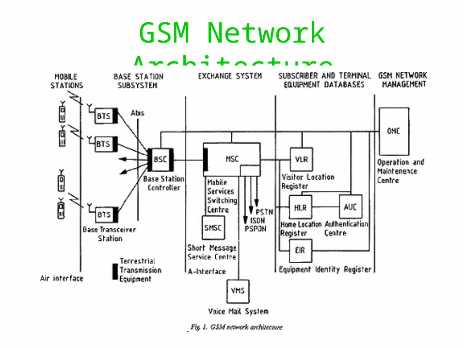
GSM Network Architecture
Mobile Station• The MS consists of the mobile equipment (terminal)
and a smart card called the subscriber identity module (SIM)
• It is the SIM card which contains all the network relevant subscriber identity information
• SIM provides subscriber with personal mobility rather than the terminal (as in first generation systems)
• Access to SIM protected by security codes (PIN and PUK codes)
Mobile Station• Typical information stored on the SIM includes
– International Mobile Subscriber Identity Number (IMSI) which is the unique identification of the subscriber (not the same as their mobile phone number)
– Information used in authenticating the SIM when it attempts to access the number
– Information indicating which bearer, supplementary and tele-services the subscriber has access to
• The mobile equipment is also uniquely identified by what is called the International Mobile Equipment Identity (IMEI) but this is not of particular importance to the “standard” operation of the network
Base Station Sub-system• The BSS consists of two parts:
– Base Station Controller (BSC)– Several Base Transceiver Station (BTS)
• The BTS primarily consists of a number the radio transmitter\receivers required to cover an individual cell plus an functionality required to support traffic transmission over the radio link (e.g. channel coding, speech coding, encryption, RF modulation)
• The BSC is a more sophisticated device which manages the radio links between the BSSs, under its control, and any MS in the cells covered by the BSSs– Allocation of channels to MS for calls– Measuring and controlling transmitter power levels
• BTSs typically linked to BSC via microwave and fixed links
Network Subsystem
• The network sub-system primarily consists of a network of telephone exchanges termed Mobile Switching Centres (MSC)– MSC interconnect using standard inter-exchange TDM links
• In addition, however, it also includes equipment to support the particular requirements of GSM mobile “telephony network”
• A special MSC termed a Gateway MSC (GMSC) is used to interconnect the GSM network with other circuit and packet switched networks
Home Location Register• The HLR is essentially a large database system which is
connected to, or integrated into, one or many MSC in the network
• Every subscriber on a GSM network will have a permanent entry in one of the HLR on their “home” network– Subscriber’s are nominally allocated to a particular “home” HLR in
a network
• The subscriber’s entry (identified by their IMSI) in their “home” HLR contains important information such as their current “location” in the GSM network and the services which the subscriber can access
Visitor Location Register
• Every MSC in the network will have a VLR attached to it (typically integrated into MSC)
• The database will contain a temporary entry for each MS that is currently within cells under the “control” of that MSC
• When a new MS enters one of these cells, it passes its IMSI to the VLR which then accesses the HLR of that MS and downloads some of its HLR data to the VLR
Visitor Location Register
• Once the VLR has this information, it can seamlessly handle any call requests relating to that MS without reference to its HLR
• Once the MS moves from the area “controlled” by the MSC, or is powered off, its VLR information is removed
• Typically, a MS that is in a cell controlled by its “home” MSC will have an entry in that MSC’s VLR (even though the same data exists in the HLR attached to that MSC)
Authentication Centre
• AuC is a further database which supports certain aspect of network security
• In particular, it contains information, known as a key, which is used to authenticate the identity of a SIM when an attempt is made by the SIM to access the network
• The same information is also involved in the process by which the digital radio transmissions to\from a mobile can be encrypted
Equipment Identity Register
• The EIR is also involved in provide network “security”
• It may also be used by a network to validate the mobile equipment (IMEI) rather than the SIM when it attempts to access the network
• The EIR is a database which contains a list of stolen and\or terminals that have failed GSM type approval tests
• Not widely used in many networks
Other Network Functions
• Additional functions that can be found in GSM networks– Operations and Maintenance Centre (OMC) – Billing Centres– Voice Mail Service (VMS)– Short Messaging Service Centre (SMSC)– Cell Broadcast Centre (CBC)
• The role of some of these will be discussed later
GSM Air Interface• Previously outlined the FDMA nature of the air interface,
with potentially several frequency carriers used in each cell• Each frequency carrier also has a TDMA nature • The TDMA frame length of approximately 8x0.577 ms
consists of 8 timeslots (“burst” periods) each nominally of a 156.25 bits duration (270.8kbps)
• Therefore, each frequency carrier actually supports 8 physical channels
• Typically, burst period 0 in each frame is typically not used for traffic data but for signalling data
GSM Air Interface
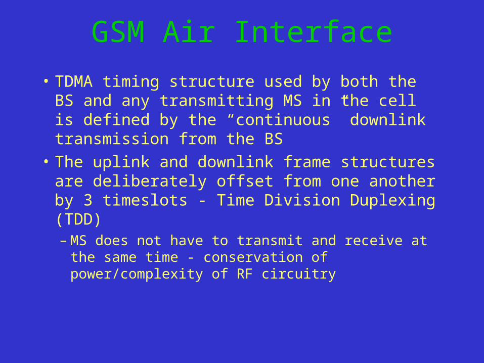
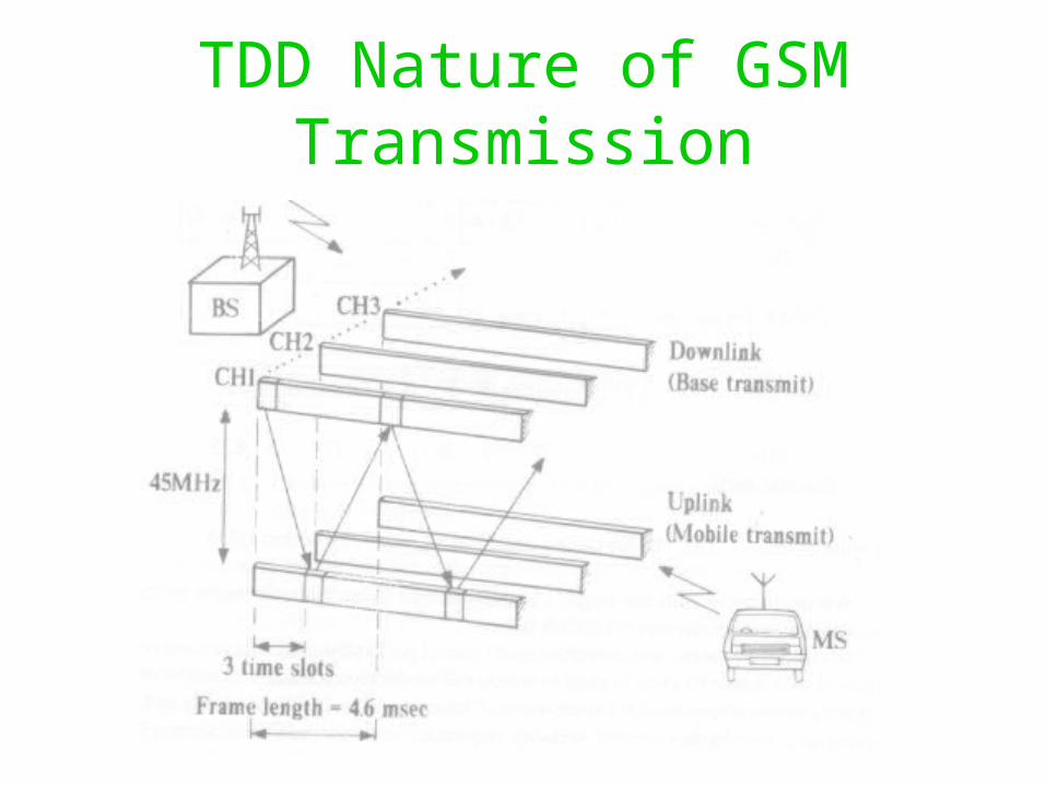
• TDMA timing structure used by both the BS and any transmitting MS in the cell is defined by the “continuous” downlink transmission from the BS
• The uplink and downlink frame structures are deliberately offset from one another by 3 timeslots - Time Division Duplexing (TDD)– MS does not have to transmit and receive at the same
time - conservation of power/complexity of RF circuitry
TDD Nature of GSM Transmission
Physical Channels• A single “Physical Channel” consists of one burst period
per TDMA frame on a specific FDMA carrier
• However, the relationship between physical channels and the data they contain is NOT simple– For example, a specific burst period on a carrier is NOT used to
carry user traffic every frame – For example, burst period N on a carrier has a different meaning
dependent on which frame it is in a 26 or 51 frame multi-frame – Even more complex time-relationships exist on burst periods
used to carry control, or signalling, information
Overview of GSM Timing Structures
• 8 Burst Periods (576.9 s) = 1 TDMA Frame (4.615 ms)• TDMA frames grouped into either:
– 26 TDMA frames (120 ms)
– 51 TDMA frames (235.4 ms)
to form a multi-frame (depending upon use of burst periods - signalling or traffic)
• 51 x 26 frame multi-frames, or 26 x 51 frame multi-frames form a super-frame (6.12 s)
• 2048 super-frames form a cryptographic hyper-frame (3 hr 28 min 53 s)
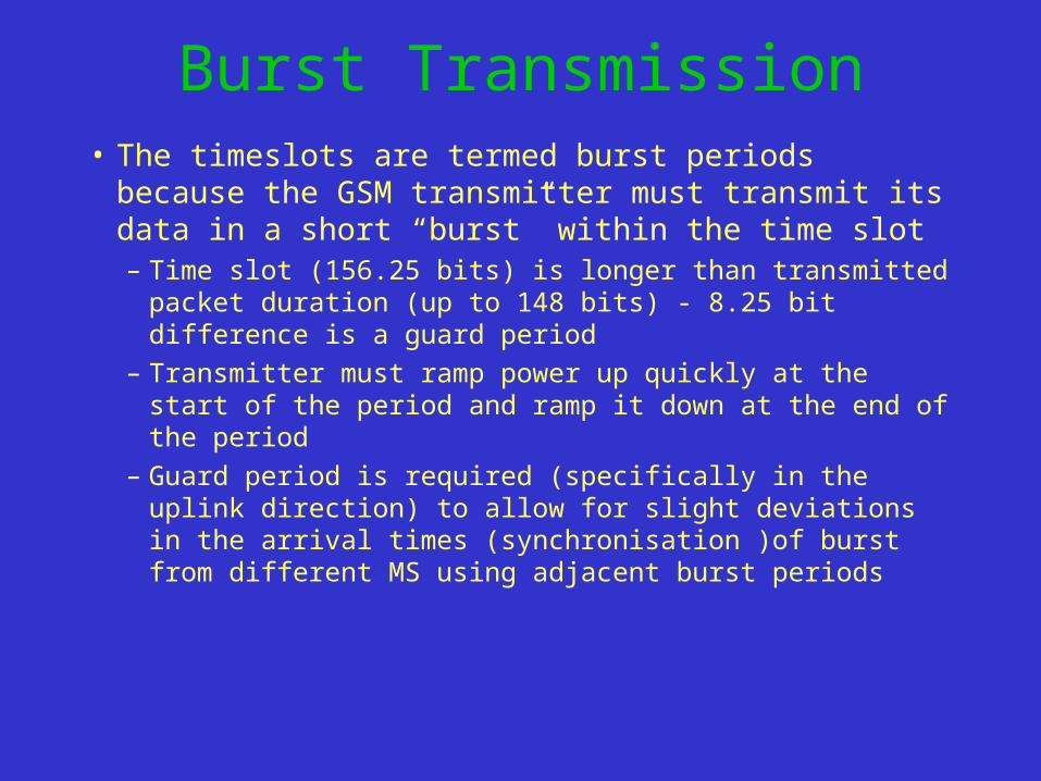
Burst Transmission• The timeslots are termed burst periods because the GSM
transmitter must transmit its data in a short “burst” within the time slot– Time slot (156.25 bits) is longer than transmitted packet
duration (up to 148 bits) - 8.25 bit difference is a guard period– Transmitter must ramp power up quickly at the start of the
period and ramp it down at the end of the period– Guard period is required (specifically in the uplink direction)
to allow for slight deviations in the arrival times (synchronisation )of burst from different MS using adjacent burst periods
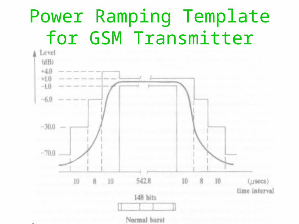
Power Ramping Template for GSM Transmitter
Types of Bursts• Four different types used in GSM depending on
function of transmission– Normal Burst (used in both MS and BS in most cases)– Frequency Correction Burst (transmitted by BS to supply
all MS with a frequency reference to aid receiver carrier synchronisation)
– Synchronisation Burst (transmitted by BS to aid MS “equalisation” circuits)
– Random Access Burst (transmitted by MS when “first” attempting to transmit to a BS in a cell)
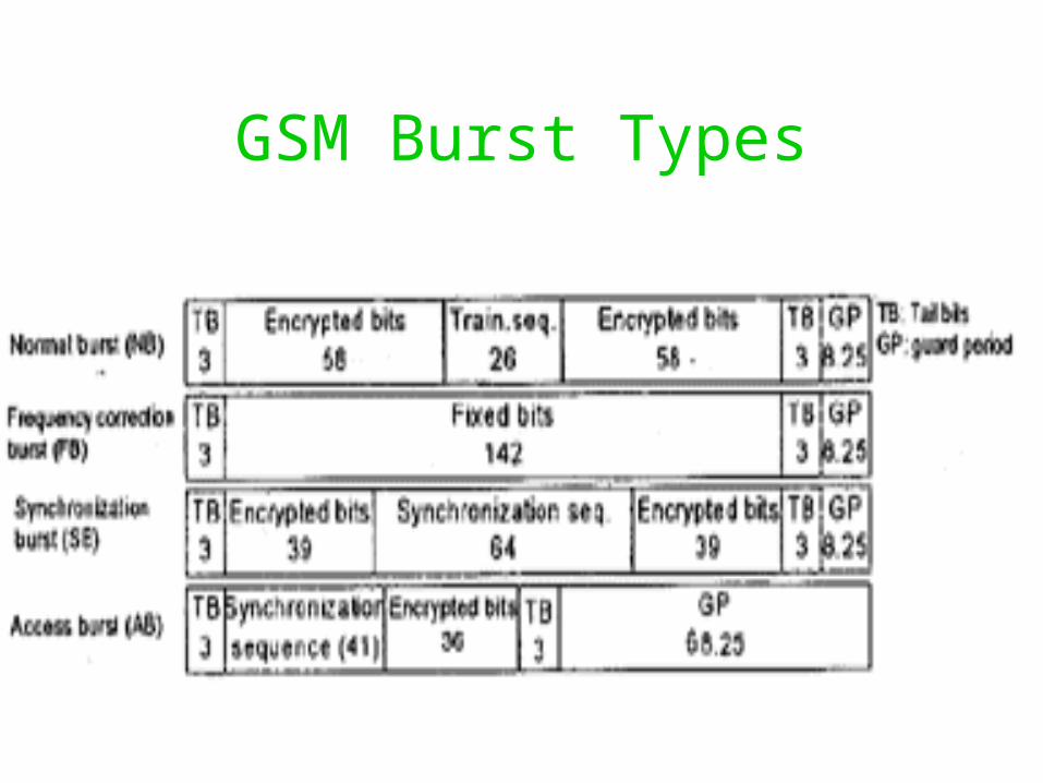
GSM Burst Types
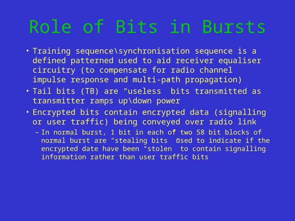
Role of Bits in Bursts• Training sequence\synchronisation sequence is a defined
patterned used to aid receiver equaliser circuitry (to compensate for radio channel impulse response and multi-path propagation)
• Tail bits (TB) are “useless” bits transmitted as transmitter ramps up\down power
• Encrypted bits contain encrypted data (signalling or user traffic) being conveyed over radio link– In normal burst, 1 bit in each of two 58 bit blocks of normal burst
are “stealing bits” used to indicate if the encrypted date have been “stolen” to contain signalling information rather than user traffic bits
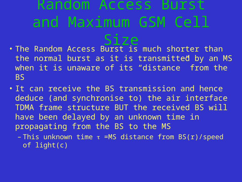
Random Access Burst and Maximum GSM Cell Size
• The Random Access Burst is much shorter than the normal burst as it is transmitted by an MS when it is unaware of its “distance” from the BS
• It can receive the BS transmission and hence deduce (and synchronise to) the air interface TDMA frame structure BUT the received BS will have been delayed by an unknown time in propagating from the BS to the MS– This unknown time =MS distance from BS(r)/speed of
light(c)
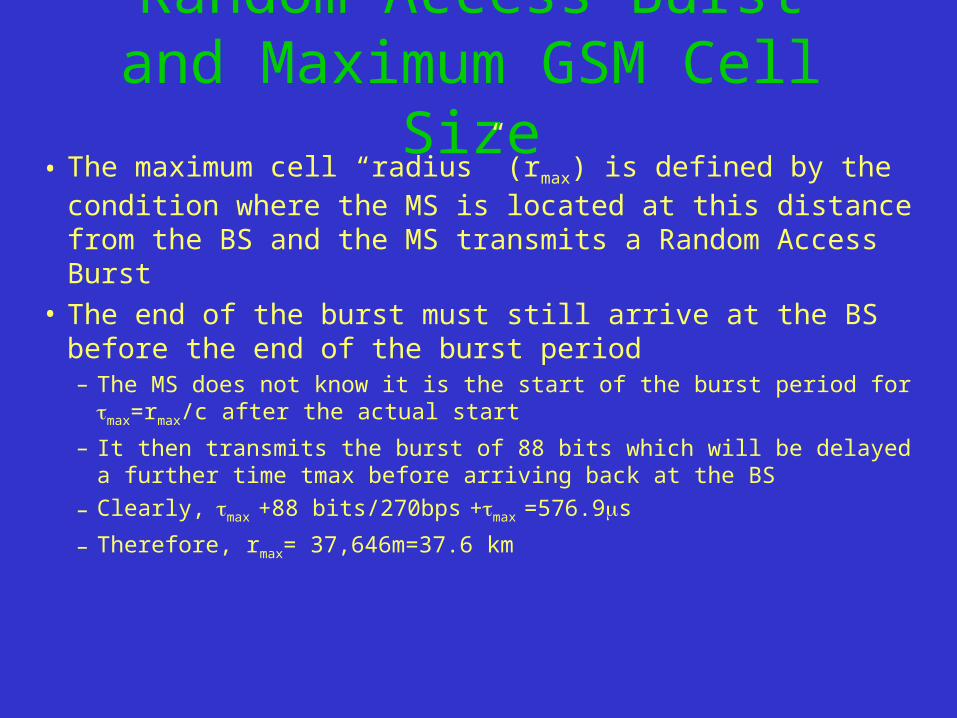
Random Access Burst and Maximum GSM Cell Size
• The maximum cell “radius” (rmax) is defined by the condition where the MS is located at this distance from the BS and the MS transmits a Random Access Burst
• The end of the burst must still arrive at the BS before the end of the burst period– The MS does not know it is the start of the burst period for max=rmax/c after
the actual start
– It then transmits the burst of 88 bits which will be delayed a further time tmax before arriving back at the BS
– Clearly,max +88 bits/270bps +max =576.9s
– Therefore, rmax= 37,646m=37.6 km
Other Air Interface Issues• A number of other GSM air interface issues should be
examined:– Timing Advance– Power Control– Discontinuous Transmission– Discontinuous Reception– Frequency Hopping
• All of these may, or may not, be implemented in particular GSM networks but are included in the GSM specification (and hence must be implemented on all GSM MS) as an aid in minimising interference and maximising MS power usage
Timing Advance• Clearly, it is vital that the burst transmission from MS in a cell
arrive within the bounds of the burst period allocated to that MS• This is made difficult as the MS may be moving and hence the
propagation delay between MS and BS can vary• BS monitors the arrival position of a MS burst in the allocated
burst period• It must then “inform” the MS to either “advance” or “retreat”
their timing to ensure than subsequent burst arrive well within the bounds of their allocated burst period
• The BS continuously performs this task while a communication “session” is in progress with an MS
Adaptive Power Control• As well as monitoring the timing situation, the BS also performs power
measurements on the signal it receives from the MS
• BS can “instruct” the MS to either increase or decrease its transmitter power level in order to ensure that the MS is transmitting at only the maximum power necessary such that the BS can receive it – Conservation of battery life
• The MS can also monitor the power it receives from the BS during its allocated burst period and instruct the BS to increase\decrease the transmitter power during that burst period - Also minimises co-channel interference
• Both of these will occur continuously while an MS is in a communication session with a BS
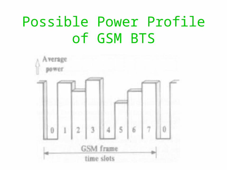
Possible Power Profile of GSM BTS
Discontinuous Transmission• In order to help maximise MS battery life and minimising co-
channel interference, GSM MS and BS only transmit normal burst containing speech “information” in their allocated burst period, during a call, if the mobile user is actually speaking
• DTX utilises a Voice Activity Detector (VAD) in the MS software which analyses the incoming speech samples to distinguish between speech and background noise
• At the other end of the radio link, “comfort noise” is injected during periods of DTX so that the listener does not hear “dead silence”
Discontinuous Reception
• The MS does not have to continuously monitor the transmissions being emitted from the BS either during calls or when idle (in case of incoming call requests)
• This means that the MS can “power down” its reception circuitry except during the periods when it must “listen” to the BS transmission
• This helps conserve MS battery life
Frequency Hopping• GSM standard does include a “slow” frequency
hopping capability for FDMA carriers in order to counteract the effect of frequency dependent distortion of carriers (e.g. multi-path fading) on quality of link– Frequency “hops” every TDMA frame
• Many networks do not implement frequency hopping in BS but ALL MS must
• BS must “inform” all MS of the frequency hopping algorithm being implemented in that cell
GSM Channel Structure• We have already introduced the physical channels used
in GSM, namely 8 burst periods per frame on an FDMA carrier
• We have also seen the need for the transmission of two distinct types of information between MS and BS, namely control (signalling) and user traffic information
• This leads to the concept of two types of channels:– Traffic Channel (TCH) used to convey user traffic information– Control Channels (CCH) used to convey signalling
information between MS and network
GSM Channel Structure• Typically, burst period 0 in a frame is used (in both directions) as
a CCH • Remaining seven burst periods in the TDMA are “nominally”
TCHs• However, this simple picture is not the complete picture• We have already seen that the normal burst in a burst period
which carries TCH can be “stolen” to carry specific types of “urgent” signalling information– Up to four consecutive frames can be stolen for this Fast Associated
Control Channel (FACCH)
GSM Channel Structure• For example, the 26 channel multi-frame structure applies to burst
periods used as TCH• In this multi-frame structure,
– In frames 0 to 11, the burst period acts as a TCH– In frame 12, it acts as a means of transmitting specific type of control
information (Slow Associated Control Channel - SACCH)– In frames 13 to 24, it again acts as a TCH– In frame 25, it is actually unused to allow the MS to do other tasks
• Similarly, the 51 frame multi-frame used on burst period carrying certain CCH (e.g. burst period 0) is used in a similarly manner to separate when different “types” of signalling information (or channels) are transmitted
Logical Channels• The GSM standard not only specifies then “when” of
different channels in that different types of information is transmitted in different burst periods, frames, multi-frames super-frames etc.
• It also distinguish the “why” of the information under the phrase of “logical channels”
• For example, it is not sufficient to identify between TCH and CCH.
• The GSM standard identifies the different types of CCH and TCH that are used
Control Channels• There are four important different classes of control channels
defined:– Broadcast Channels (BCH)
– Common Control Channels (CCCH)
– Dedicated Control Channels (DCCH)
– Associated Control Channels (ACCH)
• Each class is further subdivided to identify specific “logical channels”
• The mapping of these “logical” channels onto “physical” channels is quite complex but some examples have already been mentioned
Broadcast Channels• Broadcast channels are transmitted by the base station to
convey “information” to ALL MS in the cell
• Three different “logical” BCH exist:– Broadcast Control Channel (BCCH) conveys all information
required by the MS to access and identify the network - transmitted in burst period 0 on only one (non-hopping) carrier in a cell
– Synchronisation Channel (SCH) contains the synchronisation burst when transmitted
– Frequency Correction Channel (FCCH) contains the frequency correction burst when transmitted
Common Control Channels• CCH are shared among all MS in a cell and are used in setting
up calls from either the MS or network side• Three different types of CCH are defined:
– Paging Channel (PCH) is used by the BS to alert MS to an incoming call
– Random Access Channel (RACH) is used by MS when it attempts to request access to the network
• Access by MS in a slotted Aloha manner using Random Access Burst
– Access Grant Channel (AGCH) is used by BS to tell MS which DCH to use after it has sent a message over the RACH
Dedicated Control Channels
• The Standalone Dedicated Control Channels (SDCCH) are allocated to specific mobiles to exchange information with the network for a specific duration
• A typical use of the SDCCH would be to exchange signalling relating to a call set up
Associated Control Channels• Two types of ACH which have already been
mentioned:– Slow ACH (SACCH) which is transmitted in the TCH
burst period once every TCH multi-frame and is used for signalling of a non-urgent nature relating to the call (e.g. supplementary service and call related requests)
– Fast ACH (FACCH) which is formed by “stealing” up to four consecutive TCH bursts (frames) to convey “urgent” signalling information (e.g. handover, power control, timing advance)
Logical TCHs
• TCH are also classified accord to the type of traffic that they are carrying
• The main ones are:– TCH/F : Full rate speech codec traffic channel (1
per burst period)– TCH/H : Half rate speech codec traffic channel (2
per burst period)– TCH/n : n (e.g. 9.6, 4.8) kbps data traffic channel
(1 per burst period)
GSM Speech Codecs
• Three types of speech codec used – Full Rate Codec
– Half Rate Codec
– Enhanced Full Rate (EFR) Codec
• The Full Rate codec buffers 20 ms (160 samples) worth of 8kHz sampled speech and develops a mathematical model used to predict the 20 ms of speech
• The parameters of this model are encoded using 260 bits (every 20 ms yields 13 kbps)
GSM Speech Codecs
• Channel coding and interleaving is used to protect the bits (as with all types of TCH contents) which are then split into smaller blocks for transmission in a normal burst every frame
• Half rate codec is not widely used but was proposed in order to encode speech at 6.5 kbps and hence double capacity of each burst period
• EFR codec is a more sophisticated compression algorithm encoding speech at 13 kbps but at a higher quality (particularly for non-voice signals)
Network Support for MS Operation
• Comprehensive examination of the air interface which provides a wireless communication channel between MS and network (via the BSS)
• To support terminal mobility and roaming,the network must provide a standardised means by which MS registration, authentication, call routing and location updating are carried
• All of these require a significant amount of signalling between the MS and various parts of the network
• Already examined the means by which various types of signalling channels
Network Support for MS Operation
• A data link protocol (LAPDm – mobile) ensures reliable data link of the wireless signalling channels
• Within network, signalling messages are passed between entities using a CCS protocol called Signalling System No.7 (SS7)
• Layer 3 of the GSM stack is formed of three sub-layers– Radio Resource (RR) Management– Mobility Management (MM)– Connection Management (CM)
• MS software implements all three sub-layers but different devices in the networks implement the other end of the three network sub-layers
Radio Resource Management• RR sub-layer is concerned with the establishment, maintenance
and termination of the link (radio and possibly fixed) between an MS and the MSC to support calls
• MS, BSS and MSC are involved are the main components of the network involved
• RR sub-layer session is initiated by the MS either by:– MS initiating a RR session to set up an outgoing call– MS responding to a paging messaging to support an incoming call
• RR sub-layer has responsibility for management of radio features such as power control, timing advance, DTX, DRX and Handover
Call Handover
• Fundamentally important function to support seamless terminal mobility
• Allows MS to continue a call in progress while moving between different cells in the network– Support of the call is handed over to a different BTS to ensure
continuity of the call as the MS moves
• The procedures and operation of handover are one of the most important function of the RR sub-layer
• Handover is normally by MS or MSC (to distribute traffic or loading more evenly in a cell or cell cluster)
Call Handover• An MS with a call in progress continuously monitors the strength (quality)
of signals (in the BCH) received from up to 16 “neighbouring” cells• List of the six best “possible” candidate cells for handover is transmitted
to the BSC (and MSC) once every second• MSC may initiate call handover under limited circumstances as a means
of load or traffic balancing• The four types of Handover involve transferring support of the call
between:– Traffic channels in the same cell– BTS controlled by the same BSC– BTS controlled by different BSC but “belonging” to the same MSC– BTS controlled by different BSC
Types of Call Handover• The first two are termed “internal handovers” are controlled by
the RR software on the controlling BSC without reference to the MSC
• The last two are termed “external handovers” are handled by the RR software on the controlling MSC, possibly in communication with the new controlling MSC
• The call remains routed through the original “anchor MSC” and it DOES remain responsible for most aspects of call support– New controlling MSC’s, the “relay MSC”, primary responsibility is to
support any future inter-BSC handovers
Handover Decision Algorithms• “Minimum Acceptable Performance” algorithm only
allows handover to be considered if increasing the MS transmitter signal power (under instruction from BSS) does not result in an improvement in quality of signal received– Very simple and commonly used but can result in cell boundary
“smearing” as a MS continues to transmit at peak power even after moving into area covered (at lower power) by another BTS
• “Power Budget” algorithm allows handover to initiated if the link (signal) quality can be maintained by another BTS at the same, or lower, power– Far more complicated to implement but much reduced co-channel
interference implications
Mobility Management• Mobility Management uses the RR sub-layer (to maintain
a signalling link) and its primary functions are to support :– terminal mobility – aspects of security – Authentication
• Primary role is to support a mechanism by which the network “knows” the “location” of a powered-on MS in order to efficiently route calls to that mobile
• To this end, the network of cells is divided into “location areas” which are typically a group of cell clusters controlled by the same MSC
Location Updating• A powered on MS is informed of an incoming call by a signalling
message • This must be transmitted in the Paging channel of the cell the MS is in• In practice it is transmitted in ALL the cells of the “location area” the MS
in currently in– Smaller “location areas” result is much higher signalling traffic as MS move around– Larger “location areas” result “excessive” paging of MS on incoming calls
• MS must update certain network elements of its location :– When it first powers on (known as IMSI attach)– When it moves from one “location area” to a new one– At regular timed intervals while powered on– When it powers off (known as IMSI detach)
Location Updating Procedures• Location updating involves MSCs, HLR and VLR• When an MS switches on, or moves into a new location area, it
must inform the network of this• MS informs the MSC\VLR controlling the area of the “location
area” it is in • The VLR then informs the HLR of the MS (by an SS7 signalling
message) that it should be interrogated if any incoming calls need to be routed to the MS
• HLR verifies that the MS is allowed access and sends to the VLR all information from its records need to support calls to\from that MS
• HLR also informs the “old” VLR the MS was registered on to cancel its database entry
Location Updating Procedures
• MS must also send regular (at a network defined interval) location updating messages to the network
• Failure to do so (such as when an MS goes out of coverage) results in that MS being marked as “out of reach\de-activate” thus resulting in their VLR entry being cancelled
• Similar operation occurs when the IMSI “detaches” when the MS is powered off (rather than going out of coverage)
Authentication Procedure
• Authentication procedure carried out at beginning of each access by MS to network
• AuC and SIM implement the A3 authentication algorithm with the same random number generated by AuC
• Both entities carry out the algorithm with the subscriber’s secret key
• SIM transmits the result of the algorithm back to AuC which compares it to its own result to authenticate SIM access
• Secret key is stored on SIM and in AuC but NEVER transmitted
Security Procedures - Encryption
• Already examined possible role or EIR to provide mobile equipment security
• Encryption of all transmissions over air interface is also an option
• Using random number and key used in authentication, a ciphering key can be generated using the A8 algorithm by both ends of the air interface link
• Ciphering keyed used to encrypt the 114 bits (2x57 bits) of data in each normal burst
• Bits are de-ciphered at other end of air interface
Security Procedures - TMSI• Security for the IMSI, particularly, over the air interface is vital (to
prevent any possibility of cloning)• Another aspect of security is minimise how often the IMSI is
transmitted across the air interface• The IMSI is only transmitted across the air interface, in signalling
messages, during the very first exchange of signalling messages at the start of a network access by an MS
• Network responds to access attempt with a signalling message containing a Temporary Mobile Subscriber Identity Number (TMSI)
• The TMSI identifies the MS in all subsequent signalling messages transmitted across the air interface during that communication session
Communication Management
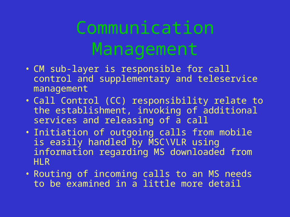
• CM sub-layer is responsible for call control and supplementary and teleservice management
• Call Control (CC) responsibility relate to the establishment, invoking of additional services and releasing of a call
• Initiation of outgoing calls from mobile is easily handled by MSC\VLR using information regarding MS downloaded from HLR
• Routing of incoming calls to an MS needs to be examined in a little more detail
MS Terminated Call
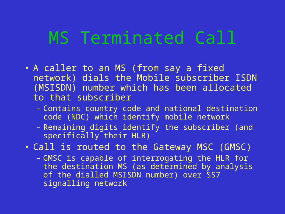
• A caller to an MS (from say a fixed network) dials the Mobile subscriber ISDN (MSISDN) number which has been allocated to that subscriber– Contains country code and national destination code
(NDC) which identify mobile network– Remaining digits identify the subscriber (and
specifically their HLR)
• Call is routed to the Gateway MSC (GMSC)– GMSC is capable of interrogating the HLR for the
destination MS (as determined by analysis of the dialled MSISDN number) over SS7 signalling network
MS Terminated Call
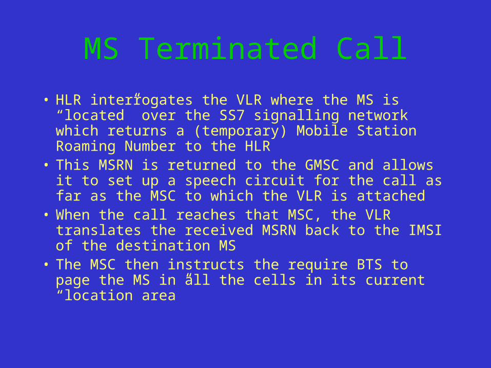
• HLR interrogates the VLR where the MS is “located” over the SS7 signalling network which returns a (temporary) Mobile Station Roaming Number to the HLR
• This MSRN is returned to the GMSC and allows it to set up a speech circuit for the call as far as the MSC to which the VLR is attached
• When the call reaches that MSC, the VLR translates the received MSRN back to the IMSI of the destination MS
• The MSC then instructs the require BTS to page the MS in all the cells in its current “location area”
GSM Supplementary Services
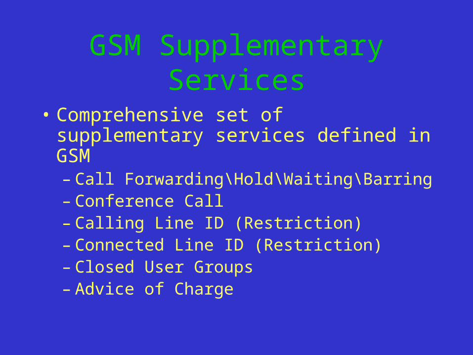
• Comprehensive set of supplementary services defined in GSM– Call Forwarding\Hold\Waiting\Barring– Conference Call– Calling Line ID (Restriction)– Connected Line ID (Restriction)– Closed User Groups– Advice of Charge
GSM Teleservices• Wide range of Teleservices
– Telephony– Group 3 Fax Service– Voice\Fax Mail– Short Messaging Service (SMS)– Cell Broadcast Service (CBS)
• Delivered over various speech and data bearer services• Data services can be transparent or utilise a comprehensive data link layer
protocol (Radio Link Protocol (RLP)• Data\Fax services utilise a digital bearer service and hence do NOT have a
modem at the MS– Network (MSC) requires a inter-working function (IWF) (i.e. a modem bank) to allow
inter-working with non-ISDN terminals (e.g. PSTN)
Short Messaging Service
• SMS allows 160 character messages to be sent to specific subscriber(s)
• Messages are transmitted to\received by MS over signalling channels
• All incoming short messages are processed by the Short Messaging Service Centre (SMSC)
• Messages stored (for a certain duration) on SMSC if desired recipient MS is powered off
• SMSC will receive messages from:– GSM subscribers– Voice or modem (DTMF) equipped Messaging Bureau– Internet
Cell Broadcast
• Uni-directional messaging service controlled by a Cell Broadcast Centre (CBC)
• Messages of up to 93 characters delivered to MS over signalling channel
• Messages can be broadcast to all the MS is specific geographic areas
New Data Services• Two new GSM data (bearer) services have been
standardised– High Speed Circuit Switched Data Service (HSCD)– General Packet Radio Service (GPRS)
• Current data bearer services only offer up to 9.6 kbps• HSCD allows a high speech data connection by
allocating multiple (up to 7) burst periods on a carrier to an MS
• GPRS provides a high speed (> 100 kbps) packet switched service to MS by dynamically utilising unused burst periods over the air interface