Embed Size (px)
Citation preview
1 | P a g e
GSM Based Energy Meter
Name: Somanath Behera
Roll: 111EC0167
Electronics & Communication Engineering Department
National Institute of Technology, Rourkela
Rourkela – 769008, India
2 | P a g e
GSM Based Energy Meter
Dissertation submitted for the partial fulfilment
Of the requirements of the degree of
“Bachelor of Technology”
In
Electronics and Communication Engineering
By
Somanath Behera
Roll No.: 111EC0167
Under the guidance
Of
Prof. Ayas Kanta Swain
Electronics & Communication Engineering Department
National Institute of Technology Rourkela
Rourkela – 769008, India
3 | P a g e
Electronics & Communication Engineering Department
National Institute of Technology, Rourkela
C E R T I F I C A T E
This is to certify here that the work done in this thesis entitled GSM Based Energy
Meter by Somanath Behera, bearing roll number 111EC0167, is an authentic record of an
original research work done out by him under my knowledge and guidance for the partial
fulfilment of the requirements of the degree of Bachelor of Technology in the department of
Electronics and Communication Engineering.
Neither the thesis nor any part of this thesis has been submitted before for any kind of
fulfilment of degree or any academic award elsewhere.
Prof. Ayas Kanta Swain
Supervisor
Department of Electronics and Communication
National Institute of Technology Rourkela – 769008 (Odisha, India)

4 | P a g e
Acknowledgment
This dissertation although work of an individual but it has been benefited in various
ways from several people. While it could be simple to name everyone or them all, it would
never be easy to thank them enough for their support.
The enthusiastic guidance and active support of Prof. Ayas Kanta Swain has inspired
me to stretch beyond my limits and to work hard. His motivating and inspiring insight has
guided my thinking throughout my work and to improve the results in my work. My sincere
thanks to him.
Finally, it is my honour and duty to thank my family members and friends for lots of
their love and support. Finally it is my duty to sincerely thank my parents for their
unconditional love.
Somanath Behera

5 | P a g e
Abstract
The TM4C123GH6PM board is the most recent system-on-chip (SOC), which falls
under ARM family of boards and devices. This family of boards and devices comes under
the powerful 32-bit ARM family afteradding a lots of new features, properties and flexibility to
support robust single, 2 and three phase metrology solutions. This project is only for domestic
uses as we have considered only the single phase case. We can also extend this project for two
phase and three phase environment. In that case this will be very helpful for industrial
application. Here we take input as current and voltage from the main supply and we use
sensing circuits to make its level compatible with that of ARM Processor. Here the GSM
module is added to reduce the manual work and complexity of analog meters. Here we can
send sms to every individual about their energy usage. The calculation and data sending
capacity of this model is made easier by the source code. Handling these complex systems
easily with the help of software has made it more popular. Higher level of current capacity
can easily be obtained by simple replacement of the shunt resistor or its value. We can
achieve any desired value by either by changing the ratio in transformer or the resister value
of voltage divider circuit. The TM4C123GH6PM has a powerful 60 MHz CPU with ARM
architecture. The analog front end consists of up to two channel of 12-bit analog-to-digital
converters (ADC), with conversion time 2.44 micro second per channel. The software
supports calculation of various parameters for single phase energy calculation. The key
parameters measured during energy measurements are: RMS current and voltage, energies.
Finally the calculated value of power and other parameters are displayed on 16x2 LCD and
the same data is sent to user and station via SMS using GSM module.

6 | P a g e
CONTENTSCertificate 3
Acknowledgment 4
Abstract 5
Content 6
List of figures 8
1. Introduction……………………………………………………………….……….…9
1.1 Objective……………………………………………....……………………………..9
1.2 Scope of project……………………………………………………….…………….10
1.3 Purpose and Description of Project…………………………………………………10
2. Hardware Requirements…………………………….………………………………11
2.1 Hall effect sensor…………………………………………………………………...11
2.2 LA 55-P Op Amp………………………………………….………………………..11
2.3 TM4C123GH6PM Board…………………………………………………………...12
2.4 LCD…………………………………………………………………………………13
3. Measurement quantities related to energy………………….………………………..14
3.1 General Theory power………………………………………………………………14
3.1.1 Real power……………………………………...………………...……………..14
3.1.2 Reactive power…………………………………………………………………..14
3.1.3 Apparent power………………………………………………………………….15
4. Voltage and Current sensing………………………………….……………………..18
4.1 Current sensing…………………………………………………...………...……….18
4.2 Voltage sensing…………………………………………………...………………...19
5. Hardware implementation of sensing circuits………..……………………………..21
5.1 Voltage sensing……………………………….………………………….…………21
5.2 Current sensing……………………………………………………………………..22
6. ARM Processor (TM4C123GH6PM)…………………..…………………………..23
7 | P a g e
7. GSM module………...………………………………………………………………25
8. Block Diagram………………...…………………………………………………….26
9. Data Analysis and Display………………………..………………………………...27
10. Conclusion……………………………………………..……………………………28
11. Bibliography…………………………………………..…………………………….30

8 | P a g e
LIST OF FIGURES:
1) Fig 2.1 LA-55……………………………………………………………………………11
2) Fig 2.2 TL081CP Pin configuration……………………………………………………..12
3) Fig 2.3 TM4C123GH6PM Architecture………………………………………………...13
4) Fig 2.4 16x2 LCD……………………………………………………………………….13
5) Fig 3.1 Energy curve for resistive case……….…………………………………………16
6) Fig 3.1 Energy curve for inductive case…………………………………………………17
7) Fig 3.1 Energy curve for capacitive case……………..…………………………………17
8) Fig 3.4 Single Phase active and reactive power…………………………………………18
9) Fig 4.1 LA-55P (Hall Effect sensor)……………………………………………………..19
10) Fig 4.2 Current Sensing Design……….………………………………………………..20
11) Fig 4.3 Transformer……………………………………………………………………..21
12) Fig 4.4 Voltage Sensing Design………………………………………………………...22
13) Fig 5.1 Hardware implementation of Voltage sensing Design……………….………...22
14) Fig 5.2 Hardware implementation of Current sensing Design…………………………23
15) Fig 6.1 The four basic components of Microcontroller………………………………...24
16) Fig 6.2 TM4C123GH6PM Architecture……………………………….……………….25
17) Fig 7.1 GSM Module…………………………………………………………………...26
18) Fig 8.1 Block diagram of GSM based Energy meter…………………………………..26
9 | P a g e
1. Introduction:
These days have evolved more into digital world. This design helps us to measure active
power/energy, potential, and current flowing in a single-phase environment. The heart of the
meter is an ARM cortex M4 processor. All the readings and measurements are taken in the
digital domain, so we use ADC, and measurement results are displayed in LCD. Then the data
calculated is sent as SMS via GSM module. This project is only for domestic uses as we have
considered only the single phase case. We can also extend this project for two phase and three
phase environment. In that case this will be very helpful for industrial application. Here we
take input as current and voltage from the main supply and we use sensing circuits to make
its level compatible with that of ARM Processor. Here the GSM module is added to reduce
the manual work and complexity of analog meters. Here we can send sms to every individual
about their energy usage. The calculation and data sending capacity of this model is made
easier by the source code. Handling these complex systems easily with the help of software
has made it more popular. These are also known as power meter and vice versa. According to
terminology, active power is a measure of what is required or consumed in order to do a task
or perform any particular useful work. These energy meters described in this application also
can be referred to as an energy meter or a power meter or a watt-hour meter. The Digital
calibration is very fast and efficient, minimizing the overall calculation time and cost. The
brain of this meter is the software firmware/source code, which does all the calculation and
interfacing.
1.1 Objective
The main objective and aim of this intended project is to implement and construct a
digital power or energy meter for domestic appliances. This energy meter will measure the
electrical energy digitally, and send messages to individual user so that user can easily identify
how much energy they used at one time. We can use only 160 characters to send messages.

10 | P a g e
1.2 Scope of Project
Since the energy meter can calculate or determine the energy consumed by the
household appliances, the data can be used for the following studies:
•Calculate the average electrical energy or we can say power consumption of selected
appliances used in residential sector.
• Examine of the impact of energy efficiency labelling of domestic appliance.
• Forecast of future energy desire in residential sector based on end-use modelling techniques.
• Implementation of special website/programmers that can teach and promote efficient and
wise use of energy.
•Prevent tampering and other malpractices
1.3 Purpose and Description of Project:
The TM4C123GH6PM board is the most recent system-on-chip (SOC), which comes
under ARM family of boards and devices. This family of boards and devices comes under
the powerful 32-bit ARM family after adding a lots of new features, properties, advantage and
flexibility to support robust single, 2 and three phase metrology solutions. This project is only
for domestic uses as we have considered only the single phase case. We can also extend this
project for two phase and three phase environment. In that case this will be very helpful for
industrial application. Here we take input as current and voltage from the main supply and we
use sensing circuits to make its level compatible with that of ARM Processor. Here the GSM
module is added to reduce the manual work and complexity of analog meters. Here we can
send sms to every individual about their energy usage. The calculation and data sending
capacity of this model is made easier by the source code. Handling these complex systems
easily with the help of software has made it more popular.
The device has a powerful 60 MHz CPU with ARM architecture. The analog front end
consists of up to two channel of 12-bit analog-to-digital converters (ADC), with conversion
time 2.44 micro second per channel. A 32-bit x 32-bit hardware on this chip can be used to
further accelerate math intensive operations during energy calculation. We have a power
supply of 220V and 5A so all we do is use two sensing circuit for both voltage and current

11 | P a g e
sensing. We have to drop the values of these two parameters under our required level that is
below 3.3V. The software supports calculation of various parameters for single phase energy
calculation. The key parameters measured during energy measurements are: RMS current and
voltage, energies. These results are shown on a 16x2 LCD and the data calculated are sent as
SMS via a GSM module.
2 Hardware Requirements:
2.1 Hall effect sensor(LA55P):
This is a current sensor which converts current into voltage by sensing the current
flowing through it. Here in this project we have used the sensor LA-55P. The working
principle of this sensor is as follows. The wire is winded around the sensor and when the
current flow it senses the current and converts it to voltage. The conversion ratio depends on
the number of turns. The Hall Effect sensor is basically a transducer which gives voltage as
its output in response to a varying magnetic field around it.
Fig 2.1 LA-55P
2.2 TL081CP Op Amp:
This one type of general purpose amplifier used for various application. It can be used
for different purposes like amplification, attenuation, level shifting, rectifying etc. By varying
the design and value of resister we can perform different configuration and we can do different

12 | P a g e
works. Their performance is best over a temperature range of 0C to +700C. These amplifier
are the most important and useful part the circuits which are used as an attenuator, level shifter
and precision rectifier, and the output of this is applied to the processor to enables the
calculation of the different parameter related to current, voltage and energy meter. The degree
of amplification or attenuation or level shifting depends on the value of resisters we use.
Connection diagram of TL081 is as shown below:
Fig 2.2 TL081CP Pin configuration
2.3 TM4C123GH6PM Board:
Here we are using the board TM4C123GH6PM and the main features of this board
are:
• 43 I/O pins.
• 32k RAM.
• 256K EEPROM.
• 80MHz Cortex-M4.
• SSIs, ADC, CAN, UARTs.
• Timer, PWM, USB.
• JTAG.
• Floating point.
13 | P a g e
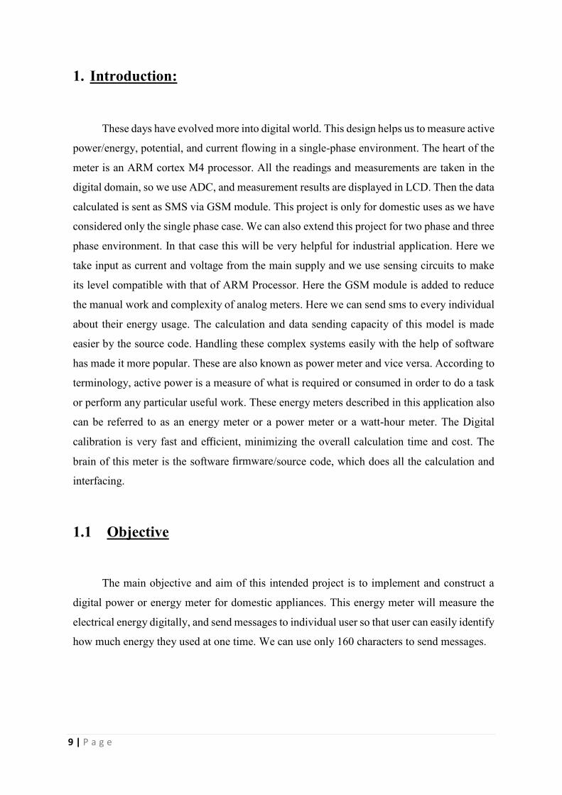
Fig 2.3 TM4C123GH6PM Architecture
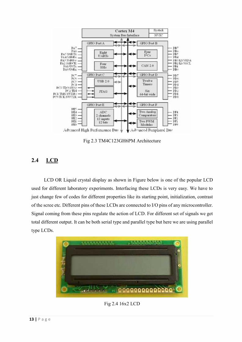
2.4 LCD
LCD OR Liquid crystal display as shown in Figure below is one of the popular LCD
used for different laboratory experiments. Interfacing these LCDs is very easy. We have to
just change few of codes for different properties like its starting point, initialization, contrast
of the scree etc. Different pins of these LCDs are connected to I/O pins of any microcontroller.
Signal coming from these pins regulate the action of LCD. For different set of signals we get
total different output. It can be both serial type and parallel type but here we are using parallel
type LCDs.
Fig 2.4 16x2 LCD

14 | P a g e
3 Measurement of quantities related to energy:
3.1 General Theory Power:
3.1.1 Real power:
For any voltage and current that is varying with respect to time has a time varying power
that is transferred to the load. This power transferred is called the instantaneous power. It is
the product of root mean square value of both current and voltage and the phase difference
between them. To get the real power we have to take the average value of this instantaneous
power. The formula for this real power is given as:
3.1.2 Reactive Power:
In an Alternative Current circuit current and voltage go rise and the fall at the same
period, then only the Active power is transmitted through the circuit and when there we have
a time shift between these then both active and reactive power is generated or we can say
transmitted. If we take the average of this energy with respect to time we can see that the
average flow of energy flowing from one end to another is caused by the real power whereas
the reactive power is negligible. This is the imaginary part. It flows in the opposite direction
that of the active energy or real power in different components like capacitor or inductors.
Producing a result or conclusion that reactive powers are neither produced nor consumed.
15 | P a g e
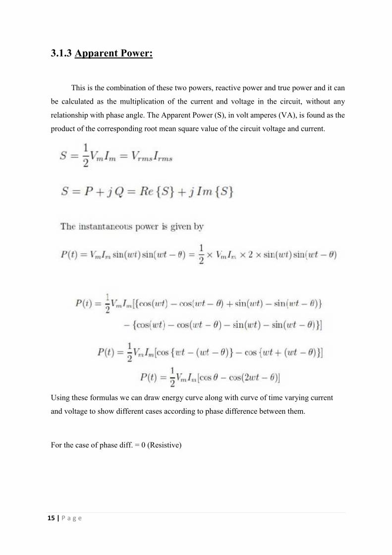
3.1.3 Apparent Power:
This is the combination of these two powers, reactive power and true power and it can
be calculated as the multiplication of the current and voltage in the circuit, without any
relationship with phase angle. The Apparent Power (S), in volt amperes (VA), is found as the
product of the corresponding root mean square value of the circuit voltage and current.
Using these formulas we can draw energy curve along with curve of time varying current
and voltage to show different cases according to phase difference between them.
For the case of phase diff. = 0 (Resistive)

16 | P a g e
Fig 3.1 Energy curve for resistive case
For the case of phase diff. = 90 (Inductive)
Fig 3.2 Energy curve for inductive case
For the case of phase diff. = -90 (capacitive)

17 | P a g e
Fig 3.3 Energy curve for capacitive case
For single phase active and reactive power:
Fig 3.4 Single Phase active and reactive power

18 | P a g e
4 Voltage and Current sensing:
4.1 Current Sensing:
4.1.1 Hall Effect Sensor:
This is a current sensor which converts current into voltage by sensing the current
flowing through it. Here in this project we have used the sensor LA-55P. The working
principle of this sensor is as follows. The wire is winded around the sensor and when the
current flow it senses the current and converts it to voltage. The conversion ratio depends on
the number of turns. The Hall Effect sensor is basically a transducer which gives voltage as
its output in response to a varying magnetic field.
Fig 4.1 LA-55P (Hall Effect sensor).
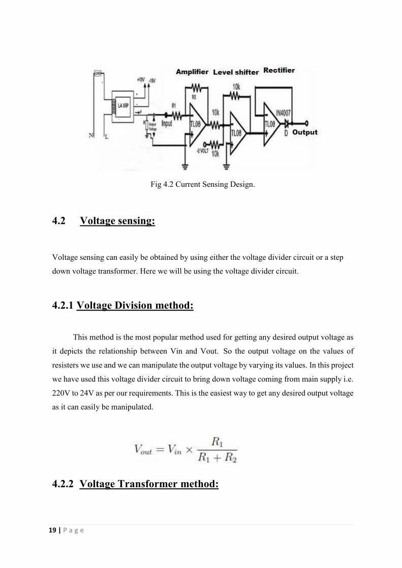
4.1.2 Current input:
The sensing voltage is low in amplitude and difficult to measure then it is passes through
amplifier. The amplification factor is depend upon values of R1 and R2, and step up the
voltage below 1 volt peak to peak. Output consist both positive and negative cycle but
processor ADC respond or measure only positive values, it require level shifter to add a DC
offset and pass to precision rectifier, It prevents any excursion of negative voltage. We use a
common ground.
19 | P a g e
Fig 4.2 Current Sensing Design.
4.2 Voltage sensing:
Voltage sensing can easily be obtained by using either the voltage divider circuit or a step
down voltage transformer. Here we will be using the voltage divider circuit.
4.2.1 Voltage Division method:
This method is the most popular method used for getting any desired output voltage as
it depicts the relationship between Vin and Vout. So the output voltage on the values of
resisters we use and we can manipulate the output voltage by varying its values. In this project
we have used this voltage divider circuit to bring down voltage coming from main supply i.e.
220V to 24V as per our requirements. This is the easiest way to get any desired output voltage
as it can easily be manipulated.
4.2.2 Voltage Transformer method:

20 | P a g e
In this case we decide the value of output voltage on the basis of the ratio of secondary and
primary voltage can be obtained from equation as:
So we can get any desired output voltage by varying either the number of turns in primary and
secondary coils or the corresponding current flowing through it.
Fig 4.3 Transformer.
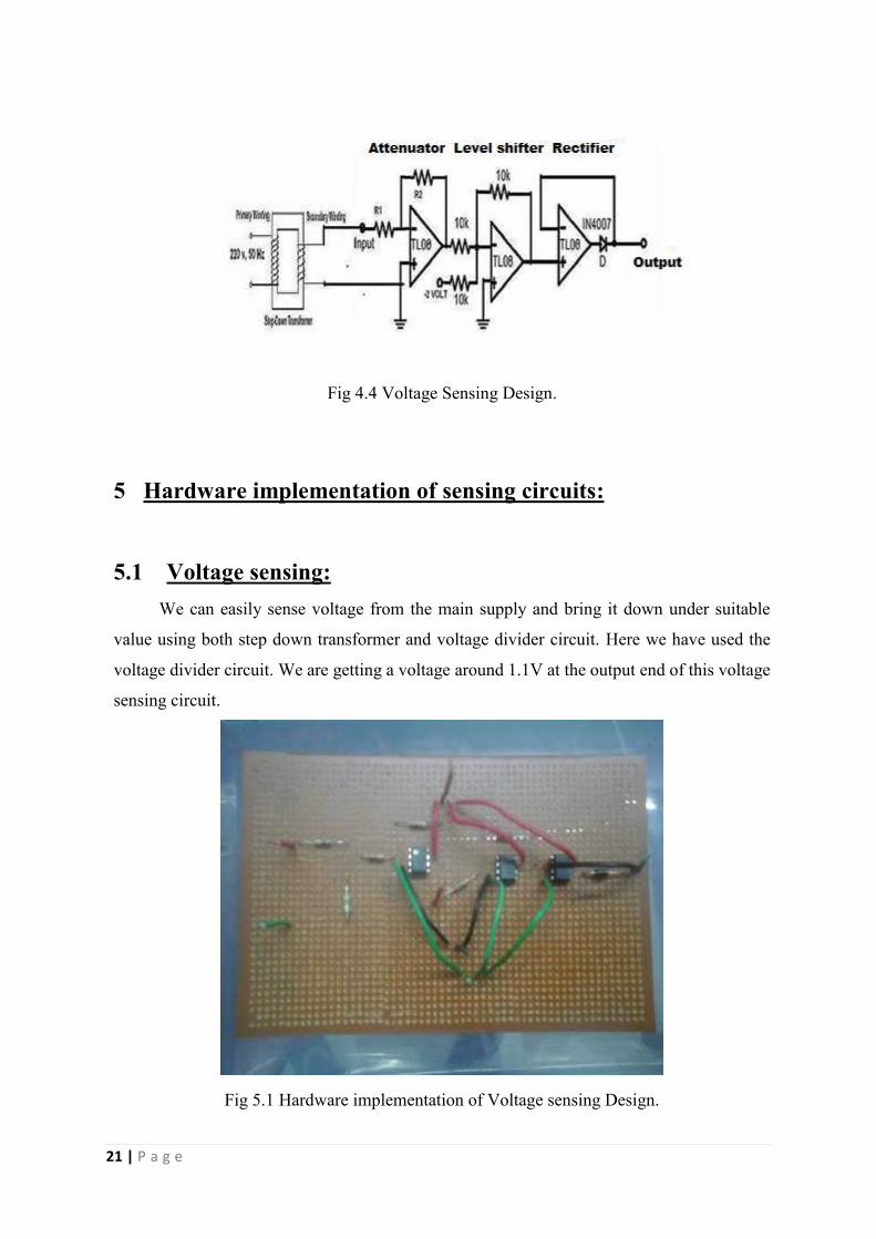
4.2.3 Voltage Inputs:
In the figure below, 220 volt is step down to 24 volt peak to peak through step down
transformer. The output of transformer is not measurable; to make it measurable it passes
through attenuator to step down the voltage below 1 volt peak to peak. Output consist both
positive and negative cycle but processor ADC respond or measure only positive values, it
require level shifter to add a DC offset and pass to precision rectifier, It prevents any excursion
of negative voltage. We use a common ground.
21 | P a g e
Fig 4.4 Voltage Sensing Design.
5 Hardware implementation of sensing circuits:
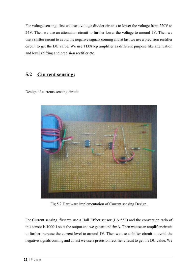
5.1 Voltage sensing:We can easily sense voltage from the main supply and bring it down under suitable
value using both step down transformer and voltage divider circuit. Here we have used the
voltage divider circuit. We are getting a voltage around 1.1V at the output end of this voltage
sensing circuit.
Fig 5.1 Hardware implementation of Voltage sensing Design.
22 | P a g e
For voltage sensing, first we use a voltage divider circuits to lower the voltage from 220V to
24V. Then we use an attenuator circuit to further lower the voltage to around 1V. Then we
use a shifter circuit to avoid the negative signals coming and at last we use a precision rectifier
circuit to get the DC value. We use TL081cp amplifier as different purpose like attenuation
and level shifting and precision rectifier etc.
5.2 Current sensing:
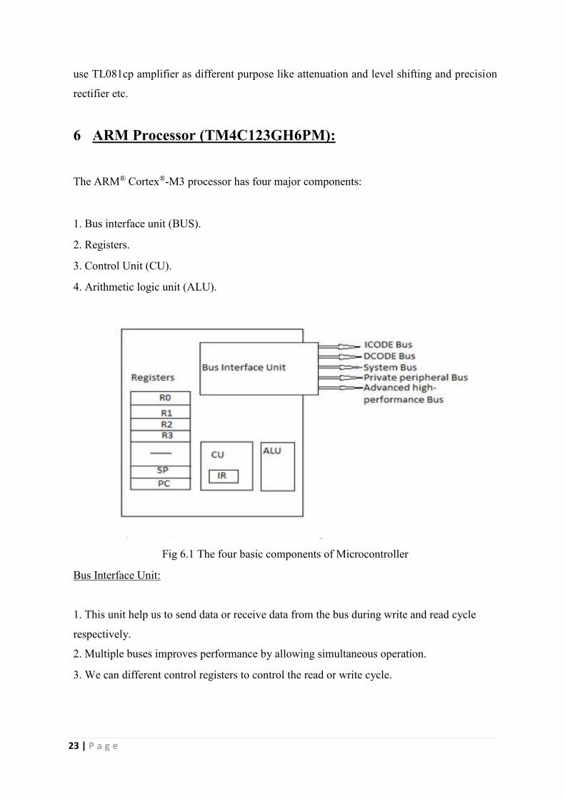
Design of currents sensing circuit:
Fig 5.2 Hardware implementation of Current sensing Design.
For Current sensing, first we use a Hall Effect sensor (LA 55P) and the conversion ratio of
this sensor is 1000:1 so at the output end we get around 5mA. Then we use an amplifier circuit
to further increase the current level to around 1V. Then we use a shifter circuit to avoid the
negative signals coming and at last we use a precision rectifier circuit to get the DC value. We
23 | P a g e
use TL081cp amplifier as different purpose like attenuation and level shifting and precision
rectifier etc.
6 ARM Processor (TM4C123GH6PM):
The ARM® Cortex®-M3 processor has four major components:
1. Bus interface unit (BUS).
2. Registers.
3. Control Unit (CU).
4. Arithmetic logic unit (ALU).
Fig 6.1 The four basic components of Microcontroller
Bus Interface Unit:
1. This unit help us to send data or receive data from the bus during write and read cycle
respectively.
2. Multiple buses improves performance by allowing simultaneous operation.
3. We can different control registers to control the read or write cycle.

24 | P a g e
Registers:
1. High speed storage devices located in processor.
2. Can contain data or address.
Control unit:
1. It manages the sequence of operation in progress.
2. It commands to the other three components.
Control unit:
1. It manages the sequence of operation in progress.
2. It commands to the other three components.
Here we will be using the board TM4C123GH6PM and the main features of this board are:
• 43 I/O pins.
• 32k RAM.
• 256K EEPROM.
• 80MHz Cortex-M4.
• SSIs, ADC, CAN, UARTs.
• Timer, PWM, USB.
• JTAG.
• Floating point.

25 | P a g e
Fig 6.2 TM4C123GH6PM Architecture
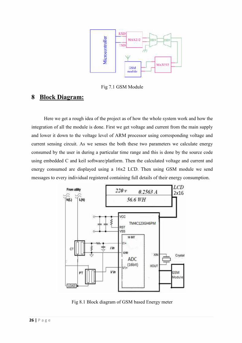
7 GSM module:
• GSM module is used to send SMS because it can easily connected to microcontroller using
serial connection and response on AT commands.
• This module communicate with mobile phones by UART interfacing.
• MAX232 is an important device than converts signal coming from RS232 into the TTL
signals and send it to the DB9 for transmitting the signal and at the other end it convers
the received signal from TTL to RS232 compatible signal.
• To communicate over UART we require three signals from three pins named, TXD (for
transmit), RXD (for receive), GND (ground).
• SMS can contain up to 140 characters in general.
• During interfacing the transmit signal coming from the serial port of a particular
microcontroller is connected with that of the transmit signal (TXD) of the serial interface
system of this GSM Modem and at the other end the receive signal that is coming from
the microcontroller serial port is also connected with the receive signal (RXD) of serial
interface system of GSM Modem.
26 | P a g e
Fig 7.1 GSM Module
8 Block Diagram:
Here we get a rough idea of the project as of how the whole system work and how the
integration of all the module is done. First we get voltage and current from the main supply
and lower it down to the voltage level of ARM processor using corresponding voltage and
current sensing circuit. As we senses the both these two parameters we calculate energy
consumed by the user in during a particular time range and this is done by the source code
using embedded C and keil software/platform. Then the calculated voltage and current and
energy consumed are displayed using a 16x2 LCD. Then using GSM module we send
messages to every individual registered containing full details of their energy consumption.
Fig 8.1 Block diagram of GSM based Energy meter

27 | P a g e
9 Data Analysis and Display:
After voltage and current measurement procedure, next step is data analysis and display.
Samples are taken from ADC peripherals and passed through following steps:
• Offset Removal
Both voltage and current sample has an offset DC value, to measure the accurate value of rms
voltage and rms current offset removal is necessary.
• Gathering samples
After eliminating offset, accumulate 1000 sample in one second and calculate rms voltage,
rms current, and consumed power on the basis of 1000 samples.
• Display
16x2 LCD display for showing the calculated data or rms voltage, current and energy
•Data sending
Data is sent as SMS via GSM module.

28 | P a g e
10 Conclusion:
This design helps us to measure active power/energy, potential, and current flowing in
a single-phase environment. The heart of the meter is an ARM cortex M4 processor. All the
readings and measurements are taken in the digital domain, so we use ADC, and measurement
results are displayed in LCD. Then the data calculated is sent as SMS via GSM module.
Energy meters are also sometimes mention to as power meters and vice versa.
Current and voltage sensor circuits are connected to their analog inputs and converted
into digital data/form. Then sampling is done and the sampled signals of the voltage and
current are manipulated by the heart of the design, microcontroller, to measure energy meter
parameter. This microcontroller also evaluates the room means square value of the voltage
and current signals we have and the energy is calculated and can easily be manipulated and
controlled by changing the source code. Finally it is displayed for the user.
This project is only for domestic uses as we have considered only the single phase case.
We can also extend this project for two phase and three phase environment. In that case this
will be very helpful for industrial application. Here we take input as current and voltage from
the main supply and we use sensing circuits to make its level compatible with that of ARM
Processor. Here the GSM module is added to reduce the manual work and complexity of
analog meters. Here we can send sms to every individual about their energy usage. The
calculation and data sending capacity of this model is made easier by the source code.
Handling these complex systems easily with the help of software has made it more popular.
The software supports calculation of various parameters for single phase energy
calculation.The key parametersmeasured during energy measurements are: RMS current and
voltage, energies. Finally the calculated value of power and other parameters are displayed on
16x2 LCD and the same data is sent to user and station via SMS using GSM module.
These types of digital energy meters with GSM module and data sending capability
reduces the tampering and other malpractices used in domestic uses and also eliminates the

29 | P a g e
manual work of taking the readings of energy used as it send a well-defined message to the
user having the contents of their data uses on a regular basis.
We can add more features like printing a receipt of the energy used and the most
important thing in these types of energy meter is that it handles these problem or any kind of
up gradation or addition of any new features in the software level. It reduces the complexity
of analog systems as a result it reduces the cost and labour.

30 | P a g e
11 Bibliography:
[1] Paramanand Nayak, Implementation of single phase watt hour meter using LPC2148 thesis
paper, NIT Rourkela, May 30, 2013.
[2] Sarwar Shahidi, Md. Abdul Gaffar, Khosru M. Salim, Design & implementation of Digital
Energy Meter with data sending capability using GSM Network, IEEE Conference on
Advances 19-21 Dec-2013, Dhaka, Bangladesh.
[3] PAV. Loss, MM. Lamego, G. C. D. Sousa, and J. L. F. Vieira. Single phase microcontroller
based energy meter. In Conference Record - IEEE Instrumentation and Measurement
Technology Conference, volume 2, pages 797–800, 1998. Cited By (since 1996):9.
[4] Single-phase power/energy meter with tamper detection. Atmel, page 40, july 2004.
[5] Tl081CP jfet-input operational amplifires. TEXAS INSTRUMENTATION
INCORPORATED, page 45, SEPTEMBER 2004.
[6] Shi-Wei Lee, Cheng-Shong Wu, Meng-Shi Chiou, and Kou-Tan Wu. Design of an
automatic meter reading system. In IECON Proceedings (Industrial Electronics Conference),
volume 1, pages 631–636, 1996. Cited By (since 1996):3.
[7] Implementation of a single-phase electronic watt-hour meter using the msp430f6736.
TEXAS INSTRUMENTATION INCORPORATED, page 27, May 2012.
[8] L. Saranovac, P. Pejovic, and M. Popovic. Digital method for power frequency
measurement using synchronous sampling. IEE Proceedings: Electric Power Applications,
148(2):225–226, 2001. Cited By (since 1996):2.
[9] R. G. Jones. A review of precision ac voltage and current measurements. IEE Colloquium
(Digest), (161):1/1–1/4, 1997.


![Smart energy meter [ based on GSM module and database ]](https://img.pdfslide.us/doc/110x75/61686bbed394e9041f6f78d2/smart-energy-meter-based-on-gsm-module-and-database-.jpg)