Embed Size (px)
Citation preview
Every effort has been made to eliminate errors and ambiguities in the information contained in this guide. Any questions concerning information presented here should be directed to SAMSUNG TELECOMMUNICATIONS AMERICA, 1301 E. Lookout Dr. Richardson, TX. 75082 telephone (972) 761-7300. SAMSUNG TELECOMMUNICATIONS AMERICA disclaims all liabilities for damages arising from the erroneous interpretation or use of information presented in this guide.
GSIMT/GSIM User Manual
7400
Samsung Telecommunications Publication Information SAMSUNG TELECOMMUNICATIONS AMERICA reserves the right without prior notice to revise information in this publication for any reason. SAMSUNG TELECOMMUNICATIONS AMERICA also reserves the right without prior notice to make changes in design or components of equipment as engineering and manufacturing may warrant. Copyright 2007 Samsung Telecommunications America All rights reserved. No part of this manual may be reproduced in any form or by any means—graphic, electronic or mechanical, including recording, taping, photocopying or information retrieval systems—without express written permission of the publisher of this material. Trademarks
is a trademark of SAMSUNG Telecommunications America, L.P. WINDOWS 95/98/XP/2000 are trademarks of Microsoft Corporation. PRINTED IN USA
I
INTRODUCTION
Purpose This document introduces the OfficeServ 7400 GSIMT/GSIM, an application module of the OfficeServ 7400, and describes procedures on installing and using the software.
Document Content and Organization This document consists of three chapters and abbreviation, which are summarized as follows:
CHAPTER 1. Overview of OfficeServ 7400 GSIMT/GSIM This chapter briefly introduces the OfficeServ 7400 GSIMT/GSIM.
CHAPTER 2. Instaling of OfficeServ 7400 GSIMT/GSIM This chapter describes the installation procedure and login procedure.
CHAPTER 3. Using OfficeServ 7400 GSIMT/GSIM This chapter describes how to use the menus of the OfficeServ 7400 GSIMT/GSIM.
ABBREVIATIONS Abbreviations frequently used in this document are described.
II
Conventions The following types of paragraphs contain special information that must be carefully read and thoroughly understood. Such information may or may not be enclosed in a rectangular box, separating it from the main text, but is always preceded by an icon and/or a bold title.
WARNING
Provides information or instructions that the reader should follow in order to avoid personal injury or fatality.
CAUTION
Provides information or instructions that the reader should follow in order to avoid a service failure or damage to the system.
CHECKPOINT
Provides the operator with checkpoints for stable system operation.
NOTE
Indicates additional information as a reference.
Examples
Indication that there is a programming example which should be remembered.
Console Screen Output The lined box with ‘Courier New’ font will be used to distinguish between the main
content and console output screen text. ‘Bold Courier New’ font will indicate the value entered by the operator on the console
screen.
III
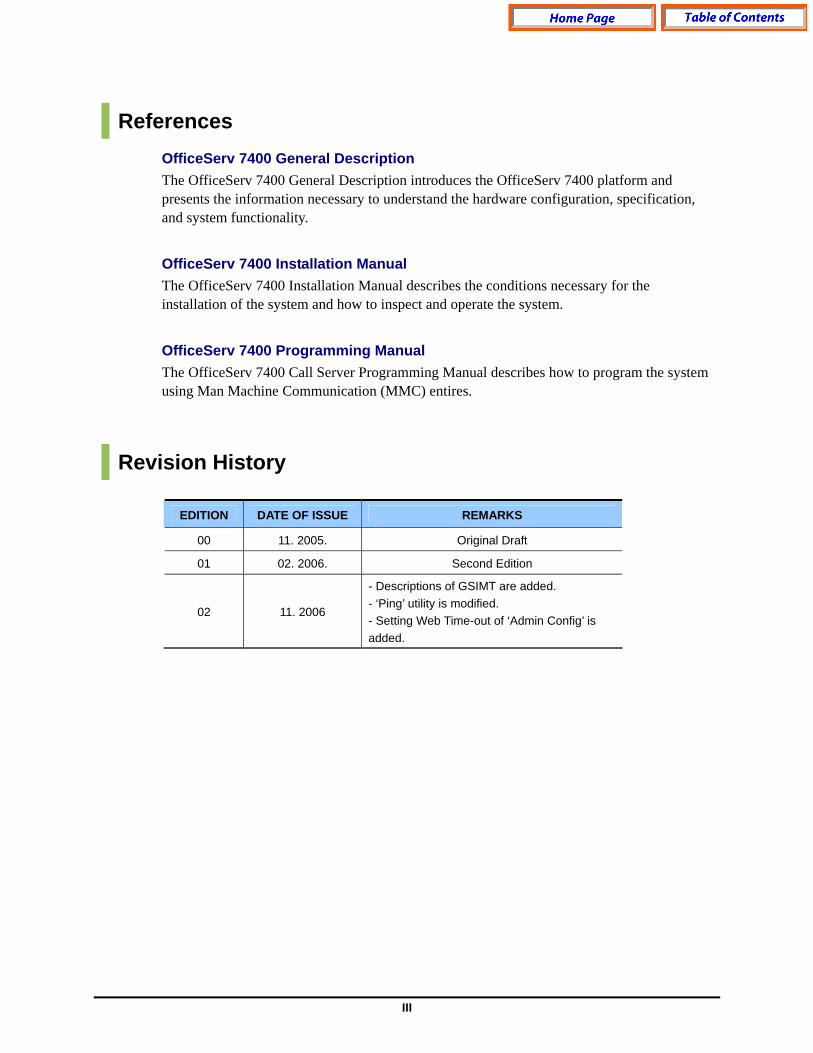
References OfficeServ 7400 General Description The OfficeServ 7400 General Description introduces the OfficeServ 7400 platform and presents the information necessary to understand the hardware configuration, specification, and system functionality.
OfficeServ 7400 Installation Manual The OfficeServ 7400 Installation Manual describes the conditions necessary for the installation of the system and how to inspect and operate the system.
OfficeServ 7400 Programming Manual The OfficeServ 7400 Call Server Programming Manual describes how to program the system using Man Machine Communication (MMC) entires.
Revision History
EDITION DATE OF ISSUE REMARKS
00 11. 2005. Original Draft
01 02. 2006. Second Edition
02 11. 2006
- Descriptions of GSIMT are added. - ‘Ping’ utility is modified. - Setting Web Time-out of ‘Admin Config’ is added.

IV
SAFETY CONCERNS In order to ensure product safety and proper operation, information followed by the following icons should be carefully read before installing or using the product:
Symbols
Caution
Indication of a general caution.
Restriction
Indication for prohibiting an action for a product.
Instruction
Indication for commanding a specifically required action.
V
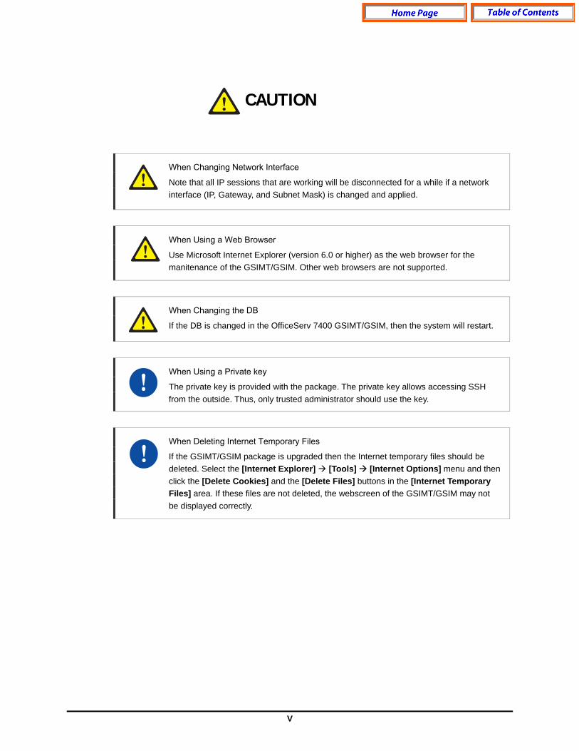
Caution
When Changing Network Interface
Note that all IP sessions that are working will be disconnected for a while if a network interface (IP, Gateway, and Subnet Mask) is changed and applied.
When Using a Web Browser
Use Microsoft Internet Explorer (version 6.0 or higher) as the web browser for the manitenance of the GSIMT/GSIM. Other web browsers are not supported.
When Changing the DB
If the DB is changed in the OfficeServ 7400 GSIMT/GSIM, then the system will restart.
When Using a Private key
The private key is provided with the package. The private key allows accessing SSH from the outside. Thus, only trusted administrator should use the key.
When Deleting Internet Temporary Files
If the GSIMT/GSIM package is upgraded then the Internet temporary files should be deleted. Select the [Internet Explorer] [Tools] [Internet Options] menu and then click the [Delete Cookies] and the [Delete Files] buttons in the [Internet Temporary Files] area. If these files are not deleted, the webscreen of the GSIMT/GSIM may not be displayed correctly.
CAUTION
VI
TABLE OF CONTENTS
INTRODUCTION I
Purpose .......................................................................................................................... I Document Content and Organization.............................................................................. I Conventions................................................................................................................... II Console Screen Output ................................................................................................. II References ................................................................................................................... III Revision History............................................................................................................ III
SAFETY CONCERNS IV
Symbols ........................................................................................................................IV Caution ..........................................................................................................................V
CHAPTER 1. Overview of OfficeServ 7400 GSIMT/GSIM 8
Introduction to OfficeServ 7400 ........................................................................................ 8 Introduction to OfficeServ 7400 GSIMT/GSIM.................................................................. 9
CHAPTER 2. Installation of OfficeServ 7400 GSIMT/GSIM 11
Software Installation......................................................................................................... 11 Getting Started.................................................................................................................. 13
CHAPTER 3. USING OS 7400 GSIMT/GSIM 15
Port Menu.......................................................................................................................... 16 PORT...........................................................................................................................17 VLAN ...........................................................................................................................21
Layer2 Menu...................................................................................................................... 25 RSTP ...........................................................................................................................26 Port Aggregation .......................................................................................................... 29 GVRP .......................................................................................................................... 31 IGMP Snooping ........................................................................................................... 33 Authentication .............................................................................................................. 36
VII
Interface ............................................................................................................................ 38 IP Configuration ........................................................................................................... 38 DNS ............................................................................................................................. 39 Status........................................................................................................................... 40 Utility............................................................................................................................ 41
Layer 3 Menu..................................................................................................................... 43 General ........................................................................................................................44 Configuration ............................................................................................................... 45 List ............................................................................................................................... 55 Status........................................................................................................................... 63
IPMC .................................................................................................................................. 67 General ........................................................................................................................68 Configuration ............................................................................................................... 69 Status........................................................................................................................... 77
QoS Menu.......................................................................................................................... 79 Ingress Service ............................................................................................................ 79 Egress Service............................................................................................................. 89
Application Menu.............................................................................................................. 91 VoIP Service Menu ...................................................................................................... 92 DHCP Server ............................................................................................................... 93 DHCP Relay Agent ...................................................................................................... 96
System Menu ....................................................................................................................97 DB Config .................................................................................................................... 98 Admin Config ............................................................................................................... 98 Log............................................................................................................................. 100 Time Configuration..................................................................................................... 102 Upgrade..................................................................................................................... 104 Appl Server ................................................................................................................ 104 Reboot ....................................................................................................................... 105
Management Menu ......................................................................................................... 106 SNMP ........................................................................................................................ 107 RMON........................................................................................................................ 110
My Info Menu................................................................................................................... 113 ABBREVIATION .............................................................................................................. 114
A ~ L .......................................................................................................................... 114 N ~ V.......................................................................................................................... 115
8
CHAPTER 1. Overview of OfficeServ 7400 GSIMT/GSIM This chapter introduces the OfficeServ 7400 system and OfficeServ 7400 GSIMT/GSIM L2/3 Switch.
Introduction to OfficeServ 7400 The OfficeServ 7400 platform delivers the convergence of voice, data, wired and wireless communications for small and medium sized businesses. This ‘office in a box’ solution offers TDM voice processing, voice over IP integration, wireless communications, voice mail, computer telephony integration, data router and switching functions, all in one powerful platform. With the GSIMT/GSIM, GPLIMT/GPLIM, and GSIMT/GSIM Data Modules, the OfficeServ 7400 provides network functions such as a gigabit switching, Power Over Ethernet, high speed data routing, and network security in a single converged solution. This document describes the data and routing capabilities of the OfficeServ 7400 GSIMT/GSIM L2/3 Switch.
Structure of OfficeServ 7400
For the information on the structure, features, or specifications of the OfficeServ 7400, refer to the ‘OfficeServ 7400 General Description’.
9
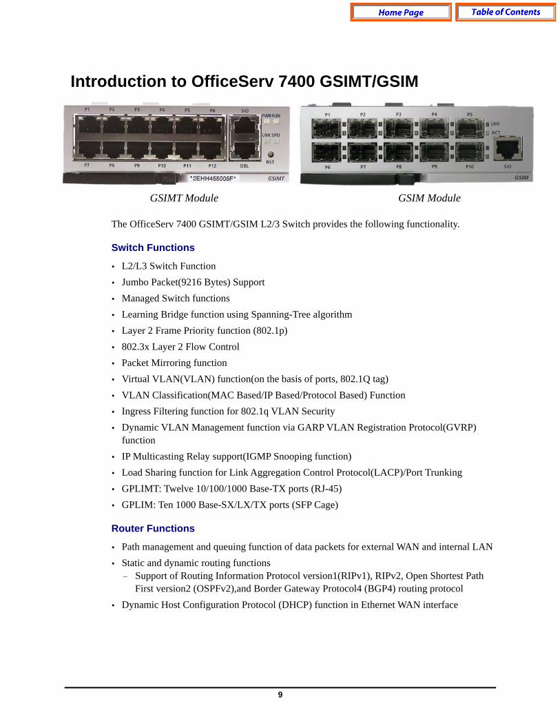
Introduction to OfficeServ 7400 GSIMT/GSIM
GSIMT Module GSIM Module The OfficeServ 7400 GSIMT/GSIM L2/3 Switch provides the following functionality.
Switch Functions
L2/L3 Switch Function Jumbo Packet(9216 Bytes) Support Managed Switch functions Learning Bridge function using Spanning-Tree algorithm Layer 2 Frame Priority function (802.1p) 802.3x Layer 2 Flow Control Packet Mirroring function Virtual VLAN(VLAN) function(on the basis of ports, 802.1Q tag) VLAN Classification(MAC Based/IP Based/Protocol Based) Function Ingress Filtering function for 802.1q VLAN Security Dynamic VLAN Management function via GARP VLAN Registration Protocol(GVRP)
function IP Multicasting Relay support(IGMP Snooping function) Load Sharing function for Link Aggregation Control Protocol(LACP)/Port Trunking GPLIMT: Twelve 10/100/1000 Base-TX ports (RJ-45) GPLIM: Ten 1000 Base-SX/LX/TX ports (SFP Cage)
Router Functions
Path management and queuing function of data packets for external WAN and internal LAN Static and dynamic routing functions − Support of Routing Information Protocol version1(RIPv1), RIPv2, Open Shortest Path
First version2 (OSPFv2),and Border Gateway Protocol4 (BGP4) routing protocol Dynamic Host Configuration Protocol (DHCP) function in Ethernet WAN interface
10
Support of IP Multicasting − Support of Internet Group Management Protocol version1 (IGMPv1) and IGMPv2
protocol − Support of Distance Vector Multicast Routing Protocol(DVMRP) and Protocol
Independent Multicast-Sparse Mode (PIM-SM) Multicast Route Protocol
Data Network Application Functions
DHCP Server function − Auto-set of network environment for IP equipment in another function block of the
OfficeServ 7400 system DHCP Relay function − Connection of IP equipment in another function block of the OfficeServ 7400 system to
an external DHCP server to enable to automatically set network environment.
QoS Functions
Priority process for layer 2 frame under 802.1p standard(Switch function) Priority queuing process for layer 3 packets and priority queuing for a specified IP. Priority queuing process for layer 4 packets and priority for Real-time Transport
Protocol(RTP) packets(UDP/TCP port)
Management Functions
Configuration and verification functions for the operations of GSIMT/GSIM functional block via a browser
Configuration and verification functions for the operations of GSIMT/GSIM functional block via the Simple Network Management Protocol(SNMP)
4-Real-time Monitoring(4RMON) function System monitoring and management via the system log function System synchronization function via Network Time Protocol(NTP) Program Upgrade − Program upgrade via TFTP − Program upgrade via HTTP − Program upgrade via Local manager’s PC

11
CHAPTER 2. Installation of OfficeServ 7400 GSIMT/GSIM This chapter describes the installation and the login procedure for OfficeServ 7400 GSIMT/GSIM.
Software Installation OfficeServ 7400 software is installed on GWIM board. The software package is composed of items described below:
Package File Description
Bootrom Package
GSIMT/GSIM-bootldr.img-vx.xx GSIMT/GSIM-bootldr.img-vx.xx.sum
Boot ROM program
GSIMT/GSIM-pkg-vx.xx.tar.gz
Upgrade package for HTTP
GSIMT/GSIM-os..img-vx.xx ‘os’ partition upgrade package for TFTP
GSIMT/GSIM-firmware.img-vx.xx
‘Firmware’ partition upgrade package for TFTP
GSIMT/GSIM-configdb.img-vx.xx
‘configdb’ partition upgrade package for TFTP
GSIMT/GSIM-logdb.img-vx.xx
‘logdb’ partition upgrade package for TFTP
GSIMT/GSIM-flash1.img-vx.xx GSIMT/GSIM-flash1.img-vx.xx.sum
Fusing file for the first flash memory
Main Package
GSIMT/GSIM-flash2.img-vx.xx GSIMT/GSIM-flash2.img-vx.xx.sum
Fusing file for the second flash memory
12
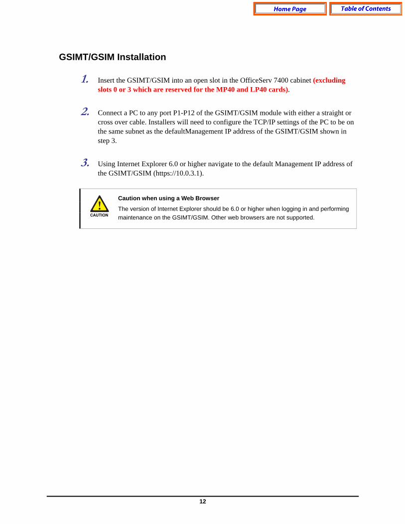
GSIMT/GSIM Installation 1. Insert the GSIMT/GSIM into an open slot in the OfficeServ 7400 cabinet (excluding
slots 0 or 3 which are reserved for the MP40 and LP40 cards). 2. Connect a PC to any port P1-P12 of the GSIMT/GSIM module with either a straight or
cross over cable. Installers will need to configure the TCP/IP settings of the PC to be on the same subnet as the defaultManagement IP address of the GSIMT/GSIM shown in step 3.
3. Using Internet Explorer 6.0 or higher navigate to the default Management IP address of
the GSIMT/GSIM (https://10.0.3.1).
Caution when using a Web Browser
The version of Internet Explorer should be 6.0 or higher when logging in and performing maintenance on the GSIMT/GSIM. Other web browsers are not supported.

13
Getting Started 1. Start Internet Explorer and enter the Management IP address of the GSIMT/GSIM into
the address bar (https://10.0.3.1). The Security Alert window shown below will appear. Click on the Yes button to proceed:
2. A Security Information window will now open. Click on the Yes button to proceed. 3. The Administrator will now be prompted for a Login ID and Password.
The Login ID is “admin” and the default password is “root”.

14
4. Log into the GSIMT/GSIM using the administrator ID and password and then click on the OK button. The following Security Information window will appear again. Click on the Yes button to proceed.
5. The GSIMT/GSIM menus are displayed in the upper part of the screen. Select each
menu to display its submenus on the left section of the screen. For more detailed information for each menu, refer to ‘Chapter 3. Using OfficeServ 7400 GSIMT/GSIM’ of this document
6. Click the [Logout] button on the upper section of the screen to close the connection to the GSIMT/GSIM system.

15
CHAPTER 3. USING OS 7400 GSIMT/GSIM This chapter describes how to use the menus of OfficeServ 7400 GSIMT/GSIM.
The configuration of OfficeServ 7400 GSIMT/GSIM menus is as follows:
16
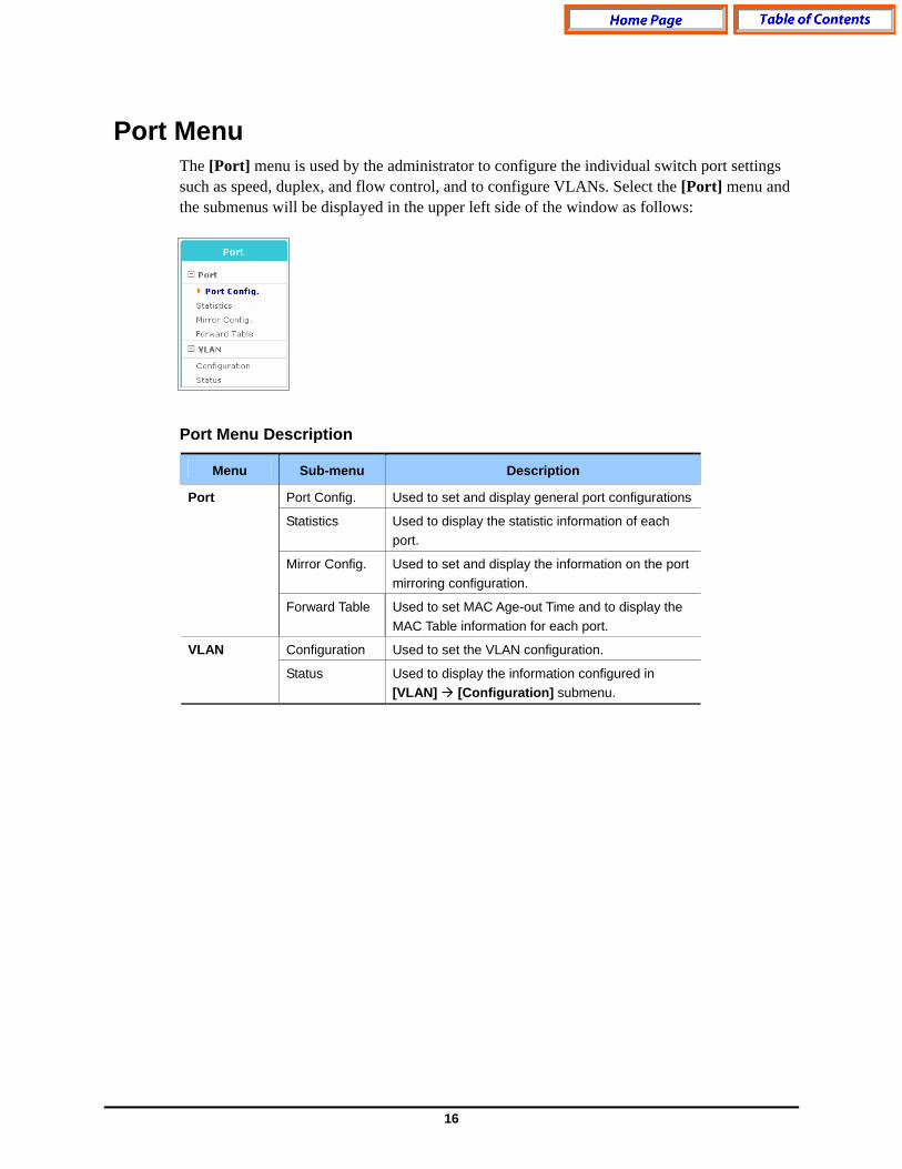
Port Menu The [Port] menu is used by the administrator to configure the individual switch port settings such as speed, duplex, and flow control, and to configure VLANs. Select the [Port] menu and the submenus will be displayed in the upper left side of the window as follows: Port Menu Description
Menu Sub-menu Description
Port Config. Used to set and display general port configurations
Statistics Used to display the statistic information of each port.
Mirror Config. Used to set and display the information on the port mirroring configuration.
Port
Forward Table Used to set MAC Age-out Time and to display the MAC Table information for each port.
Configuration Used to set the VLAN configuration. VLAN
Status Used to display the information configured in [VLAN] [Configuration] submenu.
17
PORT The [Port] [Port] submenu is used to set the functionality of the switch ports, to retrieve configuration information on the switch ports, to set up port mirroring, and to adjust the MAC Age-out Timer.
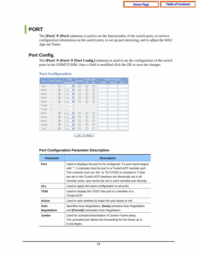
Port Config. The [Port] [Port] [Port Config.] submenu is used to set the configuration of the switch ports in the GSIMT/GSIM. Once a field is modified click the OK to save the changes. Port Configuration Parameter Description
Parameter Description
Port Used to displays the port to be configured. If a port name begins with ‘*’, it indicates that the port is a Trunk/LACP member port. The contents such as ‘Sa*’ or ‘Po*’(TGID is included in *) that are set in the Trunk/LACP Interface are identically set in all member ports, and cannot be set in each member port directly.
ALL Used to apply the same configuration to all ports.
TGID Used to display the TGID f the port is a member of a Trunk/LACP.
Active Used to sets whether to make the port active or not
Auto Negotiation
Specifies Auto Negotiation. [Auto] activates Auto Negotiation and [Forced] inactivates Auto Negotiation.
Jumbo Used for activation/inactivation of Jumbo Frame setup. The activated port allows the forwarding for the frame up to 9,216 Bytes.
18
Parameter Description
Flow Ctrl Used to set whether to perform the Flow Control, and is divided into Tx and Rx.
Storm Ctrl Used to set whether to perform the Storm Control, and is divided into Bcast (Broadcast), Mcast (Multicast), and DLF (Destination Lookup Failure).
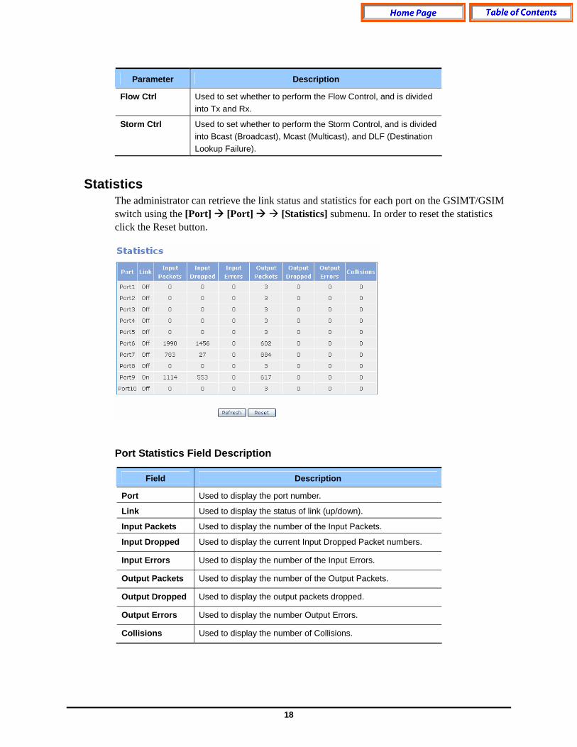
Statistics The administrator can retrieve the link status and statistics for each port on the GSIMT/GSIM switch using the [Port] [Port] [Statistics] submenu. In order to reset the statistics click the Reset button. Port Statistics Field Description
Field Description
Port Used to display the port number.
Link Used to display the status of link (up/down).
Input Packets Used to display the number of the Input Packets.
Input Dropped Used to display the current Input Dropped Packet numbers.
Input Errors Used to display the number of the Input Errors.
Output Packets Used to display the number of the Output Packets.
Output Dropped Used to display the output packets dropped.
Output Errors Used to display the number Output Errors.
Collisions Used to display the number of Collisions.
19
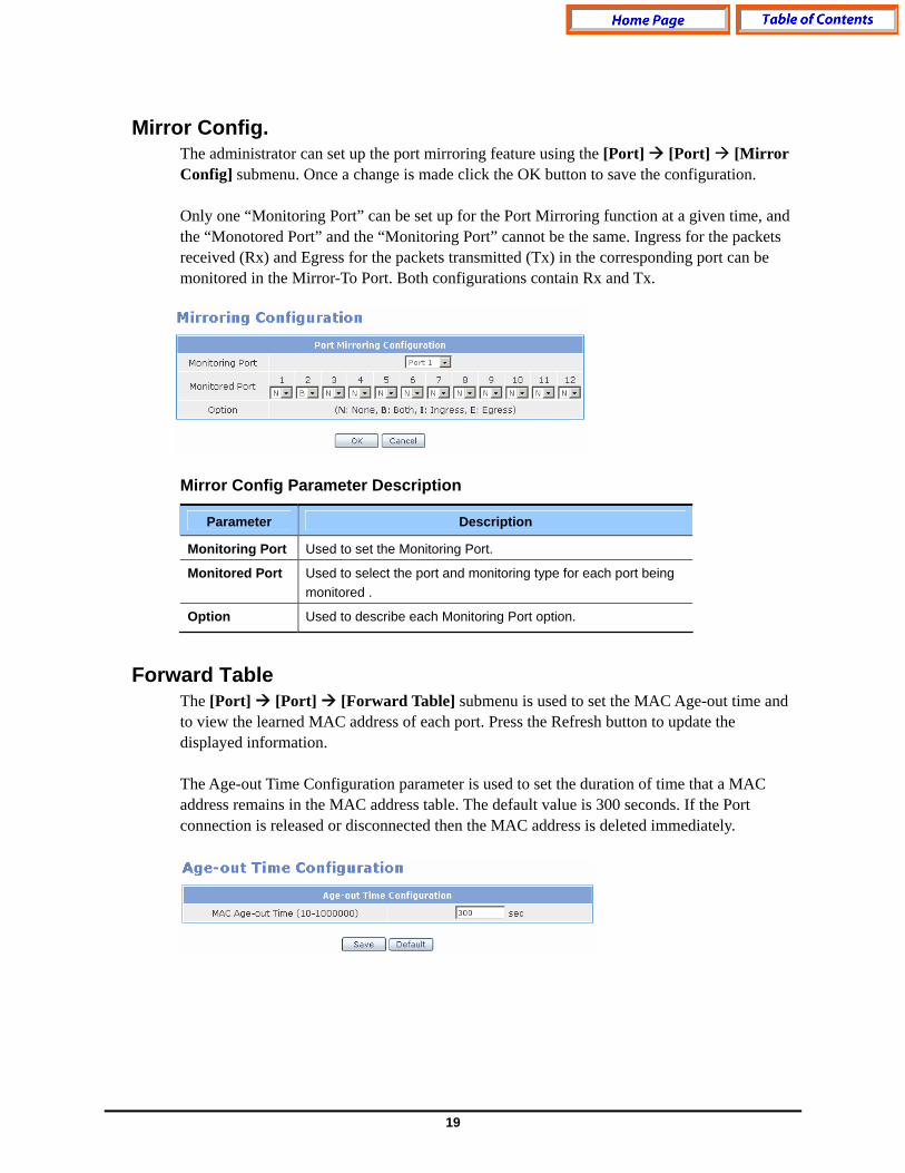
Mirror Config. The administrator can set up the port mirroring feature using the [Port] [Port] [Mirror Config] submenu. Once a change is made click the OK button to save the configuration. Only one “Monitoring Port” can be set up for the Port Mirroring function at a given time, and the “Monotored Port” and the “Monitoring Port” cannot be the same. Ingress for the packets received (Rx) and Egress for the packets transmitted (Tx) in the corresponding port can be monitored in the Mirror-To Port. Both configurations contain Rx and Tx. Mirror Config Parameter Description
Parameter Description
Monitoring Port Used to set the Monitoring Port.
Monitored Port Used to select the port and monitoring type for each port being monitored .
Option Used to describe each Monitoring Port option.
Forward Table The [Port] [Port] [Forward Table] submenu is used to set the MAC Age-out time and to view the learned MAC address of each port. Press the Refresh button to update the displayed information. The Age-out Time Configuration parameter is used to set the duration of time that a MAC address remains in the MAC address table. The default value is 300 seconds. If the Port connection is released or disconnected then the MAC address is deleted immediately.

20
The Forward Table window displays the MAC address information discovered for each port. Forward Table Field Description
Field Description
Port Used to display the port number.
VLAN Used to display the VLAN assignment for the port.
MAC Used to display the learned MAC Address.
MAC Type Used to display the MAC type.
Learn Type Used to display the Learn Type of MAC address.

21
VLAN VLANs are used to divide a network into smaller networks to reduce the traffic and for security purposes. The [Port] [VLAN] submenu is used to configure and view VLANS, Port VIDs, and VLAN Classifications.
Configuration Using the [Port] [VLAN] [Configuration] submenu the administrator can configure the VLAN features. The Port Setup fields are used to configure the VLAN ID for each port and the Ingress Filter for VLAN Security. The type of packets coming from the port can be limited via the Frame-Type. If the port is configured as Tagged-Packet and an Untagged-packet enters the port then the packet is discarded. Port Setup Parameter Description
Categories Description
Port ID Used to select the port to be configured.
PVID Used to specify the default VLAN IN of a port. The ID can be selected from the currently configured VLAN.
Ingress-Filter Used to set the use of Ingress Filtering (Enable/Disable).
Frame Type Used to set the Ingress Packet. (All-Packet/Tagged-Packet).
The VLAN Create field is used to create a VLAN ID. Once a new VLAN-ID is entered click the Save button.
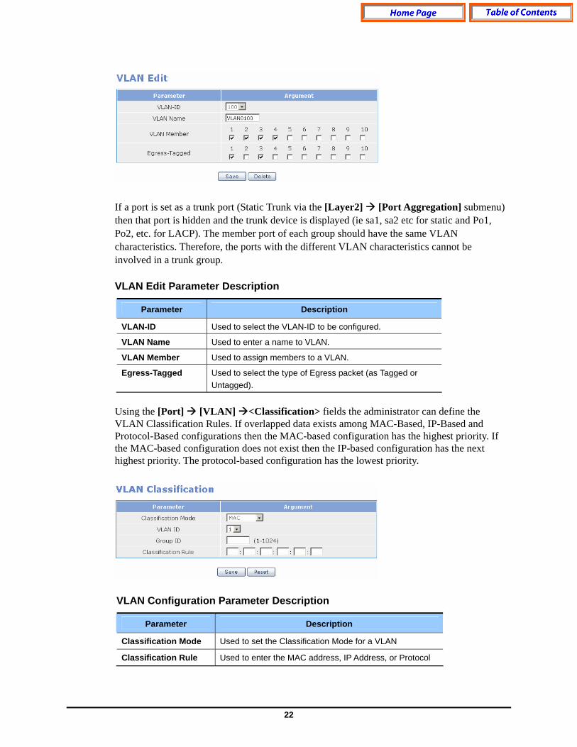
The VLAN Edit fields are used to add or delete members to/from the created VLANs. If a port is defined as Egress-Tagged then the packet sent out through that port is sent out as a Tagged-Packet. To delete a VLAN select the VLAN-ID using the pull down menu and then click the Delete button.
22
If a port is set as a trunk port (Static Trunk via the [Layer2] [Port Aggregation] submenu) then that port is hidden and the trunk device is displayed (ie sa1, sa2 etc for static and Po1, Po2, etc. for LACP). The member port of each group should have the same VLAN characteristics. Therefore, the ports with the different VLAN characteristics cannot be involved in a trunk group. VLAN Edit Parameter Description
Parameter Description
VLAN-ID Used to select the VLAN-ID to be configured.
VLAN Name Used to enter a name to VLAN.
VLAN Member Used to assign members to a VLAN.
Egress-Tagged Used to select the type of Egress packet (as Tagged or Untagged).
Using the [Port] [VLAN] <Classification> fields the administrator can define the VLAN Classification Rules. If overlapped data exists among MAC-Based, IP-Based and Protocol-Based configurations then the MAC-based configuration has the highest priority. If the MAC-based configuration does not exist then the IP-based configuration has the next highest priority. The protocol-based configuration has the lowest priority.
VLAN Configuration Parameter Description
Parameter Description
Classification Mode Used to set the Classification Mode for a VLAN
Classification Rule Used to enter the MAC address, IP Address, or Protocol

23
Parameter Description
Group ID Used to enter a Group ID Valid groups numbers are 1~1024.
VLAN ID Used to set the VLAN ID.
MAC based VLAN If MAC is selected as the classification mode then the VLAN Configuration window is displayed as follows. This window is used for the configuration of VLAN in accordance with the source MAC address of the Untagged packet arriving to the port.
IP Based VLAN IF IP-Subnet is selected as the classification mode then the VLAN Configuration window is displayed as follows. This window is used to configure VLAN depending on the IP subnet of the Untagged packet coming in the port. Protocol Based VLAN If Protocol is selected as the classification mode then the following VLAN configuration window is displayed as follows. This window is used to configure VLAN depending on the protocol type of the Untagged packet coming into the corresponding port. In the Classification Rule a protocol can be selected and a user can enter the protocol number as hexadecimal value. If the port is set as the trunk group then the same setting is to be made in all member ports of the trunk group.
24
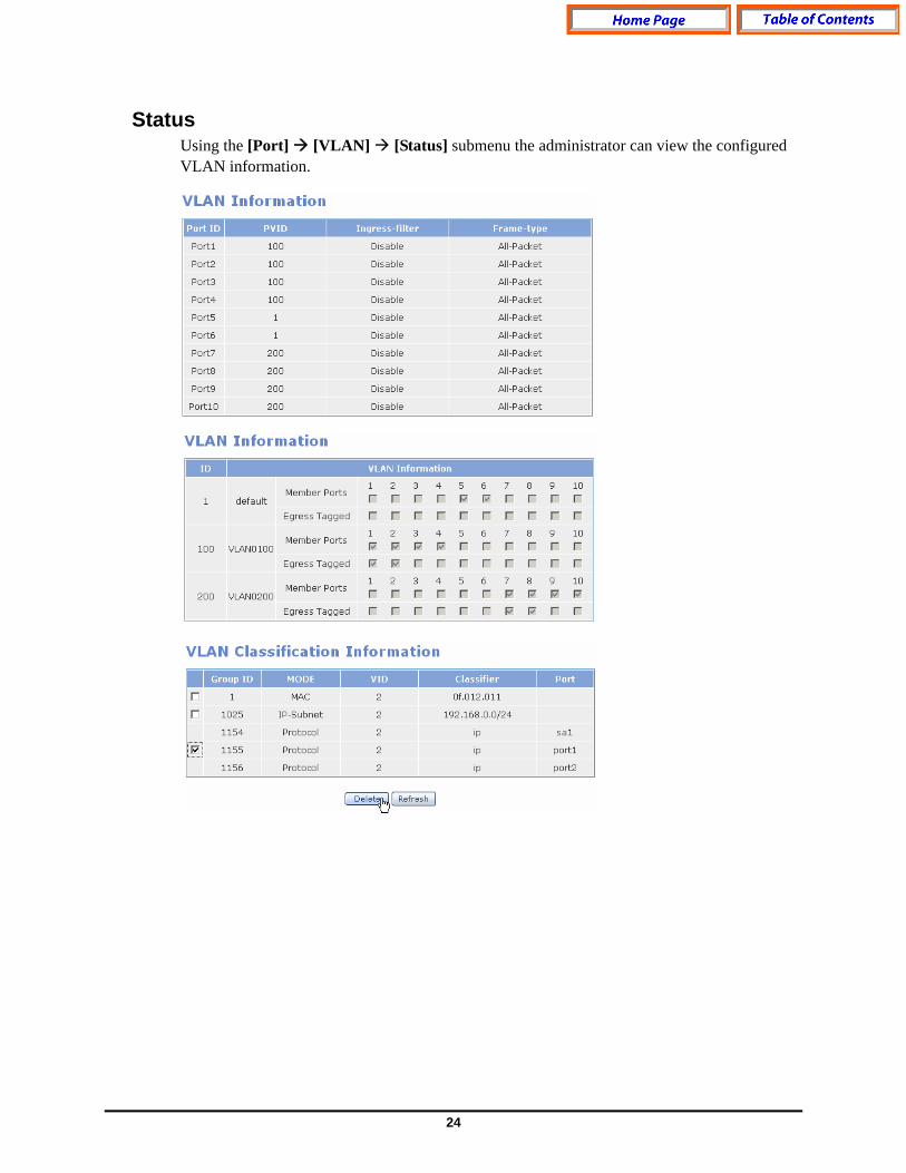
Status Using the [Port] [VLAN] [Status] submenu the administrator can view the configured VLAN information.

25
Layer2 Menu The Layer 2 Menu is used to configure the Spanning Tree Protocol, GVRP, IGMP, and port based authentication. Once the [Layer2] menu is selected the submenus will be displayed in the upper left side of the window as follows: Layer 2 Menu Description
Menu Submenu Description
Configuration Used to set the bridge and port environment used in RSTP. RSTP
Status Used to display the RSTP operation status of the switch.
Configuration Used to set the Port Aggregation related values Port Aggregation
Status Used to display the Port Aggregation values
Configuration Used to set up the GVRP and Dynamic VLAN Creation services.
GVRP
Status Used to display the status of each port where GVRP is set.
Time Interval Used to set the time interval for IGMP Snooping.
Function Used to set the function related with IGMP Snooping.
Forwarding Table
Used to display the information for the members registered in IGMP Group.
IGMP Snooping
Management Used to set whether to operate IGMP Snooping.
Configuration Used to set the Authentication service. Authentication
Management Used to start or stop the Authentication service.
26
RSTP
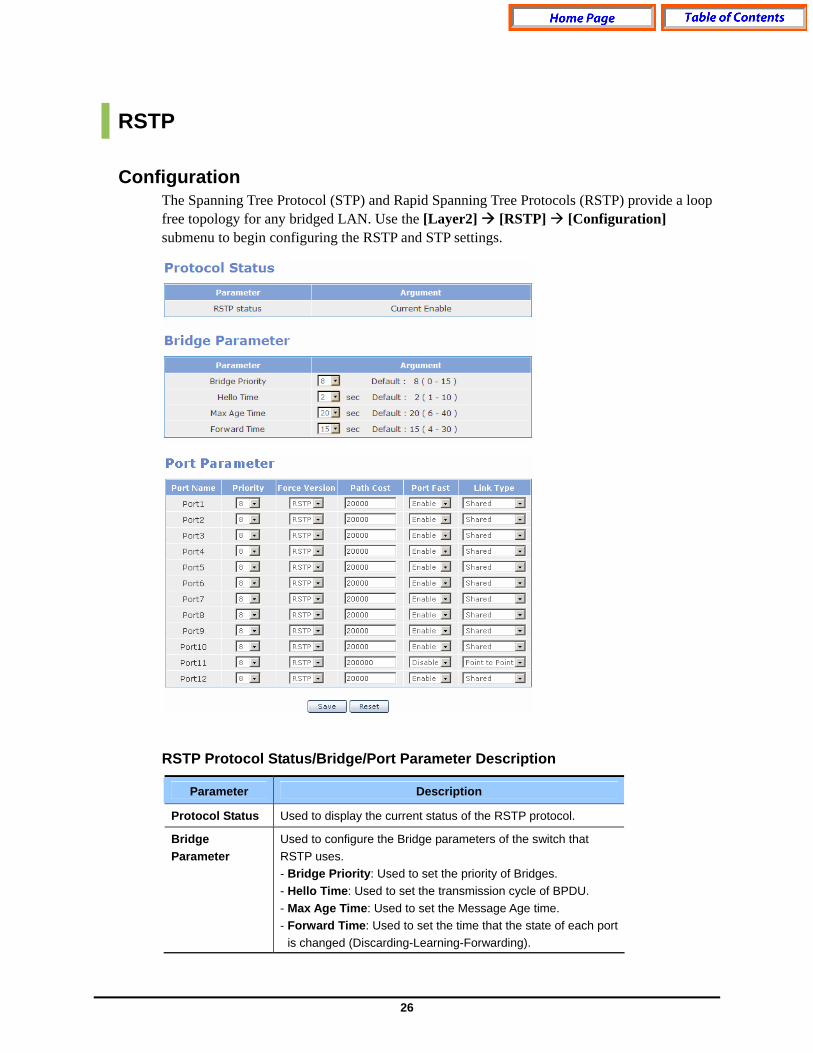
Configuration The Spanning Tree Protocol (STP) and Rapid Spanning Tree Protocols (RSTP) provide a loop free topology for any bridged LAN. Use the [Layer2] [RSTP] [Configuration] submenu to begin configuring the RSTP and STP settings.
RSTP Protocol Status/Bridge/Port Parameter Description
Parameter Description
Protocol Status Used to display the current status of the RSTP protocol.
Bridge Parameter
Used to configure the Bridge parameters of the switch that RSTP uses. - Bridge Priority: Used to set the priority of Bridges. - Hello Time: Used to set the transmission cycle of BPDU. - Max Age Time: Used to set the Message Age time. - Forward Time: Used to set the time that the state of each port
is changed (Discarding-Learning-Forwarding).
27
Parameter Description
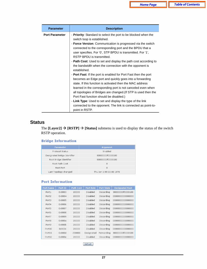
Port Parameter - Priority: Standard to select the port to be blocked when the switch loop is established.
- Force Version: Communication is progressed via the switch connected to the corresponding port and the BPDU that a user specifies. For ‘0’, STP BPDU is transmitted. For ‘1’, RSTP BPDU is transmitted.
- Path Cost: Used to set and display the path cost according to the bandwidth when the connection with the opponent is established.
- Port Fast: If the port is enabled for Port Fast then the port becomes an Edge port and quickly goes into a forwarding state. If this function is activated then the MAC address learned in the corresponding port is not canceled even when all topologies of Bridges are changed.(If STP is used then the Port Fast function should be disabled.)
- Link Type: Used to set and display the type of the link connected to the opponent. The link is connected as point-to-point in RSTP.
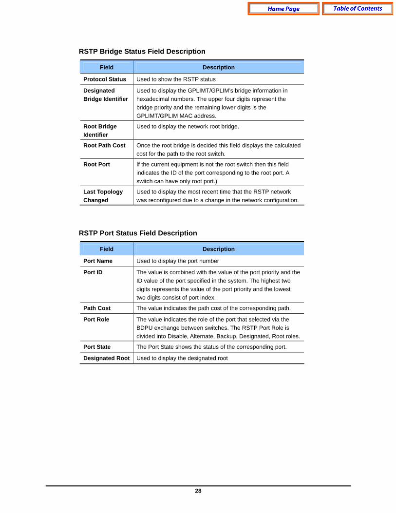
Status The [Layer2] [RSTP] [Status] submenu is used to display the status of the switch RSTP operation.
28
RSTP Bridge Status Field Description
Field Description
Protocol Status Used to show the RSTP status
Designated Bridge Identifier
Used to display the GPLIMT/GPLIM’s bridge information in hexadecimal numbers. The upper four digits represent the bridge priority and the remaining lower digits is the GPLIMT/GPLIM MAC address.
Root Bridge Identifier
Used to display the network root bridge.
Root Path Cost Once the root bridge is decided this field displays the calculated cost for the path to the root switch.
Root Port If the current equipment is not the root switch then this field indicates the ID of the port corresponding to the root port. A switch can have only root port.)
Last Topology Changed
Used to display the most recent time that the RSTP network was reconfigured due to a change in the network configuration.
RSTP Port Status Field Description
Field Description
Port Name Used to display the port number
Port ID The value is combined with the value of the port priority and the ID value of the port specified in the system. The highest two digits represents the value of the port priority and the lowest two digits consist of port index.
Path Cost The value indicates the path cost of the corresponding path.
Port Role The value indicates the role of the port that selected via the BDPU exchange between switches. The RSTP Port Role is divided into Disable, Alternate, Backup, Designated, Root roles.
Port State The Port State shows the status of the corresponding port.
Designated Root Used to display the designated root
29
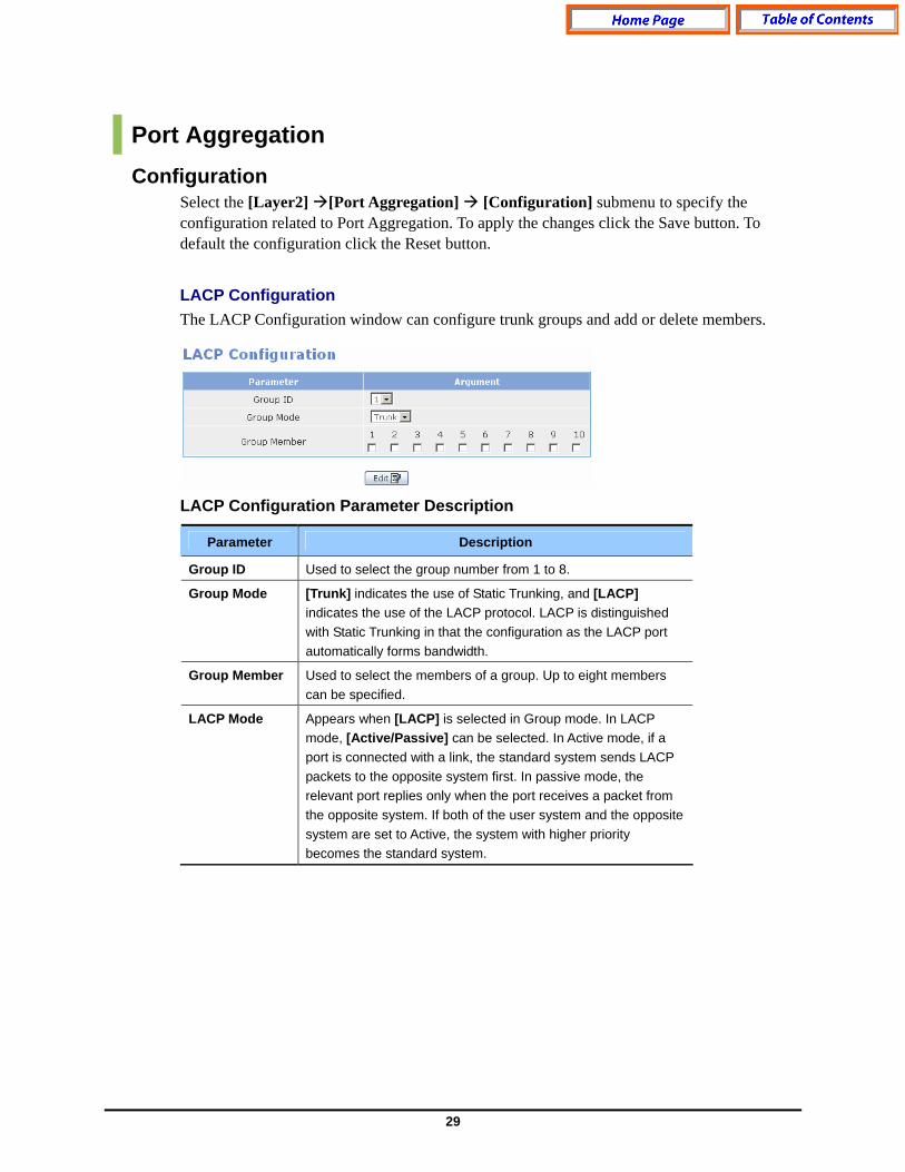
Port Aggregation Configuration
Select the [Layer2] [Port Aggregation] [Configuration] submenu to specify the configuration related to Port Aggregation. To apply the changes click the Save button. To default the configuration click the Reset button.
LACP Configuration The LACP Configuration window can configure trunk groups and add or delete members. LACP Configuration Parameter Description
Parameter Description
Group ID Used to select the group number from 1 to 8.
Group Mode [Trunk] indicates the use of Static Trunking, and [LACP] indicates the use of the LACP protocol. LACP is distinguished with Static Trunking in that the configuration as the LACP port automatically forms bandwidth.
Group Member Used to select the members of a group. Up to eight members can be specified.
LACP Mode Appears when [LACP] is selected in Group mode. In LACP mode, [Active/Passive] can be selected. In Active mode, if a port is connected with a link, the standard system sends LACP packets to the opposite system first. In passive mode, the relevant port replies only when the port receives a packet from the opposite system. If both of the user system and the opposite system are set to Active, the system with higher priority becomes the standard system.
30
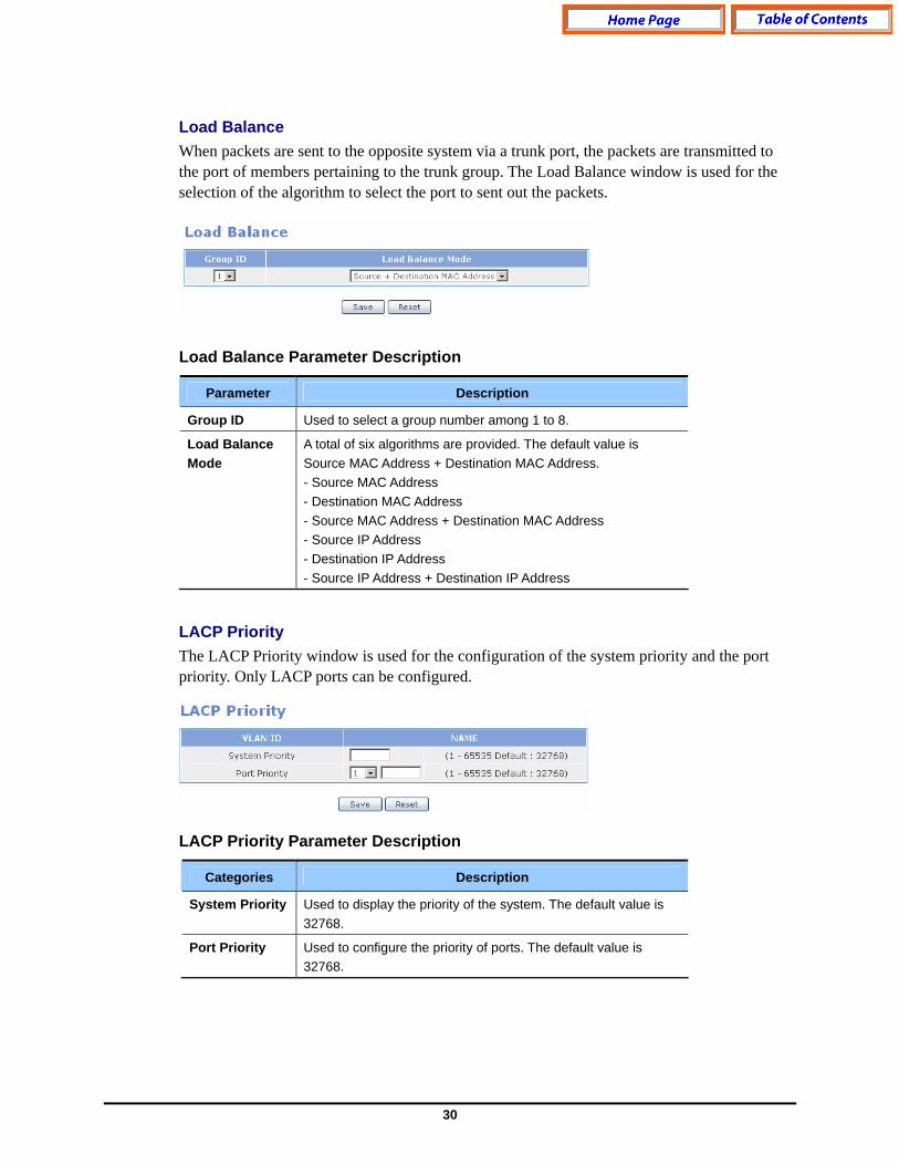
Load Balance When packets are sent to the opposite system via a trunk port, the packets are transmitted to the port of members pertaining to the trunk group. The Load Balance window is used for the selection of the algorithm to select the port to sent out the packets. Load Balance Parameter Description
Parameter Description
Group ID Used to select a group number among 1 to 8.
Load Balance Mode
A total of six algorithms are provided. The default value is Source MAC Address + Destination MAC Address. - Source MAC Address - Destination MAC Address - Source MAC Address + Destination MAC Address - Source IP Address - Destination IP Address - Source IP Address + Destination IP Address
LACP Priority The LACP Priority window is used for the configuration of the system priority and the port priority. Only LACP ports can be configured. LACP Priority Parameter Description
Categories Description
System Priority Used to display the priority of the system. The default value is 32768.
Port Priority Used to configure the priority of ports. The default value is 32768.
31
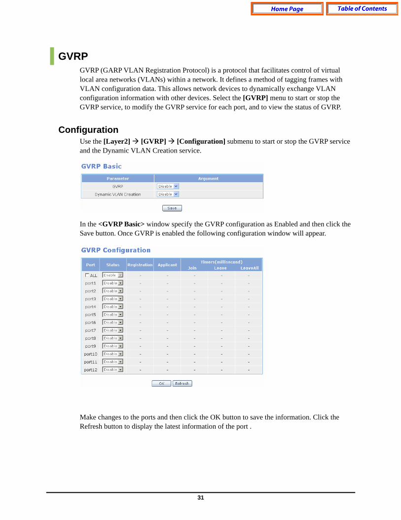
GVRP GVRP (GARP VLAN Registration Protocol) is a protocol that facilitates control of virtual local area networks (VLANs) within a network. It defines a method of tagging frames with VLAN configuration data. This allows network devices to dynamically exchange VLAN configuration information with other devices. Select the [GVRP] menu to start or stop the GVRP service, to modify the GVRP service for each port, and to view the status of GVRP.
Configuration Use the [Layer2] [GVRP] [Configuration] submenu to start or stop the GVRP service and the Dynamic VLAN Creation service. In the <GVRP Basic> window specify the GVRP configuration as Enabled and then click the Save button. Once GVRP is enabled the following configuration window will appear. Make changes to the ports and then click the OK button to save the information. Click the Refresh button to display the latest information of the port .

32
GVRP Configuration Field/Parameter Description
Field/Parameter Description
Port Used to display the port Number
Status Used to enable or disable GVRP per port
Registration Used to display the Registration mode as Normal, Forbidden or Fixed
Applicant Used to display the Applicant mode as Normal or Active conditions
Join Used to display the interval for Join Transfer Time
Leave Used to display the value of Leave Delay Time
LeaveAll Used to display the value of LeaveAll Transfer Time
Status The [Layer2] [GVRP] [Status] submenu is used to display the information on the ports where GVRP is configured.
GVRP Machine Field Description
Field Description
Port Used to display the Port Number
Applicant State
Used to display the Current Status of the Applicant State Machine
Register State Used to display the Current Status of the Register State Machine

33
GVRP Statistics Field Description
Field Description
Port Used to display the Port Number
Join Empty Used to display the number of Join Empty packets
Join In Used to display the number of Join In packets
Leave Empty Used to display the number of Leave Empty packets
Leave In Used to display the number of Leave In packets
Empty Used to display the number of Empty packets
IGMP Snooping The purpose of Internet Group Management Protocol (IGMP) snooping is to restrain multicast traffic in a switched network. The [Layer2] [IGMP Snooping] menu is used for the configuration of IGMP Snooping.
Time Interval Use the [Layer2] [IGMP Snooping] [Time Interval] submenu to configure the time related parameters of IGMP Snooping. IGMP Time Interval Category Description
Categories Description
VLAN Pull down menu used to select the VLAN to be configured.
Group Membership Used to configure the time to exit from the multicast forwarding database list when new report does not exist.
Last Member Query Used to configure the time to wait a response report after sending a query to check if the host is the last host when multicast router receives a leave message from a host. If the report is not replied until the time is elapsed, the host is deleted from the group.
34
Categories Description
Max Response Used to configure the maximum time until its response when IGMP Snooping query is received.
Other Query Used to configure the time until the operation as a querier starts when a query from the multicast router doest not exist.
Select the VLAN and the Category to configure, enter the timed value, and then click the OK button to store the configuration.
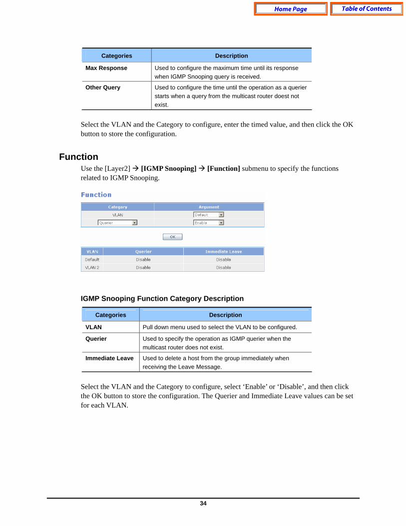
Function Use the [Layer2] [IGMP Snooping] [Function] submenu to specify the functions related to IGMP Snooping. IGMP Snooping Function Category Description
Categories Description
VLAN Pull down menu used to select the VLAN to be configured.
Querier Used to specify the operation as IGMP querier when the multicast router does not exist.
Immediate Leave Used to delete a host from the group immediately when receiving the Leave Message.
Select the VLAN and the Category to configure, select ‘Enable’ or ‘Disable’, and then click the OK button to store the configuration. The Querier and Immediate Leave values can be set for each VLAN.
35
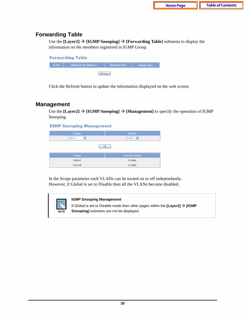
Forwarding Table Use the [Layer2] [IGMP Snooping] [Forwarding Table] submenu to display the information on the members registered in IGMP Group. Click the Refresh button to update the information displayed on the web screen.
Management Use the [Layer2] [IGMP Snooping] [Management] to specify the operation of IGMP Snooping. In the Scope parameter each VLANs can be turned on or off independantly. However, if Global is set to Disable then all the VLANs become disabled.
IGMP Snooping Management
If Global is set to Disable mode then other pages within the [Layer2] [IGMP Snooping] submenu are not be displayed.
36
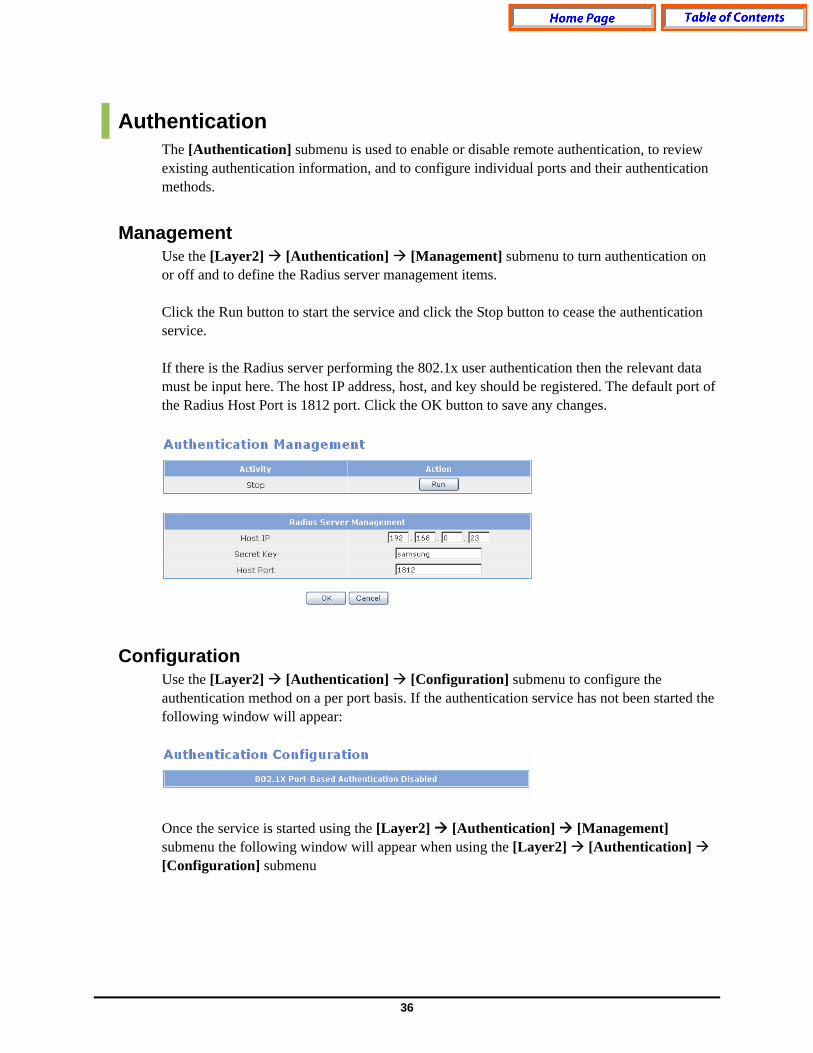
Authentication The [Authentication] submenu is used to enable or disable remote authentication, to review existing authentication information, and to configure individual ports and their authentication methods.
Management Use the [Layer2] [Authentication] [Management] submenu to turn authentication on or off and to define the Radius server management items. Click the Run button to start the service and click the Stop button to cease the authentication service. If there is the Radius server performing the 802.1x user authentication then the relevant data must be input here. The host IP address, host, and key should be registered. The default port of the Radius Host Port is 1812 port. Click the OK button to save any changes.
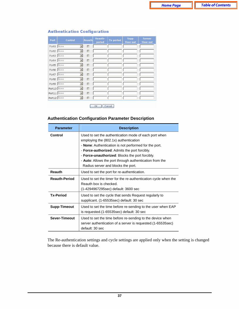
Configuration Use the [Layer2] [Authentication] [Configuration] submenu to configure the authentication method on a per port basis. If the authentication service has not been started the following window will appear: Once the service is started using the [Layer2] [Authentication] [Management] submenu the following window will appear when using the [Layer2] [Authentication] [Configuration] submenu
37
Authentication Configuration Parameter Description
Parameter Description
Control Used to set the authentication mode of each port when employing the (802.1x) authentication - None: Authentication is not performed for the port. - Force-authorized: Admits the port forcibly. - Force-unauthorized: Blocks the port forcibly. - Auto: Allows the port through authentication from the Radius server and blocks the port.
Reauth Used to set the port for re-authentication.
Reauth-Period Used to set the timer for the re-authentication cycle when the Reauth box is checked. (1-4294967295sec) default: 3600 sec
Tx-Period Used to set the cycle that sends Request regularly to supplicant. (1-65535sec) default: 30 sec
Supp-Timeout Used to set the time before re-sending to the user when EAP is requested.(1-65535sec) default: 30 sec
Sever-Timeout Used to set the time before re-sending to the device when server authentication of a server is requested.(1-65535sec) default: 30 sec
The Re-authentication settings and cycle settings are applied only when the setting is changed because there is default value.

38
Interface The [Interface] submenu is used to set up the Management IP address on the GSIMT/GSIM, to enter the DNS server information, to view the status of the network, and to perform ping testing. The [Interface] submenus will be displayed in the upper left side of the window as follows: Interface Menu Description
Menu Submenu Description
IP Configuration - Used to set an IP address of a VLAN .
DNS - Used to sets a name server used in GSIMT/GSIM.
Status - Used to display the IP address or MAC information currently being set in a VLAN device.
Utility Ping Used to check the network by executing a ping test.
IP Configuration This menu is used to set an IP and Administrative up/down.
Network Interface This section of the submenu is used to set the GSIMT/GSIM Management IP address and Netmask information. Enter the new IP address and Netmask information for each VLAN and then click the OK button to save the changes. The default value of the GSIMT/GSIM IP Address is 10.0.3.1/24.
39
Network Interface Parameter Description
Menu Submenu Description
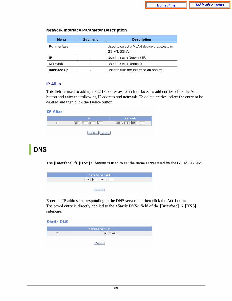
Rd Interface - Used to select a VLAN device that exists in GSIMT/GSIM.
IP - Used to set a Network IP.
Netmask - Used to set a Netmask.
Interface Up - Used to turn the Interface on and off.
IP Alias
This field is used to add up to 32 IP addresses to an Interface. To add entries, click the Add button and enter the following IP address and netmask. To delete entries, select the entry to be deleted and then click the Delete button.
DNS The [Interface] [DNS] submenu is used to set the name server used by the GSIMT/GSIM. Enter the IP address corresponding to the DNS server and then click the Add button. The saved entry is directly applied to the <Static DNS> field of the [Interface] [DNS] submenu.

40
Status This [Interface] [Status] submenu is used to retrieve the Interface information from the GSIMT/GSIM. Status Field Description
Menu Submenu Description
Interface - Used to display the Interface name
IP - IUsed to display the IP address information
Netmask - Used to display the Netmask information
Status - Used to display the whether the interface is activated or deactivated

41
Utility Select the [Interface] [Utility] submenu to perform ping tests on the GSIMT/GSIM.
Ping The Ping window is a table which is used to specify and execute the Ping test. When an administrator selects this submenu the following configuration window is displayed. Ping Parameters
Parameter Description
Destination IP Address
Used to enter the destination IP address for the Ping test
Source Address Used to set the IP address of the interface for the Ping test
Packet Size Used to set the packet size to be transmitted
Retry Count Used to set the retry count. If it set to ‘0’, there is no retry. Max is 3
Time to Live Used to set the TTL value.
42
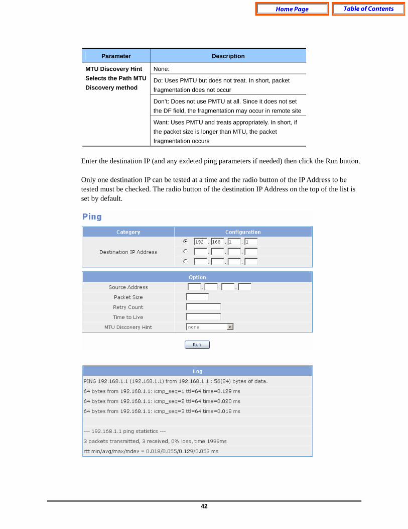
Parameter Description
None:
Do: Uses PMTU but does not treat. In short, packet fragmentation does not occur
Don’t: Does not use PMTU at all. Since it does not set the DF field, the fragmentation may occur in remote site
MTU Discovery Hint Selects the Path MTU Discovery method
Want: Uses PMTU and treats appropriately. In short, if the packet size is longer than MTU, the packet fragmentation occurs
Enter the destination IP (and any exdeted ping parameters if needed) then click the Run button. Only one destination IP can be tested at a time and the radio button of the IP Address to be tested must be checked. The radio button of the destination IP Address on the top of the list is set by default.

43
Layer 3 Menu The [Layer3] menu is used to manage static and dynamic routing for the GSIMT/GSIM. Select the [Layer3] menu to begin configuring the routing statements and routing protocols. The [Layer3] submenus will be displayed in the upper left side of the window as follows:
Layer3 Menu Submenu Description
Menu Submenu Description
Routes Used to display the routing table of GSIMT/GSIM. General
Management Used to start or stop RIP, OSPF, and BGP.
Static Used to set up a static route.
RIP Used to set up RIP.
RIP Interface Used to sets the RIP interface.
OSPF Used to set up OSPF.
OSPF Interface Used to set up the OSPF interface.
Configuration
BGP Used to set up BGP.
44
Menu Submenu Description
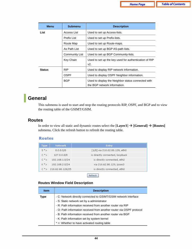
Access List Used to set up Access-lists.
Prefix List Used to set up Prefix-lists.
Route Map Used to set up Route-maps.
As Path List Used to set up BGP AS-path lists.
Community List Used to set up BGP Community-lists.
List
Key Chain Used to set up the key used for authentication of RIP v2.
RIP Used to display RIP network information.
OSPF Used to display OSPF Neighbor information.
Status
BGP Used to display the Neighbor status connected with the BGP network information.
General This submenu is used to start and stop the routing protocols RIP, OSPF, and BGP and to view the routing table of the GSIMT/GSIM.
Routes In order to view all static and dynamic routes select the [Layer3] [General] [Routes] submenu. Click the refresh button to refresh the routing table. Routes Window Field Description
Item Description
Type - C: Network directly connected to GSIMT/GSIM network interface - S: Static network set by a administrator - R: Path information received from another router via RIP - O: Path information received from another router via OSPF protocol - B: Path information received from another router via BGP - K: Path information set by system kernel * >: Whether to have activated routing table
45
Item Description
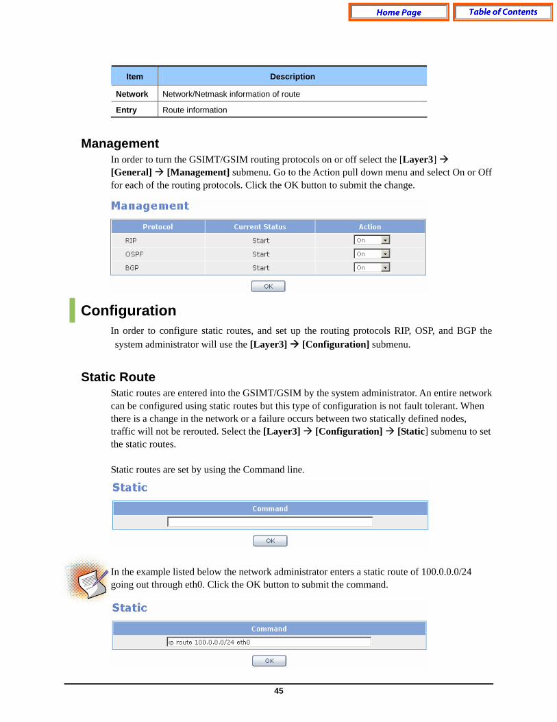
Network Network/Netmask information of route
Entry Route information
Management In order to turn the GSIMT/GSIM routing protocols on or off select the [Layer3] [General] [Management] submenu. Go to the Action pull down menu and select On or Off for each of the routing protocols. Click the OK button to submit the change.
Configuration In order to configure static routes, and set up the routing protocols RIP, OSP, and BGP the system administrator will use the [Layer3] [Configuration] submenu.
Static Route Static routes are entered into the GSIMT/GSIM by the system administrator. An entire network can be configured using static routes but this type of configuration is not fault tolerant. When there is a change in the network or a failure occurs between two statically defined nodes, traffic will not be rerouted. Select the [Layer3] [Configuration] [Static] submenu to set the static routes. Static routes are set by using the Command line.
In the example listed below the network administrator enters a static route of 100.0.0.0/24 going out through eth0. Click the OK button to submit the command.
46
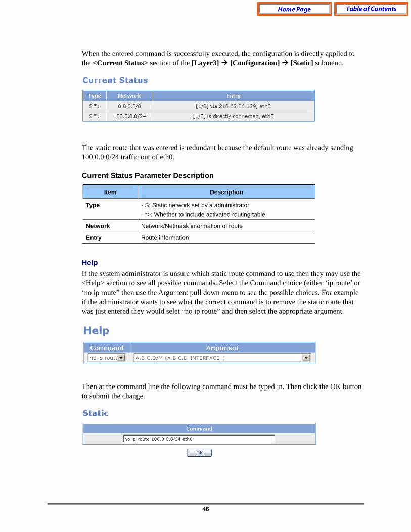
When the entered command is successfully executed, the configuration is directly applied to the <Current Status> section of the [Layer3] [Configuration] [Static] submenu. The static route that was entered is redundant because the default route was already sending 100.0.0.0/24 traffic out of eth0. Current Status Parameter Description
Item Description
Type - S: Static network set by a administrator - *>: Whether to include activated routing table
Network Network/Netmask information of route
Entry Route information
Help If the system administrator is unsure which static route command to use then they may use the <Help> section to see all possible commands. Select the Command choice (either ‘ip route’ or ‘no ip route” then use the Argument pull down menu to see the possible choices. For example if the administrator wants to see whet the correct command is to remove the static route that was just entered they would selet “no ip route” and then select the appropriate argument. Then at the command line the following command must be typed in. Then click the OK button to submit the change.

47
RIP The Routing Information Protocol (RIP) is one of the most commonly used routing protocols on internal networks (and to a lesser extent, networks connected to The Internet). RIP helps routers dynamically adapt to routing changes on a network by communicating information about which networks each router within a network can reach and how far away those networks are. Select the [Layer3] [Configuration] [RIP] submenu to begin configuring RIP. On the GSIMT/GSIM the RIP information (basic and advanced commands)can be entered by using the Command field or by using the RIP Basic fields (basic commands only). In the Command field and RIP Basic examples listed below the network administrator is setting the 192.168.1.0 network for RIP version 2 Enter the RIP command or enter the RIP Basic information. If the entered command or RIP Basic information is correct then click on the OK button to submit the change. The new RIP configuration is directly applied to <Current Status> of [Layer3] [Configuration] [RIP] submenu.

48
Help If a system administrator is unsure which RIP commands to use in the Command field then they may use the Help Command pull down menu to see all possible choices. Once a command is selected the Argument pull down menu will be populated with the appropriate choices. Once the correct RIP command is identified then type it into the Command field and click on the OK button to submit the change
RIP Interface The [Layer3] [Configuration] [RIP Interface] submenu is used to select the Interfaces which will use RIP, to apply advanced RIP functionality, and to select the send and receive RIP settings per Interface.
If a WAN Interface is set up to work through a VPN Tunnel then it will not be possible to send routing updates through it. This includes RIP, OSPF and BGP.
Select the target interface and enter the protocol configuration command directly. If the RIP command is successfully executed then the execution result is directly applied to the <Current Status> of [Layer3] [Configuration] [RIP Interface] submenu.
49
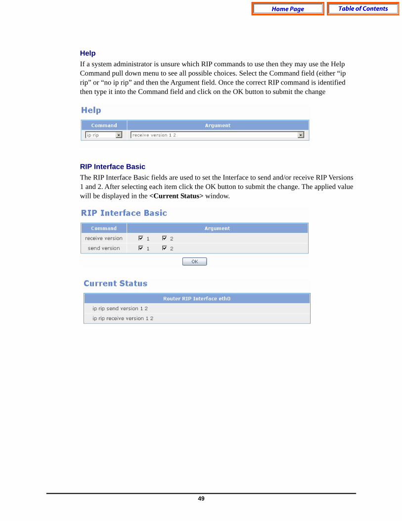
Help If a system administrator is unsure which RIP commands to use then they may use the Help Command pull down menu to see all possible choices. Select the Command field (either “ip rip” or “no ip rip” and then the Argument field. Once the correct RIP command is identified then type it into the Command field and click on the OK button to submit the change
RIP Interface Basic The RIP Interface Basic fields are used to set the Interface to send and/or receive RIP Versions 1 and 2. After selecting each item click the OK button to submit the change. The applied value will be displayed in the <Current Status> window.

50
OSPF The Open Shortest Path First (OSPF) protocol is a link-state, hierarchical routing protocol. Dijkstra's algorithm which is used to calculate the shortest path tree. It uses cost as its routing metric. A link state database is constructed of the network topology which is identical with all routers in the OSPF area. OSPF is perhaps the most widely used Routing Protocol in large networks. Select the [Layer3] [Configuration] [OSPF] submenu to begin configuring OSPF. On the GSIMT/GSIM the OSPF information (basic and advanced commands)can be entered by using the Command field or by using the OSPF Basic fields (basic commands only). In the Command field and OSPF Basic examples listed below the network administrator is setting the 192.168.1.0 network for OSPF with an area of 100. Click the OK button to apply the change.
51
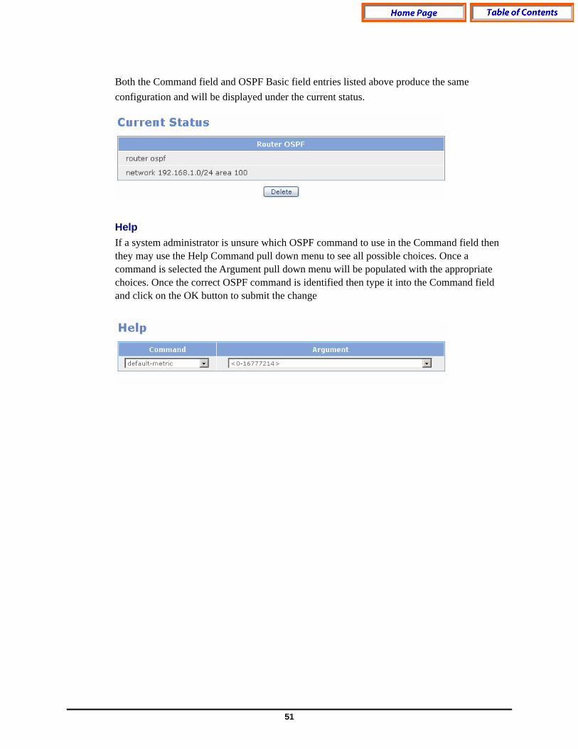
Both the Command field and OSPF Basic field entries listed above produce the same configuration and will be displayed under the current status.
Help If a system administrator is unsure which OSPF command to use in the Command field then they may use the Help Command pull down menu to see all possible choices. Once a command is selected the Argument pull down menu will be populated with the appropriate choices. Once the correct OSPF command is identified then type it into the Command field and click on the OK button to submit the change
52
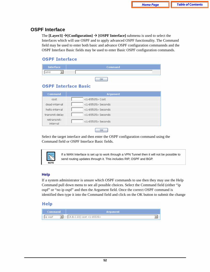
OSPF Interface The [Layer3] [Configuration] [OSPF Interface] submenu is used to select the Interfaces which will use OSPF and to apply advanced OSPF functionality. The Command field may be used to enter both basic and advance OSPF configuration commannds and the OSPF Interface Basic fields may be used to enter Basic OSPF configuration commands. Select the target interface and then enter the OSPF configuration command using the Command field or OSPF Interface Basic fields.
If a WAN Interface is set up to work through a VPN Tunnel then it will not be possible to send routing updates through it. This includes RIP, OSPF and BGP.
Help If a system administrator is unsure which OSPF commands to use then they may use the Help Command pull down menu to see all possible choices. Select the Command field (either “ip ospf” or “no ip ospf” and then the Argument field. Once the correct OSPF command is identified then type it into the Command field and click on the OK button to submit the change
53
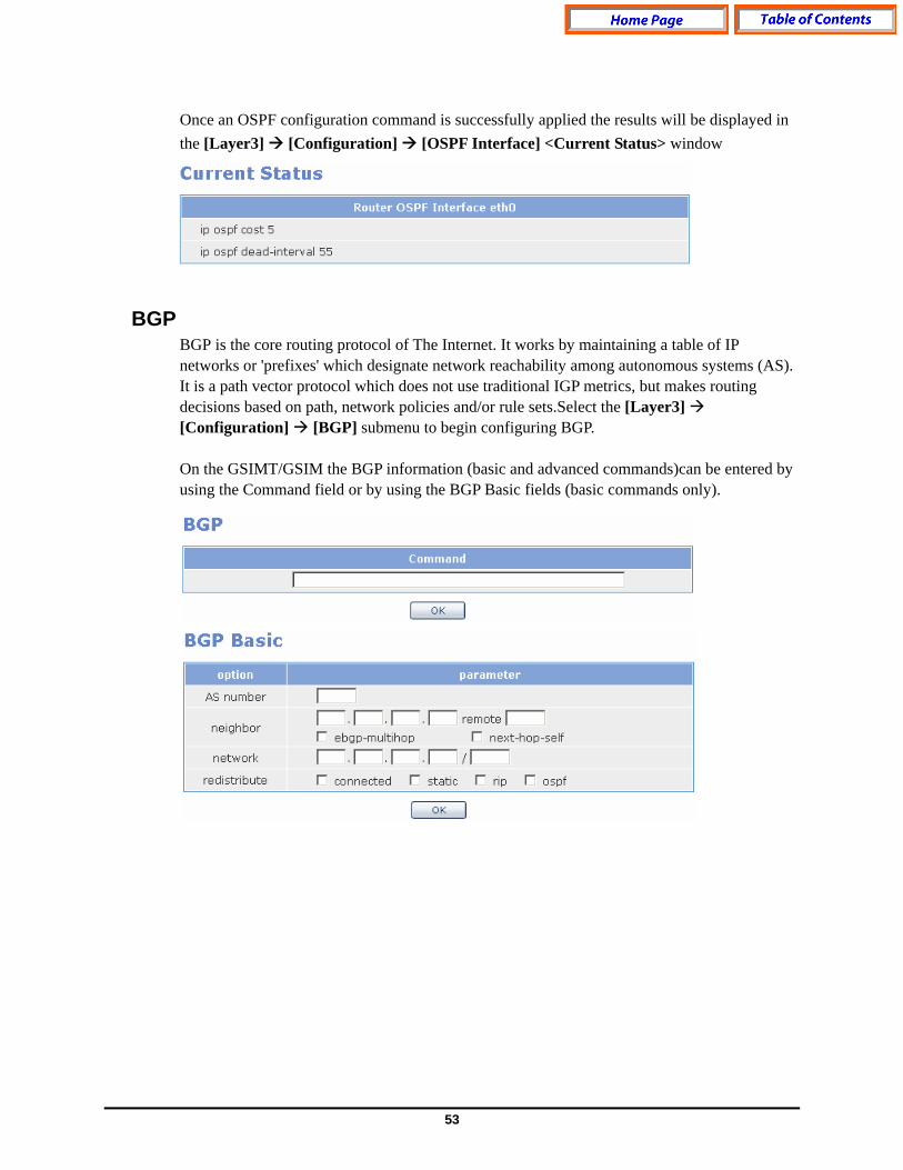
Once an OSPF configuration command is successfully applied the results will be displayed in the [Layer3] [Configuration] [OSPF Interface] <Current Status> window
BGP
BGP is the core routing protocol of The Internet. It works by maintaining a table of IP networks or 'prefixes' which designate network reachability among autonomous systems (AS). It is a path vector protocol which does not use traditional IGP metrics, but makes routing decisions based on path, network policies and/or rule sets.Select the [Layer3] [Configuration] [BGP] submenu to begin configuring BGP. On the GSIMT/GSIM the BGP information (basic and advanced commands)can be entered by using the Command field or by using the BGP Basic fields (basic commands only).
54
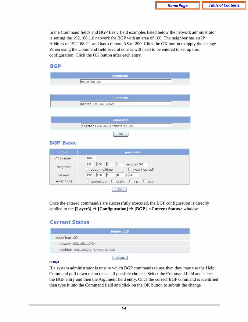
In the Command fields and BGP Basic field examples listed below the network administrator is setting the 192.168.1.0 network for BGP with an area of 100. The neighbor has an IP Address of 192.168.2.1 and has a remote AS of 200. Click the OK button to apply the change. When using the Command field several entries will need to be entered to set up this configuration. Click the OK button after each entry. Once the entered command/s are successfully executed, the BGP configuration is directly applied to the [Layer3] [Configuration] [BGP]. <Current Status> window.
Help If a system administrator is unsure which BGP commands to use then they may use the Help Command pull down menu to see all possible choices. Select the Command field and select the BGP entry and then the Argument field entry. Once the correct BGP command is identified then type it into the Command field and click on the OK button to submit the change
55
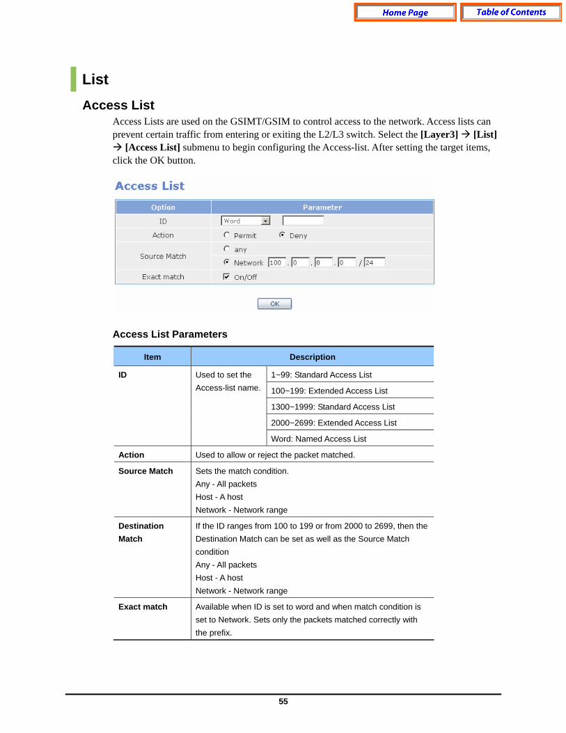
List Access List
Access Lists are used on the GSIMT/GSIM to control access to the network. Access lists can prevent certain traffic from entering or exiting the L2/L3 switch. Select the [Layer3] [List]
[Access List] submenu to begin configuring the Access-list. After setting the target items, click the OK button.
Access List Parameters
Item Description
1~99: Standard Access List
100~199: Extended Access List
1300~1999: Standard Access List
2000~2699: Extended Access List
ID Used to set the Access-list name.
Word: Named Access List
Action Used to allow or reject the packet matched.
Source Match Sets the match condition. Any - All packets Host - A host Network - Network range
Destination Match
If the ID ranges from 100 to 199 or from 2000 to 2699, then the Destination Match can be set as well as the Source Match condition Any - All packets Host - A host Network - Network range
Exact match Available when ID is set to word and when match condition is set to Network. Sets only the packets matched correctly with the prefix.

56
Once the Access List command is successfully executed then the results are directly applied to the [Layer3] [List] [Access List] <Current Status> window. In order to delete an Access List select the radio button to the left of the Access List and then click the Delete button. Current Status Fields
Field Description
ID Access-list name information
Entry Access-list description
Prefix List The Prefix List provides the most powerful prefix based filtering mechanism. In addition to access-list functionality the Prefix List has prefix length range specification and sequential number specification. You can add or delete prefix based filters to arbitrary points of Prefix List using sequential number specification. Select the [Layer3] [List] [Prefix List] submenu to configure the Prefix-list. If no Prefix List is specified on the GSIMT/GSIM then it acts as a permit rule. If the Prefix List is defined, and no match is found, then a default rule of deny is applied.

57
Prefix List Parameters
Parameter Description
ID Used to set the prefix-list name.
Seq Used to set the sequence No. of the prefix-list.
Action Allows/Rejects the packets matched.
Prefix Match Sets the match condition. - Any: All packets - Network: network range. .
Once the Prefix List information is entered and saved then the results are directly applied to the [Layer3] [List] [Prefix List] <Current Status> window. Once a Prefix List is set in the GSIMT/GSIM it can be removed by selecting the radio button of the Prefix List and then click the Delete button. Prefix List Current Status Fields
Field Description
ID Prefix-list name information
Entry Prefix-list information
Route-Map Route maps are similar to access lists as they both have criteria for matching the details of certain packets and an action of permitting or denying those packets. Use the [Layer3] [List] [Route-Map] submenu to begin configuring Route-Map. Enter the target value and then click the OK button to save the change.

58
Route-Map Parameter Description
Parameter Description
Name Route-map name
Action Sets whether to apply set operation.
Sequence Sets the sequence No. to additionally delete a route-map
If the Route-Map command is successfully entered and saved then the results will be directly applied to the <Current Status> of the [Layer3] [List] [Route-Map] submenu. Route-Map Setting Field Description
Field Description
Name Route-map name
Entry Route-map information
Once a Route-Map is created it can be defined. Highlight the radio button to the left of the Route –Map and click the edit button.
59
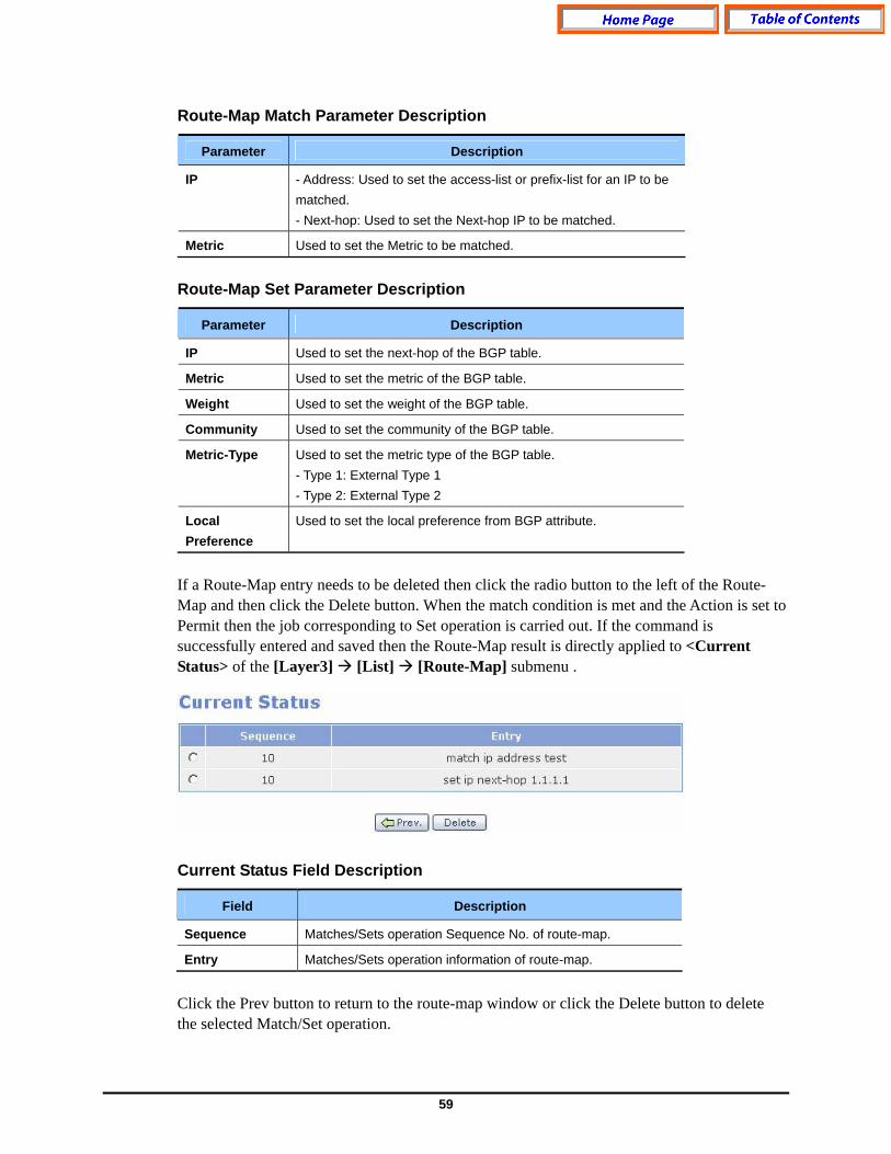
Route-Map Match Parameter Description
Parameter Description
IP - Address: Used to set the access-list or prefix-list for an IP to be matched. - Next-hop: Used to set the Next-hop IP to be matched.
Metric Used to set the Metric to be matched.
Route-Map Set Parameter Description
Parameter Description
IP Used to set the next-hop of the BGP table.
Metric Used to set the metric of the BGP table.
Weight Used to set the weight of the BGP table.
Community Used to set the community of the BGP table.
Metric-Type Used to set the metric type of the BGP table. - Type 1: External Type 1 - Type 2: External Type 2
Local Preference
Used to set the local preference from BGP attribute.
If a Route-Map entry needs to be deleted then click the radio button to the left of the Route-Map and then click the Delete button. When the match condition is met and the Action is set to Permit then the job corresponding to Set operation is carried out. If the command is successfully entered and saved then the Route-Map result is directly applied to <Current Status> of the [Layer3] [List] [Route-Map] submenu . Current Status Field Description
Field Description
Sequence Matches/Sets operation Sequence No. of route-map.
Entry Matches/Sets operation information of route-map.
Click the Prev button to return to the route-map window or click the Delete button to delete the selected Match/Set operation.
60
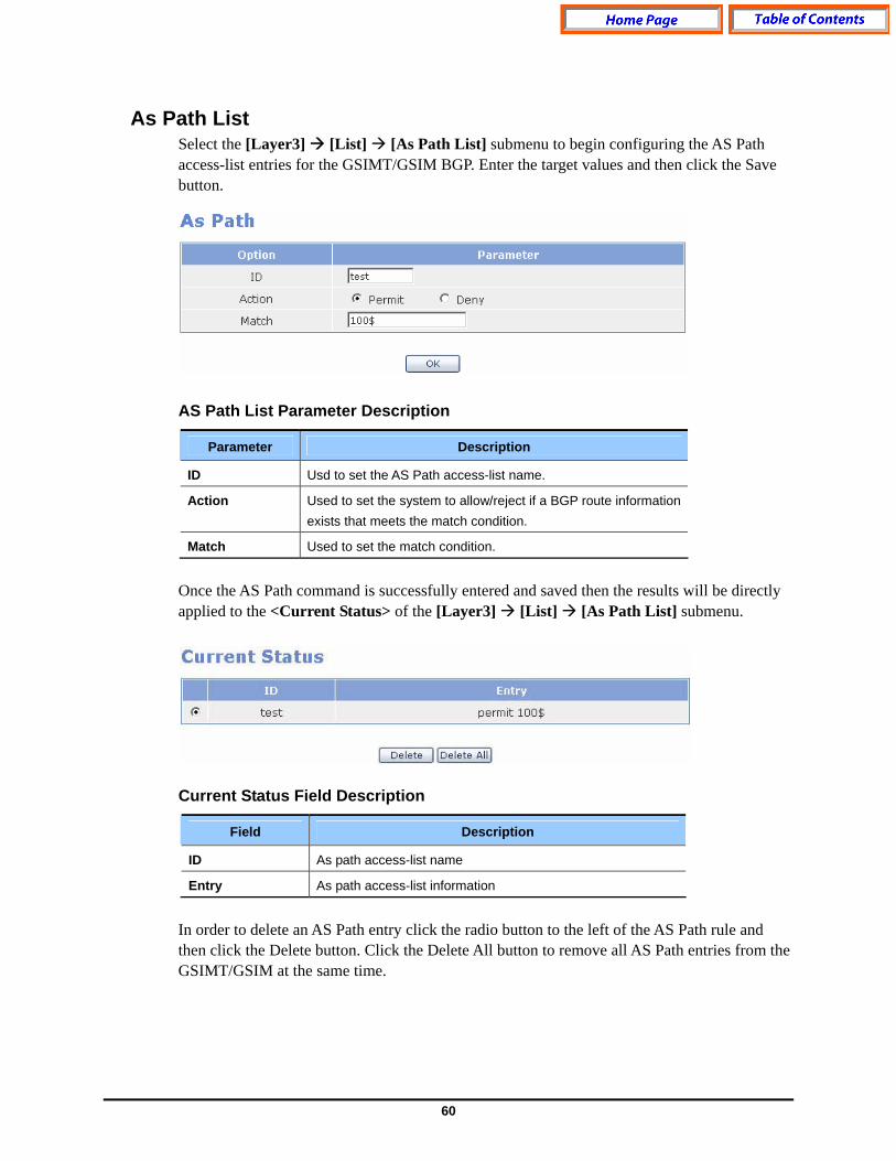
As Path List Select the [Layer3] [List] [As Path List] submenu to begin configuring the AS Path access-list entries for the GSIMT/GSIM BGP. Enter the target values and then click the Save button. AS Path List Parameter Description
Parameter Description
ID Usd to set the AS Path access-list name.
Action Used to set the system to allow/reject if a BGP route information exists that meets the match condition.
Match Used to set the match condition.
Once the AS Path command is successfully entered and saved then the results will be directly applied to the <Current Status> of the [Layer3] [List] [As Path List] submenu.
Current Status Field Description
Field Description
ID As path access-list name
Entry As path access-list information
In order to delete an AS Path entry click the radio button to the left of the AS Path rule and then click the Delete button. Click the Delete All button to remove all AS Path entries from the GSIMT/GSIM at the same time.
61
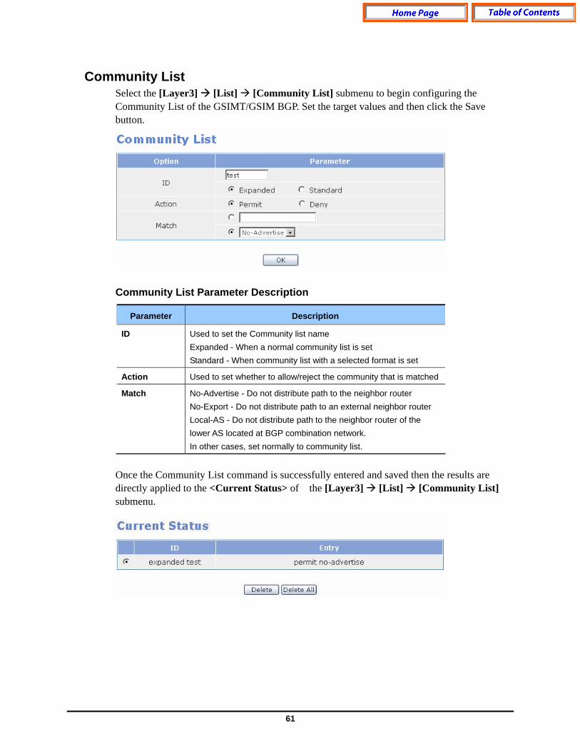
Community List Select the [Layer3] [List] [Community List] submenu to begin configuring the Community List of the GSIMT/GSIM BGP. Set the target values and then click the Save button. Community List Parameter Description
Parameter Description
ID Used to set the Community list name Expanded - When a normal community list is set Standard - When community list with a selected format is set
Action Used to set whether to allow/reject the community that is matched
Match No-Advertise - Do not distribute path to the neighbor router No-Export - Do not distribute path to an external neighbor router Local-AS - Do not distribute path to the neighbor router of the lower AS located at BGP combination network. In other cases, set normally to community list.
Once the Community List command is successfully entered and saved then the results are directly applied to the <Current Status> of the [Layer3] [List] [Community List] submenu.

62
Current Status Field Description
Field Description
ID Community list name
Entry Community list information
In order to remove a Community List entry click the radio button to the left of the Community List rule and then click the Delete button. Click the Delete All button to remove all community-list entries at the same time.
Key Chain The GSIMT/GSIM uses the Key Chain window for setting up MD5 Authentication for (RIP) Version 2 packets. Select the [Layer3] [List] [Key Chain] submenu to begin configuring the Key Chain information. Enter the values and then click the OK button. Key Chain Parameter Description
Parameter Description
Key Chain Name Used to name the Key Chain rule
Key ID ID number of the Key
Key String Password to be used in authentication process
Once the Key Chain command is successfully entered and saved then the results are directly applied to the <Current Status> of the [Layer3] [List] [Key Chain] submenu.

63
In order to remove a Key Chain entry click the radio button to the left of the Key Chain rule and then click the Delete button. Click the Delete All button to remove all Key Chain entries at the same time.
Status RIP
The [Layer3] [Status] [RIP] submenu is used to display the RIP connection status and information of the GSIMT/GSIM.
RIP Status Field Descrition
Field Description
Network Displays the network information
Next Hop Next Hop address of the RIP route that sends neighbor.
Metric Metric information.
From Displays the address being connected.
If Displays the interface information.
Time Update time.
64
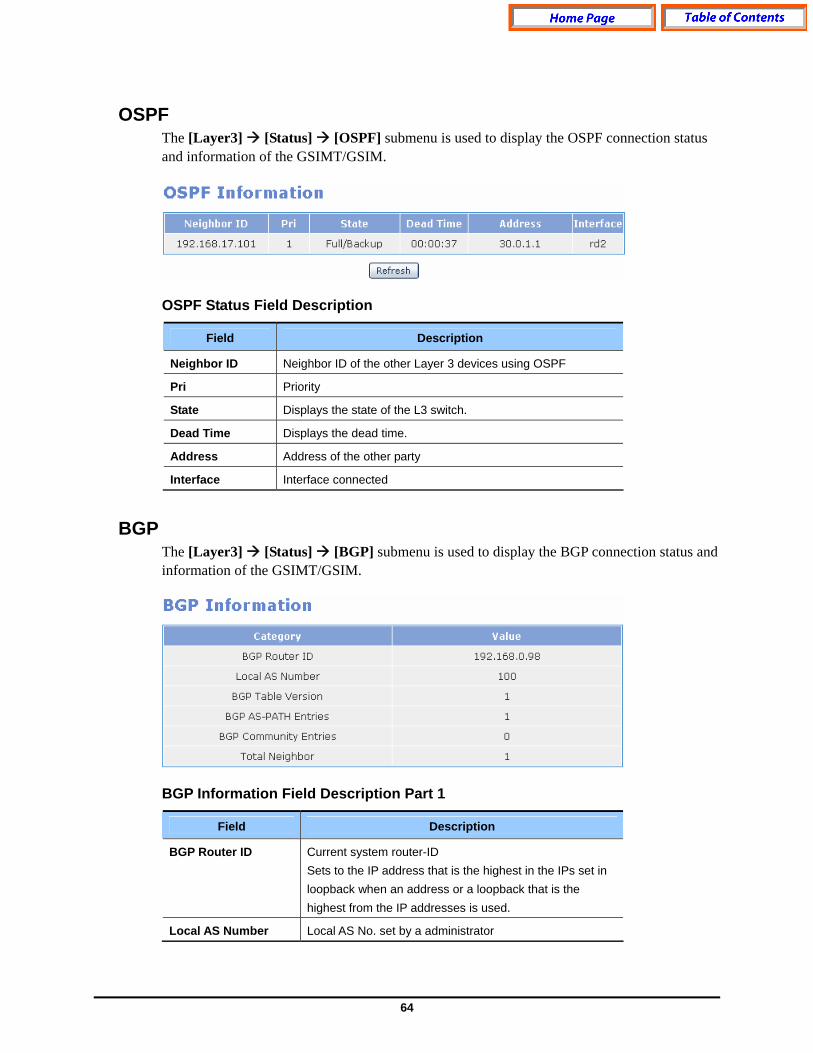
OSPF The [Layer3] [Status] [OSPF] submenu is used to display the OSPF connection status and information of the GSIMT/GSIM. OSPF Status Field Description
Field Description
Neighbor ID Neighbor ID of the other Layer 3 devices using OSPF
Pri Priority
State Displays the state of the L3 switch.
Dead Time Displays the dead time.
Address Address of the other party
Interface Interface connected
BGP The [Layer3] [Status] [BGP] submenu is used to display the BGP connection status and information of the GSIMT/GSIM. BGP Information Field Description Part 1
Field Description
BGP Router ID Current system router-ID Sets to the IP address that is the highest in the IPs set in loopback when an address or a loopback that is the highest from the IP addresses is used.
Local AS Number Local AS No. set by a administrator

65
Field Description
BGP Table Version BGP table change version information
BGP AS-PATH Entries Number of AS PATH Hash tables used in BGP
BGP Community Entries
Number of Hash table of community attribute used in BGP
Total Neighbor Total sum of BGP neighbor
BGP Information Field Description Part 2
Field Description
Neighbor IP address of the neighbor router or L2/L3 switch
V Version No. used by neighbor
AS AS No. of neighbor
MsgRcvd Message number received from neighbor
MsgSent Message number sent from neighbor
TblVer Latest BGP database version sent from neighbor
InQ Number of messages that should be received from neighbor and processed
OutQ Number of messages sent to neighbor
Up/Down Displays the path time when BGP session is finished. Displays the status when BGP session is not finished.
State/PfxRcd Number of BGP routes via neighbor or peer group or BGP current status
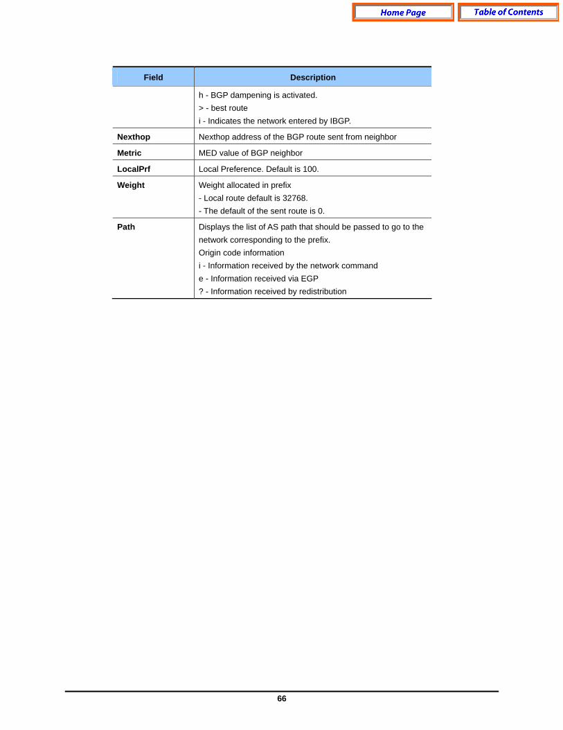
BGP Information Field Description Part 3
Field Description
Network Displays network information. Status code information s - Indicates the suppressed network. * - Indicates proper network information.
66
Field Description
h - BGP dampening is activated. > - best route i - Indicates the network entered by IBGP.
Nexthop Nexthop address of the BGP route sent from neighbor
Metric MED value of BGP neighbor
LocalPrf Local Preference. Default is 100.
Weight Weight allocated in prefix - Local route default is 32768. - The default of the sent route is 0.
Path Displays the list of AS path that should be passed to go to the network corresponding to the prefix. Origin code information i - Information received by the network command e - Information received via EGP ? - Information received by redistribution

67
IPMC For large amounts of data, IP Multicast is more efficient than normal Internet transmissions because the same data is broadcast to many recipients simultaneously. Unlike traditional Internet traffic that requires separate connections for each source-destination pair, IP Multicasting allows many recipients to share the same source. This means that just one set of packets is transmitted for all the destinations. Select the [IPMC] menu to begin configuring IPMC. The submenus will be displayed in the upper left side of the window as follows: IPMC Menu Description
Menu Submenu Description
Mroutes Displays the Multicast Routing Entry. General
Management Used to starts/stop IPMC protocol daemons.
IGMP Used to display or change the IGMP configuration.
DVMRP Used to display or change the DVMRP default configuration.
DVMRP Intf Used to display or change the VIF of theDVMRP.
PIM-SM Used to display or change the PIM-SM default configuration.
Configuration
PIM-SM Intf Used to display or change the VIF PIM-SM.
IGMP Groups Used to displays the IGMP Group information.
DVMRP Used to display the DVMRP neighbor and Prune information.
Status
PIM-SM Used to display the PIM-SM Neighbor information.
68
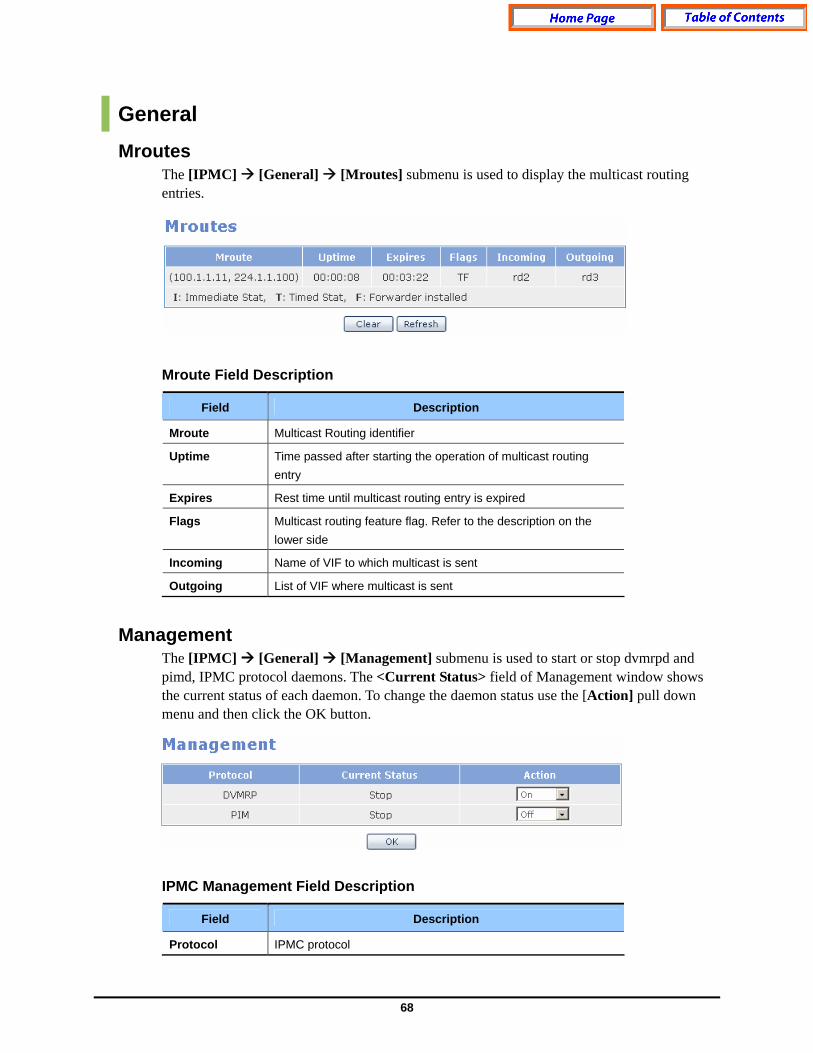
General Mroutes
The [IPMC] [General] [Mroutes] submenu is used to display the multicast routing entries. Mroute Field Description
Field Description
Mroute Multicast Routing identifier
Uptime Time passed after starting the operation of multicast routing entry
Expires Rest time until multicast routing entry is expired
Flags Multicast routing feature flag. Refer to the description on the lower side
Incoming Name of VIF to which multicast is sent
Outgoing List of VIF where multicast is sent
Management The [IPMC] [General] [Management] submenu is used to start or stop dvmrpd and pimd, IPMC protocol daemons. The <Current Status> field of Management window shows the current status of each daemon. To change the daemon status use the [Action] pull down menu and then click the OK button. IPMC Management Field Description
Field Description
Protocol IPMC protocol

69
Field Description
Current Status Current IPMC protocol demon status
Action New status of IPMC protocol demon status
Configuration IGMP
The Internet Group Management Protocol is a communications protocol used to manage the membership of Internet Protocol multicast groups. IGMP is used by IP hosts and adjacent multicast routers to establish multicast group memberships. The [IPMC] [Configuration] submenu is used to display and change the GSIMT/GSIM IGMP configuration.
IGMP & Help IGMP commands can be entered into the Command field and saved by clicking the OK button.. Use the Help field to find an IGMP command.
IGMP Basic Enter the new IGMP information and then click the OK button to change the default configuration of IGMP.

70
IGMP Basic Parameter Description
Parameter Description
Interface Select the target IGMP interface and select All. Then, all interface configuration values are applied
IGMP Query Interval
Cycle of sending IGMP Membership Query
Max Response Time
Maximum time of waiting a response after sending Membership Query
IGMP Interface Information This section of the [IPMC] [Configuration] [IGMP] window is used to display the IGMP interfaces. IGMP Interface Field Description
Field Description
Address IGMP group address
Intf IGMP interface name
Querier Address
IP address of IGMP interface that sends membership query. IP address of Designate Router(DR)
Query Interval Cycle of sending Membership Query
Max Resp Time Maximum time of waiting a response to Membership Query
71
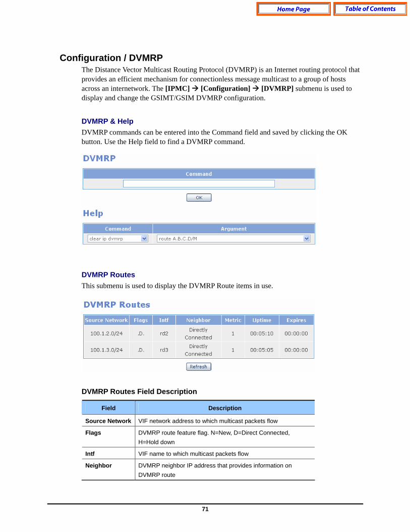
Configuration / DVMRP The Distance Vector Multicast Routing Protocol (DVMRP) is an Internet routing protocol that provides an efficient mechanism for connectionless message multicast to a group of hosts across an internetwork. The [IPMC] [Configuration] [DVMRP] submenu is used to display and change the GSIMT/GSIM DVMRP configuration.
DVMRP & Help DVMRP commands can be entered into the Command field and saved by clicking the OK button. Use the Help field to find a DVMRP command.
DVMRP Routes This submenu is used to display the DVMRP Route items in use. DVMRP Routes Field Description
Field Description
Source Network VIF network address to which multicast packets flow
Flags DVMRP route feature flag. N=New, D=Direct Connected, H=Hold down
Intf VIF name to which multicast packets flow
Neighbor DVMRP neighbor IP address that provides information on DVMRP route
72
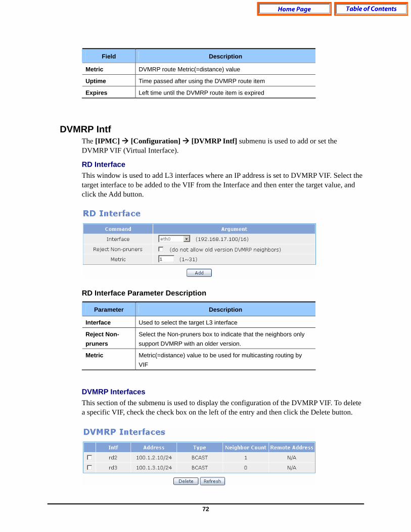
Field Description
Metric DVMRP route Metric(=distance) value
Uptime Time passed after using the DVMRP route item
Expires Left time until the DVMRP route item is expired
DVMRP Intf The [IPMC] [Configuration] [DVMRP Intf] submenu is used to add or set the DVMRP VIF (Virtual Interface).
RD Interface This window is used to add L3 interfaces where an IP address is set to DVMRP VIF. Select the target interface to be added to the VIF from the Interface and then enter the target value, and click the Add button. RD Interface Parameter Description
Parameter Description
Interface Used to select the target L3 interface
Reject Non-pruners
Select the Non-pruners box to indicate that the neighbors only support DVMRP with an older version.
Metric Metric(=distance) value to be used for multicasting routing by VIF
DVMRP Interfaces This section of the submenu is used to display the configuration of the DVMRP VIF. To delete a specific VIF, check the check box on the left of the entry and then click the Delete button.

73
DVMRP Interfaces Field Description
Field Description
Intf DVMRP VIF name
Address IP address of DVMRP VIF
Type DVMRP VIF type. Tunnel, Point-to-Point, Broadcast
Neighbor Count Number of neighbors connected to DVMRP VIF
Remote Address
Address of the other party in case of Tunnel or Point-to-Point type.(Peer Address)
PIM-SM PIM-SM or Protocol Independent Multicast - Sparse-Mode (PIM-SM) is a protocol for efficiently routing to multicast groups that may span wide-area (and inter-domain) internets. Use the [IPMC] [Configuration] [PIM-SM] submenu to begin configuring the PIM-SM on the GSIMT/GSIM.
PIM-SM & Help PIM-SM commands can be entered into the Command field and saved by clicking the OK button. Use the Help field to find a PIM-SM command.
74
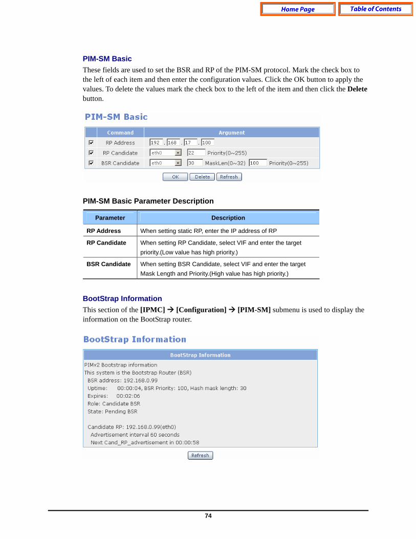
PIM-SM Basic These fields are used to set the BSR and RP of the PIM-SM protocol. Mark the check box to the left of each item and then enter the configuration values. Click the OK button to apply the values. To delete the values mark the check box to the left of the item and then click the Delete button. PIM-SM Basic Parameter Description
Parameter Description
RP Address When setting static RP, enter the IP address of RP
RP Candidate When setting RP Candidate, select VIF and enter the target priority.(Low value has high priority.)
BSR Candidate When setting BSR Candidate, select VIF and enter the target Mask Length and Priority.(High value has high priority.)
BootStrap Information This section of the [IPMC] [Configuration] [PIM-SM] submenu is used to display the information on the BootStrap router.
75
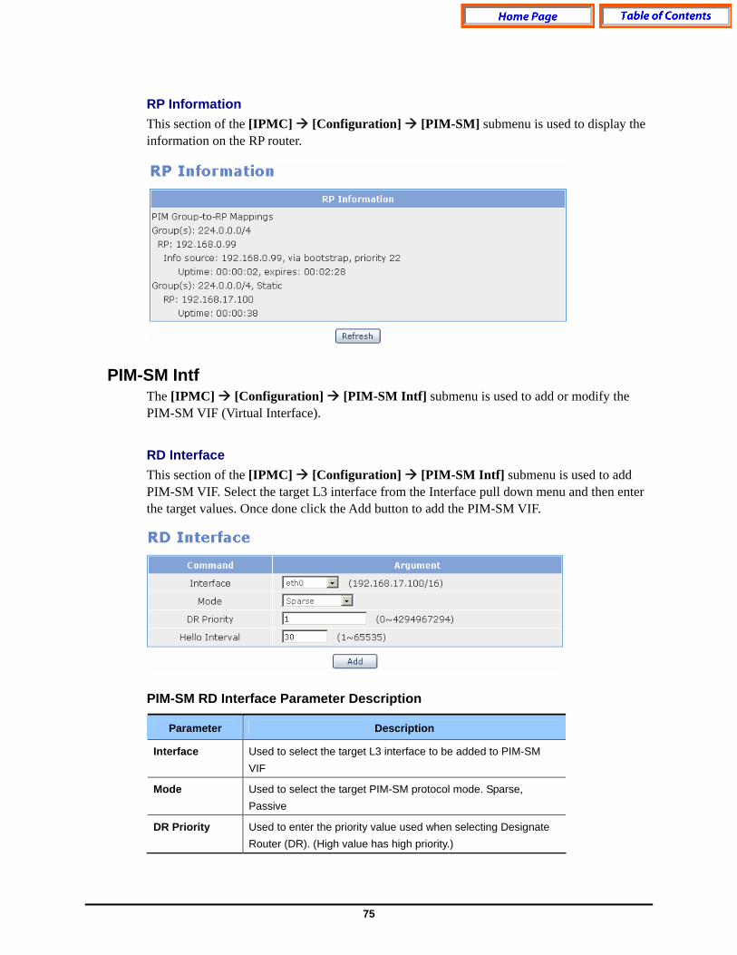
RP Information This section of the [IPMC] [Configuration] [PIM-SM] submenu is used to display the information on the RP router.
PIM-SM Intf
The [IPMC] [Configuration] [PIM-SM Intf] submenu is used to add or modify the PIM-SM VIF (Virtual Interface).
RD Interface This section of the [IPMC] [Configuration] [PIM-SM Intf] submenu is used to add PIM-SM VIF. Select the target L3 interface from the Interface pull down menu and then enter the target values. Once done click the Add button to add the PIM-SM VIF. PIM-SM RD Interface Parameter Description
Parameter Description
Interface Used to select the target L3 interface to be added to PIM-SM VIF
Mode Used to select the target PIM-SM protocol mode. Sparse, Passive
DR Priority Used to enter the priority value used when selecting Designate Router (DR). (High value has high priority.)

76
Parameter Description
Hello Interval Cycle of exchanging hello packets with connected PIM-SM neighbors
PIM-SM Interfaces This section of the [IPMC] [Configuration] [PIM-SM Intf] submenu is used to display the VIFs added to the PIM-SM. To delete a VIF, click the check box on the left of the entry and then click the Delete button.
IGMP Groups The [IPMC] [Status] [IGMP Groups] submenu is used to display the information on registered IGMP groups. IGMP Groups Field Description
Field Description
Group Address IGMP group address
Intf IGMP interface name
Uptime Time passed after IGMP group is created
Expires Left time until the IGMP Group information is expired
Last Reporter Client IP address that sends the last membership report
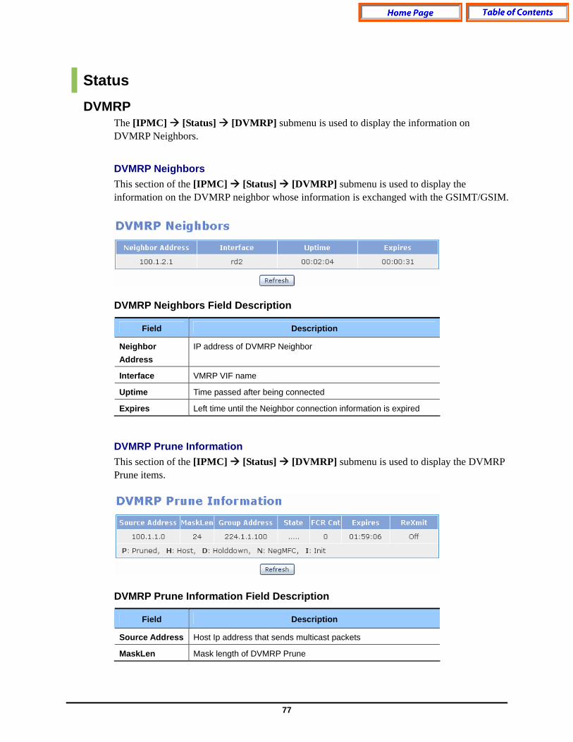
77
Status DVMRP
The [IPMC] [Status] [DVMRP] submenu is used to display the information on DVMRP Neighbors.
DVMRP Neighbors This section of the [IPMC] [Status] [DVMRP] submenu is used to display the information on the DVMRP neighbor whose information is exchanged with the GSIMT/GSIM. DVMRP Neighbors Field Description
Field Description
Neighbor Address
IP address of DVMRP Neighbor
Interface VMRP VIF name
Uptime Time passed after being connected
Expires Left time until the Neighbor connection information is expired
DVMRP Prune Information This section of the [IPMC] [Status] [DVMRP] submenu is used to display the DVMRP Prune items. DVMRP Prune Information Field Description
Field Description
Source Address Host Ip address that sends multicast packets
MaskLen Mask length of DVMRP Prune
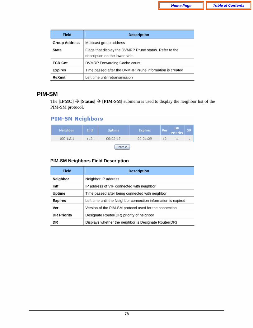
78
Field Description
Group Address Multicast group address
State Flags that display the DVMRP Prune status. Refer to the description on the lower side
FCR Cnt DVMRP Forwarding Cache count
Expires Time passed after the DVMRP Prune information is created
ReXmit Left time until retransmission
PIM-SM The [IPMC] [Status] [PIM-SM] submenu is used to display the neighbor list of the PIM-SM protocol. PIM-SM Neighbors Field Description
Field Description
Neighbor Neighbor IP address
Intf IP address of VIF connected with neighbor
Uptime Time passed after being connected with neighbor
Expires Left time until the Neighbor connection information is expired
Ver Version of the PIM-SM protocol used for the connection
DR Priority Designate Router(DR) priority of neighbor
DR Displays whether the neighbor is Designate Router(DR)
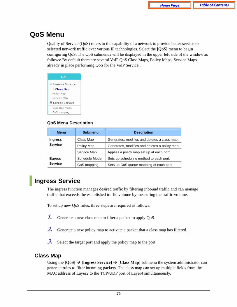
79
QoS Menu Quality of Service (QoS) refers to the capability of a network to provide better service to selected network traffic over various IP technologies. Select the [QoS] menu to begin configuring QoS. The QoS submenus will be displayed in the upper left side of the window as follows: By default there are several VoIP QoS Class Maps, Policy Maps, Service Maps already in place performing QoS for the VoIP Service..
QoS Menu Description
Menu Submenu Description
Class Map Generates, modifies and deletes a class map.
Policy Map Generates, modifies and deletes a policy map.
Ingress Service
Service Map Applies a policy map set up at each port.
Schedule Mode Sets up scheduling method to each port. Egress Service CoS mapping Sets up CoS queue mapping of each port.
Ingress Service The ingress function manages desired traffic by filtering inbound traffic and can manage traffic that exceeds the established traffic volume by measuring the traffic volume. To set up new QoS rules, three steps are required as follows: 1. Generate a new class map to filter a packet to apply QoS. 2. Generate a new policy map to activate a packet that a class map has filtered. 3. Select the target port and apply the policy map to the port.
Class Map Using the [QoS] [Ingress Service] [Class Map] submenu the system administrator can generate rules to filter incoming packets. The class map can set up multiple fields from the MAC address of Layer2 to the TCP/UDP port of Layer4 simultaneously.
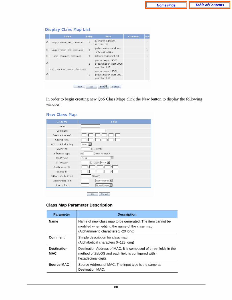
80
In order to begin creating new QoS Class Maps click the New button to display the following window. Class Map Parameter Description
Parameter Description
Name Name of new class map to be generated. The item cannot be modified when editing the name of the class map. (Alphanumeric characters 1~20 long)
Comment Simple description for class map. (Alphabetical characters 0~128 long)
Destination MAC
Destination Address of MAC. It is composed of three fields in the method of ZebOS and each field is configured with 4 hexadecimal digits.
Source MAC Source Address of MAC. The input type is the same as Destination MAC.

81
Parameter Description
802.1p Priority Tag
802.1p Priority Tag(0~7 values)
VLAN Tag VLAN tag(1~4094 )
Ethernet Type Hexadecimal value(2-byte)
ICMP Type (0~18)
IP Protocol (0~255)
Destination IP Configured with four fields and prefixes. (Four fields between 0~255, Prefix between 0~32)
Source IP Same as the destination IP.
Diffserv Code Point
(0~63)
Destination Port
Values between 0~65534 or 1~65536. It is in the form of a multiple of 2 when having a range value
Source Port Same as the destination port.
The following example show a Class Map that filters the priority value of 3 for the source MAC 00:00:00:00:00:01 and 802.1p. Press the OK button to save the class1 Class Map.
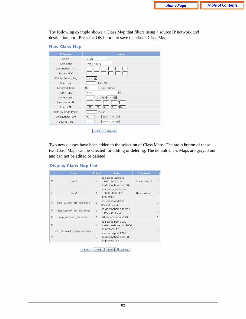
82
The following example shows a Class Map that filters using a source IP network and destination port. Press the OK button to save the class2 Class Map. Two new classes have been added to the selection of Class Maps. The radio button of these two Class Maps can be selected for editing or deleting. The default Class Maps are grayed out and can not be edited or deleted.
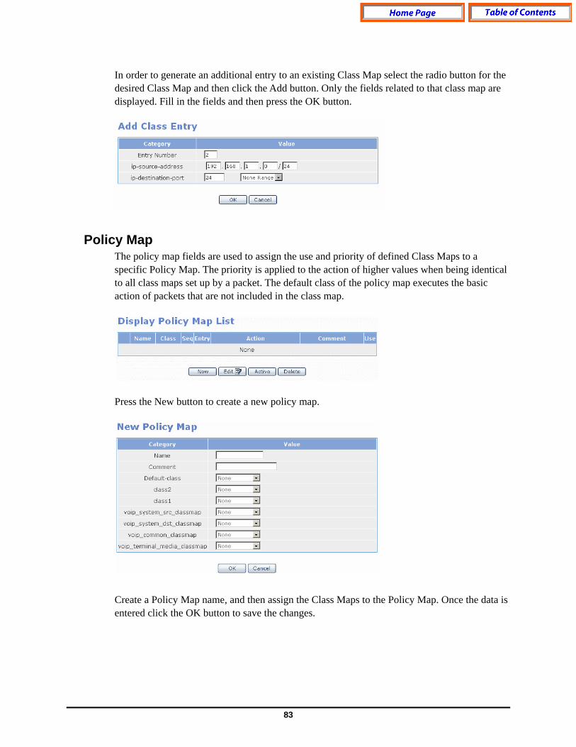
83
In order to generate an additional entry to an existing Class Map select the radio button for the desired Class Map and then click the Add button. Only the fields related to that class map are displayed. Fill in the fields and then press the OK button.
Policy Map The policy map fields are used to assign the use and priority of defined Class Maps to a specific Policy Map. The priority is applied to the action of higher values when being identical to all class maps set up by a packet. The default class of the policy map executes the basic action of packets that are not included in the class map. Press the New button to create a new policy map. Create a Policy Map name, and then assign the Class Maps to the Policy Map. Once the data is entered click the OK button to save the changes.
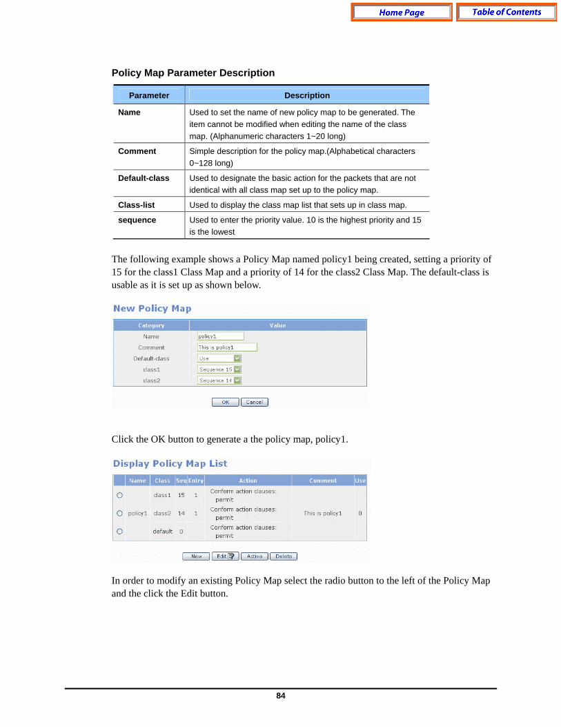
84
Policy Map Parameter Description
Parameter Description
Name Used to set the name of new policy map to be generated. The item cannot be modified when editing the name of the class map. (Alphanumeric characters 1~20 long)
Comment Simple description for the policy map.(Alphabetical characters 0~128 long)
Default-class Used to designate the basic action for the packets that are not identical with all class map set up to the policy map.
Class-list Used to display the class map list that sets up in class map.
sequence Used to enter the priority value. 10 is the highest priority and 15 is the lowest
The following example shows a Policy Map named policy1 being created, setting a priority of 15 for the class1 Class Map and a priority of 14 for the class2 Class Map. The default-class is usable as it is set up as shown below. Click the OK button to generate a the policy map, policy1. In order to modify an existing Policy Map select the radio button to the left of the Policy Map and the click the Edit button.

85
To further define the Policy Map select the radio button to the left of the Policy Map and then click the Active button. The Conform Action fields are where policy actions are set for a particular Policy Map. Conform Action Parameter Description
Parameter Description
permit Switches a packet.
deny Drops a packet without switching.
copy-to-mirror Copies a packet to the port when a mirror port is set up.
increase-counter Increases internal counter.
tos-to-priority Sets up the value of ToS precedence 3bit of the IP header to the value of 802.1p.
priority-to-tos Sets up the value of 802.1p to the value of ToS precedence 3bit of the report IP header.
drop-precedence The packets that the action is set up are drops preferentially when congestion occurs in an egress.
set-out-port-ucast Redirects a unicasted packet to an established port.
set-out-port-non-ucast Redirects a packet that is not an unicast to an established port.
set-out-port-all Re direct to an established port for all packets.
insert-vlanid Changes the value of VLAN ID to the established value.
insert-priority Changes the value of 802.1p to the established value.
set-priority Sets up the priority of packets internally.
insert-tos Changes the value of ToS to the established value.
insert-dscp Changes the value of DSCP to the established value.

86
Parameter Description
set-ecn Changes the value of ECN to the established value.
The Exceed Action fields are where the administrator sets up the action for packets exceeding the established rate-limit bandwidth. Exceed Action Parameter Description
Parameter Description
rate-limit
- limit: The value of a bandwidth to apply exceed-action. - burst: The value of burst to apply exceed-action.
permit Switches a packet.
deny Drops a packet without switching.
drop- precedence
A packet that an action is set up is dropped preferentially when congestion occurs.
insert-dscp Changes the value of DSCP to the established value.
set-ecn Changes the value of ECN to the established value.

87
The Conform Action or Exceed Action functions performs multiple actions and ‘permit’ and ‘deny’ is set up exclusively. In the following example, Conform Action is set up as traffic exceeding 500Mbps are denied when the value of dscp is 3 for the packets included in the class1 and the internal priority is 7. After configuring the Confirm and Exceed Action parameters the window is displayed as follows:
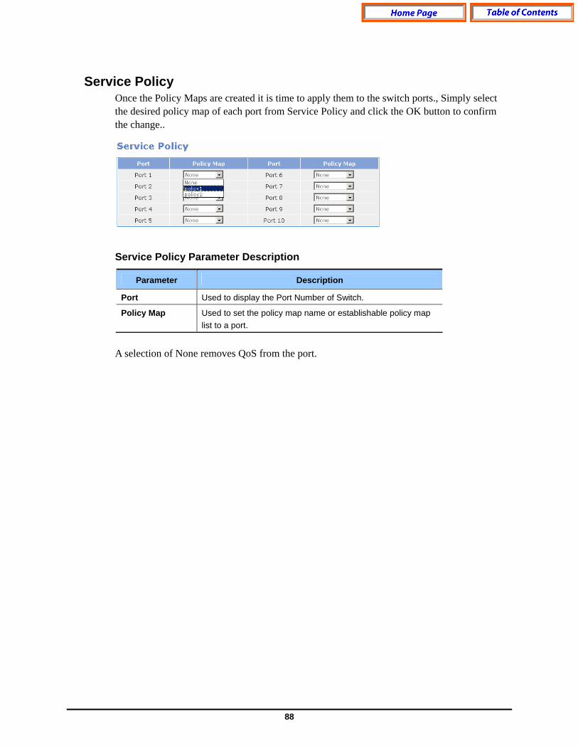
88
Service Policy Once the Policy Maps are created it is time to apply them to the switch ports., Simply select the desired policy map of each port from Service Policy and click the OK button to confirm the change.. Service Policy Parameter Description
Parameter Description
Port Used to display the Port Number of Switch.
Policy Map Used to set the policy map name or establishable policy map list to a port.
A selection of None removes QoS from the port.
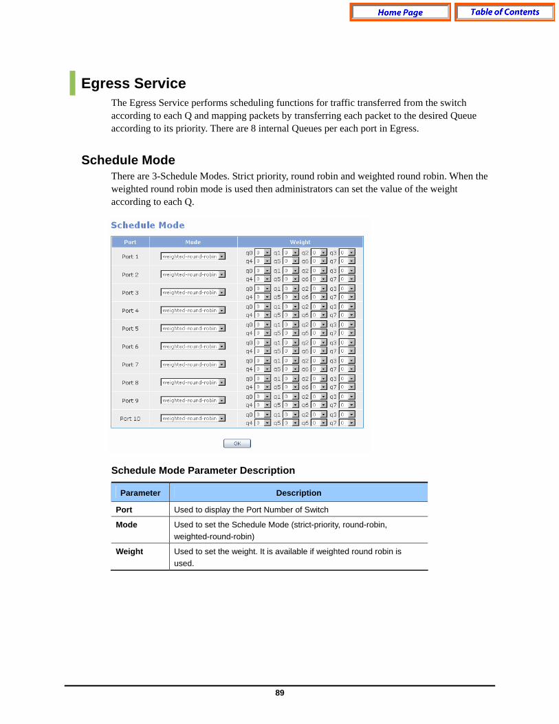
89
Egress Service The Egress Service performs scheduling functions for traffic transferred from the switch according to each Q and mapping packets by transferring each packet to the desired Queue according to its priority. There are 8 internal Queues per each port in Egress.
Schedule Mode There are 3-Schedule Modes. Strict priority, round robin and weighted round robin. When the weighted round robin mode is used then administrators can set the value of the weight according to each Q. Schedule Mode Parameter Description
Parameter Description
Port Used to display the Port Number of Switch
Mode Used to set the Schedule Mode (strict-priority, round-robin, weighted-round-robin)
Weight Used to set the weight. It is available if weighted round robin is used.

90
CoS Mapping Packets are transferred to each Q according to the priority (0~7). Basically, the priority 0 is mapped to Q 0 and the priority 7 is mapped to Q 7 sequentially. The following shows a window that the packet of Priority 3 is changed to Q 4 instead of Q 3 in Port3. Each Q has its own threshold. If a value that is higher than the threshold is led into the Q, the value is dropped. CoS Mapping Parameter Description
Parameter Description
Port Used to set the Port Number of Switch
Priority Priority Value (0~7) of packet
Queue Q (0~7) to serve packet
Threshold Used to set the Threshold (0~2048) to set up each Q (0~2048)
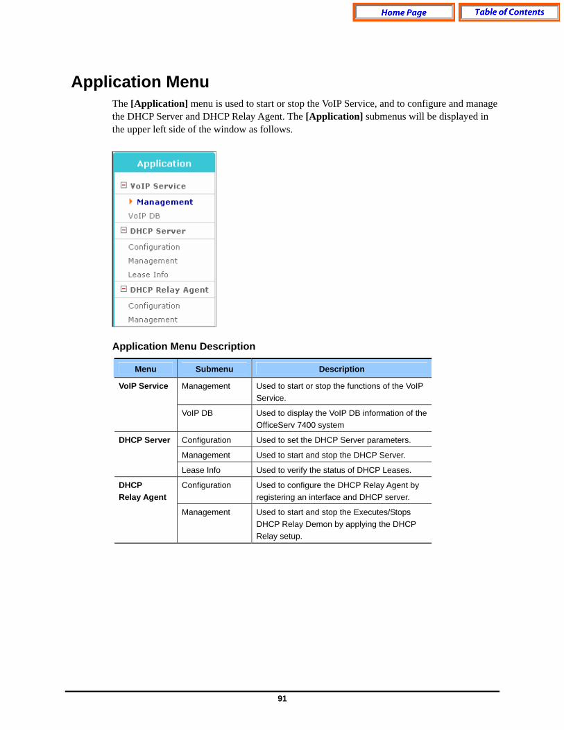
91
Application Menu The [Application] menu is used to start or stop the VoIP Service, and to configure and manage the DHCP Server and DHCP Relay Agent. The [Application] submenus will be displayed in the upper left side of the window as follows.
Application Menu Description
Menu Submenu Description
Management Used to start or stop the functions of the VoIP Service.
VoIP Service
VoIP DB Used to display the VoIP DB information of the OfficeServ 7400 system
Configuration Used to set the DHCP Server parameters.
Management Used to start and stop the DHCP Server.
DHCP Server
Lease Info Used to verify the status of DHCP Leases.
Configuration Used to configure the DHCP Relay Agent by registering an interface and DHCP server.
DHCP Relay Agent
Management Used to start and stop the Executes/Stops DHCP Relay Demon by applying the DHCP Relay setup.

92
VoIP Service Menu Select the [Application] [VoIP Service] submenu to start and stop the VoIP Service and the view the the VoIP DB.
Management Using the [Application] [VoIP Service] [Management] submenu the system administrator can start or stop the VoIP Service. By default the VoIP Service is running after the GSIMT/GSIM finishes its booting cycle. Click the Stop or Run button to change the status of VoIP Service.
VoIP Management Parameter Description
Parameter Description
Activity Used to display the status of the current VoIP Service.
Action Used to change the status of VoIP Service. .
VoIP DB Using the [Application] [VoIP Status] [VoIP DB] submenu the system administrator can display the current VoIP Service information on the OfficeServ 7400 system.
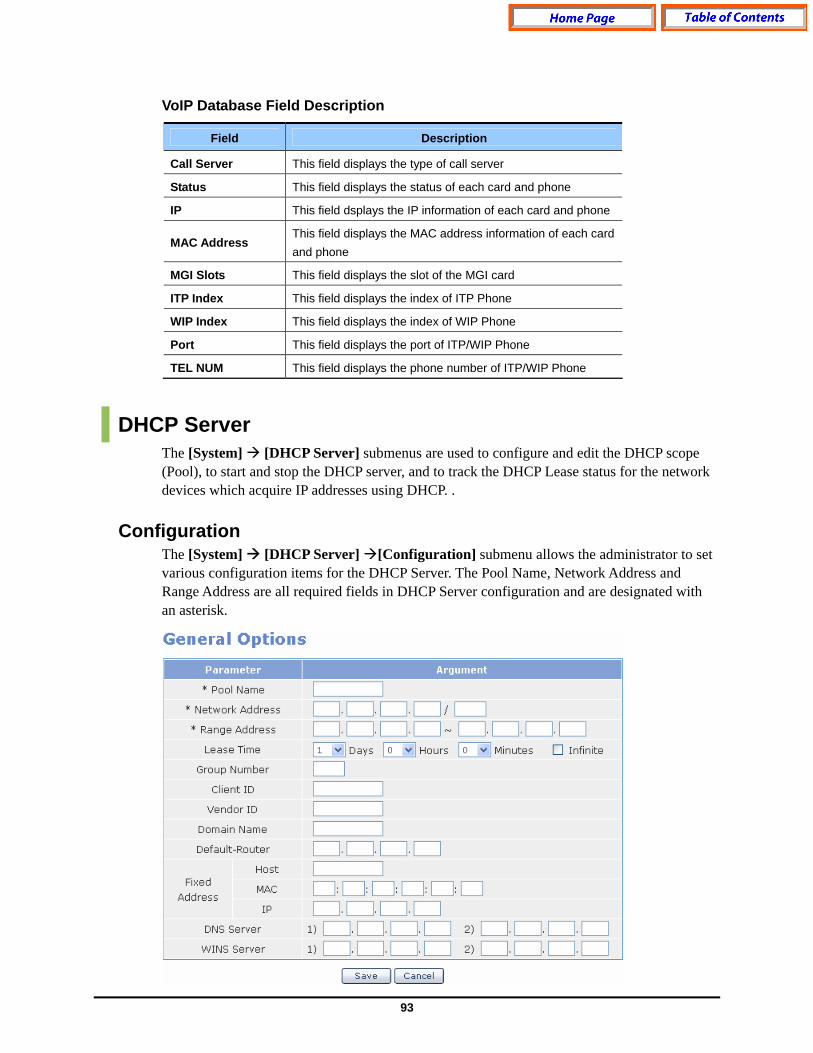
93
VoIP Database Field Description
Field Description
Call Server This field displays the type of call server
Status This field displays the status of each card and phone
IP This field dsplays the IP information of each card and phone
MAC Address This field displays the MAC address information of each card and phone
MGI Slots This field displays the slot of the MGI card
ITP Index This field displays the index of ITP Phone
WIP Index This field displays the index of WIP Phone
Port This field displays the port of ITP/WIP Phone
TEL NUM This field displays the phone number of ITP/WIP Phone
DHCP Server The [System] [DHCP Server] submenus are used to configure and edit the DHCP scope (Pool), to start and stop the DHCP server, and to track the DHCP Lease status for the network devices which acquire IP addresses using DHCP. .
Configuration The [System] [DHCP Server] [Configuration] submenu allows the administrator to set various configuration items for the DHCP Server. The Pool Name, Network Address and Range Address are all required fields in DHCP Server configuration and are designated with an asterisk.

94
General Options Parameter Description
Parameter Description
* Pool Name Used to set up the name of Pool to distinguish it from the other Pools.
* Network Address Used to enter the value of a Network number. The value is classified into IP type and Netmask.
* Range Address Used to set up the range of IP addresses that the DHCP Server allocates to DHCP Clients. Enter the first/last IP addresses to be allocated in order to designate the range.
Lease Time Used to set up the duration of the DHCP Lease. The default lease time is 1 Day.
Client ID Used to set up a Client Identifier.
Vendor ID Used to sets up a Vendor Class Identifier.
Domain Name Used to set up a Domain Name.
Default-Router Used to set up the IP address of the Default Router.
DNS Server Used to set up the DNS Server/s.
WINS Server Used to set up the WINS Server/s.
The Fixed Address assignments are used for allocating a fixed IP address for a specific client.
Assignment of Fixed Address Parameter Description
Parameter Description
Host Used to set up the Name of Host.
MAC Used to set up the MAC address of a specific client.
Fixed Address
IP Used to set up the IP Address to be allocated.
.
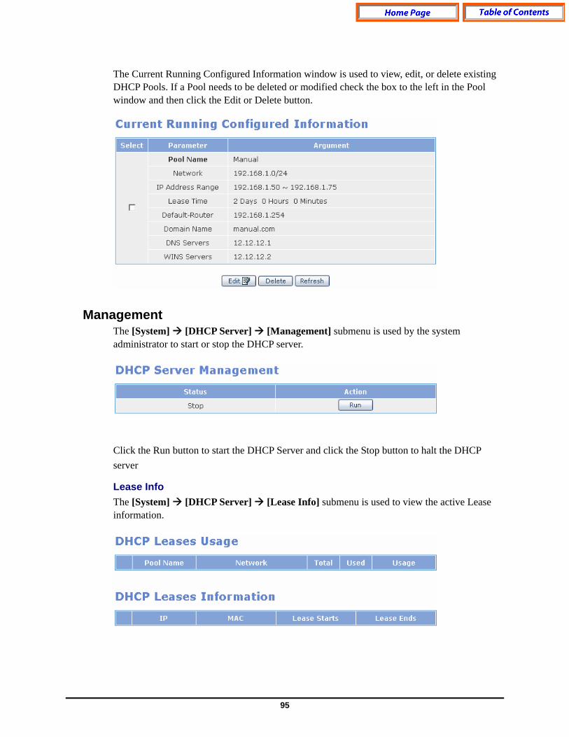
95
The Current Running Configured Information window is used to view, edit, or delete existing DHCP Pools. If a Pool needs to be deleted or modified check the box to the left in the Pool window and then click the Edit or Delete button.
Management The [System] [DHCP Server] [Management] submenu is used by the system administrator to start or stop the DHCP server.
Click the Run button to start the DHCP Server and click the Stop button to halt the DHCP server
Lease Info The [System] [DHCP Server] [Lease Info] submenu is used to view the active Lease information.
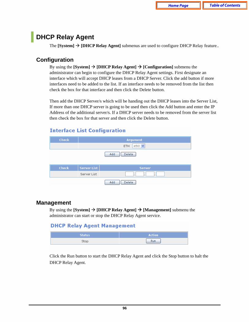
96
DHCP Relay Agent The [System] [DHCP Relay Agent] submenus are used to configure DHCP Relay feature..
Configuration By using the [System] [DHCP Relay Agent] [Configuration] submenu the administrator can begin to configure the DHCP Relay Agent settings. First designate an interface which will accept DHCP leases from a DHCP Server. Click the add button if more interfaces need to be added to the list. If an interface needs to be removed from the list then check the box for that interface and then click the Delete button. Then add the DHCP Server/s which will be handing out the DHCP leases into the Server List, If more than one DHCP server is going to be used then click the Add button and enter the IP Address of the additional server/s. If a DHCP server needs to be removed from the server list then check the box for that server and then click the Delete button.
Management By using the [System] [DHCP Relay Agent] [Management] submenu the administrator can start or stop the DHCP Relay Agent service. Click the Run button to start the DHCP Relay Agent and click the Stop button to halt the DHCP Relay Agent.
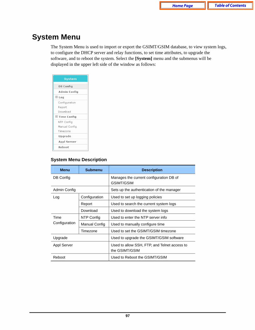
97
System Menu The System Menu is used to import or export the GSIMT/GSIM database, to view system logs, to configure the DHCP server and relay functions, to set time attributes, to upgrade the software, and to reboot the system. Select the [System] menu and the submenus will be displayed in the upper left side of the window as follows:
System Menu Description
Menu Submenu Description
DB Config Manages the current configuration DB of GSIMT/GSIM
Admin Config Sets up the authentication of the manager
Configuration Used to set up logging policies
Report Used to search the current system logs
Log
Download Used to download the system logs
NTP Config Used to enter the NTP server info
Manual Config Used to manually configure time
Time Configuration
Timezone Used to set the GSIMT/GSIM timezone
Upgrade Used to upgrade the GSIMT/GSIM software
Appl Server Used to allow SSH, FTP, and Telnet access to the GSIMT/GSIM
Reboot Used to Reboot the GSIMT/GSIM
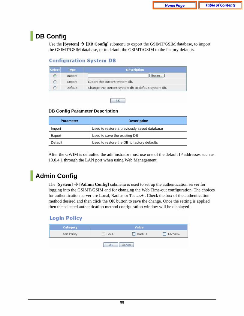
98
DB Config Use the [System] [DB Config] submenu to export the GSIMT/GSIM database, to import the GSIMT/GSIM database, or to default the GSIMT/GSIM to the factory defaults. DB Config Parameter Description
Parameter Description
Import Used to restore a previously saved database
Export Used to save the existing DB
Default Used to restore the DB to factory defaults
After the GWIM is defaulted the adminstrator must use one of the default IP addresses such as 10.0.4.1 through the LAN port when using Web Management.
Admin Config The [System] [Admin Config] submenu is used to set up the authentication server for logging into the GSIMT/GSIM and for changing the Web Time-out configuration. The choices for authentication server are Local, Radius or Taccas+ . Check the box of the authentication method desired and then click the OK button to save the change. Once the setting is applied then the selected authentication method configuration window will be displayed.
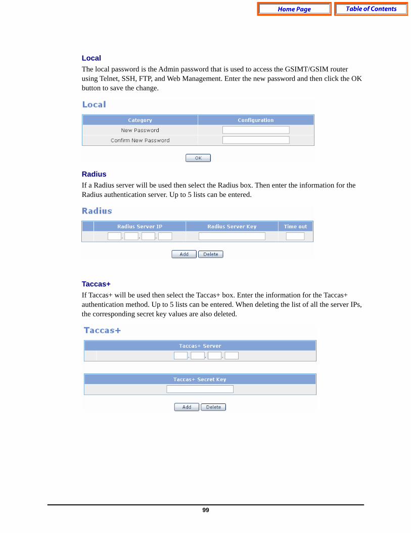
99
Local The local password is the Admin password that is used to access the GSIMT/GSIM router using Telnet, SSH, FTP, and Web Management. Enter the new password and then click the OK button to save the change.
Radius If a Radius server will be used then select the Radius box. Then enter the information for the Radius authentication server. Up to 5 lists can be entered.
Taccas+ If Taccas+ will be used then select the Taccas+ box. Enter the information for the Taccas+ authentication method. Up to 5 lists can be entered. When deleting the list of all the server IPs, the corresponding secret key values are also deleted.
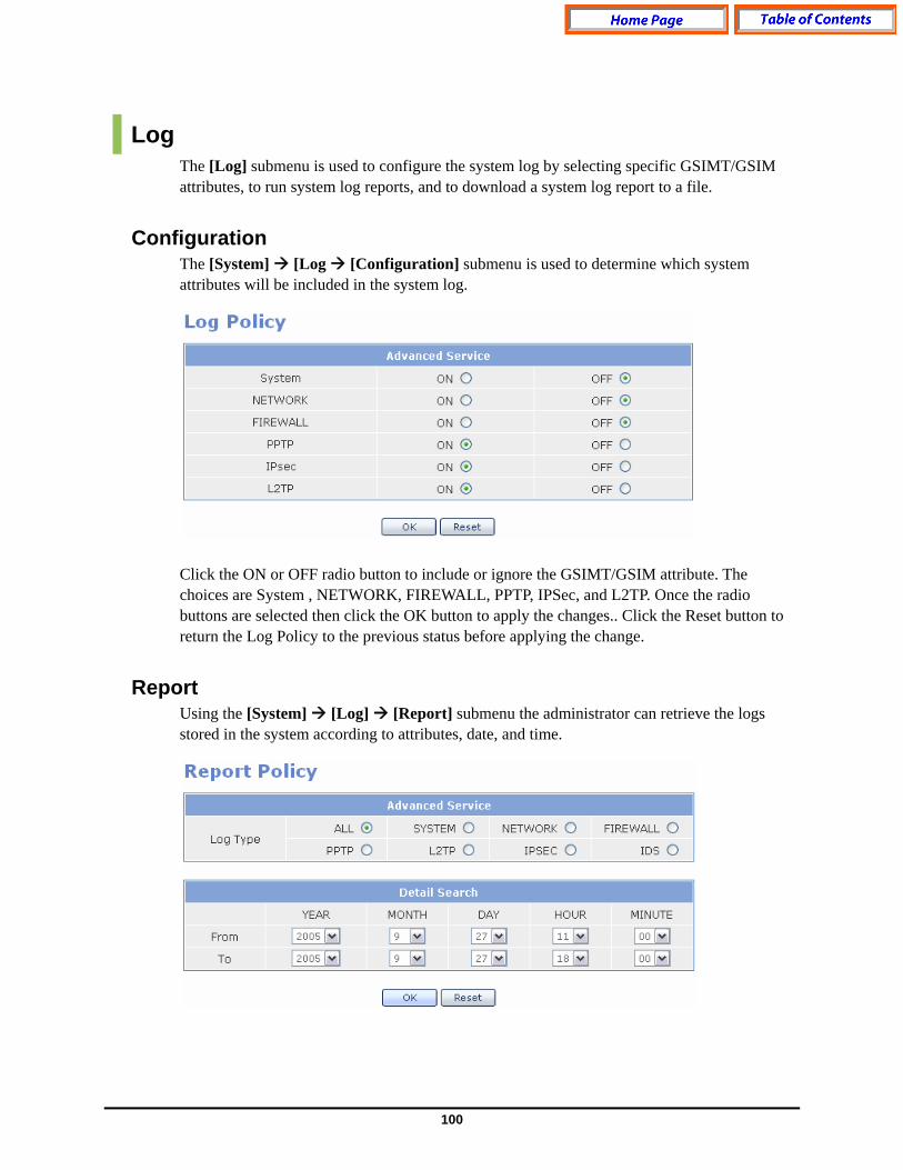
100
Log The [Log] submenu is used to configure the system log by selecting specific GSIMT/GSIM attributes, to run system log reports, and to download a system log report to a file.
Configuration The [System] [Log [Configuration] submenu is used to determine which system attributes will be included in the system log. Click the ON or OFF radio button to include or ignore the GSIMT/GSIM attribute. The choices are System , NETWORK, FIREWALL, PPTP, IPSec, and L2TP. Once the radio buttons are selected then click the OK button to apply the changes.. Click the Reset button to return the Log Policy to the previous status before applying the change.
Report Using the [System] [Log] [Report] submenu the administrator can retrieve the logs stored in the system according to attributes, date, and time.

101
Click the radio button for the desired log type and then select the date and time. Then click the OK button to run the report. Click the Reset button to return the log report settings to default.
Download
Using the [System] [Log] [Download] submenu the administrator can download a log report to a PC. Simply press the Download button and the system log will be downloaded in the form of a compressed file.
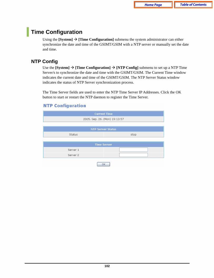
102
Time Configuration Using the [System] [Time Configuration] submenu the system administrator can either synchronize the date and time of the GSIMT/GSIM with a NTP server or manually set the date and time.
NTP Config Use the [System] [Time Configuration] [NTP Config] submenu to set up a NTP Time Server/s to synchronize the date and time with the GSIMT/GSIM. The Current Time window indicates the current date and time of the GSIMT/GSIM. The NTP Server Status window indicates the status of NTP Server synchronization process. The Time Server fields are used to enter the NTP Time Server IP Addresses. Click the OK button to start or restart the NTP daemon to register the Time Server.

103
Manual Config By using the [System] [Time Configuration] [Manual Config] submenu the administrator can manually set and modify the date and time of the GSIMT/GSIM. In the Date/Time Configuration window enter the desired date and time and then click the OK button to save the changes. The new date and time will be displayed in the Current Time window. In order to synchronize the date and time of the system with the MP40 then check the Set by C/S box and then click the OK button to save the change..
Timezone By using the [System] [Time Configuration] [Timezone] submenu the administrator can change Time Zones by selecting the desired timezone and then by clicking the OK button to save the change.

104
Upgrade Upgrading the GSIMT/GSIM software is performed using the [System] [Upgrade] submenu. First obtain the appropriate upgrade files . Then enter the new software package version number in the Package Version field. Then select one of the three types of upgrade methods (TFTP, HTTP, or Local). If the Upgrde method is TFTP or HTTP enter the correct IP address of the server. Then click the OK button to start the upgrade process.
Appl Server Using the [System] [Appl Server] submenu the administrator can control remote access to the GSIMT/GSIM using SSH, FTP and Telnet. In order to secure the system from hackers Samsung recommends that these are disabled and only turned on when the administrator needs to use them for debugging, and uploading or downloading files. Check the box of the access method and then click the OK button to save the change.
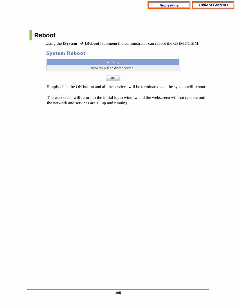
105
Reboot Using the [System] [Reboot] submenu the administrator can reboot the GSIMT/GSIM.
Simply click the OK button and all the services will be terminated and the system will reboot. The webscreen will return to the initial login window and the webscreen will not operate until the network and services are all up and running
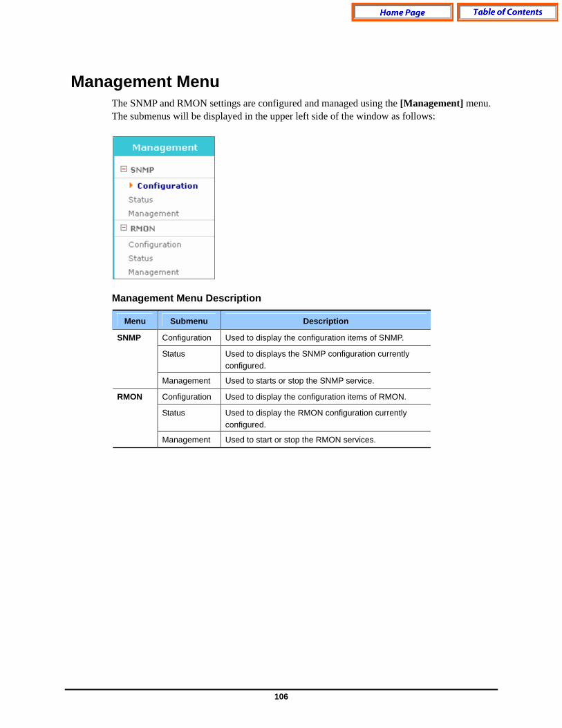
106
Management Menu The SNMP and RMON settings are configured and managed using the [Management] menu. The submenus will be displayed in the upper left side of the window as follows:
Management Menu Description
Menu Submenu Description
Configuration Used to display the configuration items of SNMP.
Status Used to displays the SNMP configuration currently configured.
SNMP
Management Used to starts or stop the SNMP service.
Configuration Used to display the configuration items of RMON.
Status Used to display the RMON configuration currently configured.
RMON
Management Used to start or stop the RMON services.

107
SNMP Configuration
SNMP is a set of protocols used for managing complex networks. The [SNMP] [Configuration] submenu is used by the administrator to enter SNMP System Options, SNMP Community information, SNMP v3 User information, and Trap Manager information. Once all the changes are entered then click the Save button at the bottom of the window. Click the Reset button to reset the configuration.
System Option The following window is used to set up the SNMP System Options.
SNMP System Option Parameter Description
Parameter Description
Location Used to enter the information for System Location
Contact Used to enter the information for System Contact
Name Used to enter the information for System Name
Engine ID Used to enter the information for System Engine ID
Community The following window is used to add new community information used in SNMP v1/2c.
Community Parameter Description
Parameter Description
New Community name Used to fill in the new community name being added
Community Network Used to set up new community network
Access Used to set up the access authority.

108
SNMPv3 Administrator Add The following window is used to enter the SNMPv3 Administrator v3 information.
SNMP v3 Parameter Description
Parameter Description
Administrator Name Used to enter the new administrator’s name
Administrator Password
Used to enter the new administrator’s password (8 alphanumeric characters)
Authentication Used to set up the authentication method.
Encryption Used to set up the ciphering method.
Access Set up access authority.
Trap Manager The following window is used to set up the IP address used to transmit a trap. Up to five IP addresses can be entered.
Trap Manager Parameter Description
Parameter Description
IP Address Used to set up a new Trap IP Address
Community Name Used to set up a community to be used for transmitting to the Trap IP Address added.
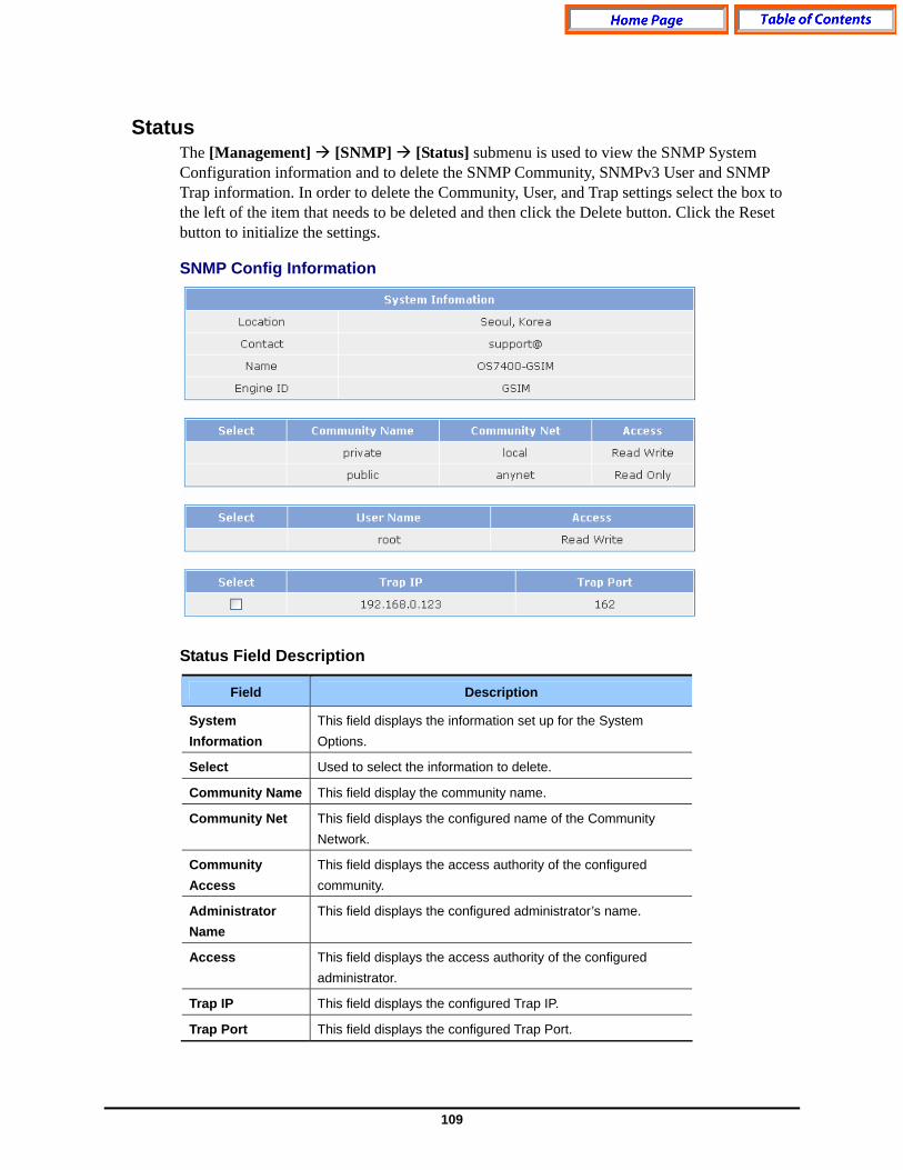
109
Status The [Management] [SNMP] [Status] submenu is used to view the SNMP System Configuration information and to delete the SNMP Community, SNMPv3 User and SNMP Trap information. In order to delete the Community, User, and Trap settings select the box to the left of the item that needs to be deleted and then click the Delete button. Click the Reset button to initialize the settings.
SNMP Config Information Status Field Description
Field Description
System Information
This field displays the information set up for the System Options.
Select Used to select the information to delete.
Community Name This field display the community name.
Community Net This field displays the configured name of the Community Network.
Community Access
This field displays the access authority of the configured community.
Administrator Name
This field displays the configured administrator’s name.
Access This field displays the access authority of the configured administrator.
Trap IP This field displays the configured Trap IP.
Trap Port This field displays the configured Trap Port.
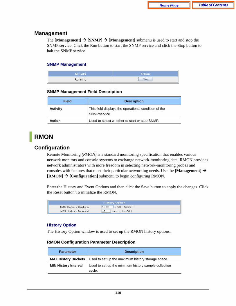
110
Management The [Management] [SNMP] [Management] submenu is used to start and stop the SNMP service. Click the Run button to start the SNMP service and click the Stop button to halt the SNMP service.
SNMP Management
SNMP Management Field Description
Field Description
Activity This field displays the operational condition of the SNMPservice.
Action Used to select whether to start or stop SNMP.
RMON Configuration
Remote Monitoring (RMON) is a standard monitoring specification that enables various network monitors and console systems to exchange network-monitoring data. RMON provides network administrators with more freedom in selecting network-monitoring probes and consoles with features that meet their particular networking needs. Use the [Management] [RMON] [Configuration] submenu to begin configuring RMON. Enter the History and Event Options and then click the Save button to apply the changes. Click the Reset button To initialize the RMON.
History Option The History Option window is used to set up the RMON history options. RMON Configuration Parameter Description
Parameter Description
MAX History Buckets Used to set up the maximum history storage space.
MIN History Interval Used to set up the minimum history sample collection cycle.

111
Event Options The Event Options window is used to set up the RMON event options.
RMON Event Options Parameter Description
Parameter Description
Max Event Logs Used to set up the maximum number of Event Logs.
Status The [Management] [RMON] [Status] submenu is used to view the RMON System Configuration.
RMON Global Status Field Description
Field Description
MAX History Buckets
This field displays the maximum history storage space that has been set up.
Granted History Buckets
This field displays the history storage space that is currently allocated.
Used History Buckets
This field displays the history storage space that is currently used.
MIN History Interval
This field displays the minimum history sample collection cycle.
Max Event Logs This field displays the maximum number of logs that are set up.
Saved Event Logs This field displays the number of logs that is currently stored.
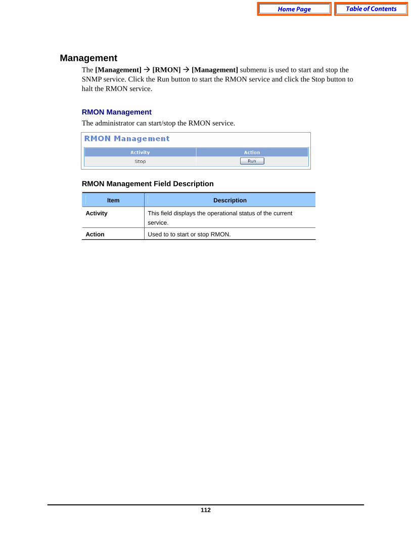
112
Management The [Management] [RMON] [Management] submenu is used to start and stop the SNMP service. Click the Run button to start the RMON service and click the Stop button to halt the RMON service.
RMON Management The administrator can start/stop the RMON service.
RMON Management Field Description
Item Description
Activity This field displays the operational status of the current service.
Action Used to to start or stop RMON.
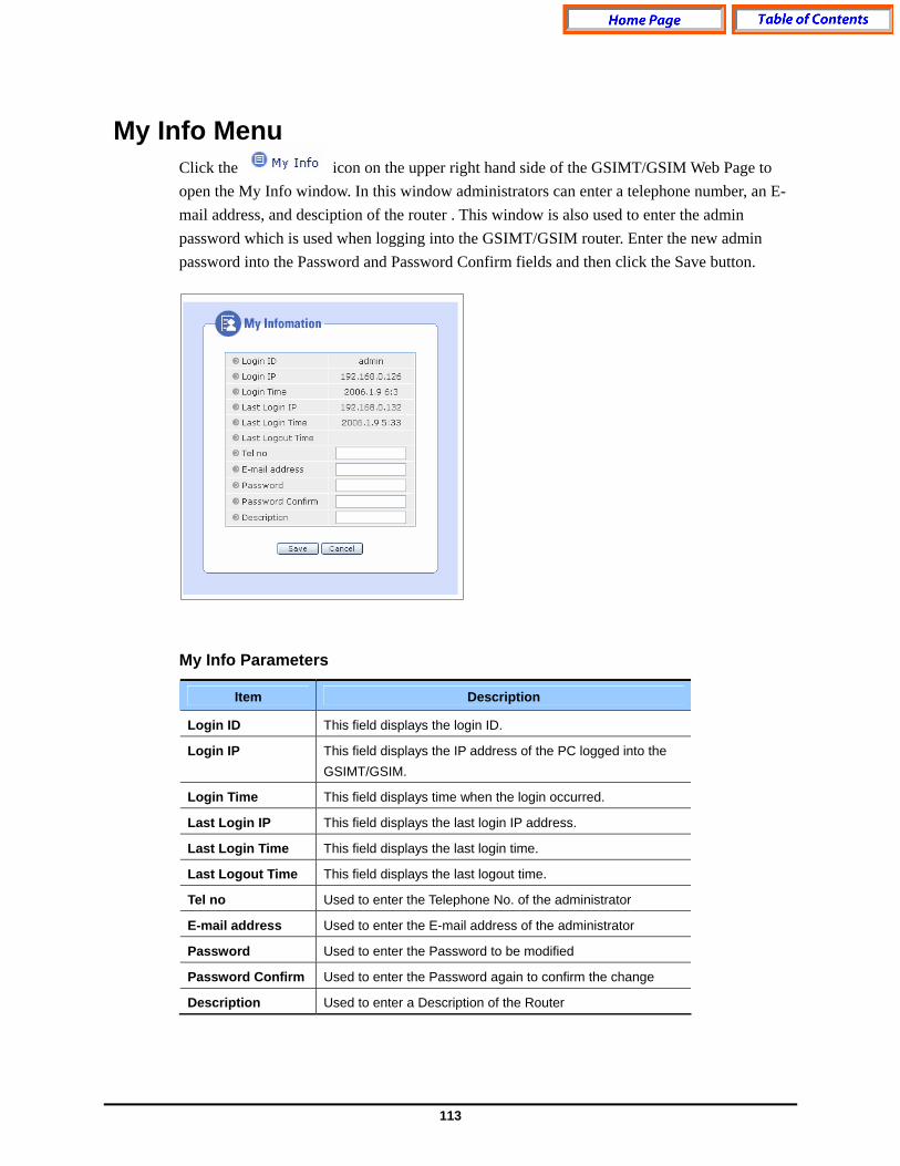
113
My Info Menu Click the icon on the upper right hand side of the GSIMT/GSIM Web Page to open the My Info window. In this window administrators can enter a telephone number, an E-mail address, and desciption of the router . This window is also used to enter the admin password which is used when logging into the GSIMT/GSIM router. Enter the new admin password into the Password and Password Confirm fields and then click the Save button.
My Info Parameters
Item Description
Login ID This field displays the login ID.
Login IP This field displays the IP address of the PC logged into the GSIMT/GSIM.
Login Time This field displays time when the login occurred.
Last Login IP This field displays the last login IP address.
Last Login Time This field displays the last login time.
Last Logout Time This field displays the last logout time.
Tel no Used to enter the Telephone No. of the administrator
E-mail address Used to enter the E-mail address of the administrator
Password Used to enter the Password to be modified
Password Confirm Used to enter the Password again to confirm the change
Description Used to enter a Description of the Router
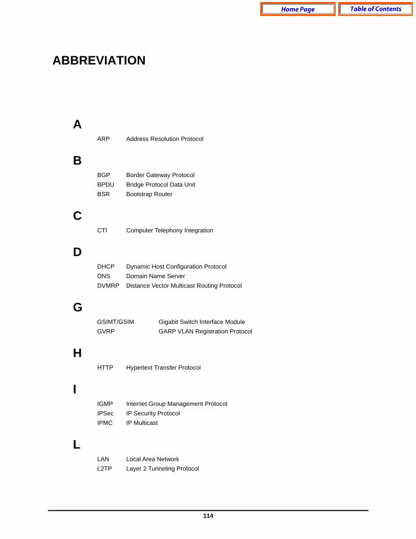
114
ABBREVIATION
A ARP Address Resolution Protocol
B BGP Border Gateway Protocol BPDU Bridge Protocol Data Unit BSR Bootstrap Router
C CTI Computer Telephony Integration
D DHCP Dynamic Host Configuration Protocol DNS Domain Name Server DVMRP Distance Vector Multicast Routing Protocol
G GSIMT/GSIM Gigabit Switch Interface Module GVRP GARP VLAN Registration Protocol
H HTTP Hypertext Transfer Protocol
I IGMP Internet Group Management Protocol IPSec IP Security Protocol IPMC IP Multicast
L LAN Local Area Network L2TP Layer 2 Tunneling Protocol
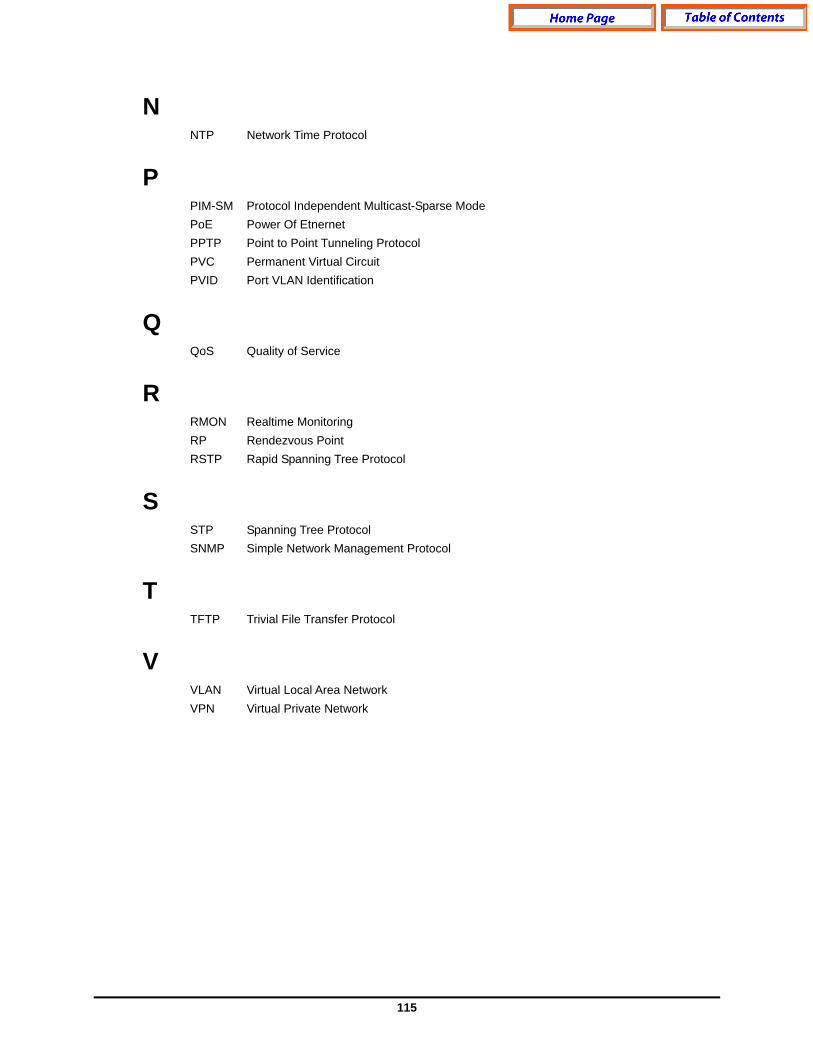
115
N NTP Network Time Protocol
P PIM-SM Protocol Independent Multicast-Sparse Mode PoE Power Of Etnernet PPTP Point to Point Tunneling Protocol PVC Permanent Virtual Circuit PVID Port VLAN Identification
Q QoS Quality of Service
R RMON Realtime Monitoring RP Rendezvous Point RSTP Rapid Spanning Tree Protocol
S STP Spanning Tree Protocol SNMP Simple Network Management Protocol
T TFTP Trivial File Transfer Protocol
V VLAN Virtual Local Area Network VPN Virtual Private Network