Embed Size (px)
Citation preview
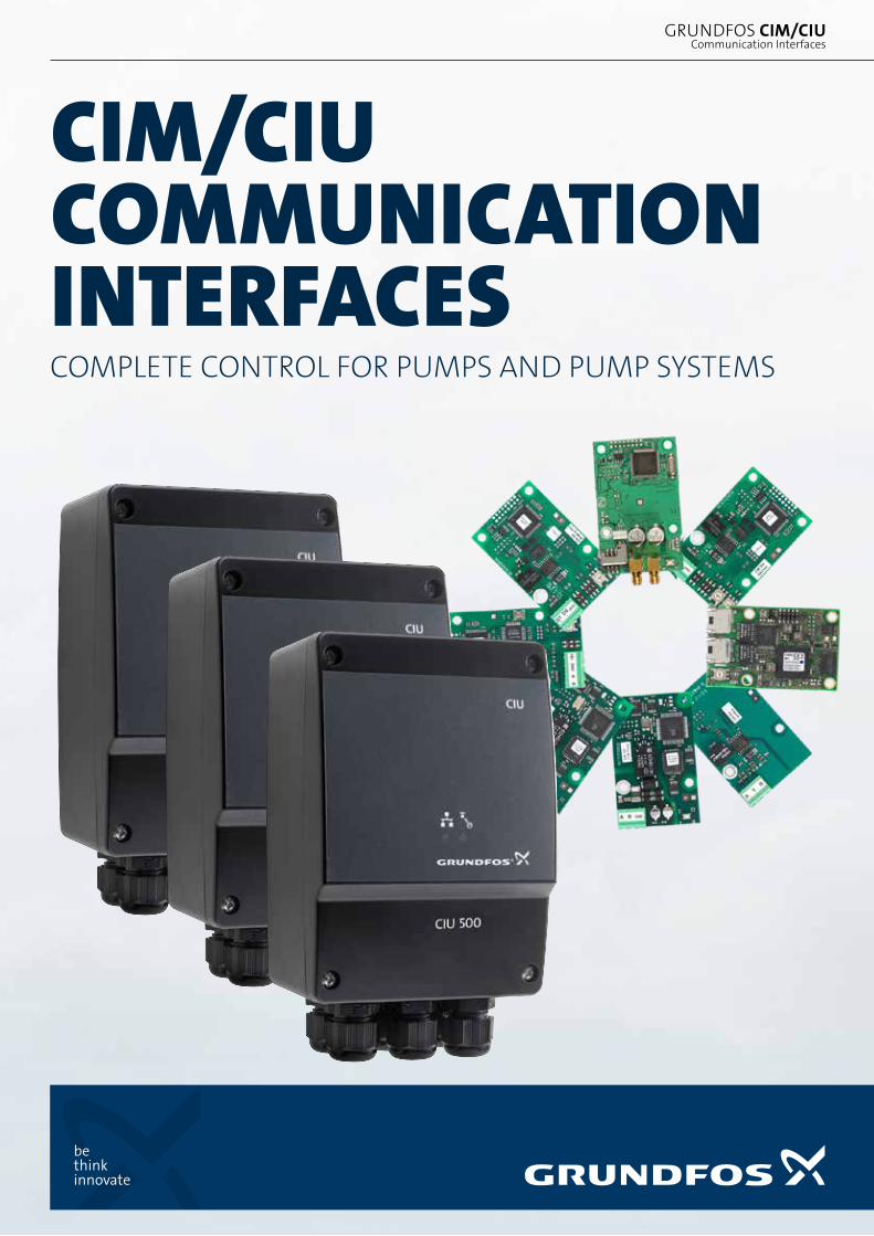
CIM/CIU COMMUNICATION INTERFACESCOMPLETE CONTROL FOR PUMPS AND PUMP SYSTEMS
Communication InterfacesGRUNDFOS CIM/CIU
2
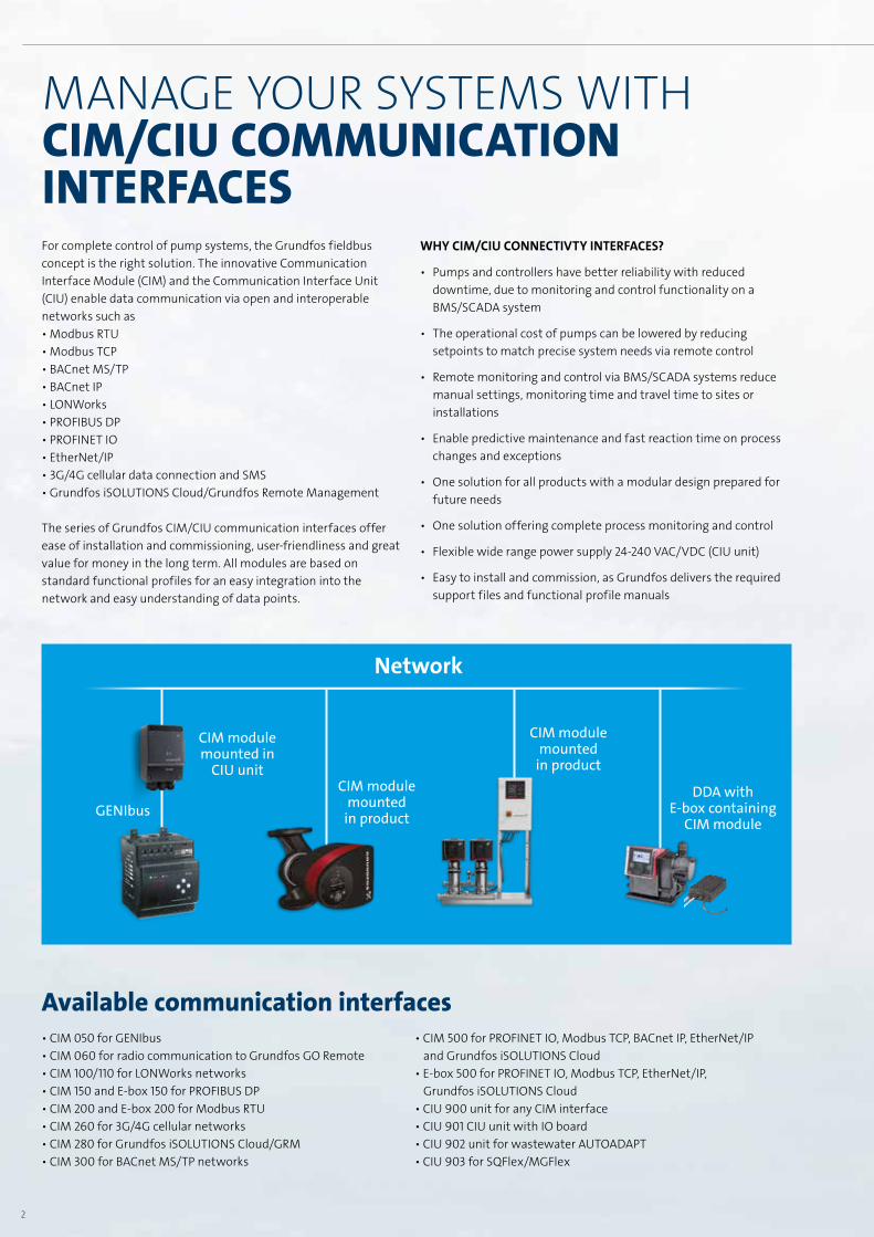
MANAGE YOUR SYSTEMS WITH CIM/CIU COMMUNICATION INTERFACES
Available communication interfaces
For complete control of pump systems, the Grundfos fieldbus concept is the right solution. The innovative Communication Interface Module (CIM) and the Communication Interface Unit (CIU) enable data communication via open and interoperable networks such as • Modbus RTU• Modbus TCP• BACnet MS/TP• BACnet IP• LONWorks• PROFIBUS DP• PROFINET IO• EtherNet/IP• 3G/4G cellular data connection and SMS• Grundfos iSOLUTIONS Cloud/Grundfos Remote Management
The series of Grundfos CIM/CIU communication interfaces offer ease of installation and commissioning, user-friendliness and great value for money in the long term. All modules are based on standard functional profiles for an easy integration into the network and easy understanding of data points.
WHY CIM/CIU CONNECTIVTY INTERFACES?
• Pumps and controllers have better reliability with reduced downtime, due to monitoring and control functionality on a BMS/SCADA system
• The operational cost of pumps can be lowered by reducing setpoints to match precise system needs via remote control
• Remote monitoring and control via BMS/SCADA systems reduce manual settings, monitoring time and travel time to sites or installations
• Enable predictive maintenance and fast reaction time on process changes and exceptions
• One solution for all products with a modular design prepared for future needs
• One solution offering complete process monitoring and control
• Flexible wide range power supply 24-240 VAC/VDC (CIU unit)
• Easy to install and commission, as Grundfos delivers the required support files and functional profile manuals
• CIM 050 for GENIbus• CIM 060 for radio communication to Grundfos GO Remote• CIM 100/110 for LONWorks networks• CIM 150 and E-box 150 for PROFIBUS DP• CIM 200 and E-box 200 for Modbus RTU• CIM 260 for 3G/4G cellular networks• CIM 280 for Grundfos iSOLUTIONS Cloud/GRM• CIM 300 for BACnet MS/TP networks
• CIM 500 for PROFINET IO, Modbus TCP, BACnet IP, EtherNet/IP and Grundfos iSOLUTIONS Cloud
• E-box 500 for PROFINET IO, Modbus TCP, EtherNet/IP, Grundfos iSOLUTIONS Cloud
• CIU 900 unit for any CIM interface• CIU 901 CIU unit with IO board• CIU 902 unit for wastewater AUTOADAPT• CIU 903 for SQFlex/MGFlex
CIM & CIU COMMUNICATION INTERFACES FIELDBUS COMMUNICATION
Network
CIM module mounted in
CIU unit
GENIbus
CIM module mounted
in product
CIM module mounted
in product
DDA with E-box containing
CIM module
3
Available communication interfaces
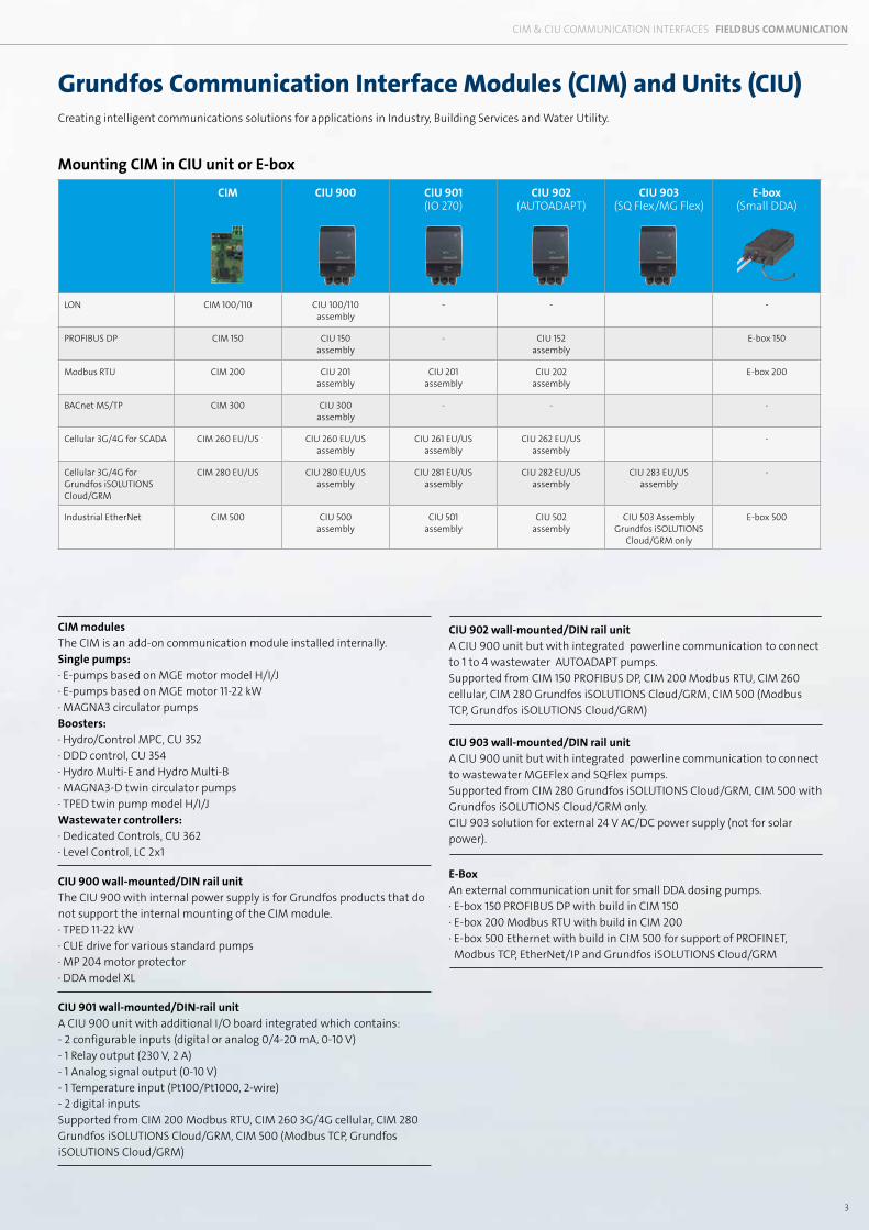
Grundfos Communication Interface Modules (CIM) and Units (CIU)
CIM modules The CIM is an add-on communication module installed internally. Single pumps: · E-pumps based on MGE motor model H/I/J · E-pumps based on MGE motor 11-22 kW · MAGNA3 circulator pumps Boosters: · Hydro/Control MPC, CU 352 · DDD control, CU 354 · Hydro Multi-E and Hydro Multi-B · MAGNA3-D twin circulator pumps · TPED twin pump model H/I/J Wastewater controllers: · Dedicated Controls, CU 362 · Level Control, LC 2x1
CIU 900 wall-mounted/DIN rail unit The CIU 900 with internal power supply is for Grundfos products that do not support the internal mounting of the CIM module. · TPED 11-22 kW · CUE drive for various standard pumps · MP 204 motor protector · DDA model XL
CIU 901 wall-mounted/DIN-rail unit A CIU 900 unit with additional I/O board integrated which contains: - 2 configurable inputs (digital or analog 0/4-20 mA, 0-10 V) - 1 Relay output (230 V, 2 A) - 1 Analog signal output (0-10 V) - 1 Temperature input (Pt100/Pt1000, 2-wire) - 2 digital inputs Supported from CIM 200 Modbus RTU, CIM 260 3G/4G cellular, CIM 280 Grundfos iSOLUTIONS Cloud/GRM, CIM 500 (Modbus TCP, Grundfos iSOLUTIONS Cloud/GRM)
CIU 902 wall-mounted/DIN rail unit A CIU 900 unit but with integrated powerline communication to connect to 1 to 4 wastewater AUTOADAPT pumps.Supported from CIM 150 PROFIBUS DP, CIM 200 Modbus RTU, CIM 260 cellular, CIM 280 Grundfos iSOLUTIONS Cloud/GRM, CIM 500 (Modbus TCP, Grundfos iSOLUTIONS Cloud/GRM)
CIU 903 wall-mounted/DIN rail unit A CIU 900 unit but with integrated powerline communication to connect to wastewater MGEFlex and SQFlex pumps.Supported from CIM 280 Grundfos iSOLUTIONS Cloud/GRM, CIM 500 with Grundfos iSOLUTIONS Cloud/GRM only. CIU 903 solution for external 24 V AC/DC power supply (not for solar power).
E-BoxAn external communication unit for small DDA dosing pumps.· E-box 150 PROFIBUS DP with build in CIM 150· E-box 200 Modbus RTU with build in CIM 200· E-box 500 Ethernet with build in CIM 500 for support of PROFINET, Modbus TCP, EtherNet/IP and Grundfos iSOLUTIONS Cloud/GRM
CIM & CIU COMMUNICATION INTERFACES FIELDBUS COMMUNICATION
CIM CIU 900 CIU 901(IO 270)
CIU 902(AUTOADAPT)
CIU 903(SQ Flex/MG Flex)
E-box(Small DDA)
LON CIM 100/110 CIU 100/110assembly
- - -
PROFIBUS DP CIM 150 CIU 150assembly
- CIU 152assembly
E-box 150
Modbus RTU CIM 200 CIU 201assembly
CIU 201assembly
CIU 202assembly
E-box 200
BACnet MS/TP CIM 300 CIU 300assembly
- - -
Cellular 3G/4G for SCADA CIM 260 EU/US CIU 260 EU/USassembly
CIU 261 EU/USassembly
CIU 262 EU/USassembly
-
Cellular 3G/4G for Grundfos iSOLUTIONS Cloud/GRM
CIM 280 EU/US CIU 280 EU/USassembly
CIU 281 EU/USassembly
CIU 282 EU/USassembly
CIU 283 EU/USassembly
-
Industrial EtherNet CIM 500 CIU 500assembly
CIU 501assembly
CIU 502assembly
CIU 503 AssemblyGrundfos iSOLUTIONS
Cloud/GRM only
E-box 500
Mounting CIM in CIU unit or E-box
Creating intelligent communications solutions for applications in Industry, Building Services and Water Utility.
4
MAGNA3-D Twin pump
2)
MAGNA 3 TPED 11-22 kW Twin
pump
Twin pumpTPED Model
H/I/J 1)
E-pump MGE model
H/I/J + 11-22 kW
CUE + TPE 22-55 kW
Hydro MPC (CU 352)
Multi-E MGE
11-22 kW model G/F
Multi-EModel
H/I/J 1)
MP 204 Dedicated Controls (CU 362)
Wastewater AUTOADAPT
1-4 pumps
LC 2x1 DDA dosing 3)
GENIbus
CIM 050 CIM 050
built-in built-in built-in built-in
CIM 050
built-in built-in built-in
CIM 050CIU 902 + CIM 050
built-in
LON
CIM 110 CIM 1002x CIU 900
+ 2x CIM 100 CIM 110 CIM 100 CIU 900 + CIM 100 CIM 110
CIU 900 + CIM 100 CIM 110
PROFIBUS DP
CIM 150 CIM 1502x CIU 900 +
2x CIM 150 CIM 150 CIM 150CIU 900 +
CIM 150 CIM 150CIU 900 +
CIM 150 CIM 150CIU 900 +
CIM 150 CIM 150CIU 902 + CIM 150 CIM 150
CIU 900 + CIM 150 or E-box 150
PROFINET IO
CIM 500 CIM 5002x CIU 900 + 2x CIM 500 CIM 500 CIM 500
CIU 900 + CIM 500 CIM 500
CIU 900 + CIM 500 CIM 500
CIU 900 + CIM 500 CIM500
CIU 902 + CIM 500 CIM500
CIU 900 + CIM 500 or E-box 500
Modbus TCP
CIM 500 CIM 5002x CIU 900 + 2x CIM 500 CIM 500 CIM 500
CIU 900 + CIM 500 CIM 500
CIU 900 + CIM 500 CIM 500
CIU 900 + CIM 500 CIM 500
CIU 902 + CIM 500 CIM 500
CIU 900 + CIM 500 or E-box 500
Modbus RTU
CIM 200 CIM 2002x CIU 900 + 2x CIM 200 CIM 200 CIM 200
CIU 900 + CIM 200 CIM 200
CIU 900 + CIM 200 CIM 200
CIU 900 + CIM 200 CIM 200
CIU 902 + CIM 200 CIM 200
CIU 900 + CIM 200 or E-box 200
EtherNet/IP
CIM 500 CIM 500
2x CIU 900 + 2x
CIM 500 CIM 500 CIM 500CIU 900 + CIM 500 CIM 500
CIU 900 + CIM 500 CIM 500
CIU 900 + CIM 500 or E-box 500
BACnet MS/TP
CIM 300 CIM 3002x CIU 900 + 2x CIM 300 CIM 300 CIM 300
CIU 900 + CIM 300 CIM 300
CIU 900 + CIM 300 CIM 300
BACnet IP
CIM 500 CIM 5002x CIU 900 + 2x CIM 500 CIM 500 CIM 500
CIU 900 + CIM 500 CIM 500
CIU 900 + CIM 500 CIM 500
Grundfos iSOLUTIONS Cloud4)
CIM 280/CIM 500
CIM 280/CIM 500
2x CIU 900 + 2x CIM 280
/ 2x CIM 500
CIM 280/CIM 500
CIM 280/CIM 500
CIU 900 + CIM 280/CIM 500
CIM 280/CIM 500
CIU 900 + CIM 280/CIM 500
CIM 280/CIM 500
CIU 900 + CIM 280/CIM 500
CIM 280/CIM 500
CIU 902 + CIM 280/CIM 500
CIM 280/CIM 500
CIU 900 + CIM 500 or E-box 500
Cellular data connection for SCADA and SMS4)
CIM 260 CIM 260
2x CIU 900 + 2x
CIM 260 CIM 260 CIM 260CIU 900 + CIM 260 CIM 260
CIU 900 + CIM 260 CIM 260
CIU 900 + CIM 260 CIM 260
CIU 902 + CIM 260 CIM 260
Radio to Grundfos GO Remote
built-in built-in built-in built-in built-in
CIM 060CIU 902 + CIM 060
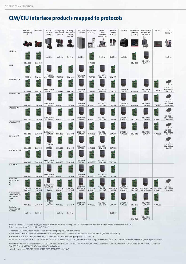
Note: To create a CIU xxx solution, you need to order a CIU 900 + the required CIM xxx interface and mount the CIM xxx interface into CIU 900. This is the same for a CIU xx1, CIU xx2, CIU xx3.
1) A second CIM module can optionally be mounted in pump no. 2 for redundancy2) MAGNA3-D model D requires 1x CIM in master head, MAGNA3-D models A-C require a CIM in each head (for LON 2x CIM 100)3) Small DDA uses the E-box, whereas DDA XL uses the CIU unit plus the appropriate CIM module4) CIM 260 3G/4G cellular and CIM 280 Grundfos iSOLUTIONS Cloud/GRM 3G/4G are available in regional versions for EU and for USA (consider needed 3G/4G frequency bands)
Note: Hydro Multi-B is supported by CIM 050 GENIbus, CIM 110 LON, CIM 200 Modbus RTU, CIM 300 BACnet MS/TP, CIM 500 (Modbus TCP, BACnet IP), CIM 260 3G/4G cellular, CIM 280 Grundfos iSOLUTIONS Cloud/GRM 3G/4G cellular.Note: E-pumps are CRE/CRNE/CRIE, MTRE, CME, TPE2/TPE3, NBE/NKE.
CIM/CIU interface products mapped to protocols
PROTOCOLS MAINLY USED IN BUILDING SERVICES FIELDBUS COMMUNICATIONFIELDBUS COMMUNICATION
5
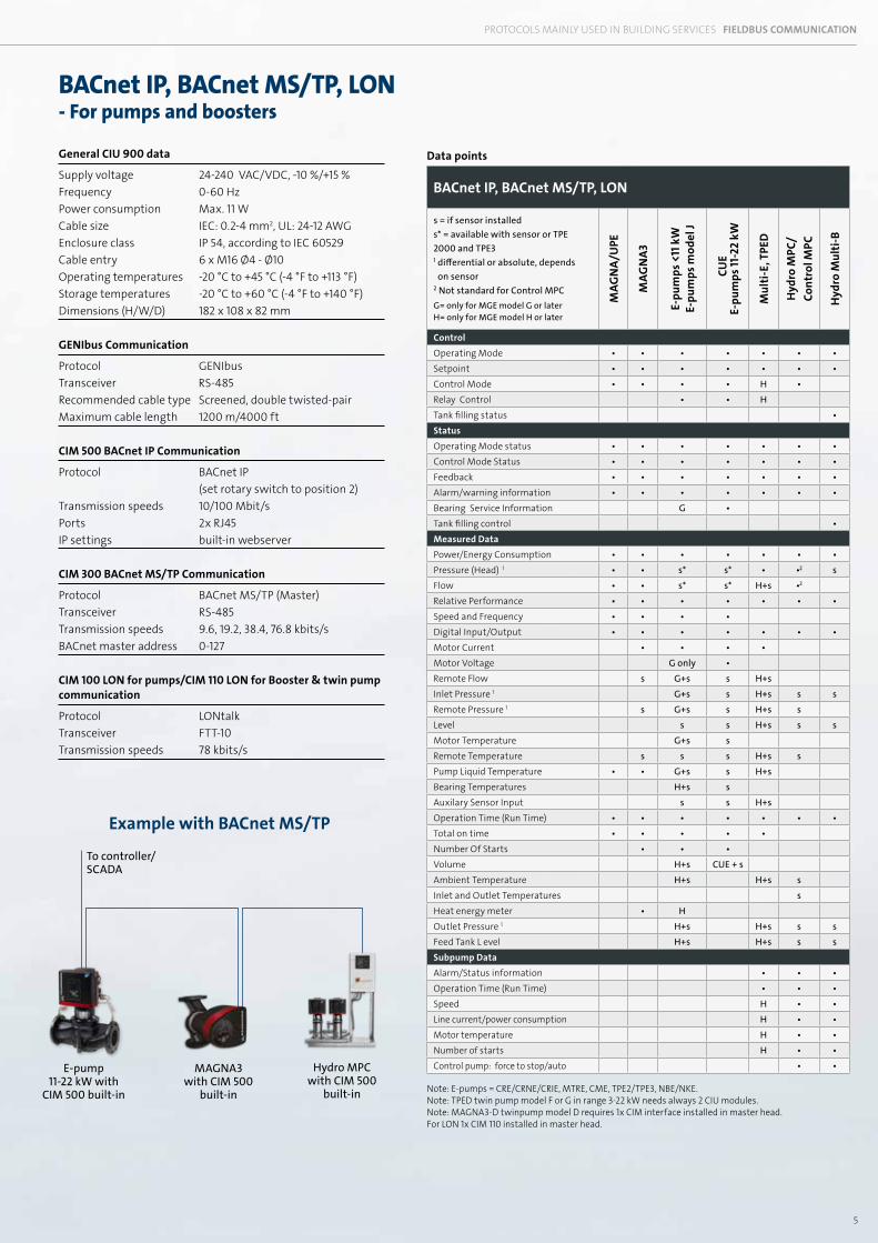
Example with BACnet MS/TP
E-pump 11-22 kW with
CIM 500 built-in
MAGNA3with CIM 500
built-in
Hydro MPC with CIM 500
built-in
General CIU 900 data
Supply voltage 24-240 VAC/VDC, -10 %/+15 %Frequency 0-60 HzPower consumption Max. 11 WCable size IEC: 0.2-4 mm2, UL: 24-12 AWGEnclosure class IP 54, according to IEC 60529Cable entry 6 x M16 Ø4 - Ø10Operating temperatures -20 °C to +45 °C (-4 °F to +113 °F)Storage temperatures -20 °C to +60 °C (-4 °F to +140 °F)Dimensions (H/W/D) 182 x 108 x 82 mm
GENIbus Communication
Protocol GENIbusTransceiver RS-485Recommended cable type Screened, double twisted-pairMaximum cable length 1200 m/4000 ft
CIM 500 BACnet IP Communication
Protocol BACnet IP (set rotary switch to position 2)Transmission speeds 10/100 Mbit/sPorts 2x RJ45 IP settings built-in webserver CIM 300 BACnet MS/TP Communication
Protocol BACnet MS/TP (Master) Transceiver RS-485 Transmission speeds 9.6, 19.2, 38.4, 76.8 kbits/s BACnet master address 0-127 CIM 100 LON for pumps/CIM 110 LON for Booster & twin pump communication
Protocol LONtalk Transceiver FTT-10 Transmission speeds 78 kbits/s
Data points
BACnet IP, BACnet MS/TP, LON
s = if sensor installeds* = available with sensor or TPE 2000 and TPE31 differential or absolute, depends
on sensor 2 Not standard for Control MPCG= only for MGE model G or laterH= only for MGE model H or later
MAG
NA/
UPE
MAG
NA
3
E-pu
mps
<11
kW
E-pu
mps
mod
el J
CU
EE-
pum
ps 11
-22
kW
Mul
ti-E
, TPE
D
Hyd
ro M
PC/
Cont
rol M
PC
Hyd
ro M
ulti
-B
ControlOperating Mode • • • • • • •Setpoint • • • • • • •Control Mode • • • • H •Relay Control • • HTank filling status •StatusOperating Mode status • • • • • • •Control Mode Status • • • • • • •Feedback • • • • • • •Alarm/warning information • • • • • • •Bearing Service Information G •Tank filling control •Measured DataPower/Energy Consumption • • • • • • •Pressure (Head) 1 • • s* s* • •2 sFlow • • s* s* H+s •2
Relative Performance • • • • • • •Speed and Frequency • • • •Digital Input/Output • • • • • • •Motor Current • • • •Motor Voltage G only •Remote Flow s G+s s H+sInlet Pressure 1 G+s s H+s s sRemote Pressure 1 s G+s s H+s sLevel s s H+s s sMotor Temperature G+s sRemote Temperature s s s H+s sPump Liquid Temperature • • G+s s H+sBearing Temperatures H+s sAuxilary Sensor Input s s H+sOperation Time (Run Time) • • • • • • •Total on time • • • • •Number Of Starts • • •Volume H+s CUE + sAmbient Temperature H+s H+s sInlet and Outlet Temperatures sHeat energy meter • HOutlet Pressure 1 H+s H+s s sFeed Tank L evel H+s H+s s sSubpump DataAlarm/Status information • • •Operation Time (Run Time) • • •Speed H • •Line current/power consumption H • •Motor temperature H • •Number of starts H • •Control pump: force to stop/auto • •
Note: E-pumps = CRE/CRNE/CRIE, MTRE, CME, TPE2/TPE3, NBE/NKE. Note: TPED twin pump model F or G in range 3-22 kW needs always 2 CIU modules.Note: MAGNA3-D twinpump model D requires 1x CIM interface installed in master head. For LON 1x CIM 110 installed in master head.
PROTOCOLS MAINLY USED IN BUILDING SERVICES FIELDBUS COMMUNICATION
BACnet IP, BACnet MS/TP, LON- For pumps and boosters
To controller/SCADA
6
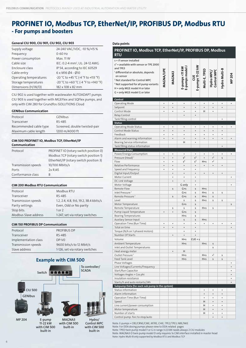
PROFINET IO, Modbus TCP, EtherNet/IP, PROFIBUS DP, Modbus RTU- For pumps and boosters
General CIU 900, CIU 901, CIU 902, CIU 903
Supply voltage 24-240 VAC/VDC, -10 %/+15 %Frequency 0-60 HzPower consumption Max. 11 WCable size IEC: 0.2-4 mm2, UL: 24-12 AWGEnclosure class IP 54, according to IEC 60529Cable entry 6 x M16 Ø4 - Ø10Operating temperatures -20 °C to +45 °C (-4 °F to +113 °F)Storage temperatures -20 °C to +60 °C (-4 °F to +140 °F)Dimensions (H/W/D) 182 x 108 x 82 mm CIU 902 is used together with wastewater AUTOADAPT pumps CIU 903 is used together with MGEFlex and SQFlex pumps, and only with CIM 280 for Grundfos iSOLUTIONS Cloud
GENIbus Communication
Protocol GENIbus Transceiver RS-485Recommended cable type Screened, double twisted-pairMaximum cable length 1200 m/4000 ft
CIM 500 PROFINET IO, Modbus TCP, EtherNet/IP Communication
Protocol PROFINET IO (rotary switch position 0) Modbus TCP (rotary switch position 1) EtherNet/IP (rotary switch position 3)Transmission speeds 10/100 Mbits/sPorts 2x RJ45Conformance class B
CIM 200 Modbus RTU Communication
Protocol Modbus RTU Transceiver RS-485 Transmission speeds 1.2, 2.4, 4.8, 9.6, 19.2, 38.4 kbits/s Parity settings Even, Odd or No parityStop bits. 1 or 2 Modbus Slave address 1-247, set via rotary switches CIM 150 PROFIBUS DP Communication
Protocol PROFIBUS DP Transceiver RS-485 Implementation class DP-V0 Transmission speeds 9600 bits/s to 12 Mbit/s Slave address 1-126, set via rotary switches
Example with CIM 500
E-pump 11-22 kW
with CIM 500 built-in
Hydro/ Control MPCwith CIM 500
built-in
Data points
PROFINET IO, Modbus TCP, EtherNet/IP, PROFIBUS DP, Modbus RTUs = if sensor installeds* = available with sensor or TPE 2000 and TPE31 differential or absolute, depends
on sensor2 Not standard for Control MPC3 Not supported for all pump variantsH = only MGE model H or laterG = only MGE model G or later
MAG
NA/
UPE
MAG
NA
3
E-pu
mps
<11
kW
E-pu
mps
mod
el J
CUE
E-pu
mps
11-2
2 kW
Mul
ti-E
, TPE
D
Hyd
ro M
PC/
Cont
rol M
PC
Hyd
ro M
ulti
-B
MP
204
ControlOperating Mode • • • • • • • •Setpoint • • • • • • •Control Mode • • • • H •Relay Control • •Tank filling control •StatusOperating Mode Status • • • • • • • •Control Mode Status • • • • • • •Feedback • • • • • • •Alarm and warning information • • • • • • • •Bearing Service information H •Tank filling status information •Measured DataPower/Energy Consumption • • • • • • • •Pressure (Head) 1 • • s* s* • •2 sFlow • • s* s* H+s •2
Relative Performance • • • • • • •Speed and Frequency • • • •Digital Input/Output • • • • • •Motor Current • • • •DC Link Voltage • • •Motor Voltage G only • •Remote Flow s G+s s H+sInlet Pressure 1 G+s s H+s s sRemote Pressure 1 s G+s s H+s sLevel s s H+s s sMotor Temperature G+s s sRemote Temperature s s s H+s sPump Liquid Temperature • • G+s sBearing Temperatures H+s sAuxilary Sensor Input s s H+sOperation Time (Run Time) • • • • • • • •Total on time • • • • •Torque (N/A on 1-phased motors) • •Number Of Starts • • •Volume H+s CUE + sAmbient Temperature H+s H+s sInlet and Outlet Temperatures sHeat energy meter • HOutlet Pressure 1 H+s H+s •2 sFeed Tank Level H+s H+s s sPhase Voltages •Line Voltages/Currents/Frequency •Start/Run Capacitor •Voltages Angles + Cos phi •Insulation resistance •Starts/h and auto restarts/24h •Subpump Data (for each sub pump in the system)Status information • • •Alarm information • • •Operation Time (Run Time) • • •Speed H • •Line current/power consumption H • •Motor temperature H • •Number of starts H • •Control pump: forc to stop/auto • •
MAGNA3 with CIM 500
built-inNote: E-pumps = CRE/CRNE/CME, MTRE, CHIE, TPE2/TPE3, NBE/NKENote: For DDA dosing pumps please view to DDA related pagesNote: TPED twin pump model F or G in range 3-22 kW needs always 2 CIU modulesNote: MAGNA3-D twin pump model D only requires 1x CIM interface installed in master headNote: Hydro Multi-B only supported by Modbus RTU and Modbus TCP
MP 204
CIU 500
GENIbus
USED FOR COMMUNICATION IN WASTEWATER FIELDBUS COMMUNICATIONFIELDBUS COMMUNICATION PROTOCOLS MAINLY USED AT INDUSTRIAL AUTOMATION AND WATER UTILITY
To controller/SCADASwitch
7
Example with CIM 500
USED FOR COMMUNICATION IN WASTEWATER FIELDBUS COMMUNICATION
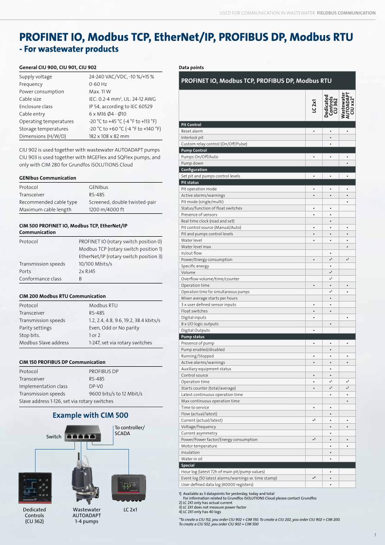
PROFINET IO, Modbus TCP, EtherNet/IP, PROFIBUS DP, Modbus RTU- For wastewater products
General CIU 900, CIU 901, CIU 902
Supply voltage 24-240 VAC/VDC, -10 %/+15 %Frequency 0-60 HzPower consumption Max. 11 WCable size IEC: 0.2-4 mm2, UL: 24-12 AWGEnclosure class IP 54, according to IEC 60529Cable entry 6 x M16 Ø4 - Ø10Operating temperatures -20 °C to +45 °C (-4 °F to +113 °F)Storage temperatures -20 °C to +60 °C (-4 °F to +140 °F)Dimensions (H/W/D) 182 x 108 x 82 mm CIU 902 is used together with wastewater AUTOADAPT pumps CIU 903 is used together with MGEFlex and SQFlex pumps, and only with CIM 280 for Grundfos iSOLUTIONS Cloud
GENIbus Communication
Protocol GENIbus Transceiver RS-485Recommended cable type Screened, double twisted-pairMaximum cable length 1200 m/4000 ft
CIM 500 PROFINET IO, Modbus TCP, EtherNet/IP Communication
Protocol PROFINET IO (rotary switch position 0) Modbus TCP (rotary switch position 1) EtherNet/IP (rotary switch position 3)Transmission speeds 10/100 Mbits/sPorts 2x RJ45Conformance class B
CIM 200 Modbus RTU Communication
Protocol Modbus RTU Transceiver RS-485 Transmission speeds 1.2, 2.4, 4.8, 9.6, 19.2, 38.4 kbits/s Parity settings Even, Odd or No parityStop bits. 1 or 2 Modbus Slave address 1-247, set via rotary switches CIM 150 PROFIBUS DP Communication
Protocol PROFIBUS DP Transceiver RS-485 Implementation class DP-V0 Transmission speeds 9600 bits/s to 12 Mbit/s Slave address 1-126, set via rotary switches
1) Available as 3 datapoints for yesterday, today and total For information related to Grundfos iSOLUTIONS Cloud please contact Grundfos2) LC 2X1 only has actual current 3) LC 2X1 does not measure power factor 4) LC 2X1 only has 40 logs
*To create a CIU 152, you order CIU 902 + CIM 150. To create a CIU 202, you order CIU 902 + CIM 200. To create a CIU 502, you order CIU 902 + CIM 500
Data points
PROFINET IO, Modbus TCP, PROFIBUS DP, Modbus RTU
LC 2
x1
Ded
icat
ed
Cont
rols
CU
362
Was
tew
ater
AU
TOAD
APT
CIU
xx2
*
Pit ControlReset alarm • • •Interlock pit •Custom relay control (On/Off/Pulse) •Pump ControlPumps On/Off/Auto • • •Pump down •ConfigurationSet pit and pumps control levels • • •Pit statusPit operation mode • • •Active alarms/warnings • • •Pit mode (single/multi) •Status/function of float switches • •Presence of sensors • •Real time clock (read and set) •Pit control source (Manual/Auto) • • •Pit and pumps control levels • • •Water level • • •Water level max •In/out flow •Power/Energy consumption • •1 •1
Specific energy •Volume •1
Overflow volume/time/counter •1
Operation time • • •Operation time for simultaneous pumps •1 •Mixer average starts per hours •3 x user defined sensor inputs • •Float switches • •Digital inputs • •8 x I/O logic outputs •Digital Outputs •Pump statusPresence of pump • • •Pump enabled/disabled •Running/Stopped • • •Active alarms/warnings • • •Auxiliary equipment status •Control source • •Operation time • •1 •1
Starts counter (total/average) • •1 •1
Latest continuous operation time • •Max continuous operation time •Time to service • •Flow (actual/latest) •Current (actual/latest) •2 • •Voltage/frequency • •Current asymmetry •Power/Power factor/Energy consumption •3 • •Motor temperature • •Insulation •Water in oil •SpecialHour log (latest 72h of main pit/pump values) •Event log (50 latest alarms/warnings w. time stamp) •4 •User defined data log (40000 registers) •
Dedicated Controls (CU 362)
Wastewater AUTOADAPT
1-4 pumps
LC 2x1
To controller/SCADASwitch
8
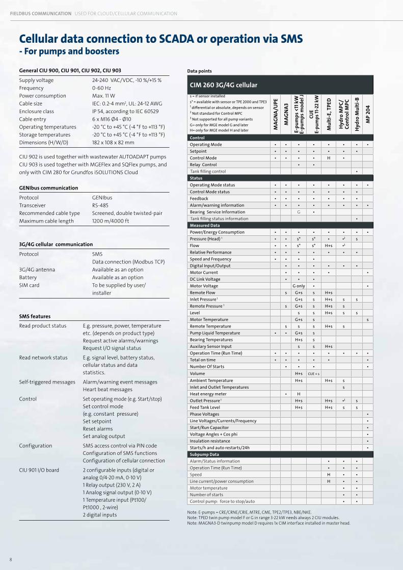
Cellular data connection to SCADA or operation via SMS- For pumps and boosters
General CIU 900, CIU 901, CIU 902, CIU 903
Supply voltage 24-240 VAC/VDC, -10 %/+15 %Frequency 0-60 HzPower consumption Max. 11 WCable size IEC: 0.2-4 mm2, UL: 24-12 AWGEnclosure class IP 54, according to IEC 60529Cable entry 6 x M16 Ø4 - Ø10Operating temperatures -20 °C to +45 °C (-4 °F to +113 °F)Storage temperatures -20 °C to +45 °C (-4 °F to +113 °F)Dimensions (H/W/D) 182 x 108 x 82 mm CIU 902 is used together with wastewater AUTOADAPT pumps CIU 903 is used together with MGEFlex and SQFlex pumps, and only with CIM 280 for Grundfos iSOLUTIONS Cloud GENIbus communication
Protocol GENIbusTransceiver RS-485 Recommended cable type Screened, double twisted-pairMaximum cable length 1200 m/4000 ft
3G/4G cellular communication
Protocol SMS Data connection (Modbus TCP)3G/4G antenna Available as an optionBattery Available as an optionSIM card To be supplied by user/ installer
SMS features
Read product status E.g. pressure, power, temperature etc. (depends on product type) Request active alarms/warnings Request I/O signal status
Read network status E.g. signal level, battery status, cellular status and data statistics.
Self-triggered messages Alarm/warning event messages Heart beat messages
Control Set operating mode (e.g. Start/stop) Set control mode (e.g. constant pressure) Set setpoint Reset alarms Set analog output
Configuration SMS access control via PIN code Configuration of SMS functions Configuration of cellular connection
CIU 901 I/O board 2 configurable inputs (digital or analog 0/4-20 mA, 0-10 V) 1 Relay output (230 V, 2 A) 1 Analog signal output (0-10 V) 1 Temperature input (Pt100/ Pt1000 , 2-wire) 2 digital inputs
Data points
CIM 260 3G/4G cellulars = if sensor installeds* = available with sensor or TPE 2000 and TPE31 differential or absolute, depends on sensor2 Not standard for Control MPC3 Not supported for all pump variants G= only for MGE model G and later H= only for MGE model H and later M
AGN
A/U
PE
MAG
NA
3
E-pu
mps
<11
kW
E-pu
mps
mod
el J
CUE
E-pu
mps
11-2
2 kW
Mul
ti-E
, TPE
D
Hyd
ro M
PC/
Cont
rol M
PC
Hyd
ro M
ulti
-B
MP
204
ControlOperating Mode • • • • • • • •Setpoint • • • • • • •Control Mode • • • • H •Relay Control • •Tank filling control •StatusOperating Mode status • • • • • • • •Control Mode status • • • • • • •Feedback • • • • • • •Alarm/warning information • • • • • • • •Bearing Service Information G •Tank filling status information •Measured DataPower/Energy Consumption • • • • • • • •Pressure (Head) 1 • • s* s* • •2 sFlow • • s* s* H+s •2
Relative Performance • • • • • • •Speed and Frequency • • • •Digital Input/Output • • • • • •Motor Current • • • • •DC Link Voltage • • •Motor Voltage G only • •Remote Flow s G+s s H+sInlet Pressure 1 G+s s H+s s sRemote Pressure 1 s G+s s H+s sLevel s s H+s s sMotor Temperature G+s s sRemote Temperature s s s H+s sPump Liquid Temperature • • G+s sBearing Temperatures H+s sAuxilary Sensor Input s s H+sOperation Time (Run Time) • • • • • • • •Total on time • • • • • •Number Of Starts • • • •Volume H+s CUE + s
Ambient Temperature H+s H+s sInlet and Outlet Temperatures sHeat energy meter • HOutlet Pressure 1 H+s H+s •2 sFeed Tank Level H+s H+s s sPhase Voltages •Line Voltages/Currents/Frequency •Start/Run Capacitor •Voltage Angles + Cos phi •Insulation resistance •Starts/h and auto restarts/24h •Subpump Data Alarm/Status information • • •Operation Time (Run Time) • • •Speed H • •Line current/power consumption H • •Motor temperature • •Number of starts • •Control pump: force to stop/auto • •
USED FOR CLOUD/CELLULAR COMMUNICATION IN WASTEWATER FIELDBUS COMMUNICATIONFIELDBUS COMMUNICATION USED FOR CLOUD/CELLULAR COMMUNICATION
Note: E-pumps = CRE/CRNE/CRIE, MTRE, CME, TPE2/TPE3, NBE/NKE. Note: TPED twin pump model F or G in range 3-22 kW needs always 2 CIU modules.Note: MAGNA3-D twinpump model D requires 1x CIM interface installed in master head.
9
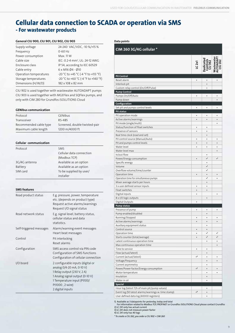
Cellular data connection to SCADA or operation via SMS- For pumps and boosters
Cellular data connection to SCADA or operation via SMS- For wastewater products
Data points
CIM 260 3G/4G cellular *
LC 2
x1
Ded
icat
ed
Cont
rols
CU
362
Was
tew
ater
AU
TOAD
APT
CIU
262
Pit ControlReset alarm • • •Interlock pit •Custom relay control (On/Off/Pulse) •Pump ControlPumps On/Off/Auto • • •Pump down •ConfigurationSet pit and pumps control levels • • •Pit statusPit operation mode • • •Active alarms/warnings • • •Pit mode (single/multi) •Status/function of float switches • •Presence of sensors • •Real time clock (read and set) •Pit control source (Manual/Auto) • • •Pit and pumps control levels • • •Water level • • •Water level max •In/out flow •Power/Energy consumption • •1 •1
Specific energy •Volume •1
Overflow volume/time/counter •1
Operation time • • •Operation time for simultaneous pumps •1 •Mixer average starts per hours •3 x user defined sensor inputs • •Float switches • •Digital inputs • •8 x I/O logic outputs •Digital Outputs •Pump statusPresence of pump • • •Pump enabled/disabled •Running/Stopped • • •Active alarms/warnings • • •Auxiliary equipment status •Control source • •Operation time • •1 •1
Starts counter (total/average) • •1 •1
Latest continuous operation time • •Max continuous operation time •Time to service • •Flow (actual/latest) •Current (actual/latest) •2 • •Voltage/frequency • •Current asymmetry •Power/Power factor/Energy consumption •3 • •Motor temperature • •Insulation •Water in oil •SpecialHour log (latest 72h of main pit/pump values) •Event log (50 latest alarms/warnings w. time stamp) •4 •User defined data log (40000 registers) •
1) Available as 3 datapoints for yesterday, today and total For information related to Modbus TCP, PROFINET or Grundfos iSOLUTIONS Cloud please contact Grundfos2) LC 2X1 only has actual current 3) LC 2X1 does not measure power factor 4) LC 2X1 only has 40 logs * To create a CIU 262, you order a CIU 902 + CIM 260
General CIU 900, CIU 901, CIU 902, CIU 903
Supply voltage 24-240 VAC/VDC, -10 %/+15 %Frequency 0-60 HzPower consumption Max. 11 WCable size IEC: 0.2-4 mm2, UL: 24-12 AWGEnclosure class IP 54, according to IEC 60529Cable entry 6 x M16 Ø4 - Ø10Operation temperatures -20 °C to +45 °C (-4 °F to +113 °F)Storage temperatures -20 °C to +60 °C (-4 °F to +140 °F)Dimensions (H/W/D) 182 x 108 x 82 mm CIU 902 is used together with wastewater AUTOADAPT pumps CIU 903 is used together with MGEFlex and SQFlex pumps, and only with CIM 280 for Grundfos iSOLUTIONS Cloud
GENIbus communication
Protocol GENIbusTransceiver RS-485 Recommended cable type Screened, double twisted-pairMaximum cable length 1200 m/4000 ft
Cellular communication
Protocol SMS Cellular data connection (Modbus TCP)3G/4G antenna Available as an optionBattery Available as an optionSIM card To be supplied by user/ installer
SMS features
Read product status E.g. pressure, power, temperature etc. (depends on product type) Request active alarms/warnings Request I/O signal status
Read network status E.g. signal level, battery status, cellular status and data statistics.
Self-triggered messages Alarm/warning event messages Heart beat messages
Control Pit interlocking Reset alarms
Configuration SMS access control via PIN code Configuration of SMS functions Configuration of cellular connection
I/O board 2 configurable inputs (digital or analog 0/4-20 mA, 0-10 V) 1 Relay output (230 V, 2 A) 1 Analog signal output (0-10 V) 1 Temperature input (Pt100/ Pt1000 , 2-wire) 2 digital inputs
USED FOR CLOUD/CELLULAR COMMUNICATION IN WASTEWATER FIELDBUS COMMUNICATION
10
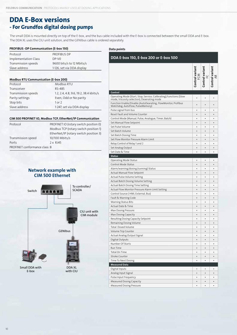
FIELDBUS COMMUNICATION PROTOCOLS MAINLY USED AT DOSING APPLICATIONS
Data points
DDA E-box 150, E-box 200 or E-box 500
Cont
rol v
aria
nt
FCM
Cont
rol v
aria
nt
FCCo
ntro
l var
iant
AR
ControlOperating Mode (Start, Stop, Service, Calibrating),Functions (Slow mode, Viscosity selection), Deaerating mode • • •
Function Enable/Disable (AutoDearating, FlowMonitor, Profibus Watchdog, AutoFlow, PulseMemory) • • •
Pulse signal from bus • • •Reset Fault and Volume Counter • • •Control Mode (Manual, Pulse, Analogue, Timer, Batch) • • •Set Manual Flow Setpoint • • •Set Pulse Volume • • •Set Batch Volume • • •Set Batch Dosing Time • • •Set Flow Monitor Pressure Alarm Limit • • •Relay Control of Relay 1 and 2 • • •Set Analog Output • • •Set Date & Time • • •StatusOperating Mode Status • • •Control Mode Status • • •Alarm/warning/dosing (running) Status • • •Actual Manual Flow Setpoint • • •Actual Pulse Volume Setting • • •Actual Batch Dosing Volume Setting • • •Actual Batch Dosing Time Setting • • •Actual Flow Monitor Pressure Alarm Limit Setting • • •Control Source ( HMI, External, Bus) • • •Fault & Warning Code • • •Warning Status Bits • • •Actual Date & Time • • •Max Dosing Pressure • • •Max Dosing Capacity • • •Resulting Dosing Capacity Setpoint • • •Remaining Dosing Volume • • •Total Dosed Volume • • •Volume Trip Counter • • •Actual Analog Output Signal • • •Digital Outputs • • •Number Of Starts • • •Run Time • • •Total On Time • • •Stroke Counter • • •Time To Next Dosing • • •Measured DataDigital Inputs • • •Analog Input Signal • • •Pulse Input Frequency • • •Measured Dosing Capacity • • •Measured Dosing Pressure • • •
DDA XL with CIU
Small DDA with E-box
DDA E-Box versions- For Grundfos digital dosing pumps
PROFIBUS -DP Communication (E-box 150)
Protocol PROFIBUS DPImplementation Class DP-V0Transmission speeds 9600 bits/s to 12 Mbits/sSlave address 1-126, set via DDA display Modbus RTU Communication (E-box 200)Protocol Modbus RTUTransceiver RS-485Transmission speeds 1.2, 2.4, 4.8, 9.6, 19.2, 38.4 kbits/s Parity settings Even, Odd or No parity Stop bits 1 or 2 Slave address 1-247, set via DDA display CIM 500 PROFINET IO, Modbus TCP, EtherNet/IP Communication
Protocol PROFINET IO (rotary switch position 0) Modbus TCP (rotary switch position 1) EtherNet/IP (rotary switch position 3) Transmission speed 10/100 Mbits/s Ports 2 x RJ45PROFINET conformance class B
GENIbus
CIU unit with CIM module
Network example with CIM 500 Ethernet
The small DDA is mounted directly on top of the E-box, and the bus cable included with the E-box is connected between the small DDA and E-box.The DDA XL uses the CIU unit solution, and the GENIbus cable is ordered separately.
To controller/SCADASwitch
11
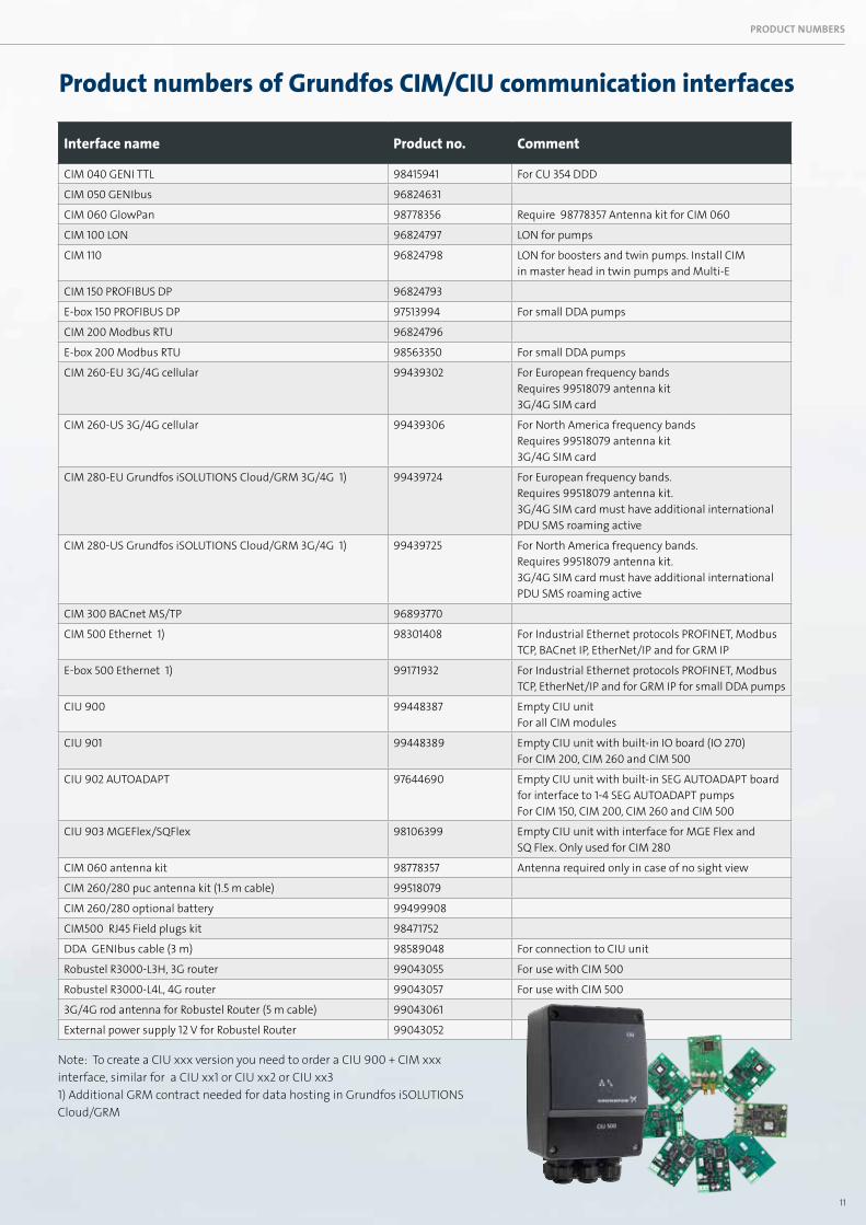
Interface name Product no. Comment
CIM 040 GENI TTL 98415941 For CU 354 DDD
CIM 050 GENIbus 96824631
CIM 060 GlowPan 98778356 Require 98778357 Antenna kit for CIM 060
CIM 100 LON 96824797 LON for pumps
CIM 110 96824798 LON for boosters and twin pumps. Install CIM in master head in twin pumps and Multi-E
CIM 150 PROFIBUS DP 96824793
E-box 150 PROFIBUS DP 97513994 For small DDA pumps
CIM 200 Modbus RTU 96824796
E-box 200 Modbus RTU 98563350 For small DDA pumps
CIM 260-EU 3G/4G cellular 99439302 For European frequency bandsRequires 99518079 antenna kit 3G/4G SIM card
CIM 260-US 3G/4G cellular 99439306 For North America frequency bandsRequires 99518079 antenna kit 3G/4G SIM card
CIM 280-EU Grundfos iSOLUTIONS Cloud/GRM 3G/4G 1) 99439724 For European frequency bands.Requires 99518079 antenna kit.3G/4G SIM card must have additional international PDU SMS roaming active
CIM 280-US Grundfos iSOLUTIONS Cloud/GRM 3G/4G 1) 99439725 For North America frequency bands.Requires 99518079 antenna kit.3G/4G SIM card must have additional international PDU SMS roaming active
CIM 300 BACnet MS/TP 96893770
CIM 500 Ethernet 1) 98301408 For Industrial Ethernet protocols PROFINET, Modbus TCP, BACnet IP, EtherNet/IP and for GRM IP
E-box 500 Ethernet 1) 99171932 For Industrial Ethernet protocols PROFINET, Modbus TCP, EtherNet/IP and for GRM IP for small DDA pumps
CIU 900 99448387 Empty CIU unitFor all CIM modules
CIU 901 99448389 Empty CIU unit with built-in IO board (IO 270)For CIM 200, CIM 260 and CIM 500
CIU 902 AUTOADAPT 97644690 Empty CIU unit with built-in SEG AUTOADAPT board for interface to 1-4 SEG AUTOADAPT pumpsFor CIM 150, CIM 200, CIM 260 and CIM 500
CIU 903 MGEFlex/SQFlex 98106399 Empty CIU unit with interface for MGE Flex and SQ Flex. Only used for CIM 280
CIM 060 antenna kit 98778357 Antenna required only in case of no sight view
CIM 260/280 puc antenna kit (1.5 m cable) 99518079
CIM 260/280 optional battery 99499908
CIM500 RJ45 Field plugs kit 98471752
DDA GENIbus cable (3 m) 98589048 For connection to CIU unit
Robustel R3000-L3H, 3G router 99043055 For use with CIM 500
Robustel R3000-L4L, 4G router 99043057 For use with CIM 500
3G/4G rod antenna for Robustel Router (5 m cable) 99043061
External power supply 12 V for Robustel Router 99043052
Note: To create a CIU xxx version you need to order a CIU 900 + CIM xxx interface, similar for a CIU xx1 or CIU xx2 or CIU xx3 1) Additional GRM contract needed for data hosting in Grundfos iSOLUTIONS Cloud/GRM
PRODUCT NUMBERS
Product numbers of Grundfos CIM/CIU communication interfaces
GRUNDFOS Holding A/SPoul Due Jensens Vej 7DK-8850 BjerringbroTel: +45 87 50 14 00www.grundfos.com
The
nam
e G
rund
fos,
the
Gru
ndfo
s log
o, a
nd b
e th
ink
inno
vate
are
regi
ster
ed tr
adem
arks
ow
ned
by G
rund
fos H
oldi
ng A
/S o
r Gru
ndfo
s A/S
, Den
mar
k. A
ll rig
hts r
eser
ved
wor
ldw
ide.
Advantages of Grundfos CIM/CIU communication interfaces• Enables connection of any Grundfos pump or controller to a BMS/SCADA
system • Pumps and controller have better reliability with reduced downtime, due to
monitoring and control functionality on a BMS/SCADA system • The operational cost of pumps can be lowered by reducing setpoints to match
precise system needs via remote control • Remote monitoring and control via BMS/SCADA systems reduce manual
settings, monitoring time and travel time to sites or installations. • Enable predictive maintenance and fast reaction time on process changes
and exceptions • Simple configuration of Fieldbus settings saves commissioning time • Modular design – prepared for future needs • Wide range 24-240 VAC/VDC power supply in CIU • Easy to install, as Grundfos delivers the required support files and functional
profile manuals
About GrundfosGrundfos is one of the world’s leading pump manufacturers and has been renowned for its innovative and reliable solutions since 1945. Today, we produce more than 16 million pump units every year for a wide range of application areas. Grundfos iSOLUTIONS brings a new era of intelligence to pump systems and water technology with solutions that look beyond individual components and optimise the entire system.
Learn more at www.grundfos.com/isolutions99
6227
41/0
819/
IND
UST
RY/4
0111
64-B
rand
Box