Embed Size (px)
Citation preview
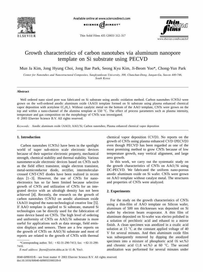
Thin Solid Films 435(2003) 312–317
0040-6090/03/$ - see front matter� 2003 Elsevier Science B.V. All rights reserved.doi:10.1016/S0040-6090Ž03.00339-0
Growth characteristics of carbon nanotubes via aluminum nanoporetemplate on Si substrate using PECVD
Mun Ja Kim, Jong Hyung Choi, Jong Bae Park, Seong Kyu Kim, Ji-Beom Yoo*, Chong-Yun Park
Center for Nanotubes and Nanostructured Composites, Sungkyunkwan University, 300, Chunchun-Dong, Jangan-Gu, Suwon 440-746,South Korea
Abstract
Well ordered nano sized pore was fabricated on Si substrate using anodic oxidation method. Carbon nanotubes(CNTs) weregrown on the well-ordered anodic aluminum oxide(AAO) template formed on Si substrate using plasma enhanced chemicalvapor deposition with acetylene(C H ). Without catalytic metal on the bottom of the AAO template, CNTs were grown on the2 2
top and within a nano-channel of the alumina template at 5508C. The effect of process parameters such as plasma intensity,temperature and gas composition on the morphology of CNTs was investigated.� 2003 Elsevier Science B.V. All rights reserved.
Keywords: Anodic aluminum oxide(AAO); AAOySi; Carbon nanotubes; Plasma enhanced chemical vapor deposition
1. Introduction
Carbon nanotubes(CNTs) have been in the spotlightworld of super sub-micro scale electronic devicesbecause of their superior electronic property, mechanicalstrength, chemical stability and thermal stability. Variousnanometer-scale electronic devices based on CNTs suchas the field effect transistor, single electron transistor,metal-semiconductor diode, rectifier, intermolecular-crossed CNT-CNT diodes have been realized in recentdays w1–3x. However, the use of CNTs for nano-electronics has so far been limited because selectivegrowth of CNTs and utilization of CNTs for an inte-grated device with an ultrahigh density has not beenachievedw4x. Recently, the research on the growth ofcarbon nanotubes(CNTs) on anodic aluminum oxide(AAO) inspired the nano-technological creative linew5x.If AAO template is applied to Si substrate, matured Sitechnologies can be directly used for the fabrication ofnano device based on CNTs. The high level of orderingand uniformity of CNTs on AAOySi substrate is moreuseful for applications such as data storage, field emis-sion displays and sensors. There are a few reports onthe growth of CNTs on AAOySi substrate and most ofreports are related to the growth of CNTs with thermal
*Corresponding author. Tel.:q82-31-290-7413; fax:q82-31-290-7410.
E-mail address: [email protected](J.-B. Yoo).
chemical vapor deposition(CVD). No reports on thegrowth of CNTs using plasma enhanced CVD(PECVD)even though PECVD has been regarded as one of themost promising method to grow CNTs because of lowtemperature growth, easy vertical alignment, and largearea growth.In this work, we carry out the systematic study on
the growth characteristics of CNTs on AAOySi usingDC-PECVD. We fabricated the uniform nano-porousanodic aluminum oxide on Si wafer. CNTs were grownon AAO template without catalyst metal. The structuresand properties of CNTs were analyzed.
2. Experiments
For the study on the growth characteristics of CNTsusing a thin-film of AAO template on Silicon wafer,aluminum of 500 nm thicknesses was deposited on Siwafer by electron beam evaporator. A thin film ofaluminum deposited on Si-wafer was electro polished ina solution of perchloric acid and ethanol to a mirrorfinish. A clean specimen was anodized in a oxalic acidsolution at 158C at the constant applied voltage of 40V for several minutes. And then aluminum oxide filmwas subsequently removed by dipping the anodizedspecimen into a mixture of phosphoric acid(6 wt.%)and chromic acid(1.8 wt.%) at 60 8C. The secondanodization was performed for several minutes under

313M.J. Kim et al. / Thin Solid Films 435 (2003) 312–317
Fig. 1. (a) The schematic diagram of anodic aluminum oxide template on silicon substrate.(b) FE SEM images of an anodic aluminum oxide(AAO) formed on silicon substrate.
the same condition as the first one. The pore depth wasapproximately 200 nm(200 nm"15%). The pore ofthe template was widened by immersing in an aqueousphosphoric acid solution for 30 min.The CNTs growth was carried out on the AAO
template below 5508C by PECVD. An acetylene(C H ) gas was used as a carbon source and an ammonia2 2
(NH ) gas was used as a dilution and catalytic gas. The3
dc plasma was used to grow vertically aligned CNTs.The anodized substrate was transferred to the reactionchamber. Reactor was pumped down below 2=10y5
Torr by a rotary and a diffusion pump. And subsequently,NH was injected into the chamber. After the working3
pressure of 3 Torr, had been stabilized, Infra-Red(IR)lamp was turned on and adjusted to 5508C, and thenthe dc power supply began to work. The pre-treatmentof the substrate for surface activation was conducted bythe NH plasma for 5 min. C H flowed into the chamber3 2 2
for the growth of CNTs for 15 min. A pressure duringthe CNTs growth was maintained to be at 3 to 4 Torr.For the analysis of the morphology, the microstructureand crystalline of AAO and CNTs, field emission scan-ning electron microscope(FE-SEM), high-resolutiontransmission electron microscope(HR-TEM), atomic
force microscopy(AFM), Raman spectroscopy and X-ray diffraction(XRD) were employed.
3. Results and discussion
The schematics and FE-SEM images of the fabricatedanodic aluminum oxide on Si substrates are shown inFig. 1. For Al layer on the Si substrate the ideallyordered nanopore configuration was usually obtainedusing the two-step anodization. The first anodizationwas usually carried out for several minutes. The elimi-nation of the anodic oxide film generated the orderedarray of dimples on the Al surface. The development ofan ordered array of holes was formed during the secondanodization. For the 1st oxidation of the Al layer, theearlier current density was approximately 1.3 mAycm2
at 40 V. As the oxidation proceeded, the color of thespecimen surface changed. And then, the second oxi-dation was carried out under the same condition as the1st anodization of specimen. The pore diameters wereenlarged by the subsequent pore widening operation inwhich the AAO template was immersed into a 0.1 Mphosphoric acid at 25–358C for 10–40 min.

314 M.J. Kim et al. / Thin Solid Films 435 (2003) 312–317
Fig. 2. Field enhanced-scanning electro microscope(FE-SEM) image of the CNTs grown at 5508C for 15 min using PECVD.(a) cross viewand(b) top view of CNTs grown on AAOySi using PECVD.
The pore diameter was approximately 27(27nm"10%) and 60 nm(60 nm"15%) after the secondanodization and pore widening, respectively. Comparingthe FE-SEM image(Fig. 1b) with the schematics(Fig.1a), fabricated nano-pore template was relatively disor-dered. The disordered pore arrangements depend on theanodic voltage, the electrolyte, and its concentration.And it was reported that the anodic voltage has a majoreffect on both pore diameter and the inter-pore distanceincreases linearly with voltagew6,7x. The disordered
patterning of AAO template shown in Fig. 1b was dueto the short the first oxidation time because the depositedAl film was so thin. For the application to CNTs growth,the barrier layer formed at the bottom of the pore on Sisubstrate should be eliminated. We performed overetch-ing the AAOySi, resulting in the elimination of barrierlayer as shown in Fig. 1b.CNTs was grown at 5508C for 15 min with 20%
C H and 80% NH . CNTs were vertically grown on2 2 3
the AAOySi substrate as shown in Fig. 2. The average

315M.J. Kim et al. / Thin Solid Films 435 (2003) 312–317
Fig. 3. High Resolution-Transmission Electron Microscope(HR-TEM) image of the CNTs grown at 5508C for 15 min using PECVD.(a) ‘A’ in Fig. 2a and (b) ‘B’ in Fig. 2a.
Fig. 5. Variation of morphology of CNTs with C H flow rate.(a) 202 2
sccm,(b) 15 sccm, and(c) 10 sccm.
Fig. 4. Raman spectroscopy of the CNTs grown on AAOySi substrate.

316 M.J. Kim et al. / Thin Solid Films 435 (2003) 312–317
Fig. 6. Field emission-scanning electron microscope(FE-SEM) imag-es of CNTs with the C HyNH flow ratio variations.(a) C H yNH s2 2 3 2 2 3
1:3, (b) C H yNH s1:4, (c) C H yNH s1:5.2 2 3 2 2 3
diameter and the length of CNTs grown on AAOySisubstrate was approximately 30(30 nm"15%) and 270nm (270 nm"10%), respectively. CNTs were grown onthe barrier of AAOySi cell–part. The grown CNTs onthe barrier between pores did not look like a nano-tubebut as a carbon nanofiber. Shape and structure of theCNTs were significantly affected by the growth condi-tion. The CNT growth on AAOySi was not optimizedand seemed to be quite different from the CNT growthon the planar substrate with catalytic layer. BesidesCNTs on the barrier, carbon layer seemed to form in thenano-pore.Because, in the previous study, most of the CNTs on
AAO grew vertically with respect to the surface of AAOfilm at 550 8C or higher temperature, using thermalCVD although a few CNTs appeared slightly tangled orcurved. In the case of 5008C, most CNTs gather togetherand form lump w8x. Also, most of the CNTs growvertically and clearly as well at 5508C, using plasmaenhanced chemical vapor deposition(PECVD).
The microstructure of CNTs on AAOySi substrateand carbon deposited in the nano pores were investigatedusing the high resolution-transmission electron micro-scope(HR-TEM). The HR-TEM image in Fig. 3a wastaken from the CNTs grown on the barrier(marked as‘A’ in Fig. 2a). The multi-layered carbon crystallinewith central hollow suggests that the CNTs are formedon the AAOySi substrate instead of carbon nanofiber.Graphization of the CNTs was very poor compared tothat of CNTs grown on glass substrate using PECVD.It implies that the growth condition for CNTs on AAOySi was not optimized and needs further investigation.Fig. 3b was taken at the area marked ‘B’ in Fig. 2a.Fig. 3b shows the deposited carbon layer, which lookslike a carbon anion patterns.Fig. 4 shows the Raman spectrum of CNTs on AAOy
Si substrate. Raman spectra were obtained using theargon laser excitation wavelength of 514.5 nm(Renis-haw-3000). Two peaks were observed at approximately1345.5 cm and 1606 cm . The peak at 1606 cmy1 y1 y1
corresponds to theE longitudinal optic(LO) compo-2g
nent of the G mode in graphite at 1582 cm , while they1
peak at approximately 1345.5 cm(D line) was attrib-y1
uted to disorders that were caused by the low tempera-ture PECVD process in our system. A strong intensityat approximately 1596 cm (G line) was usuallyy1
interpreted as a peak from highly oriented pyrolyticgraphite. However, in this study we did not get a strongpeak at approximately 1596 cm (G line). GyDy1
(GraphiteyDefect) ratio of the CNTs, we obtained fromCNTs on AAOySi was 1.028, indicating poor crystallinequality, which agrees well with the FR-TEM image asshown in Fig. 3.As shown in Fig. 2, the C H flow rate of 20 sccm2 2
seemed to supply more carbon source than required forthe nanotube growth. Reduced amount of carbon source
317M.J. Kim et al. / Thin Solid Films 435 (2003) 312–317
was tested and the effect of C H flow rate on the2 2
morphology of CNTs was investigated. Fig. 5a, b and care the FESEM image of CNTs grown with C H flow2 2
rate of 20, 15 and 10 sccm, respectively. As mentionedin the experimental part, C HyNH flow rate ratio in2 2 3
all samples was 4. As shown in the Fig. 5, the CNTsgrowth decreased as C H flow rate decreased. However,2 2
growth on the barrier as well as deposit within thenanopore were still observed, indicating that furtherreduction in the carbon supply is required.It is reported that the C HyNH flow rate ratio2 2 3
played an important role in the CNTs growth. Theetching effect of NH on the growth of CNTs was tested3
and shown in Fig. 6. C H flow rate in all samples was2 2
20 sccm. CNTs, shown in Fig. 6a, b and c were grownon AAOySi substrate with NH to C H flow rate ratio3 2 2
of 3, 4 and 5, respectively. As the NH flow rate3
increased, CNTs grown on the upper-part of AAOySiremained, but the size of CNTs increased with a reduc-tion of CNT density, which was not remarkable. It maybe due to the over supply of C H . The etching effect2 2
of NH was negligible under these conditions.3
4. Conclusions
AAO template with pore diameter of 60 nm wasformed on Si substrate through the electro polishing,two steps anodization, and pore widening. Irregularityin the cell configuration was attributed to the shortperiod of the first and second anodization process. CNTs
were grown on AAOySi substrate using PECVD. HR-TEM shows the formation of grapheme layer with acentral hollow on the top of AAO template and carbonanion deposit within nanopores. Raman spectra revealedpoor crystal quality of grown CNTs. As the flow rate ofC H decreased, growth of CNTs reduced. NH to2 2 3
C H flow rate ratio did not have an effect on the2 2
morphology of CNTs.
Acknowledgments
This work was supported by KOSEF through CNNC.
References
w1x S.J. Tans, A.R.M. Verschueren, C. Dekker, Nature 393(1998)49, (London).
w2x R. Martel, T. Schmidt, H.R. Shea, T. Hertel, P. Avouris, Appl.Phys. Lett. 73(1998) 2447.
w3x J.T. Hu, O.Y. Min, P.D. Yang, C.M. Lieber, Nature 399(1999)48, (London).
w4x W.-B. Choi, J.-U. Chu, K.-S. Jeong, E.-J. Bae, J.-W. Lee, J.-J.Kim, J.-O. Lee, Appl. Phys. Lett. 79(2001) 22.
w5x S.-H. Jeong, H.-Y. Hwang, K.-H. Lee, Appl. Phys. Lett. 78(2001) 14.
w6x K. Ebihara, H. Takahashi, M. Nagayama, J. Met. Finish. Soc.Jpn. 34(1983) 548.
w7x A.P. Li, F. Muller, A. Birner, K. Nielsch, U. Gosele, J. Appl.Phys. 84(1998) 11.
w8x Jin Seung Lee. Fabrication of carbon nanotubes was usingAAO templates and their applications. Ph.D. Thesis, 2001, p.69.