Embed Size (px)
Citation preview
1Ittsatotttotumwmipht
stm3capIgicaa
572 J. Opt. Soc. Am. A/Vol. 23, No. 3 /March 2006 B. Bai and L. Li
Group-theoretic approach to enhancing theFourier modal method
for crossed gratings with square symmetry
Benfeng Bai and Lifeng Li
State Key Laboratory of Precision Measurement Technology and Instruments, Department of Precision Instruments,Tsinghua University, Beijing 100084, China
Received July 6, 2005; accepted July 26, 2005
The Fourier modal method for crossed gratings with square symmetry is reformulated by use of a group-theoretic approach that we developed recently. In the new formulation, a crossed-grating problem is decom-posed into six symmetrical basis problems whose field distributions are the symmetry modes of the grating.Then the symmetrical basis problems are solved with symmetry simplifications, whose solutions are super-posed to get the solution of the original problem. Theoretical and numerical results show that when the gratingis at some Littrow mountings, the computation efficiency can be improved effectively: The memory occupationis reduced by 3/4 and the computation time is reduced by a factor from 25.6 to 64 in different incident cases.Numerical examples are given to show the effectiveness of the new formulation. © 2006 Optical Society ofAmerica
OCIS codes: 050.1950, 050.2770, 260.2110.
tOtpm
2AFsabaswttt
fatbROt
3Apsc
. INTRODUCTIONn the development of crossed-grating theory, improvinghe computation efficiency of numerical methods is one ofhe most imperative tasks because all methods to date aretill too time-consuming and memory hungry to meet thepplication demands. Recently we developed a group-heoretic approach1 that utilizes the structural symmetryf crossed gratings to speed up the computation. Unlikehe previously used intuitive method,2–5 the group-heoretic approach deals with all symmetry cases in a sys-ematical way and it can find all incident mountings (notnly normal incidence) in which improving the computa-ion by use of symmetry is possible. As an application, wese this approach to reformulate the Fourier modalethod6–8 (FMM, also known as the rigorous coupled-ave approach), which is one of the most versatile nu-erical methods for solving diffraction problems of grat-
ngs. According to crystallography,9 all plane periodicatterns of crossed gratings belong to 17 plane groups;ence the reformulation can be carried out for each ofhem.
In previous publications10–12 we have treated someimple symmetry cases in which the symmetry modes ofhe grating are all nondegenerate (the meanings of sym-etry modes and degeneracy will be explained in Section
). In this paper we take up a more complex symmetryase of plane group p4mm, in which the doubly degener-te symmetry modes are involved. A representative planeeriodic pattern of plane group p4mm is shown in Fig. 1.t is in square lattice and has the symmetry of pointroup C4� that consists of eight symmetry operations: thedentity operation e that leaves the pattern unchanged;2, c4
1, and c43 that rotate the pattern counterclockwise
bout the normal (the z axis) of the pattern plane throughngles �, � /2, and 3� /2, respectively; � , � , � , and �
x y a b1084-7529/06/030572-9/$15.00 © 2
hat apply reflections to the pattern across axes Ox, Oy,a, and Ob, respectively. Since these operations are all
hose possessed by a square, for simplicity the gratings oflane group p4mm are also said to be with square sym-etry in what follows.
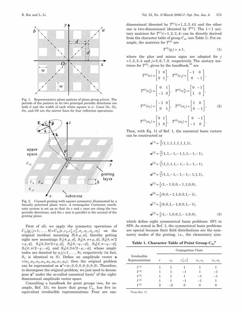
. STATEMENT OF THE PROBLEMcrossed grating with square symmetry is depicted in
ig. 2, where the grating layer is a slab embedded withquare cross-section pillars and its top view is the sames that in Fig. 1. The whole physical space is assumed toe isotropic and nonmagnetic (i.e., the permeability �=1)nd is divided into three parts: The upper space and theubstrate are homogeneous semi-infinite subspaces,hose permittivities are denoted by �+1 and �−1, respec-
ively; the grating layer has a thickness h and its permit-ivity ��x ,y� is a piecewise-constant, z-independent func-ion taking two values �a and �b.
A plane wave of amplitude a impinges on the gratingrom the upper space with a polar angle �, an azimuthalngle �, and a polarization angle �. The unit vector p is inhe plane of incidence and s is perpendicular to it, botheing orthogonal to the incident k vector. According toef. 1, such an incident mounting is denoted by S�� ,� ,��.bviously, in general it does not possess the same symme-
ry as the grating structure.
. PROBLEM DECOMPOSITIONccording to the group-theoretic approach, a generalroblem defined above should be first decomposed into auperposition of several symmetrical basis problems. Thisan be achieved by following the steps given in Ref. 1.
006 Optical Society of America
Coe+StS=ctpd
ae
dotfa
w=t
Tc
wSam
FpbO
Flnpg
B. Bai and L. Li Vol. 23, No. 3 /March 2006/J. Opt. Soc. Am. A 573
First of all, we apply the symmetry operations of4��gj � j=1, . . . , 8�=C4��e ,c2 ,c4
1 ,c43 ,�x ,�y ,�a ,�b� on the
riginal incident mounting S�� ,� ,��, thereby gettingight new mountings S1�� ,� ,��, S2�� ,�+� ,��, S3�� ,� /2� ,��, S4�� ,3� /2+� ,��, S5�� ,−� ,−��, S6�� ,�−� ,−��,7�� ,� /2−� ,−��, and S8�� ,3� /2−� ,−��, whose ampli-
udes are denoted by aj�j=1, . . . , 8�, respectively (in fact,1 is identical to S). Define an amplitude vector a�a1 ,a2 ,a3 ,a4 ,a5 ,a6 ,a7 ,a8�; then the original probleman be represented as a0= �a ,0 ,0 ,0,0,0,0,0�. Therefore,o decompose the original problem, we just need to decom-ose a0 under the so-called canonical basis1 of the eight-imensional amplitude vector space.Consulting a handbook for point groups (see, for ex-
mple, Ref. 13), we know that group C4� has five in-quivalent irreducible representations: Four are one-
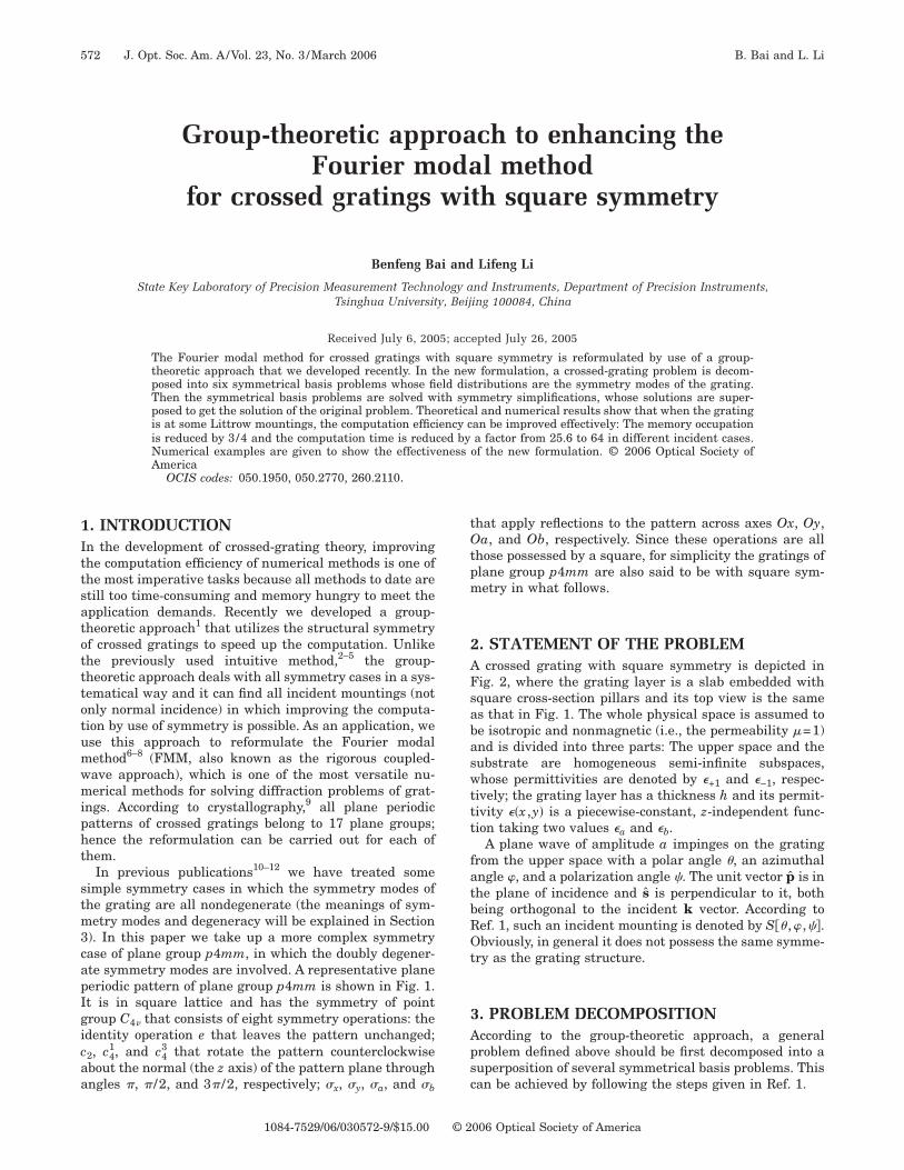
ig. 1. Representative plane pattern of plane group p4mm. Theeriods of the pattern in its two principal periodic directions areoth d and the width of each white square is w. Lines Ox, Oy,a, and Ob are the mirror lines for four reflection operations.
ig. 2. Crossed grating with square symmetry illuminated by ainearly polarized plane wave. A rectangular Cartesian coordi-ate system is set up so that its x and y axes are along the twoeriodic directions, and the z axis is parallel to the normal of therating plane.
imensional [denoted by T�i��i=1,2,3,4�] and the otherne is two-dimensional [denoted by T�5�]. The 11 uni-ary matrices for T�i��i=1,2,3,4� can be directly derivedrom the character table of group C4� (see Table 1). For ex-mple, the matrices for T�3� are
T�3��gj� = ± 1, �1�
here the plus and minus signs are adopted for j1,2,3,4 and j=5,6,7,8, respectively. The unitary ma-
rices for T�5�, given by the handbook,13 are
T�5��e� = �1 0
0 1, T�5��c2� = �− 1 0
0 − 1 ,
T�5��c41� = � 0 1
− 1 0, T�5��c43� = �0 − 1
1 0 ,
T�5���x� = �− 1 0
0 1, T�5���y� = �1 0
0 − 1 , �2�
T�5���a� = �0 1
1 0, T�5���b� = � 0 − 1
− 1 0 .
hen, with Eq. 11 of Ref. 1, the canonical basis vectorsan be constructed as
a�1� =24 �1,1,1,1,1,1,1,1�,
a�2� =24 �1,1,− 1,− 1,1,1,− 1,− 1�,
a�3� =24 �1,1,1,1,− 1,− 1,− 1,− 1�,
a�4� =24 �1,1,− 1,− 1,− 1,− 1,1,1�,
a�5� = 12 �1,− 1,0,0,− 1,1,0,0�,
a�6� = 12 �0,0,− 1,1,0,0,1,− 1�,
a�7� = 12 �0,0,1,− 1,0,0,1,− 1�,
a�8� = 12 �1,− 1,0,0,1,− 1,0,0�, �3�
hich define eight symmetrical basis problems: SP1 toP8. As stated in Ref. 1, the symmetrical basis problemsre special because their field distributions are the sym-etry modes of the grating, i.e., the elementary sym-
Table 1. Character Table of Point Group C4�a
IrreducibleRepresentation
Conjugation Class
e c2 c41 ,c4
3 �x ,�y �a ,�b
�1� 1 1 1 1 1�2� 1 1 −1 1 −1�3� 1 1 1 −1 −1�4� 1 1 −1 −1 1�5� 2 −2 0 0 0
aFrom Ref. 13.
mstoiotemartwt
ib
Iii
ttpmbd
wtcfpn
Ner
Eft
s
a
E
E
E
wfim
meohmEvpmm8es
lttis
snShw(dtw
4MASs
574 J. Opt. Soc. Am. A/Vol. 23, No. 3 /March 2006 B. Bai and L. Li
etrical field distributions for a given grating. Any fieldatisfying Maxwell’s equations and the boundary condi-ions imposed by the grating is certainly a superpositionf these modes. The symmetry modes are further dividednto two kinds. Since a�j� �j=1, . . . , 4� are derived from thene-dimensional irreducible representations, the symme-ry modes of SP1 to SP4 are nondegenerate, meaning thatach of them does not couple with the other modes in sym-etry transformations. However, the modes of SP5 to SP8
re doubly degenerated because a�j� �j=5, . . . , 8� are de-ived from the two-dimensional irreducible representa-ion T�5�. Namely, the fields of SP5 and SP7 would coupleith those of SP6 and SP8, respectively, in symmetry
ransformations.Now we can decompose the field of the original problem
nto a linear combination of the fields of the symmetricalasis problems according to Eqs. 14 and 15 of Ref. 1:
E0�r� =24 a�
j=1
4
E�j��r� + 12a�E�5��r� + E�8��r��. �4�
n Eq. (4) the fields of SP6 and SP7 do not appear, mean-ng that the two symmetry modes are not excited by thencident condition that we defined in Section 2.
To solve the symmetrical basis problems with symme-ry simplifications, we should also get the symmetry rela-ions of the field in each symmetry mode. For this pur-ose, we first derive, according to Eq. 13 of Ref. 1, theatrix representation of group C4� under the canonical
asis (i.e., the canonical matrices in diagonal or block-iagonal form):
T = T�1�� T�2�
� T�3�� T�4�
� T�5�� T�5�, �5�
here the dependence of T and T�i� on gj is omitted. Thenhe matrix representation of group C4� in the rectangularoordinate system, which describes the symmetry trans-ormations of position vectors r and field vectors u in thehysical space, is also needed. By considering the coordi-ate transforms, we can easily write out these matrices as
M�e� = I, M�c2� = − 1 � − 1 � 1,
M�c41� = �0 − 1
1 0 � 1, M�c43� = � 0 1
− 1 0 � 1,
M��x� = 1 � − 1 � 1, M��y� = − 1 � 1 � 1,
M��a� = �0 1
1 0 � 1, M��b� = � 0 − 1
− 1 0 � 1. �6�
ow with Eq. 9 of Ref. 1, the symmetry relations of thelectric field in eight symmetrical basis problems are de-ived as
M�gn�E�i��M�gn�−1r� = �j=1
8
Tji�gn�E�j��r� �i,n = 1, . . . , 8�.
�7�
quation (7) is of great importance to us because the re-ormulation of the FMM is squarely based on it. Accordingo Eq. (7), the symmetry relations in a nondegenerate
ymmetry mode, say SP3, are
Ex�3��x,y� = − Ex
�3��− x,− y� = − Ey�3��y,− x� = Ey
�3��− y,x�
= − Ex�3��x,− y� = Ex
�3��− x,y� = − Ey�3��y,x�
= Ey�3��− y,− x�,
Ey�3��x,y� = − Ey
�3��− x,− y� = Ex�3��y,− x� = − Ex
�3��− y,x�
= Ey�3��x,− y� = − Ey
�3��− x,y� = − Ex�3��y,x�
= Ex�3��− y,− x�; �8�
nd in a degenerate symmetry mode, say SP8, we have
x�8��x,y� = Ex
�8��− x,− y� = Ex�8��x,− y� = Ex
�8��− x,y�,
y�8��x,y� = Ey
�8��− x,− y� = − Ey�8��x,− y� = − Ey
�8��− x,y�, �9a�
x�7��x,y� = Ey
�8��y,x�, Ey�7��x,y� = Ex
�8��y,x�, �9b�
here the common dependence of E��i� on z is omitted. The
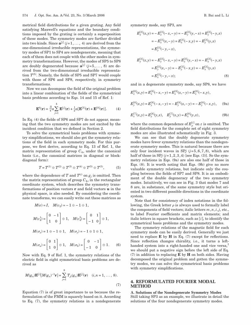
eld distributions for the complete set of eight symmetryodes are also illustrated schematically in Fig. 3.We can see that the doubly degenerate symmetryodes have fewer symmetry relations than the nondegen-
rate symmetry modes. This is natural because there arenly four incident waves in SPj �j=5,6,7,8�, which arealf of those in SPj �j=1,2,3,4� [see Eqs. (3)]. So the sym-etry relations in Eqs. (9a) are also one half of those inqs. (8). It is worth noting that Eqs. (9b) give no morealuable symmetry relations, but indicate only the cou-ling between the fields of SP7 and SP8. It is an embodi-ent of the double degeneracy of the two symmetryodes. Intuitively, we can see in Fig. 3 that modes 7 andare, in substance, of the same symmetry style but ori-
nted in two different possible directions in the coordinateystem.
Note that for consistency of index notations in the fol-owing, the Greek letter � is always used to formally labelhe components of field vectors; italic letters m ,n , i , j, etc.,o label Fourier coefficients and matrix elements; andtalic letters in square brackets, such as �i�, to identify theymmetrical basis problems and the symmetry modes.
The symmetry relations of the magnetic field for eachymmetry mode can be easily derived. Generally we justeed to replace E by H in Eq. (7) except for reflections.ince reflection changes chirality, i.e., it turns a left-anded system into a right-handed one and vice versa,1
e should put a negative sign before the left side of Eq.7) in addition to replacing E by H on both sides. Havingecomposed the original problem and gotten the symme-ry modes, we can solve the symmetrical basis problemsith symmetry simplifications.
. REFORMULATED FOURIER MODALETHOD
. Solutions of the Nondegenerate Symmetry Modestill taking SP3 as an example, we illustrate in detail theolutions of the four nondegenerate symmetry modes.
1IewlFa
w�m==bcb
2Iofcwonldt�Tnic
F
FcmOts
Ft1dop[tcd
B. Bai and L. Li Vol. 23, No. 3 /March 2006/J. Opt. Soc. Am. A 575
. Fourier Expansion of the Fieldn SP3 the incident amplitude vector is a�3�= �2/4��1,1,1,1,−1,−1,−1,−1� which means that there are
ight incident plane waves at mountings Sj �j=1, . . . ,8�ith amplitudes 2/4 (the first four waves) or −2/4 (the
ast four waves). So in the periodic region, the Floquet–ourier expansions of the total electric field componentsre
E��3��r� = �
m,n�E�mn
�3,1��z�exp�i��mx + ny�� + E��−m��−n��3,2� �z�
exp�i�− �mx − ny�� + E��−n�m�3,3� �z�
exp�i�− nx + �my�� + E�n�−m��3,4� �z�
exp�i� nx − �my�� + E�m�−n��3,5� �z�
exp�i��mx − ny�� + E��−m�n�3,6� �z�
exp�i�− �mx + ny�� + E�nm�3,7��z�
ig. 3. Schematic illustration of the eight symmetry modes of arossed grating with square symmetry. In each mode, the sym-etrical distribution of the electric vectors projected onto thexy plane is shown by arrows. The solid (open) arrows indicate
he vectors with the same z components, which have the oppositeign to those indicated by the open (solid) arrows.
exp�i� nx + �my�� + E��−n��−m��3,8� �z�
exp�i�− nx − �my���, �10�
here E�mn�3,j� �z� are the Fourier coefficients, the superscript
i , j� indicates the field excited by the incident wave atounting Sj in SPi, �m=�0+mK, n= 0+nK, �0k�+1�sin � cos �, 0=k�+1�sin � sin �, K=2� /d, k�+1�
2���+1��1/2 /�, and � is the vacuum wavelength. k�−1� wille similarly defined. In Eq. (10), the number of Fourieroefficients is eight times of that in the original problemecause seven additional incident waves are introduced.
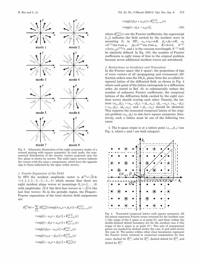
. Restrictions on Incidence and Truncationn the Fourier space (the k space), the projections of tipsf wave vectors of all (propagating and evanescent) dif-raction orders onto the Okxky plane form the so-called re-iprocal lattice of the diffracted field, as shown in Fig. 4here each point of the lattice corresponds to a diffractionrder. As stated in Ref. 10, to substantially reduce theumber of unknown Fourier coefficients, the reciprocal
attices of the diffraction fields excited by the eight inci-ent waves should overlap each other. Namely, the lat-ices ��m , n�, �−�m ,− n�, �− n ,�m�, � n ,−�m�, ��m ,− n�,−�m , n�, � n ,�m�, and �− n ,−�m� should be identical.his requires the truncated reciprocal lattice of the origi-al problem ��m , n� to also have square symmetry. Intu-
tively, such a lattice must be one of the following twoases:
1. The k-space origin is at a lattice point ��−s , −t� (seeig. 4, where s and t are both integers).
ig. 4. Truncated reciprocal lattice with square symmetry. Allhe points represent Fourier terms retained for the incident case(the origin of the k space is at point O), and those within the
ouble-dashed–dotted boundary are for the incident case 2 (therigin of the k space is at point O�). Two sets of symmetricaloints are marked by dashed circles [for case 1] and solid circlesfor case 2]. The points within other close boundaries representhe Fourier terms retained in numerical computation for fourases: dashed for Ex
�3�, solid for Ey�3�, dashed–dotted for Ex
�8�, andotted for E�8�.
y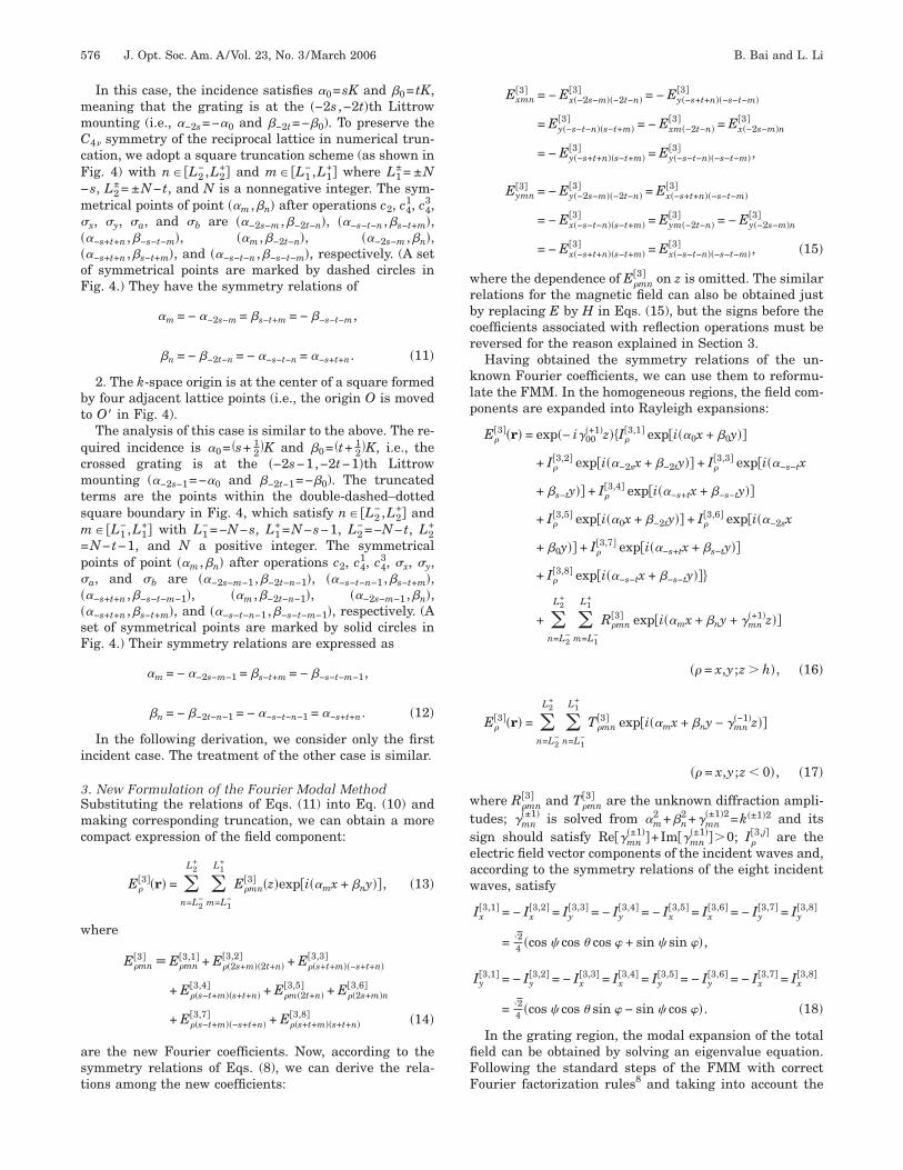
mmCcF−m���oF
bt
qcmtsm=p���sF
i
3Smc
w
ast
wrbcr
klp
wtseaw
fiFF
576 J. Opt. Soc. Am. A/Vol. 23, No. 3 /March 2006 B. Bai and L. Li
In this case, the incidence satisfies �0=sK and 0= tK,eaning that the grating is at the �−2s ,−2t�th Littrowounting (i.e., �−2s=−�0 and −2t=− 0). To preserve the4� symmetry of the reciprocal lattice in numerical trun-
ation, we adopt a square truncation scheme (as shown inig. 4) with n� �L2
−,L2+� and m� �L1
−,L1+� where L1
±= ±Ns, L2
±= ±N− t, and N is a nonnegative integer. The sym-etrical points of point ��m , n� after operations c2, c4
1, c43,
x, �y, �a, and �b are ��−2s−m , −2t−n�, ��−s−t−n , s−t+m�,�−s+t+n , −s−t−m�, ��m , −2t−n�, ��−2s−m , n�,�−s+t+n , s−t+m�, and ��−s−t−n , −s−t−m�, respectively. (A setf symmetrical points are marked by dashed circles inig. 4.) They have the symmetry relations of
�m = − �−2s−m = s−t+m = − −s−t−m,
n = − −2t−n = − �−s−t−n = �−s+t+n. �11�
2. The k-space origin is at the center of a square formedy four adjacent lattice points (i.e., the origin O is movedo O� in Fig. 4).
The analysis of this case is similar to the above. The re-uired incidence is �0= �s+ 1
2 �K and 0= �t+ 12 �K, i.e., the
rossed grating is at the �−2s−1,−2t−1�th Littrowounting (�−2s−1=−�0 and −2t−1=− 0). The truncated
erms are the points within the double-dashed–dottedquare boundary in Fig. 4, which satisfy n� �L2
−,L2+� and
� �L1−,L1
+� with L1−=−N−s, L1
+=N−s−1, L2−=−N− t, L2
+
N− t−1, and N a positive integer. The symmetricaloints of point ��m , n� after operations c2, c4
1, c43, �x, �y,
a, and �b are ��−2s−m−1, −2t−n−1�, ��−s−t−n−1, s−t+m�,�−s+t+n , −s−t−m−1�, ��m , −2t−n−1�, ��−2s−m−1, n�,�−s+t+n , s−t+m�, and ��−s−t−n−1, −s−t−m−1�, respectively. (Aet of symmetrical points are marked by solid circles inig. 4.) Their symmetry relations are expressed as
�m = − �−2s−m−1 = s−t+m = − −s−t−m−1,
n = − −2t−n−1 = − �−s−t−n−1 = �−s+t+n. �12�
In the following derivation, we consider only the firstncident case. The treatment of the other case is similar.
. New Formulation of the Fourier Modal Methodubstituting the relations of Eqs. (11) into Eq. (10) andaking corresponding truncation, we can obtain a more
ompact expression of the field component:
E��3��r� = �
n=L2−
L2+
�m=L1
−
L1+
E�mn�3� �z�exp�i��mx + ny��, �13�
here
E�mn�3� � E�mn
�3,1� + E��2s+m��2t+n��3,2� + E��s+t+m��−s+t+n�
�3,3�
+ E��s−t+m��s+t+n��3,4� + E�m�2t+n�
�3,5� + E��2s+m�n�3,6�
+ E��s−t+m��−s+t+n��3,7� + E��s+t+m��s+t+n�
�3,8� �14�
re the new Fourier coefficients. Now, according to theymmetry relations of Eqs. (8), we can derive the rela-ions among the new coefficients:
Exmn�3� = − Ex�−2s−m��−2t−n�
�3� = − Ey�−s+t+n��−s−t−m��3�
= Ey�−s−t−n��s−t+m��3� = − Exm�−2t−n�
�3� = Ex�−2s−m�n�3�
= − Ey�−s+t+n��s−t+m��3� = Ey�−s−t−n��−s−t−m�
�3� ,
Eymn�3� = − Ey�−2s−m��−2t−n�
�3� = Ex�−s+t+n��−s−t−m��3�
= − Ex�−s−t−n��s−t+m��3� = Eym�−2t−n�
�3� = − Ey�−2s−m�n�3�
= − Ex�−s+t+n��s−t+m��3� = Ex�−s−t−n��−s−t−m�
�3� , �15�
here the dependence of E�mn�3� on z is omitted. The similar
elations for the magnetic field can also be obtained justy replacing E by H in Eqs. (15), but the signs before theoefficients associated with reflection operations must beeversed for the reason explained in Section 3.
Having obtained the symmetry relations of the un-nown Fourier coefficients, we can use them to reformu-ate the FMM. In the homogeneous regions, the field com-onents are expanded into Rayleigh expansions:
E��3��r� = exp�− i�00
�+1�z��I��3,1� exp�i��0x + 0y��
+ I��3,2� exp�i��−2sx + −2ty�� + I�
�3,3� exp�i��−s−tx
+ s−ty�� + I��3,4� exp�i��−s+tx + −s−ty��
+ I��3,5� exp�i��0x + −2ty�� + I�
�3,6� exp�i��−2sx
+ 0y�� + I��3,7� exp�i��−s+tx + s−ty��
+ I��3,8� exp�i��−s−tx + −s−ty���
+ �n=L2
−
L2+
�m=L1
−
L1+
R�mn�3� exp�i��mx + ny + �mn
�+1�z��
�� = x,y;z � h�, �16�
E��3��r� = �
n=L2−
L2+
�n=L1
−
L1+
T�mn�3� exp�i��mx + ny − �mn
�−1�z��
�� = x,y;z � 0�, �17�
here R�mn�3� and T�mn
�3� are the unknown diffraction ampli-udes; �mn
�±1� is solved from �m2 + n
2 +�mn�±1�2=k�±1�2 and its
ign should satisfy Re��mn�±1��+Im��mn
�±1���0; I��3,j� are the
lectric field vector components of the incident waves and,ccording to the symmetry relations of the eight incidentaves, satisfy
Ix�3,1� = − Ix
�3,2� = Iy�3,3� = − Iy
�3,4� = − Ix�3,5� = Ix
�3,6� = − Iy�3,7� = Iy
�3,8�
=24 �cos � cos � cos � + sin � sin ��,
Iy�3,1� = − Iy
�3,2� = − Ix�3,3� = Ix
�3,4� = Iy�3,5� = − Iy
�3,6� = − Ix�3,7� = Ix
�3,8�
=24 �cos � cos � sin � − sin � cos ��. �18�
In the grating region, the modal expansion of the totaleld can be obtained by solving an eigenvalue equation.ollowing the standard steps of the FMM with correctourier factorization rules8 and taking into account the
sc
wimi1HE
st+mt4Ta�a
wmKa=rEAtN
irtaSaitdt
BAsca
−dqt
At
wmj
cgc
w
t�
hdtcE
B. Bai and L. Li Vol. 23, No. 3 /March 2006/J. Opt. Soc. Am. A 577
ymmetry relation of Fourier coefficients [Eqs. (15)], wean construct the reduced eigenvalue equation as
�FG − �k02�2��Exj
�3�
Eyj�3� = 0, �19�
here the column vector E��3�, constructed by concatenat-
ng the columns of the field amplitude matrix �E�mn�3� � [i.e.,
aking a mapping of �m ,n�→ j with m running throughts full range after each increment of n], takes only about/8 of the total Fourier coefficients as its components.owever, since Ex�−s��−t�
�3� �z�=Ey�−s��−t��3� �z�=Exm�−t�
�3� �z�=0 and
xm�s−t+m��3� �z�=−Eym�s−t+m�
�3� �z� from Eqs. (15), the dimen-
ions of Ex�3� and Ey
�3� are not the same. Ex�3� includes only
he terms with n� �−t+1,N− t−1� and m� �−s+ t+n1,N−s�; Ey
�3� contains the terms with n� �−t ,N− t� and� �−s+ t+n ,N−s� but excluding Ey�−s��−t�
�3� . Schematically,he points within the dashed and solid boundaries in Fig.
indicate the components of Ex�3� and Ey
�3�, respectively.hus, with symmetry considerations, the orders of Ex
�3�
nd Ey�3� are reduced from �2N+1�2 to �1/2�N�N−1� and
1/2�N�N+3�, respectively. Accordingly, the matrices Fnd G are
F =� U11�i,j� �k02�ij + U12�i,j�
− �k02�ij + U21�i,j� U22�i,j�
,
G =�− �i i�ij + V11�i,j� �i2�ij + V12�i,j�
− i2�ij + V21�i,j� �i i�ij + V22�i,j�
, �20�
here i and j are the row and column indices for each sub-atrix, and i has the same numbering rule as j; �ij is theronecker symbol; �i and i are the elements on the di-gonals of matrices ���ij= ���mn,pq=�m�mp�nq and � �ij� �mn,pq= n�mp�nq, respectively, where the mappingules of �m ,n�→ i and �p ,q�→ j are the same as that for˜
��3�; the submatrices Upq�i , j� and Vpq�i , j� are defined inppendix A. With symmetry simplification, the order of
he square eigenmatrix is reduced from 2�2N+1�2 to�N+1�.The remaining work is almost mechanical, i.e., obtain-
ng the modal expansions of the total fields in the gratingegion by solving Eq. (19), matching the boundary condi-ions at the interfaces between different spatial regions,nd finally solving the linear equation system with the-matrix algorithm14,15 to obtain the unknown Rayleighmplitudes in the homogeneous regions. It is worth not-ng that, when we exploit symmetry, the order of the ma-rices involved in the S-matrix implementation is also re-uced from 2�2N+1�2 to N�N+1�, which helps to speed uphe computation.
. Solutions of the Degenerate Symmetry Modesccording to Eq. (4), among the four doubly degenerateymmetry modes, only SP5 and SP8 need to be solved be-ause the other two modes are not excited. Taking SP8 asn example, we discuss its solution process.
The incident amplitude vector of SP8 is a�8�=1/2�1,1,0,0,1,−1,0,0�, meaning that there are only four inci-ent waves at mountings S1, S2, S5, and S6. Conse-uently, the Floquet–Fourier expansions of the total elec-ric field components are
E��8��r� = �
n=L2−
L2+
�m=L1
−
L1+
�E�mn�8,1��z� + E��2s+m��2t+n�
�8,2� �z� + E�m�2t+n��8,5� �z�
+ E��2s+m�n�8,6� �z��exp�i��mx + ny��
� �n=L2
−
L2+
�m=L1
−
L1+
E�mn�8� �z�exp�i��mx + ny��. �21�
ccording to Eqs. (9a), we can derive the symmetry rela-ions among the Fourier coefficients:
Exmn�8� = Ex�−2s−m��−2t−n�
�8� = Exm�−2t−n��8� = Ex�−2s−m�n
�8� ,
Eymn�8� = Ey�−2s−m��−2t−n�
�8� = − Eym�−2t−n��8� = − Ey�−2s−m�n
�8� ,
�22�
here the dependence of E�mn�8� on z is omitted. The sym-
etry relations for the magnetic field can also be obtainedust as was done in SP3.
Now we use the symmetry relations of Fourier coeffi-ients to reformulate the FMM. In the homogeneous re-ions, the Rayleigh expansions of the total electric fieldomponents are
E��8��r� = exp�− i�00
�+1�z��I��8,1� exp�i��0x + 0y��
+ I��8,1� exp�i��−2sx + −2ty�� ± I�
�8,1� exp�i��0x
+ −2ty�� ± I��8,1� exp�i��−2sx + 0y���
+ �m=L1
−
L1+
�n=L2
−
L2+
R�mn�8� exp�i��mx + ny + �mn
�+1�x3��
�� − x,y;z � h�, �23�
E��8��r� = �
n=L2−
L2+
�m=L1
−
L1+
T�mn�8� exp�i��mx + ny − �mn
�−1�z��
�� = x,y;z � 0�, �24�
here
Ix�8,1� = 1
2 �cos � cos � cos � + sin � sin ��,
Iy�8,1� = 1
2 �cos � cos � sin � − sin � cos ��; �25�
he upper and lower signs in Eq. (23) are used for �=x and=y, respectively.In the grating region, the reduced eigenvalue equation
as the similar form as Eq. (19) except for the followingifferences. The column vectors Ex
�8� and Ey�8�, which form
he eigenvector, take only about 1/4 of the total Fourieroefficients as their components. Ex
�8� contains the terms�8� with n� �−t ,N− t� and m� �−s ,N−s�, whereas E�8� is
xmn y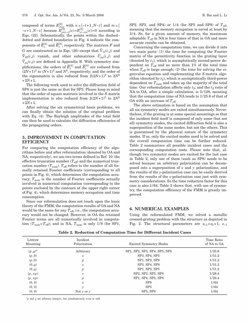
c−EdpGVVp�t+
Sti+
cwct
5EFrNecmpripoc
twrFt
Sm3aa
tm(pwgrdtNtO
attasimtTctisptfmctp
6UcF
578 J. Opt. Soc. Am. A/Vol. 23, No. 3 /March 2006 B. Bai and L. Li
omposed of terms Eynm�8� with n� �−t+1,N− t� and m� �
s+1,N−s� because Eym�−t��8� �z�=Ey�−s�n
�8� �z�=0 according toqs. (22). Schematically, the points within the dashed–otted and dotted boundaries in Fig. 4 indicate the com-onents of Ex
�8� and Ey�8�, respectively. The matrices F and
are constructed as in Eqs. (20) except that V11�i , j� and
22�i , j� vanish, and other submatrices Upq�i , j� and
pq�i , j� are defined in Appendix B. With symmetry sim-lifications, the orders of Ex
�8� and Ey�8� are reduced from
2N+1�2 to �N+1�2 and N2, respectively; and the order ofhe eigenmatrix is also reduced from 2�2N+1�2 to 2N2
2N+1.The following work used to solve the diffraction field of
P8 is just the same as that for SP3. Please keep in mindhat the order of square matrices involved in the S-matrixmplementation is also reduced from 2�2N+1�2 to 2N2
2N+1.After solving the six symmetrical basis problems, we
an finally obtain the solution of the original problemith Eq. (4). The Rayleigh amplitudes of the total field
an then be used to calculate the diffraction efficiencies ofhe propagating orders.
. IMPROVEMENT IN COMPUTATIONFFICIENCYor comparing the computation efficiency of the algo-ithms before and after reformulation (denoted by OA andA, respectively), we use two terms defined in Ref. 10: the
ffective truncation number �Teff� and the numerical trun-ation number �Tnum�. Teff refers to the number of all for-ally retained Fourier coefficients (corresponding to all
oints in Fig. 4), which determines the computation accu-acy; Tnum is the number of Fourier coefficients actuallynvolved in numerical computation (corresponding to theoints enclosed by the contours at the upper right cornerf Fig. 4), which determines memory occupation and timeonsumption.
Since our reformulation does not touch upon the basicheory of the FMM, the computation results of OA and NAould be the same for any Teff, i.e., the computation accu-
acy would not be changed. However, in OA the retainedourier terms are all numerically involved in computa-ion �Tnum=Teff�; and in NA, Tnum is only 1/8 (for SP1,
Table 2. Reduction of Computati
LittrowMounting
IncidentPolarization
�p ,q�a Arbitrary�p ,0� s�p ,0� p�0,q� s�0,q� p
�p , ±p� s�p , ±p� p(0, 0) x(0, 0) y(0, 0) Not x or y
ap and q are arbitrary integers, but simultaneously even or odd.
P2, SP3, and SP4) or 1/4 (for SP5 and SP8) of Teff,eaning that the memory occupation is saved at least by/4. So, for a given amount of memory, the maximumdoptable Teff in NA is four times of that in OA and moreccurate results can be obtained.Concerning the computation time, we can divide it into
wo main parts: (1) the time for computing the Fourieratrix of the permittivity function in the grating layer
denoted by t1), which is asymptotically second-power de-endent on Teff and no more than 1% of the total timehen Teff is large enough; (2) the time for solving the ei-envalue equation and implementing the S-matrix algo-ithm (denoted by t2), which is asymptotically third-powerependent on Tnum and takes up the majority of the totalime. Our reformulation affects only t2; and the t2 ratio ofA to OA, after a simple calculation, is 5/128, meaning
hat the computation time of NA tends to 1/25.6 of that ofA with an increase of Teff.The above estimation is based on the assumption that
ll six symmetry modes are exited simultaneously. Never-heless, if the grating is at some special mountings so thathe incident field itself is composed of only some (but notll) symmetry modes, the excited diffraction field is also auperposition of the same modes, but not the others. Thiss guaranteed by the physical nature of the symmetry
odes. If so, only the excited modes need to be solved andhe overall computation time can be further reduced.able 2 summarizes all possible incident cases and theorresponding computation costs. Please note that, al-hough two symmetry modes are excited for the last casen Table 2, only one of them (such as SP8) needs to beolved because an arbitrary polarization can be decom-osed into a superposition of x and y polarizations; andhe results of the y-polarization case can be easily derivedrom the results of the x-polarization case just with sym-etry considerations. So the time reduction factor for this
ase is also 1/64. Table 2 shows that, with use of symme-ry, the computation efficiency of the FMM is greatly im-roved.
. NUMERICAL EXAMPLESsing the reformulated FMM, we solved a metallic
rossed-grating problem with the structure as depicted inig. 2. The structural parameters are �+1=�b=1, �−1
me for Different Incident Cases
xcited Symmetry ModesTime Ratioof NA to OA
1, SP2, SP3, SP4, SP5, SP8 1/25.6SP3, SP4, SP5 1/51.2SP1, SP2, SP8 1/51.2SP3, SP4, SP8 1/51.2SP1, SP2, SP5 1/51.2
SP2, SP3, SP5, SP8 1/28.4SP1, SP4, SP5, SP8 1/28.4
SP8 1/64SP5 1/64
SP5, SP8 1/64
on Ti
E
SP
=s�tf1
chtecntwtt1
wsw
SOra2tw
7TbIdfidtmtmpn−tss1ctd
AIs
a
U
Frm
Fa
B. Bai and L. Li Vol. 23, No. 3 /March 2006/J. Opt. Soc. Am. A 579
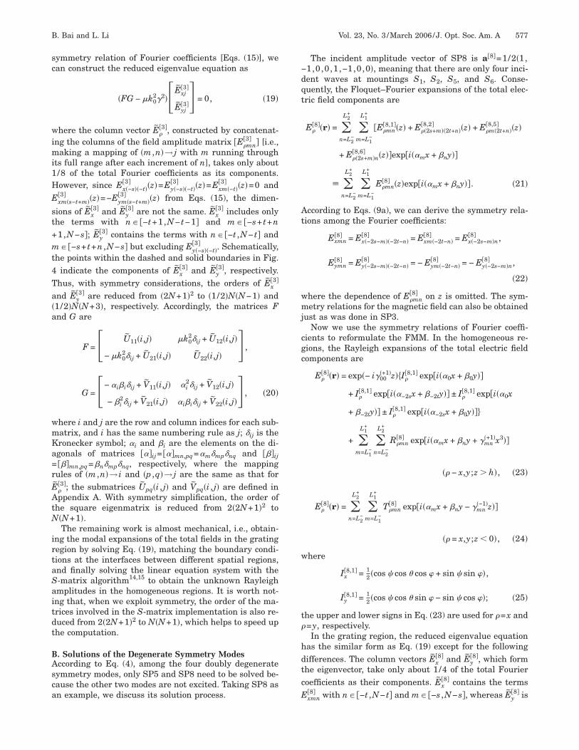
2.25, �a= �1.0+ i5.0�2, d=3�, and h=w=�. The grating isupposed to be at the �−4,−2�th Littrow mounting, i.e.,=48.190° and �=26.565°. The polarization angle is arbi-rarily selected as �=30°. All computations were per-ormed with MATLAB 6.1 on a desktop computer with a.5 GHz CPU and 256 Mbytes RAM.The diffraction efficiencies for three reflected orders
omputed by both NA and OA are shown in Fig. 5. As weave predicted, the results of two algorithms are alwayshe same at any Teff. However, the computer memory wasxhausted when Teff reached 625 �N=12� for OA, and theurves have not converged yet. For NA the memory wasot used up until Teff=2401 �N=24�, which is almost fourimes of that in OA, and the curves have converged fairlyell. Figure 6 shows the total computation time costs of
he two algorithms. Obviously, NA is much more efficienthan OA and their time ratio asymptotically tends to/25.6 with an increase of Teff.Finally we consider a special case of normal incidence
ith x polarization. The grating parameters remain theame as above except for d=2.5�, and the computationas performed with T =625. According to Table 2, only
ig. 5. Convergence of the �−1,−3�th, �−1,0�th, and �−4, +1�theflected orders of the metallic crossed grating with square sym-etry, which were computed by both NA and OA.
ig. 6. Comparison of the total computation time costs of NAnd OA.
eff
P8 needs to be solved in NA. We still used both NA andA to solve this problem. Once again, they gave the same
esults, and the total computation times consumed by NAnd OA were 51 and 1910 s, respectively, both including2 s of the time t1. If we exclude this part of time, thenhe time t2 ratio of NA to OA is 1/65.1, which agrees wellith the theoretical prediction.
. SUMMARYhe FMM for crossed gratings with square symmetry haseen reformulated by use of the group-theoretic approach.n the new formulation, a crossed-grating problem is firstecomposed into six symmetrical basis problems whoseeld distributions are the symmetry modes (four are non-egenerate and the other two are doubly degenerate) ofhe grating. Then the symmetry relations of the electro-agnetic fields in the symmetry modes are used to reduce
he number of unknowns in computation. After the sym-etrical basis problems are solved, their solutions are su-
erposed to get the solution of the original problem. In theew FMM, the grating is required to be at the �−2s ,2t�th or �−2s − 1,−2t − 1�th Littrow mounting, and theruncated reciprocal lattice should also have the squareymmetry. After reformulation, the memory occupation isaved by 3/4 and the time consumption is reduced to/25.6 to 1/64 of the original one for different incidentases. Numerical examples are given to show the effec-iveness of the new FMM and verify the theoretically pre-icted, highly improved computation efficiency.
PPENDIX An Eqs. (20), the submatrices Upq�i , j� and Vpq�i , j� are con-tructed as
1. when j corresponds to �m ,−t� (occurring only in Up1
nd Vp2),
Up1�i,j� = Up1�i,j� − Up1�i,j1� − Up2�i,j2� + Up2�i,j3�,
V12�i,j� = V12�i,j� − V12�i,j1�,
V22�i,j� = V21�i,j2� − V21�i,j3�; �A1�
2. when j corresponds to �m ,s− t+m� (occurring only in˜
p1 and Vp2),
Up1�i,j� = Up1�i,j� − Up1�i,j1� + Up1�i,j2� − Up1�i,j3�
+ Up2�i,j� − Up2�i,j1� − Up2�i,j2� + Up2�i,j3�,
V12�i,j� = �i i�ij + V12�i,j� − V12�i,j1� + V12�i,j2� − V12�i,j3�,
V22�i,j� = − V21�i,j� + V21�i,j1� + V21�i,j2� − V21�i,j3�; �A2�
3. otherwise,
I
j��r��
ATs
a
�
Id
ATDN6tt
R
1
1
1
1
1
1
580 J. Opt. Soc. Am. A/Vol. 23, No. 3 /March 2006 B. Bai and L. Li
Up1�i,j� = Up1�i,j� − Up1�i,j1� + Up1�i,j4� − Up1�i,j5�
− Up2�i,j2� + Up2�i,j3� + Up2�i,j6� − Up2�i,j7�,
Up2�i,j� = Up2�i,j� + Up1�i,j2� − Up1�i,j3� + Up1�i,j6�
− Up1�i,j7� − Up2�i,j1� − Up2�i,j4� + Up2�i,j5�,
V11�i,j� = − V12�i,j2� + V12�i,j3� − V12�i,j6� + V12�i,j7�,
V12�i,j� = V12�i,j� − V12�i,j1� + V12�i,j4� − V12�i,j5�,
V21�i,j� = V21�i,j� − V21�i,j1� − V21�i,j4� + V21�i,j5�,
V22�i,j� = V21�i,j2� − V21�i,j3� − V21�i,j6� + V21�i,j7�. �A3�
n Eqs. (A1)–(A3),
U11�i,j� = �i ��i,j−1 j,
U12�i,j� = − �i ��i,j−1�j,
U21�i,j� = i ��i,j−1 j,
U22�i,j� = − i ��i,j−1�j,
V12�i,j� = − �k02�����i,j,
V21�i,j� = �k02�����i,j; �A4�
n �n=1, . . . , 7� correspond to �−2s−m ,−2t−n�,−s+ t+n ,−s− t−m�, �−s− t−n ,s− t+m�, �m ,−2t−n�,−2s−m ,n�, �−s+ t+n ,s− t+m�, and �−s− t−n ,−s− t−m�,espectively, when j corresponds to �m ,n�; ��, �����, and���� are Toeplitz matrices of the Fourier coefficients of�x ,y�, whose definitions are given in Ref. 8.
PPENDIX Bhe submatrices Wpq�i , j��W=U ,V ;p ,q=1,2� are con-tructed as
1. when j corresponds to �−s ,−t� (occurring only in Up2
nd V21),
Wpq�i,j� = Wpq�i,j�; �B1�
2. when j corresponds to �m ,−t� or �−s ,n�, but not−s ,−t� (occurring only in Up2 and V21),
Wpq�i,j� = Wpq�i,j� + Wpq�i,j1�; �B2�
3. otherwise,
Up1�i,j� = Up1�i,j� + Up1�i,j1� − Up1�i,j4� − Up1�i,j5�,
˜
Up2�i,j� = Up2�i,j� + Up2�i,j1� + Up2�i,j4� + Up2�i,j5�,V12�i,j� = V12�i,j� + V12�i,j1� − V12�i,j4� − V12�i,j5�,
V21�i,j� = V21�i,j� + V21�i,j1� + V21�i,j4� + V21�i,j5�. �B3�
n Eqs. (B1)–(B3), jn, Upq�i , j�, and Vpq�i , j� have the sameefinitions as those in Appendix A.
CKNOWLEDGMENThis work is supported by the National Science Fund foristinguished Young Scholars established by the Nationalatural Science Foundation of China under project0125514. The authors can be reached at the address onhe title page or by e-mail at [email protected] and [email protected].
EFERENCES1. B. Bai and L. Li, “Reduction of computation time for
crossed-grating problems: a group-theoretic approach,” J.Opt. Soc. Am. A 21, 1886–1894 (2004).
2. Ph. Lalanne and D. Lemercier-Lalanne, “On the effectivemedium theory of subwavelength periodic structures,” J.Mod. Opt. 43, 2063–2085 (1996).
3. Ph. Lalanne, “Improved formulation of the coupled-wavemethod for two-dimensional gratings,” J. Opt. Soc. Am. A14, 1592–1598 (1997).
4. C. Zhou and L. Li, “Formulation of Fourier modal methodof symmetric crossed gratings in symmetric mountings,” J.Opt. A, Pure Appl. Opt.6, 43–50 (2004).
5. Z. Y. Li and K. M. Ho, “Application of structuralsymmetries in the plane-wave-based transfer-matrixmethod for three-dimensional photonic crystalwaveguides,” Phys. Rev. B 68, 245117 (2003).
6. R. Bräuer and O. Bryngdahl, “Electromagnetic diffractionanalysis of two-dimensional gratings,” Opt. Commun. 100,1–5 (1993).
7. E. Noponen and J. Turunen, “Eigenmode method forelectromagnetic synthesis of diffractive elements withthree-dimensional profiles,” J. Opt. Soc. Am. A 11,2494–2502 (1994).
8. L. Li, “New formulation of the Fourier modal method forcrossed surface-relief gratings,” J. Opt. Soc. Am. A 14,2758–2767 (1997).
9. C. Hammond, The Basics of Crystallography andDiffraction (Oxford U. Press, 2001).
0. B. Bai and L. Li, “Group-theoretic approach to theenhancement of the Fourier modal method for crossedgratings: C2 symmetry case,” J. Opt. Soc. Am. A 22,654–661 (2005).
1. B. Bai and L. Li, “Group-theoretic approach to enhancingthe Fourier modal method for crossed gratings with one ortwo reflection symmetries,” J. Opt. A, Pure Appl. Opt. 7,271–278 (2005).
2. B. Bai and L. Li, “Group-theoretic approach to enhancingthe Fourier modal method for crossed gratings of planegroup p3,” J. Mod. Opt. 52, 1619–1634 (2005).
3. J. F. Cornwell, ed., Group Theory in Physics: AnIntroduction (Academic, 1997), App. C, pp. 299–318.
4. L. Li, “Formulation and comparison of two recursive matrixalgorithms for modeling layered diffraction gratings,” J.Opt. Soc. Am. A 13, 1024–1035 (1996).
5. L. Li, “Note on the S-matrix propagation algorithm,” J.
Opt. Soc. Am. A 20, 655–660 (2003).