Embed Size (px)
Citation preview

HAMBAKER GROUP
Process Equipment
www.hambakergroup.com

02
HAMBAKER GROUP
Established in the 19th Century, The Ham Baker Group is a market leading, global organisation dedicated to the design and manufacture of innovative products, for the water, waste water and process sectors.
Ham Baker’s name is synonymous with precision-engineered products and adding value to customer’s individual requirements. The group designs complete engineered solutions, with experts on hand across all sectors to cover customers individual process and flow needs.
The Ham Baker Group is unique amongst modern day suppliers in being able to offer product to all areas of water, waste water and process applications. The understanding of individual applications informs the design of complementary products and services resulting in the ability to be able to offer complete engineered solutions which deliver optimum performance.
A fully equipped, UK, in-house manufacturing facility complemented by state-of-the-art design facilities provides customers with bespoke engineered solutions, capable of operating to industry leading standards.
A dedicated research and development team, working in conjunction with world renowned universities delivers innovative solutions to process applications, providing significant infrastructure benefits to customers.
Significant investment in new processes, design facilities and CNC machinery complements the apprentice-trained workforce with skills in manufacture, procurement, project management, design and development and logistics to satisfy the most demanding customer requirements.
With manufacturing bases in the UK, China, Hong Kong, UAE and Australia we are able to offer engineered solutions worldwide.

03

04

Power Engaged Screen 06
Continuous Chain Raked Screen 08
Travelling Fine Screen 10
Double Flow Bandscreen 12
Eel Friendly Bandscreen 14
Drum & Cup Screen 16
SiderPol Screen-Compactor 18
Integrated Compact Sewage Pre-Treatment Systems 24
Self-contained Inlet Plant 28
Grit Star 30
Cross-flow Detritors 32
Settlement Tank Scrapers 34
Suction Lift Scrapers 38
Dipping Scumboxes and ScumAway 39
Sludge Thickeners 41
Scraper loading data acquisition 42
Flow Control Baffles and other Tank Accessories 43
Scraper upgrades, retrofits and refurbishments 45
Self-seal Distributor 46
Cresset Distributor 47
Paddlewheel Distributor 49
Travelling Distributor 50
Distributor Siphons 52
Services 54
05
Process Equipment

Power Engaged Screen
06
DescriptionRobust front raked coarse screen suitable for raw sewage applications. It has a proven design with track record stretching back to 1997 and has been installed at over 30 sites in the UK.Debris is cleared from the screen grid by a chain operated rake travelling up the intake face of the grid. The front edge of the skip is fitted with replaceable tine plates which project into the grid. The rake is raised and lowered by two conveyor chains within the skip. A current sensing overload protection device within the control panel can be used to protect the mechanism during both the ‘up’ and ‘down’ movements of the skip.Guides for the rake are attached to the supporting structure; their position relative to the screen grid is controlled by an actuator attached to a structure spanning the chamber upstream of the screen. For installation in deep chambers the guides can be pivoted at a suitable position below floor level but above top water level reducing the loading on the guide control mechanism. On the downward travel of the rake, the control mechanism is operated and the guides are swung clear of any debris on the face of the grid. At the bottom of the rake travel (underwater) the mechanism is operated, swinging the guides back towards the screen grid, forcing the tines of the rake into the spaces between the grid bars. This ensures positive engagement of the tines with the grid without relying on the weight of the skip.
If the rake contacts a rigid obstruction during its upward travel, the power demand of the drive motor will rise and the surge will be sensed to signal the actuator to withdraw the tines from the grid. When the resistance to movement of the rake is lower than the power available from the motor, the movement of the rake will continue, if this occurs before the tines have cleared the obstruction, part of the debris will be cut away by the ends of the tines. Any unusual obstruction as the tines are pushed into the grid will signal the screen motor to start and hoist the rake clear of the obstruction. The sensing devices are provided with adjustable time delays before cutting out on overload. If this method of protection does not clear the obstruction within the pre-set delay the screen should cut out and the appropriate overload lamp on the panel illuminates.

Key Features ■ Suitable for channel widths from 1m up to 3.0m,
and depths up to 5.0m ■ Bar gaps down to 10mm ■ Standard screen angle 75° to horizontal ■ Suitable for flows up to about 2500l/s given
appropriate water levels ■ Tapered bar to minimise blockages ■ All moving parts fully guarded ■ Profiling function to work around large obstacles
keeps screen operational where other screens would stop
■ Screen can discharge into a launder trough, screw conveyor or belt conveyor
■ No wash water requirement ■ Screen mechanism parked out of the flow when
not operational ■ Quiet operation of screen, as the skip is engaged
with the screen bars under control and not allowed to drop into mesh with grid bars, as is the case with gravity type bar screens
■ All screens are bespoke designed for the particular application, and are suitable for installing in new channels or retrofitting in existing channels
■ Standard material of construction is painted MS with mild steel chains.
Options ■ Single, dual or variable speed drive ■ 304 or 316 stainless steel main structure, grid
bars or chains ■ ATEX certified screens for use in hazardous areas ■ Various bar gaps and bar sizes to suit
customer requirements ■ Control panel and field cabling.
07
Continuous Chain Raked Screen
08
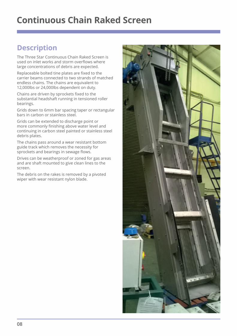
DescriptionThe Three Star Continuous Chain Raked Screen is used on inlet works and storm overflows where large concentrations of debris are expected. Replaceable bolted tine plates are fixed to the carrier beams connected to two strands of matched endless chains. The chains are equivalent to 12,000lbs or 24,000lbs dependent on duty.Chains are driven by sprockets fixed to the substantial headshaft running in tensioned roller bearings.Grids down to 6mm bar spacing taper or rectangular bars in carbon or stainless steel.Grids can be extended to discharge point or more commonly finishing above water level and continuing in carbon steel painted or stainless steel debris plates.The chains pass around a wear resistant bottom guide track which removes the necessity for sprockets and bearings in sewage flows.Drives can be weatherproof or zoned for gas areas and are shaft mounted to give clean lines to the screen.The debris on the rakes is removed by a pivoted wiper with wear resistant nylon blade.

The Three Star Continuous Chain Raked Screen is front raked bar screen which is best suited to pumped flow systems.Grid depths are selected to suit the water levels that the screen will see in operation. The gap between the top of the grid and discharge point is bridged by a continuous series of solid debris plates. The rakes pull trapped screenings up the bars and debris plates, to the discharge point.
Key Features ■ Maximum channel width 4.0m. ■ Maximum channel depth 12.0m. ■ Front raked. ■ Single full width rake head. ■ Dependent on channel width and depth bar
spaces down to 6mm are available. ■ No washwater required. ■ Multiple carrier beams give a frequent raking
action which ensures high concentrations of debris are effectively removed.
■ Replaceable rake heads. ■ Standard screen angle 75° to horizontal. ■ Debris is removed from the rakes by a pivoted
wiper with replaceable UHMW PE blade, at the top of the screen.
■ Standard material of construction is painted MS structure, grid and rakes, with mild steel zinc plated chains.
■ Multiple rakes are fastened to two endless chains which are driven by sprockets powered by a shaft mounted gearmotor at the top of the screen.
■ Chains pass round a wear resistant guide track at the bottom of the screen which removes the need for sprockets and bearing in the flow.
■ Rectangular or taper section bars. ■ All screens are bespoke designed for the
particular application, and are suitable for installing in new channels or retrofitting in existing channels.
Options ■ Control panel and field cabling.
■ ATEX certified screens for use in hazardous areas.
■ Single, dual or variable speed drive.
■ Stainless steel 304 or 316 structure, grid, rakes and chains
09

Travelling Fine Screen
DescriptionOur Travelling Fine Screen incorporates fabricated panels manufactured from pre-formed stainless steel perforated plate with apertures sized to suit specific applications. Panel design allows easy replacement in case of accidental damage whilst being securely fastened to the special strength 8” (203mm) pitch roller link chain.Panel cleaning is via a 2-stage cleaning process. First, a solid filled modular rotary brushing system with optimised position and bristle configuration removes the majority of screenings. The brushing system allows speedy replacement and adjustment. Second, wash water jets provide the final polish and ensure the rear cavity of the equipment remains free from blockage.Each panel has a replaceable side seal manufactured from bearing grade ultra-high molecular weight polyethylene fitted between the chain and panel to effect a close tolerance seal, with the seal fitted to the screen structure.
The main structural side plates are manufactured for strength and rigidity. These plates incorporate side outlet passages at flow level to allow passage of screened flow minimising headloss.The high strength chains run in ultra high molecular weight polyethylene guides and are driven by sprockets attached to the head shaft running in ball bearing plummer blocks. The drive is from a shaft mounted gearbox with a choice of motor types to suit specific applications.The drive continually moves panels from the screening zone, in the channel in front of the equipment, to the cleaning mechanism where the debris is removed from the perforated panels.The fine screen is fully guarded by stainless steel covers fastened to the main side structure.The fine screen can be inched forward, in case of mechanical stoppage and hinged to pivot out of flow for maintenance purposes. Dual speed units can be supplied.Screenings capture ratio of 79% as assessed at the national Screen Evaluation facility, Chester le street.
10

Key Features ■ Unique cutaway side plate design helps
reduce headloss. ■ Screenings Capture Ratio 79% ■ Incorporates high open area screening media to
improve hydraulic and capture performance. ■ Rotary brush cleaning mechanism combats
hairpinning, even when used with minimal wash water.
■ Fully retractable spray bar allows speedy nozzle unclogging.
■ Engineering bearing grade plastic side sealing system, helps prevent solids bypass and offers exceptional abrasion resistance.
■ Bespoke design for retrofitting or new chamber installations up to 3m wide.
Proven hydraulic and capture performance established during
independent trials at the National Screen Evaluation Facility Chester
le Street conducted by UKWIR
11

Double Flow Bandscreen
DescriptionScreening panels are carried on a vertical travelling path, between chains suspended from substantial sprockets on a head shaft. The chains/screen panels and guides are contained in a carbon steel or stainless steel screen support structure. A feature of this type of screen is its high capacity per width ratio and ability to deal with large variations in water levels and depths.Dependant upon the size of screen, the frame will be fabricated from rolled steel sections suitably braced to withstand loads or from pressed and fabricated plate in stainless steel or carbon steel. The head section is fabricated to hold the head shaft in guides and incorporates spray pipes and discharge trough. Covers are manufactured in stainless steel and have inspection windows fitted as standard.The chains are at pitches of 200, 300 or 450mm depending on the size of the screen. Links are carbon steel plated or stainless steel and are fitted with moulded nylon rollers sized to suit the screen.
Drive to the head shaft, which is supported in heavy duty roller bearings, is normally by a shaft mounted gear reducer often with two speed motor. Motors can be fitted with torque limiting coupling or preferably current sensing overload in control, to prevent damage due to obstruction or overload.The panel frames are of mild steel or stainless steel construction secured to the chain by stainless steel bolts. The frame carries plastic perforated panels or stainless steel meshes depending upon application and can be removed from outside the screen. The trailing edge of the panel is extended forward to form platforms for lifting larger debris.Each each panel is fitted with shaped seal plates. This corresponds with fixed side seals to give minimum clearance at sealing between clean and unscreened water.The screens are fitted with spray header pipe(s) each with a row of jets to wash debris from the panels into the debris trough incorporated into the head covers. Debris troughs can be fitted with extra sparge water supply, dependant upon debris loading.
12

Key Features ■ High capacity per width ratio. ■ Carry over prevented. ■ Thick plate perforated plastic or stainless steel
mesh panels. ■ Screen widths of up to 4.0m and depths of 20m
can be provided. ■ Screening down to 3mm where required. ■ Heavy duty chains of proven design for low
maintenance. ■ Highly efficient side sealing system prevents
screenings transfer downstream. ■ Easy removable panels for ease of maintenance.
Proven hydraulic and capture performance established during
independent trials at the National Screen Evaluation Facility Chester
le Street conducted by UKWIR
13

Eel Friendly Double Flow ‘Out to In’ Bandscreen
14
Description ■ Robust screen suitable for river intake
applications ■ High flow capacity per channel width ratio ■ ‘Out to In’ flow path configuration ■ Carry over prevented ■ Woven wire mesh panels - nominally 6mm
perforations ■ All moving parts fully guarded ■ Also available in an ‘In to Out’ configuration for
raw sewage applications
Key Features ■ Two stage panel cleaning. The first stage is for
the eels using a low pressure spray bar and the second is for general debris, using a high pressure spray bar, with a dedicated outlet for each
■ Removed eels are gently deposited into a trough which can be configured to discharge up or downstream of the screen
■ Fully retractable spray bar allows speedy nozzle unclogging
■ Minimum channel width 1.1m ■ Maximum channel depth 12.0m ■ Suitable for flows up to about 7000l/s given
appropriate water levels

15
Options ■ Single, dual or variable speed drive ■ Covers from stainless steel or plastic ■ 304 or 316 Stainless steel main structure, panels
and chains ■ Supply to site in sections for assembly in situ,
where access is restricted or crane capacity limited
■ Panel perforations down to 3mm ■ Control panel and fi eld cabling ■ DWI/WRAS compliant materials

Drum & Cup Screens
DescriptionDrum and Cup screens offer a simple and robust solution to applications where there is a requirement to screen large volumes of water. Typical applications include power generation intakes and desalination plants. Over many years the cup screen, in particular, has been used on sewage works for fine inlet screening and sea outfall use.Both drum and cup screens are supplied with perforated stainless or plastic panels for sewage applications, and woven wire mesh for water intakes. The standard aperture size is 6mm, for both sewage and water applications, with the option to go down to 3mm for water intakes. As the flow passes through the screen, debris adheres to the panels and is washed of, by an externally mounted, high pressure spray, into debris hoppers mounted at operating floor level. Larger debris is lifted up by elevating trays. The debris hoppers are covered by a spraybox to eliminate unwanted spray. Depending on the application the removed debris is either washed and compacted, before being discharged into a skip, or re dewatered in a mesh basket.
Key Features ■ Simple and robust design to screen large volumes
of water ■ Perforated panels in steel or thick plastic
depending on application ■ Cup Screens from 1 metre diameter ■ Drum Screens up to 18 metre diameter ■ Screening down to 2mm where required ■ Widths up to 4 metre ■ Efficient sealing system – no carry over ■ Standard material of construction is painted MS.
Options ■ Single, dual or variable speed drive ■ 304 or 316 Stainless steel main structure ■ ATEX certified screens for use in hazardous areas ■ Control panel and field cabling ■ Rotating brush for enhanced panel cleaning on
sewage applications.
16

Drum screens are designed to give the maximum hydraulic loading and run on substantial shafts, mounted in heavy duty roller bearings with sealing surfaces metal sprayed and ground to give long seal life. Cast iron racks mounted on the screen periphery engage with a high density nylon pinion giving long, trouble free life.
On all screens the influent is sealed from the effluent by efficient flexible neoprene rubber seals suitably shielded against mechanical damage and running on high density plastic seal flats.
17
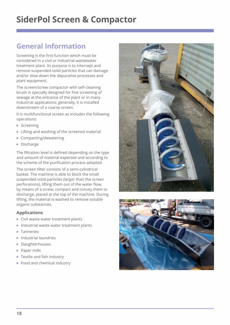
General InformationScreening is the first function which must be considered in a civil or industrial wastewater treatment plant. Its purpose is to intercept and remove suspended solid particles that can damage and/or slow down the depurative processes and plant equipment.
The screen/screw compactor with self-cleaning brush is specially designed for fine screening of sewage at the entrance of the plant or in many industrial applications; generally, it is installed downstream of a coarse screen.
It is multifunctional screen as includes the following operations:
■ Screening ■ Lifting and washing of the screened material ■ Compacting/dewatering ■ Discharge
The filtration level is defined depending on the type and amount of material expected and according to the scheme of the purification process adopted.
The screen filter consists of a semi-cylindrical basket. The machine is able to block the small suspended solid particles (larger than the screen perforations), lifting them out of the water flow, by means of a screw, compact and convey them to discharge, placed at the top of the machine. During lifting, the material is washed to remove soluble organic substances.
Applications ■ Civil waste water treatment plants ■ Industrial waste water treatment plants ■ Tanneries ■ Industrial laundries ■ Slaughterhouses ■ Paper mills ■ Textile and fish industry ■ Food and chemical industry
SiderPol Screen & Compactor
18

05-0362 Spiral with brushes
05-0362 Compaction area
05-0362 Basket with conical zone
19

Construction features (see layout) Screen screw compactor model 05-0362, built using the shaftless screw (anti-clogging spiral) technology, to be installed in the channel or in a steel container.
Screening area consists of a semi-cylindrical filter basket, with holes of variable diameter according to the flow to be treated. For special applications, we offer customized filter baskets.
Screw conveyor with special modular brushes bolted along an helical edge to provide cleaning of the semi-cylindrical screen during the rotation of the spiral.
Lateral plastic strips, reinforced with metal mesh, to allow the seal of the filter screen to the side walls of the channel.
Wear resistant plates bolted inside the housing of the spiral.
Cylindrical compaction zone for pressing the screened material, complete with flexible pipe to drain the liquid and top cover for inspection.
Conical discharge outlet complete with full opening to prevent possible clogging of the compacted screened material during unloading.
Adjustable foot support to allow the lifting of the tilting screen screw.
Installation in channel or in steel container.
Dimensions and level of filtration are determined according to the characteristics of the channel in which the screen screw compactor is installed, the desired discharge height and the flow to be treated
20

Brushes bolted and circular holes basket
21

Strengths ■ Multifunctional: screening, lifting and cleaning of
the screened material, compaction/dewatering, discharge
■ Easy and quick to install ■ Closed structure to avoid bad smells ■ Reduced maintenance ■ Tested at the National Screen Evaluation Facility
at Chester-le-Street STW – Average Screenings Capture Ratio = 51%
Accessories ■ Basket with a trapezoidal bars ■ Screen washing device ■ Transport area washing device ■ Compaction zone washing device ■ Control cabinet ■ Bagging system for screened material ■ Transport area insulation for compaction at
low temperatures ■ Without compaction zone ■ Installation in a steel container tank ■ Vertical Installation for flanged connection
to pipeline
Machine code 05-0362
Screen screw type Without central shaft
Diameter 200mm 300mm 400mm 500mm 600mm 700 mm
Spiral type Reinforced Conical
Inclination 35° to 45°
Length up to 12m
Basket cleaning With brushes bolted
Screen perforation 2mm 3mm 5mm 7mm
Basket type Circular holes
Rated power 0,55kW to 1,1 kW
Rotation speed 10 rpm
Compaction degree 40% to 60 %
Structural work materials AISI304L AISI316L
Spiral material Special steel AISI304L AISI316L
Wear-resistant coating Stainless steel plates
22

Machine in operation
Machine in operation
Shipping phase
23

General informationThe pre-treatment provides screening, sand removal and eventually oil and grease removal from sewage. The pre-treatment is as a result of the need to protect the civil or industrial wastewater treatment plants. Its purpose is to intercept and remove coarse solids, sands and oils that can damage and/or slow down the subsequent depurative processes and plant equipment, or obstruct the pipelines.
These compact systems consist of steel pre-treatment facilities, which do not require civil works for installation.
ApplicationsCivil waste water treatment plants
Industrial waste water treatment plants: tanneries, industrial laundries, slaughterhouses, paper mill, textile and fish industry, food and chemical industry.
05-0364Compact system for sewage tanker acceptance with screening and compaction
The sewage pre-treatment station model 05-0364 is equipped with a screen screw seated in a steel tank, to filter waste water and remove the coarse materials. To do this the screen screw is equipped with a perforated metal sheet semi-cylindrical screen (basket) and a screw conveyor.
The screen screw without central shaft (model 05-0362) minimizes the risks associated with possible clogging caused by rags, plastic etc.
The screen works with “clogging” logic. It starts only when the level sensor, placed inside the acceptance plant, is enabled. This logic guarantees a pre-filtration caused by the sewage solids which settle on the basket, blocking the holes.
This compact system includes a male ball joint for direct connection to a sewage tanker, with an automatic flow control valve operated by the level sensor placed inside the machine.
The system, contained in a suitable tank, is hermetically sealed and can be installed even in limited spaces.
Integrated Compact Sewage Pre-Treatment Systems
In the filtration area, the system is equipped with washing bar complete with solenoid control and nozzles, with two purposes: cleaning the filtration area and partial washing of the screenings with a consequent reduction of organic matter (odour reduction in the subsequent screenings storage zone).
Strengths ■ Multifunctional: screening, lifting and cleaning of
the screened material, compaction/dewatering, discharge
■ Easy and quick to install ■ Closed structure to avoid bad smells ■ Reduced maintenance ■ Sewage tanker quick discharge
Accessories ■ Screening bagging system ■ Control cabinet ■ Version with belt screen model 05-0350
Control cabinet
24
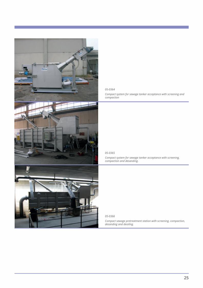
05-0364
Compact system for sewage tanker acceptance with screening and compaction
05-0365
Compact system for sewage tanker acceptance with screening, compaction and desanding.
05-0366
Compact sewage pretreatment station with screening, compaction,desanding and deoiling.
25

Compact system for sewage trucks acceptance model 05-0364
Maximum flow for water with 200 ppm SS
Ltot Linf Hdis Htot Hinl Flow Valve R.P.
Screen R.P.
Inlet – Male
Spherical Outlet
Model [mm] [mm] [mm] [mm] [mm] [m3/h] [kW] [kW] [DN] [DNPN10]
05-0364-50 4000 2110 1500 2200 800 50 0,18 0,55 100 200
05-0364-100 5100 3710 1990 2900 1100 100 0,18 1,1 100 200
Machine code 05-0364
Screw conveyor type Without central shaft
Models 50-100
Basket clearing With bolted brushes
Basket spacing (drilling) 5-7 mm
Basket type With round holes -
Rated power 0.55kW-1.1kW
Rotation speed 10 rpm
Compaction degree 40-60%
Chassis materials AISI304L AISI316L
Spiral material
High strength carbon steel AISI304L AISI316L
Wear-resistant coating Stainless steel plates
26

05-0365Compact system for sewage tankers acceptance with screening, compaction and desanding
The sewage pre-treatment station model 05-0365, combines the functionality of the 05-0364 model with the additional desanding treatment.
05-0366Compact sewage pre-treatment station with screening, compaction, desanding and deoiling.
The compact stations model 05-0366 designed to solve the problem of sewage pre-treatment at the entrance of small plants. They allow, avoiding the construction of suitable reinforced concrete tanks,
to perform the following steps: screening and compaction, desanding. In addition it is available the 05-0366 GG model which also makes the deoiling treatment.
Available materials and their combinations, performance, are the same as for the 05-0364 model.
27

Self-contained Inlet Plant
DescriptionA combined package of screening and grit removal is a pre-requisite of wastewater treatment to make the ongoing effluent a manageable and consistent medium entering the next phase of treatment.The system includes fabricated tanks which are modular or site specific to suit the flows and location. Depending on the flow and operating regime we can offer Travelling Fine or Band Screens.
Travelling Fine Screens: ■ Unique cutaway side plate design helps reduce
head loss ■ Screenings Capture Ratio 79% ■ Incorporates high open area screening media to
improve hydraulic and capture performance ■ Auto adjusting rotary brush cleaning mechanism
combats hair-pinning, even when used with minimal wash water (FE)
■ Washing debris plate ■ Fully retractable spray bar allows speedy nozzle
unclogging
Band Screens: ■ High capacity per width ratio ■ Carry over prevented ■ Thick plate perforated plastic or stainless steel
mesh panels ■ Screening down to 3mm where required ■ Heavy duty chains of proven design for low
maintenance ■ Highly efficient side sealing system prevents
screenings transfer downstream
■ Easy removable panels for ease of maintenance
28

Screenings Handling (Starwash): ■ Impressive volume reduction and dryness fraction ■ Pioneering cleaning techniques ■ Available in various body diameters to
accommodate varying throughput requirements: 150mm, 200mm and 300mm
■ Stand alone, under screen or integral screen mounted
■ Enhanced reliability – does not use cutter blades or macerators
■ Not subject to excessive wear in gritty conditions
Grit Removal (Gritstar): ■ Efficient removal of both faecal and vegetable
matter resulting in a cleaner grit with considerably lower organic content
■ Low cost and low energy use ■ Compact design ■ High efficiency - takes full advantage of
gravitational settlement ■ Simple, low rotating paddle mechanism, easy to
maintain ■ 95% removal of grit greater than 315 microns in
size with a S.G.>2.65
Benefits ■ ‘One Stop Shop’ ready to go Inlet Works ■ Manufactured in our works in a controlled factory
environment ■ Pre-wired and pre-commissioned in our works ■ Designed to provide easy maintenance and access
once installed ■ Single delivery and set into position ■ Minimal civil works required on site ■ Time on site greatly reduced ■ Health & Safety risks on site are minimised ■ Capacity – to suit client flow rate requirements ■ Typically 50 to 700l/s
29

Grit Star
DescriptionA combined package of screening and grit removal is a pre-requisite of wastewater treatment to make the ongoing effluent a manageable and consistent medium entering the next phase of treatment.
The Grit Star grit removal system is designed to provide the highest grit removal performance possible.
The grit removal device has less than 6mm (270 degrees) or 152mm (360 degrees) headloss. No moving parts, subject to wear or stoppage, are sited below the water surface. An integral scouring/fluidising line is provided to clean or fluidise the grit before extraction. All drives, lubrication points and bearings are readily accessible from the walkway above the bridge level. The impeller is positioned immediately above the grit collection hopper, rotated by a drive tube to optimise velocity and maximise the removal of faecal and vegetable matter in the grit chamber.
The grit removal system can be provided to operate in a pre-cast concrete trap (provided by others) or we can provide a fabricated tank in stainless steel or shot blasted and painted mild steel to suit clients requirements.
Grit Star Vortex Removal System System overview
■ Proven design with track record stretching back to 2003
■ Installed at various sites in the UK ■ All moving parts fully guarded. ■ Manufactured under a Quality System accredited
to ISO 9001
30
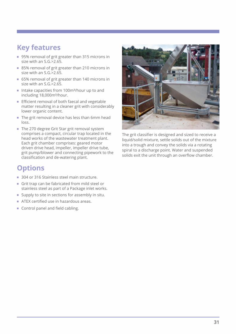
The grit classifier is designed and sized to receive a liquid/solid mixture, settle solids out of the mixture into a trough and convey the solids via a rotating spiral to a discharge point. Water and suspended solids exit the unit through an overflow chamber.
Key features ■ 95% removal of grit greater than 315 microns in
size with an S.G.>2.65. ■ 85% removal of grit greater than 210 microns in
size with an S.G.>2.65. ■ 65% removal of grit greater than 140 microns in
size with an S.G.>2.65. ■ Intake capacities from 100m³/hour up to and
including 18,000m³/hour. ■ Efficient removal of both faecal and vegetable
matter resulting in a cleaner grit with considerably lower organic content.
■ The grit removal device has less than 6mm head loss.
■ The 270 degree Grit Star grit removal system comprises a compact, circular trap located in the head works of the wastewater treatment plant. Each grit chamber comprises: geared motor driven drive head, impeller, impeller drive tube, grit pump/blower and connecting pipework to the classification and de-watering plant.
Options ■ 304 or 316 Stainless steel main structure. ■ Grit trap can be fabricated from mild steel or
stainless steel as part of a Package inlet works. ■ Supply to site in sections for assembly in situ. ■ ATEX certified use in hazardous areas. ■ Control panel and field cabling.
31

DescriptionGrit and sand are very abrasive and if not removed from the sewage flow can foul equipment and rapidly wear pumps and other plant downstream.
Sand and grit are washed into the sewers from roads and from the ground through cracks in sewers.
Grit gets carried along with the flow but if the flow of the sewage is slowed down the grit and sand will settle out.
It is important that the speed is not too slow or organic material, which should pass forward for further treatment, will also be settled out.
DM Crossflow Detritor & Grit Rake Classifier
Grit SettlementUpon entry to the Detritor Chamber the sewage flow is evenly distributed through adjustable, vertical concrete baffles (by civil contractor). Adjustable mechanism supplied by Ham Baker Adams.
The flow slows down to about 0.3m/s and the grit and sand settle to the floor of the tank. Scrapers push the material to small sumps at the side of the tank, from where it is pumped to washing equipment which removes any organic matter.
The width of the chamber is determined by the flow rate to ensure that settling velocity is achieved, i.e. when the grit falls out of suspension before the outlet weir.
The outlet weir, except at minimum flow, will usually be submerged to form a barrier to ensure that the settled grit is contained in the flat bottomed chamber.
The relatively clean grit is then deposited in skips for transportation to landfill.
32

Grit CollectorThe rotating scraper has three fabricated arms, manufactured from painted mild steel or stainless steel 316. Each arm has a number of scraper angles positioned so that the settled grit is moved spirally outwards from the centre. A bucket, fitted at the end of each arm collects the grit and transfers it to the perimeter of the tank to the washing/rake chamber.
The arms are fixed to the central drive assembly and have cantilevered, adjustable supports to ensure that the arms are level. Anti-sway bars are also included.
The drive assembly has an IP55 rated motor, with anti-condensation heaters, which provides drive through a gearbox and heavy duty drive shaft with coupling and slewring bearing. A torque limiting device is incorporated to provide protection in the event of blockage and will disconnect the drive thus preventing damage to the scraper mechanism.
The drive unit is mounted on a bridge, rated at 5kN/m2, which spans the chamber and includes hand-railing, kick plates and open mesh flooring. It can be supplied in either galvanised mild steel or stainless steel 316. The bridge allows access to the drive assembly for maintenance and lubrication. The drive is designed for easy removal if necessary.
Grit Rake ClassifierThe Grit Rake Classifier has a fabricated raking mechanism which consists of a series of scraper blades welded along the length of the assembly. The self-aligning crankshafts (primary and secondary), provided the reciprocating motion which moves the grit from the washing chamber up to the discharge point. The rake mechanism is driven by an IP55 rated motor/gearbox unit which is externally mounted for ease of access for maintenance. The assembly is fully guarded.
Organics Return Pump & Rag Screen/FilterThe Organics Return Pump has a stainless steel 316 impeller driven through a vertical extended shaft from a direct drive motor. The pump returns organic matter released from the settled grit, during washing, back to the main flow for further treatment. This is screened by a perforated plate cylindrical screen/filter.
Key Features ■ Settlement chambers can be designed from 3m to
12m diameter ■ Maximum flow, for 95% removal of grit greater
than 210 microns in size with an S.G > 2.65, range from 150 to 2700l/s
■ Grit handling rate from 0.05 to 0.95m3/hr ■ Detritor motor power rating from 0.1 to 0.75kW ■ Grit Rake Classifier motor power rating from 3.0
to 5.0kW ■ Organics Return Pump motor power rating
0.75kW.
33

Standard featuresThe Ham Baker Group offers a range of modularised scraper bridge solutions which enable us to deliver in the shortest possible lead times.
Ham Baker Group’s rotating half-bridge, three-quarter bridge and full-bridge scrapers are built to a standardised modular design. Comprising quality components and attributes such as:
■ Design to WIMES standards for primary (PST), final (FST) humus and storm tank processes.
■ A range of optional and adaptable features to accommodate particular specification requirements.
■ Drive unit speed and power to suit the required application.
■ Stainless steel submerged components as standard.
■ Optimum bridge and scraper construction for typical load conditions and tank parameters
■ Installation by our in-group experienced and certified mechanical and electrical installation teams.
■ All structures CE marked in accordance with EN1090
Rotating Settlement Tank Scrapers
Permanent or removable anti-slip flooring on bridge deck.
Fully adjustable scraper blade system complete with reversible scraper blades for improved longevity.
Automatic greasing systems for slew-ring bearing.
All electrical wiring and components included as standard.
Peripheral drive with loss of motion detection and either mechanical torque overload protection or real-time torque feedback for process optimisation.
34

Standard benefitsThe Ham Baker group of companies which include the historic Adams Hydraulics and A & J Water brands have together delivered hundreds of scraper bridges to the UK and international markets.
With each of our products and services we are proud to offer:
■ The extensive expertise and experience of our specialised team combined with our active research and development work ensures the optimum solution for every customer on every project.
■ Fast lead times thanks to our standardised modular designs, focused UK-based supply chain, and quick responding site services team.
■ Adaptable features and accessories to suit the budget and requirements of every project.
■ A complete solution including concept design support, design, manufacture, factory testing, delivery, installation, commissioning and maintenance and after-market care.
■ Design, supply and installation of all electrical components as standard.
■ Design, supply and installation of GRP ancillary components as required.
■ High quality engineering and UK-manufactured components.
35

Technical overviewWe can off er services to help defi ne the functional requirements for new equipment, such as our sludge loading data analysis service for existing assets*.
Though any tank size or specifi cation can theoretically be accommodated, the below illustrates some typical parameters of our settlement tank scraper bridges.
Typical Tank Dimensions Ø (m) 5m 15m 25m 35m 45m
Typical TankSide Wall
Depth d (m)
Typical FloorSlope O (⁰)
Half Bridge 2.0 - 3.5m 7 - 15
Three Quarter Bridge 3.0 - 3.5m 7.5
Full Bridge 2.5 - 5.0m 7.5
Typical PeripheralSpeed (m/min)
Typical Walkway Widthand Loading
Typical Sludge Loading onScraper Blades (kN/m²)
PST & Storm Tanks 1.5 - 2.1 0.6 - 1.0m 2-5KN/m² 60 - 200
FST & Humus Tanks 1.0 - 1.2 0.6 - 1.0m 2-5KN/m² 60
ØdO
36

Accessories and AdaptationsWe can offer all manner of adaptations, optimisations and accessories to suit particular site process, structural forms, maintenance or safety requirements.
A variety of options are available, such as:
Fitments for sludge blanket detection equipment, torque monitoring equipment, lifting davits, drive carriage obstruction detectors and other instrumentation or components as required.
Drive traction improvement options including: Anti-slip running surfaces, heat lamps for winter operation and loss-of-motion detector on idle wheel.
Tanks and their functional components in GRP or steel including scum boards, launders, weirs and covers.
All manner of flow-controlling baffles for optimum settling conditions including Diffuser Drums, Stamford baffles, McKinney baffles and Energy Dissipating Inlet baffles (EDIs) complete with hydraulic design and modeIIing services if required.
Winch-lifting weir and launder cleaning brush systems.
Bespoke access ladders, walkways, stairs and hand-railing to British standards.
A range of scum removal and scum concentration equipment.
37
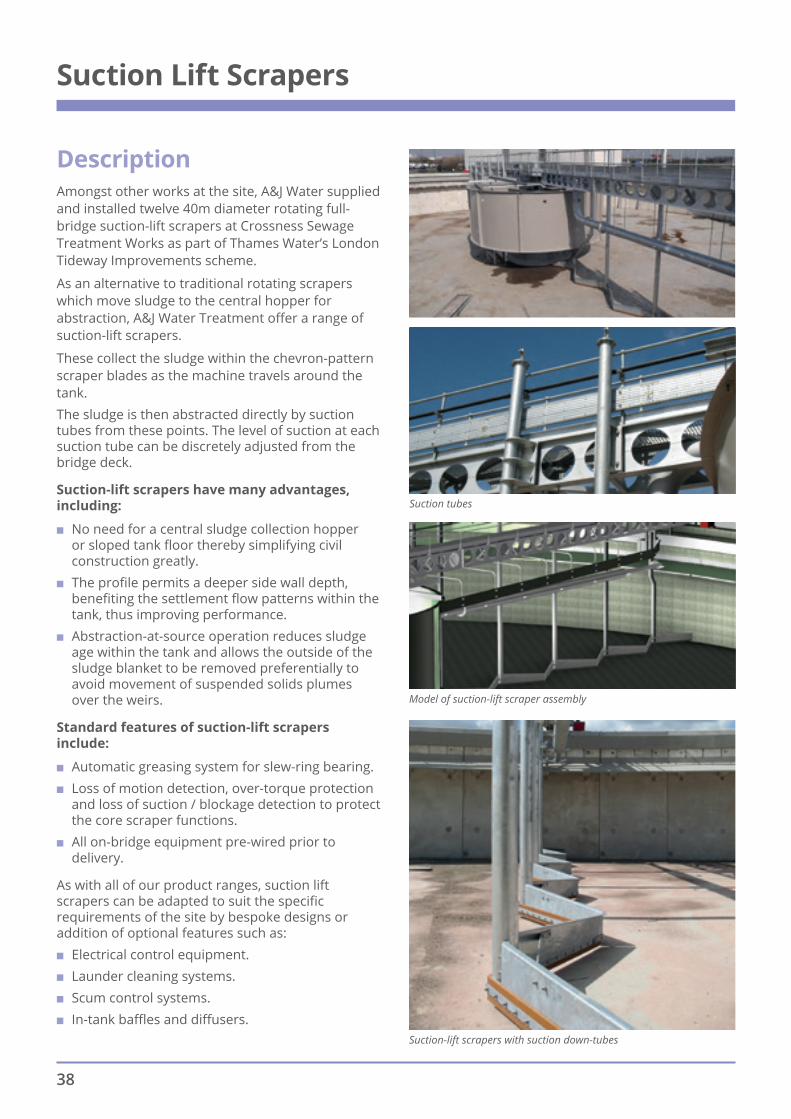
DescriptionAmongst other works at the site, A&J Water supplied and installed twelve 40m diameter rotating full-bridge suction-lift scrapers at Crossness Sewage Treatment Works as part of Thames Water’s London Tideway Improvements scheme.
As an alternative to traditional rotating scrapers which move sludge to the central hopper for abstraction, A&J Water Treatment offer a range of suction-lift scrapers.
These collect the sludge within the chevron-pattern scraper blades as the machine travels around the tank.The sludge is then abstracted directly by suction tubes from these points. The level of suction at each suction tube can be discretely adjusted from the bridge deck.
Suction-lift scrapers have many advantages, including:
■ No need for a central sludge collection hopper or sloped tank floor thereby simplifying civil construction greatly.
■ The profile permits a deeper side wall depth, benefiting the settlement flow patterns within the tank, thus improving performance.
■ Abstraction-at-source operation reduces sludge age within the tank and allows the outside of the sludge blanket to be removed preferentially to avoid movement of suspended solids plumes over the weirs.
Standard features of suction-lift scrapers include:
■ Automatic greasing system for slew-ring bearing. ■ Loss of motion detection, over-torque protection
and loss of suction / blockage detection to protect the core scraper functions.
■ All on-bridge equipment pre-wired prior to delivery.
As with all of our product ranges, suction lift scrapers can be adapted to suit the specific requirements of the site by bespoke designs or addition of optional features such as:
■ Electrical control equipment. ■ Launder cleaning systems. ■ Scum control systems. ■ In-tank baffles and diffusers.
Suction Lift Scrapers
Suction tubes
Model of suction-lift scraper assembly
Suction-lift scrapers with suction down-tubes
38

DescriptionWe have combined a retractable scum concentrator arm with our peripheral dipping scum removal device for applications where high volumes of mousse-like scum accumulates and resists withdrawal from the tank by conventional means.A typical application would be on activated sludge plants and where seasonal changes can provide high scum volumes.A suitably sized adjustable dipping scumbox is effective in removing localised scum as both head and dwell time are adjustable. For the ScumAway system, the scumbox is complemented by a retractable arm which extends across the tank radius so as to retain and concentrate the scum in the area of the scumbox.The scraper bridge carries the scumbox actuator and the mechanism which pushes the scum arm back against the tank wall enabling the rotating bridge to pass after actuating the scumbox.After the bridge passes, the scum arm slowly returns to its operating position ready for the next cycle. A demonstration of the effectiveness of the scum concentrator arm,
seen with a dipping scumbox
Model of a dipping scumbox Dipping scumbox
Dipping Scumboxes and ScumAway
39

Other Scum Removal SystemsWe have provided hundreds of scum removal devices and systems into settlement tank applications, both on new tanks and retrofit to existing scraper systems. We are experienced in all common scum removal systems, and can advise as to the most appropriate solution for any given application.
Pumped Scum RemovalThis simple scum solution consists of a bridge-mounted scumblade, a pump and scum box with adjustable weir system and low level float switch. Scum is guided towards the bridge-mounted scum box and passes over an adjustable weir into the scum box. The level is drawn down by the pumping system and the scum is removed from the box. A pipe runs along the bridge and terminates either above the surface water level inside the diffuser drum, so as to break up any scum therein, or alternately in the case of siphon-lift scrapers, within the sludge hopper so that the scum is removed with the sludge.
Rotary Scumboxes The rotary scumbox is a historically popular design due to its compact dimensions. Because of this it can easily be retrofitted to an existing settlement tank. We can also offer automated rotary scumboxes for rectangular tank scraper systems.
Siphonic Scum Removal Generally fitted to suction-lift scrapers, an adjustable weir controls the flow of scum and surface water into the scum box, from where it is recovered by the same siphonic action as is in action at the tank floor removing settled sludge. Using the function of the siphon allows scum to be removed from the tank without the installation of out-of-tank infrastructure such as reception chambers, pumps, pipes and associated electrical services as would be required for a separately pumped system, thus reducing both CAPEX and OPEX costs.
Models of a pumped scum collection box
Model and image of a typical rotary scumbox
Left: Example of a siphoned scum collection system retrofitted to an existing scraper bridge.
40

Picket Fence and WRc Thickeners for reliable sludge concentrationThe Ham Baker Group are proud to be able to offer the benefit of our decades of experience in the design, manufacture and installation of WRc Thickeners and Picket Fence Thickeners. Our past projects include varying styles and sizes of thickener from as little as 1.6m to 20m diameter, package plants (tank and thickener) and fabrication in a variety of materials such as painted or galvanised mild steel and 304, 316 and even duplex grade stainless steel.Our thickeners have been installed for operation at potable water treatment plants, wastewater works and also industrial plants, for which the process conditions can be particularly difficult. Where applicable, our designs conform to the relevant WRc guidelines to give the best possible sludge solids concentration and to reduce sludge volume, thus reducing subsequent dewatering and sludge disposal costs. Options can include inlet diffusers, launders, GRP roofs, scum control and sludge blanket monitoring, and for more process-critical applications, real-time sludge loading monitoring and feedback. We offer a full turnkey solution, this may include the design and manufacture of the process tank, thickener mechanism, access stairways and platforms, pre-wiring and pre-assembly off-site and mechanical and electrical site installation, followed by commissioning by highly trained and competent site team engineers.
Picket Fence Thickener
WRc Thickener blades
Sludge Thickeners
41
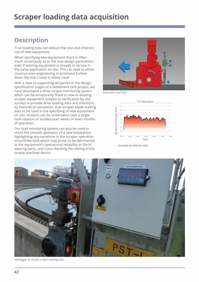
Drive with Load Cell
FST Operation
Time
Kg F
orce
at T
orqu
e Ar
m
Example of collected data
Datalogger in use for a short running trial
Description True loading data can reduce the cost and inherent risk of new equipment.When specifying new equipment there is often much uncertainty as to the true design parameters, even if existing equipment is already in service in the same application on site. This can lead to either cautious over-engineering or problems further down the line: Costly in either case! With a view to supporting all parties in the design specification stages of a settlement tank project, we have developed a drive torque monitoring system which can be temporarily fitted to new or existing scraper equipment (subject to verification by site survey) to provide drive loading data and therefore, by theoretical calculation, true scraper blade loading data to be used in the specifying of new equipment on site. Analysis can be undertaken over a single tank rotation or studied over weeks or even months of operation.Our load monitoring system can also be used to check the smooth operation of a new installation, highlighting any variations in the scraper operation around the tank which may prove to be detrimental to the equipment’s operational reliability or life of wearing parts, and cross-checking the setting of the torque overload device.
Scraper loading data acquisition
42

3D model of a large-diameter McKinney Baffle as retrofitted to a 40m final settlement tank.
Left: CFD Model of an Energy Dissipating Inlet
DescriptionThe Ham Baker Group can design, manufacture and install any manner of flow controlling baffle, diffuser or in-tank feature in GRP or steel to fulfil a project’s exact requirements.Among other flow-control features Energy Dissipating Inlets (EDI), Stamford Baffles and McKinney Baffles can be modelled and designed to optimise mixing behaviour within the settling tank to ensure settling efficiency is maximised within the constraints of the tank dimensions.
Flow Control Baffles and other Tank Accessories
43
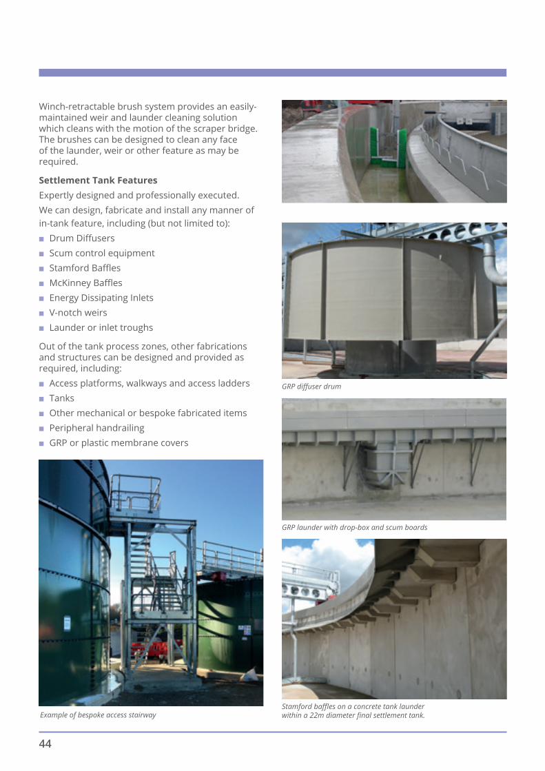
Winch-retractable brush system provides an easily-maintained weir and launder cleaning solution which cleans with the motion of the scraper bridge. The brushes can be designed to clean any face of the launder, weir or other feature as may be required.
Settlement Tank FeaturesExpertly designed and professionally executed.We can design, fabricate and install any manner of in-tank feature, including (but not limited to):
■ Drum Diffusers ■ Scum control equipment ■ Stamford Baffles ■ McKinney Baffles ■ Energy Dissipating Inlets ■ V-notch weirs ■ Launder or inlet troughs
Out of the tank process zones, other fabrications and structures can be designed and provided as required, including:
■ Access platforms, walkways and access ladders ■ Tanks ■ Other mechanical or bespoke fabricated items ■ Peripheral handrailing ■ GRP or plastic membrane covers
Stamford baffles on a concrete tank launder within a 22m diameter final settlement tank.
GRP diffuser drum
GRP launder with drop-box and scum boards
Example of bespoke access stairway
44

Scraper upgrades, retrofits and refurbishments
DescriptionIrrespective of the age or origins of the existing equipment on site, the Ham Baker Group can offer a solution.The Ham Baker Group can provide a range of servicing and renovation possibilities from inspection and condition testing of existing assets to complete over-hauls, retrofitting of our state-of the-art technologies or just a simple dash of oil if that’s all that’s required.
Possible scraper tank retro-fits may include:
■ Scum-control devices (dipping scum boxes, beach scum boxes, pumped scum removal, scum-boards, scum concentrators etc).
■ Scraper arrays (including dragged arrays). ■ Alternative process solutions for rectangular
settlement tanks i.e. Chain & Flight Scrapers. ■ Weirs, launders and baffles. ■ Weir and launder cleaning brushes. ■ Energy Dissipating Inlets, McKinney Baffles,
Stamford Baffles and other flow-control devices. ■ Instrumentation and monitoring equipment and
electrical upgrades. ■ Drive traction improvements. ■ Automatic greasing systems. ■ Best-practice health and safety equipment and
access upgrades.
Possible refurbishments/upgrades may include: ■ Drive unit refurbishment or replacement. ■ Bearing refurbishment or replacement. ■ Replacement of wearing parts (blades, brushes,
tyres, seals, slip ring contacts...)
■ Addition of condition monitoring equipment.
Retrofit of scum control systems in an existing scraper tank
Retrofit of a rotary scumbox to an existing tank
Retrofit of new scrapers and scum blade on an existing bridge
Retrofit of new GRP weirs and scum boards in an existing scraper tank
45

Description The Self-Seal distributor has a very compact gland and base flange attachment, which makes it ideal for installation where the duckfoot base is close to the top surface of the filter mediaIt is especially well suited to replacement of older types of distributor where modifications to the existing feed system would be both costly and time consuming. The centres are delivered to site, fully assembled to ensure down time on operational works are kept to a minimum.The seal between the rotating and fixed columns is achieved by means of a simple nitrile ‘V’ seal running in gunmetal gland housing.The Self-Seal is also capable of taking a direct pumped flow and like the Weir Cresset can be configured to pass split flows to achieve optimum distribution at minimum and maximum flows.
Self-seal Distributor
The Self-Seal Distributor, similar to the Cresset Distributor, can be arranged with two arms for normal flows and the remaining two arms as overflow arms for excess flows.
Key Features ■ Suitable for beds up to 40m diameter ■ Flows from 5 to 300 m3/hour ■ Cast iron centre column, crosshead and duckfoot
base for maximum life ■ Can receive pumped flows ■ Jet reaction or powered drive ■ In operation for over 50 years.
A part sectional detail drawing is illustrated here.
46

DescriptionThe success of the Cresset/Weir Cresset distributor is down largely to the Airlock Seal that is formed between the fixed outer tank and the rotating inner tank. The Airlock Seal is almost frictionless and makes the machine ideal for installation in very low hydraulic head situations whilst still maintaining the ability to achieve jet reaction.
Key Features ■ Suitable for beds up to 60m diameter ■ Flows from 3 to 1500 m3/hour ■ Cast iron centre column, crosshead and duckfoot
base for maximum life ■ ‘Airlock’ Tanks which create an almost frictionless
seal which requires a low driving head. ■ Reduced wear and extended working life, in
excess of 50 years ■ Drive and overflow (Weir Cresset) arms to give
curtain flow with spreader plates (jet reaction) or top centre nozzles (powered drive).
The Weir Cresset is simply an extension to the Standard Cresset, which gives the option of a very efficient flow split through the machine, to give optimum distribution at minimum and maximum flows.The “Weir Cresset” Distributor is similar in construction to the Cresset Distributor except that inside the revolving inner tank there are weir plates to stop the flow reaching the two overflow arms. The initial flow passes directly to the two drive arms and as the flow increases it passes to the two overflow arms over the weir, as shown above. The two overflow arms are usually larger than the two drive arms in order to give as large a volume variation as possible.Whilst recirculation is often used to maintain a constant flow through a sewage works and obviating the need for syphons, it is often found that the flow is not constant to use standard Distributors and the additional flexibility of the “Weir Cresset” is most useful.
The design of the “Weir Cresset” provides a long weir length which enables this type of distributor to pass a large increase in volume with very little increase in head.
Cresset & Weir Cresset Distributors
47

The drawing here shows a section through an overflow arm and a section through a drive arm of the Weir Overflow “Cresset” Distributor. With the four-arm machine the two drive arms are set at right angles to the two overflow arms.As the water rises in the centre of the machine it first passes into the drive arms. The drilling of these two arms is so arranged that when the inflow to the machine is down to the predetermined minimum rate, sufficient head is created on the spray holes to ensure satisfactory rotation of the machine. As the inflow increases it continues to discharge via the drive arms until it rises to the weir level when it passes into the overflow arms. Any further increase in flows is passed to these arms.
The combined drilling of the spray holes in the two sets of arms is such that the maximum head created in the centre column operating on all four arms will pass the maximum total volume with little alteration in speed.Standard Weir Overflow “Cressets” pass up to 3 x D.W.F. through the drive arms and up to 6 x D.W.F. with the overflow arms. We can also supply high rate machines for a variation in flow between maximum and minimum of up to 8/10: 1.
48

DescriptionThe paddle wheel distributor is designed to be a very low maintenance, long life distributor for use on smaller works where extended maintenance periods and high reliability are required. It also offers a number of improvements in process efficiency due to its ability to continue running at all flows, dosing the bed ‘little and often’ and providing excellent evenness of distribution. Tests have shown significant improvements in all aspects of treatment when compared with a standard syphon operated machine.The unit differs from conventional machines in that it is a paddlewheel driven distributor using open trough arms to make for minimal blocking and easy cleaning. It is constructed from corrosion resistant materials, and has a design life of 25 years.
Overhead Feed:
Key Features ■ Suitable for beds up to 12m diameter (Overhead)
and 17m diameter (Central) ■ Flows up to 6l/s (Overhead) and 30l/s (Central) ■ Low maintenance, suitable for rural sites ■ Stainless Steel trough arms with GRP V Notch
weirs to give curtain flow ■ Galvanised mild steel tank and painted to WIMES ■ GRP paddlewheel ■ Cast iron central column (Central).
Central Feed:
Paddlewheel Distributors
49

Rectangular Filter Beds Cantilever Travelling DistributorThe Ham Baker Adams range of Cantilever Travelling distributors takes all the experience of many years of manufacture and harnesses it with more up to date materials in the form of stainless steel and GRP (glass reinforced plastic), which leads to a very clean and low maintenance solution.Our in house engineering facility can modify the standard design to fit most existing installations.
Key Features ■ Suitable for beds up to 50m span (Overhead) ■ Flows up to 325l/s per machine ■ Galvanised tubular single or twin arms with top
centre nozzles ensure arms are always full to enhance the overall balancing of the machine and give curtain flow distribution
■ GRP Syphon and tanks (Other options available) ■ Stainless steel chassis and main frame (Other
options available) ■ Power systems include Enclosed Conductor
System, C Rail Festoon, Catenary Wire Festoon, Drum Reeling Cables or winch hauled
■ Rails can be positioned either on the top of the central feed channel walls or at the lower media coping level
■ Single flange tapered wheels which are inherently self-centring in operation therefore removes the possibility of motion crabbing
■ Intelligent local control panel and power distribution positioned at the end of the filter bed in an existing drive house building/kiosk with wireless communications to remote panel term on the distributor. Alternatively two panels can be used with the first of which is predominately power distribution mounted at the end of the filter bed or in an existing drive house building/kiosk with the second panel mounted on the distributor.
Travelling Distributor
If two are more travelling distributors are installed we can utilise the enclosed conductor system which can run the full length of the filter bed. This method of electrical feed offers the ability to be able to cover 90% of the total filter bed with only one machine, should circumstances arise where one or more machines need to be taken out of operation for maintenance purposes.Our methodology for start/stop/turnaround of the machines is by means of an inverter drive to control each of the machines individually, which allows us to programme a nicely profiled deceleration/rest before turnaround and then a similarly profiled acceleration to allow the machine to get back up to speed gradually.This all helps to minimise the sudden mechanical shock loading on the machines, which in turn protects the structure, wheels and suspension etc. from any exacerbated loads cause by excessive arm end movements being transmitted back to the main structureTo enable maximum bed coverage the machines incorporate an anti-collision mechanism which enables the designated travel of each machine to be configured marginally over its third proportion.In the event that two machines arrive at the turn around point at the same time, we have incorporated an infra-red sensor system to initiate immediate turn around. This method allows for full bed coverage and no dry spots at the turnaround point of the distributors.When large variations in flow rates are encountered, twin arm units can be supplied to ensure that even under minimum flow conditions satisfactory distribution can be achieved across the full width of the filter bed.
50

Control panel with Beacon stack
Emergency stop button with lifting davit positioned for gearbox/motor maintenance.
Rails positioned at media coping level and typical enclosed conductor system
BenefitsA cantilever distributor spans the width of the filters at both sides of the feed channel, a coverage for which two bridge type machines would be required and as such needs only half the amount of rails, carriage wheels and bearings, which would be required for a bridge type distributor giving similar coverage. This can result in a considerable saving not only in initial expenditure but also in the cost of subsequent maintenance. Compared with rope hauled type machines each distributor carries its own drive unit, therefore items such as winding gear and motor room, rope guiding rollers and their supporting plinths, limit and slack rope switched are not required.
Flanged taper wheel design – Rails positioned on the central channel
51

With each of our products and services we are proud to offer:
■ The extensive expertise and experience of our specialised team combined with our active research and development work ensures the optimum solution for every customer on every project.
■ Fast lead times thanks to our standardised modular designs, focused UK-based supply chain, and quick responding site services team.
■ Adaptable features and accessories to suit the budget and requirements of every project.
■ A complete solution including concept design support, design, manufacture, factory testing, delivery, installation, commissioning and maintenance and after-market care.
■ Design, supply and installation of all electrical components as standard.
■ Design, supply and installation of GRP ancillary components as required.
■ High quality engineering and UK-manufactured components.
BEFORE
AFTER
The Ham Baker Group of Companies, which includes the historic Adams Hydraulics and A & J Water brands, have together delivered innovative syphon solutions for the UK and international markets.
Rotary Distributor Siphons
52

Advantages BenefitsPlastic syphon dome Lightweight dome – reduced manual handling weight.
Non-metal – no corrosion.High density plastic – stronger, damage resistant.
Removable syphon dome weights Reduced manual handling weight.
Ball valve cleaning points Quick and easy cleaning of air pipes on syphons.Reduces need to lift syphon domes for cleaning air pipes.
Union joints Remove air pipes – reduced manual handling weight, easy clean of air pipes, allow removal for replacement.
Syphon plate Allows removal of air pipework from syphon dome.Easy replacement of all air pipework.
Adjustable studs Allow adjustment of syphon dome height to optimise syphon dome performance.
Improved syphon operation Reliable syphon operation and improved distributor process.
Improved safety Reduce risk of injury to site operators.Syphon replacement service and commissioning
Hassle-free replacement of old syphons.New syphons optimised to suit site conditions.
The Ham Baker Group offers a range of plastic syphons for rotary distributors for improved distributor operation and enhanced health and safety benefits.
1
6
5
2
3
4
Adjustable studs for siphon dome5Ball valves to improve cleaning of break pipe2
Removable weights with handles – safer manual handling6Light weight plastic siphon dome –
Safer manual handling3
Union Joints on air pipework. Easy removal for cleaning if required1 Removable air pipe assembly for
easy replacement4
53

54
Installation, Maintenance and Refurbishment of all makes and models of process equipment
■ Safeguard your capital investment ■ Reduce your overall operating costs ■ Maintain the performance of your capital
equipment ■ Improve your planning and financial control
We offer a full installation and commissioning service to ensure that all installations are highly accurate and free from distortions. This allows our customers to experience the true durability, strength, and long-term performance of our products.
InstallationSite Surveys – To provide accurate specification of the most appropriate and cost effective equipment.
Installation and Commissioning – Ensure the correct installation and commissioning of all process equipment products including:
■ Screens ■ Screens Handling ■ Grit Plant ■ Scrapers ■ Distributors ■ Syphons
Project Management – Full project management from specification to commissioning.
Site Supervision – Worldwide supervision of the client’s own labour to ensure correct installation of equipment.
MaintenanceRisk Assessment – Ensure compliance with Health and Safety Legislation and suitable safety measures are put in place for ongoing maintenance.
Service Programmes – A range of service programmes designed to suit your specific requirements.
Breakdown – An emergency service to deal with an unexpected mechanical breakdown of equipment.
Of course, once installed we also understand that correct maintenance can further optimise our customers’ initial investment, minimise their overall
operating costs, and ensure correct long-term performance; which is why we also offer tailored maintenance programmes which are designed to specifically meet our customers’ operational and service needs.
We have products still in practical working order after over 100 years of continuous service, as well as an archive of project designs and records from the very earliest days of the Company; all of which means that we are able to supply the correct spares and services to equipment of all ages.
Our staff are all trained to the highest level, with all relevant certification, and all of our services are covered by our BS EN ISO 9001:2008 quality certification.
RefurbishmentSite Surveys – To ensure we specify the most appropriate and cost effective refurbishment of existing equipment. Refurbishment – We have an extensive archive of information going back over many years so we can ensure that all refurbishment of process equipment is carried out correctly using OEM parts.
Project Management – Full project management from specification to commissioning of refurbished equipment. Ancillary Equipment – The mechanical refurbishment of ancillary equipment on treatment plants and other sites.
SparesFastrack – A range of standard spares for an emergency breakdown despatched within 48 hours.
HB Certified – Quality spares manufactured under our BS EN ISO 9001:2008 system to guarantee the continued long-term performance of your equipment. Using our project records which go back over many years we can help to ensure that the correct spare is supplied.
From enquiry to commissioning, our comprehensive service includes:
New Product Installation ■ On site services. ■ Installation and commissioning ■ Site Survey ■ In-house CAD, CNC and fabrication ■ ISO9001 2008.
Services

HAMBAKER GROUP
ISO 14064-1
certifi edorganisation
A & J Water TreatmentAdams Hydraulics
AutodamCoes GRP
FSE InstallationsHam Baker Adams
Ham Baker Control SystemsHam Baker Pumps
Ham Baker RenewablesHi-Bar
Industrial PenstocksIndustrial Pipelines
Industrial ValvesIntovalve
IVL Flow ControlKempster Valves & Engineering
Three Star Environmental
The Ham Baker Group companies
Ham Baker Group is a trading name of F. J. Holdings LtdCompany Registration No. 4878424
Garner Street Business ParkGarner Street
Etruria Stoke-on-Trent
ST4 7BH
t: +44 (0) 1782 202300f: +44 (0) 1782 203649
www.hambakergroup.com