Embed Size (px)
Citation preview

1
Introduction In this laboratory case study we were assigned to research curved garden walls. The main object was to investigate what effect the curvature of the curved wall has on their ability to take lateral wind loading and to determine when the wall should be designed as a panel or when arching action can be taken into account. In simplifying the problem we assumed; 1that a simple support was provided on the bottom and two sides of the wall, 2that the material has no tensile strength, 3that the effective bearing stress is enabled over one tenth of the wall thickness, and 4that flexural design strengths for the masonry are the same as those provided for planar panels, and 5the wall has sufficient thickness such that deflection can be ignored. It should be noted that forces acting on the concave face of the wall, which cannot develop any arch action, will probably be more critical than those acting on the convex face.
Technical Review With walls of small axial loading which are built between supports, the method of design is based on the assumption that a horizontal arch is developed within the thickness of the wall. Horizontal arching is assessed based on the lateral loading, the compressive strength of the masonry and effects of the joints. Equilibrium of Shell Structures – Jacques Heyman ‘The stability of a masonry structure will be assured if it can be demonstrated that there is at least one way in which the applied loads can be transmitted to the foundations by a set of forces lying wholly within the masonry’ Structural Masonry Designers’ Manual 2nd Edition – W.G. Curtin ‘Unlike vertical arching, which is an inherent property of an axially loaded wall, horizontal arching has to be assessed on the basis of the applied lateral loading, the compressive strength of the masonry, the effectiveness of the junction between the wall and the supports’ ‘The code recommends that, the mortar used for free standing walls should not be less than mortar designation (iii). In addition, it recommends limiting the height of a free standing wall to 12 times the effective thickness.’ BS 5628-1: 2005 Cl. 32.4.4 ‘For walls having a length to thickness ratio of 25 or less, the deflection under lateral load can be ignored. For other walls, allowance should be made’ ‘Provided that the junction between the masonry and the support is solidly filled with mortar, the maximum design arch thrust per unit width of wall may be assumed to be:
2
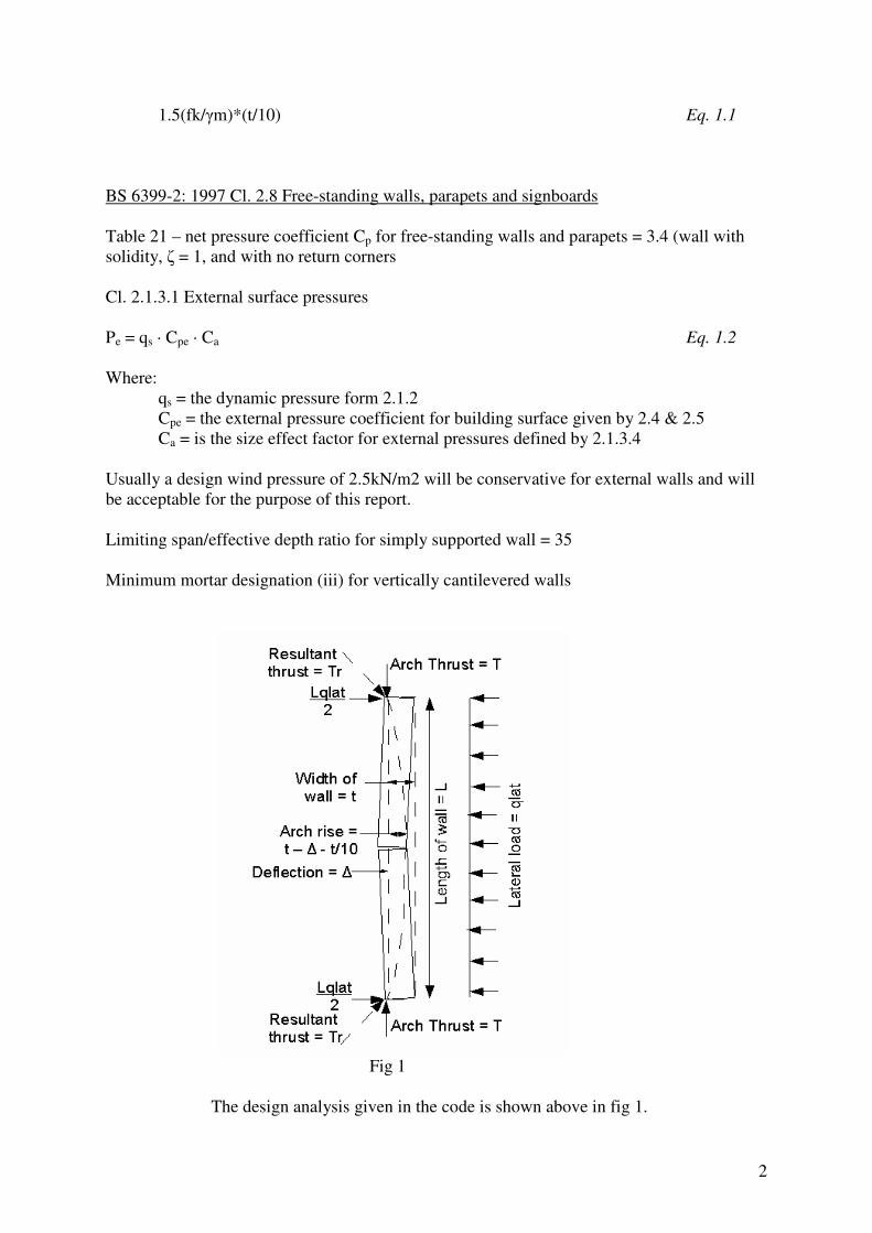
1.5(fk/�m)*(t/10) Eq. 1.1 BS 6399-2: 1997 Cl. 2.8 Free-standing walls, parapets and signboards Table 21 – net pressure coefficient Cp for free-standing walls and parapets = 3.4 (wall with solidity, � = 1, and with no return corners Cl. 2.1.3.1 External surface pressures Pe = qs · Cpe · Ca Eq. 1.2 Where: qs = the dynamic pressure form 2.1.2 Cpe = the external pressure coefficient for building surface given by 2.4 & 2.5 Ca = is the size effect factor for external pressures defined by 2.1.3.4 Usually a design wind pressure of 2.5kN/m2 will be conservative for external walls and will be acceptable for the purpose of this report. Limiting span/effective depth ratio for simply supported wall = 35 Minimum mortar designation (iii) for vertically cantilevered walls
Fig 1 The design analysis given in the code is shown above in fig 1.

3
If the ratio of length to thickness is less than 25, the deflection under lateral load can be ignored.
And therefore qlat = Eq. 1.3
Where: qlat = design lateral strength per unit area of wall t = thickness L = length of wall
fk = compressive strength of masonry �m = partial factor of safety for material strength
To find the value for the arch Thrust T, equation 2 was taken from Structural Masonry Designers’ Manual 2nd Edition – W.G. Curtin.
Eq. 1.4
In the first excel spreadsheet the variable chosen was �, the angle subtended by the arch. This meant that the curved length of the wall increased as � increased. Using the equations in the appendix the Total Resultant stress was calculated and therefore this indicated whether the wall was to be designed as a panel or an arch when it exceeded the allowable value of stress of 4.2 N/mm2. In the second excel spreadsheet the variable chosen was �. Again the same equations were used to calculate the compressive strength for each value of �. It is shown clear where it has failed and where it was satisfactory using a Pmax of 541.8 kN

4
Design for Bending Moments The design bending moments vary with the design load, the vertical and horizontal spans, the orthogonal ratio �, and the relevant design bending moment coefficient �. The Structural Masonry Designers Manual gives the following equation for the applied bending moment in the horizontal direction. MA = � · Wk · �m · L2 Eq. 1.5 � = bending moment coefficient from BS 5628-1: table 8 (see appendix) �m = partial factor of safety for the material L = length of wall Wk = applied wind load per square metre The orthogonal ratio � is obtained from values fkxparallel and fkxperpendicular given in BS 5628: table 3 (see appendix) The above formulae are presented for panel walls however the bending moment will be very similar as the inherent properties of the material, i.e. fkxparallel and fkxperpendicular are the same. Therefore the moment of resistance is as follows. MR = Eq. 1.6
It should be noted that the self weight of the material for all of the above calculations has been neglected providing a conservative value for the moment of resistance.

5
Conclusions:
• If the material has zero tensile strength, the designer may only take arching action into account when the resultant compression force lies within the middle third of the section.
• As curvature, k�0 the theoretical internal arching force required for equilibrium
increases exponentially. In reality only an area of t/10 can be assumed to be activated as the wall deflects. Therefore when the allowable bearing stress at any cross section is exceeded the wall must be designed as a panel.
• It was noted in the excel spread sheet that when the subtended angle reached 60
degrees, the lateral thrust began to decrease. This suggests that a full semi-circular arch is more suitable when providing resistance to lateral thrust is a problem.
• The theoretical model presented in the Structural Masonry Designers’ Manual (fig 1)
is conservatively applicable to curved walls with length thickness ratio of less than 25 and whose resultant force at any cross section lies within the middle third of the section.
• The type, location, and stiffness of supports have large influence on the resultant
forces in the arch.
• In answering the question of when to design a curved wall as a panel or an arch, a reasonable answer seems to be; when the resultant force at mid-span exceeds the bearing force acting over an area of t/10 – the wall should be designed as a panel with maximum arch thrust given by Eq. 1.1 above, otherwise further arching action may be taken into account.

6
Appendix A

7
Middle Third Rule: The total stress at any cross section is: Eq. 1.7 Z, for a regular cross section = bd2/6 and A = bd. The limit for no tension: Eq. 1.8 Therefore: Eq. 1.9
Therefore: Eq. 1.10 Therefore for the whole cross section emax = Eq. 1.11

8
DETERMINE THE MAXIMUM FORCE AT MID-SPAN: Assuming: 1stiff restraints are provided perpendicular to curved face, 2the deflection is approximately zero, 3the resultant force at any cross section in the arch lies within the middle third, and 4the width of bearing is , we get the following loading diagram:
Cutting the arch at mid-span we get the following free body diagram:
Summing the moments about C: Therefore: Eq. 1.12 P = Eq. 1.13
P
L/2
Tmax
qlat/2
y
C
qlat
qlat/2 qlat/2
qlat = Wk · L
Lmax = t · 25
t
Line of arch rise
Tmax Tmax Ycent
Arch rise y: = Ycent -
�
�
Tmax
Centroidal Axis
�
�
�
�
Centroidal axis
�
�
9
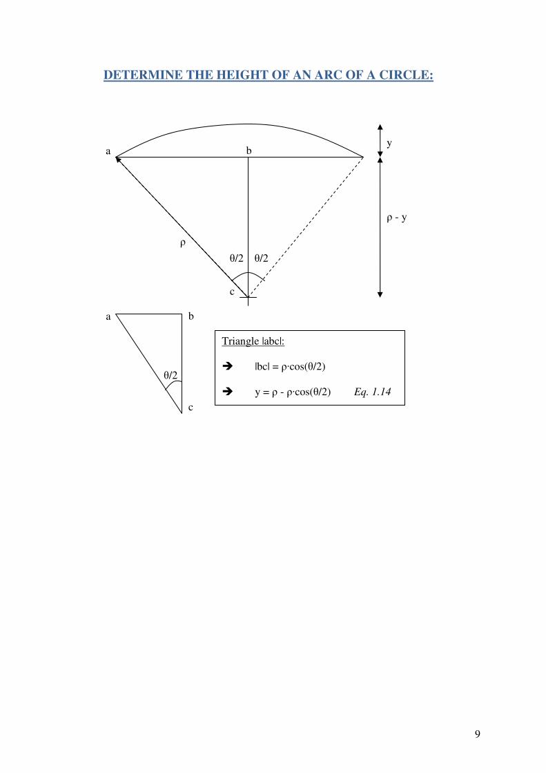
�/2 �/2 �
� - y
y a
c
b
b
c
a
Triangle |abc|: � |bc| = ��cos(�/2) � y = � - ��cos(�/2) Eq. 1.14
�/2
DETERMINE THE HEIGHT OF AN ARC OF A CIRCLE:

10
SPREAD SHEET No.1 – Curve Length Stress Relationship Variable = �.
• S = curved length (m) S = θ×R where R = �
• qlat (kN)
klat WShq ××=
• Y (m) arch height
���
����
���
���
�×−=2
cosθρρY
• X (m) length of arch in the x-direction
��
���
�××=2
cos2θρX
• R Lateral (kN)
2latq
R =
• T Thrust (kN)
Taking moments about the centre line
( )
8
8
84
84
4222
2
2
22
22
××
=�
×=
×−×=
×+=×
��
���
� ××+×=××
YXq
T
XqTY
Xq
XqTY
XqTY
Xq
XXqYT
XXq
lat
lat
latlat
latlat
latlat

11
• Total Result Tr (kN)
Tr ( )22 RT +=
• Total T (N/mm2)
310−××
=th
TT r
�
�
�
�
�
�
�
�
�
�������SHEET������ �����������������������������

12
Variable = �
• Y (m) Arch Height
( )2
2
2��
���
�+−= LY ρρ
• � (radians)
Y
L−
=ρ
θ
• S (m)
S = θ×R where R = �
• qlat (kN)
klat WShq ××=
• R Lateral (kN)
2latq
R =
• T Thrust (kN) Minimum arch Thrust
Taking moments about centre C
min2 2 15 2 4lat latq qL t L
T Y δ� �× = + − + ×� �� �
Because 252L� can be assumed to be zero
min2 15 8lat latq L q Lt
T Y× ×� �= + +� �
� �

13
min2 8
15
lat latq L q L
Tt
Y
× ×−=
+
min
3
815
latq LT
tY
× ×� =
� �+� �� �
• Tr Resultant Thrust (kN)
22 TRTr +=
• Ts Resultant Stress
310
10
−××
=t
h
TT r
s
• P Compressive Strength (kN)
15t
Y
qP lat
−=

14
� � ��������������Resistance������� �� ����� ���������������
Free standing walls may be externally boundary walls, parapet walls or internal walls where no restraint is provided to the top or sides of the wall. They are designed as vertical cantilevers, allowance being made for the stability moment due to the self weight of the wall1. The centroid of curved masonry can be found once the radius of the masonry is known as well as the angle the end of the wall makes with the y-axis,
Once the centroid of the masonry is found it is used as the point for the vertical point load caused by the self weight of the masonry, Gk. For straight free standing masonry, MR , the moment resistance to overturning is given by:
As we are dealing with curved masonry the radius of the masonry as well as the angle subtended must be taken into account. When the radius of the masonry is multiplied by the angle subtended this gives us the value S, which is then multiplied by the self weight of the masonry to give us Gk . This is then multiplied by the distance to the centroid to give us our final value for MR

15
��� ������ Structural Masonry Designers’ Manual – Curtain et al Equilibrium of Shell Structures – Jacques Heyman BS 5628-1: 2005 – Code of Practice for Structural Use of Unreinforced Masonry BS 6399-2: 1997 – Code of Practice of Wind Loading on Buildings Structural Engineers Pocket Book – Fiona Cobb