Embed Size (px)
Citation preview
34-1
GROUP 34
REAR SUSPENSIONCONTENTS
GENERAL DESCRIPTION. . . . . . . . . 34-2
REAR SUSPENSION DIAGNOSIS . . 34-3INTRODUCTION TO REAR SUSPENSION DIAGNOSIS. . . . . . . 34-3REAR SUSPENSION DIAGNOSTIC TROUBLESHOOTING STRATEGY . . . . . . 34-3SYMPTOM CHART. . . . . . . . . . . . . . . . . . . 34-4SYMPTOM PROCEDURES . . . . . . . . . . . . 34-4
SPECIAL TOOLS. . . . . . . . . . . . . . . . 34-5
ON-VEHICLE SERVICE. . . . . . . . . . . 34-6REAR WHEEL ALIGNMENT CHECK AND ADJUSTMENT . . . . . . . . . . . . . . . . . . 34-6BALL JOINT DUST COVER INSPECTION . . . . . . . . . . . . . . . . . . . . . . . 34-7
REAR SUSPENSION ASSEMBLY . . 34-8REMOVAL AND INSTALLATION . . . . . . . . 34-8
UPPER ARM ASSEMBLY . . . . . . . . . 34-10REMOVAL AND INSTALLATION . . . . . . . . 34-10INSPECTION . . . . . . . . . . . . . . . . . . . . . . . 34-11UPPER ARM BALL JOINT DUST COVER REPLACEMENT. . . . . . . . . 34-12
TRAILING ARM . . . . . . . . . . . . . . . . . 34-13
REMOVAL AND INSTALLATION . . . . . . . . 34-13INSPECTION. . . . . . . . . . . . . . . . . . . . . . . . 34-14TRAILING ARM BALL JOINT DUST COVER REPLACEMENT . . . . . . . . . 34-15
LOWER ARM ASSEMBLY AND ASSIST LINK . . . . . . . . . . . . . . . . . . . 34-16
REMOVAL AND INSTALLATION . . . . . . . . 34-16INSPECTION. . . . . . . . . . . . . . . . . . . . . . . . 34-18ASSIST LINK BALL JOINT DUST COVER REPLACEMENT . . . . . . . . . 34-20
SHOCK ABSORBER ASSEMBLY. . . 34-20REMOVAL AND INSTALLATION . . . . . . . . 34-20DISASSEMBLY AND ASSEMBLY . . . . . . . 34-21
STABILIZER BAR. . . . . . . . . . . . . . . . 34-25REMOVAL AND INSTALLATION . . . . . . . . 34-25INSPECTION. . . . . . . . . . . . . . . . . . . . . . . . 34-26STABILIZER BAR LINK BALL JOINT DUST COVER REPLACEMENT . . . . . . . . . 34-27
SPECIFICATIONS . . . . . . . . . . . . . . . 34-28FASTENER TIGHTENING SPECIFICATIONS. . . . . . . . . . . . . . . . . . . . 34-28GENERAL SPECIFICATIONS . . . . . . . . . . 34-28SERVICE SPECIFICATIONS . . . . . . . . . . . 34-29
GENERAL DESCRIPTIONREAR SUSPENSION34-2
GENERAL DESCRIPTIONM1341000100579
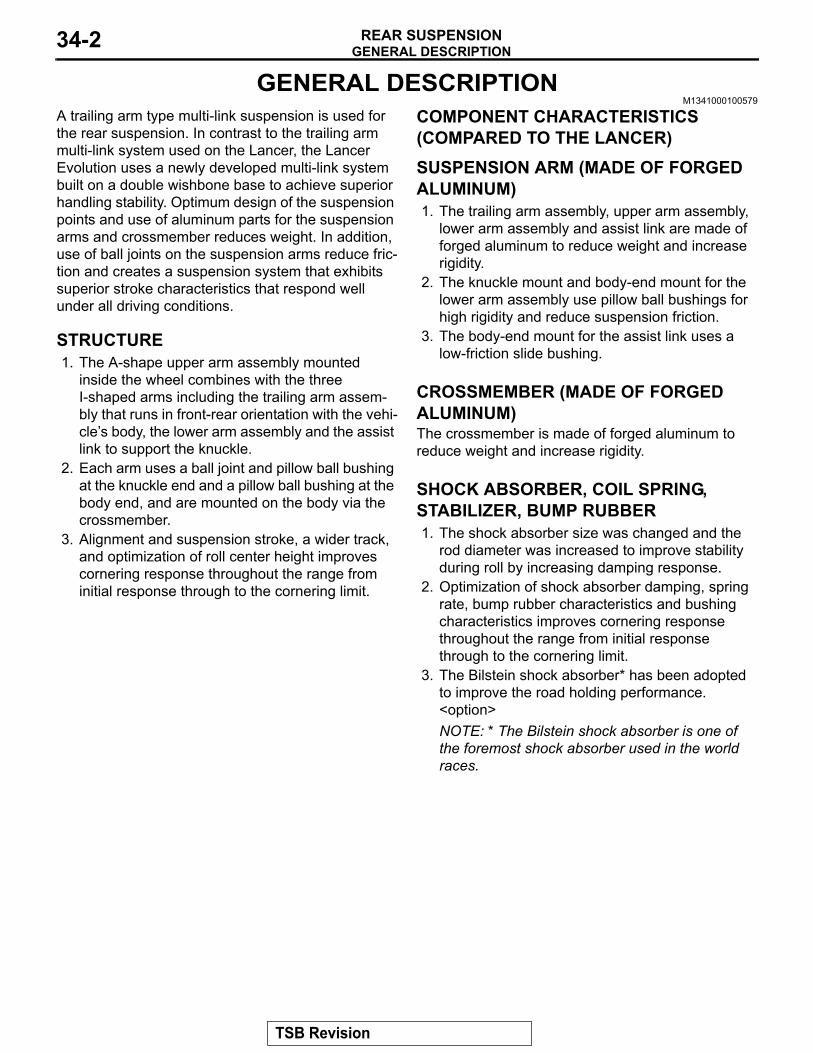
A trailing arm type multi-link suspension is used for the rear suspension. In contrast to the trailing arm multi-link system used on the Lancer, the Lancer Evolution uses a newly developed multi-link system built on a double wishbone base to achieve superior handling stability. Optimum design of the suspension points and use of aluminum parts for the suspension arms and crossmember reduces weight. In addition, use of ball joints on the suspension arms reduce fric-tion and creates a suspension system that exhibits superior stroke characteristics that respond well under all driving conditions.
STRUCTURE1. The A-shape upper arm assembly mounted
inside the wheel combines with the three I-shaped arms including the trailing arm assem-bly that runs in front-rear orientation with the vehi-cle’s body, the lower arm assembly and the assist link to support the knuckle.
2. Each arm uses a ball joint and pillow ball bushing at the knuckle end and a pillow ball bushing at the body end, and are mounted on the body via the crossmember.
3. Alignment and suspension stroke, a wider track, and optimization of roll center height improves cornering response throughout the range from initial response through to the cornering limit.
COMPONENT CHARACTERISTICS (COMPARED TO THE LANCER).
SUSPENSION ARM (MADE OF FORGED ALUMINUM)1. The trailing arm assembly, upper arm assembly,
lower arm assembly and assist link are made of forged aluminum to reduce weight and increase rigidity.
2. The knuckle mount and body-end mount for the lower arm assembly use pillow ball bushings for high rigidity and reduce suspension friction.
3. The body-end mount for the assist link uses a low-friction slide bushing.
.
CROSSMEMBER (MADE OF FORGED ALUMINUM)The crossmember is made of forged aluminum to reduce weight and increase rigidity..
SHOCK ABSORBER, COIL SPRING, STABILIZER, BUMP RUBBER1. The shock absorber size was changed and the
rod diameter was increased to improve stability during roll by increasing damping response.
2. Optimization of shock absorber damping, spring rate, bump rubber characteristics and bushing characteristics improves cornering response throughout the range from initial response through to the cornering limit.
3. The Bilstein shock absorber* has been adopted to improve the road holding performance. <option>NOTE: * The Bilstein shock absorber is one of the foremost shock absorber used in the world races.
TSB Revision
REAR SUSPENSION DIAGNOSISREAR SUSPENSION 34-3
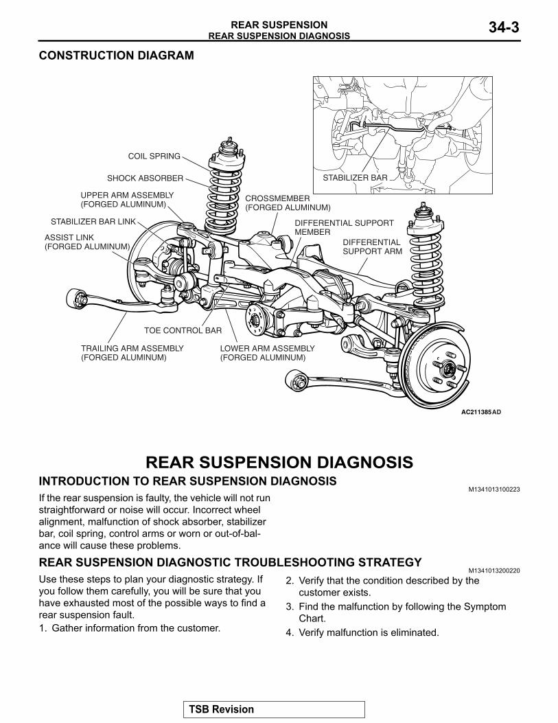
CONSTRUCTION DIAGRAM
AC211385AD
SHOCK ABSORBER
TOE CONTROL BAR
COIL SPRING
CROSSMEMBER(FORGED ALUMINUM)
LOWER ARM ASSEMBLY(FORGED ALUMINUM)
TRAILING ARM ASSEMBLY(FORGED ALUMINUM)
UPPER ARM ASSEMBLY(FORGED ALUMINUM)
DIFFERENTIAL SUPPORT MEMBER
DIFFERENTIAL SUPPORT ARM
STABILIZER BAR
ASSIST LINK(FORGED ALUMINUM)
STABILIZER BAR LINK
REAR SUSPENSION DIAGNOSISINTRODUCTION TO REAR SUSPENSION DIAGNOSIS
M1341013100223If the rear suspension is faulty, the vehicle will not run straightforward or noise will occur. Incorrect wheel alignment, malfunction of shock absorber, stabilizer bar, coil spring, control arms or worn or out-of-bal-ance will cause these problems.
REAR SUSPENSION DIAGNOSTIC TROUBLESHOOTING STRATEGYM1341013200220
Use these steps to plan your diagnostic strategy. If you follow them carefully, you will be sure that you have exhausted most of the possible ways to find a rear suspension fault.1. Gather information from the customer.
2. Verify that the condition described by the customer exists.
3. Find the malfunction by following the Symptom Chart.
4. Verify malfunction is eliminated.
TSB Revision
REAR SUSPENSION DIAGNOSISREAR SUSPENSION34-4
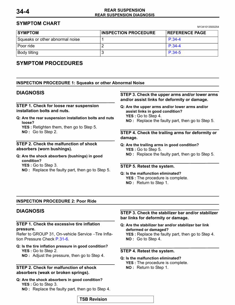
SYMPTOM CHARTM1341013500254
SYMPTOM INSPECTION PROCEDURE REFERENCE PAGESqueaks or other abnormal noise 1 P.34-4Poor ride 2 P.34-4Body tilting 3 P.34-5
SYMPTOM PROCEDURES
INSPECTION PROCEDURE 1: Squeaks or other Abnormal Noise
DIAGNOSIS
STEP 1. Check for loose rear suspension installation bolts and nuts.Q: Are the rear suspension installation bolts and nuts
loose?YES : Retighten them, then go to Step 5.NO : Go to Step 2.
STEP 2. Check the malfunction of shock absorbers (worn bushings).Q: Are the shock absorbers (bushings) in good
condition?YES : Go to Step 3.NO : Replace the faulty part, then go to Step 5.
STEP 3. Check the upper arms and/or lower arms and/or assist links for deformity or damage.Q: Are the upper arms and/or lower arms and/or
assist links in good condition?YES : Go to Step 4.NO : Replace the faulty part, then go to Step 5.
STEP 4. Check the trailing arms for deformity or damage.Q: Are the trailing arms in good condition?
YES : Go to Step 5.NO : Replace the faulty part, then go to Step 5.
STEP 5. Retest the system.Q: Is the malfunction eliminated?
YES : The procedure is complete.NO : Return to Step 1.
INSPECTION PROCEDURE 2: Poor Ride
DIAGNOSIS
STEP 1. Check the excessive tire inflation pressure.Refer to GROUP 31, On-vehicle Service − Tire Infla-tion Pressure Check P.31-6.
Q: Is the tire inflation pressure in good condition?YES : Go to Step 2.NO : Adjust the pressure, then go to Step 4.
STEP 2. Check for malfunction of shock absorbers (weak or broken springs).Q: Are the shock absorbers in good condition?
YES : Go to Step 3.NO : Replace the faulty part, then go to Step 4.
STEP 3. Check the stabilizer bar and/or stabilizer bar links for deformity or damage.Q: Are the stabilizer bar and/or stabilizer bar link
deformed or damaged?YES : Replace the faulty part, then go to Step 4.NO : Go to Step 4.
STEP 4. Retest the system.Q: Is the malfunction eliminated?
YES : The procedure is complete.NO : Return to Step 1.
TSB Revision
SPECIAL TOOLSREAR SUSPENSION 34-5
INSPECTION PROCEDURE 3: Body Tilting
DIAGNOSIS
STEP 1. Check for weak or deteriorated bushings.Q: Are the bushings in good condition?
YES : Go to Step 2.NO : Replace the faulty part, then go to Step 5.
STEP 2. Check for weak or broken springs.Q: Are the springs in good condition?
YES : Go to Step 3.NO : Replace the faulty part, then go to Step 5.
STEP 3. Check the upper arms and/or lower arms and/or assist links for deformity or damage.Q: Are the upper arms and/or lower arms and/or
assist links deformed or damaged?YES : Replace the faulty part, then go to Step 5.NO : Go to Step 4.
STEP 4. Check the trailing arms for deformity or damage.Q: Are the trailing arms deformed or damaged?
YES : Replace the faulty part, then go to Step 5.NO : Go to Step 5.
STEP 5. Retest the system.Q: Is the malfunction eliminated?
YES : The procedure is complete.NO : Return to Step 1.
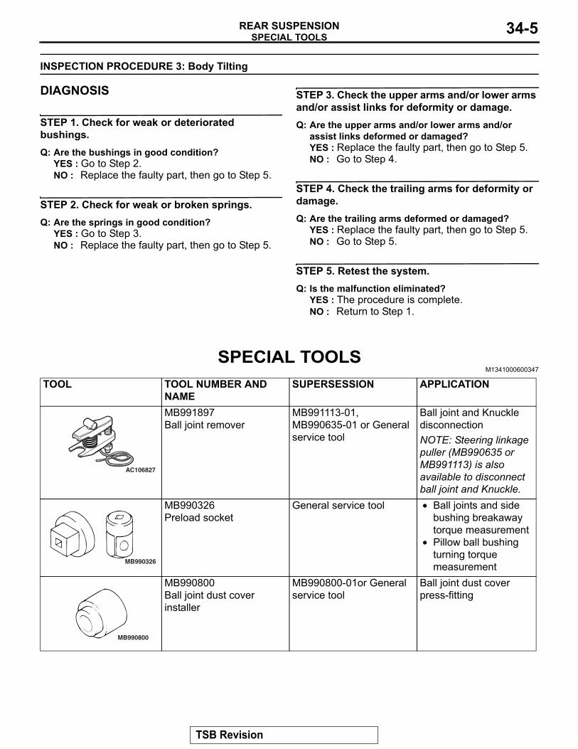
SPECIAL TOOLSM1341000600347
TOOL TOOL NUMBER AND NAME
SUPERSESSION APPLICATION
AC106827
MB991897Ball joint remover
MB991113-01, MB990635-01 or General service tool
Ball joint and Knuckle disconnectionNOTE: Steering linkage puller (MB990635 or MB991113) is also available to disconnect ball joint and Knuckle.
MB990326
MB990326Preload socket
General service tool • Ball joints and side bushing breakaway torque measurement
• Pillow ball bushing turning torque measurement
MB990800
MB990800Ball joint dust cover installer
MB990800-01or General service tool
Ball joint dust cover press-fitting
TSB Revision
ON-VEHICLE SERVICEREAR SUSPENSION34-6
MB991237
A
B
ON-VEHICLE SERVICEREAR WHEEL ALIGNMENT CHECK AND ADJUSTMENT
M1341011000554The rear suspension, wheels and tires should be serviced to
normal condition prior to measurement of wheel alignment.1. Measure the wheel alignment with the vehicle parked on a
level surface.
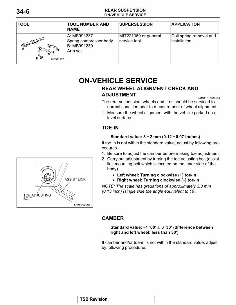
TOE-IN.
Standard value: 3 ± 2 mm (0.12 ± 0.07 inches)It toe-in is not within the standard value, adjust by following pro-cedures.1. Be sure to adjust the camber before making toe adjustment.
AC211953
TOE ADJUSTINGBOLT
ASSIST LINK
AB
2. Carry out adjustment by turning the toe adjusting bolt (assist link mounting bolt which is located on the inner side of the body).
• Left wheel: Turning clockwise (+) toe-in• Right wheel: Turning clockwise (− ) toe-in
NOTE: The scale has gradations of approximately 3.3 mm (0.13 inch) (single side toe angle equivalent to 19’).
CAMBER.
Standard value: − 1° 00’ ± 0° 30’ (difference between right and left wheel: less than 30’)
.
If camber and/or toe-in is not within the standard value, adjust by following procedures.
A: MB991237Spring compressor bodyB: MB991239Arm set
MIT221369 or general service tool
Coil spring removal and installation
TOOL TOOL NUMBER AND NAME
SUPERSESSION APPLICATION
TSB Revision
ON-VEHICLE SERVICEREAR SUSPENSION 34-7
AC211954AC
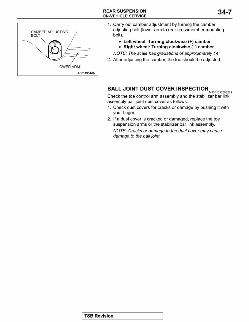
CAMBER ADJUSTING BOLT
LOWER ARM
1. Carry out camber adjustment by turning the camber adjusting bolt (lower arm to rear crossmember mounting bolt).
• Left wheel: Turning clockwise (+) camber• Right wheel: Turning clockwise (− ) camber
NOTE: The scale has gradations of approximately 14’2. After adjusting the camber, the toe should be adjusted.
BALL JOINT DUST COVER INSPECTIONM1341012800229
Check the toe control arm assembly and the stabilizer bar link assembly ball joint dust cover as follows.1. Check dust covers for cracks or damage by pushing it with
your finger.2. If a dust cover is cracked or damaged, replace the toe
suspension arms or the stabilizer bar link assembly.NOTE: Cracks or damage to the dust cover may cause damage to the ball joint.
TSB Revision
REAR SUSPENSION ASSEMBLYREAR SUSPENSION34-8
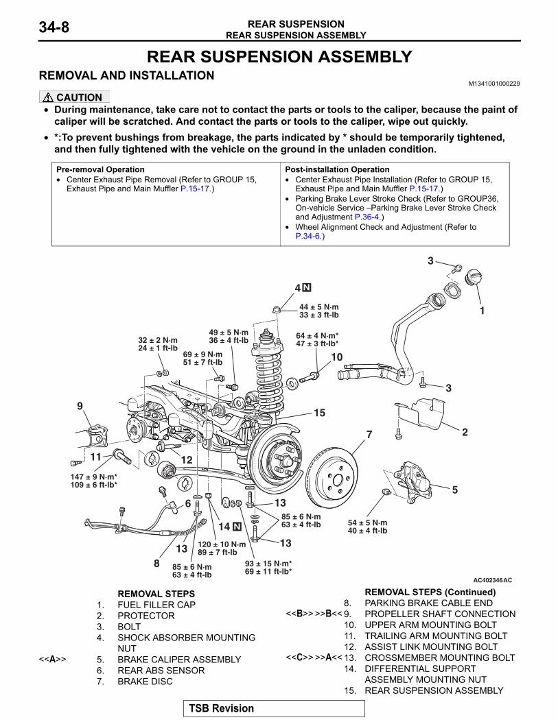
REAR SUSPENSION ASSEMBLYREMOVAL AND INSTALLATION
M1341001000229
CAUTION• During maintenance, take care not to contact the parts or tools to the caliper, because the paint of
caliper will be scratched. And contact the parts or tools to the caliper, wipe out quickly.•
Pre-removal Operation• Center Exhaust Pipe Removal (Refer to GROUP 15,
Exhaust Pipe and Main Muffler P.15-17.)
Post-installation Operation• Center Exhaust Pipe Installation (Refer to GROUP 15,
Exhaust Pipe and Main Muffler P.15-17.)• Parking Brake Lever Stroke Check (Refer to GROUP36,
On-vehicle Service − Parking Brake Lever Stroke Check and Adjustment P.36-4.)
• Wheel Alignment Check and Adjustment (Refer to P.34-6.)
AC402346AC
4 N
44 ± 5 N·m33 ± 3 ft-lb
32 ± 2 N·m24 ± 1 ft-lb
49 ± 5 N·m36 ± 4 ft-lb
69 ± 9 N·m51 ± 7 ft-lb
9
11
N
147 ± 9 N·m*109 ± 6 ft-lb*
12
6
13
85 ± 6 N·m63 ± 4 ft-lb
8
120 ± 10 N·m89 ± 7 ft-lb
14
93 ± 15 N·m*69 ± 11 ft-lb*
85 ± 6 N·m63 ± 4 ft-lb
13
13
54 ± 5 N·m40 ± 4 ft-lb
5
7
15
2
10
64 ± 4 N·m*47 ± 3 ft-lb*
3
3
1
REMOVAL STEPS 1. FUEL FILLER CAP2. PROTECTOR3. BOLT4. SHOCK ABSORBER MOUNTING
NUT<<A>> 5. BRAKE CALIPER ASSEMBLY
6. REAR ABS SENSOR7. BRAKE DISC
8. PARKING BRAKE CABLE END<<B>> >>B<< 9. PROPELLER SHAFT CONNECTION
10. UPPER ARM MOUNTING BOLT11. TRAILING ARM MOUNTING BOLT12. ASSIST LINK MOUNTING BOLT
<<C>> >>A<< 13. CROSSMEMBER MOUNTING BOLT14. DIFFERENTIAL SUPPORT
ASSEMBLY MOUNTING NUT15. REAR SUSPENSION ASSEMBLY
*:To prevent bushings from breakage, the parts indicated by * should be temporarily tightened, and then fully tightened with the vehicle on the ground in the unladen condition.
REMOVAL STEPS (Continued)
TSB Revision
REAR SUSPENSION ASSEMBLYREAR SUSPENSION 34-9
REMOVAL SERVICE POINTS.
<<A>> BRAKE CALIPER ASSEMBLY REMOVALCAUTION
Take care not to contact the parts or tools to the caliper because the paint of caliper will be scratched. And if there is brake fluid on the caliper, wipe it off quickly.Remove the brake caliper assembly and support with wire..
<<B>> PROPELLER SHAFT DISCONNECTION1. Mark the mating mark on the companion flange of the
differential carrier and the flange yoke of the propeller shaft.2. Remove the propeller shaft mounting bolt and nut..
<<C>> CROSSMEMBER MOUNTING BOLT REMOVALSupport the differential case with a garage jack or transmission jack, then remove the crossmember mounting bolt.
INSTALLATION SERVICE POINTS.
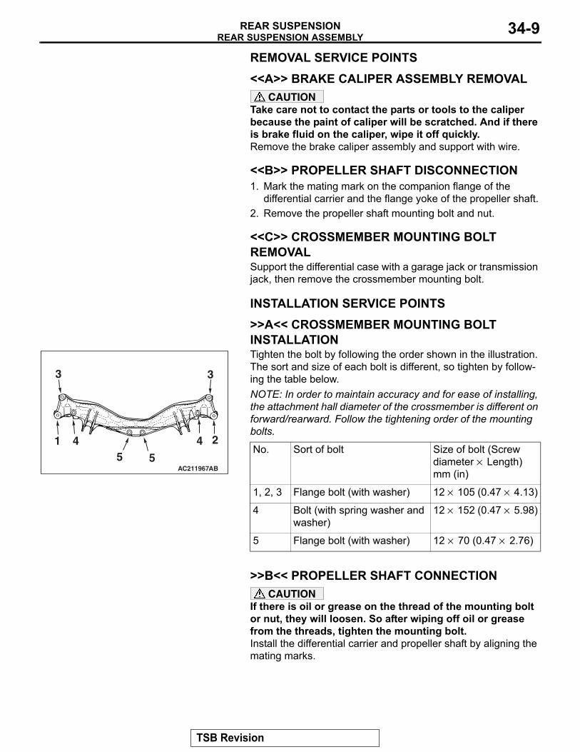
>>A<< CROSSMEMBER MOUNTING BOLT INSTALLATION
AC211967
1 45 5
4 2
33
AB
Tighten the bolt by following the order shown in the illustration. The sort and size of each bolt is different, so tighten by follow-ing the table below.NOTE: In order to maintain accuracy and for ease of installing, the attachment hall diameter of the crossmember is different on forward/rearward. Follow the tightening order of the mounting bolts.
No. Sort of bolt Size of bolt (Screw diameter × Length) mm (in)
1, 2, 3 Flange bolt (with washer) 12 × 105 (0.47 × 4.13)
4 Bolt (with spring washer and washer)
12 × 152 (0.47 × 5.98)
5 Flange bolt (with washer) 12 × 70 (0.47 × 2.76)
.
>>B<< PROPELLER SHAFT CONNECTIONCAUTION
If there is oil or grease on the thread of the mounting bolt or nut, they will loosen. So after wiping off oil or grease from the threads, tighten the mounting bolt.Install the differential carrier and propeller shaft by aligning the mating marks.
TSB Revision
UPPER ARM ASSEMBLYREAR SUSPENSION34-10
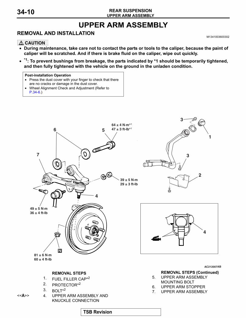
UPPER ARM ASSEMBLYREMOVAL AND INSTALLATION
M1341003600302
CAUTION• During maintenance, take care not to contact the parts or tools to the caliper, because the paint of
caliper will be scratched. And if there is brake fluid on the caliper, wipe out quickly.•
Post-installation Operation• Press the dust cover with your finger to check that there
are no cracks or damage in the dust cover.• Wheel Alignment Check and Adjustment (Refer to
P.34-6.)
AC212007
2
7
1
AB
39 ± 5 N·m29 ± 3 ft-lb
64 ± 4 N·m47 ± 3 ft-lb
4
3
3¹*¹*56
4
N81 ± 6 N·m60 ± 4 ft-lb
49 ± 5 N·m36 ± 4 ft-lb
REMOVAL STEPS 1. FUEL FILLER CAP*2
2. PROTECTOR*2
3. BOLT*2
<<A>> 4. UPPER ARM ASSEMBLY AND KNUCKLE CONNECTION
5. UPPER ARM ASSEMBLY MOUNTING BOLT
6. UPPER ARM STOPPER7. UPPER ARM ASSEMBLY
*1: To prevent bushings from breakage, the parts indicated by *1 should be temporarily tightened, and then fully tightened with the vehicle on the ground in the unladen condition.
REMOVAL STEPS (Continued)
TSB Revision
UPPER ARM ASSEMBLYREAR SUSPENSION 34-11
NOTE: Install/remove the parts with the mark "*2" when installing/removing the LH side upper arm assembly.
Required Special Tool:• MB991897: Ball Joint Remover
REMOVAL SERVICE POINTS.
<<A>> UPPER ARM BALL JOINT AND KNUCKLE DISCONNECTION
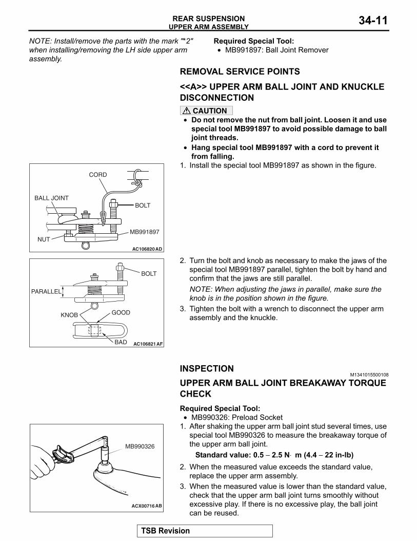
CAUTION• Do not remove the nut from ball joint. Loosen it and use
special tool MB991897 to avoid possible damage to ball joint threads.
•
AC106820AD
CORD
BOLT
MB991897NUT
BALL JOINT
Hang special tool MB991897 with a cord to prevent it from falling.
1. Install the special tool MB991897 as shown in the figure.
AC106821
KNOB
PARALLEL
BOLT
GOOD
BAD AF
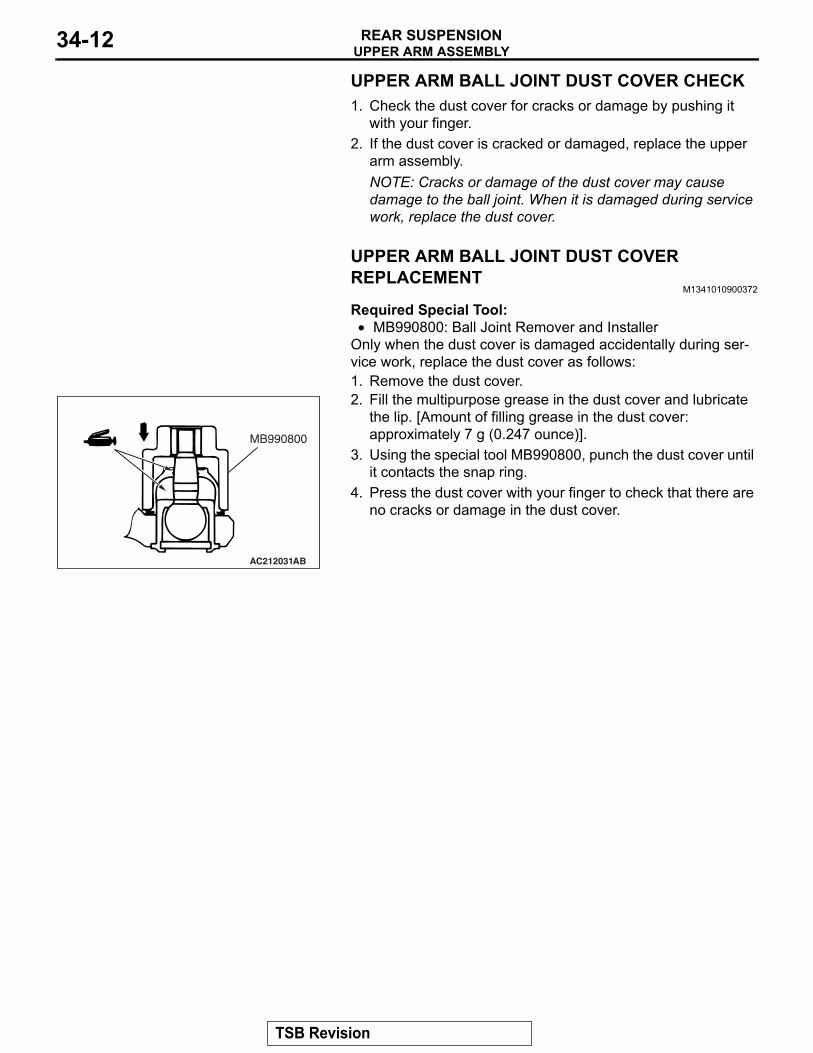
2. Turn the bolt and knob as necessary to make the jaws of the special tool MB991897 parallel, tighten the bolt by hand and confirm that the jaws are still parallel.NOTE: When adjusting the jaws in parallel, make sure the knob is in the position shown in the figure.
3. Tighten the bolt with a wrench to disconnect the upper arm assembly and the knuckle.
INSPECTIONM1341015500108
UPPER ARM BALL JOINT BREAKAWAY TORQUE CHECKRequired Special Tool:•
ACX00716
MB990326
AB
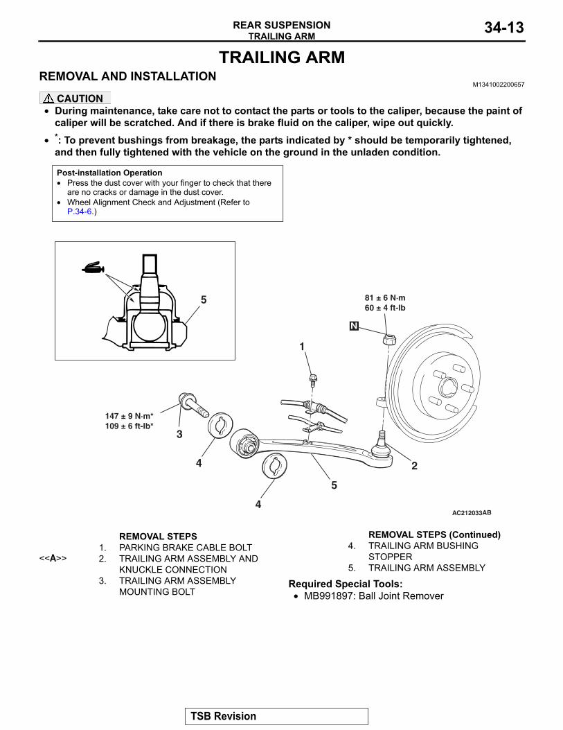
MB990326: Preload Socket1. After shaking the upper arm ball joint stud several times, use
special tool MB990326 to measure the breakaway torque of the upper arm ball joint.
Standard value: 0.5 − 2.5 N⋅ m (4.4 − 22 in-lb)2. When the measured value exceeds the standard value,
replace the upper arm assembly.3. When the measured value is lower than the standard value,
check that the upper arm ball joint turns smoothly without excessive play. If there is no excessive play, the ball joint can be reused.
TSB Revision
UPPER ARM ASSEMBLYREAR SUSPENSION34-12
UPPER ARM BALL JOINT DUST COVER CHECK1. Check the dust cover for cracks or damage by pushing it
with your finger.2. If the dust cover is cracked or damaged, replace the upper
arm assembly.NOTE: Cracks or damage of the dust cover may cause damage to the ball joint. When it is damaged during service work, replace the dust cover.
UPPER ARM BALL JOINT DUST COVER REPLACEMENT
M1341010900372
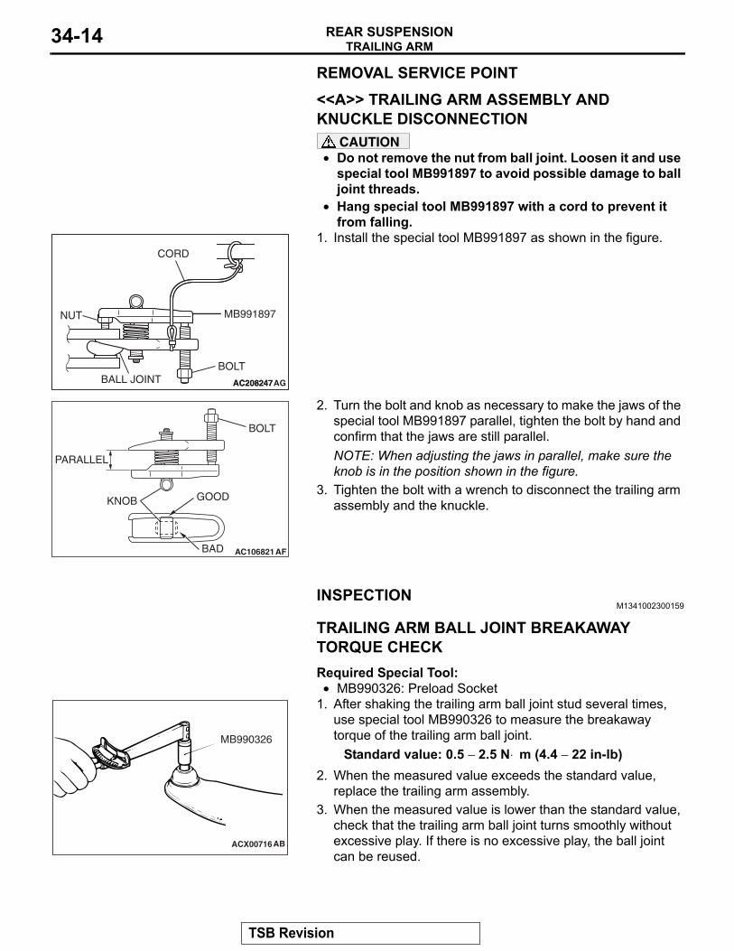
Required Special Tool:• MB990800: Ball Joint Remover and Installer
Only when the dust cover is damaged accidentally during ser-vice work, replace the dust cover as follows:1. Remove the dust cover.
AC212031AB
MB990800
2. Fill the multipurpose grease in the dust cover and lubricate the lip. [Amount of filling grease in the dust cover: approximately 7 g (0.247 ounce)].
3. Using the special tool MB990800, punch the dust cover until it contacts the snap ring.
4. Press the dust cover with your finger to check that there are no cracks or damage in the dust cover.
TSB Revision
TRAILING ARMREAR SUSPENSION 34-13
TRAILING ARMREMOVAL AND INSTALLATION
M1341002200657
CAUTION• During maintenance, take care not to contact the parts or tools to the caliper, because the paint of
caliper will be scratched. And if there is brake fluid on the caliper, wipe out quickly.•
Post-installation Operation• Press the dust cover with your finger to check that there
are no cracks or damage in the dust cover.• Wheel Alignment Check and Adjustment (Refer to
P.34-6.)
AC212033
5
4
5
AB
81 ± 6 N·m60 ± 4 ft-lb
N
147 ± 9 N·m*109 ± 6 ft-lb*
3
4
1
2
REMOVAL STEPS 1. PARKING BRAKE CABLE BOLT
<<A>> 2. TRAILING ARM ASSEMBLY AND KNUCKLE CONNECTION
3. TRAILING ARM ASSEMBLY MOUNTING BOLT
4. TRAILING ARM BUSHING STOPPER
5. TRAILING ARM ASSEMBLY
*: To prevent bushings from breakage, the parts indicated by * should be temporarily tightened, and then fully tightened with the vehicle on the ground in the unladen condition.
Required Special Tools:• MB991897: Ball Joint Remover
REMOVAL STEPS (Continued)
TSB Revision
TRAILING ARMREAR SUSPENSION34-14
REMOVAL SERVICE POINT.
<<A>> TRAILING ARM ASSEMBLY AND KNUCKLE DISCONNECTION
CAUTION• Do not remove the nut from ball joint. Loosen it and use
special tool MB991897 to avoid possible damage to ball joint threads.
•
AC208247AC208247AG
CORD
BOLT
MB991897NUT
BALL JOINT
Hang special tool MB991897 with a cord to prevent it from falling.
1. Install the special tool MB991897 as shown in the figure.
AC106821
KNOB
PARALLEL
BOLT
GOOD
BAD AF
2. Turn the bolt and knob as necessary to make the jaws of the special tool MB991897 parallel, tighten the bolt by hand and confirm that the jaws are still parallel.NOTE: When adjusting the jaws in parallel, make sure the knob is in the position shown in the figure.
3. Tighten the bolt with a wrench to disconnect the trailing arm assembly and the knuckle.
INSPECTIONM1341002300159
.
TRAILING ARM BALL JOINT BREAKAWAY TORQUE CHECKRequired Special Tool:•
ACX00716
MB990326
AB
MB990326: Preload Socket1. After shaking the trailing arm ball joint stud several times,
use special tool MB990326 to measure the breakaway torque of the trailing arm ball joint.
Standard value: 0.5 − 2.5 N⋅ m (4.4 − 22 in-lb)2. When the measured value exceeds the standard value,
replace the trailing arm assembly.3. When the measured value is lower than the standard value,
check that the trailing arm ball joint turns smoothly without excessive play. If there is no excessive play, the ball joint can be reused.
.
TSB Revision
TRAILING ARMREAR SUSPENSION 34-15
TRAILING ARM BALL JOINT DUST COVER CHECK1. Check the dust cover for cracks or damage by pushing it
with your finger.2. If the dust cover is cracked or damaged, replace the trailing
arm assembly.NOTE: Cracks or damage to the dust cover may cause damage to the ball joint. When it is damaged during service work, replace the dust cover.
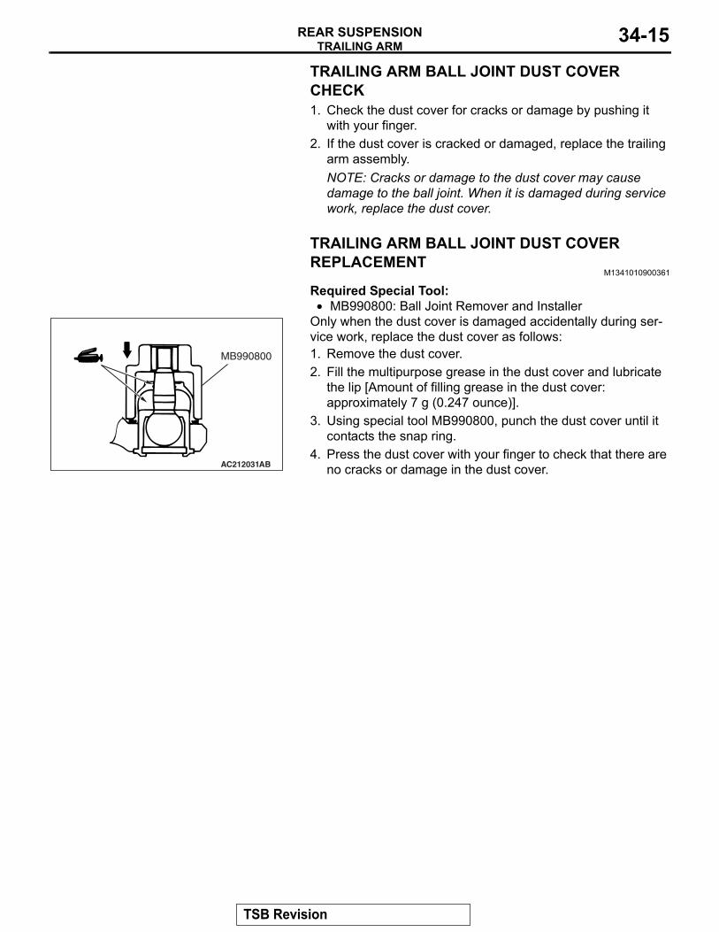
TRAILING ARM BALL JOINT DUST COVER REPLACEMENT
M1341010900361
Required Special Tool:•
AC212031AB
MB990800
MB990800: Ball Joint Remover and InstallerOnly when the dust cover is damaged accidentally during ser-vice work, replace the dust cover as follows:1. Remove the dust cover.2. Fill the multipurpose grease in the dust cover and lubricate
the lip [Amount of filling grease in the dust cover: approximately 7 g (0.247 ounce)].
3. Using special tool MB990800, punch the dust cover until it contacts the snap ring.
4. Press the dust cover with your finger to check that there are no cracks or damage in the dust cover.
TSB Revision
LOWER ARM ASSEMBLY AND ASSIST LINKREAR SUSPENSION34-16
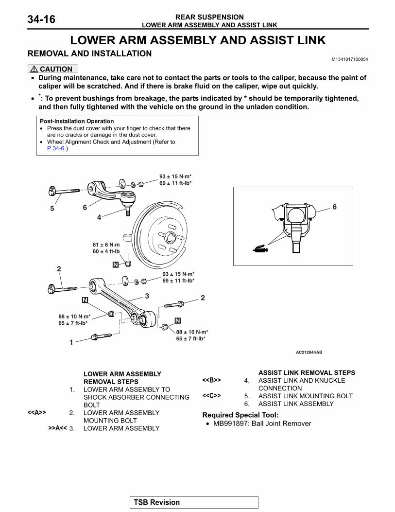
LOWER ARM ASSEMBLY AND ASSIST LINKREMOVAL AND INSTALLATION
M1341017100054
CAUTION• During maintenance, take care not to contact the parts or tools to the caliper, because the paint of
caliper will be scratched. And if there is brake fluid on the caliper, wipe out quickly.•
Post-installation Operation• Press the dust cover with your finger to check that there
are no cracks or damage in the dust cover.• Wheel Alignment Check and Adjustment (Refer to
P.34-6.)
AC212044
1AB
88 ± 10 N·m*65 ± 7 ft-lb*
4
N
88 ± 10 N·m*65 ± 7 ft-lb*
3 2
N
93 ± 15 N·m*69 ± 11 ft-lb*
2
81 ± 6 N·m60 ± 4 ft-lb
N
65
93 ± 15 N·m*69 ± 11 ft-lb*
6
LOWER ARM ASSEMBLY REMOVAL STEPS
1. LOWER ARM ASSEMBLY TO SHOCK ABSORBER CONNECTING BOLT
<<A>> 2. LOWER ARM ASSEMBLY MOUNTING BOLT
>>A<< 3. LOWER ARM ASSEMBLY
ASSIST LINK REMOVAL STEPS <<B>> 4. ASSIST LINK AND KNUCKLE
CONNECTION<<C>> 5. ASSIST LINK MOUNTING BOLT
6. ASSIST LINK ASSEMBLY
*: To prevent bushings from breakage, the parts indicated by * should be temporarily tightened, and then fully tightened with the vehicle on the ground in the unladen condition.
Required Special Tool:• MB991897: Ball Joint Remover
TSB Revision
LOWER ARM ASSEMBLY AND ASSIST LINKREAR SUSPENSION 34-17
REMOVAL SERVICE POINTS.
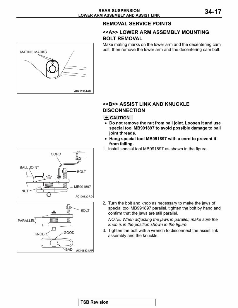
<<A>> LOWER ARM ASSEMBLY MOUNTING BOLT REMOVAL
AC211954
MATING MARKS
AC
Make mating marks on the lower arm and the decentering cam bolt, then remove the lower arm and the decentering cam bolt.
.
<<B>> ASSIST LINK AND KNUCKLE DISCONNECTION
CAUTION• Do not remove the nut from ball joint. Loosen it and use
special tool MB991897 to avoid possible damage to ball joint threads.
•
AC106820AD
CORD
BOLT
MB991897NUT
BALL JOINT
Hang special tool MB991897 with a cord to prevent it from falling.
1. Install special tool MB991897 as shown in the figure.
AC106821
KNOB
PARALLEL
BOLT
GOOD
BAD AF
2. Turn the bolt and knob as necessary to make the jaws of special tool MB991897 parallel, tighten the bolt by hand and confirm that the jaws are still parallel.NOTE: When adjusting the jaws in parallel, make sure the knob is in the position shown in the figure.
3. Tighten the bolt with a wrench to disconnect the assist link assembly and the knuckle.
.
TSB Revision
LOWER ARM ASSEMBLY AND ASSIST LINKREAR SUSPENSION34-18
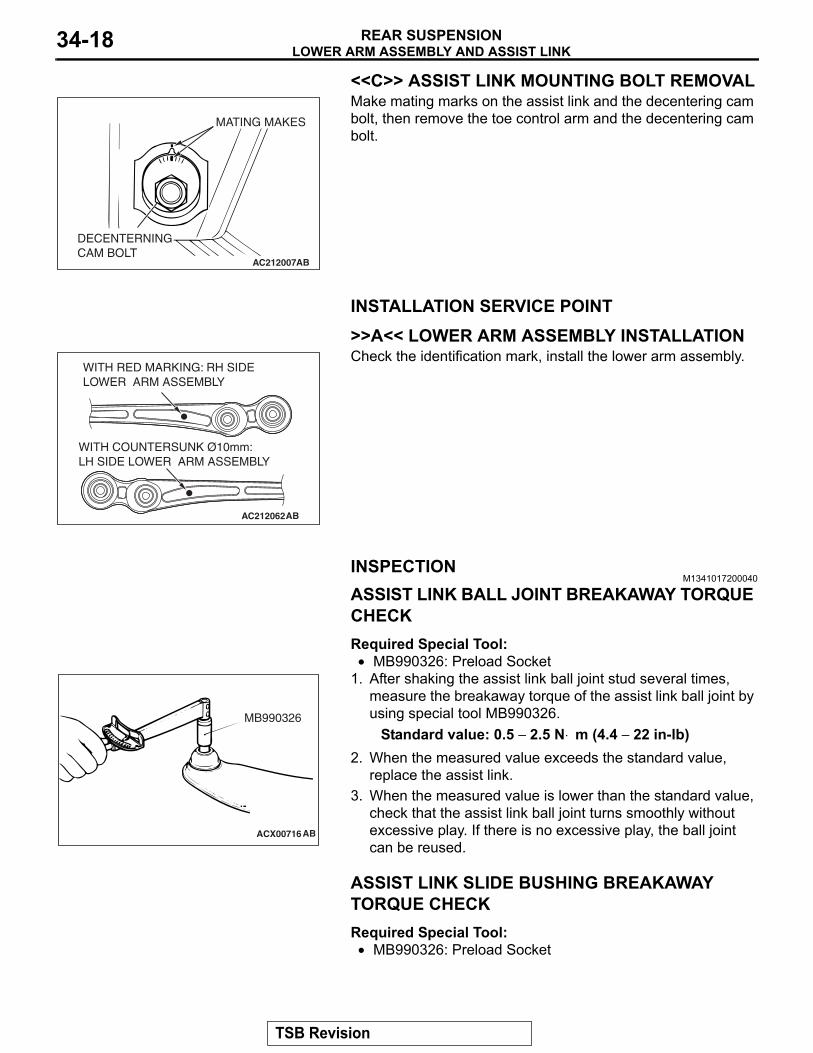
<<C>> ASSIST LINK MOUNTING BOLT REMOVAL
AC212007
MATING MAKES
DECENTERNINGCAM BOLT
AB
Make mating marks on the assist link and the decentering cam bolt, then remove the toe control arm and the decentering cam bolt.
INSTALLATION SERVICE POINT.
>>A<< LOWER ARM ASSEMBLY INSTALLATION
AC212062AB
WITH COUNTERSUNK Ø10mm: LH SIDE LOWER ARM ASSEMBLY
WITH RED MARKING: RH SIDE LOWER ARM ASSEMBLY
Check the identification mark, install the lower arm assembly.
INSPECTIONM1341017200040
ASSIST LINK BALL JOINT BREAKAWAY TORQUE CHECKRequired Special Tool:•
ACX00716
MB990326
AB
MB990326: Preload Socket1. After shaking the assist link ball joint stud several times,
measure the breakaway torque of the assist link ball joint by using special tool MB990326.
Standard value: 0.5 − 2.5 N⋅ m (4.4 − 22 in-lb)2. When the measured value exceeds the standard value,
replace the assist link.3. When the measured value is lower than the standard value,
check that the assist link ball joint turns smoothly without excessive play. If there is no excessive play, the ball joint can be reused.
ASSIST LINK SLIDE BUSHING BREAKAWAY TORQUE CHECKRequired Special Tool:• MB990326: Preload Socket
TSB Revision
LOWER ARM ASSEMBLY AND ASSIST LINKREAR SUSPENSION 34-19
AC212117
MB990326
AB
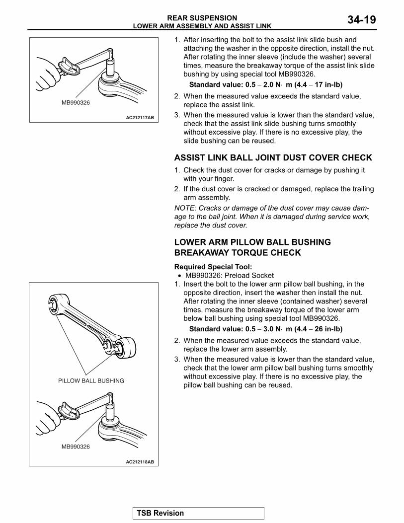
1. After inserting the bolt to the assist link slide bush and attaching the washer in the opposite direction, install the nut. After rotating the inner sleeve (include the washer) several times, measure the breakaway torque of the assist link slide bushing by using special tool MB990326.
Standard value: 0.5 − 2.0 N⋅ m (4.4 − 17 in-lb)2. When the measured value exceeds the standard value,
replace the assist link.3. When the measured value is lower than the standard value,
check that the assist link slide bushing turns smoothly without excessive play. If there is no excessive play, the slide bushing can be reused.
ASSIST LINK BALL JOINT DUST COVER CHECK1. Check the dust cover for cracks or damage by pushing it
with your finger.2. If the dust cover is cracked or damaged, replace the trailing
arm assembly.NOTE: Cracks or damage of the dust cover may cause dam-age to the ball joint. When it is damaged during service work, replace the dust cover.
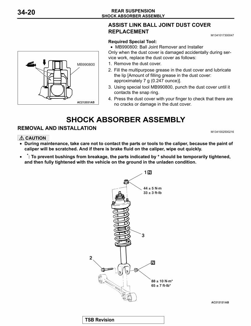
LOWER ARM PILLOW BALL BUSHING BREAKAWAY TORQUE CHECKRequired Special Tool:•
AC212118
MB990326
AB
PILLOW BALL BUSHING
MB990326: Preload Socket1. Insert the bolt to the lower arm pillow ball bushing, in the
opposite direction, insert the washer then install the nut. After rotating the inner sleeve (contained washer) several times, measure the breakaway torque of the lower arm below ball bushing using special tool MB990326.
Standard value: 0.5 − 3.0 N⋅ m (4.4 − 26 in-lb)2. When the measured value exceeds the standard value,
replace the lower arm assembly.3. When the measured value is lower than the standard value,
check that the lower arm pillow ball bushing turns smoothly without excessive play. If there is no excessive play, the pillow ball bushing can be reused.
TSB Revision
SHOCK ABSORBER ASSEMBLYREAR SUSPENSION34-20
ASSIST LINK BALL JOINT DUST COVER REPLACEMENT
M1341017300047
Required Special Tool:•
AC212031AB
MB990800
MB990800: Ball Joint Remover and InstallerOnly when the dust cover is damaged accidentally during ser-vice work, replace the dust cover as follows:1. Remove the dust cover.2. Fill the multipurpose grease in the dust cover and lubricate
the lip [Amount of filling grease in the dust cover: approximately 7 g (0.247 ounce)].
3. Using special tool MB990800, punch the dust cover until it contacts the snap ring.
4. Press the dust cover with your finger to check that there are no cracks or damage in the dust cover.
SHOCK ABSORBER ASSEMBLYREMOVAL AND INSTALLATION
M1341002500216
CAUTION• During maintenance, take care not to contact the parts or tools to the caliper, because the paint of
caliper will be scratched. And if there is brake fluid on the caliper, wipe out quickly.•
AC212121
3
88 ± 10 N·m*65 ± 7 ft-lb*
1
N
44 ± 5 N·m33 ± 3 ft-lb
N
2
AB
*: To prevent bushings from breakage, the parts indicated by * should be temporarily tightened, and then fully tightened with the vehicle on the ground in the unladen condition.
TSB Revision
SHOCK ABSORBER ASSEMBLYREAR SUSPENSION 34-21
REMOVAL STEPS 1. COIL SPRING NUT 2. COIL SPRING BOLT
3. SHOCK ABSORBER ASSEMBLY
DISASSEMBLY AND ASSEMBLYM1341005300192
AC212125
10
1
25 ± 5 N·m19 ± 3 ft-lb
N
12AB
11
9
8
6
57
4
32
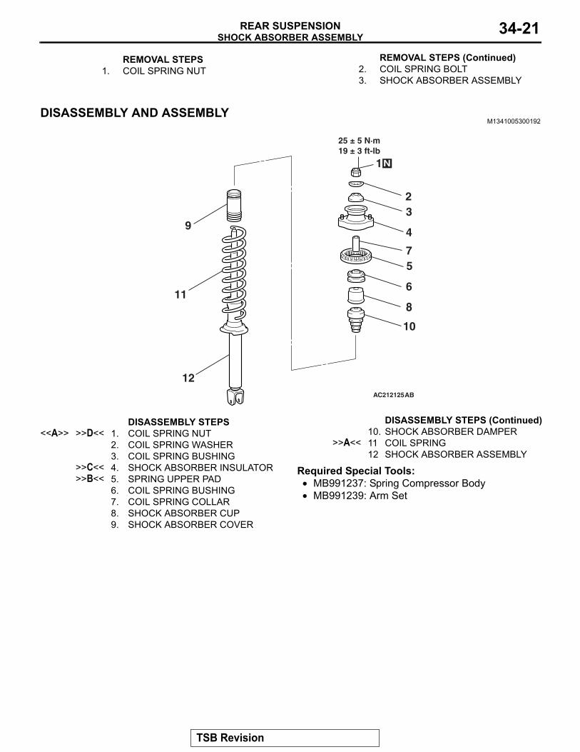
DISASSEMBLY STEPS <<A>> >>D<< 1. COIL SPRING NUT
2. COIL SPRING WASHER3. COIL SPRING BUSHING
>>C<< 4. SHOCK ABSORBER INSULATOR>>B<< 5. SPRING UPPER PAD
6. COIL SPRING BUSHING7. COIL SPRING COLLAR8. SHOCK ABSORBER CUP9. SHOCK ABSORBER COVER
10. SHOCK ABSORBER DAMPER>>A<< 11 COIL SPRING
12 SHOCK ABSORBER ASSEMBLY
Required Special Tools:• MB991237: Spring Compressor Body• MB991239: Arm Set
REMOVAL STEPS (Continued)
DISASSEMBLY STEPS (Continued)
TSB Revision
SHOCK ABSORBER ASSEMBLYREAR SUSPENSION34-22
DISASSEMBLY SERVICE POINT.
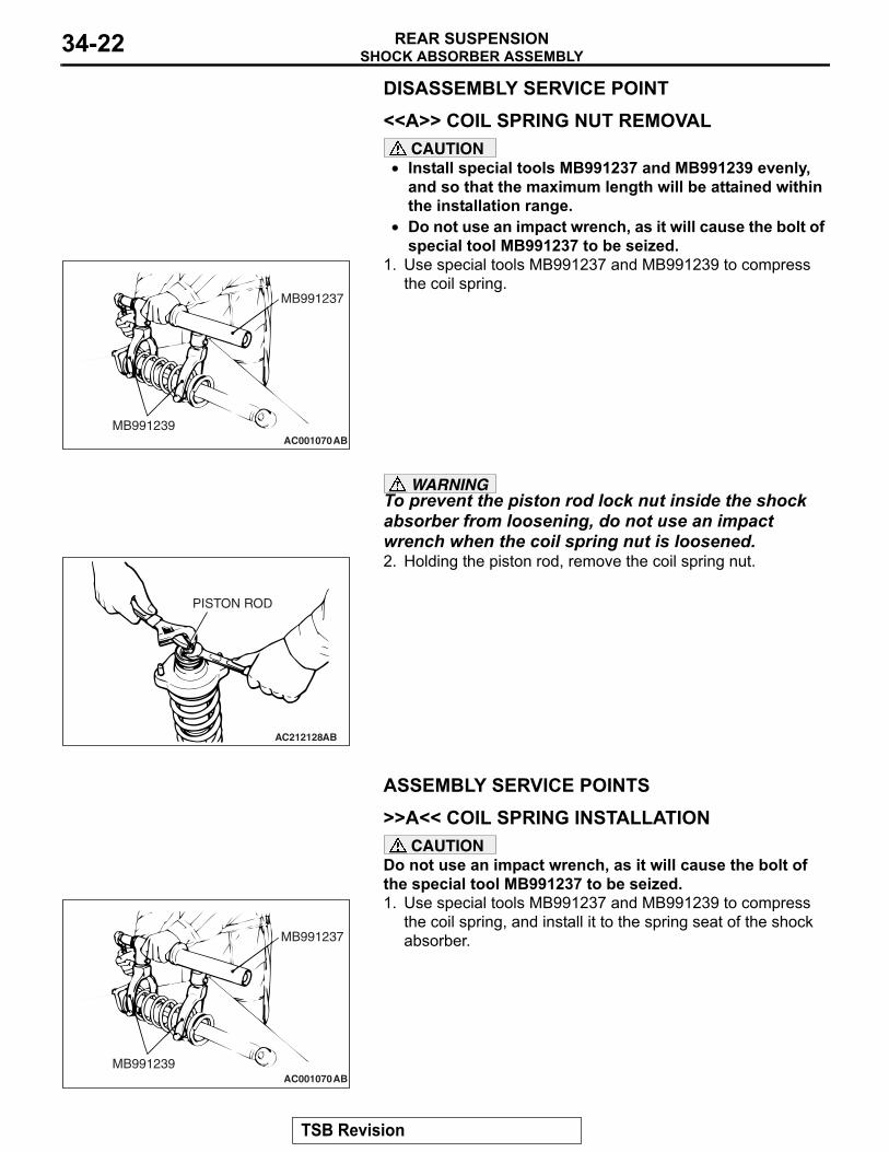
<<A>> COIL SPRING NUT REMOVALCAUTION
• Install special tools MB991237 and MB991239 evenly, and so that the maximum length will be attained within the installation range.
•
AC001070
MB991237
MB991239AB
Do not use an impact wrench, as it will cause the bolt of special tool MB991237 to be seized.
1. Use special tools MB991237 and MB991239 to compress the coil spring.
WARNINGTo prevent the piston rod lock nut inside the shock absorber from loosening, do not use an impact wrench when the coil spring nut is loosened.
AC212128
PISTON ROD
AB
2. Holding the piston rod, remove the coil spring nut.
ASSEMBLY SERVICE POINTS.
>>A<< COIL SPRING INSTALLATIONCAUTION
Do not use an impact wrench, as it will cause the bolt of the special tool MB991237 to be seized.
AC001070
MB991237
MB991239AB
1. Use special tools MB991237 and MB991239 to compress the coil spring, and install it to the spring seat of the shock absorber.
TSB Revision
SHOCK ABSORBER ASSEMBLYREAR SUSPENSION 34-23
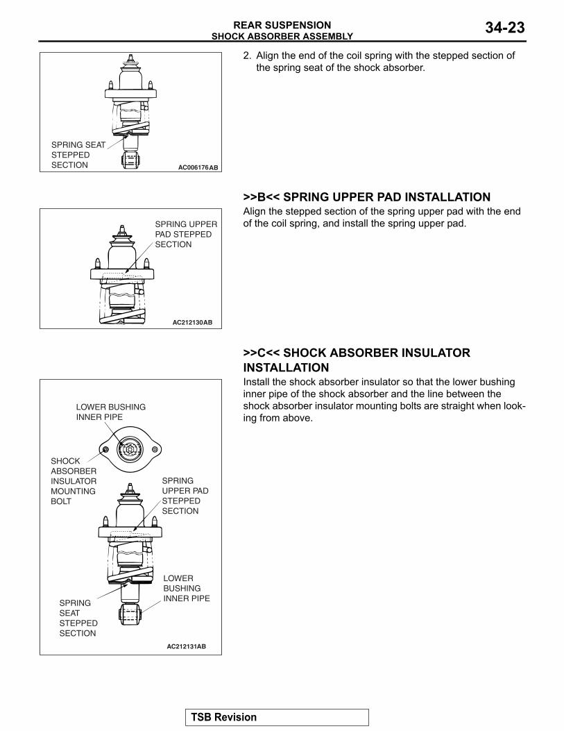
AC006176AB
SPRING SEATSTEPPEDSECTION
2. Align the end of the coil spring with the stepped section of the spring seat of the shock absorber.
.
>>B<< SPRING UPPER PAD INSTALLATION
AC212130
SPRING UPPERPAD STEPPEDSECTION
AB
Align the stepped section of the spring upper pad with the end of the coil spring, and install the spring upper pad.
.
>>C<< SHOCK ABSORBER INSULATOR INSTALLATION
AC212131
LOWER BUSHINGINNER PIPE
SHOCK ABSORBER INSULATOR MOUNTING BOLT
SPRING UPPER PAD STEPPED SECTION
SPRING SEATSTEPPED SECTION
LOWER BUSHINGINNER PIPE
AB
Install the shock absorber insulator so that the lower bushing inner pipe of the shock absorber and the line between the shock absorber insulator mounting bolts are straight when look-ing from above.
.
TSB Revision
SHOCK ABSORBER ASSEMBLYREAR SUSPENSION34-24
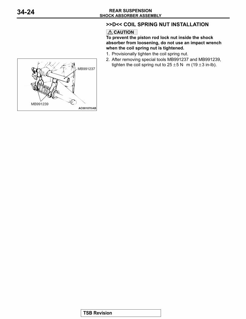
>>D<< COIL SPRING NUT INSTALLATIONCAUTION
To prevent the piston rod lock nut inside the shock absorber from loosening, do not use an impact wrench when the coil spring nut is tightened.1. Provisionally tighten the coil spring nut.
AC001070
MB991237
MB991239AB
2. After removing special tools MB991237 and MB991239, tighten the coil spring nut to 25 ± 5 N⋅ m (19 ± 3 in-lb).
TSB Revision
STABILIZER BARREAR SUSPENSION 34-25
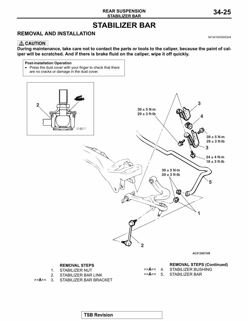
STABILIZER BARREMOVAL AND INSTALLATION
M1341003000344
CAUTIONDuring maintenance, take care not to contact the parts or tools to the caliper, because the paint of cal-iper will be scratched. And if there is brake fluid on the caliper, wipe it off quickly.
Post-installation Operation• Press the dust cover with your finger to check that there
are no cracks or damage in the dust cover.
AC212007
39 ± 5 N·m29 ± 3 ft-lb
AB
32
4
39 ± 5 N·m29 ± 3 ft-lb
3
24 ± 4 N·m18 ± 3 ft-lb
5
39 ± 5 N·m29 ± 3 ft-lb
1
2
REMOVAL STEPS 1. STABILIZER NUT2. STABILIZER BAR LINK
>>A<< 3. STABILIZER BAR BRACKET
>>A<< 4. STABILIZER BUSHING>>A<< 5. STABILIZER BAR
REMOVAL STEPS (Continued)
TSB Revision
STABILIZER BARREAR SUSPENSION34-26
INSTALLATION SERVICE POINT.
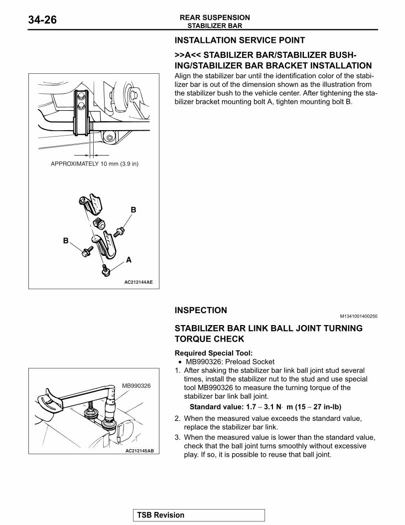
>>A<< STABILIZER BAR/STABILIZER BUSH-ING/STABILIZER BAR BRACKET INSTALLATION
AC212144
APPROXIMATELY 10 mm (3.9 in)
A
B
B
AE
Align the stabilizer bar until the identification color of the stabi-lizer bar is out of the dimension shown as the illustration from the stabilizer bush to the vehicle center. After tightening the sta-bilizer bracket mounting bolt A, tighten mounting bolt B.
INSPECTIONM1341001400250
.
STABILIZER BAR LINK BALL JOINT TURNING TORQUE CHECKRequired Special Tool:•
AC212145
MB990326
AB
MB990326: Preload Socket1. After shaking the stabilizer bar link ball joint stud several
times, install the stabilizer nut to the stud and use special tool MB990326 to measure the turning torque of the stabilizer bar link ball joint.
Standard value: 1.7 − 3.1 N⋅ m (15 − 27 in-lb)2. When the measured value exceeds the standard value,
replace the stabilizer bar link.3. When the measured value is lower than the standard value,
check that the ball joint turns smoothly without excessive play. If so, it is possible to reuse that ball joint.
.
TSB Revision
STABILIZER BARREAR SUSPENSION 34-27
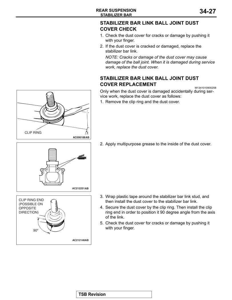
STABILIZER BAR LINK BALL JOINT DUST COVER CHECK1. Check the dust cover for cracks or damage by pushing it
with your finger.2. If the dust cover is cracked or damaged, replace the
stabilizer bar link.NOTE: Cracks or damage of the dust cover may cause damage of the ball joint. When it is damaged during service work, replace the dust cover.
STABILIZER BAR LINK BALL JOINT DUST COVER REPLACEMENT
M1341010900208
AC006188AB
CLIP RING
Only when the dust cover is damaged accidentally during ser-vice work, replace the dust cover as follows:1. Remove the clip ring and the dust cover.
AC212251AB
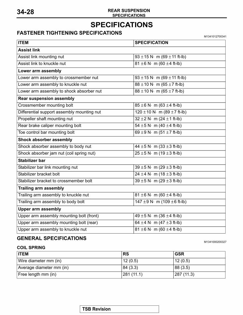
2. Apply multipurpose grease to the inside of the dust cover.
AC212146
90º
CLIP RING END(POSSIBLE ON OPPOSITE DIRECTION)
AB
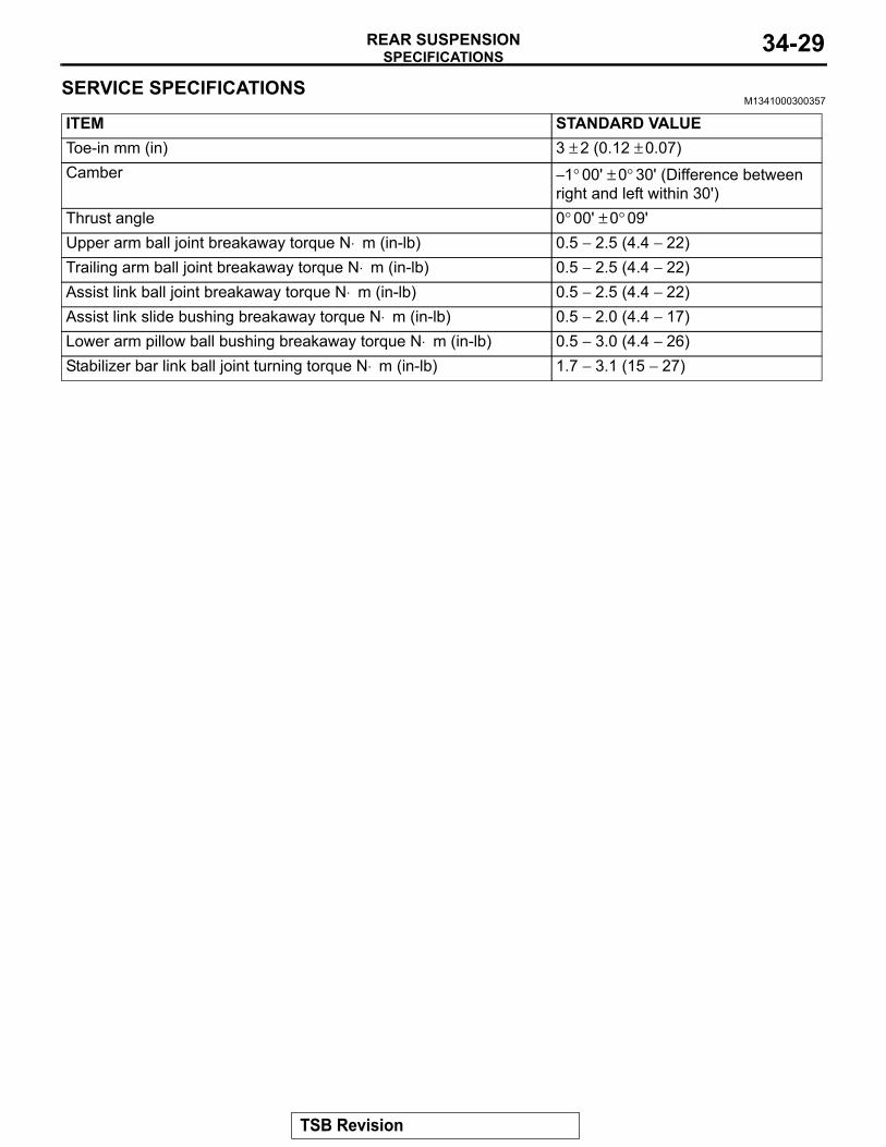
3. Wrap plastic tape around the stabilizer bar link stud, and then install the dust cover to the stabilizer bar link.
4. Secure the dust cover by the clip ring. Then install the clip ring end in order to position it 90 degree angle from the axis of the link.
5. Check the dust cover for cracks or damage by pushing it with your finger.
TSB Revision
SPECIFICATIONSREAR SUSPENSION34-28
SPECIFICATIONSFASTENER TIGHTENING SPECIFICATIONS
M1341012700341
ITEM SPECIFICATIONAssist linkAssist link mounting nut 93 ± 15 N⋅ m (69 ± 11 ft-lb)Assist link to knuckle nut 81 ± 6 N⋅ m (60 ± 4 ft-lb)
Lower arm assemblyLower arm assembly to crossmember nut 93 ± 15 N⋅ m (69 ± 11 ft-lb)Lower arm assembly to knuckle nut 88 ± 10 N⋅ m (65 ± 7 ft-lb)Lower arm assembly to shock absorber nut 88 ± 10 N⋅ m (65 ± 7 ft-lb)
Rear suspension assemblyCrossmember mounting bolt 85 ± 6 N⋅ m (63 ± 4 ft-lb)Differential support assembly mounting nut 120 ± 10 N⋅ m (89 ± 7 ft-lb)Propeller shaft mounting nut 32 ± 2 N⋅ m (24 ± 1 ft-lb)Rear brake caliper mounting bolt 54 ± 5 N⋅ m (40 ± 4 ft-lb)Toe control bar mounting bolt 69 ± 9 N⋅ m (51 ± 7 ft-lb)
Shock absorber assemblyShock absorber assembly to body nut 44 ± 5 N⋅ m (33 ± 3 ft-lb)Shock absorber jam nut (coil spring nut) 25 ± 5 N⋅ m (19 ± 3 ft-lb)
Stabilizer barStabilizer bar link mounting nut 39 ± 5 N⋅ m (29 ± 3 ft-lb)Stabilizer bracket bolt 24 ± 4 N⋅ m (18 ± 3 ft-lb)Stabilizer bracket to crossmember bolt 39 ± 5 N⋅ m (29 ± 3 ft-lb)
Trailing arm assemblyTrailing arm assembly to knuckle nut 81 ± 6 N⋅ m (60 ± 4 ft-lb)Trailing arm assembly to body bolt 147 ± 9 N⋅ m (109 ± 6 ft-lb)
Upper arm assemblyUpper arm assembly mounting bolt (front) 49 ± 5 N⋅ m (36 ± 4 ft-lb)Upper arm assembly mounting bolt (rear) 64 ± 4 N⋅ m (47 ± 3 ft-lb)Upper arm assembly to knuckle nut 81 ± 6 N⋅ m (60 ± 4 ft-lb)
GENERAL SPECIFICATIONSM1341000200327
COIL SPRINGITEM RS GSRWire diameter mm (in) 12 (0.5) 12 (0.5)Average diameter mm (in) 84 (3.3) 88 (3.5)Free length mm (in) 281 (11.1) 287 (11.3)
TSB Revision
SPECIFICATIONSREAR SUSPENSION 34-29
SERVICE SPECIFICATIONSM1341000300357
ITEM STANDARD VALUEToe-in mm (in) 3 ± 2 (0.12 ± 0.07)Camber − 1° 00' ± 0° 30' (Difference between
right and left within 30')Thrust angle 0° 00' ± 0° 09'Upper arm ball joint breakaway torque N⋅ m (in-lb) 0.5 − 2.5 (4.4 − 22)Trailing arm ball joint breakaway torque N⋅ m (in-lb) 0.5 − 2.5 (4.4 − 22)Assist link ball joint breakaway torque N⋅ m (in-lb) 0.5 − 2.5 (4.4 − 22)Assist link slide bushing breakaway torque N⋅ m (in-lb) 0.5 − 2.0 (4.4 − 17)Lower arm pillow ball bushing breakaway torque N⋅ m (in-lb) 0.5 − 3.0 (4.4 − 26)Stabilizer bar link ball joint turning torque N⋅ m (in-lb) 1.7 − 3.1 (15 − 27)
TSB Revision
NOTES