Embed Size (px)
Citation preview
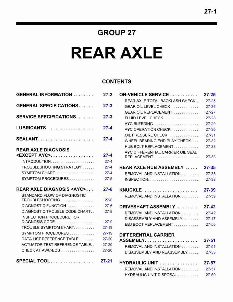
27-1
GROUP 27
REAR AXLECONTENTS
GENERAL INFORMATION . . . . . . . . 27-2
GENERAL SPECIFICATIONS. . . . . . 27-3
SERVICE SPECIFICATIONS. . . . . . . 27-3
LUBRICANTS . . . . . . . . . . . . . . . . . . 27-4
SEALANT. . . . . . . . . . . . . . . . . . . . . . 27-4
REAR AXLE DIAGNOSIS <EXCEPT AYC>. . . . . . . . . . . . . . . . . 27-4
INTRODUCTION. . . . . . . . . . . . . . . . . . . . . 27-4TROUBLESHOOTING STRATEGY . . . . . . 27-4SYMPTOM CHART. . . . . . . . . . . . . . . . . . . 27-4SYMPTOM PROCEDURES . . . . . . . . . . . . 27-5
REAR AXLE DIAGNOSIS <AYC>. . . 27-6STANDARD FLOW OF DIAGNOSTIC TROUBLESHOOTING . . . . . . . . . . . . . . . . 27-6DIAGNOSTIC FUNCTION . . . . . . . . . . . . . 27-6DIAGNOSTIC TROUBLE CODE CHART. . 27-8INSPECTION PROCEDURE FOR DIAGNOSIS CODE. . . . . . . . . . . . . . . . . . . 27-9TROUBLE SYMPTOM CHART. . . . . . . . . . 27-19SYMPTOM PROCEDURES . . . . . . . . . . . . 27-19DATA LIST REFERENCE TABLE . . . . . . . 27-20ACTUATOR TEST REFERENCE TABLE. . 27-20CHECK AT AWC-ECU . . . . . . . . . . . . . . . . 27-20
SPECIAL TOOL . . . . . . . . . . . . . . . . . 27-21
ON-VEHICLE SERVICE . . . . . . . . . . . 27-25REAR AXLE TOTAL BACKLASH CHECK . 27-25GEAR OIL LEVEL CHECK . . . . . . . . . . . . . 27-26GEAR OIL REPLACEMENT . . . . . . . . . . . . 27-27FLUID LEVEL CHECK . . . . . . . . . . . . . . . . 27-28AYC BLEEDING . . . . . . . . . . . . . . . . . . . . . 27-29AYC OPERATION CHECK . . . . . . . . . . . . . 27-30OIL PRESSURE CHECK . . . . . . . . . . . . . . 27-31WHEEL BEARING END PLAY CHECK . . . 27-32HUB BOLT REPLACEMENT. . . . . . . . . . . . 27-33AYC DIFFERENTIAL CARRIER OIL SEAL REPLACEMENT . . . . . . . . . . . . . . . . . . . . . 27-33
REAR AXLE HUB ASSEMBLY . . . . . 27-35REMOVAL AND INSTALLATION . . . . . . . . 27-35INSPECTION. . . . . . . . . . . . . . . . . . . . . . . . 27-38
KNUCKLE. . . . . . . . . . . . . . . . . . . . . . 27-39REMOVAL AND INSTALLATION . . . . . . . . 27-39
DRIVESHAFT ASSEMBLY. . . . . . . . . 27-42REMOVAL AND INSTALLATION . . . . . . . . 27-42DISASSEMBLY AND ASSEMBLY . . . . . . . 27-47EBJ BOOT REPLACEMENT. . . . . . . . . . . . 27-50
DIFFERENTIAL CARRIER ASSEMBLY. . . . . . . . . . . . . . . . . . . . . 27-51
REMOVAL AND INSTALLATION . . . . . . . . 27-51DISASSEMBLY AND REASSEMBLY . . . . . 27-53
HYDRAULIC UNIT . . . . . . . . . . . . . . . 27-57REMOVAL AND INSTALLATION . . . . . . . . 27-57HYDRAULIC UNIT DISPOSAL . . . . . . . . . . 27-59
GENERAL INFORMATIONREAR AXLE27-2
GENERAL INFORMATIONM1271000100887
For the rear axle, the unit bearing (double row angu-lar contact ball bearing) in which the hub and ball bearing are incorporated has been adopted for the rear wheel bearing, and the EBJ-ETJ type constant velocity joint for the rear driveshaft.There are the following features.• The lightweight rear driveshaft and compact
EBJ-ETJ type constant velocity joint have been equipped.
• The rear driveshaft spline diameter on the wheel-side and differential-side (LH) has been increased, improving torsional strength.
• The ABS magnetic encoder for wheel speed detection has been integrated into the rear wheel bearing, and the protector cover of magnetic encoder for wheel speed detection has been equipped to the driveshaft.
• The lead-free grease has been adopted for the constant velocity joint.
• Hexavalent chromium has been eliminated from the dust cover material and protector cover of magnetic encoder for wheel speed detection.
• The AYC differential has been equipped.NOTE: .EBJ (High Efficiency Compact Birfield Joint): the
lighter and smaller constant velocity joint com-pared with the conventional BJ has been achieved by adopting the eight small balls.
ETJ (High Efficiency Compact Tripod Joint): The lighter and smaller constant velocity joint com-pared with the conventional TJ has been installed.
.
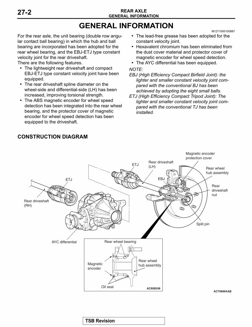
CONSTRUCTION DIAGRAM
AC706664
ETJ
EBJ
ABAC608248
ETJ
AYC differential
Rear driveshaft(LH)
Rear driveshaft(RH)
Rear wheel bearing
Oil seal
Magneticencoder
Rear wheelhub assembly
Magnetic encoderprotection cover
Reardriveshaftnut
Split pin
Rear wheelhub assembly
TSB Revision
GENERAL SPECIFICATIONSREAR AXLE 27-3
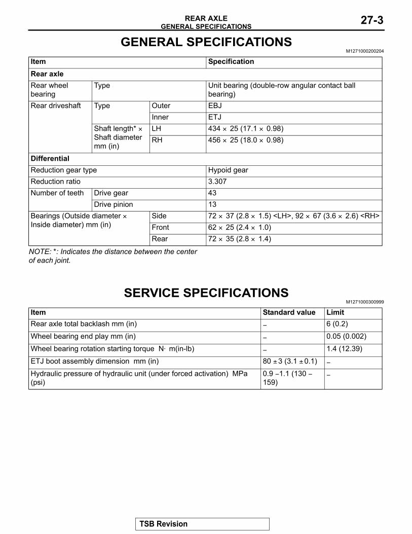
GENERAL SPECIFICATIONSM1271000200204
NOTE: *: Indicates the distance between the center of each joint.
SERVICE SPECIFICATIONSM1271000300999
Item SpecificationRear axleRear wheel bearing
Type Unit bearing (double-row angular contact ball bearing)
Rear driveshaft Type Outer EBJInner ETJ
Shaft length* × Shaft diameter mm (in)
LH 434 × 25 (17.1 × 0.98)RH 456 × 25 (18.0 × 0.98)
DifferentialReduction gear type Hypoid gearReduction ratio 3.307Number of teeth Drive gear 43
Drive pinion 13Bearings (Outside diameter × Inside diameter) mm (in)
Side 72 × 37 (2.8 × 1.5) <LH>, 92 × 67 (3.6 × 2.6) <RH>Front 62 × 25 (2.4 × 1.0)Rear 72 × 35 (2.8 × 1.4)
Item Standard value LimitRear axle total backlash mm (in) − 6 (0.2)
Wheel bearing end play mm (in) − 0.05 (0.002)
Wheel bearing rotation starting torque N⋅ m(in-lb) − 1.4 (12.39)
ETJ boot assembly dimension mm (in) 80 ± 3 (3.1 ± 0.1) −
Hydraulic pressure of hydraulic unit (under forced activation) MPa (psi)
0.9 − 1.1 (130 − 159)
−
TSB Revision
LUBRICANTSREAR AXLE27-4
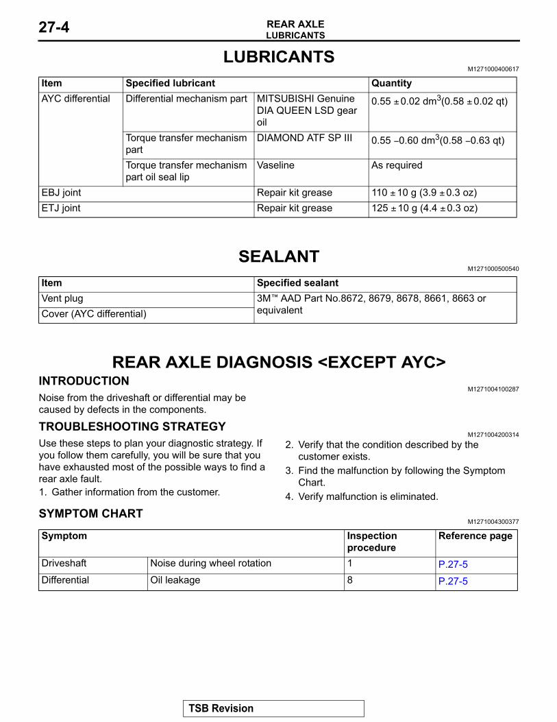
LUBRICANTSM1271000400617
SEALANTM1271000500540
REAR AXLE DIAGNOSIS <EXCEPT AYC>INTRODUCTION
M1271004100287Noise from the driveshaft or differential may be caused by defects in the components.
TROUBLESHOOTING STRATEGYM1271004200314
Use these steps to plan your diagnostic strategy. If you follow them carefully, you will be sure that you have exhausted most of the possible ways to find a rear axle fault.1. Gather information from the customer.
2. Verify that the condition described by the customer exists.
3. Find the malfunction by following the Symptom Chart.
4. Verify malfunction is eliminated.
SYMPTOM CHARTM1271004300377
Item Specified lubricant QuantityAYC differential Differential mechanism part MITSUBISHI Genuine
DIA QUEEN LSD gear oil
0.55 ± 0.02 dm3(0.58 ± 0.02 qt)
Torque transfer mechanism part
DIAMOND ATF SP III 0.55 − 0.60 dm3(0.58 − 0.63 qt)
Torque transfer mechanism part oil seal lip
Vaseline As required
EBJ joint Repair kit grease 110 ± 10 g (3.9 ± 0.3 oz)ETJ joint Repair kit grease 125 ± 10 g (4.4 ± 0.3 oz)
Item Specified sealantVent plug 3M™ AAD Part No.8672, 8679, 8678, 8661, 8663 or
equivalentCover (AYC differential)
Symptom Inspection procedure
Reference page
Driveshaft Noise during wheel rotation 1 P.27-5Differential Oil leakage 8 P.27-5
TSB Revision
REAR AXLE DIAGNOSIS <EXCEPT AYC>REAR AXLE 27-5
SYMPTOM PROCEDURES
INSPECTION PROCEDURE 1: Noise during Wheel Rotation <DRIVESHAFT>
DIAGNOSIS
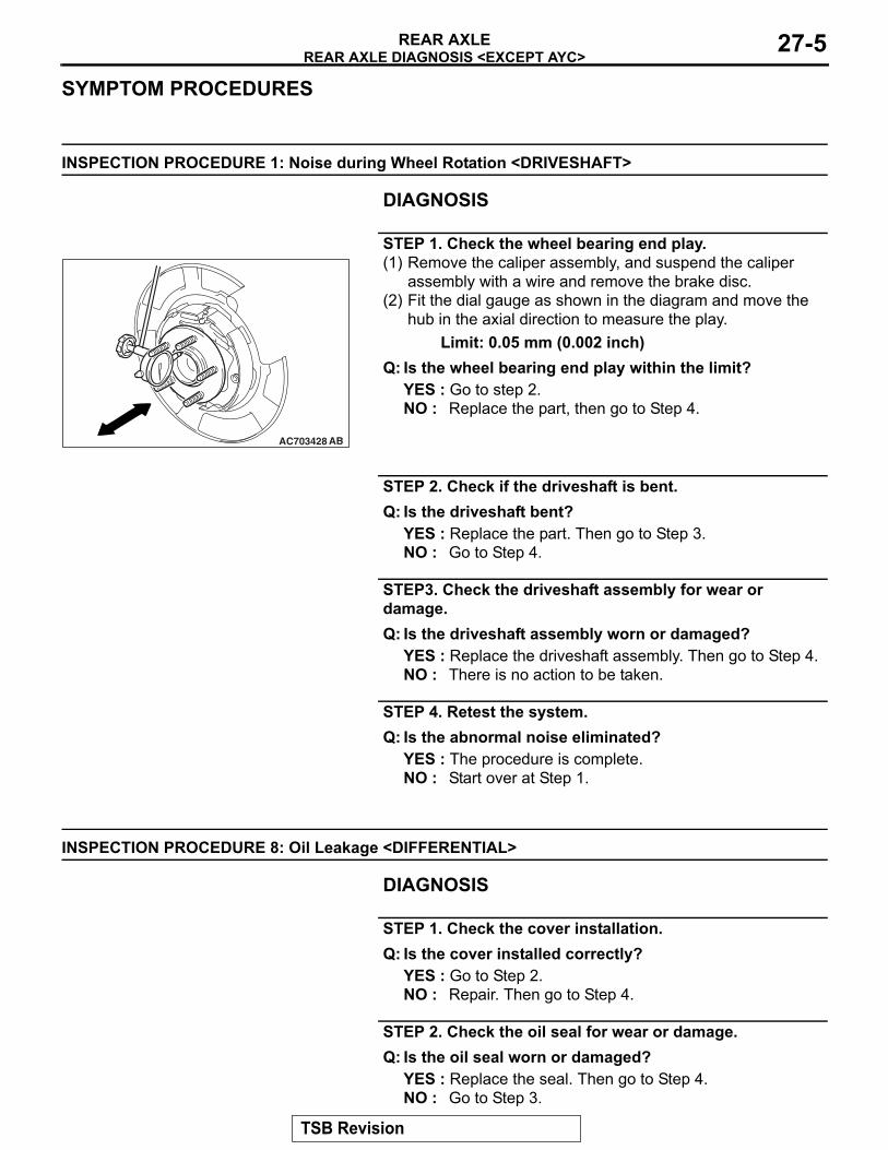
STEP 1. Check the wheel bearing end play.(1) Remove the caliper assembly, and suspend the caliper
assembly with a wire and remove the brake disc.(2) Fit the dial gauge as shown in the diagram and move the
hub in the axial direction to measure the play.Limit: 0.05 mm (0.002 inch)
Q: Is the wheel bearing end play within the limit?YES : Go to step 2.NO : Replace the part, then go to Step 4.
STEP 2. Check if the driveshaft is bent.Q: Is the driveshaft bent?
YES : Replace the part. Then go to Step 3.NO : Go to Step 4.
STEP3. Check the driveshaft assembly for wear or damage.Q: Is the driveshaft assembly worn or damaged?
YES : Replace the driveshaft assembly. Then go to Step 4.NO : There is no action to be taken.
STEP 4. Retest the system.Q: Is the abnormal noise eliminated?
YES : The procedure is complete.NO : Start over at Step 1.
INSPECTION PROCEDURE 8: Oil Leakage <DIFFERENTIAL>
DIAGNOSIS
STEP 1. Check the cover installation.Q: Is the cover installed correctly?
YES : Go to Step 2.NO : Repair. Then go to Step 4.
STEP 2. Check the oil seal for wear or damage.Q: Is the oil seal worn or damaged?
YES : Replace the seal. Then go to Step 4.NO : Go to Step 3.
AC703428 AB
TSB Revision
REAR AXLE DIAGNOSIS <AYC>REAR AXLE27-6
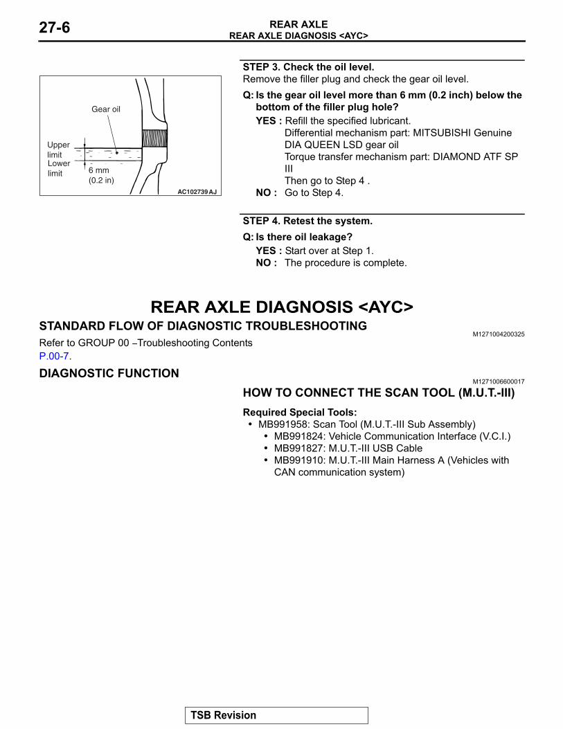
STEP 3. Check the oil level.Remove the filler plug and check the gear oil level.Q: Is the gear oil level more than 6 mm (0.2 inch) below the
bottom of the filler plug hole?YES : Refill the specified lubricant.
Differential mechanism part: MITSUBISHI Genuine DIA QUEEN LSD gear oil Torque transfer mechanism part: DIAMOND ATF SP III Then go to Step 4 .
NO : Go to Step 4.
STEP 4. Retest the system.Q: Is there oil leakage?
YES : Start over at Step 1.NO : The procedure is complete.
REAR AXLE DIAGNOSIS <AYC>STANDARD FLOW OF DIAGNOSTIC TROUBLESHOOTING
M1271004200325Refer to GROUP 00 − Troubleshooting Contents P.00-7.
DIAGNOSTIC FUNCTIONM1271006600017
HOW TO CONNECT THE SCAN TOOL (M.U.T.-III)Required Special Tools:• MB991958: Scan Tool (M.U.T.-III Sub Assembly)
• MB991824: Vehicle Communication Interface (V.C.I.)• MB991827: M.U.T.-III USB Cable• MB991910: M.U.T.-III Main Harness A (Vehicles with
CAN communication system)
AC102739
6 mm(0.2 in)
AJ
Upper limitLower limit
Gear oil
TSB Revision
REAR AXLE DIAGNOSIS <AYC>REAR AXLE 27-7
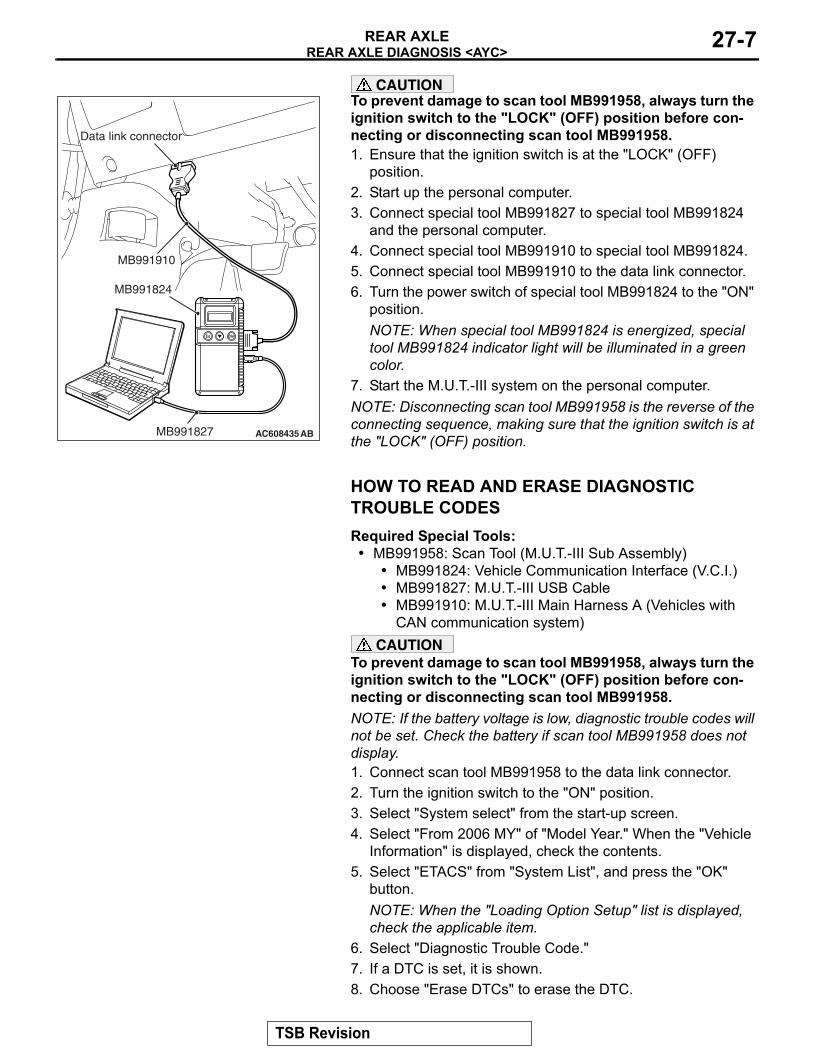
CAUTIONTo prevent damage to scan tool MB991958, always turn the ignition switch to the "LOCK" (OFF) position before con-necting or disconnecting scan tool MB991958.1. Ensure that the ignition switch is at the "LOCK" (OFF)
position.2. Start up the personal computer.3. Connect special tool MB991827 to special tool MB991824
and the personal computer.4. Connect special tool MB991910 to special tool MB991824.5. Connect special tool MB991910 to the data link connector.6. Turn the power switch of special tool MB991824 to the "ON"
position.NOTE: When special tool MB991824 is energized, special tool MB991824 indicator light will be illuminated in a green color.
7. Start the M.U.T.-III system on the personal computer.NOTE: Disconnecting scan tool MB991958 is the reverse of the connecting sequence, making sure that the ignition switch is at the "LOCK" (OFF) position.
HOW TO READ AND ERASE DIAGNOSTIC TROUBLE CODESRequired Special Tools:• MB991958: Scan Tool (M.U.T.-III Sub Assembly)
• MB991824: Vehicle Communication Interface (V.C.I.)• MB991827: M.U.T.-III USB Cable• MB991910: M.U.T.-III Main Harness A (Vehicles with
CAN communication system)CAUTION
To prevent damage to scan tool MB991958, always turn the ignition switch to the "LOCK" (OFF) position before con-necting or disconnecting scan tool MB991958.NOTE: If the battery voltage is low, diagnostic trouble codes will not be set. Check the battery if scan tool MB991958 does not display.1. Connect scan tool MB991958 to the data link connector.2. Turn the ignition switch to the "ON" position.3. Select "System select" from the start-up screen.4. Select "From 2006 MY" of "Model Year." When the "Vehicle
Information" is displayed, check the contents.5. Select "ETACS" from "System List", and press the "OK"
button.NOTE: When the "Loading Option Setup" list is displayed, check the applicable item.
6. Select "Diagnostic Trouble Code."7. If a DTC is set, it is shown.8. Choose "Erase DTCs" to erase the DTC.
AC608435
Data link connector
MB991827
MB991824
MB991910
AB
TSB Revision
REAR AXLE DIAGNOSIS <AYC>REAR AXLE27-8
DIAGNOSTIC TROUBLE CODE CHARTM1271006700014
CAUTIONDuring diagnosis, a DTC code associated with other systems may be set when the ignition switch is turned on with connector(s) disconnected. On completion, check all systems for DTCs. If DTC code(s) are set, erase them all.NOTE: Refer to GROUP 22A−Diagnostic Trouble Code Chart P.22A-12 for Others Diagnostic Trouble Code.
DTC No. Inspection item Reference pageC1619 AYC current value abnormality P.27-9C161A AYC direction valve(RH) output error P.27-12C161B AYC direction valve(LH) output error P.27-15C1620 AYC control abnormality P.27-19
TSB Revision
REAR AXLE DIAGNOSIS <AYC>REAR AXLE 27-9
INSPECTION PROCEDURE FOR DIAGNOSIS CODE
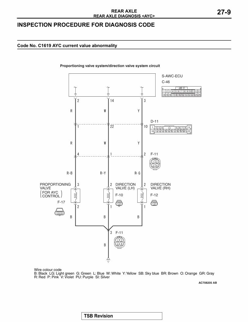
Code No. C1619 AYC current value abnormality
S-AWC-ECU
DIRECTIONVALVE (LH)
DIRECTIONVALVE (RH)
PROPORTIONINGVALVE
FOR AYCCONTROL
AC708205
Proportioning valve system/direction valve system circuit
Wire colour codeB: Black LG: Light green G: Green L: Blue W: White Y: Yellow SB: Sky blue BR: Brown O: Orange GR: GrayR: Red P: Pink V: Violet PU: Purple SI: Silver
AB
C-46
D-11
F-11
F-12F-10
F-17
F-11
TSB Revision
REAR AXLE DIAGNOSIS <AYC>REAR AXLE27-10
CAUTIONIf there is any problem in the CAN bus lines, an incorrect diagnostic trouble code may be set. Prior to this diagnosis, diagnose the CAN bus lines..
OPERATION• The power from AWC-ECU is supplied to and
energizes the hydraulic unit AYC proportioning valve solenoid.
.
FUNCTION• The AWC-ECU controls the specified current of
the coil for the hydraulic unit AYC proportioning valve solenoid.
• The hydraulic unit AYC proportioning valve sole-noid controls the hydraulic pressure to the AYC differential right/left clutch.
.
TROUBLE JUDGMENTRange of check
• The output to the AYC proportioning valve sole-noid is 0.05 A or more.
• The DTC related to the power supply circuit is not set.
JUDGMENT CRITERIA• The current monitor value of the AYC proportion-
ing valve solenoid is abnormal.
Fail-safe, backup function• AWC-ECU suspends the AYC control and illumi-
nates the multi-information display. Then DTC No. C1619 is set.
.
PROBABLE CAUSES• Malfunction inside the AYC proportioning valve
solenoid• Damaged harness wires and connectors
• Open circuit, short to ground, and connector continuity failure between the AWC-ECU and the AYC proportioning valve solenoid
• Open circuit and connector continuity failure between the AYC proportioning valve sole-noid and the body ground
• Malfunction inside the AWC-ECU
DIAGNOSTIC PROCEDURE
STEP 1. Scan tool CAN bus diagnosticsUsing the scan tool, diagnose the CAN bus lines.
Q: Is the check result normal?YES : Go to Step 3.NO : Repair the CAN bus line (Refer to GROUP
54C − Troubleshooting P.54C-15). After repairing the CAN bus line, go to Step 2.
STEP 2. DTC recheck after repairing the CAN bus line(1) Erase the DTC.(2) Turn the ignition switch from the LOCK (OFF)
position to the ON position, and then wait for 4 seconds.
(3) Check if the DTC is set.
Q: Is DTC No. C1619 set?YES : Go to Step 3.NO : This diagnosis is complete.
AC708196
AC708214Connector: C-46
AB
AC706034 AB
Connector: D-11
AC706035 AB
F-11
Connector: F-11, F-17Body earth: No.9
F-17 (B)
No.9
TSB Revision
REAR AXLE DIAGNOSIS <AYC>REAR AXLE 27-11
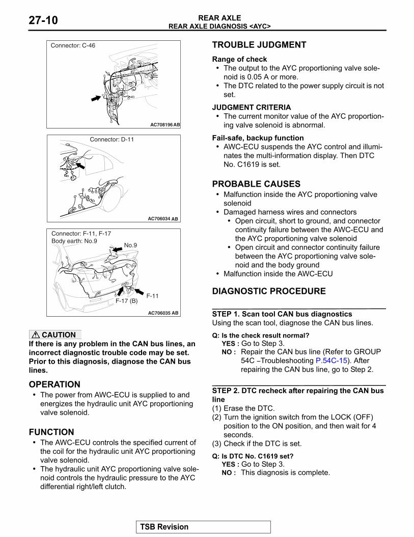
STEP 3. Connector check:Check the connectors below for improper engage-ment, terminal damage or terminal drawn in the con-nector case.• C-46 AWC-ECU connector• F-17 AYC proportioning valve connector• D-11 intermediate connector, F-11 intermediate
connector• No. 9 body ground
Q: Are the connectors and terminals in good condition?YES : Go to Step 4.NO : Repair the faulty connector(s) or terminal(s).
Then go to Step 8.
STEP 4. Harness check(1) Check the wiring harness among C-46
AWC-ECU connector (terminal No. 2), D-11 intermediate connector (terminal No. 1), F-11 intermediate connector (terminal No. 4), and F-17 AYC proportioning valve connector (terminal No. 3) for any problems.
(2) Check the wiring harness among F-17 AYC proportioning valve connector (terminal No. 2), F-11 intermediate connector (terminal No. 3), and No. 9 body ground for any problems.
Q: Is the harness in good condition?YES : Go to Step 5.NO : Repair the problem in the wiring harness.
Then go to Step 8.
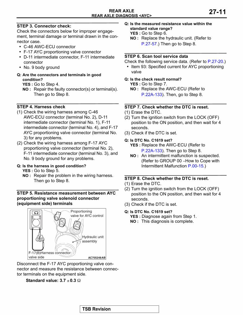
STEP 5. Resistance measurement between AYC proportioning valve solenoid connector (equipment side) terminals
Disconnect the F-17 AYC proportioning valve con-nector and measure the resistance between connec-tor terminals on the equipment side.
Standard value: 3.7 ± 0.3 Ω
Q: Is the measured resistance value within the standard value range?YES : Go to Step 6.NO : Replace the hydraulic unit. (Refer to
P.27-57.) Then go to Step 8.
STEP 6. Scan tool service dataCheck the following service data. (Refer to P.27-20.)
• Item 93: Specified current for AYC proportioning valve
Q: Is the check result normal?YES : Go to Step 7.NO : Replace the AWC-ECU (Refer to
P.22A-133). Then, go to Step 8.
STEP 7. Check whether the DTC is reset.(1) Erase the DTC.(2) Turn the ignition switch from the LOCK (OFF)
position to the ON position, and then wait for 4 seconds.
(3) Check if the DTC is set.
Q: Is DTC No. C1619 set?YES : Replace the AWC-ECU (Refer to
P.22A-133). Then go to Step 8.NO : An intermittent malfunction is suspected.
(Refer to GROUP 00 − How to Cope with Intermittent Malfunction P.00-15.)
STEP 8. Check whether the DTC is reset.(1) Erase the DTC.(2) Turn the ignition switch from the LOCK (OFF)
position to the ON position, and then wait for 4 seconds.
(3) Check if the DTC is set.
Q: Is DTC No. C1619 set?YES : Diagnose again from Step 1.NO : This diagnosis is complete.
AC705248AB
Hydraulic unitassembly
Proportioningvalve for AYC control
F-17(B)Harness connector:valve side
TSB Revision
REAR AXLE DIAGNOSIS <AYC>REAR AXLE27-12
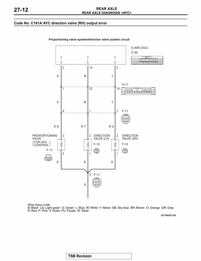
Code No. C161A AYC direction valve (RH) output error
S-AWC-ECU
DIRECTIONVALVE (LH)
DIRECTIONVALVE (RH)
PROPORTIONINGVALVE
FOR AYCCONTROL
AC708205
Proportioning valve system/direction valve system circuit
Wire colour codeB: Black LG: Light green G: Green L: Blue W: White Y: Yellow SB: Sky blue BR: Brown O: Orange GR: GrayR: Red P: Pink V: Violet PU: Purple SI: Silver
AB
C-46
D-11
F-11
F-12F-10
F-17
F-11
TSB Revision
REAR AXLE DIAGNOSIS <AYC>REAR AXLE 27-13
CAUTIONIf there is any problem in the CAN bus lines, an incorrect diagnostic trouble code may be set. Prior to this diagnosis, diagnose the CAN bus lines..
OPERATION• The power from AWC-ECU is supplied to and
energizes the hydraulic unit AYC direction valve (RH) solenoid.
.
FUNCTION• The AWC-ECU controls the activation command
of the coil for the hydraulic unit AYC direction valve (RH) solenoid.
• The hydraulic unit AYC direction valve (RH) sole-noid controls the hydraulic pressure to the AYC differential right clutch.
.
TROUBLE JUDGMENTRange of check
• The DTC related to the power supply circuit is not set.
JUDGMENT CRITERIA• The activation command of the AYC direction
valve (RH) solenoid is different from that shown on the monitor.
Fail-safe, backup function• The AWC-ECU suspends the AYC control and
illuminates the multi-information display. Then DTC No. C161A is set.
.
PROBABLE CAUSES• Malfunction inside the AYC direction valve (RH)
solenoid• Damaged harness wires and connectors
• Open circuit, short to ground, and connector continuity failure between AWC-ECU and AYC direction valve (RH) solenoid
• Open circuit and connector continuity failure between the AYC direction valve (RH) sole-noid and the body ground
• Malfunction inside the AWC-ECU
DIAGNOSTIC PROCEDURE
STEP 1. Scan tool CAN bus diagnosticsUsing the scan tool, diagnose the CAN bus lines.
Q: Is the check result normal?YES : Go to Step 3.NO : Repair the CAN bus line (Refer to GROUP
54C − Troubleshooting P.54C-15). After repairing the CAN bus line, go to Step 2.
STEP 2. DTC recheck after repairing the CAN bus line(1) Erase the DTC.(2) Turn the ignition switch from the LOCK (OFF)
position to the ON position, and then wait for 4 seconds.
(3) Using the scan tool, apply the specified current to the AYC proportioning valve, and forcibly activate the AYC direction valve (RH). (Refer to Actuator Test Table P.27-20.)
(4) Check if the DTC is set.
Q: Is DTC No. C161A set?YES : Go to Step 3.NO : This diagnosis is complete.
AC708196
AC708214Connector: C-46
AB
AC706034 AB
Connector: D-11
AC706035 AC
F-11
Connector: F-11, F-12Body earth: No.9
F-12(B)
No.9
TSB Revision
REAR AXLE DIAGNOSIS <AYC>REAR AXLE27-14
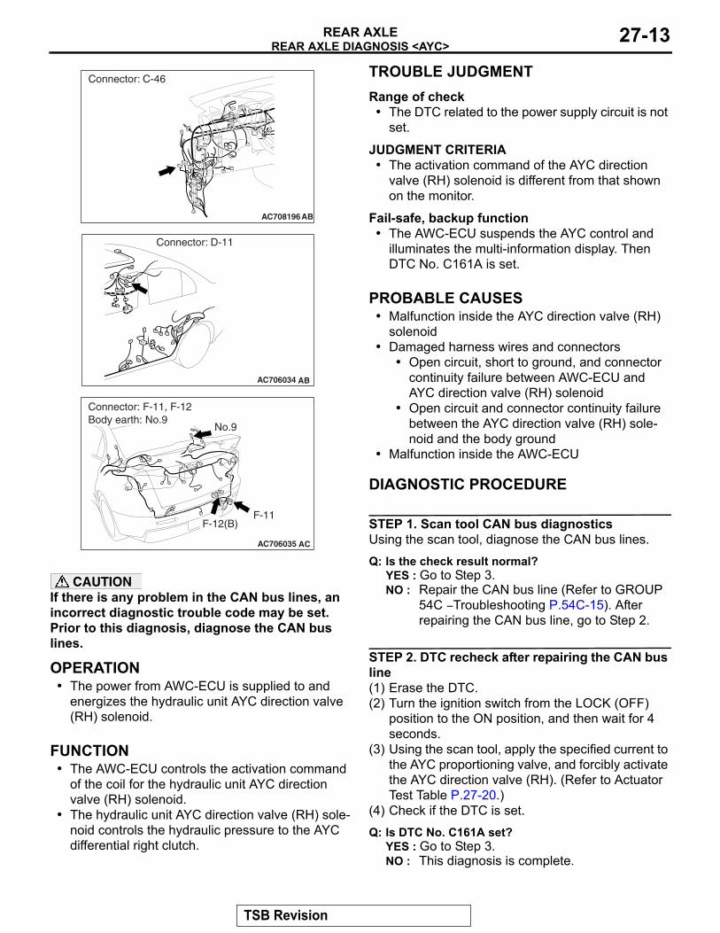
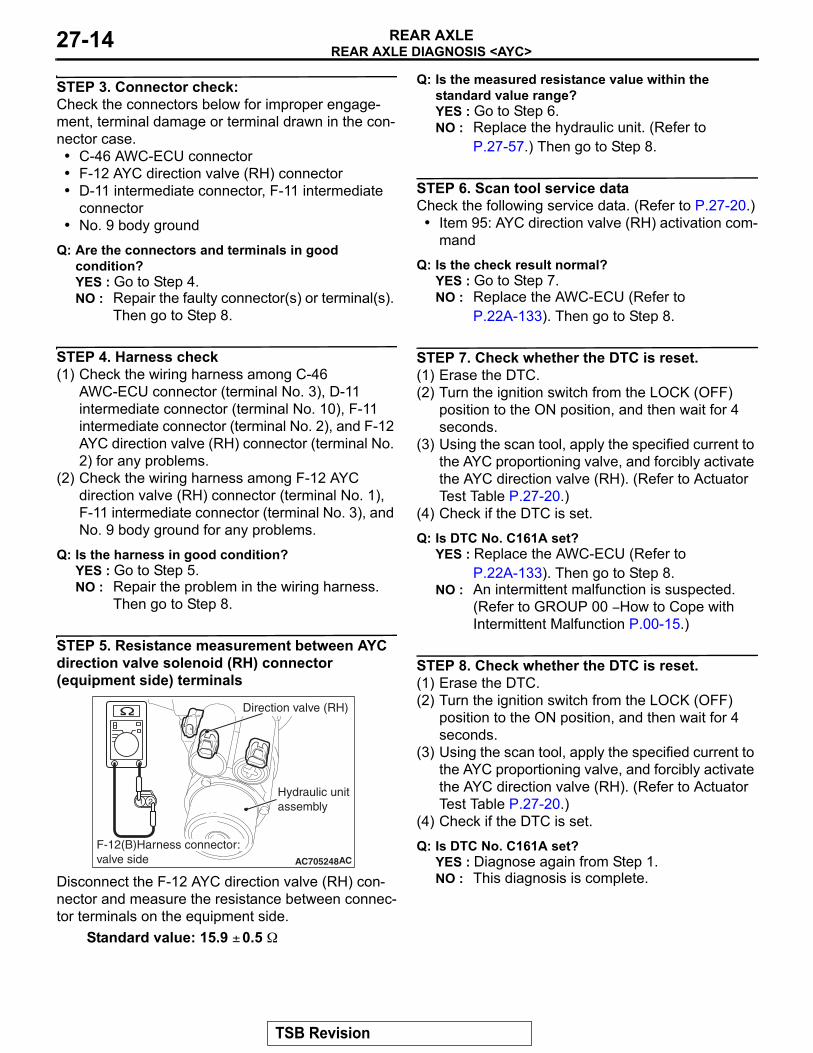
STEP 3. Connector check:Check the connectors below for improper engage-ment, terminal damage or terminal drawn in the con-nector case.• C-46 AWC-ECU connector• F-12 AYC direction valve (RH) connector• D-11 intermediate connector, F-11 intermediate
connector• No. 9 body ground
Q: Are the connectors and terminals in good condition?YES : Go to Step 4.NO : Repair the faulty connector(s) or terminal(s).
Then go to Step 8.
STEP 4. Harness check(1) Check the wiring harness among C-46
AWC-ECU connector (terminal No. 3), D-11 intermediate connector (terminal No. 10), F-11 intermediate connector (terminal No. 2), and F-12 AYC direction valve (RH) connector (terminal No. 2) for any problems.
(2) Check the wiring harness among F-12 AYC direction valve (RH) connector (terminal No. 1), F-11 intermediate connector (terminal No. 3), and No. 9 body ground for any problems.
Q: Is the harness in good condition?YES : Go to Step 5.NO : Repair the problem in the wiring harness.
Then go to Step 8.
STEP 5. Resistance measurement between AYC direction valve solenoid (RH) connector (equipment side) terminals
Disconnect the F-12 AYC direction valve (RH) con-nector and measure the resistance between connec-tor terminals on the equipment side.
Standard value: 15.9 ± 0.5 Ω
Q: Is the measured resistance value within the standard value range?YES : Go to Step 6.NO : Replace the hydraulic unit. (Refer to
P.27-57.) Then go to Step 8.
STEP 6. Scan tool service dataCheck the following service data. (Refer to P.27-20.)
• Item 95: AYC direction valve (RH) activation com-mand
Q: Is the check result normal?YES : Go to Step 7.NO : Replace the AWC-ECU (Refer to
P.22A-133). Then go to Step 8.
STEP 7. Check whether the DTC is reset.(1) Erase the DTC.(2) Turn the ignition switch from the LOCK (OFF)
position to the ON position, and then wait for 4 seconds.
(3) Using the scan tool, apply the specified current to the AYC proportioning valve, and forcibly activate the AYC direction valve (RH). (Refer to Actuator Test Table P.27-20.)
(4) Check if the DTC is set.
Q: Is DTC No. C161A set?YES : Replace the AWC-ECU (Refer to
P.22A-133). Then go to Step 8.NO : An intermittent malfunction is suspected.
(Refer to GROUP 00 − How to Cope with Intermittent Malfunction P.00-15.)
STEP 8. Check whether the DTC is reset.(1) Erase the DTC.(2) Turn the ignition switch from the LOCK (OFF)
position to the ON position, and then wait for 4 seconds.
(3) Using the scan tool, apply the specified current to the AYC proportioning valve, and forcibly activate the AYC direction valve (RH). (Refer to Actuator Test Table P.27-20.)
(4) Check if the DTC is set.
Q: Is DTC No. C161A set?YES : Diagnose again from Step 1.NO : This diagnosis is complete.
AC705248AC
F-12(B)Harness connector:valve side
Hydraulic unitassembly
Direction valve (RH)
TSB Revision
REAR AXLE DIAGNOSIS <AYC>REAR AXLE 27-15
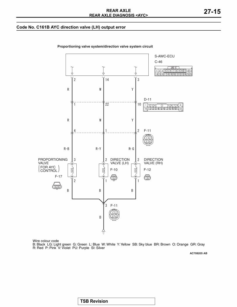
Code No. C161B AYC direction valve (LH) output error
S-AWC-ECU
DIRECTIONVALVE (LH)
DIRECTIONVALVE (RH)
PROPORTIONINGVALVE
FOR AYCCONTROL
AC708205
Proportioning valve system/direction valve system circuit
Wire colour codeB: Black LG: Light green G: Green L: Blue W: White Y: Yellow SB: Sky blue BR: Brown O: Orange GR: GrayR: Red P: Pink V: Violet PU: Purple SI: Silver
AB
C-46
D-11
F-11
F-12F-10
F-17
F-11
TSB Revision
REAR AXLE DIAGNOSIS <AYC>REAR AXLE27-16
CAUTIONIf there is any problem in the CAN bus lines, an incorrect diagnostic trouble code may be set. Prior to this diagnosis, diagnose the CAN bus lines..
OPERATION• The power from AWC-ECU is supplied to and
energizes the hydraulic unit AYC direction valve (LH) solenoid.
.
FUNCTION• The AWC-ECU controls the activation command
of the coil for the hydraulic unit AYC direction valve (LH) solenoid.
• The hydraulic unit AYC direction valve (LH) sole-noid controls the hydraulic pressure to the AYC differential left clutch.
.
TROUBLE JUDGMENTRange of check
• The DTC related to the power supply circuit is not set.
JUDGMENT CRITERIA• The activation command of the AYC direction
valve (LH) solenoid is different from that shown on the monitor.
Fail-safe, backup function• The AWC-ECU suspends the AYC control and
illuminates the multi-information display. Then DTC No. C161B is set.
.
PROBABLE CAUSES• Malfunction inside the AYC direction valve (LH)
solenoid• Damaged harness wires and connectors
• Open circuit, short to ground, and connector continuity failure between AWC-ECU and AYC direction valve (LH) solenoid
• Open circuit and connector continuity failure between the AYC direction valve (LH) sole-noid and the body ground
• Malfunction inside the AWC-ECU
DIAGNOSTIC PROCEDURE
STEP 1. Scan tool CAN bus diagnosticsUsing the scan tool, diagnose the CAN bus lines.
Q: Is the check result normal?YES : Go to Step 3.NO : Repair the CAN bus line (Refer to GROUP
54C − Troubleshooting P.54C-15). After repairing the CAN bus line, go to Step 2.
STEP 2. DTC recheck after repairing the CAN bus line(1) Erase the DTC.(2) Turn the ignition switch from the LOCK (OFF)
position to the ON position, and then wait for 4 seconds.
(3) Using the scan tool, apply the specified current to the AYC proportioning valve, and forcibly activate the AYC direction valve (LH). (Refer to Actuator Test Table P.27-20.)
(4) Check if the DTC is set.
Q: Is DTC No. C161B set?YES : Go to Step 3.NO : This diagnosis is complete.
AC708196
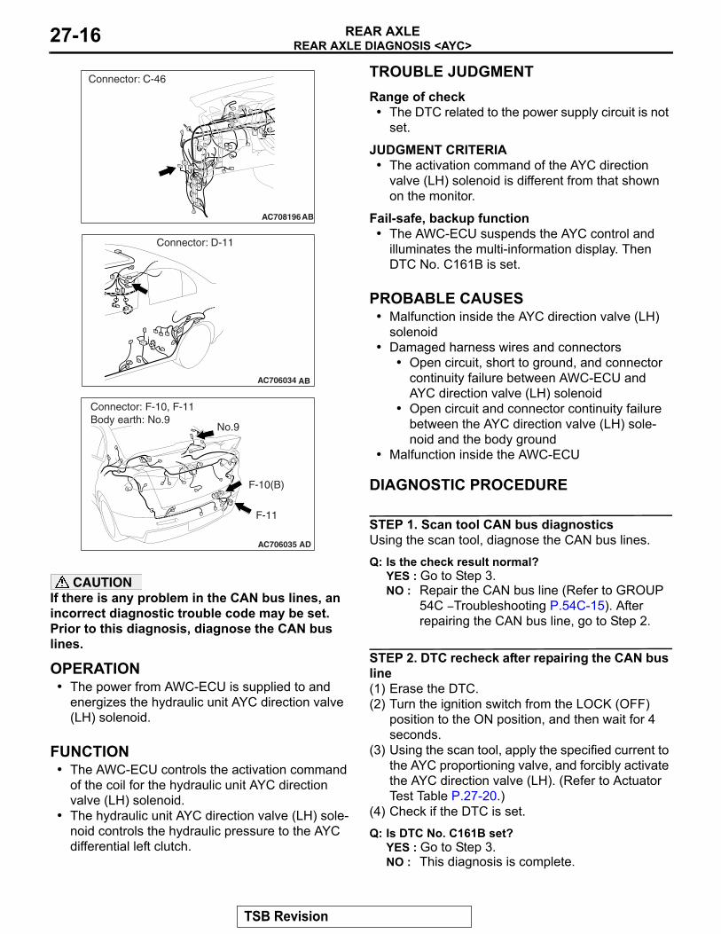
AC708214Connector: C-46
AB
AC706034 AB
Connector: D-11
AC706035 AD
F-10(B)
F-11
Connector: F-10, F-11Body earth: No.9
No.9
TSB Revision
REAR AXLE DIAGNOSIS <AYC>REAR AXLE 27-17
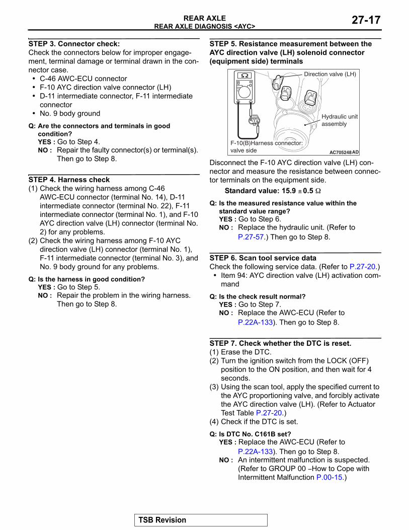
STEP 3. Connector check:Check the connectors below for improper engage-ment, terminal damage or terminal drawn in the con-nector case.• C-46 AWC-ECU connector• F-10 AYC direction valve connector (LH)• D-11 intermediate connector, F-11 intermediate
connector• No. 9 body ground
Q: Are the connectors and terminals in good condition?YES : Go to Step 4.NO : Repair the faulty connector(s) or terminal(s).
Then go to Step 8.
STEP 4. Harness check(1) Check the wiring harness among C-46
AWC-ECU connector (terminal No. 14), D-11 intermediate connector (terminal No. 22), F-11 intermediate connector (terminal No. 1), and F-10 AYC direction valve (LH) connector (terminal No. 2) for any problems.
(2) Check the wiring harness among F-10 AYC direction valve (LH) connector (terminal No. 1), F-11 intermediate connector (terminal No. 3), and No. 9 body ground for any problems.
Q: Is the harness in good condition?YES : Go to Step 5.NO : Repair the problem in the wiring harness.
Then go to Step 8.
STEP 5. Resistance measurement between the AYC direction valve (LH) solenoid connector (equipment side) terminals
Disconnect the F-10 AYC direction valve (LH) con-nector and measure the resistance between connec-tor terminals on the equipment side.
Standard value: 15.9 ± 0.5 ΩQ: Is the measured resistance value within the
standard value range?YES : Go to Step 6.NO : Replace the hydraulic unit. (Refer to
P.27-57.) Then go to Step 8.
STEP 6. Scan tool service dataCheck the following service data. (Refer to P.27-20.)
• Item 94: AYC direction valve (LH) activation com-mand
Q: Is the check result normal?YES : Go to Step 7.NO : Replace the AWC-ECU (Refer to
P.22A-133). Then go to Step 8.
STEP 7. Check whether the DTC is reset.(1) Erase the DTC.(2) Turn the ignition switch from the LOCK (OFF)
position to the ON position, and then wait for 4 seconds.
(3) Using the scan tool, apply the specified current to the AYC proportioning valve, and forcibly activate the AYC direction valve (LH). (Refer to Actuator Test Table P.27-20.)
(4) Check if the DTC is set.
Q: Is DTC No. C161B set?YES : Replace the AWC-ECU (Refer to
P.22A-133). Then go to Step 8.NO : An intermittent malfunction is suspected.
(Refer to GROUP 00 − How to Cope with Intermittent Malfunction P.00-15.)
AC705248AD
F-10(B)Harness connector:valve side
Hydraulic unitassembly
Direction valve (LH)
TSB Revision
REAR AXLE DIAGNOSIS <AYC>REAR AXLE27-18
STEP 8. Check whether the DTC is reset.(1) Erase the DTC.(2) Turn the ignition switch from the LOCK (OFF)
position to the ON position, and then wait for 4 seconds.
(3) Using the scan tool, apply the specified current to the AYC proportioning valve, and forcibly activate the AYC direction valve (LH). (Refer to Actuator Test Table P.27-20.)
(4) Check if the DTC is set.
Q: Is DTC No. C161B set?YES : Diagnose again from Step 1.NO : This diagnosis is complete.
Code No. C1620 AYC control abnormality
CAUTIONIf there is any problem in the CAN bus lines, an incorrect diagnostic trouble code may be set. Prior to this diagnosis, diagnose the CAN bus lines..
OPERATION• The power from AWC-ECU is supplied to and
energizes the hydraulic unit AYC proportioning valve and direction valve (RH/LH) solenoid.
.
FUNCTION• The AWC-ECU controls the specified current of
the coil for the hydraulic unit AYC proportioning valve solenoid, and activation command of the coil for the AYC direction valve (RH/LH) solenoid.
• The hydraulic unit AYC proportioning valve and direction valve (RH/LH) solenoid control the hydraulic pressure to the AYC differential right/left clutch.
.
TROUBLE JUDGMENTRange of check• The forced activation of actuator is not underway.• The output to the AYC proportioning valve sole-
noid is 0.05 A or more.
JUDGMENT CRITERIA• Due to the AYC differential clutch protection, DTC
No. C161F is set.
• The AYC proportioning valve solenoid is ener-gized longer than the specified duration.
Fail-safe, backup function• The AWC-ECU suspends the AYC control and
illuminates the multi-information display. Then DTC No. C1620 is set.
.
PROBABLE CAUSES• The driving and road conditions are severe.• Malfunction inside the AWC-ECU
DIAGNOSTIC PROCEDURE
STEP 1. CAN bus diagnostics using the scan toolUsing the scan tool, diagnose the CAN bus lines.
Q: Is the check result normal?YES : Go to Step 3.NO : Repair the CAN bus line (Refer to GROUP
54C − Troubleshooting P.54C-15). After repairing the CAN bus line, go to Step 2.
STEP 2. DTC recheck after repairing the CAN bus line(1) Erase the DTC.(2) Turn the ignition switch from the LOCK (OFF)
position to the ON position.(3) Check if the DTC is set.
Q: Is DTC No. C1620 set?YES : Go to Step 3.NO : This diagnosis is complete.
TSB Revision
REAR AXLE DIAGNOSIS <AYC>REAR AXLE 27-19
STEP 3. Check whether the DTC is reset.(1) Erase the DTC.(2) Turn the ignition switch from the LOCK (OFF)
position to the ON position.(3) Check if the DTC is set.
Q: Is DTC No. C1620 set?YES : Replace the AWC-ECU (refer to
P.22A-133), and check that another DTC is not set. Then go to Step 4.
NO : This diagnosis is complete. Under the driving and road conditions where the AYC control is operated long time (e.g.: long time cornering), the clutch protection is operated.
STEP 4. Check whether the DTC is reset.(1) Erase the DTC.(2) Turn the ignition switch from the LOCK (OFF)
position to the ON position.
Q: Is DTC No. C1620 set?YES : Diagnose again from Step 1.NO : This diagnosis is complete.
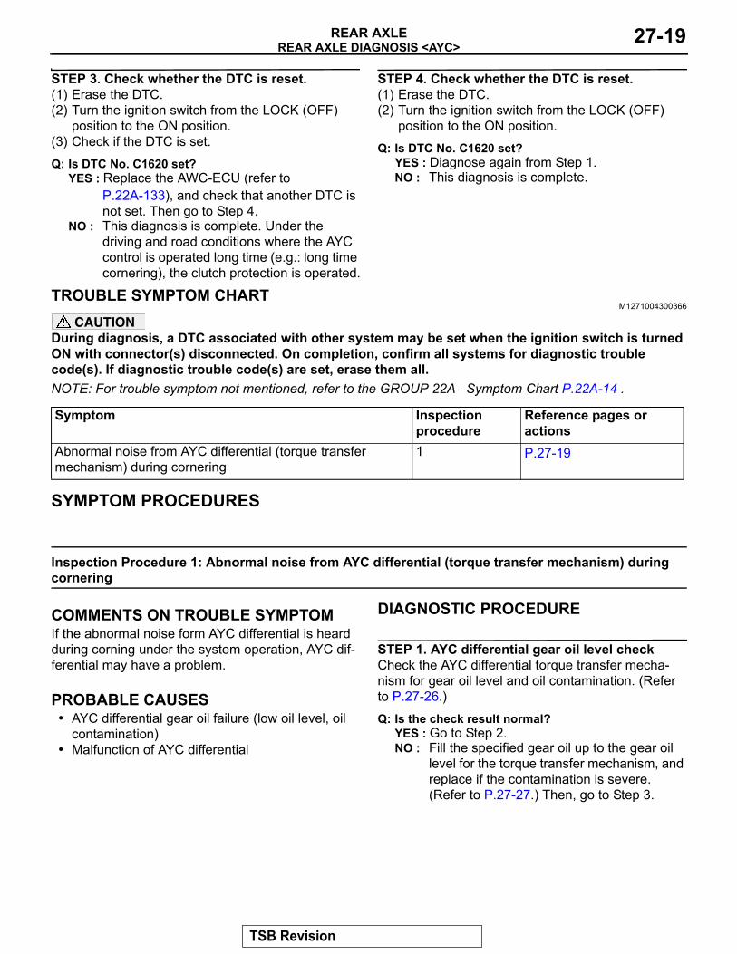
TROUBLE SYMPTOM CHARTM1271004300366
CAUTIONDuring diagnosis, a DTC associated with other system may be set when the ignition switch is turned ON with connector(s) disconnected. On completion, confirm all systems for diagnostic trouble code(s). If diagnostic trouble code(s) are set, erase them all.NOTE: For trouble symptom not mentioned, refer to the GROUP 22A − Symptom Chart P.22A-14 .
SYMPTOM PROCEDURES
Inspection Procedure 1: Abnormal noise from AYC differential (torque transfer mechanism) during cornering
.
COMMENTS ON TROUBLE SYMPTOMIf the abnormal noise form AYC differential is heard during corning under the system operation, AYC dif-ferential may have a problem..
PROBABLE CAUSES• AYC differential gear oil failure (low oil level, oil
contamination)• Malfunction of AYC differential
DIAGNOSTIC PROCEDURE
STEP 1. AYC differential gear oil level checkCheck the AYC differential torque transfer mecha-nism for gear oil level and oil contamination. (Refer to P.27-26.)
Q: Is the check result normal?YES : Go to Step 2.NO : Fill the specified gear oil up to the gear oil
level for the torque transfer mechanism, and replace if the contamination is severe. (Refer to P.27-27.) Then, go to Step 3.
Symptom Inspection procedure
Reference pages or actions
Abnormal noise from AYC differential (torque transfer mechanism) during cornering
1 P.27-19
TSB Revision
REAR AXLE DIAGNOSIS <AYC>REAR AXLE27-20
STEP 2. Check of AYC reoperationUsing the scan tool, check the AYC operation under forced activation. (Refer to P.27-30.)
Q: Does a malfunction take place again?YES : Replace the AYC differential. (Refer to
P.27-51.) Then, go to Step 3.NO : This diagnosis is complete.
STEP 3. Check of AYC reoperationUsing the scan tool, check the AYC operation under forced activation. (Refer to P.27-30.)
Q: Does a malfunction take place again?YES : Diagnose again from Step 1.NO : This diagnosis is complete.
DATA LIST REFERENCE TABLEM1271006900018
Refer to GROUP 22A − Data List Reference Table P.22A-107 Contents.
ACTUATOR TEST REFERENCE TABLEM1271007000018
Refer to GROUP 22A − Actuator Test Reference Table P.22A-114 Contents.
CHECK AT AWC-ECUM1271007200012
Refer to GROUP 22A − Check at AWC-ECU Terminal Voltage P.22A-116 Contents.
TSB Revision
SPECIAL TOOLREAR AXLE 27-21
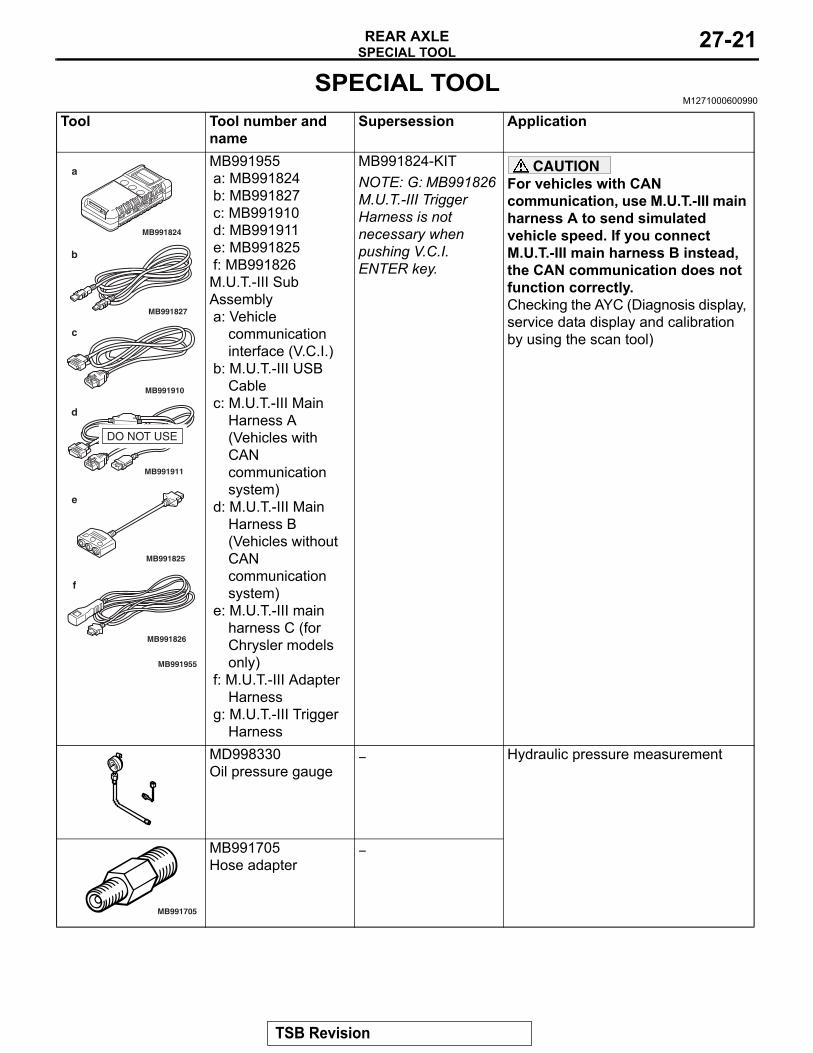
SPECIAL TOOLM1271000600990
Tool Tool number and name
Supersession Application
MB991955a: MB991824b: MB991827c: MB991910d: MB991911e: MB991825f: MB991826M.U.T.-III Sub Assemblya: Vehicle
communication interface (V.C.I.)
b: M.U.T.-III USB Cable
c: M.U.T.-III Main Harness A (Vehicles with CAN communication system)
d: M.U.T.-III Main Harness B (Vehicles without CAN communication system)
e: M.U.T.-III main harness C (for Chrysler models only)
f: M.U.T.-III Adapter Harness
g: M.U.T.-III Trigger Harness
MB991824-KITNOTE: G: MB991826 M.U.T.-III Trigger Harness is not necessary when pushing V.C.I. ENTER key.
CAUTIONFor vehicles with CAN communication, use M.U.T.-III main harness A to send simulated vehicle speed. If you connect M.U.T.-III main harness B instead, the CAN communication does not function correctly.Checking the AYC (Diagnosis display, service data display and calibration by using the scan tool)
MD998330Oil pressure gauge
− Hydraulic pressure measurement
MB991705Hose adapter
−
MB991910
MB991826
MB991955
MB991911
MB991824
MB991827
MB991825
a
b
c
d
e
f
DO NOT USE
MB991705
TSB Revision
SPECIAL TOOLREAR AXLE27-22
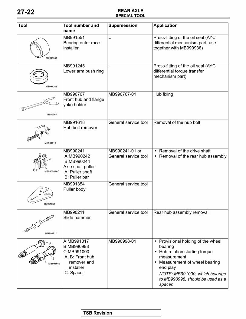
MB991551Bearing outer race installer
− Press-fitting of the oil seal (AYC differential mechanism part: use together with MB990938)
MB991245Lower arm bush ring
− Press-fitting of the oil seal (AYC differential torque transfer mechanism part)
MB990767Front hub and flange yoke holder
MB990767-01 Hub fixing
MB991618Hub bolt remover
General service tool Removal of the hub bolt
MB990241A:MB990242B:MB990244Axle shaft pullerA: Puller shaftB: Puller bar
MB990241-01 or General service tool
• Removal of the drive shaft• Removal of the rear hub assembly
MB991354Puller body
General service tool
MB990211Slide hammer
General service tool Rear hub assembly removal
A:MB991017B:MB990998C:MB991000A, B: Front hub
remover and installer
C: Spacer
MB990998-01 • Provisional holding of the wheel bearing
• Hub rotation starting torque measurement
• Measurement of wheel bearing end playNOTE: MB991000, which belongs to MB990998, should be used as a spacer.
Tool Tool number and name
Supersession Application
MB991551
MB991245
B990767
MB991618
MB990241AD
B
A
MB991354
MB990211
A
BC
MB991017
TSB Revision
SPECIAL TOOLREAR AXLE 27-23
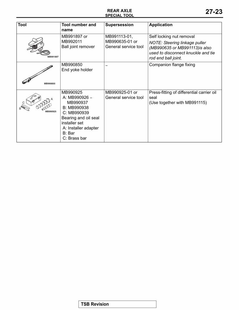
MB991897 or MB992011Ball joint remover
MB991113-01, MB990635-01 or General service tool
Self locking nut removalNOTE: Steering linkage puller (MB990635 or MB991113)is also used to disconnect knuckle and tie rod end ball joint.
MB990850End yoke holder
− Companion flange fixing
MB990925A: MB990926 −
MB990937B: MB990938C: MB990939Bearing and oil seal installer setA: Installer adapterB: BarC: Brass bar
MB990925-01 or General service tool
Press-fitting of differential carrier oil seal(Use together with MB991115)
Tool Tool number and name
Supersession Application
MB991897
MB990850
MB990925
A
B
C
TSB Revision
SPECIAL TOOLREAR AXLE27-24
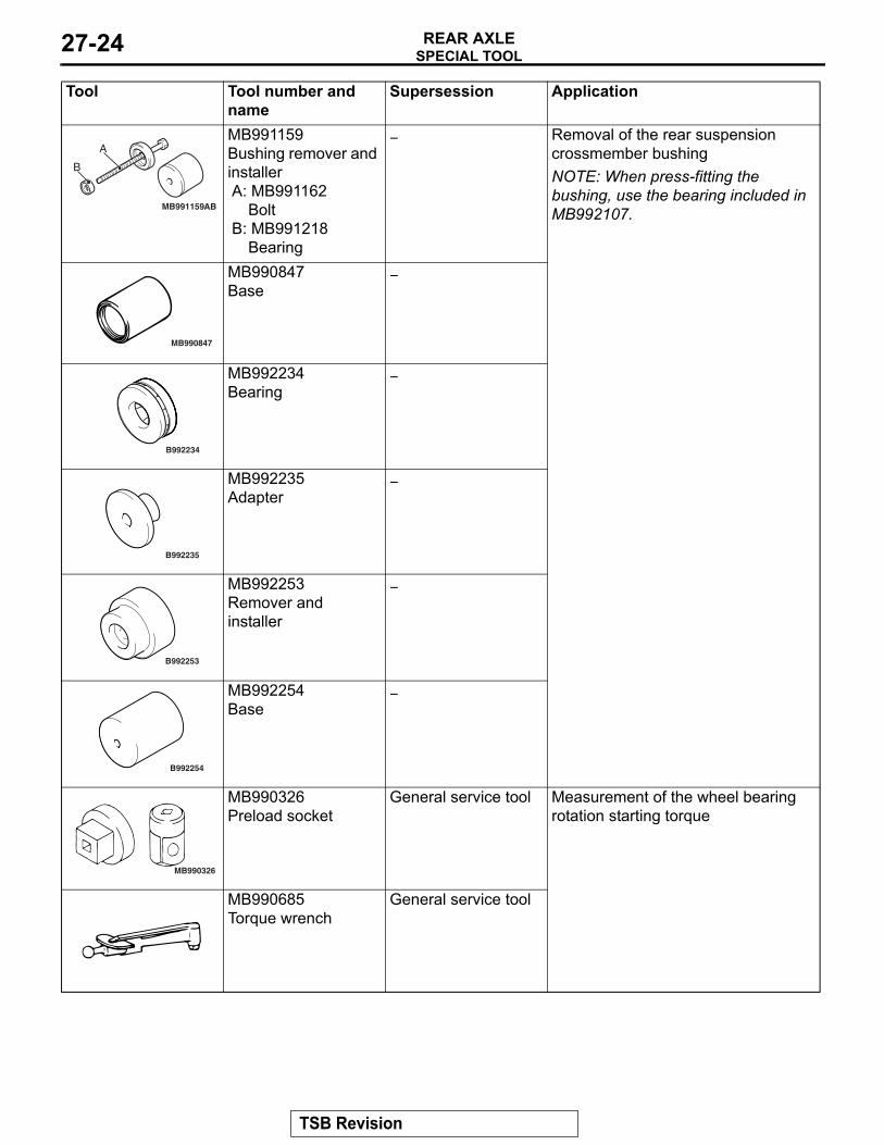
MB991159Bushing remover and installerA: MB991162
BoltB: MB991218
Bearing
− Removal of the rear suspension crossmember bushingNOTE: When press-fitting the bushing, use the bearing included in MB992107.
MB990847Base
−
MB992234Bearing
−
MB992235Adapter
−
MB992253Remover and installer
−
MB992254Base
−
MB990326Preload socket
General service tool Measurement of the wheel bearing rotation starting torque
MB990685Torque wrench
General service tool
Tool Tool number and name
Supersession Application
MB991159AB
A
B
MB990847
B992234
B992235
B992253
B992254
MB990326
TSB Revision
ON-VEHICLE SERVICEREAR AXLE 27-25
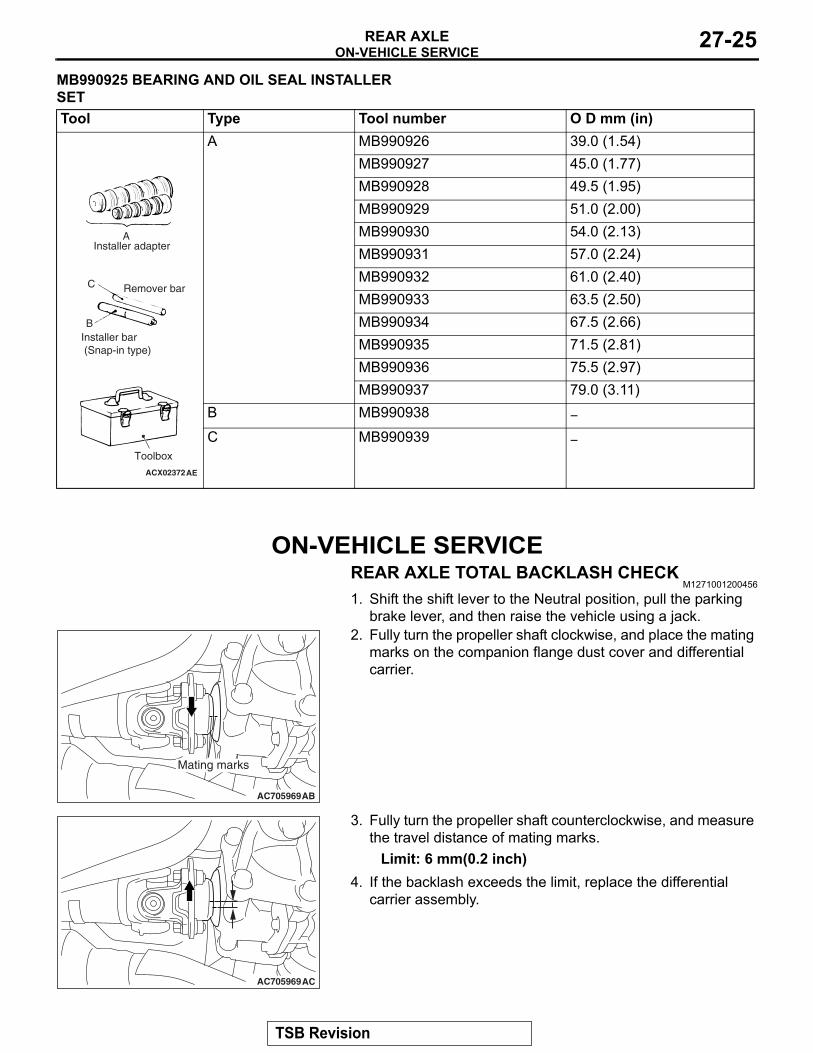
MB990925 BEARING AND OIL SEAL INSTALLER SET
ON-VEHICLE SERVICEREAR AXLE TOTAL BACKLASH CHECK
M1271001200456
1. Shift the shift lever to the Neutral position, pull the parking brake lever, and then raise the vehicle using a jack.
2. Fully turn the propeller shaft clockwise, and place the mating marks on the companion flange dust cover and differential carrier.
3. Fully turn the propeller shaft counterclockwise, and measure the travel distance of mating marks.
Limit: 6 mm(0.2 inch)4. If the backlash exceeds the limit, replace the differential
carrier assembly.
Tool Type Tool number O D mm (in)A MB990926 39.0 (1.54)
MB990927 45.0 (1.77)MB990928 49.5 (1.95)MB990929 51.0 (2.00)MB990930 54.0 (2.13)MB990931 57.0 (2.24)MB990932 61.0 (2.40)MB990933 63.5 (2.50)MB990934 67.5 (2.66)MB990935 71.5 (2.81)MB990936 75.5 (2.97)MB990937 79.0 (3.11)
B MB990938 −
C MB990939 −
ACX02372AE
A
B
C Remover bar
Installer bar (Snap-in type)
Toolbox
Installer adapter
AC705969AB
Mating marks
AC705969AC
TSB Revision
ON-VEHICLE SERVICEREAR AXLE27-26
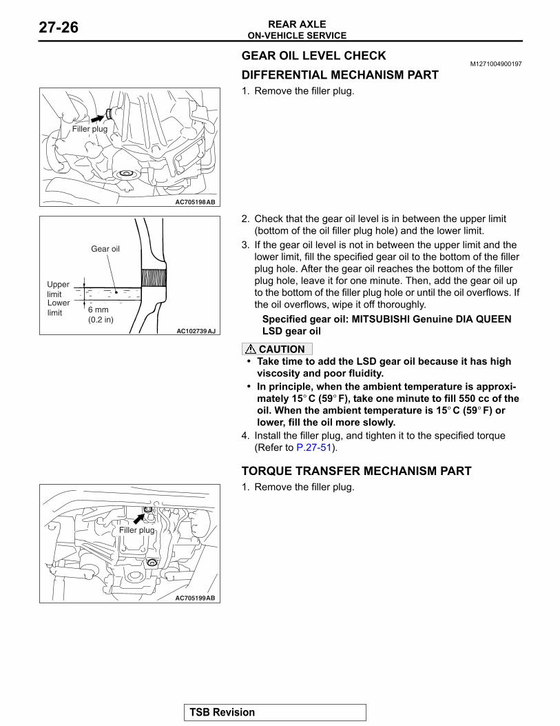
GEAR OIL LEVEL CHECKM1271004900197
DIFFERENTIAL MECHANISM PART1. Remove the filler plug.
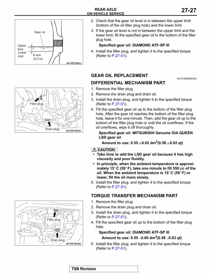
2. Check that the gear oil level is in between the upper limit (bottom of the oil filler plug hole) and the lower limit.
3. If the gear oil level is not in between the upper limit and the lower limit, fill the specified gear oil to the bottom of the filler plug hole. After the gear oil reaches the bottom of the filler plug hole, leave it for one minute. Then, add the gear oil up to the bottom of the filler plug hole or until the oil overflows. If the oil overflows, wipe it off thoroughly.
Specified gear oil: MITSUBISHI Genuine DIA QUEEN LSD gear oil
CAUTION• Take time to add the LSD gear oil because it has high
viscosity and poor fluidity.• In principle, when the ambient temperature is approxi-
mately 15° C (59° F), take one minute to fill 550 cc of the oil. When the ambient temperature is 15° C (59° F) or lower, fill the oil more slowly.
4. Install the filler plug, and tighten it to the specified torque (Refer to P.27-51).
TORQUE TRANSFER MECHANISM PART1. Remove the filler plug.
AC705198AB
Filler plug
AC102739
6 mm(0.2 in)
AJ
Upper limitLower limit
Gear oil
AC705199AB
Filler plug
TSB Revision
ON-VEHICLE SERVICEREAR AXLE 27-27
2. Check that the gear oil level is in between the upper limit (bottom of the oil filler plug hole) and the lower limit.
3. If the gear oil level is not in between the upper limit and the lower limit, fill the specified gear oil to the bottom of the filler plug hole.
Specified gear oil: DIAMOND ATF-SP III4. Install the filler plug, and tighten it to the specified torque
(Refer to P.27-51).
GEAR OIL REPLACEMENTM1272004600423
DIFFERENTIAL MECHANISM PART1. Remove the filler plug.2. Remove the drain plug and drain oil.3. Install the drain plug, and tighten it to the specified torque
(Refer to P.27-51).4. Fill the specified gear oil up to the bottom of the filler plug
hole. After the gear oil reaches the bottom of the filler plug hole, leave it for one minute. Then, add the gear oil up to the bottom of the filler plug hole or until the oil overflows. If the oil overflows, wipe it off thoroughly.
Specified gear oil: MITSUBISHI Genuine DIA QUEEN LSD gear oil
Amount to use: 0.55 ± 0.02 dm3(0.58 ± 0.02 qt)
CAUTION• Take time to add the LSD gear oil because it has high
viscosity and poor fluidity.• In principle, when the ambient temperature is approxi-
mately 15° C (59° F), take one minute to fill 550 cc of the oil. When the ambient temperature is 15° C (59° F) or lower, fill the oil more slowly.
5. Install the filler plug, and tighten it to the specified torque (Refer to P.27-51).
TORQUE TRANSFER MECHANISM PART1. Remove the filler plug.2. Remove the drain plug and drain oil.3. Install the drain plug, and tighten it to the specified torque
(Refer to P.27-51).4. Fill the specified gear oil up to the bottom of the filler plug
hole.Specified gear oil: DIAMOND ATF-SP III
Amount to use: 0.55 − 0.60 dm3(0.58 − 0.63 qt)5. Install the filler plug, and tighten it to the specified torque
(Refer to P.27-51).
AC102739
6 mm(0.2 in)
AJ
Upper limitLower limit
Gear oil
AC705198AC
Filler plug
Drain plug
AC705199AC
Filler plug
Drain plug
TSB Revision
ON-VEHICLE SERVICEREAR AXLE27-28
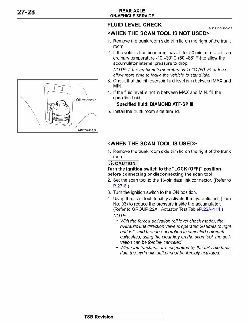
FLUID LEVEL CHECKM1272004700022
<WHEN THE SCAN TOOL IS NOT USED>1. Remove the trunk room side trim lid on the right of the trunk
room.2. If the vehicle has been run, leave it for 90 min. or more in an
ordinary temperature {10 − 30° C (50 − 86° F)} to allow the accumulator internal pressure to drop.NOTE: If the ambient temperature is 10° C (50° F) or less, allow more time to leave the vehicle to stand idle.
3. Check that the oil reservoir fluid level is in between MAX and MIN.
4. If the fluid level is not in between MAX and MIN, fill the specified fluid.
Specified fluid: DIAMOND ATF-SP III5. Install the trunk room side trim lid.
<WHEN THE SCAN TOOL IS USED>1. Remove the trunk room side trim lid on the right of the trunk
room.CAUTION
Turn the ignition switch to the "LOCK (OFF)" position before connecting or disconnecting the scan tool.2. Set the scan tool to the 16-pin data link connector. (Refer to
P.27-6.)3. Turn the ignition switch to the ON position.4. Using the scan tool, forcibly activate the hydraulic unit (item
No. 03) to reduce the pressure inside the accumulator. (Refer to GROUP 22A − Actuator Test TableP.22A-114.)NOTE: .• With the forced activation (oil level check mode), the
hydraulic unit direction valve is operated 20 times to right and left, and then the operation is canceled automati-cally. Also, using the clear key on the scan tool, the acti-vation can be forcibly canceled.
• When the functions are suspended by the fail-safe func-tion, the hydraulic unit cannot be forcibly activated.
AC705200AB
Oil reservoir
TSB Revision
ON-VEHICLE SERVICEREAR AXLE 27-29
5. Check that the oil reservoir fluid level is in between MAX and MIN.
6. If the fluid level is not in between MAX and MIN, fill the specified fluid.
Specified fluid: DIAMOND ATF-SP III7. Install the trunk room side trim lid.
AYC BLEEDINGM1272004800029
CAUTIONAt low temperature the fluid viscosity is so high that air bleeding becomes degenerated. Air bleeding should be done at normal temperatures {10 to 30° C (50 to 86° F)}. 1. Lift up the vehicle.
CAUTIONTurn the ignition switch to the "LOCK (OFF)" position before connecting or disconnecting the scan tool.2. Set the scan tool to the 16-pin data link connector. (Refer to
P.27-6.)3. Turn the ignition switch to the "ON" position.4. Set the steering wheel in the straight-ahead position.5. Using the scan tool, forcibly activate the hydraulic unit (item
No. 02). (Refer to GROUP 22A − Actuator Test Table P.22A-114.)NOTE: .• Forced activation (air bleeding mode) is continued for 5
minutes, and then the operation is canceled automati-cally. Also, using the clear key on the scan tool, the forced activation can be canceled.
• When the functions are suspended by the fail-safe func-tion, the hydraulic unit cannot be forcibly activated.
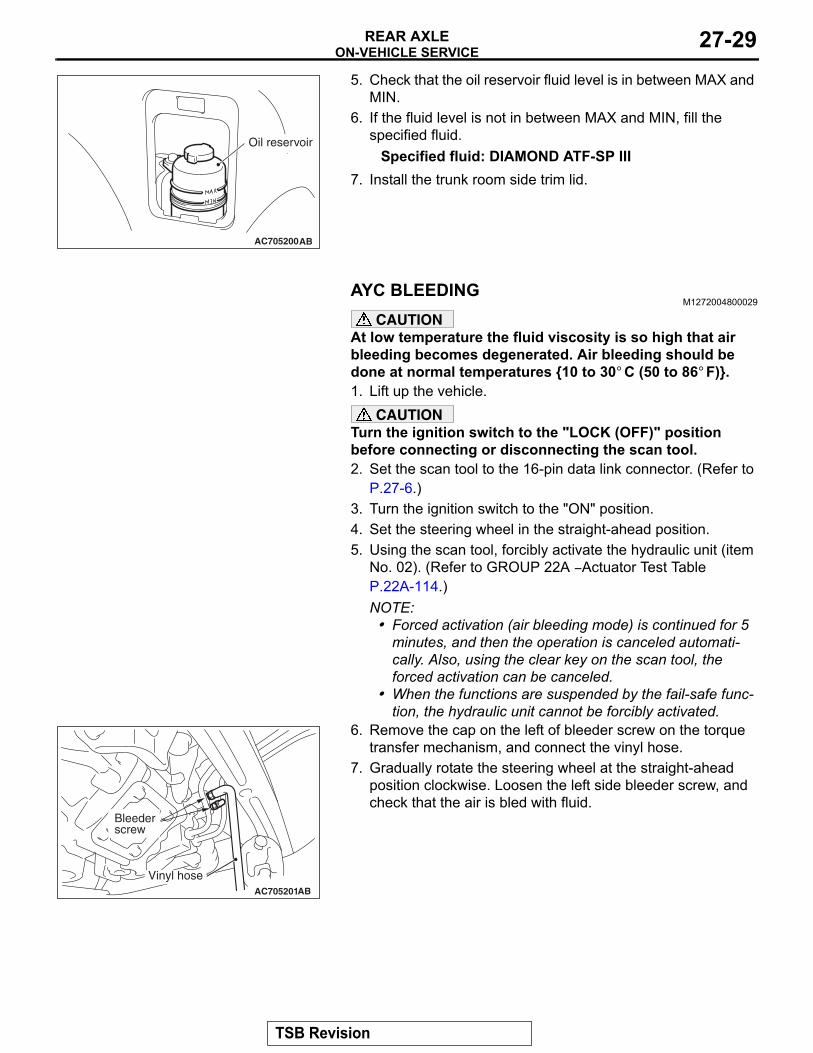
6. Remove the cap on the left of bleeder screw on the torque transfer mechanism, and connect the vinyl hose.
7. Gradually rotate the steering wheel at the straight-ahead position clockwise. Loosen the left side bleeder screw, and check that the air is bled with fluid.
AC705200AB
Oil reservoir
AC705201AB
Vinyl hose
Bleederscrew
TSB Revision
ON-VEHICLE SERVICEREAR AXLE27-30
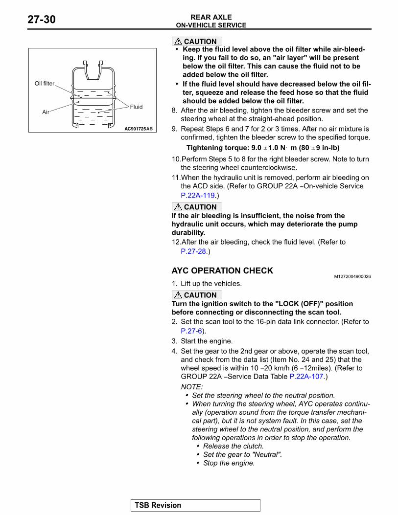
CAUTION• Keep the fluid level above the oil filter while air-bleed-
ing. If you fail to do so, an "air layer" will be present below the oil filter. This can cause the fluid not to be added below the oil filter.
• If the fluid level should have decreased below the oil fil-ter, squeeze and release the feed hose so that the fluid should be added below the oil filter.
8. After the air bleeding, tighten the bleeder screw and set the steering wheel at the straight-ahead position.
9. Repeat Steps 6 and 7 for 2 or 3 times. After no air mixture is confirmed, tighten the bleeder screw to the specified torque.
Tightening torque: 9.0 ± 1.0 N⋅ m (80 ± 9 in-lb)10.Perform Steps 5 to 8 for the right bleeder screw. Note to turn
the steering wheel counterclockwise.11.When the hydraulic unit is removed, perform air bleeding on
the ACD side. (Refer to GROUP 22A − On-vehicle Service P.22A-119.)CAUTION
If the air bleeding is insufficient, the noise from the hydraulic unit occurs, which may deteriorate the pump durability.12.After the air bleeding, check the fluid level. (Refer to
P.27-28.)
AYC OPERATION CHECKM1272004900026
1. Lift up the vehicles.CAUTION
Turn the ignition switch to the "LOCK (OFF)" position before connecting or disconnecting the scan tool.2. Set the scan tool to the 16-pin data link connector. (Refer to
P.27-6).3. Start the engine.4. Set the gear to the 2nd gear or above, operate the scan tool,
and check from the data list (Item No. 24 and 25) that the wheel speed is within 10 − 20 km/h (6 − 12miles). (Refer to GROUP 22A − Service Data Table P.22A-107.)NOTE: .• Set the steering wheel to the neutral position.• When turning the steering wheel, AYC operates continu-
ally (operation sound from the torque transfer mechani-cal part), but it is not system fault. In this case, set the steering wheel to the neutral position, and perform the following operations in order to stop the operation.
• Release the clutch.• Set the gear to "Neutral".• Stop the engine.
AC901725
Oil filter
AirFluid
AB
TSB Revision
ON-VEHICLE SERVICEREAR AXLE 27-31
5. Operate the scan tool to drive the torque transfer mechanism part by the actuator test (item No. 06 and 07) forcibly. (Refer to GROUP 22A − Actuator Test Table P.22A-114.)NOTE: .• Drive the clutch operating mode forcibly for 1 minute,
release the operation automatically. Drive can also be cleared forcibly using the Clear key of the scan tool.
• If the hydraulic unit function has been stopped by fail-safe, the torque transfer differential cannot be forc-ibly driven.
6. Using the scan tool, check that each wheel speed is under the following conditions by the service data (item No. 24 and 25). (Refer to GROUP 22A − Service Data Table P.22A-107.)
<Driving actuator test item No.06 forcibly (Refer to P.22A-114.>The left rear wheel is faster 2 km/h (1 mile/h) than right rear
wheel.<Driving actuator test item No.07 forcibly (Refer to P.22A-114.>The right rear wheel is faster 2 km/h (1 mile/h) than left rear
wheel.NOTE: If the above are not satisfied, check the oil pressure as the system may be faulty.
OIL PRESSURE CHECK M1272005000037
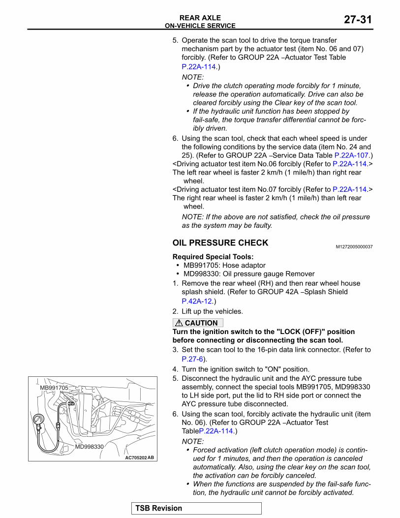
Required Special Tools:• MB991705: Hose adaptor• MD998330: Oil pressure gauge Remover
1. Remove the rear wheel (RH) and then rear wheel house splash shield. (Refer to GROUP 42A − Splash Shield P.42A-12.)
2. Lift up the vehicles.CAUTION
Turn the ignition switch to the "LOCK (OFF)" position before connecting or disconnecting the scan tool.3. Set the scan tool to the 16-pin data link connector. (Refer to
P.27-6).4. Turn the ignition switch to "ON" position.5. Disconnect the hydraulic unit and the AYC pressure tube
assembly, connect the special tools MB991705, MD998330 to LH side port, put the lid to RH side port or connect the AYC pressure tube disconnected.
6. Using the scan tool, forcibly activate the hydraulic unit (item No. 06). (Refer to GROUP 22A − Actuator Test TableP.22A-114.)NOTE: .• Forced activation (left clutch operation mode) is contin-
ued for 1 minutes, and then the operation is canceled automatically. Also, using the clear key on the scan tool, the activation can be forcibly canceled.
• When the functions are suspended by the fail-safe func-tion, the hydraulic unit cannot be forcibly activated.
AC705202AB
MB991705
MD998330
TSB Revision
ON-VEHICLE SERVICEREAR AXLE27-32
CAUTIONWhile the oil pressure is checked, add fluid as necessary to ensure that it is left in the oil reservoir during the entire procedure.7. Check that the generated oil pressure of the hydraulic unit
satisfies the standard value.Standard value: 0.9 − 1.1 MPa (130 − 159 psi)
8. Check the oil pressure of the clutch right side following step 4 through 6. Connect the special tool to RH side port, put the lid to LH side port or connect AYC pressure tube assembly disconnected.
9. Using the scan tool, forcibly activate the hydraulic unit (item No. 07). (Refer to GROUP 22A − Actuator Test TableP.22A-114.)
10.If the measured value exceeds the standard value, replace the hydraulic unit.
11.Connect the hydraulic unit and AYC pressure tube assembly, and tighten them to the specified torque.
Tightening torque: 26 ± 4 N⋅ m (19 ± 3 ft-lb)12.Connect the AYC differential torque transfer mechanism and
AYC pressure tube assembly, and tighten them to the specified torque.
Tightening torque: 21 ± 3 N⋅ m (16 ± 2 ft-lb)13.Perform the AYC air bleeding. (Refer to P.27-29.)
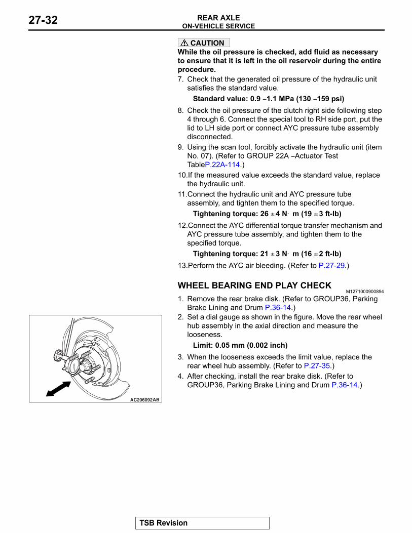
WHEEL BEARING END PLAY CHECKM1271000900894
1. Remove the rear brake disk. (Refer to GROUP36, Parking Brake Lining and Drum P.36-14.)
2. Set a dial gauge as shown in the figure. Move the rear wheel hub assembly in the axial direction and measure the looseness.
Limit: 0.05 mm (0.002 inch)3. When the looseness exceeds the limit value, replace the
rear wheel hub assembly. (Refer to P.27-35.)4. After checking, install the rear brake disk. (Refer to
GROUP36, Parking Brake Lining and Drum P.36-14.)
AC206092AB
TSB Revision
ON-VEHICLE SERVICEREAR AXLE 27-33
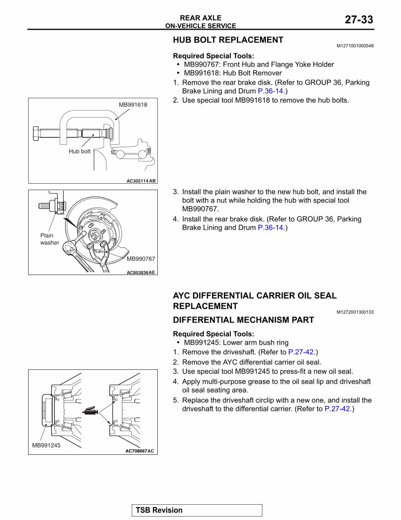
HUB BOLT REPLACEMENTM1271001000548
Required Special Tools:• MB990767: Front Hub and Flange Yoke Holder• MB991618: Hub Bolt Remover
1. Remove the rear brake disk. (Refer to GROUP 36, Parking Brake Lining and Drum P.36-14.)
2. Use special tool MB991618 to remove the hub bolts.
3. Install the plain washer to the new hub bolt, and install the bolt with a nut while holding the hub with special tool MB990767.
4. Install the rear brake disk. (Refer to GROUP 36, Parking Brake Lining and Drum P.36-14.)
AYC DIFFERENTIAL CARRIER OIL SEAL REPLACEMENT
M1272001300133
DIFFERENTIAL MECHANISM PARTRequired Special Tools:• MB991245: Lower arm bush ring
1. Remove the driveshaft. (Refer to P.27-42.)2. Remove the AYC differential carrier oil seal.3. Use special tool MB991245 to press-fit a new oil seal.4. Apply multi-purpose grease to the oil seal lip and driveshaft
oil seal seating area.5. Replace the driveshaft circlip with a new one, and install the
driveshaft to the differential carrier. (Refer to P.27-42.)
AC302114
MB991618
AB
Hub bolt
AC803836
MB990767
AE
Plain washer
AC708667ACMB991245
TSB Revision
ON-VEHICLE SERVICEREAR AXLE27-34
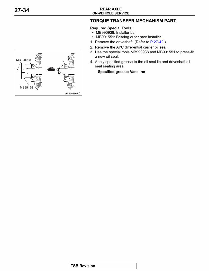
TORQUE TRANSFER MECHANISM PARTRequired Special Tools:• MB990938: Installer bar• MB991551: Bearing outer race installer
1. Remove the driveshaft. (Refer to P.27-42.)2. Remove the AYC differential carrier oil seal.3. Use the special tools MB990938 and MB991551 to press-fit
a new oil seal.4. Apply specified grease to the oil seal lip and driveshaft oil
seal seating area.Specified grease: Vaseline
AC708666AC
MB991551
MB990938
TSB Revision
REAR AXLE HUB ASSEMBLYREAR AXLE 27-35
REAR AXLE HUB ASSEMBLYREMOVAL AND INSTALLATION
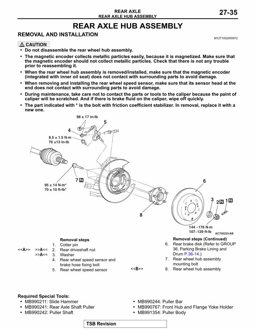
M1271002000972
CAUTION• Do not disassemble the rear wheel hub assembly.• The magnetic encoder collects metallic particles easily, because it is magnetized. Make sure that
the magnetic encoder should not collect metallic particles. Check that there is not any trouble prior to reassembling it.
• When the rear wheel hub assembly is removed/installed, make sure that the magnetic encoder (integrated with inner oil seal) does not contact with surrounding parts to avoid damage.
• When removing and installing the rear wheel speed sensor, make sure that its sensor head at the end does not contact with surrounding parts to avoid damage.
• During maintenance, take care not to contact the parts or tools to the caliper because the paint of caliper will be scratched. And if there is brake fluid on the caliper, wipe off quickly.
• The part indicated with * is the bolt with friction coefficient stabilizer. In removal, replace it with a new one.
Required Special Tools:• MB990211: Slide Hammer• MB990241: Rear Axle Shaft Puller• MB990242: Puller Shaft
• MB990244: Puller Bar• MB990767: Front Hub and Flange Yoke Holder• MB991354: Puller Body
AC705223
23
4
5
6
AB
1 N
8
N
144 176 N·m107 129 ft-lb
95 ± 14 N·m*70 ± 10 ft-lb*
8.5 ± 1.5 N·m76 ±13 in-lb
98 ± 17 in-lb
N
7
Removal steps 1. Cotter pin
<<A>> >>A<< 2. Rear driveshaft nut>>A<< 3. Washer
4. Rear wheel speed sensor and brake hose fixing bolt
5. Rear wheel speed sensor
6. Rear brake disk (Refer to GROUP 36, Parking Brake Lining and Drum P.36-14.)
7. Rear wheel hub assembly mounting bolt
<<B>> 8. Rear wheel hub assembly
Removal steps (Continued)
TSB Revision
REAR AXLE HUB ASSEMBLYREAR AXLE27-36
REMOVAL SERVICE POINTS.
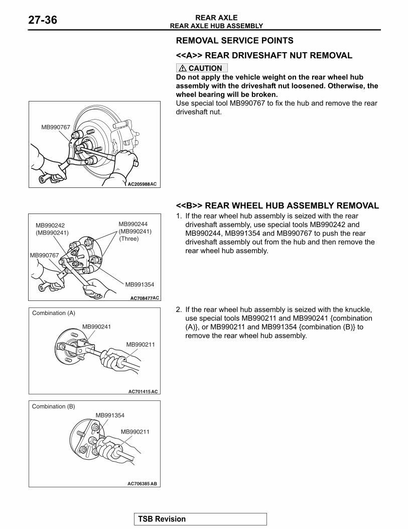
<<A>> REAR DRIVESHAFT NUT REMOVALCAUTION
Do not apply the vehicle weight on the rear wheel hub assembly with the driveshaft nut loosened. Otherwise, the wheel bearing will be broken.Use special tool MB990767 to fix the hub and remove the rear driveshaft nut.
.
<<B>> REAR WHEEL HUB ASSEMBLY REMOVAL1. If the rear wheel hub assembly is seized with the rear
driveshaft assembly, use special tools MB990242 and MB990244, MB991354 and MB990767 to push the rear driveshaft assembly out from the hub and then remove the rear wheel hub assembly.
2. If the rear wheel hub assembly is seized with the knuckle, use special tools MB990211 and MB990241 {combination (A)}, or MB990211 and MB991354 {combination (B)} to remove the rear wheel hub assembly.
AC205988
MB990767
AC
AC708477
MB991354
MB990244(MB990241)
MB990242(MB990241)
AC
MB990767
(Three)
AC701415AC
MB990241
MB990211
Combination (A)
AC706385 AB
MB991354
MB990211
Combination (B)
TSB Revision
REAR AXLE HUB ASSEMBLYREAR AXLE 27-37
INSTALLATION SERVICE POINT.
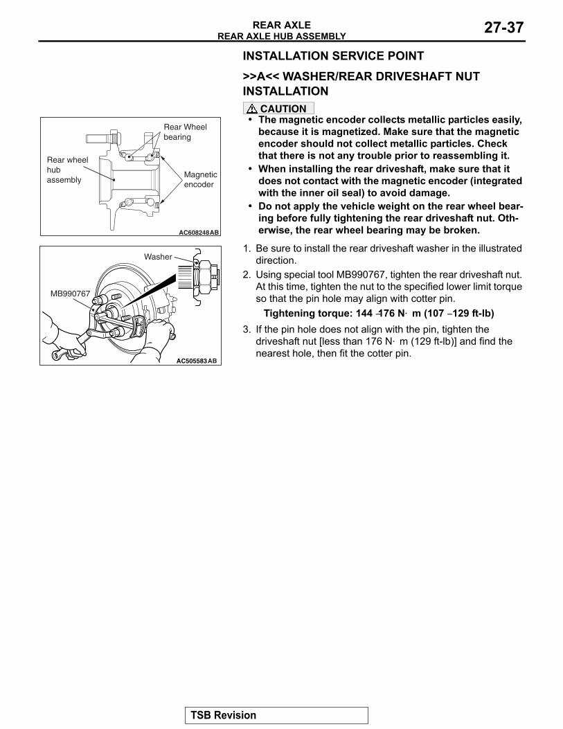
>>A<< WASHER/REAR DRIVESHAFT NUT INSTALLATION
CAUTION• The magnetic encoder collects metallic particles easily,
because it is magnetized. Make sure that the magnetic encoder should not collect metallic particles. Check that there is not any trouble prior to reassembling it.
• When installing the rear driveshaft, make sure that it does not contact with the magnetic encoder (integrated with the inner oil seal) to avoid damage.
• Do not apply the vehicle weight on the rear wheel bear-ing before fully tightening the rear driveshaft nut. Oth-erwise, the rear wheel bearing may be broken.
1. Be sure to install the rear driveshaft washer in the illustrated direction.
2. Using special tool MB990767, tighten the rear driveshaft nut. At this time, tighten the nut to the specified lower limit torque so that the pin hole may align with cotter pin.
Tightening torque: 144 −176 N⋅ m (107 − 129 ft-lb)3. If the pin hole does not align with the pin, tighten the
driveshaft nut [less than 176 N⋅ m (129 ft-lb)] and find the nearest hole, then fit the cotter pin.
AC608248AB
Magneticencoder
Rear Wheelbearing
Rear wheelhubassembly
AC302292
AC505583
MB990767
AB
Washer
TSB Revision
REAR AXLE HUB ASSEMBLYREAR AXLE27-38
INSPECTIONM1271002100407
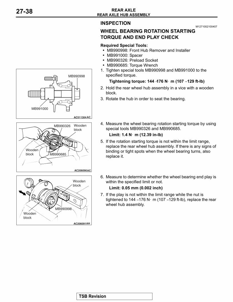
WHEEL BEARING ROTATION STARTING TORQUE AND END PLAY CHECKRequired Special Tools:• MB990998: Front Hub Remover and Installer• MB991000: Spacer• MB990326: Preload Socket• MB990685: Torque Wrench
1. Tighten special tools MB990998 and MB991000 to the specified torque.
Tightening torque: 144 −176 N⋅ m (107 − 129 ft-lb)2. Hold the rear wheel hub assembly in a vice with a wooden
block.3. Rotate the hub in order to seat the bearing.
4. Measure the wheel bearing rotation starting torque by using special tools MB990326 and MB990685.
Limit: 1.4 N⋅ m (12.39 in-lb)5. If the rotation starting torque is not within the limit range,
replace the rear wheel hub assembly. If there is any signs of binding or tight spots when the wheel bearing turns, also replace it.
6. Measure to determine whether the wheel bearing end play is within the specified limit or not.
Limit: 0.05 mm (0.002 inch)7. If the play is not within the limit range while the nut is
tightened to 144 − 176 N⋅ m (107 − 129 ft-lb), replace the rear wheel hub assembly.
AC511304AC
MB991000
MB990998
AC206090AC
MB990326 Woodenblock
MB990685Woodenblock
AC206091AH
MB990998Wooden block
Wooden block
TSB Revision
KNUCKLEREAR AXLE 27-39
KNUCKLEREMOVAL AND INSTALLATION
M1271003000298
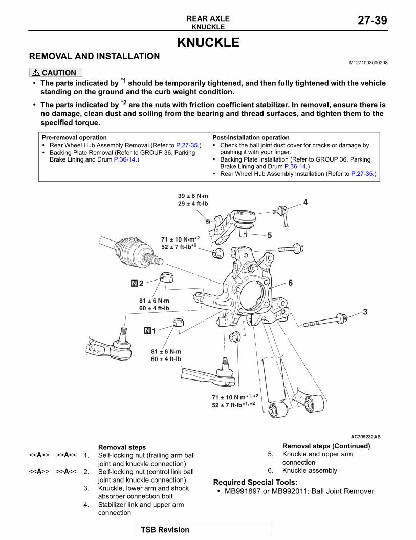
CAUTION• The parts indicated by *1 should be temporarily tightened, and then fully tightened with the vehicle
standing on the ground and the curb weight condition.• The parts indicated by *2 are the nuts with friction coefficient stabilizer. In removal, ensure there is
no damage, clean dust and soiling from the bearing and thread surfaces, and tighten them to the specified torque.
Required Special Tools:• MB991897 or MB992011: Ball Joint Remover
Pre-removal operation• Rear Wheel Hub Assembly Removal (Refer to P.27-35.)• Backing Plate Removal (Refer to GROUP 36, Parking
Brake Lining and Drum P.36-14.)
Post-installation operation• Check the ball joint dust cover for cracks or damage by
pushing it with your finger.• Backing Plate Installation (Refer to GROUP 36, Parking
Brake Lining and Drum P.36-14.)• Rear Wheel Hub Assembly Installation (Refer to P.27-35.)
AC705232
N
2
1
3
N
AB
81 ± 6 N·m60 ± 4 ft-lb
39 ± 6 N·m29 ± 4 ft-lb 4
5
6
71 ± 10 N·m52 ± 7 ft-lb
71 ± 10 N·m52 ± 7 ft-lb
81 ± 6 N·m60 ± 4 ft-lb
2*
2*
2*1,*2*1,*
Removal steps <<A>> >>A<< 1. Self-locking nut (trailing arm ball
joint and knuckle connection)<<A>> >>A<< 2. Self-locking nut (control link ball
joint and knuckle connection)3. Knuckle, lower arm and shock
absorber connection bolt4. Stabilizer link and upper arm
connection
5. Knuckle and upper arm connection
6. Knuckle assembly
Removal steps (Continued)
TSB Revision
KNUCKLEREAR AXLE27-40
REMOVAL SERVICE POINT.
<<A>>SELF-LOCKING NUT REMOVALCAUTION
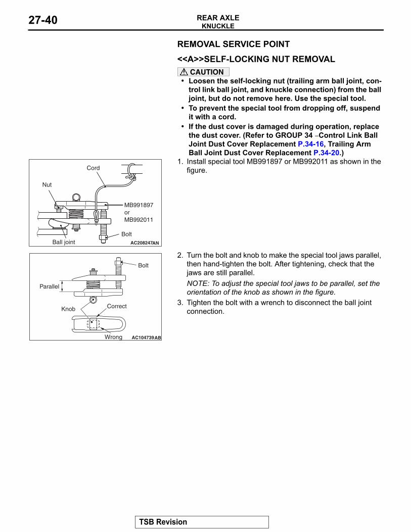
• Loosen the self-locking nut (trailing arm ball joint, con-trol link ball joint, and knuckle connection) from the ball joint, but do not remove here. Use the special tool.
• To prevent the special tool from dropping off, suspend it with a cord.
• If the dust cover is damaged during operation, replace the dust cover. (Refer to GROUP 34 − Control Link Ball Joint Dust Cover Replacement P.34-16, Trailing Arm Ball Joint Dust Cover Replacement P.34-20.)
1. Install special tool MB991897 or MB992011 as shown in the figure.
2. Turn the bolt and knob to make the special tool jaws parallel, then hand-tighten the bolt. After tightening, check that the jaws are still parallel.NOTE: To adjust the special tool jaws to be parallel, set the orientation of the knob as shown in the figure.
3. Tighten the bolt with a wrench to disconnect the ball joint connection.
AC208247AN
Cord
Bolt
MB991897orMB992011
Nut
Ball joint
AC104739AB
Parallel
Knob
Bolt
Correct
Wrong
TSB Revision
KNUCKLEREAR AXLE 27-41
INSTALLATION SERVICE POINT.
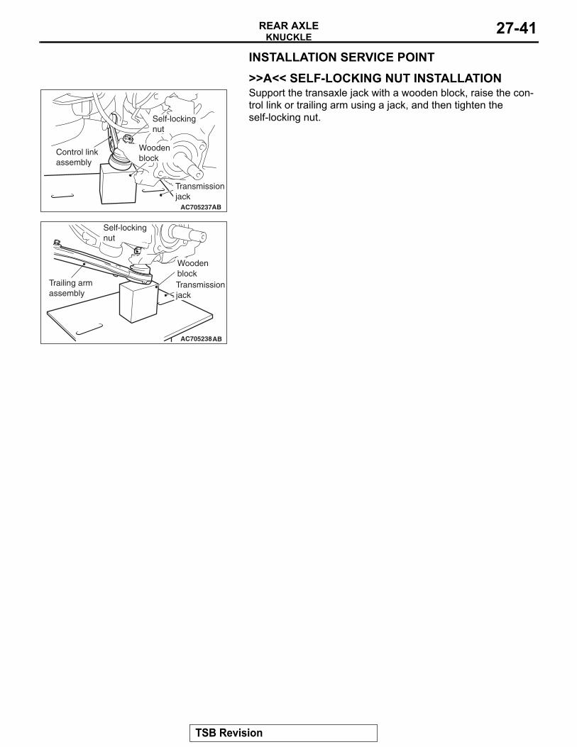
>>A<< SELF-LOCKING NUT INSTALLATIONSupport the transaxle jack with a wooden block, raise the con-trol link or trailing arm using a jack, and then tighten the self-locking nut.
AC705237AB
Transmissionjack
Woodenblock
Self-lockingnut
Control linkassembly
AC705238AB
Self-lockingnut
Trailing armassembly
Transmissionjack
Woodenblock
TSB Revision
DRIVESHAFT ASSEMBLYREAR AXLE27-42
DRIVESHAFT ASSEMBLYREMOVAL AND INSTALLATION
M1271003300460
CAUTION• When removing and installing the rear wheel speed sensor, make sure that the sensor head at the
end does not contact with surrounding parts to avoid damage.• During maintenance, take care not to contact the parts or tools to the caliper because the paint of
caliper will be scratched. And if there is brake fluid on the caliper, wipe off quickly.• The parts indicated by *1 should be temporarily tightened, and then fully tightened with the vehicle
standing on the ground and the curb weight condition.• The part indicated by *2 is the nut with friction coefficient stabilizer. In removal, ensure there is no
damage, clean dust and soiling from the bearing and thread surfaces, and tighten them to the specified torque.
Pre-removal operation• Gear Oil Draining (Refer to P.27-27, P.27-27.)• Center Exhaust Pipe Removal (Refer to GROUP 15,
Exhaust Pipe Removal and Installation P.15-26.)
Post-installation operation• Check the ball joint dust cover for cracks or damage by
pushing it with your finger.• Center Exhaust Pipe Installation (Refer to GROUP 15,
Exhaust Pipe Removal and Installation P.15-26.)• Gear Oil Filling (Refer to P.27-27, P.27-27.)• Wheel Alignment Check and Adjustment (Refer to
GROUP 34, On-vehicle service −Rear Wheel Alignment Check and Adjustment P.34-9 .)
TSB Revision
DRIVESHAFT ASSEMBLYREAR AXLE 27-43
Required Special Tools:• MB990242: Puller Shaft• MB990244: Puller Bar• MB990767: Front Hub and Flange Yoke Holder• MB990998: Front Hub Remover and Installer
• MB991000: Spacer• MB991354: Puller Body• MB991897 or MB992011: Ball Joint Remover
AC705258
N
N 3
1
2
9
7
6
8
10
1213
14
AB
11
7
N
45
8.5 ± 1.5 N·m76 ±13 in-lb
11 ± 2 N·m98 ± 17 in-lb
11 ± 2 N·m98 ± 17 in-lb
11 ± 2 N·m98 ± 17 in-lb
81 ± 6 N·m60 ± 4 ft-lb
71 ± 10 N·m52 ± 7 ft-lb
81 ± 6 N·m60 ± 4 ft-lb
39 ± 6 N·m29 ± 4 ft-lb
144 176 N·m107 129 ft-lb
2*1, *2*1, *
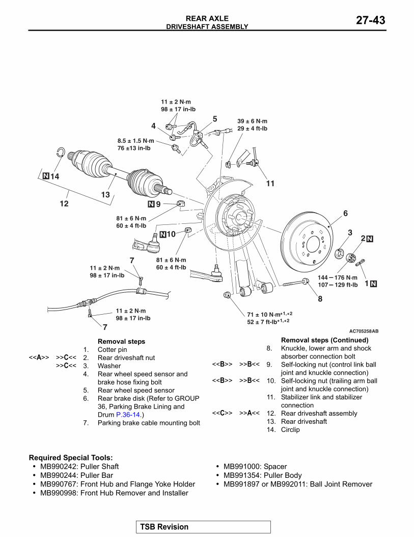
Removal steps 1. Cotter pin
<<A>> >>C<< 2. Rear driveshaft nut>>C<< 3. Washer
4. Rear wheel speed sensor and brake hose fixing bolt
5. Rear wheel speed sensor6. Rear brake disk (Refer to GROUP
36, Parking Brake Lining and Drum P.36-14.)
7. Parking brake cable mounting bolt
8. Knuckle, lower arm and shock absorber connection bolt
<<B>> >>B<< 9. Self-locking nut (control link ball joint and knuckle connection)
<<B>> >>B<< 10. Self-locking nut (trailing arm ball joint and knuckle connection)
11. Stabilizer link and stabilizer connection
<<C>> >>A<< 12. Rear driveshaft assembly13. Rear driveshaft14. Circlip
Removal steps (Continued)
TSB Revision
DRIVESHAFT ASSEMBLYREAR AXLE27-44
REMOVAL SERVICE POINTS.
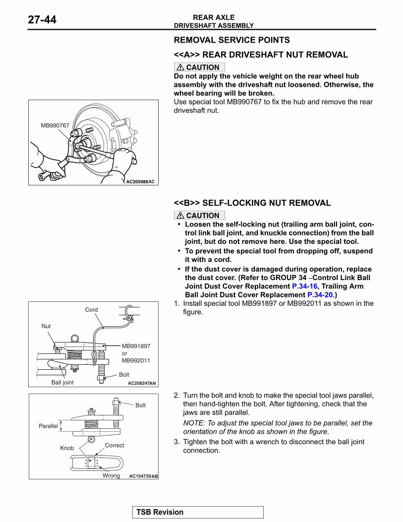
<<A>> REAR DRIVESHAFT NUT REMOVALCAUTION
Do not apply the vehicle weight on the rear wheel hub assembly with the driveshaft nut loosened. Otherwise, the wheel bearing will be broken.Use special tool MB990767 to fix the hub and remove the rear driveshaft nut.
.
<<B>> SELF-LOCKING NUT REMOVALCAUTION
• Loosen the self-locking nut (trailing arm ball joint, con-trol link ball joint, and knuckle connection) from the ball joint, but do not remove here. Use the special tool.
• To prevent the special tool from dropping off, suspend it with a cord.
• If the dust cover is damaged during operation, replace the dust cover. (Refer to GROUP 34 − Control Link Ball Joint Dust Cover Replacement P.34-16, Trailing Arm Ball Joint Dust Cover Replacement P.34-20.)
1. Install special tool MB991897 or MB992011 as shown in the figure.
2. Turn the bolt and knob to make the special tool jaws parallel, then hand-tighten the bolt. After tightening, check that the jaws are still parallel.NOTE: To adjust the special tool jaws to be parallel, set the orientation of the knob as shown in the figure.
3. Tighten the bolt with a wrench to disconnect the ball joint connection.
.
AC205988
MB990767
AC
AC208247AN
Cord
Bolt
MB991897orMB992011
Nut
Ball joint
AC104739AB
Parallel
Knob
Bolt
Correct
Wrong
TSB Revision
DRIVESHAFT ASSEMBLYREAR AXLE 27-45
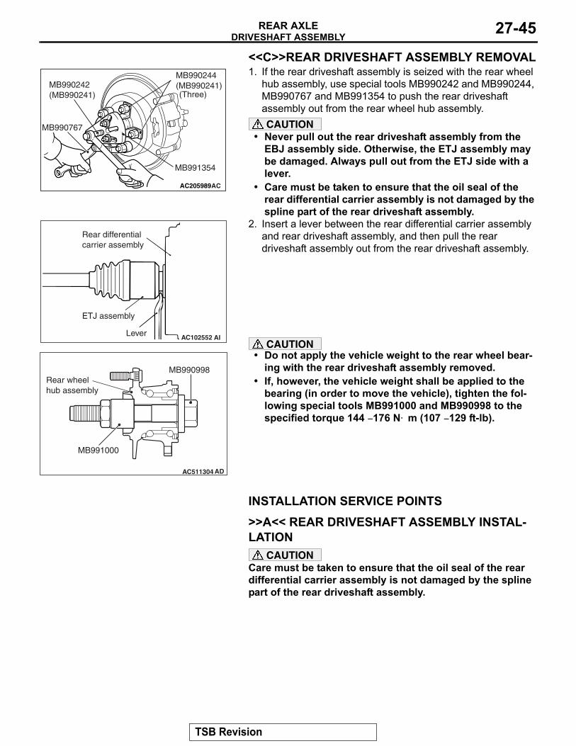
<<C>>REAR DRIVESHAFT ASSEMBLY REMOVAL1. If the rear driveshaft assembly is seized with the rear wheel
hub assembly, use special tools MB990242 and MB990244, MB990767 and MB991354 to push the rear driveshaft assembly out from the rear wheel hub assembly.CAUTION
• Never pull out the rear driveshaft assembly from the EBJ assembly side. Otherwise, the ETJ assembly may be damaged. Always pull out from the ETJ side with a lever.
• Care must be taken to ensure that the oil seal of the rear differential carrier assembly is not damaged by the spline part of the rear driveshaft assembly.
2. Insert a lever between the rear differential carrier assembly and rear driveshaft assembly, and then pull the rear driveshaft assembly out from the rear driveshaft assembly.
CAUTION• Do not apply the vehicle weight to the rear wheel bear-
ing with the rear driveshaft assembly removed.• If, however, the vehicle weight shall be applied to the
bearing (in order to move the vehicle), tighten the fol-lowing special tools MB991000 and MB990998 to the specified torque 144 − 176 N⋅ m (107 − 129 ft-lb).
INSTALLATION SERVICE POINTS.
>>A<< REAR DRIVESHAFT ASSEMBLY INSTAL-LATION
CAUTIONCare must be taken to ensure that the oil seal of the rear differential carrier assembly is not damaged by the spline part of the rear driveshaft assembly..
AC205989
MB991354
MB990244(MB990241)MB990242
(MB990241)
AC
(Three)
MB990767
AC102552 AILever
ETJ assembly
Rear differentialcarrier assembly
AC511304 AD
MB991000
MB990998Rear wheelhub assembly
TSB Revision
DRIVESHAFT ASSEMBLYREAR AXLE27-46
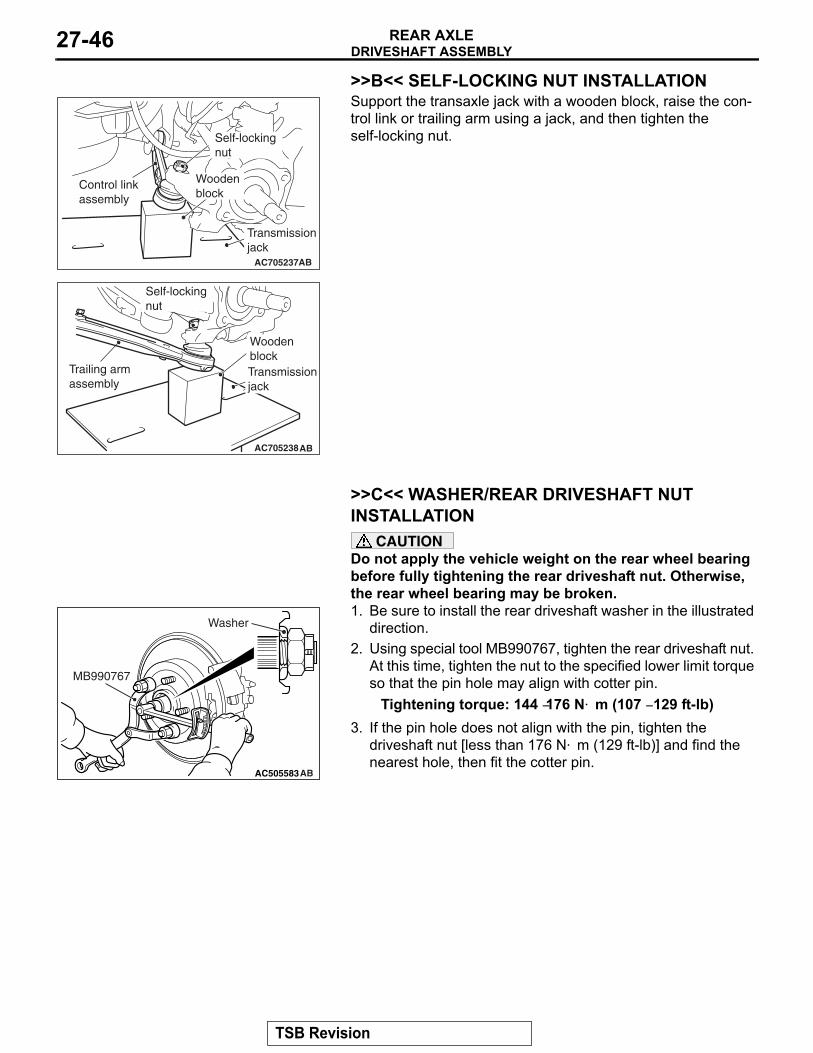
>>B<< SELF-LOCKING NUT INSTALLATIONSupport the transaxle jack with a wooden block, raise the con-trol link or trailing arm using a jack, and then tighten the self-locking nut.
.
>>C<< WASHER/REAR DRIVESHAFT NUT INSTALLATION
CAUTIONDo not apply the vehicle weight on the rear wheel bearing before fully tightening the rear driveshaft nut. Otherwise, the rear wheel bearing may be broken.1. Be sure to install the rear driveshaft washer in the illustrated
direction.2. Using special tool MB990767, tighten the rear driveshaft nut.
At this time, tighten the nut to the specified lower limit torque so that the pin hole may align with cotter pin.
Tightening torque: 144 −176 N⋅ m (107 − 129 ft-lb)3. If the pin hole does not align with the pin, tighten the
driveshaft nut [less than 176 N⋅ m (129 ft-lb)] and find the nearest hole, then fit the cotter pin.
AC705237AB
Transmissionjack
Woodenblock
Self-lockingnut
Control linkassembly
AC705238AB
Self-lockingnut
Trailing armassembly
Transmissionjack
Woodenblock
AC302292
AC505583
MB990767
AB
Washer
TSB Revision
DRIVESHAFT ASSEMBLYREAR AXLE 27-47
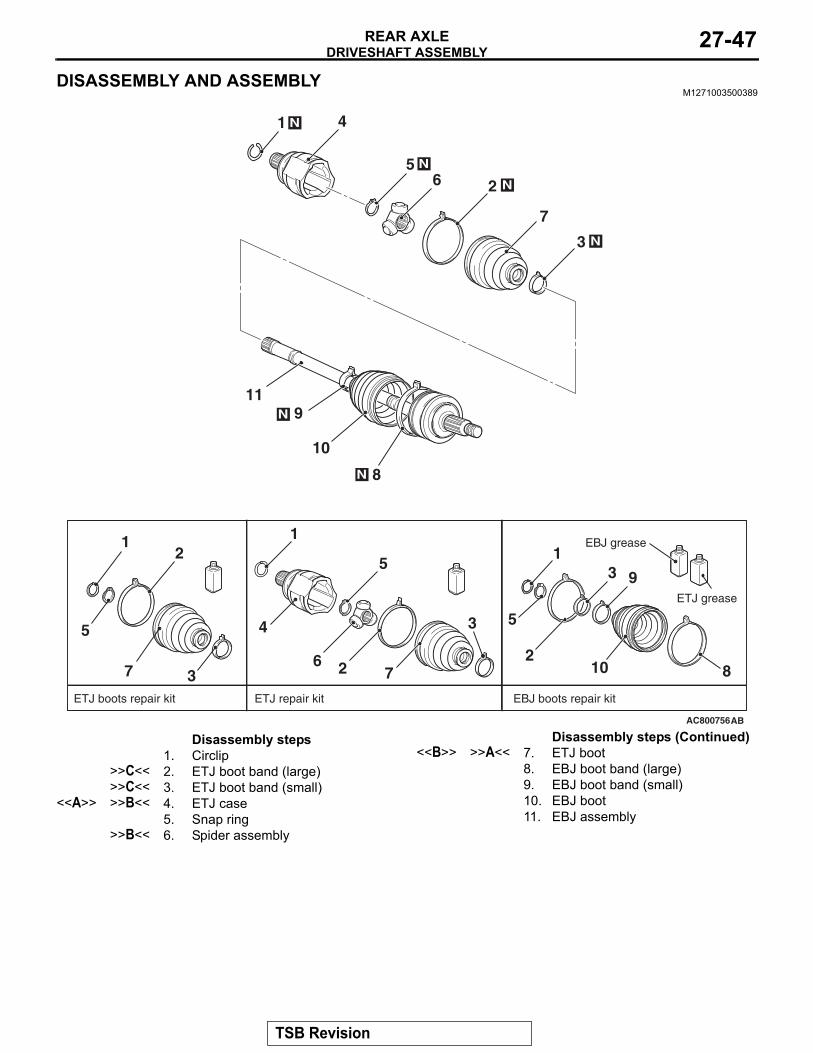
DISASSEMBLY AND ASSEMBLYM1271003500389
AC800756
3
26
7
N
N
10
N
N
11
41 N
9
AB
1
5
2
37
1
4
5
6 2
3
7
1
5
10
3
2
8
8
9
5 N
ETJ boots repair kit ETJ repair kit EBJ boots repair kit
EBJ grease
ETJ grease
Disassembly steps 1. Circlip
>>C<< 2. ETJ boot band (large)>>C<< 3. ETJ boot band (small)
<<A>> >>B<< 4. ETJ case5. Snap ring
>>B<< 6. Spider assembly
<<B>> >>A<< 7. ETJ boot8. EBJ boot band (large)9. EBJ boot band (small)10. EBJ boot11. EBJ assembly
Disassembly steps (Continued)
TSB Revision
DRIVESHAFT ASSEMBLYREAR AXLE27-48
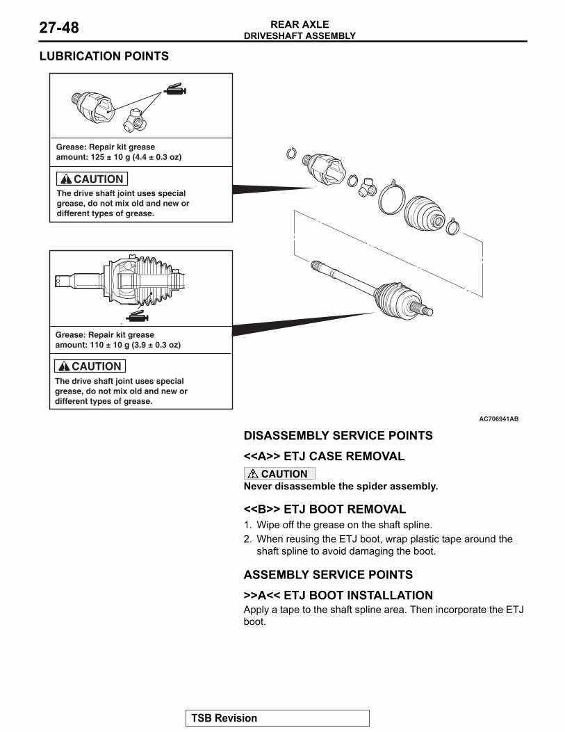
LUBRICATION POINTS
DISASSEMBLY SERVICE POINTS.
<<A>> ETJ CASE REMOVALCAUTION
Never disassemble the spider assembly..
<<B>> ETJ BOOT REMOVAL1. Wipe off the grease on the shaft spline.2. When reusing the ETJ boot, wrap plastic tape around the
shaft spline to avoid damaging the boot.
ASSEMBLY SERVICE POINTS.
>>A<< ETJ BOOT INSTALLATIONApply a tape to the shaft spline area. Then incorporate the ETJ boot..
AC706941AB
The drive shaft joint uses special grease, do not mix old and new or different types of grease.
The drive shaft joint uses special grease, do not mix old and new or different types of grease.
Grease: Repair kit grease amount: 110 ± 10 g (3.9 ± 0.3 oz)
Grease: Repair kit grease amount: 125 ± 10 g (4.4 ± 0.3 oz)
CAUTION
CAUTION
TSB Revision
DRIVESHAFT ASSEMBLYREAR AXLE 27-49
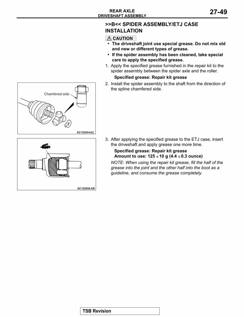
>>B<< SPIDER ASSEMBLY/ETJ CASE INSTALLATION
CAUTION• The driveshaft joint use special grease. Do not mix old
and new or different types of grease.• If the spider assembly has been cleaned, take special
care to apply the specified grease.1. Apply the specified grease furnished in the repair kit to the
spider assembly between the spider axle and the roller.Specified grease: Repair kit grease
2. Install the spider assembly to the shaft from the direction of the spline chamfered side.
3. After applying the specified grease to the ETJ case, insert the driveshaft and apply grease one more time.
Specified grease: Repair kit greaseAmount to use: 125 ± 10 g (4.4 ± 0.3 ounce)
NOTE: When using the repair kit grease, fill the half of the grease into the joint and the other half into the boot as a guideline, and consume the grease completely.
.
AC102654AC
Chamfered side
AC102656 AB
TSB Revision
DRIVESHAFT ASSEMBLYREAR AXLE27-50
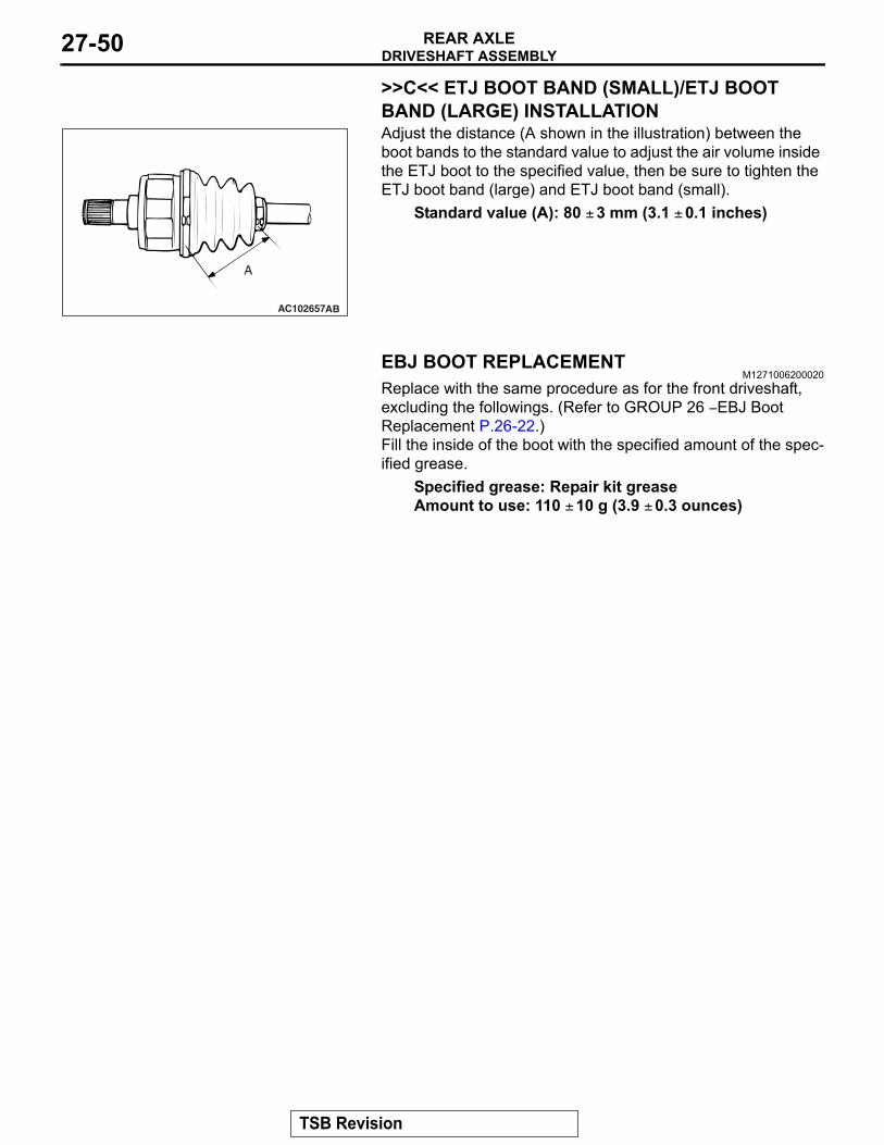
>>C<< ETJ BOOT BAND (SMALL)/ETJ BOOT BAND (LARGE) INSTALLATIONAdjust the distance (A shown in the illustration) between the boot bands to the standard value to adjust the air volume inside the ETJ boot to the specified value, then be sure to tighten the ETJ boot band (large) and ETJ boot band (small).
Standard value (A): 80 ± 3 mm (3.1 ± 0.1 inches)
EBJ BOOT REPLACEMENTM1271006200020
Replace with the same procedure as for the front driveshaft, excluding the followings. (Refer to GROUP 26 − EBJ Boot Replacement P.26-22.) Fill the inside of the boot with the specified amount of the spec-ified grease.
Specified grease: Repair kit greaseAmount to use: 110 ± 10 g (3.9 ± 0.3 ounces)
AC102657AB
A
TSB Revision
DIFFERENTIAL CARRIER ASSEMBLYREAR AXLE 27-51
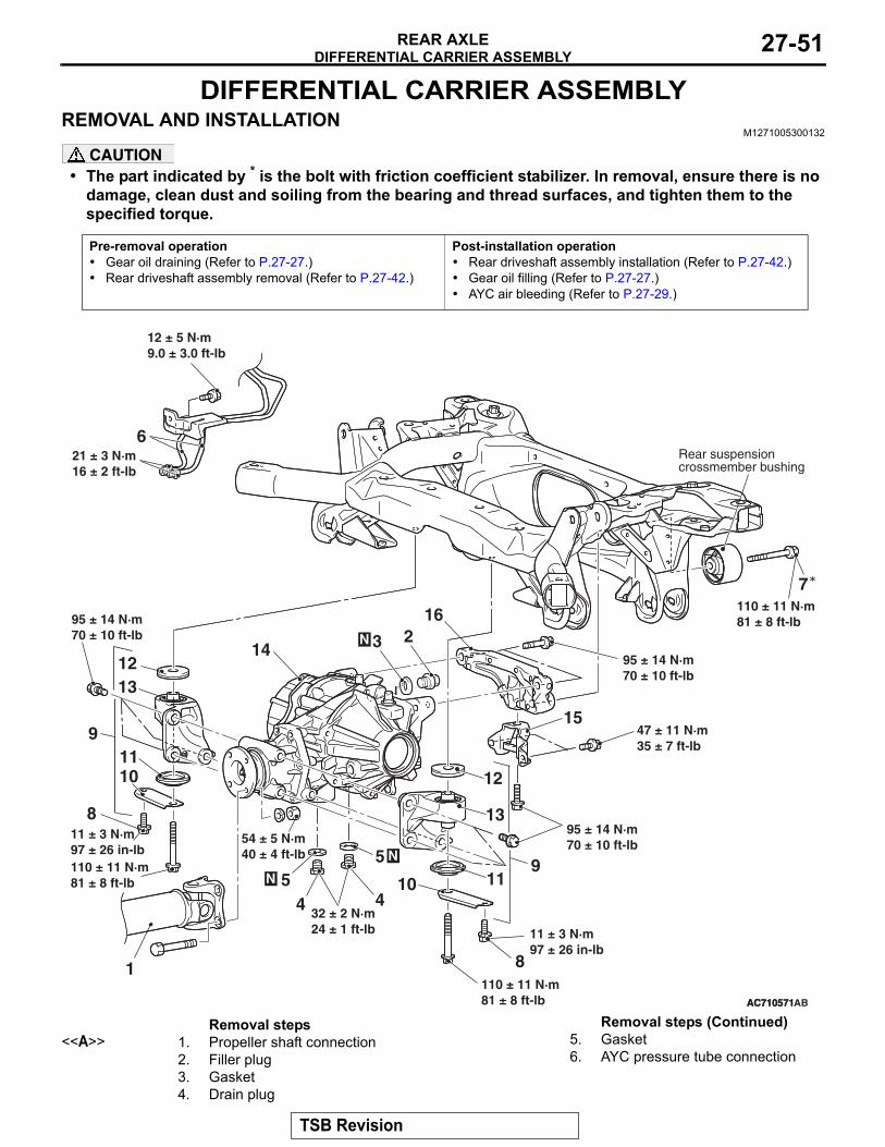
DIFFERENTIAL CARRIER ASSEMBLYREMOVAL AND INSTALLATION
M1271005300132
CAUTION• The part indicated by * is the bolt with friction coefficient stabilizer. In removal, ensure there is no
damage, clean dust and soiling from the bearing and thread surfaces, and tighten them to the specified torque.
Pre-removal operation• Gear oil draining (Refer to P.27-27.)• Rear driveshaft assembly removal (Refer to P.27-42.)
Post-installation operation• Rear driveshaft assembly installation (Refer to P.27-42.)• Gear oil filling (Refer to P.27-27.)• AYC air bleeding (Refer to P.27-29.)
AC710571
Rear suspensioncrossmember bushing
AC710571AB
1
54 ± 5 N·m40 ± 4 ft-lb N
32 ± 2 N·m24 ± 1 ft-lb
21 ± 3 N·m16 ± 2 ft-lb
12 ± 5 N·m9.0 ± 3.0 ft-lb
95 ± 14 N·m70 ± 10 ft-lb
47 ± 11 N·m35 ± 7 ft-lb
95 ± 14 N·m70 ± 10 ft-lb
11 ± 3 N·m97 ± 26 in-lb
N
110 ± 11 N·m81 ± 8 ft-lb
110 ± 11 N·m81 ± 8 ft-lb
110 ± 11 N·m81 ± 8 ft-lb
11 ± 3 N·m97 ± 26 in-lb
95 ± 14 N·m70 ± 10 ft-lb 23
4
5
6
7
8
910
11
1213
14
15
16
45
8
9
10
11
12
13
N
Removal steps <<A>> 1. Propeller shaft connection
2. Filler plug3. Gasket4. Drain plug
5. Gasket6. AYC pressure tube connection
Removal steps (Continued)
TSB Revision
DIFFERENTIAL CARRIER ASSEMBLYREAR AXLE27-52
Required Special Tools:• MB990847: Base• MB991218: Bearing• MB991162: Bolt• MB992234: Bearing• MB992235: Adapter• MB992253: Remover and Installer• MB992254: Base
REMOVAL SERVICE POINT.
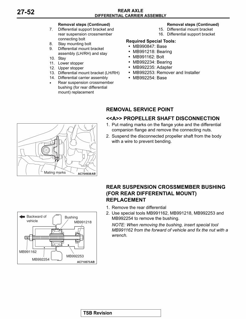
<<A>> PROPELLER SHAFT DISCONNECTION1. Put mating marks on the flange yoke and the differential
companion flange and remove the connecting nuts.2. Suspend the disconnected propeller shaft from the body
with a wire to prevent bending.
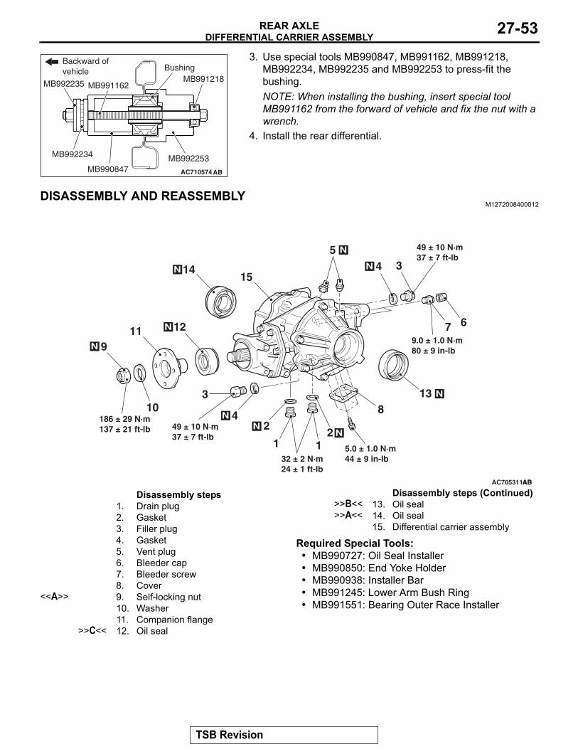
REAR SUSPENSION CROSSMEMBER BUSHING (FOR REAR DIFFERENTIAL MOUNT) REPLACEMENT1. Remove the rear differential2. Use special tools MB991162, MB991218, MB992253 and
MB992254 to remove the bushing.NOTE: When removing the bushing, insert special tool MB991162 from the forward of vehicle and fix the nut with a wrench.
7. Differential support bracket and rear suspension crossmember connecting bolt
8. Stay mounting bolt9. Differential mount bracket
assembly (LH/RH) and stay10. Stay11. Lower stopper12. Upper stopper13. Differential mount bracket (LH/RH)14. Differential carrier assembly• Rear suspension crossmember
bushing (for rear differential mount) replacement
Removal steps (Continued)15. Differential mount bracket16. Differential support bracket
Removal steps (Continued)
AC704938ABMating marks
AC710573ABMB992254
MB992253
MB991218
MB991162
BushingBackward of vehicle
TSB Revision
DIFFERENTIAL CARRIER ASSEMBLYREAR AXLE 27-53
3. Use special tools MB990847, MB991162, MB991218, MB992234, MB992235 and MB992253 to press-fit the bushing.NOTE: When installing the bushing, insert special tool MB991162 from the forward of vehicle and fix the nut with a wrench.
4. Install the rear differential.
DISASSEMBLY AND REASSEMBLYM1272008400012
Required Special Tools:• MB990727: Oil Seal Installer• MB990850: End Yoke Holder• MB990938: Installer Bar • MB991245: Lower Arm Bush Ring• MB991551: Bearing Outer Race Installer
AC710573
AC710574ABMB990847MB992253
MB991218Bushing
Backward of vehicle
MB991162
MB992234
MB992235
AC705311
3
12
9
4
7
5
6
810
11 12
13
14
9.0 ± 1.0 N·m80 ± 9 in-lb
186 ± 29 N·m137 ± 21 ft-lb
32 ± 2 N·m24 ± 1 ft-lb
ABAB
N
N
N
N
N
N
N
2N
15
3
4N
49 ± 10 N·m37 ± 7 ft-lb
1 5.0 ± 1.0 N·m44 ± 9 in-lb
49 ± 10 N·m37 ± 7 ft-lb
Disassembly steps 1. Drain plug2. Gasket3. Filler plug4. Gasket5. Vent plug6. Bleeder cap7. Bleeder screw8. Cover
<<A>> 9. Self-locking nut10. Washer11. Companion flange
>>C<< 12. Oil seal
>>B<< 13. Oil seal>>A<< 14. Oil seal
15. Differential carrier assembly
Disassembly steps (Continued)
TSB Revision
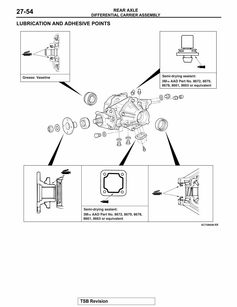
DIFFERENTIAL CARRIER ASSEMBLYREAR AXLE27-54
LUBRICATION AND ADHESIVE POINTS
AC708698 AB
Semi-drying sealant:3MTM AAD Part No. 8672, 8679, 8678, 8661, 8663 or equivalent
Semi-drying sealant:3MTM AAD Part No. 8672, 8679, 8678, 8661, 8663 or equivalent
Grease: Vaseline
TSB Revision
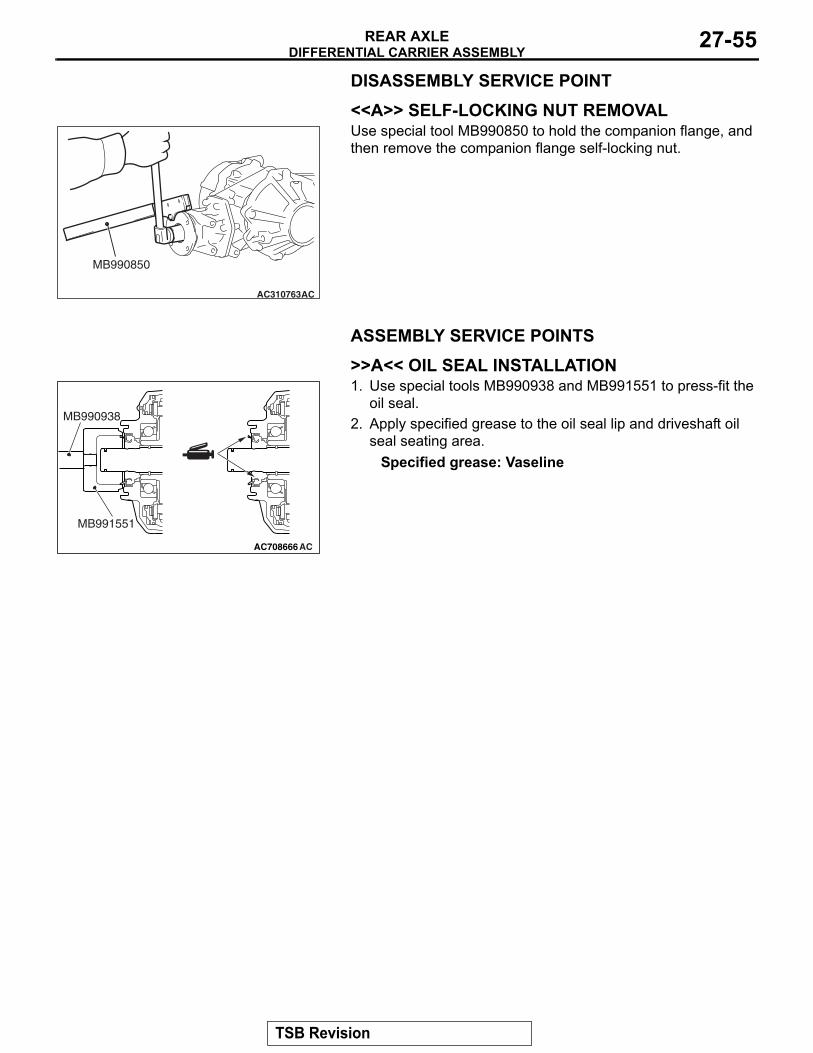
DIFFERENTIAL CARRIER ASSEMBLYREAR AXLE 27-55
DISASSEMBLY SERVICE POINT.
<<A>> SELF-LOCKING NUT REMOVALUse special tool MB990850 to hold the companion flange, and then remove the companion flange self-locking nut.
ASSEMBLY SERVICE POINTS .
>>A<< OIL SEAL INSTALLATION1. Use special tools MB990938 and MB991551 to press-fit the
oil seal.2. Apply specified grease to the oil seal lip and driveshaft oil
seal seating area.Specified grease: Vaseline
.
AC310763AC
MB990850
AC708666AC
MB991551
MB990938
TSB Revision
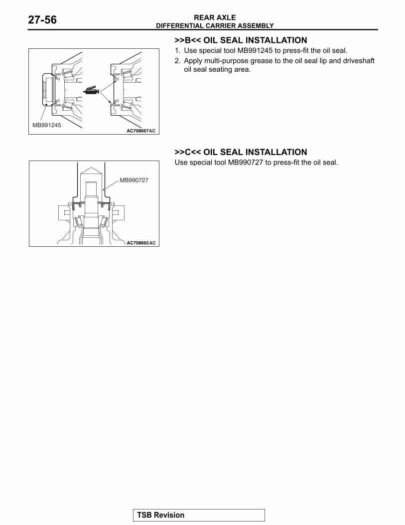
DIFFERENTIAL CARRIER ASSEMBLYREAR AXLE27-56
>>B<< OIL SEAL INSTALLATION1. Use special tool MB991245 to press-fit the oil seal.2. Apply multi-purpose grease to the oil seal lip and driveshaft
oil seal seating area.
.
>>C<< OIL SEAL INSTALLATIONUse special tool MB990727 to press-fit the oil seal.
AC708667ACMB991245
AC708665AC
MB990727
TSB Revision
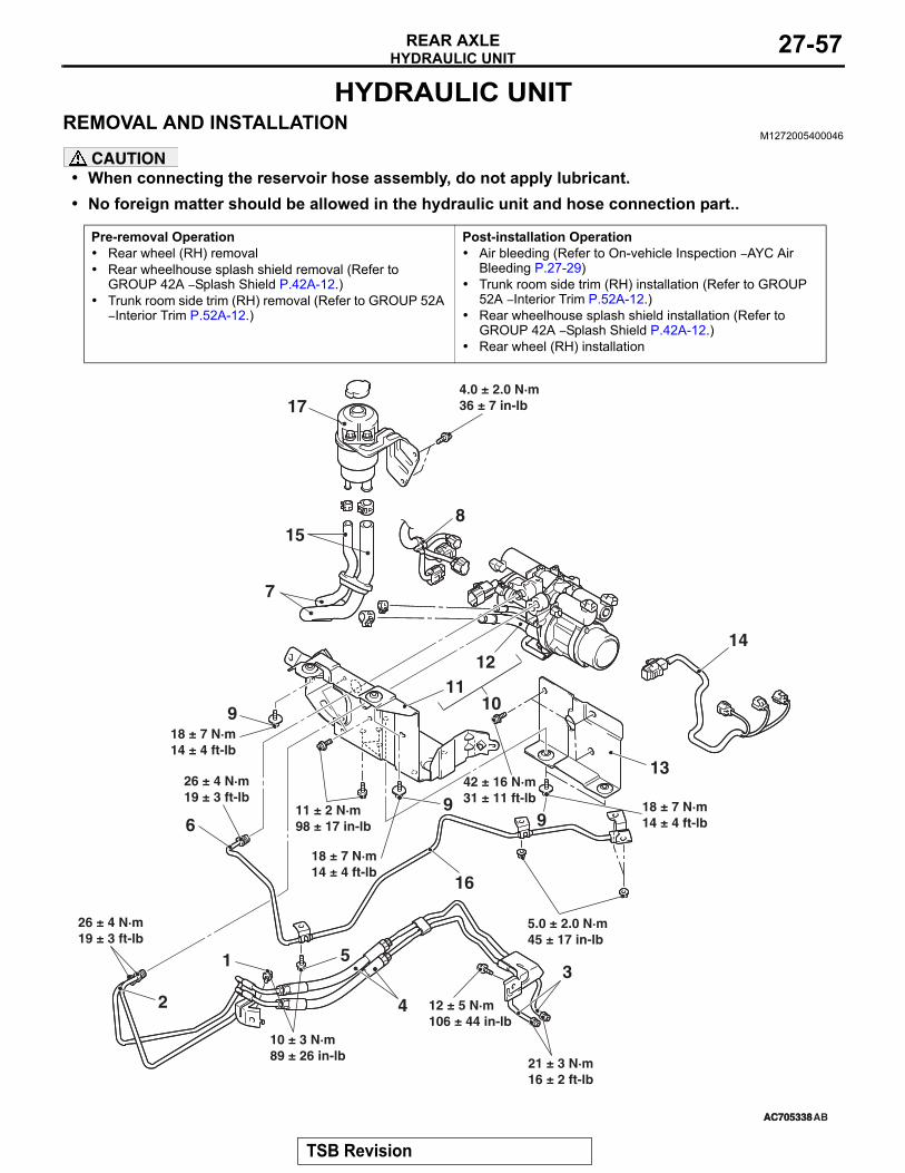
HYDRAULIC UNITREAR AXLE 27-57
HYDRAULIC UNITREMOVAL AND INSTALLATION
M1272005400046
CAUTION• When connecting the reservoir hose assembly, do not apply lubricant.• No foreign matter should be allowed in the hydraulic unit and hose connection part..
Pre-removal Operation• Rear wheel (RH) removal• Rear wheelhouse splash shield removal (Refer to
GROUP 42A − Splash Shield P.42A-12.)• Trunk room side trim (RH) removal (Refer to GROUP 52A
− Interior Trim P.52A-12.)
Post-installation Operation• Air bleeding (Refer to On-vehicle Inspection − AYC Air
Bleeding P.27-29)• Trunk room side trim (RH) installation (Refer to GROUP
52A − Interior Trim P.52A-12.)• Rear wheelhouse splash shield installation (Refer to
GROUP 42A − Splash Shield P.42A-12.)• Rear wheel (RH) installation
AC705338
18 ± 7 N·m14 ± 4 ft-lb
AC705338
31
2
9
4
7
5
6
8
1011
12
4.0 ± 2.0 N·m36 ± 7 in-lb
42 ± 16 N·m31 ± 11 ft-lb
AB
5.0 ± 2.0 N·m45 ± 17 in-lb
9
9
18 ± 7 N·m14 ± 4 ft-lb
11 ± 2 N·m98 ± 17 in-lb
12 ± 5 N·m106 ± 44 in-lb
21 ± 3 N·m16 ± 2 ft-lb
10 ± 3 N·m89 ± 26 in-lb
26 ± 4 N·m19 ± 3 ft-lb
26 ± 4 N·m19 ± 3 ft-lb
18 ± 7 N·m14 ± 4 ft-lb
13
14
16
17
15
TSB Revision
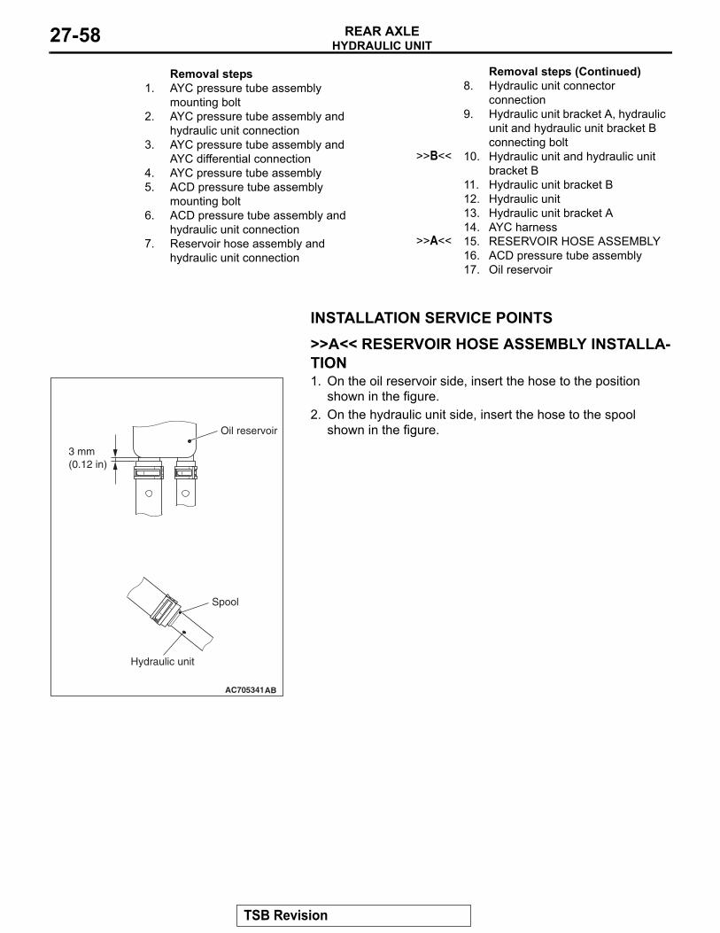
HYDRAULIC UNITREAR AXLE27-58
INSTALLATION SERVICE POINTS.
>>A<< RESERVOIR HOSE ASSEMBLY INSTALLA-TION1. On the oil reservoir side, insert the hose to the position
shown in the figure.2. On the hydraulic unit side, insert the hose to the spool
shown in the figure.
.
Removal steps 1. AYC pressure tube assembly
mounting bolt2. AYC pressure tube assembly and
hydraulic unit connection3. AYC pressure tube assembly and
AYC differential connection4. AYC pressure tube assembly5. ACD pressure tube assembly
mounting bolt6. ACD pressure tube assembly and
hydraulic unit connection7. Reservoir hose assembly and
hydraulic unit connection
8. Hydraulic unit connector connection
9. Hydraulic unit bracket A, hydraulic unit and hydraulic unit bracket B connecting bolt
>>B<< 10. Hydraulic unit and hydraulic unit bracket B
11. Hydraulic unit bracket B12. Hydraulic unit13. Hydraulic unit bracket A14. AYC harness
>>A<< 15. RESERVOIR HOSE ASSEMBLY16. ACD pressure tube assembly17. Oil reservoir
Removal steps (Continued)
AC705341AB
3 mm(0.12 in)
Spool
Hydraulic unit
Oil reservoir
TSB Revision
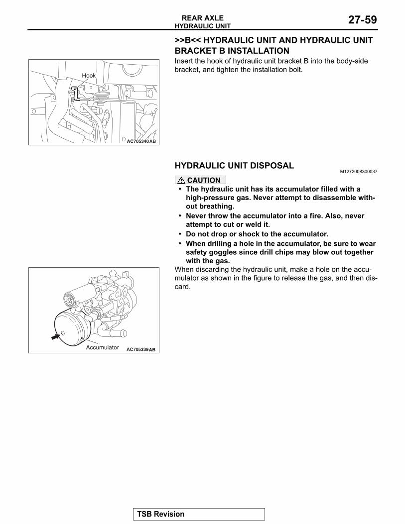
HYDRAULIC UNITREAR AXLE 27-59
>>B<< HYDRAULIC UNIT AND HYDRAULIC UNIT BRACKET B INSTALLATIONInsert the hook of hydraulic unit bracket B into the body-side bracket, and tighten the installation bolt.
HYDRAULIC UNIT DISPOSALM1272008300037
CAUTION• The hydraulic unit has its accumulator filled with a
high-pressure gas. Never attempt to disassemble with-out breathing.
• Never throw the accumulator into a fire. Also, never attempt to cut or weld it.
• Do not drop or shock to the accumulator.• When drilling a hole in the accumulator, be sure to wear
safety goggles since drill chips may blow out together with the gas.
When discarding the hydraulic unit, make a hole on the accu-mulator as shown in the figure to release the gas, and then dis-card.
AC705340AB
Hook
AC705339ABAccumulator
TSB Revision

NOTES