Embed Size (px)
Citation preview
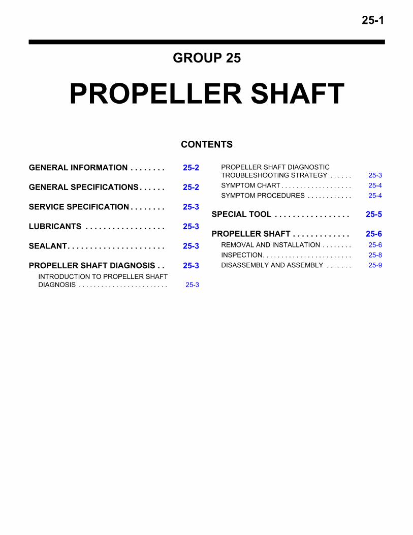
25-1
GROUP 25
PROPELLER SHAFTCONTENTS
GENERAL INFORMATION . . . . . . . . 25-2
GENERAL SPECIFICATIONS. . . . . . 25-2
SERVICE SPECIFICATION . . . . . . . . 25-3
LUBRICANTS . . . . . . . . . . . . . . . . . . 25-3
SEALANT. . . . . . . . . . . . . . . . . . . . . . 25-3
PROPELLER SHAFT DIAGNOSIS . . 25-3INTRODUCTION TO PROPELLER SHAFT DIAGNOSIS . . . . . . . . . . . . . . . . . . . . . . . . 25-3
PROPELLER SHAFT DIAGNOSTIC TROUBLESHOOTING STRATEGY . . . . . . 25-3SYMPTOM CHART . . . . . . . . . . . . . . . . . . . 25-4SYMPTOM PROCEDURES . . . . . . . . . . . . 25-4
SPECIAL TOOL . . . . . . . . . . . . . . . . . 25-5
PROPELLER SHAFT . . . . . . . . . . . . . 25-6REMOVAL AND INSTALLATION . . . . . . . . 25-6INSPECTION. . . . . . . . . . . . . . . . . . . . . . . . 25-8DISASSEMBLY AND ASSEMBLY . . . . . . . 25-9
GENERAL INFORMATIONPROPELLER SHAFT25-2
GENERAL INFORMATIONM1251000100465
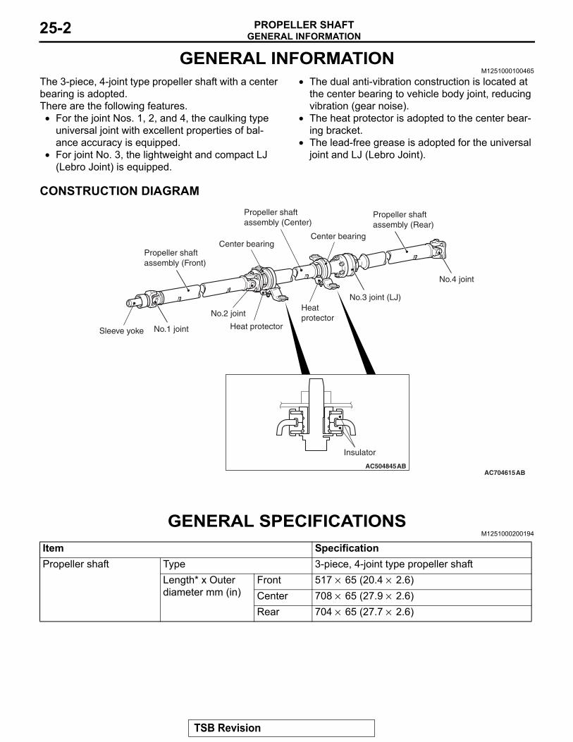
The 3-piece, 4-joint type propeller shaft with a center bearing is adopted.There are the following features.• For the joint Nos. 1, 2, and 4, the caulking type
universal joint with excellent properties of bal-ance accuracy is equipped.
• For joint No. 3, the lightweight and compact LJ (Lebro Joint) is equipped.
• The dual anti-vibration construction is located at the center bearing to vehicle body joint, reducing vibration (gear noise).
• The heat protector is adopted to the center bear-ing bracket.
• The lead-free grease is adopted for the universal joint and LJ (Lebro Joint).
CONSTRUCTION DIAGRAM
AC704615ABAC504845AB
Insulator
Propeller shaftassembly (Front)
Propeller shaftassembly (Center)
Propeller shaftassembly (Rear)
Heat protector
Heat protectorSleeve yoke No.1 joint
No.2 joint
No.3 joint (LJ)
Center bearing
No.4 joint
Center bearing
GENERAL SPECIFICATIONSM1251000200194
Item SpecificationPropeller shaft Type 3-piece, 4-joint type propeller shaft
Length* x Outer diameter mm (in)
Front 517 × 65 (20.4 × 2.6)Center 708 × 65 (27.9 × 2.6)Rear 704 × 65 (27.7 × 2.6)
TSB Revision
SERVICE SPECIFICATIONPROPELLER SHAFT 25-3
NOTE: *: Indicates the distance between each joint center.
SERVICE SPECIFICATIONM1251000300373
Item LimitPropeller shaft runout mm (in) 0.5 (0.02)
LUBRICANTSM1251000400507
Item Specified lubricant QuantityFront propeller shaft sleeve yoke Hypoid gear oil API classification GL-5
SAE90as required
LJ assembly Repair kit grease 75 ± 5 g (2.6 ± 0.1 oz)
SEALANTM1251000500151
Item Specified sealant QuantityLJ assembly rubber packing 3M™ AAD Part No. 8730, 8731 or equivalent As required
PROPELLER SHAFT DIAGNOSISINTRODUCTION TO PROPELLER SHAFT DIAGNOSIS
M1251001800111If an abnormal noise is heard from the propeller shaft while driving, some parts of the propeller shaft may be worn or damaged, or some mounting bolts may be loose.
PROPELLER SHAFT DIAGNOSTIC TROUBLESHOOTING STRATEGYM1251001900129
Use these steps to plan your diagnostic strategy. If you follow them carefully, you will be sure that you have exhausted all of the possible ways to find a pro-peller shaft fault.1. Gather information from the customer.
2. Verify that the condition described by the customer exists.
3. Find the malfunction by following the Symptom Chart.
4. Verify malfunction is eliminated.
Universal joint Type No.1 Cross type (caulking method)No.2 Cross type (caulking method)No.3 Constant velocity type (LJ)No.4 Cross type (caulking method)
Bearing Needle roller bearing (maintenance-free type)Journal diameter mm (in) 18.0 (0.71)
Item Specification
TSB Revision
PROPELLER SHAFT DIAGNOSISPROPELLER SHAFT25-4
SYMPTOM CHARTM1251002000107
Symptom Inspection procedure Reference pageNoise at start 1 P.25-4Noise and vibration at high speed 2 P.25-4
SYMPTOM PROCEDURES
INSPECTION PROCEDURE 1: Noise at Start
DIAGNOSIS
STEP 1. Check if the propeller shaft flange yoke and rear differential connecting nuts and the center bearing mounting nuts are loose.Propeller shaft flange yoke and rear differential con-necting nuts tightening torque: 54 ± 5 N⋅ m (40 ± 4 ft-lb)Center bearing mounting nuts tightening torque: 41 ± 5 N⋅ m (30 ± 3 ft-lb)
Q: Are the connecting nuts and mounting nuts tightened to the specified torque?YES : Go to Step 2.NO : Tighten the connecting nuts and mounting
nuts to the specified torque. Then go to Step 3.
STEP 2. Check the sleeve yoke's spline of front propeller shaft for wear.Q: Is wear apparent?
YES : Replace the propeller shaft. Then go to Step 3.
NO : Go to Step 3.
STEP 3. Retest the system.Q: Is the abnormal noise eliminated?
YES : The procedure is complete.NO : Recheck from Step 1.
INSPECTION PROCEDURE 2: Noise and Vibration at High Speed
DIAGNOSIS
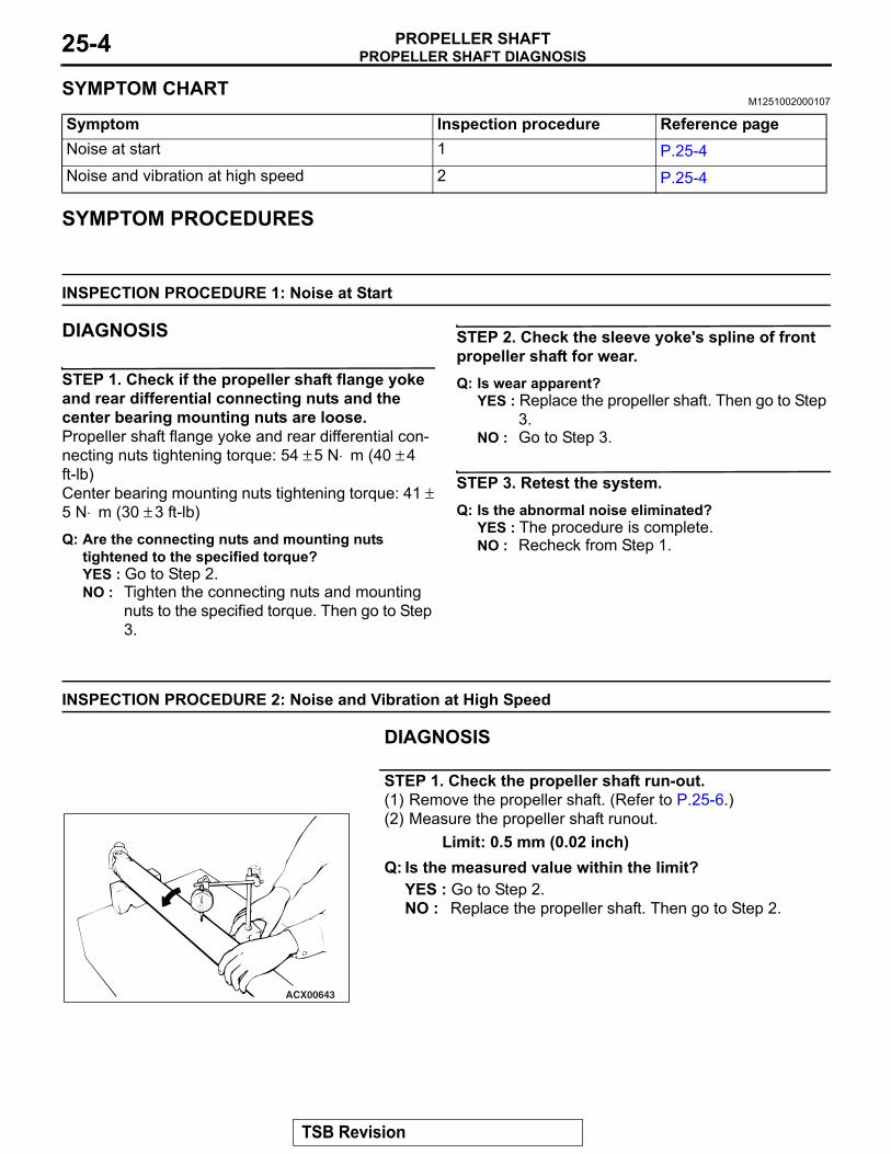
STEP 1. Check the propeller shaft run-out.(1) Remove the propeller shaft. (Refer to P.25-6.)
ACX00643
(2) Measure the propeller shaft runout.Limit: 0.5 mm (0.02 inch)
Q: Is the measured value within the limit?YES : Go to Step 2. NO : Replace the propeller shaft. Then go to Step 2.
TSB Revision
SPECIAL TOOLPROPELLER SHAFT 25-5
STEP 2. Retest the system.Q: Is the abnormal noise eliminated?
YES : The procedure is complete.NO : Recheck from Step1.
SPECIAL TOOLM1251000600352
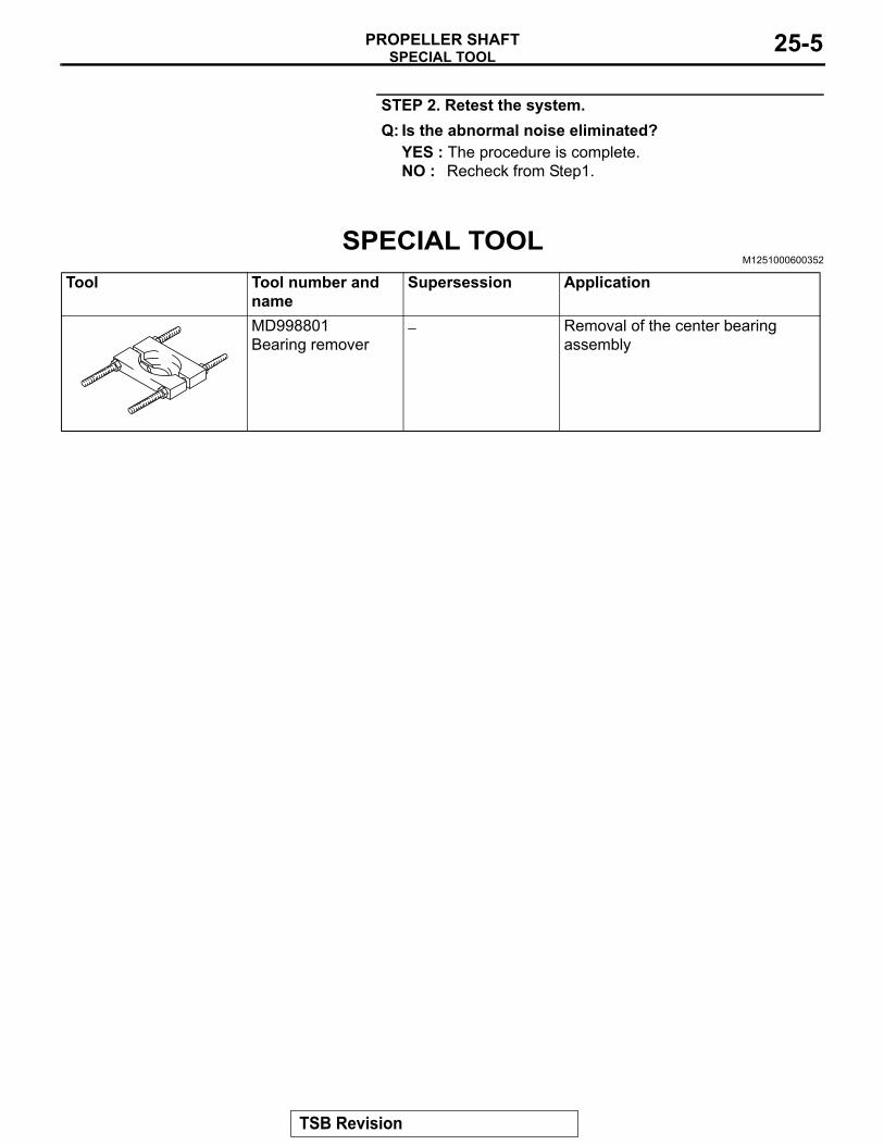
Tool Tool number and name
Supersession Application
MD998801Bearing remover
− Removal of the center bearing assembly
TSB Revision
PROPELLER SHAFTPROPELLER SHAFT25-6
PROPELLER SHAFTREMOVAL AND INSTALLATION
M1251001000698
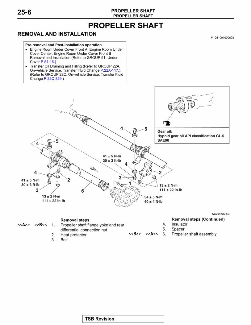
Pre-removal and Post-installation operation• Engine Room Under Cover Front A, Engine Room Under
Cover Center, Engine Room Under Cover Front B Removal and Installation (Refer to GROUP 51, Under Cover P.51-16.)
• Transfer Oil Draining and Filling (Refer to GROUP 22A, On-vehicle Service, Transfer Fluid Change P.22A-117.), (Refer to GROUP 22C, On-vehicle Service, Transfer Fluid Change P.22C-329.)
AC704739
54 ± 5 N·m40 ± 4 ft-lb
41 ± 5 N·m30 ± 3 ft-lb
AB
31
24
5
13 ± 2 N·m111 ± 22 in-lb
32
4
6
4
4
5
41 ± 5 N·m30 ± 3 ft-lb
Gear oil:Hypoid gear oil API classification GL-5SAE90
13 ± 2 N·m111 ± 22 in-lb
Removal steps <<A>> >>B<< 1. Propeller shaft flange yoke and rear
differential connection nut2. Heat protector3. Bolt
4. Insulator5. Spacer
<<B>> >>A<< 6. Propeller shaft assembly
Removal steps (Continued)
TSB Revision
PROPELLER SHAFTPROPELLER SHAFT 25-7
REMOVAL SERVICE POINTS.
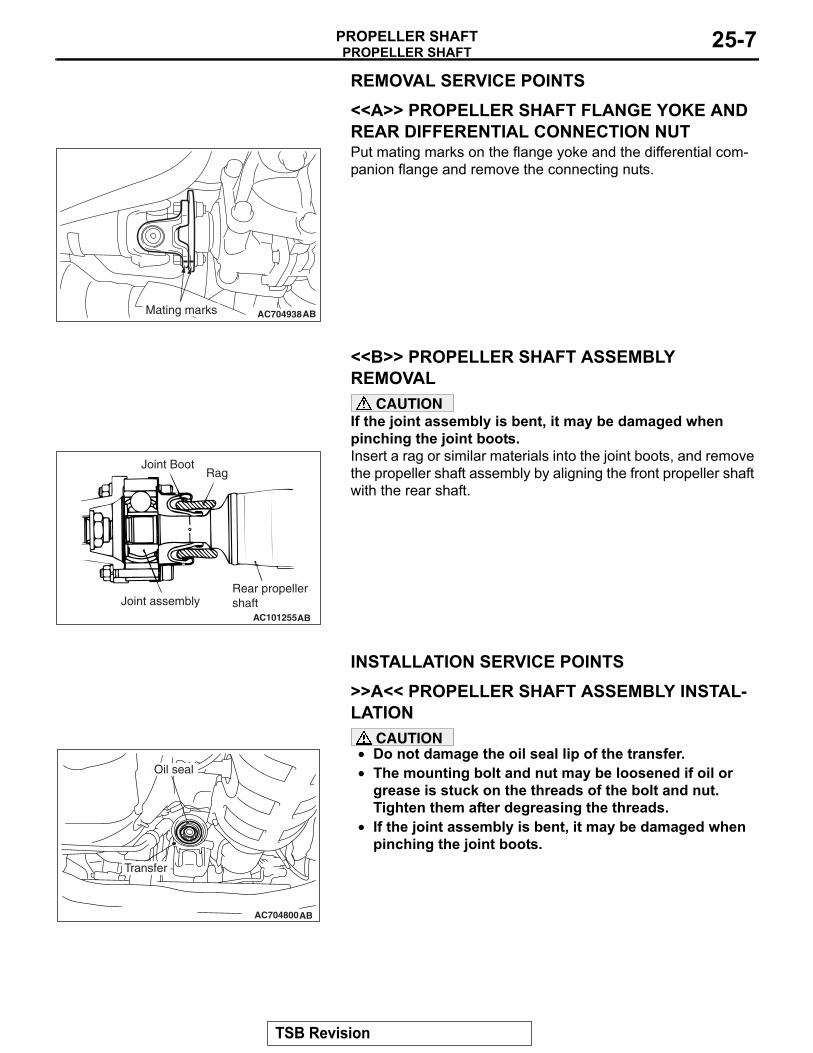
<<A>> PROPELLER SHAFT FLANGE YOKE AND REAR DIFFERENTIAL CONNECTION NUT
AC704938ABMating marks
Put mating marks on the flange yoke and the differential com-panion flange and remove the connecting nuts.
.
<<B>> PROPELLER SHAFT ASSEMBLY REMOVAL
CAUTIONIf the joint assembly is bent, it may be damaged when pinching the joint boots.
AC101255AB
Joint Boot
Joint assembly
Rag
Rear propellershaft
Insert a rag or similar materials into the joint boots, and remove the propeller shaft assembly by aligning the front propeller shaft with the rear shaft.
INSTALLATION SERVICE POINTS.
>>A<< PROPELLER SHAFT ASSEMBLY INSTAL-LATION
CAUTION•
AC704800AB
Transfer
Oil sealDo not damage the oil seal lip of the transfer.
• The mounting bolt and nut may be loosened if oil or grease is stuck on the threads of the bolt and nut. Tighten them after degreasing the threads.
• If the joint assembly is bent, it may be damaged when pinching the joint boots.
.
TSB Revision

PROPELLER SHAFTPROPELLER SHAFT25-8
>>B<< PROPELLER SHAFT FLANGE YOKE AND REAR DIFFERENTIAL CONNECTION NUT INSTALLATIONIf the propeller shaft is reused, align the mating marks and install the connecting nuts.
Tightening torque: 54 ± 5 N⋅ m (40 ± 4 ft-lb)
INSPECTIONM1251001100435
.
PROPELLER SHAFT RUNOUT
ACX00643
Check the deflection of the front, center and rear shafts.Limit: 0.5 mm (0.02 inch)
.
PROPELLER SHAFT UNIVERSAL JOINT PLAY CHECK
AC501206
1. Hold the tube of propeller shaft by one hand, and apply force by the other hand to the flange yoke or sleeve yoke in rotative direction, axial direction, and perpendicular direction for checking looseness.
2. If looseness is recognized, replace the propeller shaft with a new one.
TSB Revision
PROPELLER SHAFTPROPELLER SHAFT 25-9
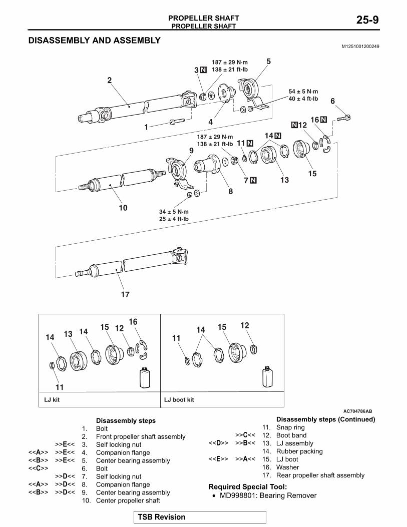
DISASSEMBLY AND ASSEMBLYM1251001200249
AC704786
2
1
N3
4
5
10
9
87 N
11 N14 N
1315
12N16 N
6
17
AB
54 ± 5 N·m40 ± 4 ft-lb
14
11
1612
1315 14
11121514
34 ± 5 N·m25 ± 4 ft-lb
187 ± 29 N·m138 ± 21 ft-lb
187 ± 29 N·m138 ± 21 ft-lb
LJ kit LJ boot kit
Disassembly steps 1. Bolt2. Front propeller shaft assembly
>>E<< 3. Self locking nut<<A>> >>E<< 4. Companion flange<<B>> >>E<< 5. Center bearing assembly<<C>> 6. Bolt
>>D<< 7. Self locking nut<<A>> >>D<< 8. Companion flange<<B>> >>D<< 9. Center bearing assembly
10. Center propeller shaft
11. Snap ring>>C<< 12. Boot band
<<D>> >>B<< 13. LJ assembly14. Rubber packing
<<E>> >>A<< 15. LJ boot16. Washer17. Rear propeller shaft assembly
Required Special Tool:• MD998801: Bearing Remover
Disassembly steps (Continued)
TSB Revision
PROPELLER SHAFTPROPELLER SHAFT25-10
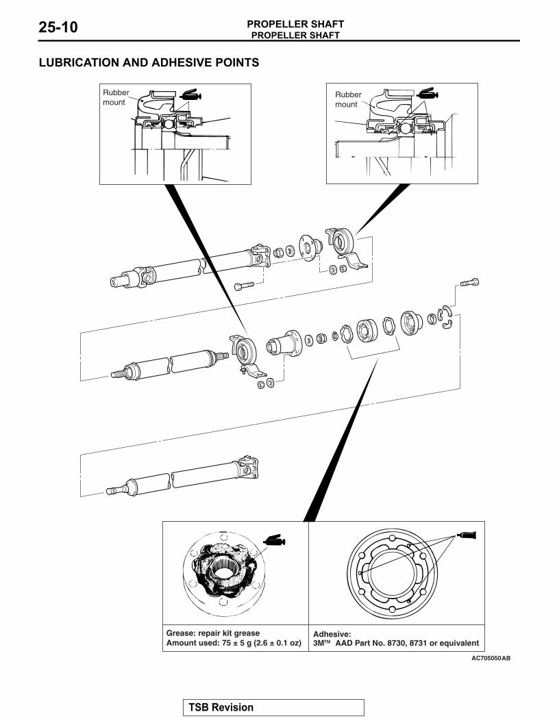
LUBRICATION AND ADHESIVE POINTS
AC705050AB
Rubbermount
Grease: repair kit greaseAmount used: 75 ± 5 g (2.6 ± 0.1 oz)
Rubbermount
TMAdhesive: 3M AAD Part No. 8730, 8731 or equivalent
TSB Revision
PROPELLER SHAFTPROPELLER SHAFT 25-11
DISASSEMBLY SERVICE POINTS.
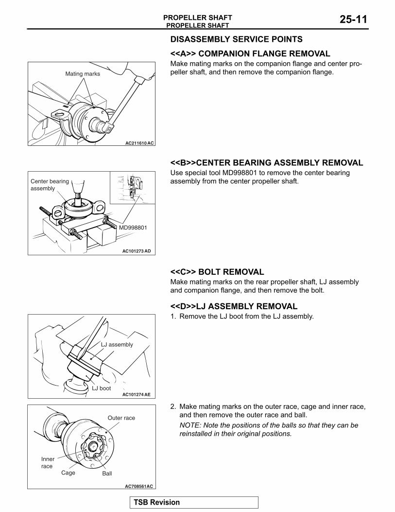
<<A>> COMPANION FLANGE REMOVAL
AC211610 AC
Mating marks
Make mating marks on the companion flange and center pro-peller shaft, and then remove the companion flange.
.
<<B>>CENTER BEARING ASSEMBLY REMOVAL
AC101273
MD998801
AD
Center bearingassembly
Use special tool MD998801 to remove the center bearing assembly from the center propeller shaft.
.
<<C>> BOLT REMOVALMake mating marks on the rear propeller shaft, LJ assembly and companion flange, and then remove the bolt..
<<D>>LJ ASSEMBLY REMOVAL
AC101274
LJ assembly
LJ bootAE
1. Remove the LJ boot from the LJ assembly.
AC708561AC
Outer race
BallCage
Innerrace
2. Make mating marks on the outer race, cage and inner race, and then remove the outer race and ball.NOTE: Note the positions of the balls so that they can be reinstalled in their original positions.
TSB Revision
PROPELLER SHAFTPROPELLER SHAFT25-12
AC101276
Inner race
Puller
Cage
AC
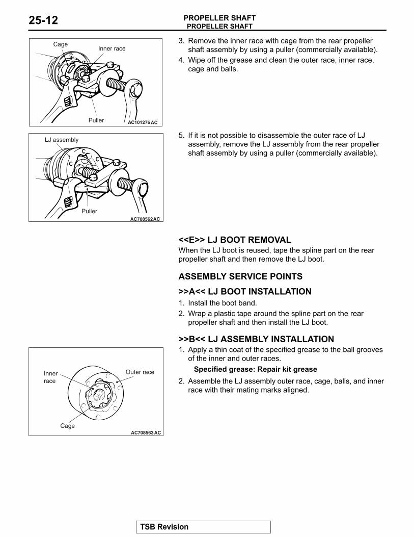
3. Remove the inner race with cage from the rear propeller shaft assembly by using a puller (commercially available).
4. Wipe off the grease and clean the outer race, inner race, cage and balls.
AC708562AC
LJ assembly
Puller
5. If it is not possible to disassemble the outer race of LJ assembly, remove the LJ assembly from the rear propeller shaft assembly by using a puller (commercially available).
.
<<E>> LJ BOOT REMOVALWhen the LJ boot is reused, tape the spline part on the rear propeller shaft and then remove the LJ boot.
ASSEMBLY SERVICE POINTS.
>>A<< LJ BOOT INSTALLATION1. Install the boot band.2. Wrap a plastic tape around the spline part on the rear
propeller shaft and then install the LJ boot..
>>B<< LJ ASSEMBLY INSTALLATION
AC708563AC
Outer race
Cage
Innerrace
1. Apply a thin coat of the specified grease to the ball grooves of the inner and outer races.
Specified grease: Repair kit grease2. Assemble the LJ assembly outer race, cage, balls, and inner
race with their mating marks aligned.
TSB Revision
PROPELLER SHAFTPROPELLER SHAFT 25-13
AC101278AC
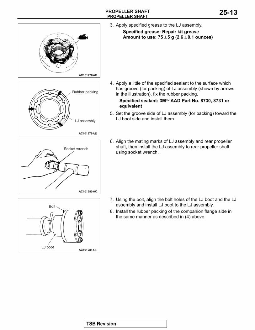
3. Apply specified grease to the LJ assembly.Specified grease: Repair kit greaseAmount to use: 75 ± 5 g (2.6 ± 0.1 ounces)
AC101279AE
Rubber packing
LJ assembly
4. Apply a little of the specified sealant to the surface which has groove (for packing) of LJ assembly (shown by arrows in the illustration), fix the rubber packing.
Specified sealant: 3M™ AAD Part No. 8730, 8731 or equivalent
5. Set the groove side of LJ assembly (for packing) toward the LJ boot side and install them.
AC101280 AC
Socket wrench
6. Align the mating marks of LJ assembly and rear propeller shaft, then install the LJ assembly to rear propeller shaft using socket wrench.
AC101281AE
Bolt
LJ boot
7. Using the bolt, align the bolt holes of the LJ boot and the LJ assembly and install LJ boot to the LJ assembly.
8. Install the rubber packing of the companion flange side in the same manner as described in (4) above.
.
TSB Revision
PROPELLER SHAFTPROPELLER SHAFT25-14
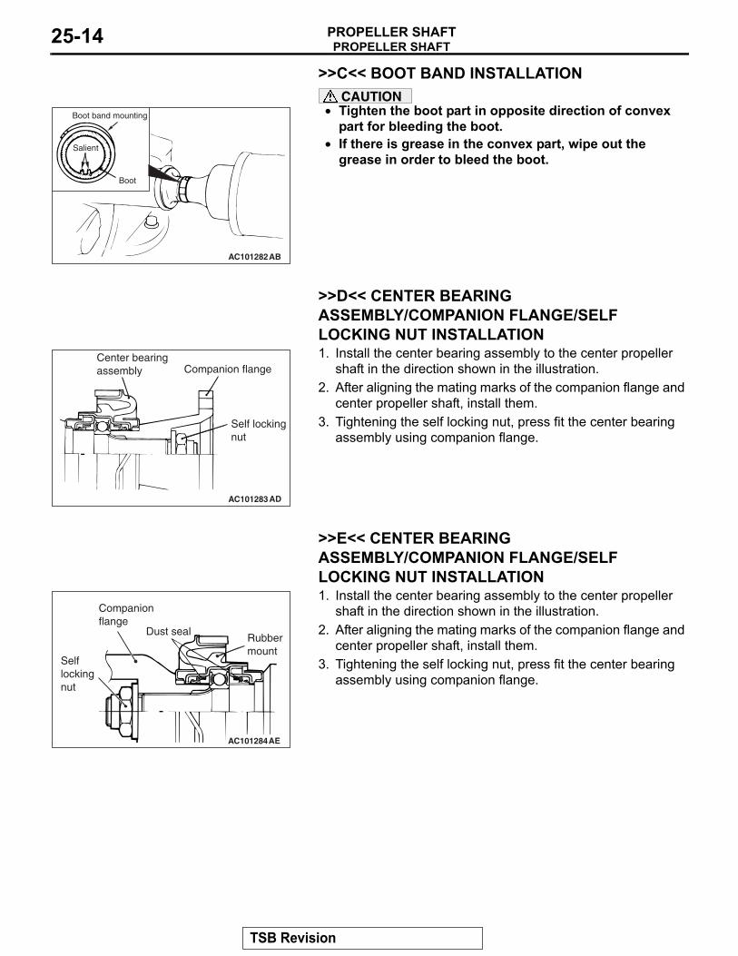
>>C<< BOOT BAND INSTALLATIONCAUTION
•
AC101282AB
Boot
Boot band mounting
Salient
Tighten the boot part in opposite direction of convex part for bleeding the boot.
• If there is grease in the convex part, wipe out the grease in order to bleed the boot.
.
>>D<< CENTER BEARING ASSEMBLY/COMPANION FLANGE/SELF LOCKING NUT INSTALLATION
AC101283AD
Companion flange
Self lockingnut
Center bearingassembly
1. Install the center bearing assembly to the center propeller shaft in the direction shown in the illustration.
2. After aligning the mating marks of the companion flange and center propeller shaft, install them.
3. Tightening the self locking nut, press fit the center bearing assembly using companion flange.
.
>>E<< CENTER BEARING ASSEMBLY/COMPANION FLANGE/SELF LOCKING NUT INSTALLATION
AC101284AE
Rubbermount
Dust seal
Companionflange
Selflockingnut
1. Install the center bearing assembly to the center propeller shaft in the direction shown in the illustration.
2. After aligning the mating marks of the companion flange and center propeller shaft, install them.
3. Tightening the self locking nut, press fit the center bearing assembly using companion flange.
TSB Revision