Embed Size (px)
Citation preview
GROUNDWORK FOR RAIL FLAW DETECTION USINGULTRASONIC PHASED ARRAY INSPECTION
D.Utrata1 and R. Clark2
Center for NDE, Iowa State University, Ames, IA 500112Sperry Rail Service, 46 Shelter Rock Road, Danbury, CT 06810
ABSTRACT. An apparent increase in the detectability of certain flaws results when the ultrasonicinspection beam was oriented off the longitudinal axis of railroad rail. Here, artificial reflectors wereused to better define the extent of material "seen" by inspection beams, and determine how surfacecurvature might affect the inspection. Presumably, such information could be useful for suggestingoptimum positioning of linear array probes in testing, and help determine the validity of simulationmodels of this inspection for various cases.
INTRODUCTION
In previous work, railroad rails having internal transverse defects in the head regionwere scanned via ultrasonic C-scan inspection to reveal the extent of high-amplituderegions that conceivably corresponded to good flaw detection [1-3]. Although such scanswere admittedly not practical for service inspection, it was felt that they could provide anindication of the likelihood of a flaw being detected during the linear sweep of inspectionprobes along the rail. Presumably, the higher this likelihood, the greater would be theprobability of detection for that flaw.
An apparent increase in the detectability of these defects was noted when therefracted 70° angle beam typically used to find such flaws was aligned off of thelongitudinal axis of test rails. This appeared to be the case for standard immersiontransducers, a linear phased array transducer, and a roller search unit (RSU) used in serviceinspection. These results were quite interesting, furthering the suggestion that there couldbe an enhancement possible for rail inspection if non-traditional beam alignments were tobe used.
The questions exist of how much of the rail head is viewed by this alternativeinspection protocol (or any inspection), and how different surface profiles will affect beambehavior. Natural flaws are not suitable for clearly discerning the answers to thesequestions; it's currently not possible to predict the precise signature of an inadequately-defined flaw under varying profiles. However, repeatable calibration reflectors couldconceivably provide such information. In the past, such reflectors have been notoriouslydifficult to produce, or yield signal reflection information confounded by non-relevantphenomena. In this study, a simple new reflector was used on our test rails with seemingsuccess.
Finally, one goal of this ongoing laboratory work, testing rails in immersion, is toprovide benchmark information that will ideally assist in validating ultrasonic simulation
CP657, Review of Quantitative Nondestructive Evaluation Vol. 22, ed. by D. O. Thompson and D. E. Chimenti© 2003 American Institute of Physics 0-7354-0117-9/03/S20.00
799
models. To that end, modeling a simple ultrasonic probe would be easier than modelingthe interface between a fluid-filled wheel's membrane and the rail surface, along with therest of the fluid-filled wheel probe used in service. A series of tests was therefore run toconfirm if the use of a single, undamped transducer from an RSU would see the sameenhanced flaw signatures using "off-axis" alignment. Such tests would also provide someinformation on the nature of signal change from using the fluid-filled wheel membranegoing to fiill immersion.
TEST PROCEDURE
Four rail samples were studied: three worn rail sections with internal defects and anew rail having an as-made profile. Each of these rails had three top-drilled holesmachined into them, at both sides of the rail head, "just in" from the vertical edge of thehead as well as over the center of the web. The holes were 0.25" (6.35 mm) wide and 0.5"(12.7 mm) deep, angled 20° off of the vertical transverse plane. These were thereforesmall, cylindrical holes tilted back to the anticipated configuration of transverse defects,and should provide their strongest reflection when an incident 70° ultrasonic beam wasused for inspection. A photo of a rail sample with a steel rod stuck into one of thesecalibration holes is shone in Figure 1.
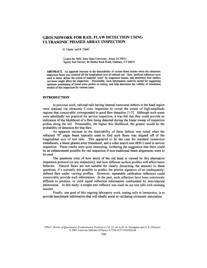
The profiles of the 3 worn rails are shown in Figure 2. As may be seen, thesurfaces of these samples represent varying degrees of head loss and gage face curvature.The unused rail looks symmetric, roughly approximating the field side appearance of Rail1 on both of its sides.
FIGURE 1. A photograph of a test rail with three calibration holes drilled into the top surface. A steel rodis inserted into one of these holes to indicate the angle of the hole, tilted back longitudinally from thetransverse plane. Such reflectors were found to provide clear signals during inspection, avoiding some of thepitfalls associated with other reflectors attempted in calibration rails.
800
FIGURE 2. Profiles of the three worn rails used in this study; gage sides are on the right of the images, withfield sides on the left. Varying degrees of head loss and gage face wear may be seen, going from Rail 1 (left)to Rail 2 (center) to the heavily worn Rail 3 (right). The effect of this varying curvature on flaw detection ispresently unclear.
As with previous work [1-3], automated ultrasonic scans of the test rails were madeusing a Sonix system. Conventional immersion transducers, the transducer from a fluid-filled wheel assembly, the entire fluid-filled wheel, and a linear element phased arraytransducer were scanned along the rail aligned either parallel to the longitudinal axis orrotated toward the field side of the rail.
In all instances, the signal from the top-drilled reflector centered over the web ofthe rail was used to adjust gain on the pulser/receiver. The peak signal from this reflectorwas set to about 100% FSH (full screen height) during a preliminary scan.
RESULTS
A myriad of scans were performed during the course of this work, and a range ofconclusions can be made from them. In the cause of expediency for this document, just afew, select observations will be discussed.
Phased Array Scans of Rails with Machined Reflectors
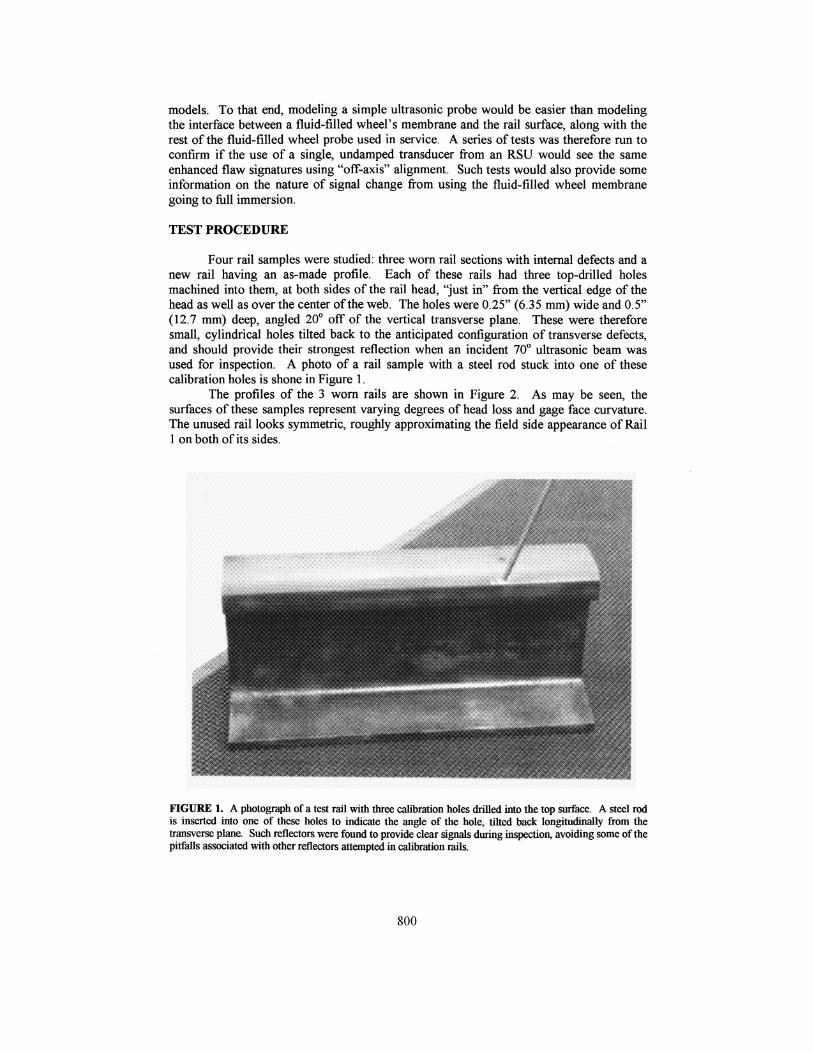
Figure 3 shows the scans of the four test rails, each having the three top-drilled andangled reflectors. The rails were scanned using a 16-element linear array transducer, withno delay laws implemented for steering or focusing. The data was gained by using twotime gates, the first one being 12.5 ji-seconds just subsurface (following the reflection ofthe sample surface) and the second gate representing signals that occurred in the next 22.5[i-seconds of time/depth. This allowed the signals generated from the back sides of theactual holes to be distinguished from the through-metal reflection of the cylindrical sidesof the drilled reflectors. While it is debatable how ultimately useful this scheme was, inthis instance it afforded us the ability to distinguish between internal reflections andsurface waves that were seen to creep into the picture from surface-breaking phenomenonsuch as the drilled holes.
It can be seen that of the three artificial reflectors on these rails, the indications areclearly pronounced and symmetric on the new rail. To varying degrees, their signalsdegrade when curvature of the entry surface is included in the consideration. It is not clearwhy there is not a "perfect symmetry" from the three reflectors in the new rail; it wasexpected that such would be the case. It is evident, however, that when pronouncedcurvature is encountered, such as on the gage face of Rail 3, that the anticipated"rectangular" signature of a drilled hole distorts. Of possibly a greater concern is that theanticipated signature of the reflector, as seen through less dramatic curvature as seen
801
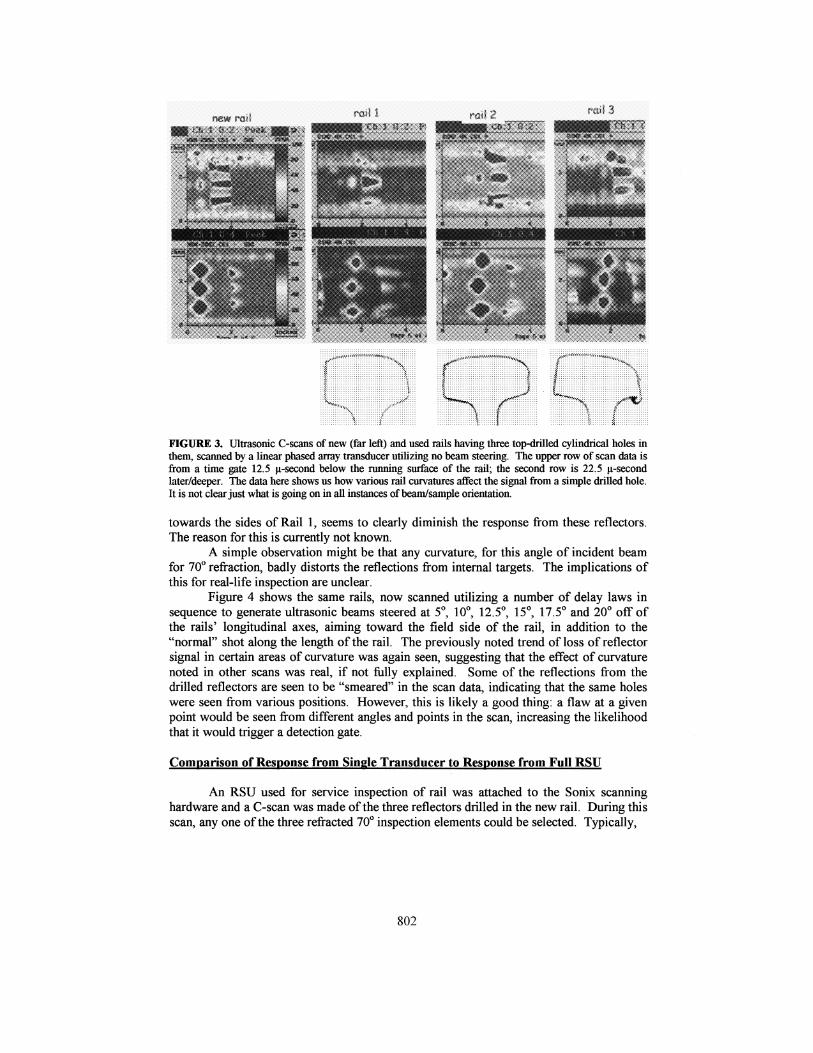
FIGURE 3. Ultrasonic C-scans of new (far left) and used rails having three top-drilled cylindrical holes inthem, scanned by a linear phased array transducer utilizing no beam steering. The upper row of scan data isfrom a time gate 12.5 u-second below the running surface of the rail; the second row is 22.5 u-secondlater/deeper. The data here shows us how various rail curvatures affect the signal from a simple drilled hole.It is not clear just what is going on in all instances of beam/sample orientation.
towards the sides of Rail 1, seems to clearly diminish the response from these reflectors.The reason for this is currently not known.
A simple observation might be that any curvature, for this angle of incident beamfor 70° refraction, badly distorts the reflections from internal targets. The implications ofthis for real-life inspection are unclear.
Figure 4 shows the same rails, now scanned utilizing a number of delay laws insequence to generate ultrasonic beams steered at 5°, 10°, 12.5°, 15°, 17.5° and 20° off ofthe rails' longitudinal axes, aiming toward the field side of the rail, in addition to the"normal" shot along the length of the rail. The previously noted trend of loss of reflectorsignal in certain areas of curvature was again seen, suggesting that the effect of curvaturenoted in other scans was real, if not fully explained. Some of the reflections from thedrilled reflectors are seen to be "smeared" in the scan data, indicating that the same holeswere seen from various positions. However, this is likely a good thing: a flaw at a givenpoint would be seen from different angles and points in the scan, increasing the likelihoodthat it would trigger a detection gate.
Comparison of Response from Single Transducer to Response from Full RSU
An RSU used for service inspection of rail was attached to the Sonix scanninghardware and a C-scan was made of the three reflectors drilled in the new rail. During thisscan, any one of the three refracted 70° inspection elements could be selected. Typically,
802
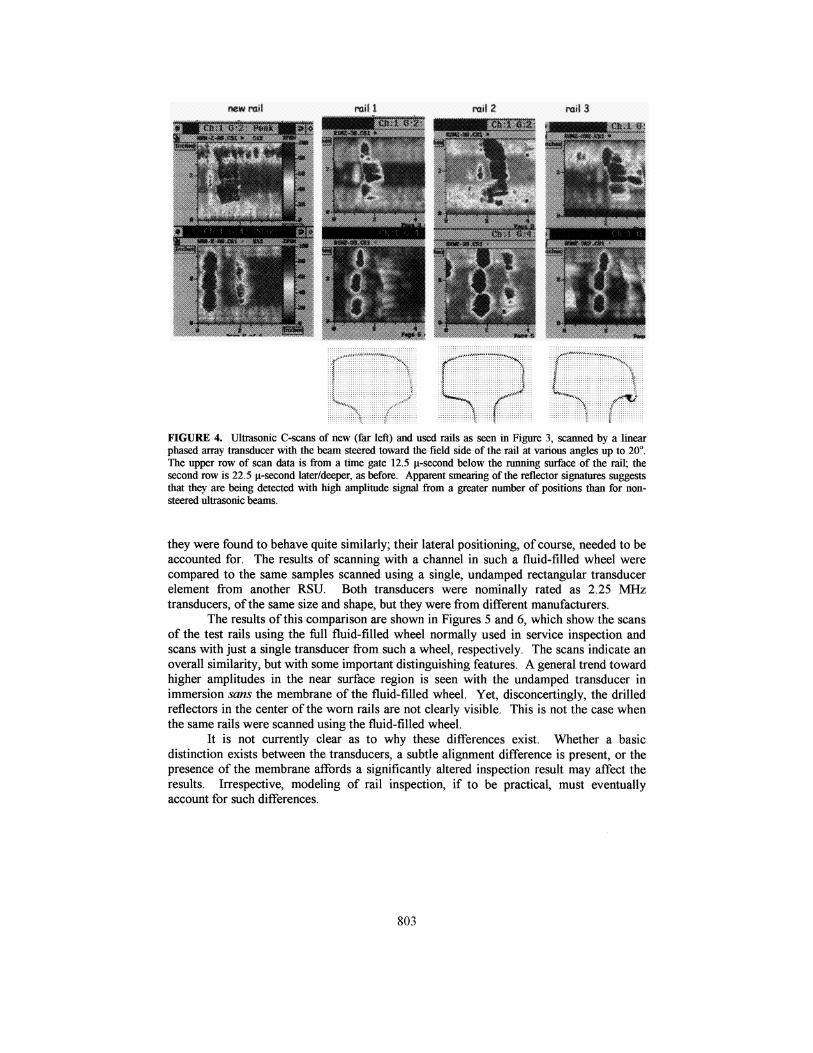
FIGURE 4. Ultrasonic C-scans of new (far left) and used rails as seen in Figure 3, scanned by a linearphased array transducer with the beam steered toward the field side of the rail at various angles up to 20°.The upper row of scan data is from a time gate 12.5 u-second below the running surface of the rail; thesecond row is 22.5 u-second later/deeper, as before. Apparent smearing of the reflector signatures suggeststhat they are being detected with high amplitude signal from a greater number of positions than for non-steered ultrasonic beams.
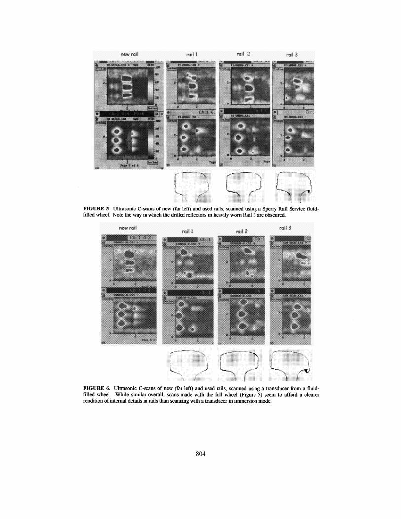
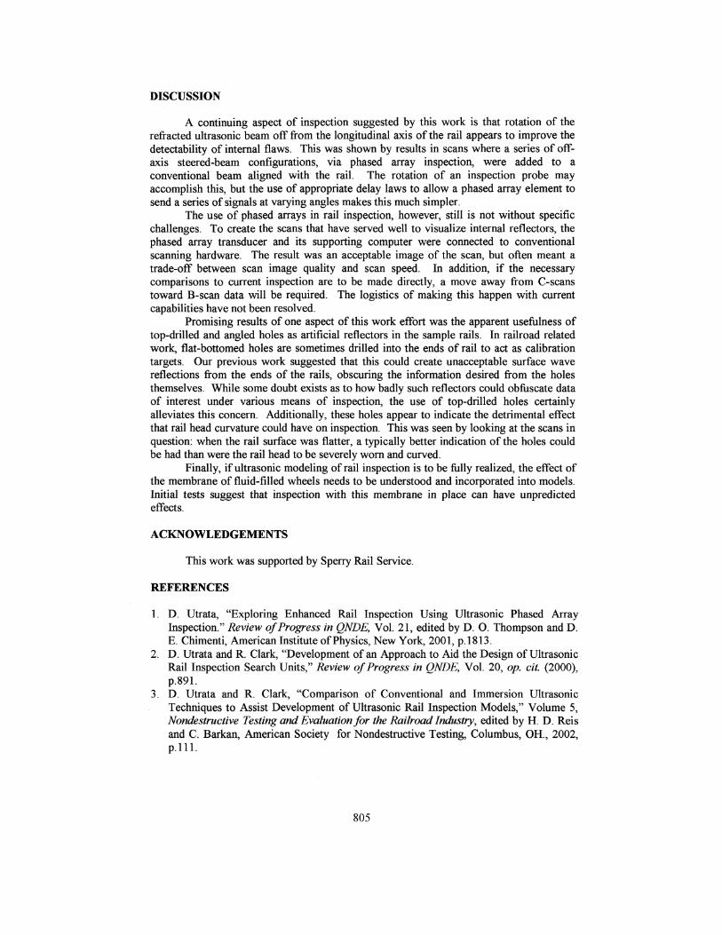
they were found to behave quite similarly; their lateral positioning, of course, needed to beaccounted for. The results of scanning with a channel in such a fluid-filled wheel werecompared to the same samples scanned using a single, undamped rectangular transducerelement from another RSU. Both transducers were nominally rated as 2.25 MHztransducers, of the same size and shape, but they were from different manufacturers.
The results of this comparison are shown in Figures 5 and 6, which show the scansof the test rails using the full fluid-filled wheel normally used in service inspection andscans with just a single transducer from such a wheel, respectively. The scans indicate anoverall similarity, but with some important distinguishing features. A general trend towardhigher amplitudes in the near surface region is seen with the undamped transducer inimmersion sans the membrane of the fluid-filled wheel. Yet, disconcertingly, the drilledreflectors in the center of the worn rails are not clearly visible. This is not the case whenthe same rails were scanned using the fluid-filled wheel.
It is not currently clear as to why these differences exist. Whether a basicdistinction exists between the transducers, a subtle alignment difference is present, or thepresence of the membrane affords a significantly altered inspection result may affect theresults. Irrespective, modeling of rail inspection, if to be practical, must eventuallyaccount for such differences.
803
ft! mi 1 will
FIGURE 5. Ultrasonic C-scans of new (far left) and used rails, scanned using a Sperry Rail Service fluid-filled wheel. Note the way in which the drilled reflectors in heavily worn Rail 3 are obscured.
FIGURE 6. Ultrasonic C-scans of new (far left) and used rails, scanned using a transducer from a fluid-filled wheel. While similar overall, scans made with the full wheel (Figure 5) seem to afford a clearerrendition of internal details in rails than scanning with a transducer in immersion mode.
804
DISCUSSION
A continuing aspect of inspection suggested by this work is that rotation of therefracted ultrasonic beam off from the longitudinal axis of the rail appears to improve thedetectability of internal flaws. This was shown by results in scans where a series of off-axis steered-beam configurations, via phased array inspection, were added to aconventional beam aligned with the rail. The rotation of an inspection probe mayaccomplish this, but the use of appropriate delay laws to allow a phased array element tosend a series of signals at varying angles makes this much simpler.
The use of phased arrays in rail inspection, however, still is not without specificchallenges. To create the scans that have served well to visualize internal reflectors, thephased array transducer and its supporting computer were connected to conventionalscanning hardware. The result was an acceptable image of the scan, but often meant atrade-off between scan image quality and scan speed. In addition, if the necessarycomparisons to current inspection are to be made directly, a move away from C-scanstoward B-scan data will be required. The logistics of making this happen with currentcapabilities have not been resolved.
Promising results of one aspect of this work effort was the apparent usefulness oftop-drilled and angled holes as artificial reflectors in the sample rails. In railroad relatedwork, flat-bottomed holes are sometimes drilled into the ends of rail to act as calibrationtargets. Our previous work suggested that this could create unacceptable surface wavereflections from the ends of the rails, obscuring the information desired from the holesthemselves. While some doubt exists as to how badly such reflectors could obfuscate dataof interest under various means of inspection, the use of top-drilled holes certainlyalleviates this concern. Additionally, these holes appear to indicate the detrimental effectthat rail head curvature could have on inspection. This was seen by looking at the scans inquestion: when the rail surface was flatter, a typically better indication of the holes couldbe had than were the rail head to be severely worn and curved.
Finally, if ultrasonic modeling of rail inspection is to be fully realized, the effect ofthe membrane of fluid-filled wheels needs to be understood and incorporated into models.Initial tests suggest that inspection with this membrane in place can have unpredictedeffects.
ACKNOWLEDGEMENTS
This work was supported by Sperry Rail Service.
REFERENCES
1. D. Utrata, "Exploring Enhanced Rail Inspection Using Ultrasonic Phased ArrayInspection." Review of Progress in QNDE, Vol. 21, edited by D. O. Thompson and D.E. Chimenti, American Institute of Physics, New York, 2001, p. 1813.
2. D. Utrata and R. Clark, "Development of an Approach to Aid the Design of UltrasonicRail Inspection Search Units," Review of Progress in QNDE, Vol. 20, op. cit (2000),p.891.
3. D. Utrata and R. Clark, "Comparison of Conventional and Immersion UltrasonicTechniques to Assist Development of Ultrasonic Rail Inspection Models," Volume 5,Nondestructive Testing and Evaluation for the Railroad Industry\ edited by H. D. Reisand C. Barkan, American Society for Nondestructive Testing, Columbus, OH., 2002,p.lll.
805