Embed Size (px)
Citation preview

Groundwater Model Progress Report 08, Red Hill Bulk Fuel Storage Facility JOINT BASE PEARL HARBOR-HICKAM, O‘AHU, HAWAI‘I Administrative Order on Consent in the Matter of Red Hill Bulk Fuel Storage Facility, EPA Docket Number RCRA 7003-R9-2015-01 and DOH Docket Number 15-UST-EA-01, Attachment A, Statement of Work Section 6.2, Section 7.1.2, Section 7.2.2, and Section 7.3.2
August 5, 2019 Revision 00
Comprehensive Long-Term Environmental Action Navy Contract Number N62742-17-D-1800, CTO18F0126

This page intentionally left blank
Groundwater Model Progress 1
Report 08, Red Hill Bulk Fuel 2
Storage Facility 3
JOINT BASE PEARL HARBOR-HICKAM, O‘AHU, HAWAI‘I 4
Administrative Order on Consent in the Matter of Red Hill Bulk Fuel Storage 5 Facility, EPA Docket Number RCRA 7003-R9-2015-01 and 6 DOH Docket Number 15-UST-EA-01, Attachment A, Statement of Work 7 Section 6.2, Section 7.1.2, Section 7.2.2, and Section 7.3.2 8
August 5, 2019 9 Revision 00 10
Prepared for: 11
Defense Logistics Agency Energy 12 8725 John J Kingman Rd Suite 4950 13 Fort Belvoir, VA 22060-6222 14
Prepared by: 15
AECOM Technical Services, Inc. 16 1001 Bishop Street, Suite 1600 17 Honolulu, HI 96813-3698 18
Prepared under: 19
20 Comprehensive Long-Term Environmental Action Navy 21 Contract Number N62742-17-D-1800, CTO18F0126 22

This page intentionally left blank
i i i
CONTENTS 1
Acronyms and Abbreviations v 2
1. Introduction 1 3
2. Work Completed this Reporting Period 1 4
2.1 Current Status 1 5 2.1.1 Technical Progress 2 6 2.1.2 Technical Issues 8 7
2.2 Submittal of Modeling Deliverables 8 8
3. Anticipated Work for Next Reporting Period 9 9
4. References 9 10
APPENDIXES 11
A Boring Logs 12
B Hydrographs 13
FIGURES 14
1 Existing and Proposed Groundwater Monitoring and Test Borehole 15 Locations 13 16
2 Red Hill Shaft Water Development Tunnel Alignment 15 17
TABLES 18
1 RHMW14 Westbay Zone Completion Summary 5 19
2 RHTB01 Grouted in Piezometer Zone Completion Summary 6 20

This page intentionally left blank

v
ACRONYMS AND ABBREVIATIONS 1
3D three-dimensional 2 AOC Administrative Order on Consent 3 bgs below ground surface 4 BWS Board of Water Supply, City and County of Honolulu 5 CF&T contaminant fate and transport 6 CLN connected linear network 7 COPC chemical of potential concern 8 CSM conceptual site model 9 CWRM Commission on Water Resource Management 10 DLA Defense Logistics Agency 11 DLNR Department of Land and Natural Resources, State of Hawai‘i 12 DOH Department of Health, State of Hawai‘i 13 DON; Navy Department of the Navy, United States 14 EPA Environmental Protection Agency, United States 15 ft foot/feet 16 GMS Geometric Mean Scheme 17 GWMWG Groundwater Modeling Working Group 18 IRR Investigation and Remediation of Releases 19 LNAPL light non-aqueous-phase liquid 20 msl mean seal level 21 PEST Parameter Estimation software 22 QC quality control 23 SME subject matter expert 24 SOW scope of work 25 TFN transfer function-noise 26 TWG Technical Working Group 27 U.S. United States 28 UH University of Hawai‘i 29 WP work plan 30

This page intentionally left blank
August 5, 2019 Groundwater Model Progress Report 08 Revision 00 Red Hill Bulk Fuel Storage Facility, JBPHH, O‘ahu, HI Page 1 of 15
1. Introduction 1
This Groundwater Model Progress Report 08 is the eighth in a series of modeling progress reports 2 that describe the technical status of the groundwater modeling effort being conducted for the 3 Investigation and Remediation of Petroleum Product Releases and Groundwater Protection and 4 Evaluation project at the Red Hill Bulk Fuel Storage Facility (“Facility”), Joint Base Pearl Harbor-5 Hickam, O‘ahu, Hawai‘i. The progress report is a component of the overall project reporting as 6 specified in the project work plan (WP)/scope of work (SOW) (DON 2017b). The WP/SOW presents 7 the process, tasks, and deliverables that address the goals and requirements of AOC Statement of Work 8 Sections 6 and 7 of the Administrative Order on Consent (AOC) In the Matter of Red Hill Bulk Fuel 9 Storage Facility, EPA Docket No: RCRA 7003-R9-2015-01; DOH Docket No: 15-UST-EA-01 (EPA 10 Region 9 and DOH 2015). Submittal of Groundwater Model Progress Reports at a minimum of every 11 4 months is stipulated in AOC Statement of Work Section 7.1.2. 12
The objective of AOC Statement of Work Sections 6 and 7 is to take steps to ensure that the drinking 13 water resources in the vicinity of the Facility are protected and to ensure that the Facility is operated 14 and maintained in an environmentally protective manner. Work to support Section 6 is being 15 conducted in response to the January 2014 release from Tank 5, and to evaluate potential remediation 16 methods for the January 2014 Tank 5 release as well as any potential future releases. Work to support 17 Section 7 is being conducted to monitor and characterize the flow of groundwater in the vicinity of the 18 Facility and includes groundwater modeling. The collective work conducted under Section 7 will be 19 used to inform changes to the current Red Hill Groundwater Protection Plan (DON 2014). 20
Reporting Period 08 covered in this report represents progress for the eighth approximately 4-month 21 period (April 4, 2019 – July 15, 2019) following conditional approval of the project WP/SOW by the 22 Regulatory Agencies, which was received by the United States (U.S.) Department of the Navy (DON; 23 Navy) on December 5, 2016 (EPA Region 9 and DOH 2016). Groundwater Flow Model Progress 24 Reports 01, 02, 03, 04, 05, 06 and 07 were submitted previously (DON 2017c, 2017d, 2017f, 2018a, 25 2018b, 2018d, 2019a). 26
2. Work Completed this Reporting Period 27
2.1 CURRENT STATUS 28
Groundwater Modeling Working Group (GWMWG). The GWMWG is composed of 29 representatives from the Navy, Defense Logistics Agency (DLA), U.S. Geological Survey, 30 U.S. Environmental Protection Agency (EPA), State of Hawai‘i Department of Health (DOH), State 31 of Hawai‘i Department of Land and Natural Resources (DLNR) Commission on Water Resource 32 Management (CWRM), City and County of Honolulu Board of Water Supply (BWS), and the 33 University of Hawai‘i (UH). The working group was formed to coordinate the Navy’s development of 34 accurate and reliable groundwater flow and contaminant fate and transport (CF&T) models, and to 35 solicit technical feedback from stakeholders during the model development process. Each meeting 36 includes a review of the modeling objectives and responses to previous meeting action items. 37
No GWMWG meetings were held during this reporting period. Future scheduled GWMWG meetings 38 include: 39
GWMWG Meeting #15, August 1,2019 40
August 5, 2019 Groundwater Model Progress Report 08 Revision 00 Red Hill Bulk Fuel Storage Facility, JBPHH, O‘ahu, HI Page 2 of 15
AOC Parties and Subject Matter Experts (SMEs) Meetings. The AOC Parties Technical Working 1 Group (TWG) met four times during this reporting period, on April 17, April 22, May 17, and July 11, 2 2019. The main topics covered at each meeting are described below: 3
TWG Meeting #16, April 17, 2019: 4
– Groundwater modeling timeline considerations 5
– Potential simplified three-dimensional (3D) light non-aqueous-phase liquid (LNAPL) 6 model 7
– LNAPL conceptual site model (CSM) 8
– Alignment discussions 9
TWG Meeting #17, April 22, 2019: 10
– DOH presented an estimate of the extent of groundwater impacts derived from a data-11 driven (non-modeling) approach 12
TWG Meeting #18, May 17, 2019: 13
– Current status of evaluation of the LNAPL modeling approach 14
AOC agreements 15
Deliverables extension – applicability to LNAPL modeling 16
Navy currently evaluating possibly conducting modeling 17
– Model limitations and use of model 18
– Navy presentation of possible simplified 3D LNAPL modeling approach and 19 parameterization table 20
– Water development tunnel alignment discussions 21
TWG Meeting #19, July 11, 2019: 22
– Review of Aloha Terminal data 23
– MAGNAS modeling by DOH 24
– Regulatory review discussion of Navy’s proposed LNAPL transport model 25
Future scheduled AOC Party/SME meetings include: 26
TWG Meeting #20, July 26, 2019 27
TWG Meeting #21, Day 1, July 30, 2019 28
TWG Meeting #22, Day 2, July 31,2019 29
2.1.1 Technical Progress 30 2.1.1.1 GROUNDWATER SAMPLING 31
During this reporting period, the Navy performed the Second Quarter 2019 groundwater monitoring 32 event. The following monitoring locations were sampled during this event: RHMW2254-01, 33 RHMW01, RHMW02, RHMW03, RHMW04, RHMW05, RHMW06, RHMW07, RHMW08, 34 RHMW09, RHMW10, RHMW11 Zone 5, HDMW2254-01, and OWDFMW01. The parameters were 35 the same as the previous sampling event. 36
August 5, 2019 Groundwater Model Progress Report 08 Revision 00 Red Hill Bulk Fuel Storage Facility, JBPHH, O‘ahu, HI Page 3 of 15
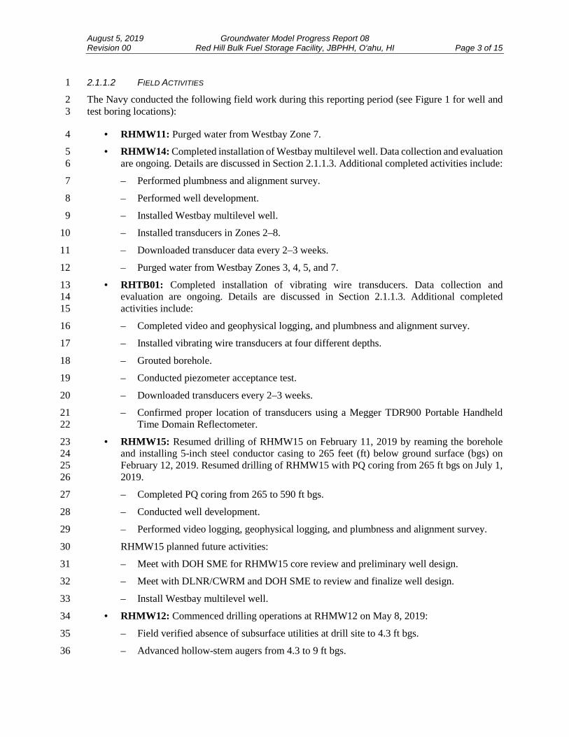
2.1.1.2 FIELD ACTIVITIES 1
The Navy conducted the following field work during this reporting period (see Figure 1 for well and 2 test boring locations): 3
RHMW11: Purged water from Westbay Zone 7. 4
RHMW14: Completed installation of Westbay multilevel well. Data collection and evaluation 5 are ongoing. Details are discussed in Section 2.1.1.3. Additional completed activities include: 6
– Performed plumbness and alignment survey. 7
– Performed well development. 8
– Installed Westbay multilevel well. 9
– Installed transducers in Zones 2–8. 10
– Downloaded transducer data every 2–3 weeks. 11
– Purged water from Westbay Zones 3, 4, 5, and 7. 12
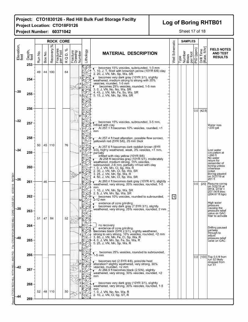
RHTB01: Completed installation of vibrating wire transducers. Data collection and 13 evaluation are ongoing. Details are discussed in Section 2.1.1.3. Additional completed 14 activities include: 15
– Completed video and geophysical logging, and plumbness and alignment survey. 16
– Installed vibrating wire transducers at four different depths. 17
– Grouted borehole. 18
– Conducted piezometer acceptance test. 19
– Downloaded transducers every 2–3 weeks. 20
– Confirmed proper location of transducers using a Megger TDR900 Portable Handheld 21 Time Domain Reflectometer. 22
RHMW15: Resumed drilling of RHMW15 on February 11, 2019 by reaming the borehole 23 and installing 5-inch steel conductor casing to 265 feet (ft) below ground surface (bgs) on 24 February 12, 2019. Resumed drilling of RHMW15 with PQ coring from 265 ft bgs on July 1, 25 2019. 26
– Completed PQ coring from 265 to 590 ft bgs. 27
– Conducted well development. 28
– Performed video logging, geophysical logging, and plumbness and alignment survey. 29
RHMW15 planned future activities: 30
– Meet with DOH SME for RHMW15 core review and preliminary well design. 31
– Meet with DLNR/CWRM and DOH SME to review and finalize well design. 32
– Install Westbay multilevel well. 33
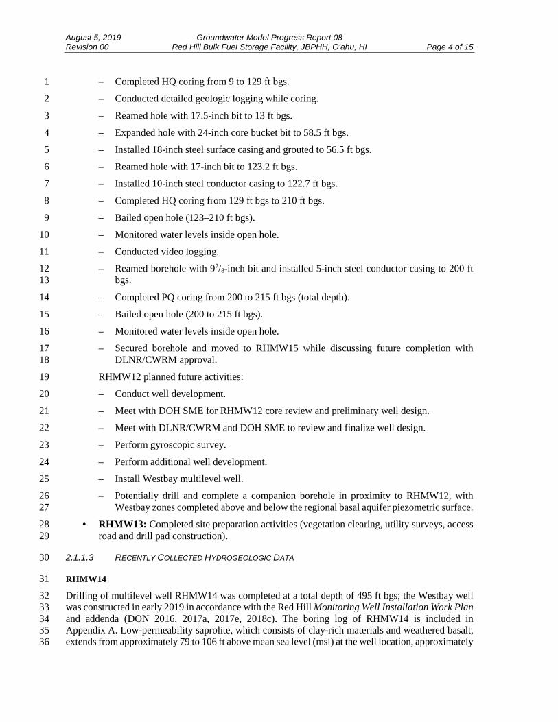
RHMW12: Commenced drilling operations at RHMW12 on May 8, 2019: 34
– Field verified absence of subsurface utilities at drill site to 4.3 ft bgs. 35
– Advanced hollow-stem augers from 4.3 to 9 ft bgs. 36
August 5, 2019 Groundwater Model Progress Report 08 Revision 00 Red Hill Bulk Fuel Storage Facility, JBPHH, O‘ahu, HI Page 4 of 15
– Completed HQ coring from 9 to 129 ft bgs. 1
– Conducted detailed geologic logging while coring. 2
– Reamed hole with 17.5-inch bit to 13 ft bgs. 3
– Expanded hole with 24-inch core bucket bit to 58.5 ft bgs. 4
– Installed 18-inch steel surface casing and grouted to 56.5 ft bgs. 5
– Reamed hole with 17-inch bit to 123.2 ft bgs. 6
– Installed 10-inch steel conductor casing to 122.7 ft bgs. 7
– Completed HQ coring from 129 ft bgs to 210 ft bgs. 8
– Bailed open hole (123–210 ft bgs). 9
– Monitored water levels inside open hole. 10
– Conducted video logging. 11
– Reamed borehole with 97/8-inch bit and installed 5-inch steel conductor casing to 200 ft 12 bgs. 13
– Completed PQ coring from 200 to 215 ft bgs (total depth). 14
– Bailed open hole (200 to 215 ft bgs). 15
– Monitored water levels inside open hole. 16
– Secured borehole and moved to RHMW15 while discussing future completion with 17 DLNR/CWRM approval. 18
RHMW12 planned future activities: 19
– Conduct well development. 20
– Meet with DOH SME for RHMW12 core review and preliminary well design. 21
– Meet with DLNR/CWRM and DOH SME to review and finalize well design. 22
– Perform gyroscopic survey. 23
– Perform additional well development. 24
– Install Westbay multilevel well. 25
– Potentially drill and complete a companion borehole in proximity to RHMW12, with 26 Westbay zones completed above and below the regional basal aquifer piezometric surface. 27
RHMW13: Completed site preparation activities (vegetation clearing, utility surveys, access 28 road and drill pad construction). 29
2.1.1.3 RECENTLY COLLECTED HYDROGEOLOGIC DATA 30
RHMW14 31
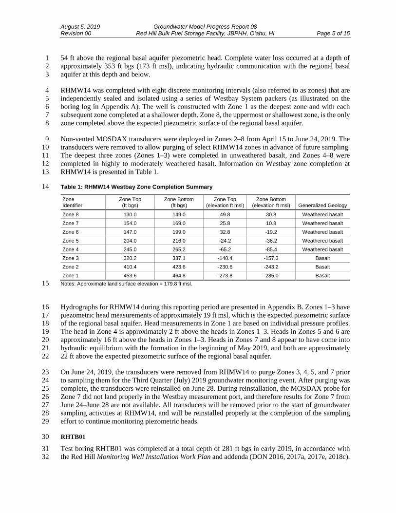
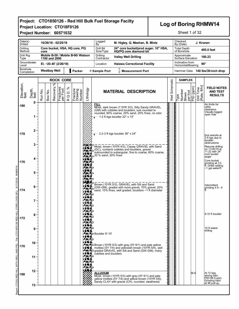
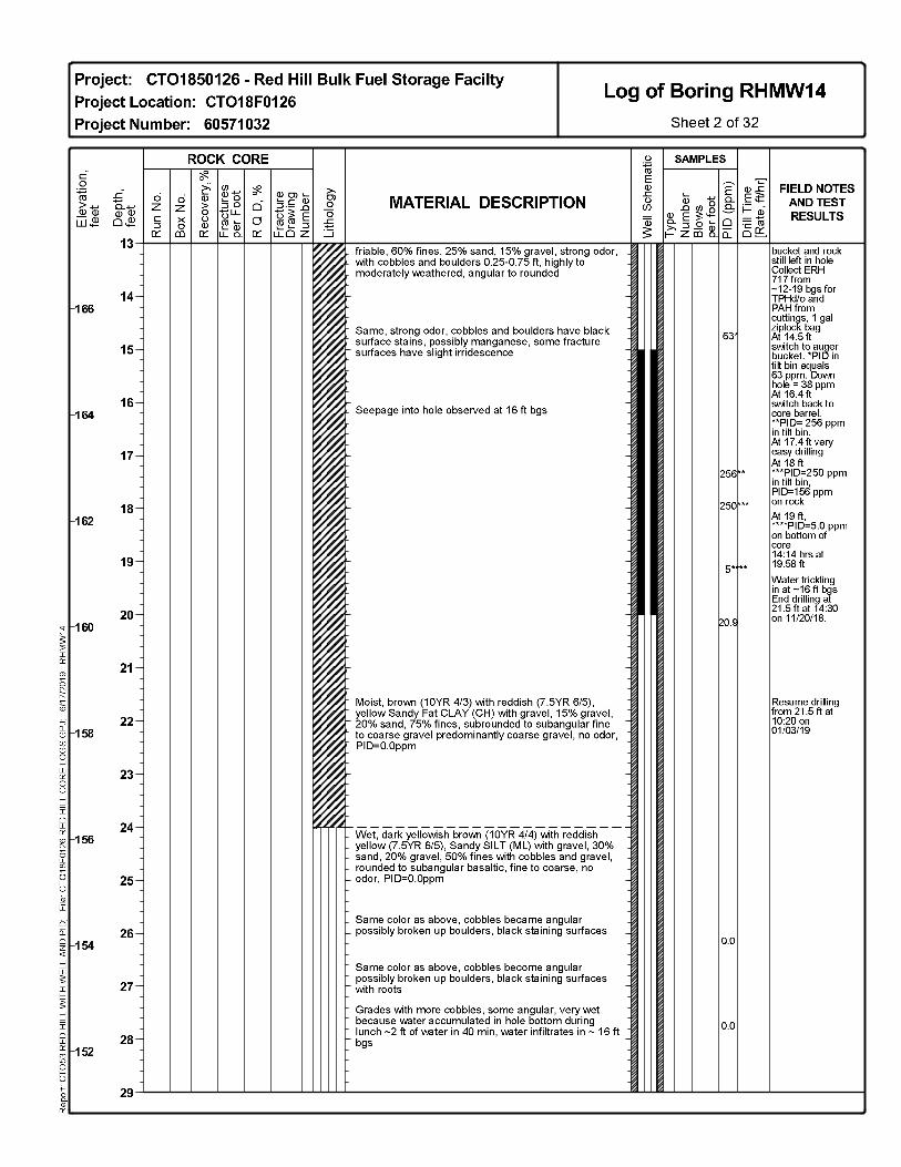
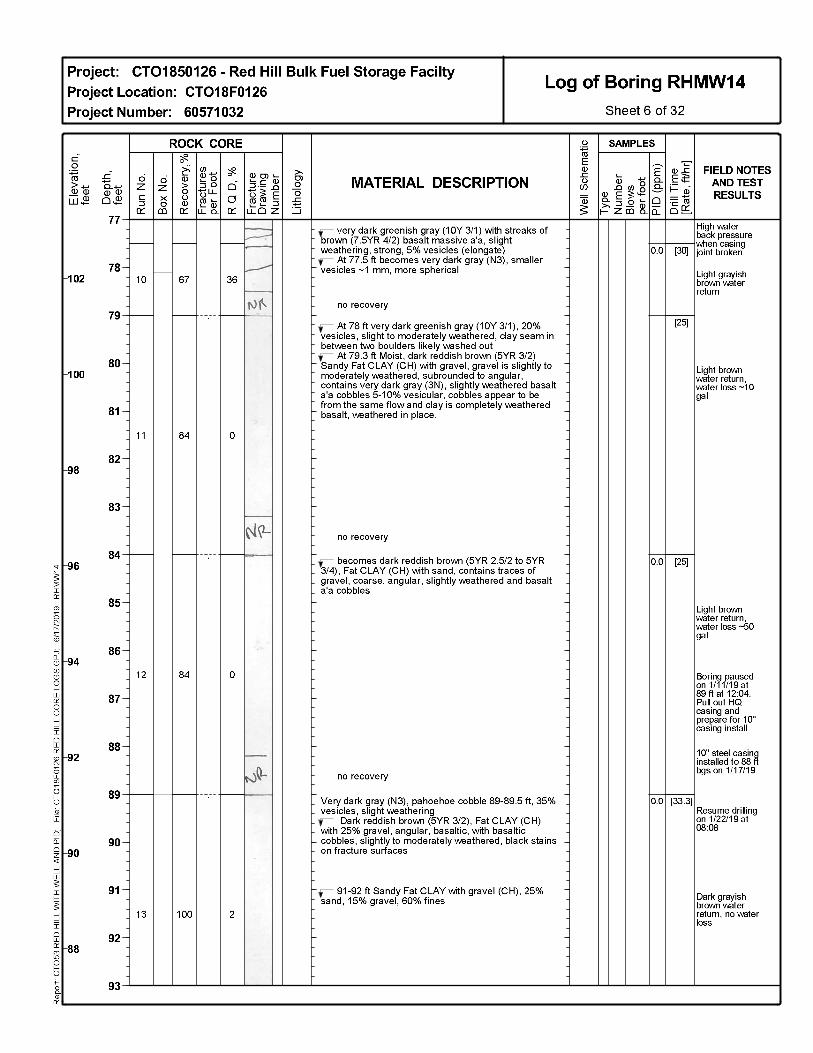
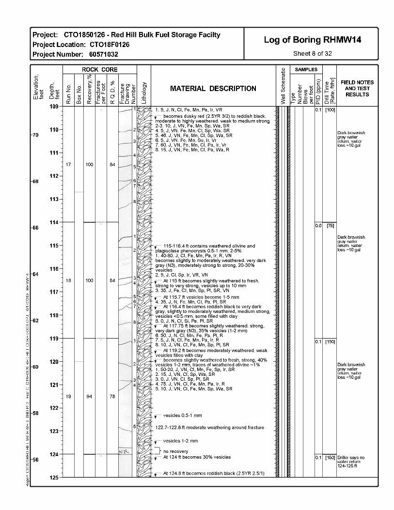
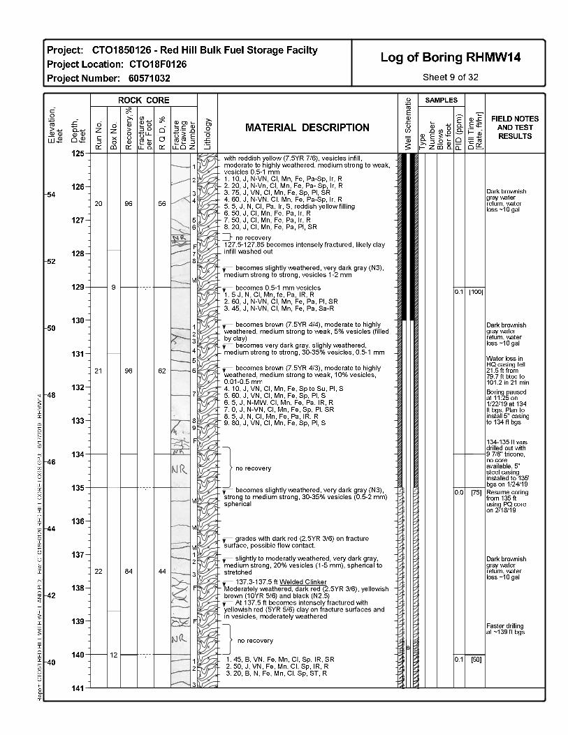
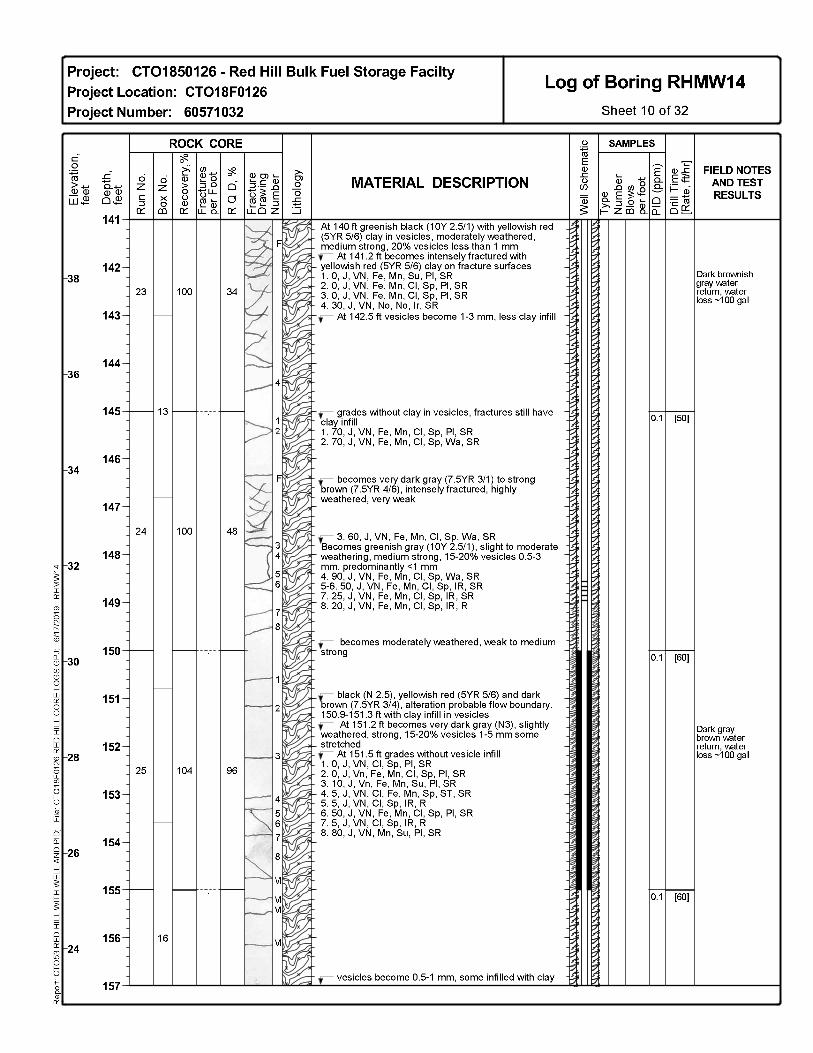
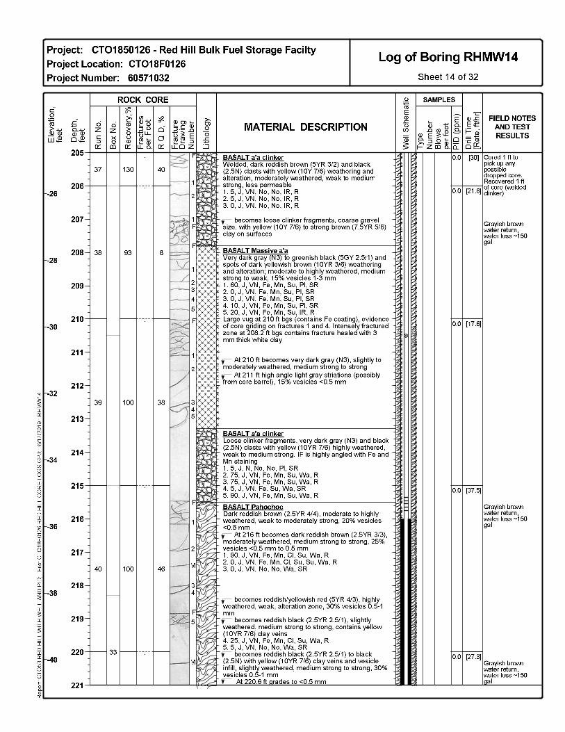
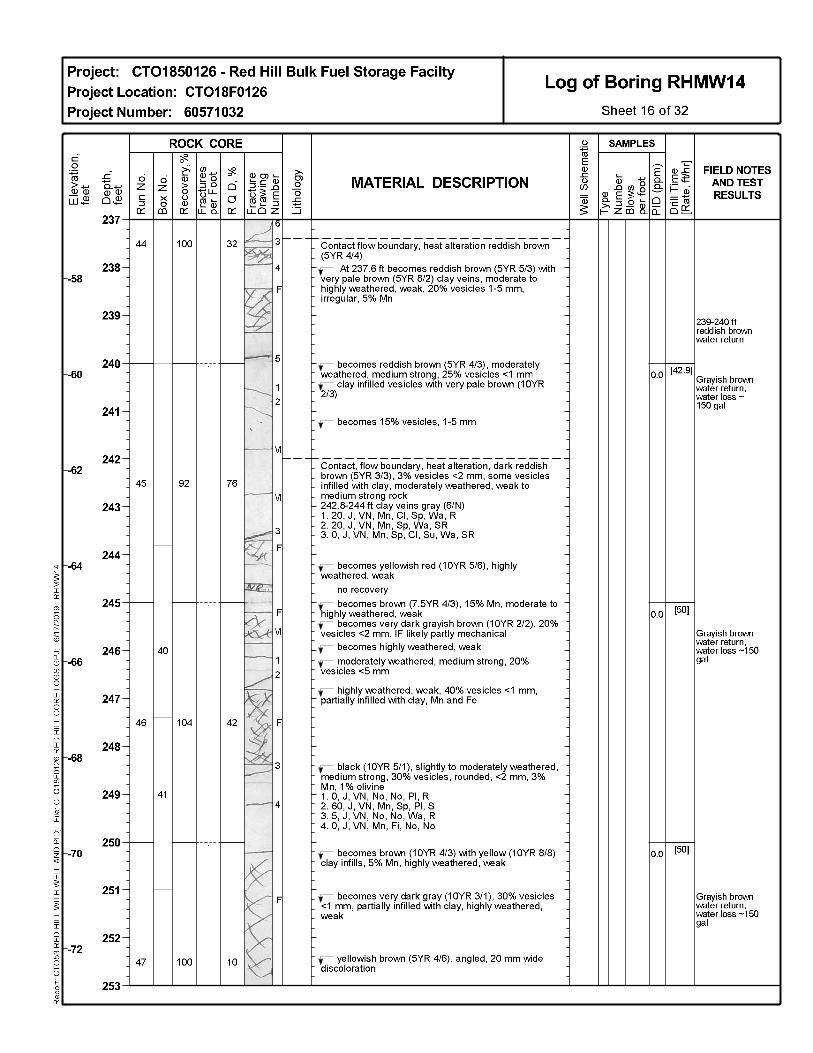
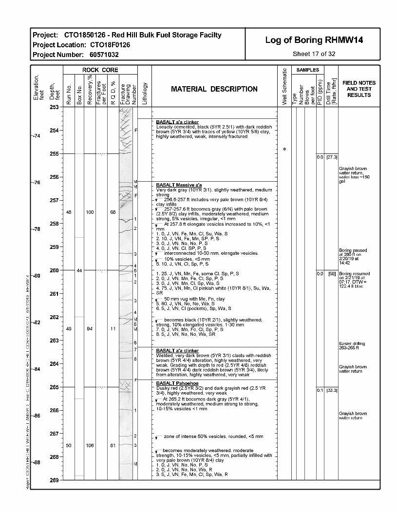
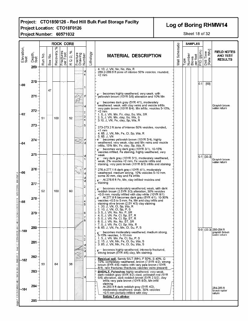
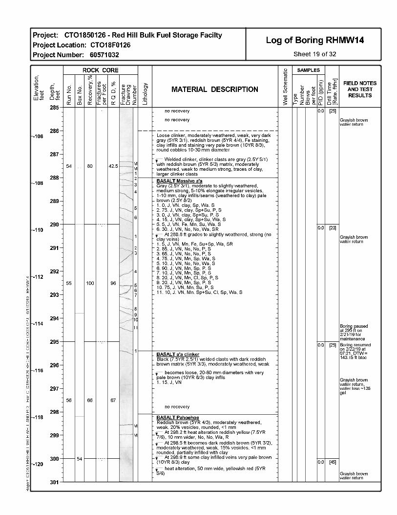
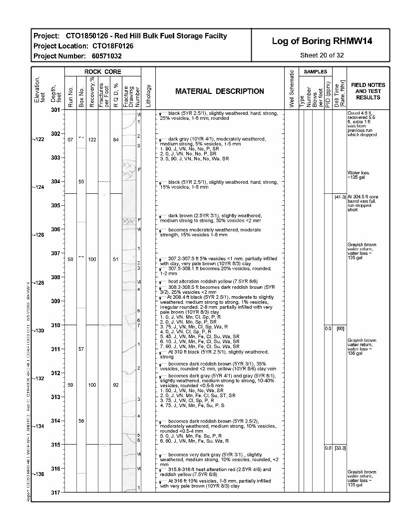
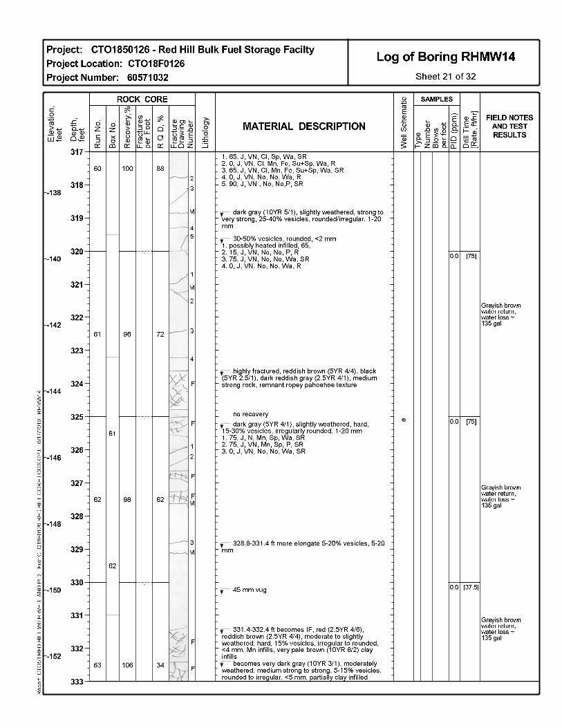
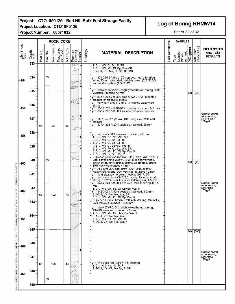
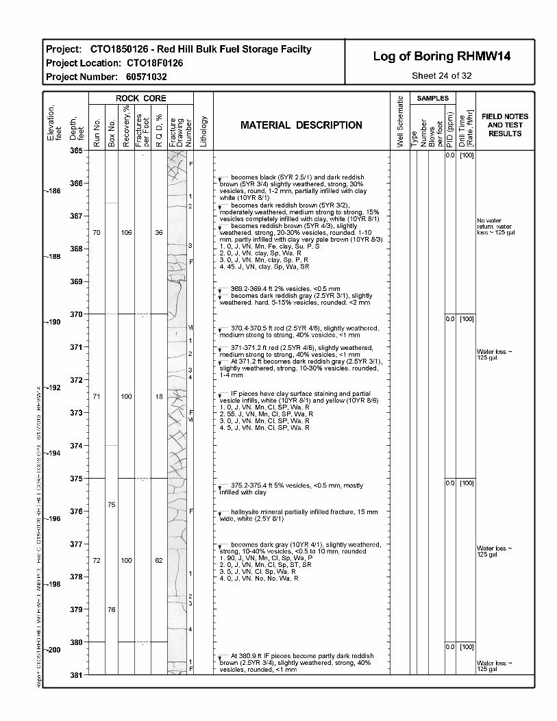
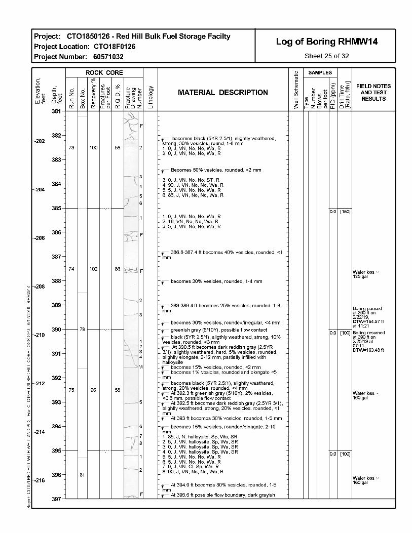
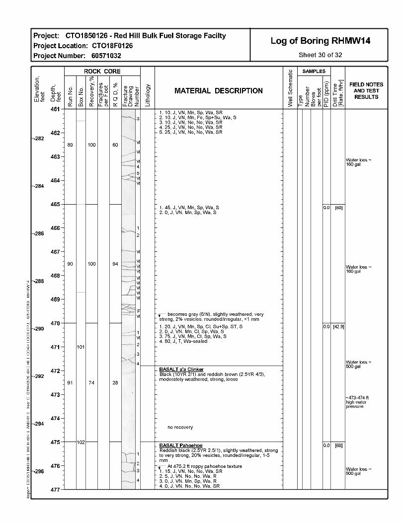
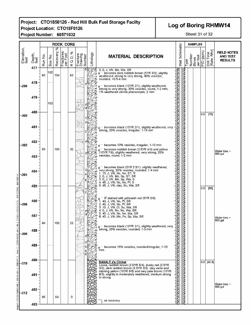
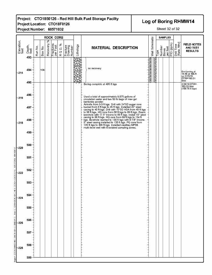
Drilling of multilevel well RHMW14 was completed at a total depth of 495 ft bgs; the Westbay well 32 was constructed in early 2019 in accordance with the Red Hill Monitoring Well Installation Work Plan 33 and addenda (DON 2016, 2017a, 2017e, 2018c). The boring log of RHMW14 is included in 34 Appendix A. Low-permeability saprolite, which consists of clay-rich materials and weathered basalt, 35 extends from approximately 79 to 106 ft above mean sea level (msl) at the well location, approximately 36
August 5, 2019 Groundwater Model Progress Report 08 Revision 00 Red Hill Bulk Fuel Storage Facility, JBPHH, O‘ahu, HI Page 5 of 15
54 ft above the regional basal aquifer piezometric head. Complete water loss occurred at a depth of 1 approximately 353 ft bgs (173 ft msl), indicating hydraulic communication with the regional basal 2 aquifer at this depth and below. 3
RHMW14 was completed with eight discrete monitoring intervals (also referred to as zones) that are 4 independently sealed and isolated using a series of Westbay System packers (as illustrated on the 5 boring log in Appendix A). The well is constructed with Zone 1 as the deepest zone and with each 6 subsequent zone completed at a shallower depth. Zone 8, the uppermost or shallowest zone, is the only 7 zone completed above the expected piezometric surface of the regional basal aquifer. 8
Non-vented MOSDAX transducers were deployed in Zones 2–8 from April 15 to June 24, 2019. The 9 transducers were removed to allow purging of select RHMW14 zones in advance of future sampling. 10 The deepest three zones (Zones 1–3) were completed in unweathered basalt, and Zones 4–8 were 11 completed in highly to moderately weathered basalt. Information on Westbay zone completion at 12 RHMW14 is presented in Table 1. 13
Table 1: RHMW14 Westbay Zone Completion Summary 14
Zone Identifier
Zone Top (ft bgs)
Zone Bottom (ft bgs)
Zone Top (elevation ft msl)
Zone Bottom (elevation ft msl) Generalized Geology
Zone 8 130.0 149.0 49.8 30.8 Weathered basalt Zone 7 154.0 169.0 25.8 10.8 Weathered basalt Zone 6 147.0 199.0 32.8 -19.2 Weathered basalt Zone 5 204.0 216.0 -24.2 -36.2 Weathered basalt Zone 4 245.0 265.2 -65.2 -85.4 Weathered basalt Zone 3 320.2 337.1 -140.4 -157.3 Basalt Zone 2 410.4 423.6 -230.6 -243.2 Basalt Zone 1 453.6 464.8 -273.8 -285.0 Basalt
Notes: Approximate land surface elevation = 179.8 ft msl. 15
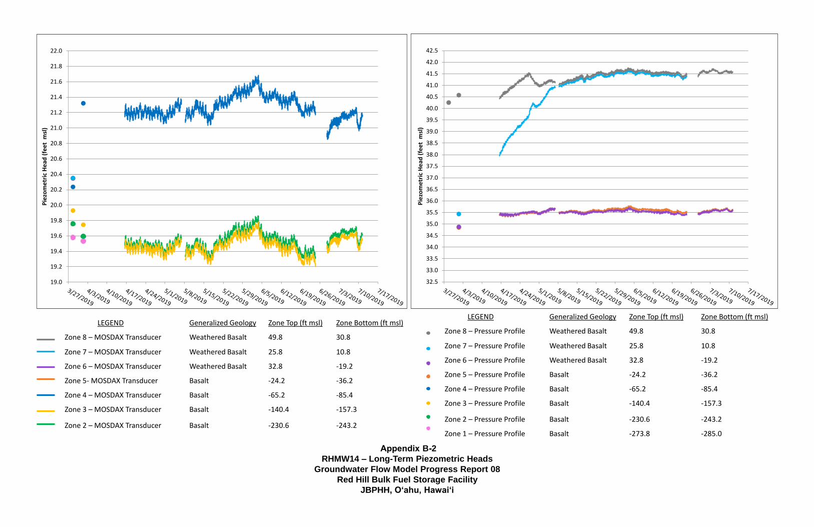
Hydrographs for RHMW14 during this reporting period are presented in Appendix B. Zones 1–3 have 16 piezometric head measurements of approximately 19 ft msl, which is the expected piezometric surface 17 of the regional basal aquifer. Head measurements in Zone 1 are based on individual pressure profiles. 18 The head in Zone 4 is approximately 2 ft above the heads in Zones 1–3. Heads in Zones 5 and 6 are 19 approximately 16 ft above the heads in Zones 1–3. Heads in Zones 7 and 8 appear to have come into 20 hydraulic equilibrium with the formation in the beginning of May 2019, and both are approximately 21 22 ft above the expected piezometric surface of the regional basal aquifer. 22
On June 24, 2019, the transducers were removed from RHMW14 to purge Zones 3, 4, 5, and 7 prior 23 to sampling them for the Third Quarter (July) 2019 groundwater monitoring event. After purging was 24 complete, the transducers were reinstalled on June 28. During reinstallation, the MOSDAX probe for 25 Zone 7 did not land properly in the Westbay measurement port, and therefore results for Zone 7 from 26 June 24–June 28 are not available. All transducers will be removed prior to the start of groundwater 27 sampling activities at RHMW14, and will be reinstalled properly at the completion of the sampling 28 effort to continue monitoring piezometric heads. 29
RHTB01 30
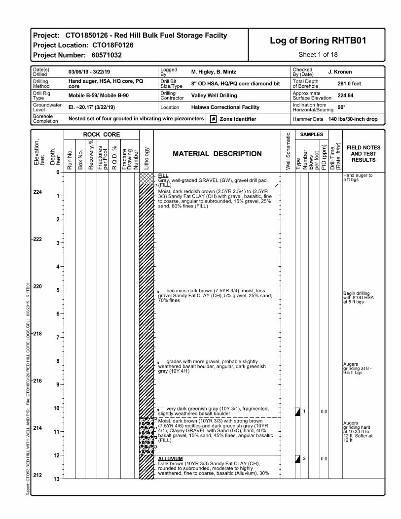
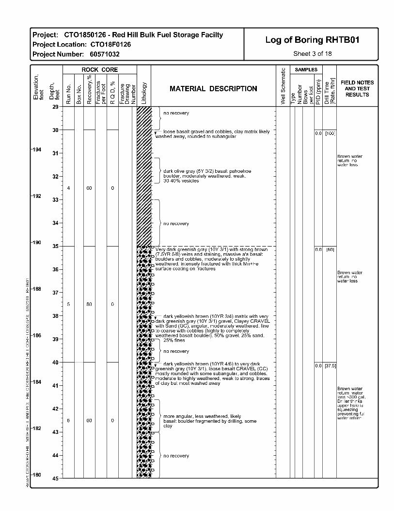
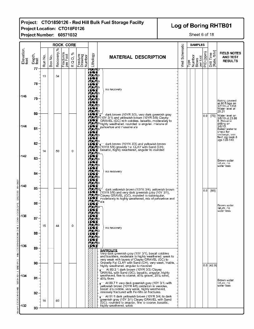
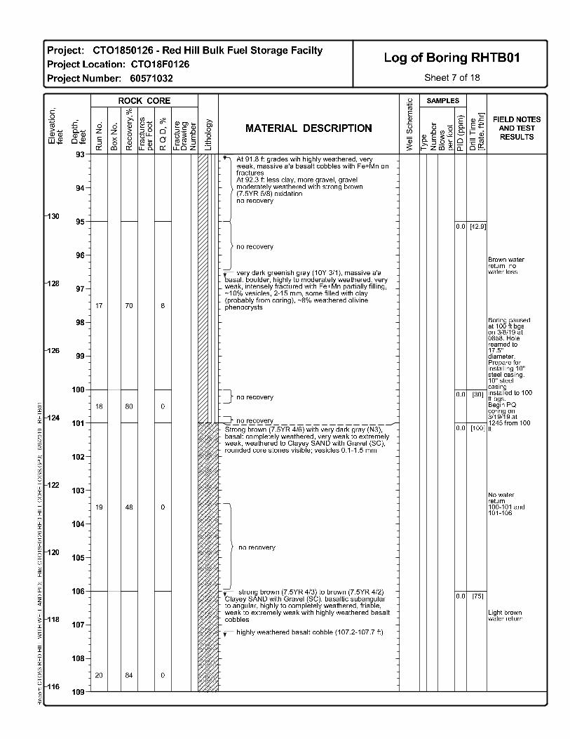
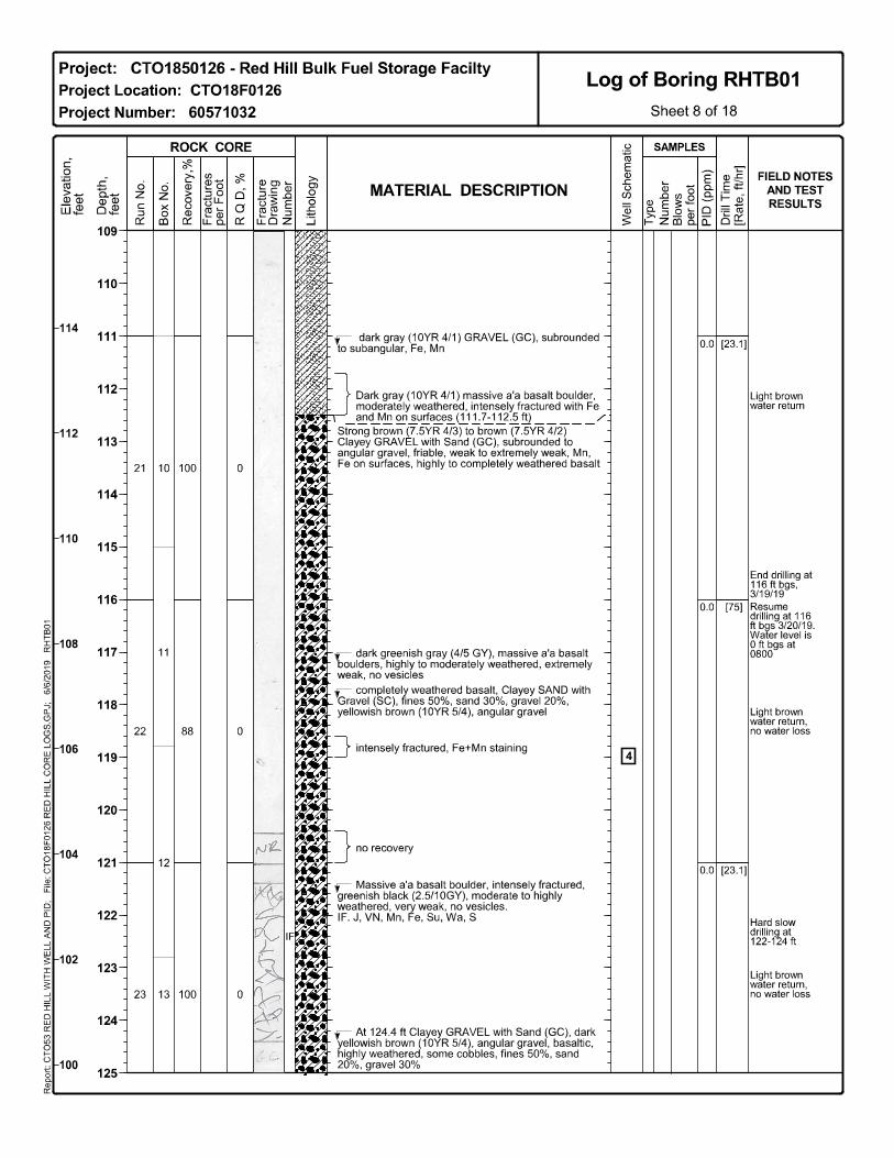
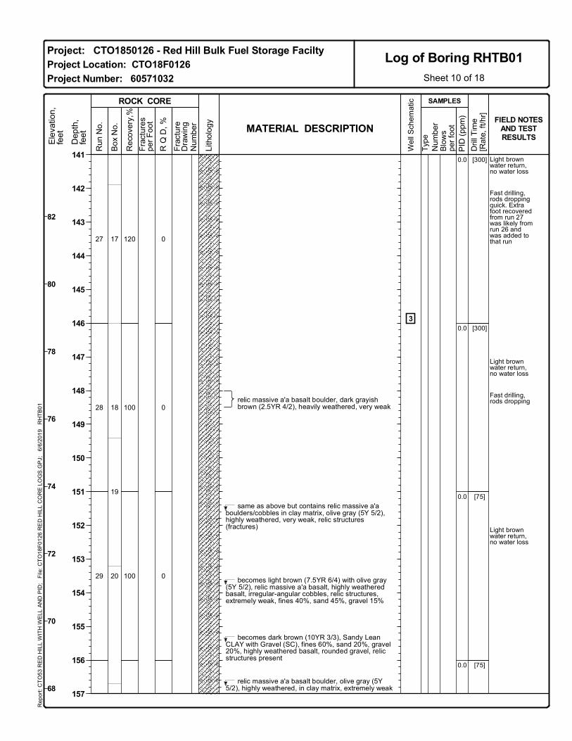
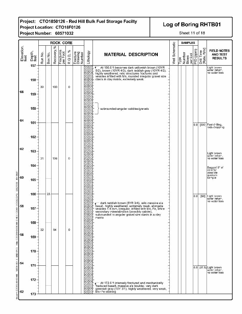
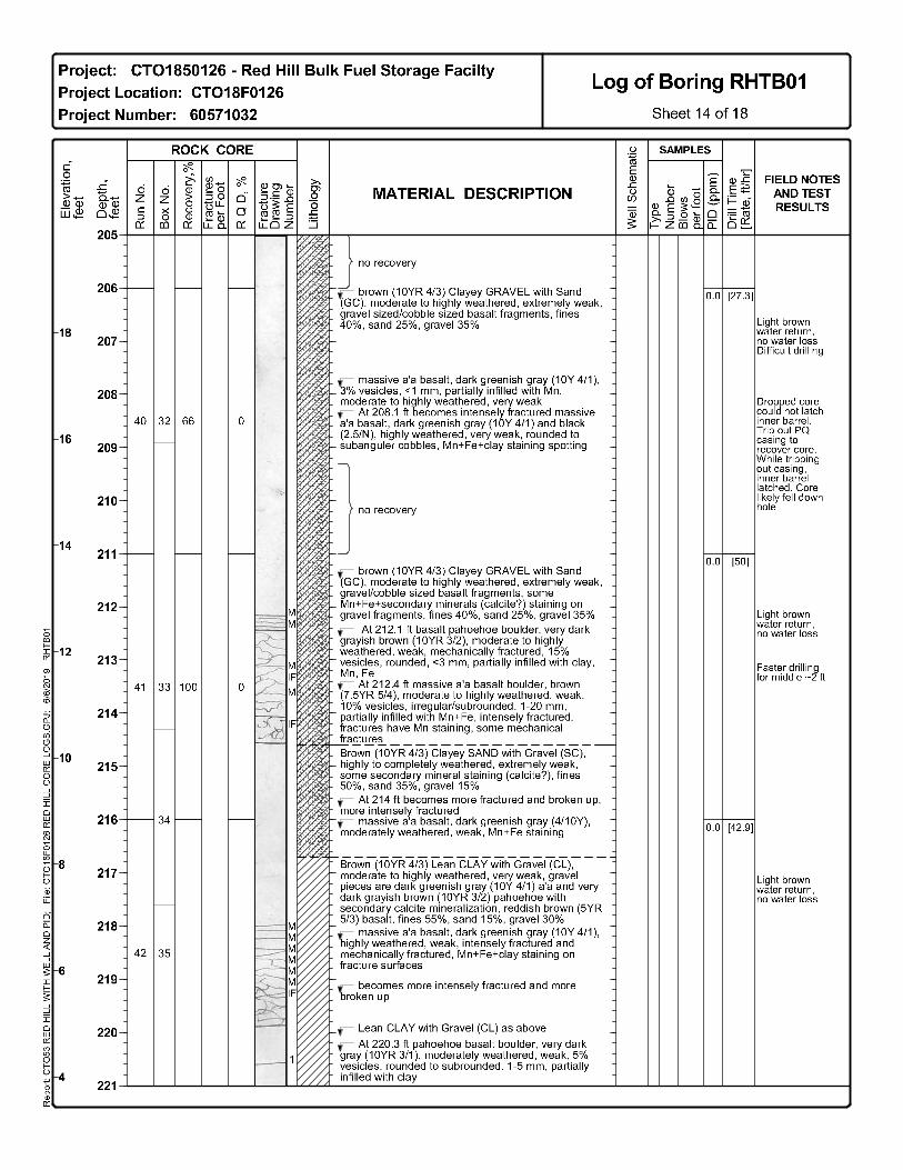
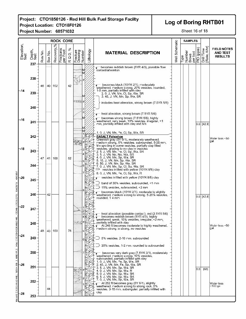
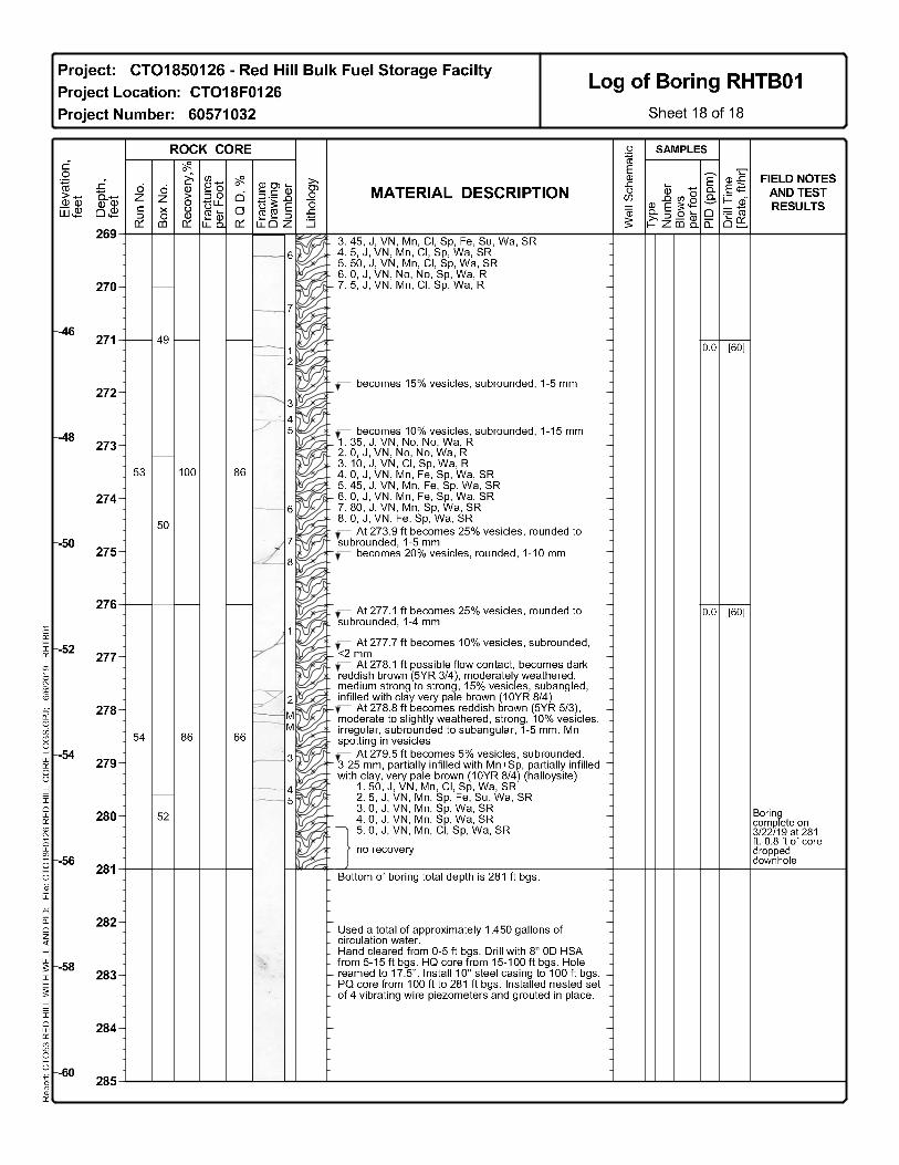
Test boring RHTB01 was completed at a total depth of 281 ft bgs in early 2019, in accordance with 31 the Red Hill Monitoring Well Installation Work Plan and addenda (DON 2016, 2017a, 2017e, 2018c). 32

August 5, 2019 Groundwater Model Progress Report 08 Revision 00 Red Hill Bulk Fuel Storage Facility, JBPHH, O‘ahu, HI Page 6 of 15
The boring log for RHTB01 is included in Appendix A. Low-permeability saprolite, which consists of 1 clay-rich materials and weathered basalt, extends from approximately 136 ft above msl to 17 ft below 2 msl at the boring location; the regional basal aquifer piezometric head is approximately 20 ft above 3 msl. Complete water loss occurred at approximately 260 ft bgs (-35 ft msl), indicating hydraulic 4 communication with the regional basal aquifer at this depth and below. 5
Four grouted-in-place vibrating wire piezometers were installed in the test boring in four separate 6 zones on March 29, 2019. Information on the piezometer zones is listed in Table 2. The depths of the 7 vibrating wire piezometers were confirmed with a Megger TDR900 Portable Handheld Time Domain 8 Reflectometer. The Zone 1 transducer was installed in unweathered basalt approximately 46 ft below 9 the regional basal aquifer piezometric head. Zones 2, 3, and 4 were installed in the saprolite, above the 10 regional basal aquifer. 11
Table 2: RHTB01 Grouted in Piezometer Zone Completion Summary 12
Zone Identifier Probe Elevation (ft msl) Generalized Geology
Zone 4 106 Saprolite Zone 3 79 Saprolite Zone 2 43 Saprolite Zone 1 -37 Basalt
Notes: Approximate land surface elevation = 225 ft msl. 13
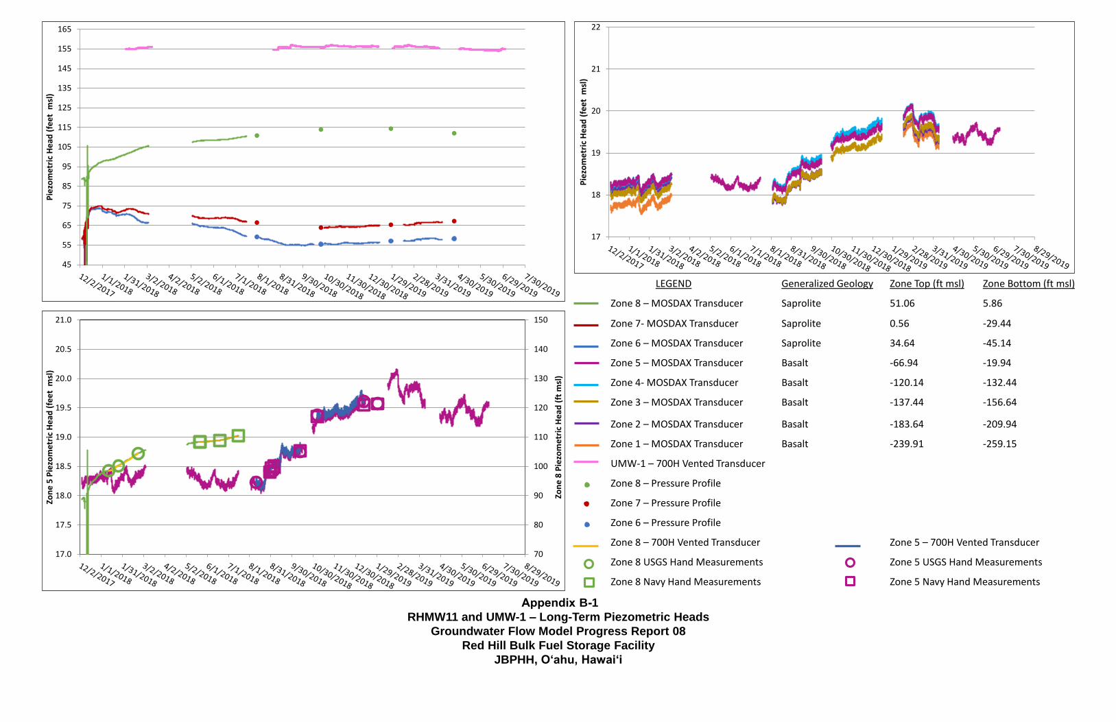
Hydrographs for RHTB01 during this reporting period are presented in Appendix B. The heads in all 14 four zones were declining based on the most recent data and may not have come into equilibrium with 15 the surrounding formations. Piezometric heads in Zone 1 were measured at -1 to 0 ft msl; prior to 16 installation of the grouted in piezometers, the heads in Zone 1 were anticipated to be at the piezometric 17 surface of the regional basal aquifer (approximately 20 ft msl). Piezometric heads at Zone 2 ranged 18 from 76 to 81 ft msl and were still declining as of the latest data download. Heads in Zone 3 (194–195 19 ft msl) were unexpectedly higher than heads in Zone 4 (134.5–135.5 ft msl). As stated above, it is not 20 believed that this is due to a misplacement or misidentification of the vibrating wire piezometer. While 21 additional monitoring is required, this may be evidence of variability in the perched zone(s) within the 22 valley fill. 23
RHMW11 24
A discussion on RHMW11 Westbay construction is presented in the CSM Revision 01 (DON 2019c). 25 Monitoring in RHMW11 used a non-vented MOSDAX pressure transducers in all eight zones and a 26 USGS 700H vented pressure transducer in the Westbay center tube. Monitoring was performed with 27 pumping port 8 open from January 12 to February 23, 2018, and with pumping port 5 open from 28 August 10, 2018 to July 2019. The pressure transducers were removed to facilitate quarterly 29 groundwater monitoring events. Groundwater levels in all zones appear to either have equilibrated or 30 are asymptotically approaching equilibration within the formations they are completed in. 31 Hydrographs for RHMW11 during this reporting period are presented in Appendix B. Data from 32 monitoring well UMW-1, located at the Hālawa Correctional Facility, have been added to these 33 hydrographs for comparison. 34
RHMW15 35
Drilling of multilevel well RHMW15 was completed at a total depth of 590 ft bgs, and the well was 36 constructed in July 2019 in accordance with the Red Hill Monitoring Well Installation Work Plan and 37 addenda (DON 2016, 2017a, 2017e, 2018c). A boring and well construction log of RHMW15 will be 38

August 5, 2019 Groundwater Model Progress Report 08 Revision 00 Red Hill Bulk Fuel Storage Facility, JBPHH, O‘ahu, HI Page 7 of 15
provided in the next Groundwater Model Progress Report. Low-permeability saprolite and residual 1 soil, which consists of clay-rich materials and weathered basalt, extends to only approximately 5 ft bgs 2 at the borehole location, approximately 285 ft above the regional basal aquifer piezometric head 3 (approximately 20 ft above msl). Complete water loss occurred at approximately 290 ft bgs (20 ft msl), 4 indicating hydraulic communication with the regional basal aquifer at this depth and below. 5
RHMW12 6
The RHMW12 borehole was completed at a total depth of 215 ft bgs in accordance with the Red Hill 7 Monitoring Well Installation Work Plan and addenda (DON 2016, 2017a, 2017e, 2018c). A boring log 8 of RHMW12 will be provided in the next Groundwater Model Progress Report. Alluvium, including 9 weathered clays and weathered basalt, extends to approximately 59 ft bgs, approximately 178.5 ft 10 above msl at the borehole location. During drilling, complete water loss did not occur, indicating that 11 the depth where there is hydraulic communication with the regional basal aquifer was not reached. 12
2.1.1.4 THERMAL PROFILING 13
The Navy conducted vertical thermal profiling in ten monitoring wells during April 29 – May 2, 2019 14 to facilitate evaluation of the stability of the thermal data in wells underlying the tank farm and how 15 they may contrast with areas outside the tank farm. The results will be presented in the forthcoming 16 Investigation and Remediation of Releases (IRR) Report. 17
2.1.1.5 GROUNDWATER MODELING 18
The Navy conducted the following groundwater modeling activities this reporting period: 19
Held weekly groundwater modeling team progress meetings to establish short-term milestones 20 and resolve technical issues as they arose. 21
Targets within connected linear network (CLN) nodes (e.g., Red Hill Shaft) were not passed 22 from MODFLOW (the code that does the groundwater flow calculations) to PEST (Parameter 23 Estimation software, the code that assists in the calibration process). Worked with Aquaveo 24 (GMS modeling software vendor) to diagnose and correct PEST file-creation errors. 25 Developed a workaround to create correct PEST files and maintain forward progress while the 26 vendor investigated and corrected the issue. 27
Refined and performed quality control (QC) on calibration targets derived from the transfer 28 function-noise (TFN) analysis. The first 15 days after a pumping change are being simulated 29 and compared to TFN-derived targets. 30
Revised representation of Red Hill Shaft and Hālawa Shaft geometry to match as-built 31 drawings and assigned CLN nodes to appropriate model layers based on as-built elevations. 32
Revised and performed QC on calibration targets derived from the TFN analysis. Initially, the 33 previous targets were not based on the TFN results. The TFN analysis went through multiple 34 revisions, resulting in additional revisions to the targets. This provides drastically reduced 35 model run times when calibrating to one “pure” aquifer response to pumping at each pumping 36 center, as compared to simulating dozens of on/off cycles with confounding effects from 37 weather and non-coordinated interfering pumping at other locations. 38
Reviewed and performed QC on the process and tools used to calibrate directly to drawdowns 39 and head differences between wells, in addition to absolute elevation heads. This enables 40 focusing of the calibration effort directly on aquifer responses to pumping and gradient 41 magnitudes, with less effort spent on elevation-survey quality and precision issues. 42
August 5, 2019 Groundwater Model Progress Report 08 Revision 00 Red Hill Bulk Fuel Storage Facility, JBPHH, O‘ahu, HI Page 8 of 15
Developing this process and these tools was necessary because the groundwater modeling 1 graphical user interface does not support use of drawdown as a calibration target. 2
Developed head-difference targets between well pairs to improve the modeling team’s ability 3 to evaluate gradients and the team’s ability to direct PEST to emphasize matching those 4 differences. Developed a utility to compute the simulated differences from MODFLOW 5 output so that PEST can evaluate the differences during the calibration process. 6
Performed transient model calibration runs with PEST for two alternative saprolite 7 interpretations. Each PEST run consists of several hundred MODFLOW runs. Comparing 8 calibration quality of the two interpretations is currently in progress. 9
Through the calibration process, identified that a homogeneous basalt hydraulic conductivity 10 distribution (identical permeability at Red Hill Shaft and Hālawa Shaft) appears incapable of 11 closely matching pumping responses at both Red Hill Shaft and Hālawa Shaft. This suggests 12 that at a minimum, these two areas require separate hydraulic conductivity zones. 13
Developed a model using a heterogeneous basalt hydraulic conductivity distribution. Several 14 dozen pilot points (with greater density at the site) are used to define the hydraulic conductivity 15 field through the autocalibration process. The heterogeneous basalt calibration is currently in 16 progress. 17
Used the Geometric Mean Scheme (GMS) Tikhonov regularization implementation to define 18 a preferred condition of homogeneity for the heterogeneous model (i.e., only the minimum 19 necessary heterogeneity should be added by PEST). For all other parameters, developed 20 preferred-value regularization targets to stabilize the parameter-estimation process. Adding 21 regularization reduces PEST’s incentive to (e.g.) adjust hydraulic conductivity by a factor of 22 100 to achieve a 0.001-ft improvement to a single target, and reduces the likelihood of PEST 23 assigning extreme values to aquifer parameters. 24
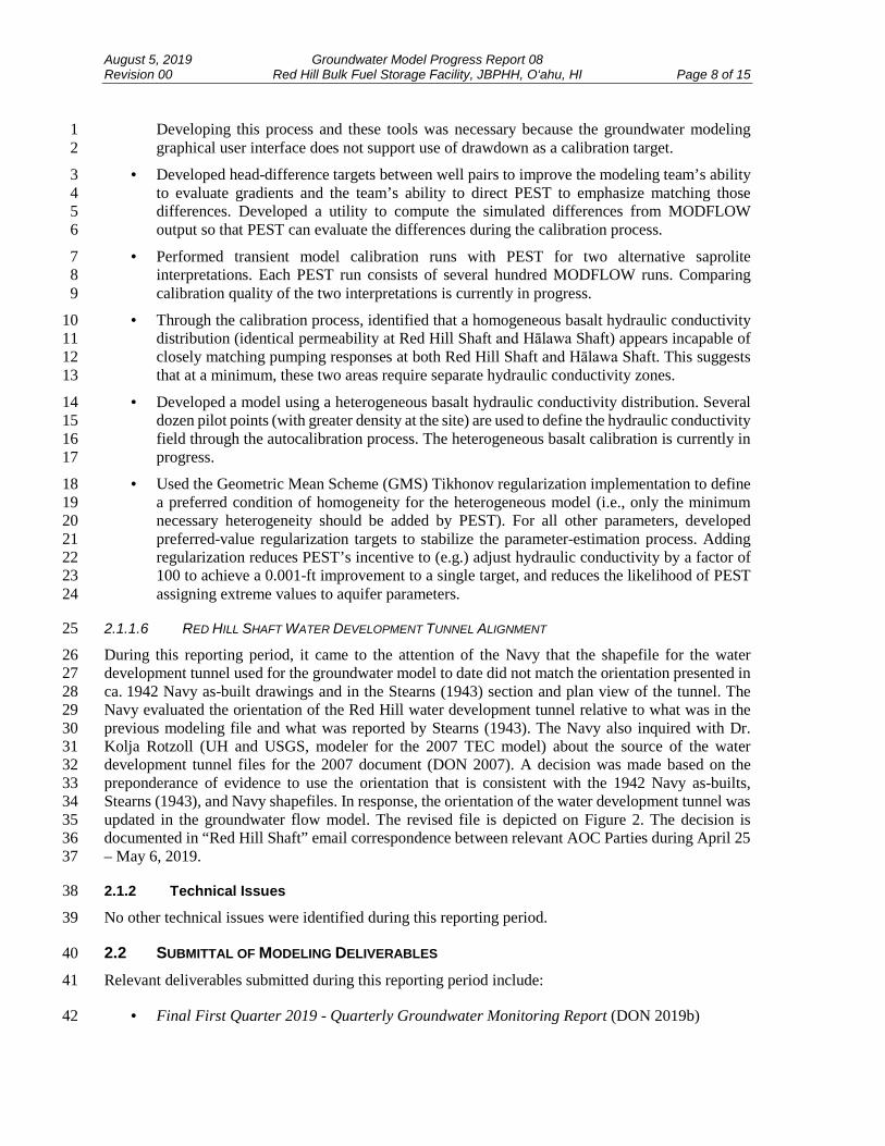
2.1.1.6 RED HILL SHAFT WATER DEVELOPMENT TUNNEL ALIGNMENT 25
During this reporting period, it came to the attention of the Navy that the shapefile for the water 26 development tunnel used for the groundwater model to date did not match the orientation presented in 27 ca. 1942 Navy as-built drawings and in the Stearns (1943) section and plan view of the tunnel. The 28 Navy evaluated the orientation of the Red Hill water development tunnel relative to what was in the 29 previous modeling file and what was reported by Stearns (1943). The Navy also inquired with Dr. 30 Kolja Rotzoll (UH and USGS, modeler for the 2007 TEC model) about the source of the water 31 development tunnel files for the 2007 document (DON 2007). A decision was made based on the 32 preponderance of evidence to use the orientation that is consistent with the 1942 Navy as-builts, 33 Stearns (1943), and Navy shapefiles. In response, the orientation of the water development tunnel was 34 updated in the groundwater flow model. The revised file is depicted on Figure 2. The decision is 35 documented in “Red Hill Shaft” email correspondence between relevant AOC Parties during April 25 36 – May 6, 2019. 37
2.1.2 Technical Issues 38
No other technical issues were identified during this reporting period. 39
2.2 SUBMITTAL OF MODELING DELIVERABLES 40
Relevant deliverables submitted during this reporting period include: 41
Final First Quarter 2019 - Quarterly Groundwater Monitoring Report (DON 2019b) 42

August 5, 2019 Groundwater Model Progress Report 08 Revision 00 Red Hill Bulk Fuel Storage Facility, JBPHH, O‘ahu, HI Page 9 of 15
CSM Revision 01 (DON 2019c)1
3. Anticipated Work for Next Reporting Period2
Anticipated work for upcoming Reporting Period 09 (July 16 – November 15, 2019) includes: 3
Continue to download and evaluate data from RHMW11, RHMW14, and RHTB01.4
Complete RHMW12 and potential proximal companion well.5
Continue drilling and monitoring well installation efforts.6
Conduct Third and Fourth Quarter 2019 quarterly groundwater monitoring events.7
Continue groundwater flow modeling.8
Prepare October 2019 Groundwater Flow Model Report.9
Prepare October 2019 IRR Report.10
Potentially perform simplified 3D LNAPL modeling based on discussions with AOC Parties11 and Navy senior management.12
Anticipated deliverables due during upcoming Reporting Period 09 (July 16 – November 15, 2019) 13 include: 14
Final Second Quarter 2019 - Quarterly Groundwater Monitoring Report15
Draft Third Quarter 2019 - Quarterly Groundwater Monitoring Report16
Groundwater Flow Model Report, Revision 0017
Investigation and Remediation of Releases Report, Revision 0018
4. References19
Department of the Navy (DON). 2007. Red Hill Bulk Fuel Storage Facility Final Technical Report, 20 Pearl Harbor, Hawaii. Prepared by TEC, Inc. Pearl Harbor, HI: Naval Facilities Engineering 21 Command, Pacific. August. 22
———. 2014. Interim Update, Red Hill Bulk Fuel Storage Facility Final Groundwater Protection 23 Plan, Pearl Harbor, Hawaii. (January 2008). Pearl Harbor, HI: Naval Facilities Engineering 24 Command, Pacific. August. 25
———. 2016. Monitoring Well Installation Work Plan, Red Hill Bulk Fuel Storage Facility, Joint 26 Base Pearl Harbor-Hickam, O‘ahu, Hawai‘i; August 29, 2016. Prepared by AECOM Technical 27 Services, Inc., Honolulu, HI. Prepared for Defense Logistics Agency Energy, Fort Belvoir, VA, 28 under Naval Facilities Engineering Command, Hawaii, JBPHH HI. 29
———. 2017a. Monitoring Well Installation Work Plan Addendum 01, Red Hill Bulk Fuel Storage 30 Facility, Joint Base Pearl Harbor-Hickam, O‘ahu, Hawai‘i; January 4, 2017, Revision 00. 31 Prepared by AECOM Technical Services, Inc., Honolulu, HI. Prepared for Defense Logistics 32 Agency Energy, Fort Belvoir, VA, under Naval Facilities Engineering Command, Hawaii, JBPHH 33 HI. 34
August 5, 2019 Groundwater Model Progress Report 08 Revision 00 Red Hill Bulk Fuel Storage Facility, JBPHH, O‘ahu, HI Page 10 of 15
———. 2017b. Work Plan / Scope of Work, Investigation and Remediation of Releases and 1 Groundwater Protection and Evaluation, Red Hill Bulk Fuel Storage Facility, Joint Base Pearl 2 Harbor-Hickam, O‘ahu, Hawai‘i; January 4, 2017, Revision 02. Prepared by AECOM Technical 3 Services, Inc., Honolulu, HI. Prepared for Defense Logistics Agency Energy, Fort Belvoir, VA, 4 under Naval Facilities Engineering Command, Hawaii, JBPHH HI. 5
———. 2017c. Groundwater Flow Model Progress Report 01, Red Hill Bulk Fuel Storage Facility, 6 Joint Base Pearl Harbor-Hickam, O‘ahu, Hawai‘i; April 5, 2017, Revision 00. Prepared by 7 AECOM Technical Services, Inc., Honolulu, HI. Prepared for Defense Logistics Agency Energy, 8 Fort Belvoir, VA, under Naval Facilities Engineering Command, Hawaii, JBPHH HI. 9
———. 2017d. Groundwater Flow Model Progress Report 02, Red Hill Bulk Fuel Storage Facility, 10 Joint Base Pearl Harbor-Hickam, O‘ahu, Hawai‘i; August 4, 2017, Revision 00. Prepared by 11 AECOM Technical Services, Inc., Honolulu, HI. Prepared for Defense Logistics Agency Energy, 12 Fort Belvoir, VA, under Naval Facilities Engineering Command, Hawaii, JBPHH HI. 13
———. 2017e. Monitoring Well Installation Work Plan Addendum 02, Investigation and Remediation 14 of Releases and Groundwater Protection and Evaluation, Red Hill Bulk Fuel Storage Facility, 15 Joint Base Pearl Harbor-Hickam, O‘ahu, Hawai‘i; August 25, 2017, Revision 00. Prepared by 16 AECOM Technical Services, Inc., Honolulu, HI. Prepared for Defense Logistics Agency Energy, 17 Fort Belvoir, VA, under Naval Facilities Engineering Command, Hawaii, JBPHH HI. 18
———. 2017f. Groundwater Flow Model Progress Report 03, Red Hill Bulk Fuel Storage Facility, 19 Joint Base Pearl Harbor-Hickam, O‘ahu, Hawai‘i; December 3, 2017, Revision 00. Prepared by 20 AECOM Technical Services, Inc., Honolulu, HI. Prepared for Defense Logistics Agency Energy, 21 Fort Belvoir, VA, under Naval Facilities Engineering Command, Hawaii, JBPHH HI. 22
———. 2018a. Groundwater Flow Model Progress Report 04, Red Hill Bulk Fuel Storage Facility, 23 Joint Base Pearl Harbor-Hickam, O‘ahu, Hawai‘i; April 5, 2018, Revision 00. Prepared by 24 AECOM Technical Services, Inc., Honolulu, HI. Prepared for Defense Logistics Agency Energy, 25 Fort Belvoir, VA, under Naval Facilities Engineering Command, Hawaii, JBPHH HI. 26
———. 2018b. Groundwater Flow Model Progress Report 05, Red Hill Bulk Fuel Storage Facility, 27 Joint Base Pearl Harbor-Hickam, O‘ahu, Hawai‘i; August 3, 2018, Revision 00. Prepared by 28 AECOM Technical Services, Inc., Honolulu, HI. Prepared for Defense Logistics Agency Energy, 29 Fort Belvoir, VA, under Naval Facilities Engineering Command, Hawaii, JBPHH HI. 30
———. 2018c. Monitoring Well Installation Work Plan Addendum 03, Investigation and Remediation 31 of Releases and Groundwater Protection and Evaluation, Red Hill Bulk Fuel Storage Facility, 32 Joint Base Pearl Harbor-Hickam, O‘ahu, Hawai‘i; November 1, 2018, Revision 00. Internal 33 Review Draft. Prepared by AECOM Technical Services, Inc., Honolulu, HI. Prepared for Defense 34 Logistics Agency Energy, Fort Belvoir, VA, under Naval Facilities Engineering Command, 35 Hawaii, JBPHH HI. 36
———. 2018d. Groundwater Flow Model Progress Report 06, Red Hill Bulk Fuel Storage Facility, 37 Joint Base Pearl Harbor-Hickam, O‘ahu, Hawai‘i; December 4, 2018, Revision 00. Prepared by 38 AECOM Technical Services, Inc., Honolulu, HI. Prepared for Defense Logistics Agency Energy, 39 Fort Belvoir, VA, under Naval Facilities Engineering Command, Hawaii, JBPHH HI. 40

August 5, 2019 Groundwater Model Progress Report 08 Revision 00 Red Hill Bulk Fuel Storage Facility, JBPHH, O‘ahu, HI Page 11 of 15
———. 2019a. Groundwater Model Progress Report 07, Red Hill Bulk Fuel Storage Facility, Joint 1 Base Pearl Harbor-Hickam, O‘ahu, Hawai‘i; April 3, 2019, Revision 00. Prepared by AECOM 2 Technical Services, Inc., Honolulu, HI. Prepared for Defense Logistics Agency Energy, Fort 3 Belvoir, VA, under Naval Facilities Engineering Command, Hawaii, JBPHH HI. 4
———. 2019b. Final First Quarter 2019 - Quarterly Groundwater Monitoring Report, Red Hill Bulk 5 Fuel Storage Facility, Joint Base Pearl Harbor-Hickam, Oʻahu, Hawaiʻi. Prepared by AECOM 6 Technical Services, Inc. JBPHH HI: Naval Facilities Engineering Command, Hawaii. May. 7
———. 2019c. Conceptual Site Model, Investigation and Remediation of Releases and Groundwater 8 Protection and Evaluation, Red Hill Bulk Fuel Storage Facility, Joint Base Pearl Harbor-Hickam, 9 O‘ahu, Hawai‘i; June 30, 2019, Revision 01. Prepared by AECOM Technical Services, Inc., 10 Honolulu, HI. Prepared for Defense Logistics Agency Energy, Fort Belvoir, VA, under Naval 11 Facilities Engineering Command, Hawaii, JBPHH HI. 12
———. 2019d. Final Second Quarter 2019 - Quarterly Groundwater Monitoring Report, Red Hill 13 Bulk Fuel Storage Facility, Joint Base Pearl Harbor-Hickam, Oʻahu, Hawaiʻi. Prepared by 14 AECOM Technical Services, Inc. JBPHH HI: Naval Facilities Engineering Command, Hawaii. 15 August. 16
Environmental Protection Agency, United States, Region 9; and Department of Health, State of Hawaii 17 (EPA Region 9 and DOH). 2015. Administrative Order on Consent In the Matter of Red Hill Bulk 18 Fuel Storage Facility, EPA Docket No: RCRA 7003-R9-2015-01; DOH Docket No: 15-UST-EA-19 01. September. 20
———. 2016. “Conditional Approval of Red Hill AOC SOW Deliverable under Sections 6 & 7 - 21 Work Plan/Scope of Work, Investigation and Remediation of Releases and Groundwater 22 Protection and Evaluation, Red Hill Bulk Fuel Storage Facility, November 5, 2016 Revision 01.” 23 Letter from Bob Pallarino, EPA Red Hill Project Coordinator, and Steven Chang, DOH Red Hill 24 Project Coordinator, to: Captain Richard D. Hayes, Navy Region Hawaii. December 2, 2016. 25
Mitchell, J. N., and D. S. Oki. 2018. Groundwater-Level, Groundwater-Temperature, and Barometric-26 Pressure Data, July 2017 to February 2018, Hālawa Area, O‘ahu, Hawai‘i. Open-File Report 27 2018–1147. Prepared in Cooperation with the U.S. Navy. Reston, VA: U.S. Geological Survey. 28
Stearns, H. T. 1943. “Letter from H. T. Stearns, Senior Geologist, U.S. Geological Survey, to: O. E. 29 Meinzer, Division of Ground Water, U.S. Geological Survey, Washington, DC,” January 18, 1943. 30
United States Geological Survey (USGS). 2017. Final Synoptic Water Level Study Work Plan, Hālawa 31 Area, Oʻahu, Hawaiʻi. Honolulu, HI: Pacific Islands Water Science Center. August 10. 32

This page intentionally left blank

Notes
RHMW17
RHMW13
RHMW14
RHMW18
RHMW19
RHMW07D
RHMW01R
RHTB01
HālawaIndustrial
Park
HālawaCorrectional
Facility
MoanaluaGolf
Course
MoanaluaValley
H-201 Freew
ay
yawee
Fr3
H-
Āliamanu Crater
U.S. CoastGuard Housing
Moanalua HillsideApartments
MoanaluaVillage
Red Hill Elementary School
Tripler Army Medical Center
HālawaQuarry
Navy Firing Range
RHMW04
RHMW06
RHMW07
RHMW03
RHMW02
RHMW05
OWDFMW01
HDMW2253-03
maerSt
alu
an
ao
M
Oily WasteDisposalFacility
RHMW08
RHMW09
RHMW10
SouthHālawaValley
NorthHālawaValley
AnimalQuarantine
Station
BWS Hālawa Shaft(Well 2354-01)
RHMW11
a mtl
Hā awa S re
h
u
t
oS
RHMW01 &
m
aert
Sa
wal
āH
htr
oN
RHMW15
RHMW12 *
Navy Red Hill Shaft(Well 2254-01) &
RHMW2254-01
UMW-1
082
063
032
200
400
042
044
048
025
061
80
056
006
021
064
068
720
06
7
800
840
880
029
88
0
044
086
036
063
065
440
00
6
320
600
360
400
320
056
08
04
6
280
600
680
006
640
08
840
200
002
920
120
068
067
360
520
640
720
004
400
440
004
280
720
360
082
06
3
04
2
025
16
0
360
025
240
480
06
1
160
046
400
00
4
08
440
084
02
1
320
02
1
720
1917
15 2013 18
11 169 14
7 125 10
3 81 6
42
Figure 1Existing and Proposed Groundwater Monitoring
and Test Boring LocationsGroundwater Flow Model Progress Report 08
Red Hill Bulk Fuel Storage FacilityJBPHH, O'ahu, Hawai'i
9
10
2/5
2/7
dx
m.sll
eW
_p
orP-
gnit
six
E_
1 gi
F_
8tp
R\st
pR
gor
P M
WG\
sp
aM
_2
0\SI
G 0
29\
kro
W-0
09\
62
10
F8
1 1. Map projection: NAD 1983 UTM Zone 4N
OT
C
2. Base Map: DigitalGlobe, Inc. (DG) and NRCS.
_2
3
Publication_Date: 2015
01
7 3. Coordinates: NAD 1983 UTM Zone 4N
50
6 * Currently under construction
\V
NA
EL
C\C
AP
CA
F
¯
VA
N
Feet
\st
c 0 500 1,000 2,000
ejor
P\ul
ulo
no
H\ul
ulo
no
H\\
Legend
Red Hill Fuel Storage Tank
Groundwater Model Area
Existing Monitoring Location
Test Boring
Proposed Monitoring Well
Water Supply Well
UMW-1
Stream
Topographic Contour(feet mean sea level)
Red Hill Facility Boundary
Project Location
Location Map
¯0 5 10
Miles
1!
400

This page intentionally left blank

9
10
2/5/
7 d
xm.
noit
atn
eirO
_tfa
hS
_2
giF
_8t
pR\
stp
Rg
orP
MW
G\s
pa
M_
20\
SIG
02
9\kr
oW-
00
9\6
21
0F
81
OT
C_
23
01
75
0 ¯
6\V
N Feet
AE
L
0 50 100 200
C\C
AP
CA
FV
AN\
stc
ejor
P\:Z
Project Location
Notes
Legend
1. Map projection: NAD 1983 Hawaii State Plane Zone 32. Base Map: DigitalGlobe, Inc. (DG) and NRCS. Publication_Date: 20153. Widith of polylines do not necessarily reflect width of feature.
Location Map
¯0 5 10
Miles
TEC 2007 Modeling files, provided by the Navy
As depicted by Stearns, 1942
Provided by Rotzoll, May 7, 2019
Provided by Navy, April 26, 2019
Figure 2Red Hill Shaft
Water Development Tunnel AlignmentGroundwater Flow Model Progress Report 08
Red Hill Bulk Fuel Storage FacilityJBPHH, O'ahu, Hawai'i
redacted: Navy infrastructure

This page intentionally left blank

Appendix A: 1 Boring Logs 2
3

This page intentionally left blank
Air Knife forutilityclearance.Visually loggedopen hole
End airknife at3 ft bgs due toboulderobstructionsResume drillingon 11/20/18 at11:22 with 24"core bucketaugerCore bucketgrinding at 3.5ft. Driller adding~1 gal water/ft
Intermittentgrinding 4 ft - 9ft
9-10 ft boulder
10 ft easierdrilling
At 12 bgs,strong odor,PID=56.6 ppm.Grinding hardat 9ft pull up,
FILLMoist, dark brown (7.5YR 3/3), Silty Sandy GRAVEL(GM) with cobbles and boulders, sub rounded torounded, 60% coarse, 20% sand, 20% fines, no odor
1-2 ft bgs boulder 22" x 13"
2.2-3 ft bgs boulder 36" x 24"
Moist, brown (10YR 4/3), Clayey GRAVEL with Sand(GC), contains cobbles and boulders, gravelsubrounded to subangular, fine to coarse, 60% coarse,20 % sand, 20% fines
Brown (10YR 5/3), GRAVEL with Silt and Sand(GW-GM), grades with more gravel, 70% gravel, 20%sand, 10% fines, well graded, boulders ~1 ft diameter
Boulder 9'-10'
Brown (10YR 5/3) with gray (5Y 6/1) and pale yellowmottles (5Y 7/4) and yellowish brown (10YR 5/4), wellgraded GRAVEL with Silt and Sand (GW-GM), manycobbles and boulders
ALLUVIUMMoist, brown (10YR 5/3) with gray (5Y 6/1) and paleyellow mottles (5Y 7/4) and yellow brown (10YR 5/6),Sandy CLAY with gravel (CH), rounded, weathered,
Date(s)Drilled
Drill BitSize/Type
56.6
J. KronenDrillingMethod
Valley Well Drilling
24'' core bucket/prod auger, 10'' HSA,HQ/PQ core diamond bit
Mobile B-59 / Mobile B-90/ Watson1100 and 2000El. ~20.45' (2/26/19)
DrillingContractor
90°
Westbay Well
ApproximateSurface Elevation
Halawa Correctional Facility
Drill RigType
Hammer Data
180.23
CheckedBy (Date)
GroundwaterLevelBoreholeCompletion
LoggedBy
Core bucket, HSA, HQ core, PQcore
10/26/18 - 02/25/19 M. Higley, Q. Meehan, B. MintzTotal Depthof Borehole
140 lbs/30-inch drop
495.0 feet
Inclination fromLocation Horizontal/Bearing
atic
ures
oot
er
Frac
t bFerp Num
Wel
l Sch
em
,noitaev D
, %
El
feet
R Q
ure
ing
Frac
t wra
D
gy t FIELD NOTESol oo AND TEST
Lith
o
ows
f RESULTS
lB per
h, .opt N MATERIAL DESCRIPTION
De
feet
Run
ROCK CORE
ery,
%
me t/h
r]
o. er f
NB
ox
Rec
ov b iT
pe l l
Ty Num ir at
e,RD [
SAMPLES
pm)
(pP
ID
Log of Boring RHMW14Project Location: CTO18F0126
0
1
2
3
4
5
6
7
8
9
10
11
12
13
180
178
176
174
172
170
168
Project Number: 60571032
Project: CTO1850126 - Red Hill Bulk Fuel Storage Facilty
Sheet 1 of 32
149
RH
MW
17/
20;
6/1
JPG
S.
G L
OE
RO
C H
ILL
DER
0126
F81e:
CTO
; F
ilD
D P
IN
LL A
E W
ITH
W H
ILL
DER
CTO
53R
epor
t:
Packer Sample Port Measurement Port


Hand auger to5 ft bgs
Begin drillingwith 8''0D HSAat 5 ft bgs
Augersgrinding at 8 -9.5 ft bgs
Augersgrinding hardat 10.33 ft to12 ft. Softer at12 ft
FILLGray, well-graded GRAVEL (GW), gravel drill pad(FILL)Moist, dark reddish brown (2.5YR 2.5/4) to (2.5YR3/3) Sandy Fat CLAY (CH) with gravel, basaltic, fineto coarse, angular to subrounded, 15% gravel, 25%sand, 60% fines (FILL)
becomes dark brown (7.5YR 3/4), moist, lessgravel Sandy Fat CLAY (CH), 5% gravel, 25% sand,70% fines
grades with more gravel, probable slightlyweathered basalt boulder, angular, dark greenishgray (10Y 4/1)
very dark greenish gray (10Y 3/1), fragmented,slightly weathered basalt boulderMoist, dark brown (10YR 3/3) with strong brown(7.5YR 4/6) mottles and dark greenish gray (10YR4/1), Clayey GRAVEL with Sand (GC), hard, 40%basalt gravel, 15% sand, 45% fines, angular basaltic(FILL).
ALLUVIUMDark brown (10YR 3/3) Sandy Fat CLAY (CH),rounded to subrounded, moderate to highlyweathered, fine to coarse, basaltic (Alluvium), 30%
Date(s)Drilled
Drill BitSize/Type
1 0.0
2 0.0
J. Kronen
DrillingMethod
Valley Well Drilling
8" OD HSA, HQ/PQ core diamond bit
Mobile B-59/ Mobile B-90
El. ~20.17' (3/22/19)
DrillingContractor
90°
Nested set of four grouted in vibrating wire piezometers
ApproximateSurface Elevation
Halawa Correctional Facility
Drill RigType
Hammer Data
224.84
CheckedBy (Date)
GroundwaterLevelBoreholeCompletion
LoggedBy
Hand auger, HSA, HQ core, PQcore
03/06/19 - 3/22/19 M. Higley, B. Mintz
Total Depthof Borehole
140 lbs/30-inch drop
281.0 feet
Inclination fromLocation Horizontal/Bearing
atic
ctur
es F
oot
ber
Fra
per
Num
Wel
l Sch
em
D, %
Ele
vatio
n,fe
et
R Q
ctur
ew
ing
Fra
Dra
olog
y FIELD NOTESAND TEST
ws
foot
RESULTS
Lith
Blo
per
,hpt N
o. MATERIAL DESCRIPTION
De
feet
Run
ROCK CORE
y,%
over
Rec pe ll
Tim
e t/hr]
No. ber f
Box
Ty Num
Dri
[Rat
e,
SAMPLES
(ppm
)P
ID
Log of Boring RHTB01Project Location: CTO18F0126
0
1
2
3
4
5
6
7
8
9
10
11
12
13
224
222
220
218
216
214
212
Project Number: 60571032
Project: CTO1850126 - Red Hill Bulk Fuel Storage Facilty
Sheet 1 of 18
R
HTB
019
/201
6 6
/;
PJ
.GS
G L
OR
ED
HIL
L C
OO
18F0
126
RE
File
: CT
PID
; A
ND
LLIT
H W
ED
HIL
L W
53 R
EO
Rep
ort:
CT
# Zone Identifier


4

Light brownwater return,no water loss
Fast drilling,rods droppingquick. Extrafoot recoveredfrom run 27was likely fromrun 26 andwas added tothat run
Light brownwater return,no water loss
Fast drilling,rods dropping
Light brownwater return,no water loss
17
18
19
20
relic massive a'a basalt boulder, dark grayish brown (2.5YR 4/2), heavily weathered, very weak
same as above but contains relic massive a'aboulders/cobbles in clay matrix, olive gray (5Y 5/2),highly weathered, very weak, relic structures(fractures)
becomes light brown (7.5YR 6/4) with olive gray(5Y 5/2), relic massive a'a basalt, highly weatheredbasalt, irregular-angular cobbles, relic structures,extremely weak, fines 40%, sand 45%, gravel 15%
becomes dark brown (10YR 3/3), Sandy LeanCLAY with Gravel (SC), fines 60%, sand 20%, gravel20%, highly weathered basalt, rounded gravel, relicstructures present
relic massive a'a basalt boulder, olive gray (5Y5/2), highly weathered, in clay matrix, extremely weak
0
0
0
27 120
28 100
29 100
0.0 [300]
0.0 [300]
0.0 [75]
0.0 [75]
atic
ctur
es F
oot
ber
Fra
per
Num
Wel
l Sch
em
D, %
Ele
vatio
n,fe
et
R Q
ctur
ew
ing
Fra
Dra
olog
y FIELD NOTESAND TEST
ws
foot
RESULTS
Lith
Blo
per
,hpt N
o. MATERIAL DESCRIPTION
De
feet
Run
ROCK CORE
y,%
over
Rec pe ll
Tim
e t/hr]
No. ber
, f
Box
Ty Num
Dri
[Rat
e
SAMPLES
(ppm
)P
ID
Log of Boring RHTB01Project Location: CTO18F0126
141
142
143
144
145
146
147
148
149
150
151
152
153
154
155
156
157
82
80
78
76
74
72
70
68
Project Number: 60571032
Project: CTO1850126 - Red Hill Bulk Fuel Storage Facilty
Sheet 10 of 18
R
HTB
019
/201
6 6
/;
PJ
.GS
G L
OR
ED
HIL
L C
OO
18F0
126
RE
File
: CT
PID
; A
ND
LLIT
H W
ED
HIL
L W
53 R
EO
Rep
ort:
CT
3

2


53
54
55
5
5
5
5
3
4
5
3
3
34
3
3
4
4
44
1

1
Appendix B: 2 Hydrographs 3
4

This page intentionally left blank
LEGEND
Appendix B-1RHMW11 and UMW-1 – Long-Term Piezometric Heads
Groundwater Flow Model Progress Report 08Red Hill Bulk Fuel Storage Facility
JBPHH, O‘ahu, Hawai‘i
Generalized Geology Zone Top (ft msl) Zone Bottom (ft msl)
Zone 8 – MOSDAX Transducer Saprolite 51.06 5.86
Zone 7- MOSDAX Transducer Saprolite 0.56 -29.44
Zone 6 – MOSDAX Transducer Saprolite 34.64 -45.14
Zone 5 – MOSDAX Transducer Basalt -66.94 -19.94
Zone 4- MOSDAX Transducer Basalt -120.14 -132.44
Zone 3 – MOSDAX Transducer Basalt -137.44 -156.64
Zone 2 – MOSDAX Transducer Basalt -183.64 -209.94
Zone 1 – MOSDAX Transducer Basalt -239.91 -259.15
UMW-1 – 700H Vented Transducer
Zone 8 – Pressure Profile
Zone 7 – Pressure Profile
Zone 6 – Pressure Profile
Zone 8 – 700H Vented Transducer Zone 5 – 700H Vented Transducer
Zone 8 USGS Hand Measurements Zone 5 USGS Hand Measurements
Zone 8 Navy Hand Measurements Zone 5 Navy Hand Measurements
22
21
20
19
18
17
)sl
mt
fee
( H
ead
citr
em
zoe
Pi
165
155
145
135
125
115
105
95
85
75
65
55
45
)sl
m t
fee
(ad
eH
citr
em
zoe
Pi
21.0 150
20.5 140
20.0 130
19.5 120
19.0 110
18.5 100
18.0 90
17.5 80
17.0 70
)sl )
m sl
t m
fee ft
(
(
He
ad
He
ad
cici tr
tr e
e m
m zo
zo e
e
8 P
i
5 P
i
e
e n
n o
o Z
Z

This page intentionally left blank
LEGEND
Appendix B-2RHMW14 – Long-Term Piezometric Heads
Groundwater Flow Model Progress Report 08 Red Hill Bulk Fuel Storage Facility
JBPHH, O‘ahu, Hawai‘i
Generalized Geology Zone Top (ft msl) Zone Bottom (ft msl)
Zone 8 – MOSDAX Transducer Weathered Basalt 49.8 30.8
Zone 7 – MOSDAX Transducer Weathered Basalt 25.8 10.8
Zone 6 – MOSDAX Transducer Weathered Basalt 32.8 -19.2
Zone 5- MOSDAX Transducer Basalt -24.2 -36.2
Zone 4 – MOSDAX Transducer Basalt -65.2 -85.4
Zone 3 – MOSDAX Transducer Basalt -140.4 -157.3
Zone 2 – MOSDAX Transducer Basalt -230.6 -243.2
LEGEND Generalized Geology Zone Top (ft msl) Zone Bottom (ft msl)
Zone 8 – Pressure Profile Weathered Basalt 49.8 30.8
Zone 7 – Pressure Profile Weathered Basalt 25.8 10.8
Zone 6 – Pressure Profile Weathered Basalt 32.8 -19.2
Zone 5 – Pressure Profile Basalt -24.2 -36.2
Zone 4 – Pressure Profile Basalt -65.2 -85.4
Zone 3 – Pressure Profile Basalt -140.4 -157.3
Zone 2 – Pressure Profile Basalt -230.6 -243.2
Zone 1 – Pressure Profile Basalt -273.8 -285.0
22.0
21.8
21.6
21.4
21.2
21.0
20.8
20.6
20.4
20.2
20.0
19.8
19.6
19.4
19.2
19.0
)sl
mt
fee
( H
ead
citr
em
zoe
Pi
42.5
42.0
41.5
41.0
40.5
40.0
39.5
39.0
38.5
38.0
37.5
37.0
36.5
36.0
35.5
35.0
34.5
34.0
33.5
33.0
32.5
)sl
mt
fee
( H
ead
citr
em
zoe
Pi

This page intentionally left blank

Appendix B-3RHTB01 – Piezometric Heads
Groundwater Flow Model Progress Report 08 Red Hill Bulk Fuel Storage Facility
JBPHH, O‘ahu, Hawai‘i
210200190180170160
)sl 150
m 140
t 130
fee
120
( H
ead
110100
90
ci 80
tre 70
m 60
zoe 50
Pi
40302010
0-10-20
19 9
19
19
19 9 9
19
19
19 9
/20
1
/20
1
/20
1
/20
1
7/2
0
0/2
0
7/2
0
4/2
0
5/2
0
2/2
0
9/2
0
4/3
5/1
5/8
6/5
3/2
4/1
4/1
4/2
5/1
5/2
5/2
LEGEND Generalized Geology Probe Elevation (ft msl)
Zone 4 Saprolite 106
Zone 3 Saprolite 79
Zone 2 Saprolite 43
Zone 1 Basalt -37
4
3
2
) 1
sl m
t 0
fee
( -1
He
ad
-2
citr -3
em
zo -4
eP
i
-5
-6
-7
-8
19 9
19
19
19 9 9
19
19
19 9
/20
1
/20
1
/20
1
/20
1
7/2
0
0/2
0
7/2
0
4/2
0
5/2
0
2/2
0
9/2
0
4/3
5/1
5/8
6/5
3/2
4/1
4/1
4/2
5/1
5/2
5/2
86
85
84
) 83
sl m
t 82
fee
( 81
He
ad
80
citr 79
em
zo 78
eP
i
77
76
75
74
19 9
19
19
19 9 9
19
19
19 9
/20
1
/20
1
/20
1
/20
1
7/2
0
0/2
0
7/2
0
4/2
0
5/2
0
2/2
0
9/2
0
4/3
5/1
5/8
6/5
3/2
4/1
4/1
4/2
5/1
5/2
5/2
196
195
194
) 193
sl m
t 192
fee
( 191
He
ad
190
citr 189
em
zo 188
eP
i
187
186
185
184
19 9
19
19
19 9 9
19
19
19 9
/20
1
/20
1
/20
1
/20
1
7/2
0
0/2
0
7/2
0
4/2
0
5/2
0
2/2
0
9/2
0
4/3
5/1
5/8
6/5
3/2
4/1
4/1
4/2
5/1
5/2
5/2
142
141
140
)sl 139
mt
(fe
e 138
atio
n 137
v 136
el Eci 135
tre
m 134
zoe 133
Pi
132
131
130
19 9
19
19
19 9 9
19
19
19 9
/20
1
/20
1
/20
1
/20
1
7/2
0
0/2
0
7/2
0
4/2
0
5/2
0
2/2
0
9/2
0
4/3
5/1
5/8
6/5
3/2
4/1
4/1
4/2
5/1
5/2
5/2

This page intentionally left blank