Embed Size (px)
Citation preview
GROUND GEOPHYSICAL SURVEY
In a Magnetics survey, the Earth's magnetic field and the magnetic responses due to magnetic minerals are measured. Naturally magnetic minerals such as magnetite occur in rocks and in varying percentages.
Other minerals have a high magnetic susceptibility resulting in induced fields. It is both the remnant and induced magnetic responses that are used to map an exploration area and calculate the susceptibility of rock types.
Because of its speed, the ease of the physical measurement and its economy, magnetics are the most widely used and popular geophysical exploration method. From a detailed study of an anomaly, it is possible to calculate magnetic susceptibility, length, width, depth, dip, and the remnant magnetism of the causative body.
Ground magnetics is used for detailed work, occasionally for the location of airborne anomalies, and in areas where there is no suitably accurate and detailed airborne data, and where the area of interest is too small to justify mobilising an airborne crew.
However, the availability of cheap and accurate GPS systems has allowed grids or cut lines to be avoided in many areas.
Geophysics offers proton magnetometers or caesium vapour magnetometers. Each has their advantages and disadvantages, and which is applied depends on the local conditions and the objective of the survey.
With the proton magnetometer readings are usually taken every 10 or 20 m along lines that are 50 or 100 m apart. The sensor is mounted on a staff that is usually 3m above the ground to reduce magnetic noise due to laterite rubble near or on the surface. By putting the sensor on an extended pole the noise is decreased because its effect decreases with the inverse cube of distance.
For ground magnetic
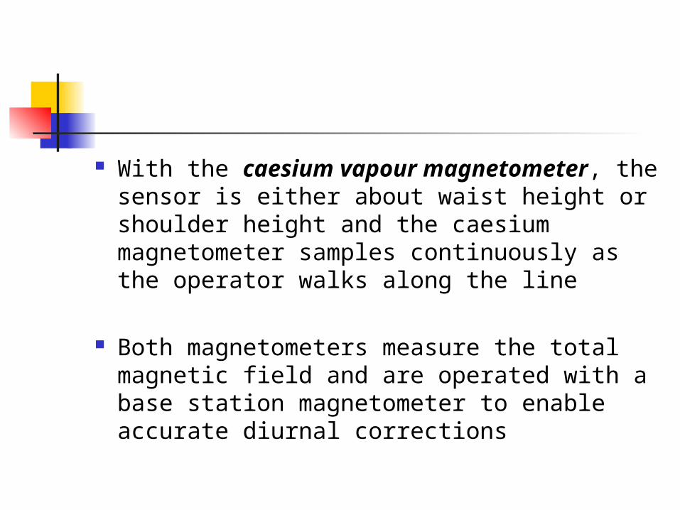
With the caesium vapour magnetometer, the sensor is either about waist height or shoulder height and the caesium magnetometer samples continuously as the operator walks along the line
Both magnetometers measure the total magnetic field and are operated with a base station magnetometer to enable accurate diurnal corrections
Magnetics: Total magnetic intensity (induction) measurements.
Units: Gammas or nanoTesla (nT)
Constraints:
Utilities, power lines, buildings, and metallic debris can cause interference. Solar magnetic storms may cause fluctuations in readings. The size and depth of objects affect detectability

Ground magnetic survey
The ground magnetic measurements were performed using walking magnetometer GSM 19TW (Proton precision magnetometer fitted
with GPS)
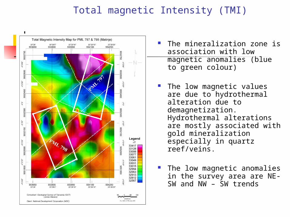
Total magnetic Intensity (TMI)
The mineralization zone is association with low magnetic anomalies (blue to green colour)
The low magnetic values are due to hydrothermal alteration due to demagnetization. Hydrothermal alterations are mostly associated with gold mineralization especially in quartz reef/veins.
The low magnetic anomalies in the survey area are NE-SW and NW – SW trends
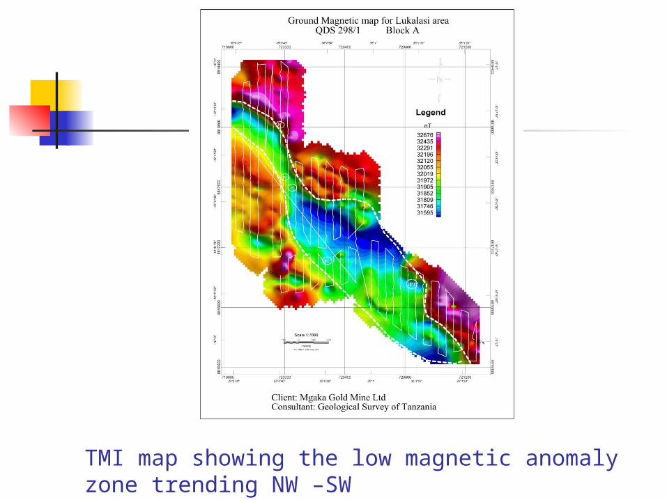
TMI map showing the low magnetic anomaly zone trending NW –SW
INDUCED POLARIZATION AND RESISTIVITY
Resistivity and induced polarization (IP) are two of the most common electrical methods.
They measure parameters associated with voltages induced in the ground by direct application of current.
Resistivity gives information on ground bulk resistivity while IP gives ground impedance or capacitance.
Recent developments include Multi Pole-Dipole and Dipole-Dipole arrays for greater resolution.
Types of array Schlumberger Wenner Dipole – Dipole Pole – DipoleExamples of arrays used for
measuring and calculating resistivity Vs depth section or profile
Units: Ohm –meters for resistivity
The depth of exploration is based on the geometry of the array
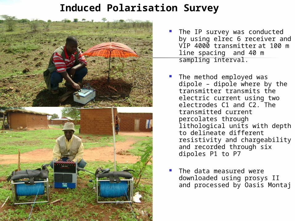
The IP survey was conducted by using elrec 6 receiver and VIP 4000 transmitter at 100 m line spacing and 40 m sampling interval.
The method employed was dipole – dipole where by the transmitter transmits the electric current using two electrodes C1 and C2. The transmitted current percolates through lithological units with depth to delineate different resistivity and chargeability and recorded through six dipoles P1 to P7
The data measured were downloaded using prosys II and processed by Oasis Montaj
Induced Polarisation Survey
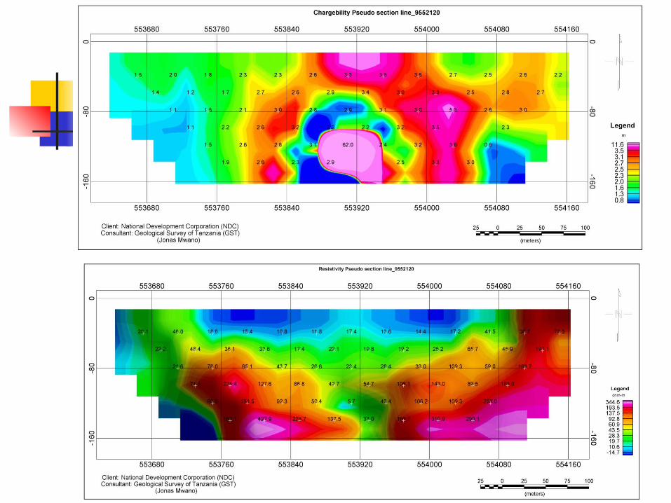
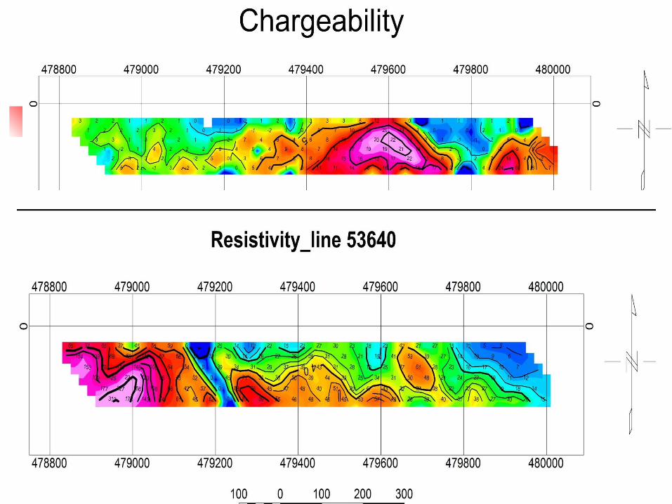
DATA PROCESSING AND PRESENTATION
Geophysicists are assigned to all field crews in order to ensure efficient field operations and to monitor data quality. In-field data products include contoured colour-image, pseudo-section profiles and contoured shaded colour image plan maps of several parameters.
Interpretation of the data is available using various computer modelling routines such as Interpex RESIXIP2DI using Zonge or Interpex algorithms and Oasis Montaj.
ADVANTAGES Ideal for detecting disseminated sulfides,
which often contain desired minerals. Resistivity and IP data can be collected
simultaneously using the same instrumentation.
Resistivity is equally effective at detecting resistive or conductive targets.
IP may be used for mineral discrimination. A multitude of configurations are available
depending on the survey target.
APPLICATIONS
Mineral exploration - detection of ore bodies by their resistivity and/or IP anomalies. Groundwater investigation - aquifers can be detected as resistivity anomalies.
Stratigraphy mapping - differing soil and/or rock types may have different inherent resistivity.
Geotechnical - soil or rock resistivity is important in many geotechnical projects.
Environmental - IP methods can assist in the assessment of the acid generating potential of waste rock and tailings from mine operations. Resistivity can be used to map contamination plumes.
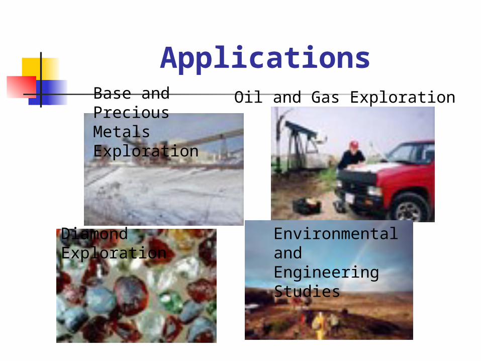
ApplicationsBase and Precious Metals Exploration
Oil and Gas Exploration
Diamond Exploration Environmental and Engineering Studies

Geothermal Exploration
Reservoir Monitoring Groundwater Exploration
Deep Crustal Research
Earthquake Prediction Research
Constraints:
I.P. cannot be done over frozen ground or asphalt because good contact with the ground is required. I.P. is affected by changes in surface relief and lateral changes in resistivity.
TIME DOMAIN ELECTROMAGNETICS
Time-Domain ElectroMagnetic (TDEM) methods are based on the principle of using electromagnetic induction to generate measurable responses from sub-surface features.
When a steady current in a cable loop is terminated a time varying magnetic field is generated. As a result of this magnetic field, eddy currents are induced in underground conductive materials.
The decay of the eddy currents in these materials is directly related to their conductive properties, and may be measured by a suitable receiver coil on the surface.
TEDM
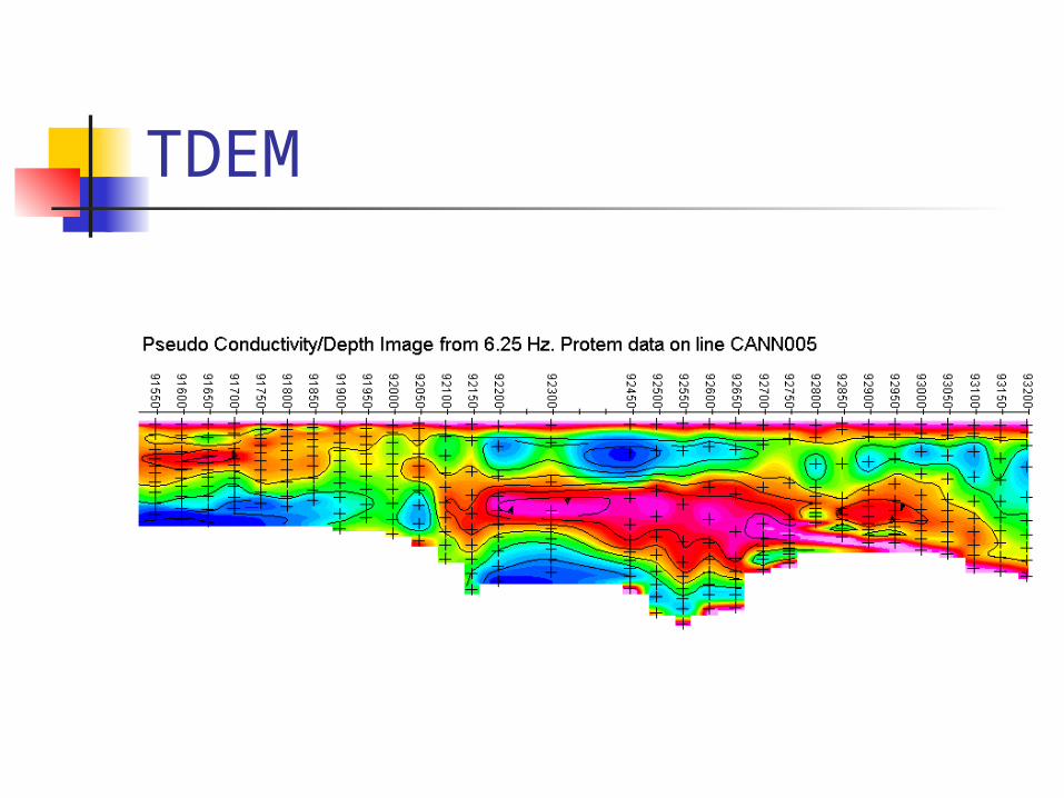
In order to identify a specific feature, it is necessary that its inherent electrical conductivity contrast significantly with the conductivity of surrounding materials.
In most successful TDEM applications, the targets sought possess enhanced conductivities relative to their host material, as demonstrated in the image below.
TDEM
APPLICATIONS Mineral exploration - metallic elements are found
in highly conductive massive sulfide ore bodies. Groundwater investigations - groundwater
contaminants such as salts and acids significantly increase the groundwater conductivity.
Stratigraphy mapping - rock types may have different conductivities.
Geothermal energy - geothermal alteration due to hot water increases the conductivity of the host rock.
Permafrost mapping - there is a significant conductivity contrast at the interface between frozen and unfrozen ground.
Environmental - locate hazards such as drums and tanks.
ADVANTAGES
TDEM systems may be used in many different configurations such as large loop Turam style, moving loop Slingram style, in-loop soundings, and borehole.
A pulsed transmitter waveform allows the receiver to measure the electromagnetic response during the transmitter off-time without the presence of the primary field.
No direct electrical contact with the ground is required so that surveys can be equally effective in frozen environments.
The same basic techniques can be used to investigate the top few metres of ground or to depths over 1000 metres.
Generally fast and cost effective for the amount of data generated.
DATA PROCESSING AND PRESENTATION
Geophysicists are assigned to all field crews in order to ensure efficient field operations and to monitor data quality.
Custom developed 32 bit data processing software is used to rigourously analyse data in the field and generate profiles. Interpretation of the data is available using various computer modeling routines such as Grendl, Beowulf and Spiker.
Depth of exploration FEM: Frequency domain electromagnetic,
the depth is controlled by frequency, earth resistivity, Tx-Rx seperation.
TEM: Transient or time domain eletromagnetic, depth of exploration is controlled by the size of transmitting loop, earth resistivity or decay time
Units: milliseconds for time decay and ohms-meter for calculated resistivities.
Constraints: Measurements are affected by
power lines, metal fences, metal debris, and utilities.
Fracture detection is affected by overburden thickness, soil conductivity, and orientation and dip of the fractures.
Gravity Gravity methods depend upon the relative density
of the ore deposit and surrounding wall rock, and are not much used in metalliferous exploration.
Measurements can only be made at fixed stations on the ground, and complicated corrections are required for station position and topographic conditions.
The typical ore deposit is not dense enough, is too small and irregular, and occurs in a deformed structural environment, making clearly defined gravity anomalies difficult to discern and interpret.
The method has been very successful in exploring for large deposits of petroleum, natural gas, sulfur, and salt. Limited application has been reported in exploration for barite.
Gravity surveys can provide useful information where other methods do not work. For example, gravity may be used to map bedrock topography under a landfill, where seismic refraction is limited. Gravity can also be used to map lateral lithologic changes, and faults.
Constraints:
Gravity surveys are relatively slow and expensive. Detectability varies with target size, depth and density contrast. Interpretation of data often requires control data from drilling, outcrops, or other sources. Detailed surface topographic survey data is also required.
Applications
bedrock topography under landfills mapping large metallic mineral
deposits locating subsurface caverns locating contacts between geologic
units of differing mass and density
Radiometric Spectrometer: mapping out natural gamma
radiation from K, Th and U
Uranium, thorium, and potassium occur naturally in earth materials, and being radioactive, anomalous concentration may be detected by radiometric surveys. Only gamma radiation is useful in exploration, because alpha and beta emissions are masked by a thin cover of soil, water, or air.
Gamma ray emissions penetrate only a few inches of soil or a few hundred feet of air, so that the radioactive ore deposit must virtually outcrop at the surface to be detected
Units: counts per seconds, ppm, electron volts (energy)
Seismic: Refraction or reflection
Seismic methods have little use in metalliferous exploration because of the relatively small size and complicated geology of the typical ore deposit, and because of the high cost of seismic work.
The method depends upon the velocities of acoustical energy in earth materials, and has been enormously successful in searching for petroleum, natural gas, and sulfur, where the large deposits may be located by simply determining attitude of the enclosing strata.
Applications Depth to water table Depth to top of indurated till Depth to bedrock Fractures zones in bedrock Bedrock contour mapping Bedrock lithologic contacts
Depth of exploration is a function of timeUnits: millisecond vs distance of
refraction/reflection
Constraints: Layer velocity (density) must increase
with depth. Layers must be of sufficient thickness to be detectable.
Data collected directly over loose fill (landfills) or in the presence of excessive cultural noise will result in sub-standard results. Single narrow fractures are too small to be detected