Embed Size (px)
Citation preview
PREPARED FOR:
Cuyamaca College
PREPARED BY:
SC Engineers, Inc. 17075 Via Del Campo | San Diego, CA 92127 P: 858.946.0333 | F: 858.946.0334 | www.scengineers.net
DATE PREPARED:
February 12, 2018
Grossmont-Cuyamaca College District Bldg. D Central Chilled Water Loop Tie-in
SPECIFICATION MANUAL CUYAMACA COLLEGE, EL CAJON, CA
Bldg. D Central Chilled Water Loop Tie-in TABLE OF CONTENTS Cuyamaca College
1
TABLE OF CONTENTS
DIVISION 1 GENERAL REQUIREMENTS
011000 SUMMARY
011400 WORK RESTRICTIONS
012500 SUBSTITUTION PROCEDURE
013300 SUBMITTAL PROCEDURES
014000 QUALITY REQUIREMENTS
015000 TEMPORARY FACILITIES AND CONTROLS
016000 PRODUCT REQUIREMENTS
017300 EXECUTION
017310 CUTTING AND PATCHING
017419 CONSTRUCTION WASTE MANAGEMENT AND DISPOSAL
017700 CLOSEOUT PROCEDURES
017823 OPERATION AND MAINTENANCE MANUALS
017839 PROJECT RECORD DOCUMENTS
017900 DEMONSTRATION AND TRAINING
DIVISION 23 MECHNAICAL
230500 HVAC GENERAL REQUIREMENTS
230501 BASIC HVAC MATERIALS AND METHODS
230516 EXPANSION FITTINGS AND LOOPS FOR HVAC PIPING
230519 METERS AND GAGES FOR HVAC PIPING
230523 GENERAL-DUTY VALVES FOR HVAC PIPING
230529 HANGERS AND SUPPORTS FOR HVAC PIPING AND EQUIPMENT
230548 VIBRATION & SESMIC CONTROLS FOR HVAC PIPING AND EQUIPMENT
Bldg. D Central Chilled Water Loop Tie-in TABLE OF CONTENTS Cuyamaca College
2
230553 IDENTIFICATION FOR HVAC
230730 HVAC PIPE INSULATION
230900 HVAC INSTRUMENTATION AND CONTROL
230993 HVAC SEQUENCE OF OPERATION
232113 HVAC HYDRONIC PIPING
232114 HVAC HYDRONIC DISTRIBUTION
DIVISION 31 EARTHWORK
311000 SITE CLEARING
312000 EARTH MOVING
DIVISION 32 EXTERIOR IMPROVEMENTS
321216 ASPHALT PAVING
321313 CONCRETE PAVING
END OF TOC
01/19/2018
Bldg. D Central Chilled Water Loop Tie-in SUMMARY Cuyamaca College 011000 - 1
SECTION 011000 - SUMMARY
PART 1 - GENERAL
1.1 RELATED DOCUMENTS
A. Drawings and general provisions of the Contract, including General and Supplementary Conditions and other Division 1 Specification Sections, apply to this Section.
1.2 WORK COVERED BY CONTRACT DOCUMENTS
A. Project Identification: The project scope includes providing a chilled water tie-in between the main central plant and Building D chiller plant and providing controls to allow Building D’s CHW plant to be served by and to serve the campus loop. The chilled water service to the campus or to the Building D must not be interrupted except for brief planned shutdowns for valve connections crossovers. 1. Project Location: 900 Rancho San Diego Parkway, El Cajon, CA. 2. Owner: Grossmont/Cuyamaca Community College District
1.3 SPECIFICATION FORMATS AND CONVENTIONS
A. Specification Format: The Specifications are organized into Divisions and Sections using CSI/CSC's "MasterFormat" numbering system.
B. Specification Content: The Specifications use certain conventions for the style of language and the intended meaning of certain terms, words, and phrases when used in particular situations. These conventions are as follows: 1. Abbreviated Language: Language used in the Specifications and other Contract
Documents is abbreviated. Words and meanings shall be interpreted as appropriate. Words implied, but not stated, shall be inferred as the sense requires. Singular words shall be interpreted as plural, and plural words shall be interpreted as singular where applicable as the context of the Contract Documents indicates.
2. Imperative mood and streamlined language are generally used in the Specifications. Requirements expressed in the imperative mood are to be performed by Contractor. Occasionally, the indicative or subjunctive mood may be used in the Section Text for clarity to describe responsibilities that must be fulfilled indirectly by Contractor or by others when so noted. a) The words "shall," "shall be," or "shall comply with," depending on the
context, are implied where a colon (:) is used within a sentence or phrase.
C. Any reference to the “Architect” in Division 01 specifications may be understood to mean the “Engineer”.
PART 2 - PRODUCTS (NOT USED)
PART 3 - EXECUTION (NO USED)
01/19/2018
Bldg. D Central Chilled Water Loop Tie-in SUMMARY Cuyamaca College 011000 - 2
END OF SECTION 011000
01/19/2018
Bldg. D Central Chilled Water Loop Tie-in WORK RESTRICTIONS Cuyamaca College 011400 - 1
SECTION 011400 - WORK RESTRICTIONS
PART 1 - GENERAL
1.1 RELATED DOCUMENTS
A. Drawings and general provisions of the Contract, including General and Supplementary Conditions and other Division 1 Specification Sections, apply to this Section.
1.2 USE OF PREMISES
A. Use of Site: Limit use of premises to work in areas indicated. Do not disturb portions of site beyond areas in which the Work is indicated. 1. Limits: Confine constructions operations to the areas indicated. 2. Owner Occupancy: Allow for Owner occupancy of site. 3. Driveways and Entrances: Keep driveways and entrances serving premises clear
and available to Owner, Owner's employees, and emergency vehicles at all times. Do not use these areas for parking or storage of materials. a) Schedule deliveries to minimize use of driveways and entrances. b) Schedule deliveries to minimize space and time requirements for storage of
materials and equipment on-site.
B. Use of Existing Building: Maintain existing building in a weather-tight condition throughout construction period. Repair damage caused by construction operations. Protect building and its occupants during construction period.
C. Maintain continuous operation of the owner’s emergency 911 and communications equipment including all supporting mechanical and electrical equipment.
1.3 OCCUPANCY REQUIREMENTS
A. Full Owner Occupancy: Owner will occupy the site and existing building during the entire construction period. Cooperate with Owner during construction operations to minimize conflicts and facilitate Owner usage. Perform the Work so as not to interfere with Owner's operations.
PART 2 - PRODUCTS (NOT USED)
PART 3 - EXECUTION (NOT USED)
END OF SECTION 011400
01/19/2018
Bldg. D Central Chilled Water Loop Tie-in SUBSTITUTION PROCEDURES Cuyamaca College 012500 - 1
SECTION 012500 - SUBSTITUTION PROCEDURES
PART 1 - GENERAL
1.1 RELATED DOCUMENTS
A. Drawings and general provisions of the Contract, including General and Supplementary Conditions and other Division 01 Specification Sections, apply to this Section.
1.2 SUMMARY
A. Section includes administrative and procedural requirements for substitutions.
B. Related Sections: 1. Division 01 Section "Product Requirements" for requirements for submitting
comparable product submittals for products by listed manufacturers.
1.3 DEFINITIONS
A. Substitutions: Changes in products, materials, equipment, and methods of construction from those required by the Contract Documents and proposed by Contractor.
1. Substitutions for Cause: Changes proposed by Contractor that are required due to changed Project conditions, such as unavailability of product, regulatory changes, or unavailability of required warranty terms.
2. Substitutions for Convenience: Changes proposed by Contractor or Owner that are not required in order to meet other Project requirements but may offer advantage to Contractor or Owner.
1.4 SUBMITTALS
A. Substitution Requests: Submit three copies of each request for consideration. Identify product or fabrication or installation method to be replaced. Include Specification Section number and title and Drawing numbers and titles.
1. Substitution Request Form: Use CSI Form 13.1A. 2. Documentation: Show compliance with requirements for substitutions and the
following, as applicable:
a. Statement indicating why specified product or fabrication or installation cannot be provided, if applicable.
01/19/2018
Bldg. D Central Chilled Water Loop Tie-in SUBSTITUTION PROCEDURES Cuyamaca College 012500 - 2
b. Coordination information, including a list of changes or modifications needed to other parts of the Work and to construction performed by Owner and separate contractors, that will be necessary to accommodate proposed substitution.
c. Detailed comparison of significant qualities of proposed substitution with those of the Work specified. Include annotated copy of applicable specification section. Significant qualities may include attributes such as performance, weight, size, durability, visual effect, sustainable design characteristics, warranties, and specific features and requirements indicated. Indicate deviations, if any, from the Work specified.
d. Product Data, including drawings and descriptions of products and fabrication and installation procedures.
e. Samples, where applicable or requested. f. Certificates and qualification data, where applicable or requested. g. List of similar installations for completed projects with project names and
addresses and names and addresses of architects and owners. h. Material test reports from a qualified testing agency indicating and
interpreting test results for compliance with requirements indicated. i. Research reports evidencing compliance with building code in effect for
Project, from ICC-ES. j. Detailed comparison of Contractor's construction schedule using proposed
substitution with products specified for the Work, including effect on the overall Contract Time. If specified product or method of construction cannot be provided within the Contract Time, include letter from manufacturer, on manufacturer's letterhead, stating date of receipt of purchase order, lack of availability, or delays in delivery.
k. Cost information, including a proposal of change, if any, in the Contract Sum.
l. Contractor's certification that proposed substitution complies with requirements in the Contract Documents except as indicated in substitution request, is compatible with related materials, and is appropriate for applications indicated.
m. Contractor's waiver of rights to additional payment or time that may subsequently become necessary because of failure of proposed substitution to produce indicated results.
3. Architect's Action: If necessary, Architect will request additional information or documentation for evaluation within fifteen days of receipt of a request for substitution. Architect will notify Contractor through Construction Manager of acceptance or rejection of proposed substitution within 21 days of receipt of request, or seven days of receipt of additional information or documentation, whichever is later.
01/19/2018
Bldg. D Central Chilled Water Loop Tie-in SUBSTITUTION PROCEDURES Cuyamaca College 012500 - 3
a. Forms of Acceptance: Change Order, Construction Change Directive, or Architect's Supplemental Instructions for minor changes in the Work.
b. Use product specified if Architect does not issue a decision on use of a proposed substitution within time allocated.
1.5 QUALITY ASSURANCE
A. Compatibility of Substitutions: Investigate and document compatibility of proposed substitution with related products and materials. Engage qualified testing agency to perform compatibility tests recommended by manufacturers.
1.6 PROCEDURES
A. Coordination: Modify or adjust affected work as necessary to integrate work of the approved substitutions.
PART 2 - PRODUCTS
2.1 SUBSTITUTIONS
A. Substitutions for Cause: Submit requests for substitution immediately upon discovery of need for change, but not later than 15 days prior to time required for preparation and review of related submittals.
1. Conditions: Architect will consider Contractor's request for substitution when the following conditions are satisfied. If the following conditions are not satisfied, Architect will return requests without action, except to record noncompliance with these requirements:
a. Requested substitution is consistent with the Contract Documents and will produce indicated results.
b. Substitution request is fully documented and properly submitted. c. Requested substitution will not adversely affect Contractor's construction
schedule. d. Requested substitution has received necessary approvals of authorities
having jurisdiction. e. Requested substitution is compatible with other portions of the Work. f. Requested substitution has been coordinated with other portions of the
Work. g. Requested substitution provides specified warranty. h. If requested substitution involves more than one contractor, requested
substitution has been coordinated with other portions of the Work, is
01/19/2018
Bldg. D Central Chilled Water Loop Tie-in SUBSTITUTION PROCEDURES Cuyamaca College 012500 - 4
uniform and consistent, is compatible with other products, and is acceptable to all contractors involved.
B. Substitutions for Convenience: Architect will consider requests for substitution if received no later than nine (9) business days prior to the bid opening.. Requests received after that time will not be considered..
1. Conditions: Architect may consider Contractor's request for substitution when the following conditions are satisfied. If the following conditions are not satisfied, Architect will return requests without action, except to record noncompliance with these requirements:
a. Requested substitution offers Owner a substantial advantage in cost, time, energy conservation, or other considerations, after deducting additional responsibilities Owner must assume. Owner's additional responsibilities may include compensation to Architect for redesign and evaluation services, increased cost of other construction by Owner, and similar considerations.
b. Requested substitution does not require extensive revisions to the Contract Documents.
c. Requested substitution is consistent with the Contract Documents and will produce indicated results.
d. Substitution request is fully documented and properly submitted. e. Requested substitution will not adversely affect Contractor's construction
schedule. f. Requested substitution has received necessary approvals of authorities
having jurisdiction. g. Requested substitution is compatible with other portions of the Work. h. Requested substitution has been coordinated with other portions of the
Work. i. Requested substitution provides specified warranty. j. If requested substitution involves more than one contractor, requested
substitution has been coordinated with other portions of the Work, is uniform and consistent, is compatible with other products, and is acceptable to all contractors involved.
PART 3 - EXECUTION (Not Used)
END OF SECTION 012500

01/19/2018
Bldg. D Central Chilled Water Loop Tie-in SUBMITTAL PROCEDURES Cuyamaca College 013300 - 1
SECTION 013300 - SUBMITTAL PROCEDURES
PART 1 - GENERAL
1.1 RELATED DOCUMENTS
A. Drawings and general provisions of the Contract, including General and Supplementary Conditions and other Division 1 Specification Sections, apply to this Section.
1.2 SUMMARY
A. This Section includes administrative and procedural requirements for submitting Shop Drawings, Product Data, Samples, and other miscellaneous submittals.
B. Related Sections include the following: 1. Division 1 Section "Quality Requirements" for submitting test and inspection
reports and Delegated-Design Submittals. 2. Division 1 Section "Closeout Procedures" for submitting warranties Project
Record Documents and operation and maintenance manuals. 3. Division 1 Section "Operation and Maintenance Data" for operation and
maintenance manual requirements.
1.3 DEFINITIONS
A. Action Submittals: Written and graphic information that requires Engineer’s responsive action.
B. Informational Submittals: Written information that does not require Engineer’s approval. Submittals may be rejected for not complying with requirements.
1.4 SUBMITTAL PROCEDURES
A. General: Electronic copies of CAD Drawings of the Contract Drawings will be provided by Engineer for Contractor's use in preparing submittals.
B. Coordination: Coordinate preparation and processing of submittals with performance of construction activities. 1. Coordinate each submittal with fabrication, purchasing, testing, delivery, other
submittals, and related activities that require sequential activity. 2. Coordinate transmittal of different types of submittals for related parts of the
Work so processing will not be delayed because of need to review submittals concurrently for coordination. a) Engineer reserves the right to withhold action on a submittal requiring
coordination with other submittals until related submittals are received.
C. Processing Time: Allow enough time for submittal review, including time for resubmittals, as follows. Time for review shall commence on Engineer’s receipt of submittal.
01/19/2018
Bldg. D Central Chilled Water Loop Tie-in SUBMITTAL PROCEDURES Cuyamaca College 013300 - 2
1. Initial Review: Allow 15 days for initial review of each submittal. Allow additional time if processing must be delayed to permit coordination with subsequent submittals. Engineer will advise Contractor when a submittal being processed must be delayed for coordination.
2. Concurrent Review: Where concurrent review of submittals by Engineer’s consultants, Owner, or other parties is required, allow 21 days for initial review of each submittal.
3. If intermediate submittal is necessary, process it in same manner as initial submittal.
4. Allow 15 days for processing each resubmittal. 5. No extension of the Contract Time will be authorized because of failure to
transmit submittals enough in advance of the Work to permit processing.
D. Identification: Place a permanent label or title block on each submittal for identification. 1. Indicate name of firm or entity that prepared each submittal on label or title
block. 2. Provide a space approximately 4 by 5 inches on label or beside title block to
record Contractor's review and approval markings and action taken by Engineer. 3. Include the following information on label for processing and recording action
taken: a) Project name. b) Date. c) Name and address of Engineer. d) Name and address of Contractor. e) Name and address of subcontractor. f) Name and address of supplier. g) Name of manufacturer. h) Unique identifier, including revision number. i) Number and title of appropriate Specification Section. j) Drawing number and detail references, as appropriate. k) Other necessary identification.
E. Deviations: Highlight, encircle, or otherwise identify deviations from the Contract Documents on submittals. All proposed deviations shall be submitted separately from the product submittals.
F. Additional Copies: Unless additional copies are required for final submittal, and unless Engineer observes noncompliance with provisions of the Contract Documents, initial submittal may serve as final submittal.
G. Transmittal: Package each submittal individually and appropriately for transmittal and handling. Transmit each submittal using a transmittal form. Engineer will discard submittals received from sources other than Contractor. 1. On an attached separate sheet, prepared on Contractor's letterhead, record
relevant information, requests for data, revisions other than those requested by Engineer on previous submittals, and deviations from requirements of the
01/19/2018
Bldg. D Central Chilled Water Loop Tie-in SUBMITTAL PROCEDURES Cuyamaca College 013300 - 3
Contract Documents, including minor variations and limitations. Include the same label information as the related submittal.
2. Include Contractor's certification stating that information submitted complies with requirements of the Contract Documents.
3. Transmittal Form: Provide locations on form for the following information: a) Project name. b) Date. c) Destination (To:). d) Source (From:). e) Names of subcontractor, manufacturer, and supplier. f) Category and type of submittal. g) Submittal purpose and description. h) Submittal and transmittal distribution record. i) Remarks. j) Signature of transmitter.
H. Distribution: Furnish copies of final submittals to manufacturers, subcontractors, suppliers, fabricators, installers, authorities having jurisdiction, and others as necessary for performance of construction activities. Show distribution on transmittal forms.
I. Use for Construction: Use only final submittals with mark indicating action taken by Engineer in connection with construction.
J. Electronic submittals via email are encouraged. All requirements except the number of copies apply to electronic submittals.
PART 2 - PRODUCTS
2.1 ACTION SUBMITTALS
A. General: Prepare and submit Action Submittals required by individual Specification Sections. 1. Number of Copies: Submit four copies of each submittal, unless otherwise
indicated. Engineer will return two copies. Mark up and retain one returned copy as a Project Record Document.
B. Product Data: Collect information into a single submittal for each specification section. Include each element of construction and type of product or equipment. 1. If information must be specially prepared for submittal because standard printed
data are not suitable for use, submit as Shop Drawings, not as Product Data. 2. Mark each copy of each submittal to show which products and options are
applicable. 3. Include the following information, as applicable:
a) Manufacturer's written recommendations. b) Manufacturer's product specifications. c) Manufacturer's installation instructions. d) Standard color charts.

01/19/2018
Bldg. D Central Chilled Water Loop Tie-in SUBMITTAL PROCEDURES Cuyamaca College 013300 - 4
e) Manufacturer's catalog cuts. f) Wiring diagrams showing factory-installed wiring. g) Printed performance curves. h) Operational range diagrams. i) Mill reports. j) Standard product operating and maintenance manuals. k) Compliance with recognized trade association standards. l) Compliance with recognized testing agency standards. m) Application of testing agency labels and seals. n) Notation of coordination requirements.
C. Shop Drawings: Prepare Project-specific information, drawn accurately to scale. Do not base Shop Drawings on reproductions of the Contract Documents or standard printed data. 2D shop drawings (minimum ¼”=1’0” scale) shall be submitted for review. 1. Preparation: Include the following information, as applicable:
a) Dimensions. b) Identification of products. c) Fabrication and installation drawings. d) Roughing-in and setting diagrams. e) Wiring diagrams showing field-installed wiring, including power, signal, and
control wiring. f) Shopwork manufacturing instructions. g) Templates and patterns. h) Schedules. i) Design calculations. j) Compliance with specified standards. k) Notation of coordination requirements. l) Notation of dimensions established by field measurement.
2. Wiring Diagrams: Differentiate between manufacturer-installed and field-installed wiring.
3. Sheet Size: Except for templates, patterns, and similar full-size drawings, submit Shop Drawings on sheets at least 8-1/2 by 11 inches but no larger than 22 by 34 inches. Submit electronic copies to the engineer.
4. Number of Copies: Submit one correctable, translucent, reproducible print and one blue- or black-line print of each submittal. Engineer will return the reproducible print.
5. Number of Copies: Submit three blue- or black-line prints of each submittal, unless prints are required for operation and maintenance manuals. Submit five prints where prints are required for operation and maintenance manuals. Engineer will retain two prints; remainder will be returned. Mark up and retain one returned print as a Project Record Drawing.
6. Number of Copies: Submit one correctable, translucent, reproducible print and one blue- or black-line print. Engineer, will return the reproducible print.
01/19/2018
Bldg. D Central Chilled Water Loop Tie-in SUBMITTAL PROCEDURES Cuyamaca College 013300 - 5
D. Product Schedule or List: Prepare a written summary indicating types of products required for the Work and their intended location. Include the following information in tabular form: 1. Type of product. Include unique identifier for each product. 2. Number and name of room or space. 3. Location within room or space.
E. Delegated-Design Submittal: Comply with requirements in Division 1 Section "Quality Requirements."
F. Submittals Schedule: Provide a submittal schedule indicating all submittals required an the status of each.
2.2 INFORMATIONAL SUBMITTALS
A. General: Prepare and submit Informational Submittals required by other Specification Sections. 1. Number of Copies: Submit two copies of each submittal, unless otherwise
indicated. Engineer will not return copies. 2. Certificates and Certifications: Provide a notarized statement that includes
signature of entity responsible for preparing certification. Certificates and certifications shall be signed by an officer or other individual authorized to sign documents on behalf of that entity.
3. Test and Inspection Reports: Comply with requirements in Division 1 Section "Quality Requirements."
B. Product Certificates: Prepare written statements on manufacturer's letterhead certifying that product complies with requirements.
C. Welding Certificates: Prepare written certification that welding procedures and personnel comply with requirements. Submit record of Welding Procedure Specification (WPS) and Procedure Qualification Record (PQR) on AWS forms. Include names of firms and personnel certified.
D. Installer Certificates: Prepare written statements on manufacturer's letterhead certifying that Installer complies with requirements and, where required, is authorized for this specific Project.
E. Manufacturer Certificates: Prepare written statements on manufacturer's letterhead certifying that manufacturer complies with requirements. Include evidence of manufacturing experience where required.
F. Material Certificates: Prepare written statements on manufacturer's letterhead certifying that material complies with requirements.
G. Material Test Reports: Prepare reports written by a qualified testing agency, on testing agency's standard form, indicating and interpreting test results of material for compliance with requirements.
01/19/2018
Bldg. D Central Chilled Water Loop Tie-in SUBMITTAL PROCEDURES Cuyamaca College 013300 - 6
H. Preconstruction Test Reports: Prepare reports written by a qualified testing agency, on testing agency's standard form, indicating and interpreting results of tests performed before installation of product, for compliance with performance requirements.
I. Compatibility Test Reports: Prepare reports written by a qualified testing agency, on testing agency's standard form, indicating and interpreting results of compatibility tests performed before installation of product. Include written recommendations for primers and substrate preparation needed for adhesion.
J. Field Test Reports: Prepare reports written by a qualified testing agency, on testing agency's standard form, indicating and interpreting results of field tests performed either during installation of product or after product is installed in its final location, for compliance with requirements.
K. Product Test Reports: Prepare written reports indicating current product produced by manufacturer complies with requirements. Base reports on evaluation of tests performed by manufacturer and witnessed by a qualified testing agency, or on comprehensive tests performed by a qualified testing agency.
L. Research/Evaluation Reports: Prepare written evidence, from a model code organization acceptable to authorities having jurisdiction, that product complies with building code in effect for Project. Include the following information: 1. Name of evaluation organization. 2. Date of evaluation. 3. Time period when report is in effect. 4. Product and manufacturers' names. 5. Description of product. 6. Test procedures and results. 7. Limitations of use.
M. Maintenance Data: Prepare written and graphic instructions and procedures for operation and normal maintenance of products and equipment. Comply with requirements in Division 1 Section "Closeout Procedures."
N. Design Data: Prepare written and graphic information, including, but not limited to, performance and design criteria, list of applicable codes and regulations, and calculations. Include list of assumptions and other performance and design criteria and a summary of loads. Include load diagrams if applicable. Provide name and version of software, if any, used for calculations. Include page numbers.
O. Manufacturer's Instructions: Prepare written or published information that documents manufacturer's recommendations, guidelines, and procedures for installing or operating a product or equipment. Include name of product and name, address, and telephone number of manufacturer. Include the following, as applicable: 1. Preparation of substrates. 2. Required substrate tolerances. 3. Sequence of installation or erection.
01/19/2018
Bldg. D Central Chilled Water Loop Tie-in SUBMITTAL PROCEDURES Cuyamaca College 013300 - 7
4. Required installation tolerances. 5. Required adjustments. 6. Recommendations for cleaning and protection.
P. Manufacturer's Field Reports: Prepare written information documenting factory-authorized service representative's tests and inspections. Include the following, as applicable: 1. Name, address, and telephone number of factory-authorized service
representative making report. 2. Statement on condition of substrates and their acceptability for installation of
product. 3. Statement that products at Project site comply with requirements. 4. Summary of installation procedures being followed, whether they comply with
requirements and, if not, what corrective action was taken. 5. Results of operational and other tests and a statement of whether observed
performance complies with requirements. 6. Statement whether conditions, products, and installation will affect warranty. 7. Other required items indicated in individual Specification Sections.
Q. Insurance Certificates and Bonds: Prepare written information indicating current status of insurance or bonding coverage. Include name of entity covered by insurance or bond, limits of coverage, amounts of deductibles, if any, and term of the coverage.
R. Material Safety Data Sheets: Submit information directly to Owner. If submitted to Architect, Architect will not review this information but will return it with no action taken.
PART 3 - EXECUTION
3.1 CONTRACTOR'S REVIEW
A. Review each submittal and check for compliance with the Contract Documents. Note corrections and field dimensions. Mark with approval stamp before submitting to Engineer.
B. Approval Stamp: Stamp each submittal with a uniform, approval stamp. Include Project name and location, submittal number, Specification Section title and number, name of reviewer, date of Contractor's approval, and statement certifying that submittal has been reviewed, checked, and approved for compliance with the Contract Documents.
3.2 ENGINEER’S ACTION
A. General: Engineer will not review submittals that do not bear Contractor's approval stamp and will return them without action.
01/19/2018
Bldg. D Central Chilled Water Loop Tie-in SUBMITTAL PROCEDURES Cuyamaca College 013300 - 8
B. Action Submittals: Engineer will review each submittal, make marks to indicate corrections or modifications required, and return it. Engineer will stamp each submittal with an action stamp and will mark stamp appropriately to indicate action taken.
C. Informational Submittals: Engineer will review each submittal and will not return it, or will reject and return it if it does not comply with requirements. Engineer will forward each submittal to appropriate party.
D. Submittals not required by the Contract Documents will not be reviewed and may be discarded.
END OF SECTION 013300
01/19/2018
Bldg. D Central Chilled Water Loop Tie-in QUALITY REQUIREMENTS Cuyamaca College 014000 - 1
SECTION 014000 - QUALITY REQUIREMENTS
PART 1 - GENERAL
1.1 RELATED DOCUMENTS
A. Drawings and general provisions of the Contract, including General and Supplementary Conditions and other Division 1 Specification Sections, apply to this Section.
1.2 SUMMARY
A. This Section includes administrative and procedural requirements for quality assurance and quality control.
B. Testing and inspecting services are required to verify compliance with requirements specified or indicated. These services do not relieve Contractor of responsibility for compliance with the Contract Document requirements. 1. Specific quality-control requirements for individual construction activities are
specified in the Sections that specify those activities. Requirements in those Sections may also cover production of standard products.
2. Specified tests, inspections, and related actions do not limit Contractor's quality-control procedures that facilitate compliance with the Contract Document requirements.
3. Requirements for Contractor to provide quality-control services required by Engineer, or authorities having jurisdiction are not limited by provisions of this Section.
C. Related Sections include the following: 1. Division 1 Section "Cutting and Patching" for repair and restoration of
construction disturbed by testing and inspecting activities. 2. Divisions 23 Sections for specific test and inspection requirements.
1.3 DEFINITIONS
A. Quality-Assurance Services: Activities, actions, and procedures performed before and during execution of the Work to guard against defects and deficiencies and ensure that proposed construction complies with requirements.
B. Quality-Control Services: Tests, inspections, procedures, and related actions during and after execution of the Work to evaluate that completed construction complies with requirements. Services do not include contract enforcement activities performed by Engineer.
C. Testing Agency: An entity engaged to perform specific tests, inspections, or both. Testing laboratory shall mean the same as testing agency.
1.4 DELEGATED DESIGN

01/19/2018
Bldg. D Central Chilled Water Loop Tie-in QUALITY REQUIREMENTS Cuyamaca College 014000 - 2
A. Performance and Design Criteria: Where professional design services or certifications by a design professional are specifically required of Contractor by the Contract Documents, provide products and systems complying with specific performance and design criteria indicated. 1. If criteria indicated are not sufficient to perform services or certification required,
submit a written request for additional information to Engineer.
1.5 SUBMITTALS
A. Qualification Data: For testing agencies specified in "Quality Assurance" Article to demonstrate their capabilities and experience. Include proof of qualifications in the form of a recent report on the inspection of the testing agency by a recognized authority.
B. Delegated-Design Submittal: In addition to Shop Drawings, Product Data, and other required submittals, submit a statement, signed and sealed by the responsible design professional, for each product and system specifically assigned to Contractor to be designed or certified by a design professional, indicating that the products and systems are in compliance with performance and design criteria indicated. Include list of codes, loads, and other factors used in performing these services.
C. Schedule of Tests and Inspections: Prepare in tabular form and include the following: 1. Specification Section number and title. 2. Description of test and inspection. 3. Identification of applicable standards. 4. Identification of test and inspection methods. 5. Number of tests and inspections required. 6. Time schedule or time span for tests and inspections. 7. Entity responsible for performing tests and inspections.
D. Reports: Prepare and submit certified written reports that include the following: 1. Date of issue. 2. Project title and number. 3. Name, address, and telephone number of testing agency. 4. Dates and locations of samples and tests or inspections. 5. Names of individuals making tests and inspections. 6. Description of the Work and test and inspection method. 7. Identification of product and Specification Section. 8. Complete test or inspection data. 9. Test and inspection results and an interpretation of test results. 10. Comments or professional opinion on whether tested or inspected Work
complies with the Contract Document requirements. 11. Name and signature of laboratory inspector. 12. Recommendations on retesting and reinspecting.
E. Permits, Licenses, and Certificates: For Owner's records, submit copies of permits, licenses, certifications, inspection reports, releases, jurisdictional settlements, notices,
01/19/2018
Bldg. D Central Chilled Water Loop Tie-in QUALITY REQUIREMENTS Cuyamaca College 014000 - 3
receipts for fee payments, judgments, correspondence, records, and similar documents, established for compliance with standards and regulations bearing on performance of the Work.
1.6 QUALITY ASSURANCE
A. Fabricator Qualifications: A firm experienced in producing products similar to those indicated for this Project and with a record of successful in-service performance, as well as sufficient production capacity to produce required units.
B. Factory-Authorized Service Representative Qualifications: An authorized representative of manufacturer who is trained and approved by manufacturer to inspect installation of manufacturer's products that are similar in material, design, and extent to those indicated for this Project.
C. Installer Qualifications: A firm or individual experienced in installing, erecting, or assembling work similar in material, design, and extent to that indicated for this Project, whose work has resulted in construction with a record of successful in-service performance.
D. Manufacturer Qualifications: A firm experienced in manufacturing products or systems similar to those indicated for this Project and with a record of successful in-service performance.
E. Professional Engineer Qualifications: A professional engineer who is legally qualified to practice in jurisdiction where Project is located and who is experienced in providing engineering services of the kind indicated. Engineering services are defined as those performed for installations of the system, assembly, or product that are similar to those indicated for this Project in material, design, and extent.
F. Testing Agency Qualifications: An agency with the experience and capability to conduct testing and inspecting indicated, as documented by ASTM E 548, and that specializes in types of tests and inspections to be performed.
1.7 QUALITY CONTROL
A. Contractor Responsibilities: Unless otherwise indicated, provide quality-control services specified and required by authorities having jurisdiction. 1. Where services are indicated as Contractor's responsibility, engage a qualified
testing agency to perform these quality-control services. a) Contractor shall not employ the same entity engaged by Owner, unless
agreed to in writing by Owner. 2. Notify testing agencies at least 24 hours in advance of time when Work that
requires testing or inspecting will be performed. 3. Where quality-control services are indicated as Contractor's responsibility, submit
a certified written report, in duplicate, of each quality-control service. 4. Testing and inspecting requested by Contractor and not required by the Contract
Documents are Contractor's responsibility.

01/19/2018
Bldg. D Central Chilled Water Loop Tie-in QUALITY REQUIREMENTS Cuyamaca College 014000 - 4
5. Submit additional copies of each written report directly to authorities having jurisdiction, when they so direct.
B. Manufacturer's Field Services: Where indicated, engage a factory-authorized service representative to inspect field-assembled components and equipment installation, including service connections. Report results in writing.
C. Retesting/Reinspecting: Regardless of whether original tests or inspections were Contractor's responsibility, provide quality-control services, including retesting and reinspecting, for construction that revised or replaced Work that failed to comply with requirements established by the Contract Documents.
D. Testing Agency Responsibilities: Cooperate with Engineer and Contractor in performance of duties. Provide qualified personnel to perform required tests and inspections. 1. Notify Engineer and Contractor promptly of irregularities or deficiencies observed
in the Work during performance of its services. 2. Interpret tests and inspections and state in each report whether tested and
inspected work complies with or deviates from requirements. 3. Submit a certified written report, in duplicate, of each test, inspection, and similar
quality-control service through Contractor. 4. Do not release, revoke, alter, or increase requirements of the Contract Documents
or approve or accept any portion of the Work. 5. Do not perform any duties of Contractor.
E. Associated Services: Cooperate with agencies performing required tests, inspections, and similar quality-control services, and provide reasonable auxiliary services as requested. Notify agency sufficiently in advance of operations to permit assignment of personnel. Provide the following: 1. Access to the Work. 2. Incidental labor and facilities necessary to facilitate tests and inspections. 3. Adequate quantities of representative samples of materials that require testing
and inspecting. Assist agency in obtaining samples. 4. Facilities for storage and field-curing of test samples. 5. Delivery of samples to testing agencies. 6. Preliminary design mix proposed for use for material mixes that require control
by testing agency. 7. Security and protection for samples and for testing and inspecting equipment at
Project site.
F. Coordination: Coordinate sequence of activities to accommodate required quality-assurance and quality-control services with a minimum of delay and to avoid necessity of removing and replacing construction to accommodate testing and inspecting. 1. Schedule times for tests, inspections, obtaining samples, and similar activities.
01/19/2018
Bldg. D Central Chilled Water Loop Tie-in QUALITY REQUIREMENTS Cuyamaca College 014000 - 5
G. Schedule of Tests and Inspections: Prepare a schedule of tests, inspections, and similar quality-control services required by the Contract Documents. Submit schedule within 15 days of date established for the Notice to Proceed. 1. Distribution: Distribute schedule to Owner, Engineer, testing agencies, and each
party involved in performance of portions of the Work where tests and inspections are required.
PART 2 - PRODUCTS (Not Used)
PART 3 - EXECUTION
3.1 REPAIR AND PROTECTION
A. General: On completion of testing, inspecting, sample taking, and similar services, repair damaged construction and restore substrates and finishes. 1. Provide materials and comply with installation requirements specified in other
Sections of these Specifications. Restore patched areas and extend restoration into adjoining areas in a manner that eliminates evidence of patching.
2. Comply with the Contract Document requirements for Division 1 Section "Cutting and Patching."
B. Protect construction exposed by or for quality-control service activities.
C. Repair and protection are Contractor's responsibility, regardless of the assignment of responsibility for quality-control services.
END OF SECTION 014000

01/19/2018
Bldg. D Central Chilled Water Loop Tie-in TEMPORARY FACILITIES AND CONTROLS Cuyamaca College 015000 - 1
SECTION 015000 - TEMPORARY FACILITIES AND CONTROLS
PART 1 – GENERAL
1.1 RELATED DOCUMENTS
A. Drawings and general provisions of the Contract, including General and Supplementary Conditions and other Division 1 Specification Sections, apply to this Section.
1.2 SUMMARY
A. This Section includes requirements for temporary facilities and controls, including temporary utilities, support facilities, and security and protection facilities.
B. Temporary utilities include, but are not limited to, the following: 1. Sanitary facilities, including toilets, wash facilities, and drinking-water facilities. 2. Heating and cooling facilities. 3. Electric power service. 4. Telephone service.
C. Support facilities include, but are not limited to, the following: 1. Project identification and temporary signs. 2. Waste disposal facilities. 3. Storage and fabrication sheds. 4. Construction aids and miscellaneous services and facilities.
D. Security and protection facilities include, but are not limited to, the following: 1. Environmental protection. 2. Stormwater control. 3. Tree and plant protection. 4. Security enclosure and lockup. 5. Barricades, warning signs, and lights. 6. Temporary enclosures. 7. Temporary partitions. 8. Fire protection.
E. Related Sections include the following: 1. Division 1 Section "Submittal Procedures" for procedures for submitting copies of
implementation and termination schedule and utility reports.
1.3 USE CHARGES
A. General: Cost or use charges for temporary facilities are not chargeable to Owner or Engineer and shall be included in the Contract Sum. Allow other entities to use temporary services and facilities without cost, including, but not limited to, the following: 1. Owner's construction forces. 2. Occupants of Project.
01/19/2018
Bldg. D Central Chilled Water Loop Tie-in TEMPORARY FACILITIES AND CONTROLS Cuyamaca College 015000 - 2
3. Engineers. 4. Testing agencies. 5. Personnel of authorities having jurisdiction.
B. Water Service: Use water from Owner's existing water system without metering and without payment of use charges.
C. Electric Power Service: Use electric power from Owner's existing system without metering and without payment of use charges.
1.4 SUBMITTALS
A. Temporary Utility Reports: Submit reports of tests, inspections, meter readings, and similar procedures performed on temporary utilities.
1.5 QUALITY ASSURANCE
A. Standards: Comply with ANSI A10.6, NECA's "Temporary Electrical Facilities," and NFPA 241. 1. Trade Jurisdictions: Assigned responsibilities for installation and operation of
temporary utilities are not intended to interfere with trade regulations and union jurisdictions.
2. Electric Service: Comply with NECA, NEMA, and UL standards and regulations for temporary electric service. Install service to comply with NFPA 70.
B. Tests and Inspections: Arrange for authorities having jurisdiction to test and inspect each temporary utility before use. Obtain required certifications and permits.
1.6 PROJECT CONDITIONS
A. Temporary Utilities: At earliest feasible time, when acceptable to Owner, change over from use of temporary service to use of permanent service. 1. Temporary Use of Permanent Facilities: Installer of each permanent service shall
assume responsibility for operation, maintenance, and protection of each permanent service during its use as a construction facility before Owner's acceptance, regardless of previously assigned responsibilities.
B. Conditions of Use: The following conditions apply to use of temporary services and facilities by all parties engaged in the Work: 1. Keep temporary services and facilities clean and neat. 2. Relocate temporary services and facilities as required by progress of the Work.
PART 2 - PRODUCTS
2.1 MATERIALS
01/19/2018
Bldg. D Central Chilled Water Loop Tie-in TEMPORARY FACILITIES AND CONTROLS Cuyamaca College 015000 - 3
A. General: Provide new materials. Undamaged, previously used materials in serviceable condition may be used if approved by Architect. Provide materials suitable for use intended.
B. Chain-Link Fencing: Minimum 2-inch, 0.148-inch- thick, galvanized steel, chain-link fabric fencing; minimum 6 feet high with galvanized steel pipe posts; minimum 2-3/8-inch- OD line posts and 2-7/8-inch- OD corner and pull posts.
C. Tarpaulins: Fire-resistive labeled with flame-spread rating of 15 or less.
D. Water: Potable.
2.2 EQUIPMENT
A. General: Provide equipment suitable for use intended.
B. Fire Extinguishers: Hand carried, portable, UL rated. Provide class and extinguishing agent as indicated or a combination of extinguishers of NFPA-recommended classes for exposures. 1. Comply with NFPA 10 and NFPA 241 for classification, extinguishing agent, and
size required by location and class of fire exposure.
C. Self-Contained Toilet Units: Single-occupant units of chemical, aerated recirculation, or combustion type; vented; fully enclosed with a glass-fiber-reinforced polyester shell or similar nonabsorbent material.
D. Drinking-Water Fixtures: Containerized, tap-dispenser, bottled-water drinking-water units, including paper cup supply.
E. Heating Equipment: Provide self-contained heating units with individual space thermostatic control for heating all classrooms and offices during instruction periods.
F. Electrical Outlets: Properly configured, NEMA-polarized outlets to prevent insertion of 110- to 120-V plugs into higher-voltage outlets; equipped with ground-fault circuit interrupters, reset button, and pilot light.
PART 3 - EXECUTION
3.1 INSTALLATION, GENERAL
A. Locate facilities where they will serve Project adequately and result in minimum interference with performance of the Work. Relocate and modify facilities as required.
B. Provide each facility ready for use when needed to avoid delay. Maintain and modify as required. Do not remove until facilities are no longer needed or are replaced by authorized use of completed permanent facilities.
3.2 TEMPORARY UTILITY INSTALLATION
01/19/2018
Bldg. D Central Chilled Water Loop Tie-in TEMPORARY FACILITIES AND CONTROLS Cuyamaca College 015000 - 4
A. General: Engage appropriate local utility company to install temporary service or connect to existing service. Where utility company provides only part of the service, provide the remainder with matching, compatible materials and equipment. Comply with utility company recommendations. 1. Arrange with utility company, Owner, and existing users for time when service can
be interrupted, if necessary, to make connections for temporary services. 2. Provide adequate capacity at each stage of construction. Before temporary utility
is available, provide trucked-in services. 3. Obtain easements to bring temporary utilities to Project site where Owner's
easements cannot be used for that purpose.
B. Water Service: Use of Owner's existing water service facilities will be permitted, as long as facilities are cleaned and maintained in a condition acceptable to Owner. At Substantial Completion, restore these facilities to condition existing before initial use.
C. Electric Power Service: Use of Owner's existing electric power service will be permitted, as long as equipment is maintained in a condition acceptable to Owner.
D. Electric Distribution: Provide receptacle outlets adequate for connection of power tools and equipment. 1. Provide waterproof connectors to connect separate lengths of electrical power
cords if single lengths will not reach areas where construction activities are in progress. Do not exceed safe length-voltage ratio.
3.3 SUPPORT FACILITIES INSTALLATION
A. General: Comply with the following: 1. Locate storage sheds, sanitary facilities, and other temporary construction and
support facilities for easy access. 2. Provide incombustible construction for items located within construction area or
within 30 feet of building lines. Comply with NFPA 241. 3. Maintain support facilities until near Substantial Completion. Remove before
Substantial Completion. Personnel remaining after Substantial Completion will be permitted to use permanent facilities, under conditions acceptable to Owner.
B. Project Identification and Temporary Signs: Install signs where required to inform public and persons seeking entrance to Project. Do not permit installation of unauthorized signs.
C. Waste Disposal Facilities: Provide waste-collection containers in sizes adequate to handle waste from construction operations. Containerize and clearly label hazardous, dangerous, or unsanitary waste materials separately from other waste. Comply with Division 1 Section "Execution Requirements" for progress cleaning requirements.
D. Storage and Fabrication Sheds: Provide sheds sized, furnished, and equipped to accommodate materials and equipment involved, including temporary utility services.
01/19/2018
Bldg. D Central Chilled Water Loop Tie-in TEMPORARY FACILITIES AND CONTROLS Cuyamaca College 015000 - 5
Sheds may be open shelters or fully enclosed spaces within building or elsewhere on-site.
3.4 SECURITY AND PROTECTION FACILITIES INSTALLATION
A. Environmental Protection: Provide protection, operate temporary facilities, and conduct construction in ways and by methods that comply with environmental regulations and that minimize possible air, waterway, and subsoil contamination or pollution or other undesirable effects. Avoid using tools and equipment that produce harmful noise. Restrict use of noisemaking tools and equipment to hours that will minimize complaints from persons or firms near Project site.
B. Stormwater Control: Provide earthen embankments and similar barriers in and around excavations and subgrade construction, sufficient to prevent flooding by runoff of stormwater from heavy rains.
C. Tree and Plant Protection: Install temporary fencing located as indicated or outside the drip line of trees to protect vegetation from construction damage. Protect tree root systems from damage, flooding, and erosion.
D. Barricades, Warning Signs, and Lights: Comply with standards and code requirements for erecting structurally adequate barricades. Paint with appropriate colors, graphics, and warning signs to inform personnel and public of possible hazard. Where appropriate and needed, provide lighting, including flashing red or amber lights. 1. For safety barriers, sidewalk bridges, and similar uses, provide minimum 5/8-inch-
thick exterior plywood.
E. Temporary Enclosures: Provide temporary enclosures for protection of construction, in progress and completed, from exposure, foul weather, other construction operations, and similar activities. Provide temporary weathertight enclosure for building exterior.
F. Temporary Partitions: Erect and maintain dustproof partitions and temporary enclosures to limit dust and dirt migration and to separate areas from fumes and noise. 1. Construct dustproof, floor-to-ceiling partitions of not less than nominal 4-inch
studs, 2 layers of 3-mil polyethylene sheets, inside and outside temporary enclosure. Cover floor with 2 layers of 3-mil polyethylene sheets, extending sheets 18 inches up the side walls. Overlap and tape full length of joints. Cover floor with 3/4-inch fire-retardant plywood.
2. Insulate partitions to provide noise protection to occupied areas. 3. Seal joints and perimeter. Equip partitions with dustproof doors and security
locks. 4. Protect air-handling equipment. 5. Weatherstrip openings.
G. Temporary Fire Protection: Until fire-protection needs are supplied by permanent facilities, install and maintain temporary fire-protection facilities of types needed to
01/19/2018
Bldg. D Central Chilled Water Loop Tie-in TEMPORARY FACILITIES AND CONTROLS Cuyamaca College 015000 - 6
protect against reasonably predictable and controllable fire losses. Comply with NFPA 241. 1. Store combustible materials in containers in fire-safe locations. 2. Maintain unobstructed access to fire extinguishers, fire hydrants, temporary fire-
protection facilities, stairways, and other access routes for firefighting. Prohibit smoking in hazardous fire-exposure areas.
3. Supervise welding operations, combustion-type temporary heating units, and similar sources of fire ignition.
4. Permanent Fire Protection: At earliest feasible date in each area of Project, complete installation of permanent fire-protection facility, including connected services, and place into operation and use. Instruct key personnel on use of facilities.
5. Develop and supervise an overall fire-prevention and first-aid fire-protection program for personnel at Project site. Review needs with local fire department and establish procedures to be followed. Instruct personnel in methods and procedures. Post warnings and information.
3.5 OPERATION, TERMINATION, AND REMOVAL
A. Supervision: Enforce strict discipline in use of temporary facilities. To minimize waste and abuse, limit availability of temporary facilities to essential and intended uses.
B. Maintenance: Maintain facilities in good operating condition until removal. Protect from damage caused by freezing temperatures and similar elements. 1. Maintain operation of temporary enclosures, heating and cooling, and similar
facilities on a 24-hour basis where required to achieve indicated results and to avoid possibility of damage.
2. Prevent water-filled piping from freezing. Maintain markers for underground lines. Protect from damage during excavation operations.
C. Temporary Facility Changeover: Except for using permanent fire protection as soon as available, do not change over from using temporary security and protection facilities to permanent facilities until Substantial Completion.
D. Termination and Removal: Remove each temporary facility when need for its service has ended, when it has been replaced by authorized use of a permanent facility, or no later than Substantial Completion. Complete or, if necessary, restore permanent construction that may have been delayed because of interference with temporary facility. Repair damaged Work, clean exposed surfaces, and replace construction that cannot be satisfactorily repaired. 1. Materials and facilities that constitute temporary facilities are the property of
Contractor. Owner reserves right to take possession of Project identification signs.
2. At Substantial Completion, clean and renovate permanent facilities used during construction period. Comply with final cleaning requirements in Division 1 Section "Closeout Procedures."
01/19/2018
Bldg. D Central Chilled Water Loop Tie-in TEMPORARY FACILITIES AND CONTROLS Cuyamaca College 015000 - 7
END OF SECTION 015000
01/19/2018
Bldg. D Central Chilled Water Loop Tie-in PRODUCT REQUIREMENTS Cuyamaca College 016000 - 1
SECTION 016000 - PRODUCT REQUIREMENTS
PART 1 - GENERAL
1.1 RELATED DOCUMENTS
A. Drawings and general provisions of the Contract, including General and Supplementary Conditions and other Division 01 Specification Sections, apply to this Section.
1.2 SUMMARY
A. Section includes administrative and procedural requirements for selection of products for use in Project; product delivery, storage, and handling; manufacturers' standard warranties on products; special warranties; and comparable products.
B. Related Sections: 1. 2. Division 01 Section "Substitution Procedures" for requests for substitutions.
1.3 DEFINITIONS
A. Products: Items obtained for incorporating into the Work, whether purchased for Project or taken from previously purchased stock. The term "product" includes the terms "material," "equipment," "system," and terms of similar intent.
1. Named Products: Items identified by manufacturer's product name, including make or model number or other designation shown or listed in manufacturer's published product literature that is current as of date of the Contract Documents.
2. New Products: Items that have not previously been incorporated into another project or facility. Products salvaged or recycled from other projects are not considered new products.
3. Comparable Product: Product that is demonstrated and approved through submittal process to have the indicated qualities related to type, function, dimension, in-service performance, physical properties, appearance, and other characteristics that equal or exceed those of specified product.
B. Basis-of-Design Product Specification: A specification in which a specific manufacturer's product is named and accompanied by the words "basis-of-design product," including make or model number or other designation, to establish the significant qualities related to type, function, dimension, in-service performance,
01/19/2018
Bldg. D Central Chilled Water Loop Tie-in PRODUCT REQUIREMENTS Cuyamaca College 016000 - 2
physical properties, appearance, and other characteristics for purposes of evaluating comparable products of additional manufacturers named in the specification.
1.4 ACTION SUBMITTALS
A. Comparable Product Requests: Submit request for consideration of each comparable product. Identify product or fabrication or installation method to be replaced. Include Specification Section number and title and Drawing numbers and titles.
1. Include data to indicate compliance with the requirements specified in "Comparable Products" Article.
2. Architect's Action: If necessary, Architect will request additional information or documentation for evaluation within one week of receipt of a comparable product request. Architect will notify Contractor through Construction Manager of approval or rejection of proposed comparable product request within 15 days of receipt of request, or seven days of receipt of additional information or documentation, whichever is later.
a. Form of Approval: As specified in Division 01 Section "Submittal Procedures."
b. Use product specified if Architect does not issue a decision on use of a comparable product request within time allocated.
B. Basis-of-Design Product Specification Submittal: Comply with requirements in Division 01 Section "Submittal Procedures." Show compliance with requirements.
1.5 QUALITY ASSURANCE
A. Compatibility of Options: If Contractor is given option of selecting between two or more products for use on Project, select product compatible with products previously selected, even if previously selected products were also options.
1. Each contractor is responsible for providing products and construction methods compatible with products and construction methods of other contractors.
2. If a dispute arises between contractors over concurrently selectable but incompatible products, Architect will determine which products shall be used.
1.6 PRODUCT DELIVERY, STORAGE, AND HANDLING
A. Deliver, store, and handle products using means and methods that will prevent damage, deterioration, and loss, including theft and vandalism. Comply with manufacturer's written instructions.

01/19/2018
Bldg. D Central Chilled Water Loop Tie-in PRODUCT REQUIREMENTS Cuyamaca College 016000 - 3
B. Delivery and Handling:
1. Schedule delivery to minimize long-term storage at Project site and to prevent overcrowding of construction spaces.
2. Coordinate delivery with installation time to ensure minimum holding time for items that are flammable, hazardous, easily damaged, or sensitive to deterioration, theft, and other losses.
3. Deliver products to Project site in an undamaged condition in manufacturer's original sealed container or other packaging system, complete with labels and instructions for handling, storing, unpacking, protecting, and installing.
4. Inspect products on delivery to determine compliance with the Contract Documents and to determine that products are undamaged and properly protected.
C. Storage:
1. Store products to allow for inspection and measurement of quantity or counting of units.
2. Store materials in a manner that will not endanger Project structure. 3. Store products that are subject to damage by the elements, under cover in a
weathertight enclosure above ground, with ventilation adequate to prevent condensation.
4. Store foam plastic from exposure to sunlight, except to extent necessary for period of installation and concealment.
5. Comply with product manufacturer's written instructions for temperature, humidity, ventilation, and weather-protection requirements for storage.
6. Protect stored products from damage and liquids from freezing. 7. Provide a secure location and enclosure at Project site for storage of materials
and equipment by Owner's construction forces. Coordinate location with Owner.
1.7 PRODUCT WARRANTIES
A. Warranties specified in other Sections shall be in addition to, and run concurrent with, other warranties required by the Contract Documents. Manufacturer's disclaimers and limitations on product warranties do not relieve Contractor of obligations under requirements of the Contract Documents.
1. Manufacturer's Warranty: Written warranty furnished by individual manufacturer for a particular product and specifically endorsed by manufacturer to Owner.
2. Special Warranty: Written warranty required by the Contract Documents to provide specific rights for Owner.
B. Special Warranties: Prepare a written document that contains appropriate terms and identification, ready for execution.
01/19/2018
Bldg. D Central Chilled Water Loop Tie-in PRODUCT REQUIREMENTS Cuyamaca College 016000 - 4
1. Manufacturer's Standard Form: Modified to include Project-specific information and properly executed.
2. Specified Form: When specified forms are included with the Specifications, prepare a written document using indicated form properly executed.
3. Refer to Divisions 02 through 49. Sections for specific content requirements and particular requirements for submitting special warranties.
C. Submittal Time: Comply with requirements in Division 01 Section "Closeout Procedures."
PART 2 - PRODUCTS
2.1 PRODUCT SELECTION PROCEDURES
A. General Product Requirements: Provide products that comply with the Contract Documents, are undamaged and, unless otherwise indicated, are new at time of installation.
1. Provide products complete with accessories, trim, finish, fasteners, and other items needed for a complete installation and indicated use and effect.
2. Standard Products: If available, and unless custom products or nonstandard options are specified, provide standard products of types that have been produced and used successfully in similar situations on other projects.
3. Owner reserves the right to limit selection to products with warranties not in conflict with requirements of the Contract Documents.
4. Where products are accompanied by the term "as selected," Architect will make selection.
5. Descriptive, performance, and reference standard requirements in the Specifications establish salient characteristics of products.
6. Or Equal: For products specified by name and accompanied by the term "or equal," or "or approved equal," or "or approved," comply with requirements in "Comparable Products" Article to obtain approval for use of an unnamed product.
B. Product Selection Procedures:
1. Product: Where Specifications name a single manufacturer and product, provide the named product that complies with requirements. Comparable products or substitutions for Contractor's convenience will not be considered.
2. Manufacturer/Source: Where Specifications name a single manufacturer or source, provide a product by the named manufacturer or source that complies with requirements. Comparable products or substitutions for Contractor's convenience will not be considered.
01/19/2018
Bldg. D Central Chilled Water Loop Tie-in PRODUCT REQUIREMENTS Cuyamaca College 016000 - 5
3. Products:
a. Restricted List: Where Specifications include a list of names of both manufacturers and products, provide one of the products listed that complies with requirements. Comparable products or substitutions for Contractor's convenience will not be considered, unless otherwise indicated.
b. Nonrestricted List: Where Specifications include a list of names of both available manufacturers and products, provide one of the products listed, or an unnamed product, that complies with requirements. Comply with requirements in "Comparable Products" Article for consideration of an unnamed product.
4. Manufacturers:
a. Restricted List: Where Specifications include a list of manufacturers' names, provide a product by one of the manufacturers listed that complies with requirements. Comparable products or substitutions for Contractor's convenience will not be considered, unless otherwise indicated.
b. Nonrestricted List: Where Specifications include a list of available manufacturers, provide a product by one of the manufacturers listed, or a product by an unnamed manufacturer, that complies with requirements. Comply with requirements in "Comparable Products" Article for consideration of an unnamed manufacturer's product.
5. Basis-of-Design Product: Where Specifications name a product, or refer to a product indicated on Drawings, and include a list of manufacturers, provide the specified or indicated product or a comparable product by one of the other named manufacturers. Drawings and Specifications indicate sizes, profiles, dimensions, and other characteristics that are based on the product named. Comply with requirements in "Comparable Products" Article for consideration of an unnamed product by one of the other named manufacturers.
C. Visual Matching Specification: Where Specifications require "match Architect's sample", provide a product that complies with requirements and matches Architect's sample. Architect's decision will be final on whether a proposed product matches.
1. If no product available within specified category matches and complies with other specified requirements, comply with requirements in Division 01 Section "Substitution Procedures" for proposal of product.
D. Visual Selection Specification: Where Specifications include the phrase "as selected by Architect from manufacturer's full range" or similar phrase, select a product that complies with requirements. Architect will select color, gloss, pattern, density, or
01/19/2018
Bldg. D Central Chilled Water Loop Tie-in PRODUCT REQUIREMENTS Cuyamaca College 016000 - 6
texture from manufacturer's product line that includes both standard and premium items.
2.2 COMPARABLE PRODUCTS
A. Conditions for Consideration: Architect will consider Contractor's request for comparable product when the following conditions are satisfied. If the following conditions are not satisfied, Architect may return requests without action, except to record noncompliance with these requirements:
1. Evidence that the proposed product does not require revisions to the Contract Documents that it is consistent with the Contract Documents and will produce the indicated results, and that it is compatible with other portions of the Work.
2. Detailed comparison of significant qualities of proposed product with those named in the Specifications. Significant qualities include attributes such as performance, weight, size, durability, visual effect, and specific features and requirements indicated.
3. Evidence that proposed product provides specified warranty. 4. List of similar installations for completed projects with project names and
addresses and names and addresses of architects and owners, if requested. 5. Samples, if requested.
PART 3 - EXECUTION (Not Used)
END OF SECTION 016000
01/19/2018
Bldg. D Central Chilled Water Loop Tie-in EXECUTION Cuyamaca College 017300 - 1
SECTION 017300 - EXECUTION
PART 1 – GENERAL
1.1 RELATED DOCUMENTS
A. Drawings and general provisions of the Contract, including General and Supplementary Conditions and other Division 1 Specification Sections, apply to this Section.
1.2 SUMMARY
A. This Section includes general procedural requirements governing execution of the Work including, but not limited to, the following: 1. Construction layout. 2. Field engineering and surveying. 3. General installation of products. 4. Coordination of Owner-installed products. 5. Progress cleaning. 6. Starting and adjusting. 7. Protection of installed construction. 8. Correction of the Work.
B. Related Sections include the following: 1. Division 1 Section "Submittal Procedures" for submitting surveys. 2. Division 1 Section "Cutting and Patching" for procedural requirements for cutting
and patching necessary for the installation or performance of other components of the Work.
3. Division 1 Section "Closeout Procedures" for submitting final property survey with Project Record Documents, recording of Owner-accepted deviations from indicated lines and levels, and final cleaning.
PART 2 - PRODUCTS (Not Used)
PART 3 - EXECUTION
3.1 EXAMINATION
A. Existing Conditions: The existence and location of site improvements, utilities, and other construction indicated as existing are not guaranteed. Before beginning work, investigate and verify the existence and location of mechanical and electrical systems and other construction affecting the Work. 1. Before construction, verify the location and points of connection of utility
services.
B. Existing Utilities: The existence and location of underground and other utilities and construction indicated as existing are not guaranteed. Before beginning sitework, investigate and verify the existence and location of underground utilities and other construction affecting the Work.
01/19/2018
Bldg. D Central Chilled Water Loop Tie-in EXECUTION Cuyamaca College 017300 - 2
1. Before construction, verify the location and invert elevation at points of connection of sanitary sewer, and water-service piping; and underground electrical.
C. Acceptance of Conditions: Examine substrates, areas, and conditions, with Installer or Applicator present, for compliance with requirements for installation tolerances and other conditions affecting performance. Record observations. 1. Written Report: Where a written report listing conditions detrimental to
performance of the Work is required by other Sections, include the following: a) Description of the Work. b) List of detrimental conditions, including substrates. c) List of unacceptable installation tolerances. d) Recommended corrections.
2. Verify compatibility with and suitability of substrates, including compatibility with existing finishes or primers.
3. Examine roughing-in for mechanical and electrical systems to verify actual locations of connections before equipment and fixture installation.
4. Examine walls, floors, and roofs for suitable conditions where products and systems are to be installed.
5. Proceed with installation only after unsatisfactory conditions have been corrected. Proceeding with the Work indicates acceptance of surfaces and conditions.
3.2 PREPARATION
A. Existing Utility Interruptions: Do not interrupt utilities serving facilities occupied by Owner or others unless permitted under the following conditions and then only after arranging to provide temporary utility services according to requirements indicated: 1. Notify Owner not less than two days in advance of proposed utility interruptions. 2. Do not proceed with utility interruptions without Owner's written permission.
B. Field Measurements: Take field measurements as required to fit the Work properly. Recheck measurements before installing each product. Where portions of the Work are indicated to fit to other construction, verify dimensions of other construction by field measurements before fabrication. Coordinate fabrication schedule with construction progress to avoid delaying the Work.
C. Space Requirements: Verify space requirements and dimensions of items shown diagrammatically on Drawings.
D. Review of Contract Documents and Field Conditions: Immediately on discovery of the need for clarification of the Contract Documents, submit a request for information to Engineer. Include a detailed description of problem encountered, together with recommendations for changing the Contract Documents.
3.3 CONSTRUCTION LAYOUT
01/19/2018
Bldg. D Central Chilled Water Loop Tie-in EXECUTION Cuyamaca College 017300 - 3
A. Verification: Before proceeding to lay out the Work, verify layout information shown on Drawings, in relation to the existing work. If discrepancies are discovered, notify Engineer promptly.
B. Site Improvements: Locate and lay out site improvements, including pavements, utility slopes, and invert elevations.
3.4 INSTALLATION
A. General: Locate the Work and components of the Work accurately, in correct alignment and elevation, as indicated. 1. Make vertical work plumb and make horizontal work level. 2. Where space is limited, install components to maximize space available for
maintenance and ease of removal for replacement. 3. Conceal pipes, ducts, and wiring in finished areas, unless otherwise indicated. 4. Maintain minimum headroom clearance of 8 feet in spaces without a suspended
ceiling.
B. Comply with manufacturer's written instructions and recommendations for installing products in applications indicated.
C. Install products at the time and under conditions that will ensure the best possible results. Maintain conditions required for product performance until Substantial Completion.
D. Conduct construction operations so no part of the Work is subjected to damaging operations or loading in excess of that expected during normal conditions of occupancy.
E. Tools and Equipment: Do not use tools or equipment that produce harmful noise levels.
F. Anchors and Fasteners: Provide anchors and fasteners as required to anchor each component securely in place, accurately located and aligned with other portions of the Work. 1. Mounting Heights: Where mounting heights are not indicated, mount
components at heights directed by Engineer. 2. Allow for building movement, including thermal expansion and contraction.
G. Joints: Make joints of uniform width. Where joint locations in exposed work are not indicated, arrange joints for the best visual effect. Fit exposed connections together to form hairline joints.
H. Hazardous Materials: Use products, cleaners, and installation materials that are not considered hazardous.
3.5 OWNER-INSTALLED PRODUCTS
01/19/2018
Bldg. D Central Chilled Water Loop Tie-in EXECUTION Cuyamaca College 017300 - 4
A. Site Access: Provide access to Project site for Owner's construction forces.
B. Coordination: Coordinate construction and operations of the Work with work performed by Owner's construction forces. 1. Construction Schedule: Inform Owner of Contractor's preferred construction
schedule for Owner's portion of the Work. Adjust construction schedule based on a mutually agreeable timetable. Notify Owner if changes to schedule are required due to differences in actual construction progress.
2. Preinstallation Conferences: Include Owner's construction forces at preinstallation conferences covering portions of the Work that are to receive Owner's work. Attend preinstallation conferences conducted by Owner's construction forces if portions of the Work depend on Owner's construction.
3.6 PROGRESS CLEANING
A. General: Clean Project site and work areas daily, including common areas. Coordinate progress cleaning for joint-use areas where more than one installer has worked. Enforce requirements strictly. Dispose of materials lawfully.
B. Site: Maintain Project site free of waste materials and debris.
C. Work Areas: Clean areas where work is in progress to the level of cleanliness necessary for proper execution of the Work. 1. Remove liquid spills promptly. 2. Where dust would impair proper execution of the Work, broom-clean or vacuum
the entire work area, as appropriate.
D. Installed Work: Keep installed work clean. Clean installed surfaces according to written instructions of manufacturer or fabricator of product installed, using only cleaning materials specifically recommended. If specific cleaning materials are not recommended, use cleaning materials that are not hazardous to health or property and that will not damage exposed surfaces.
E. Concealed Spaces: Remove debris from concealed spaces before enclosing the space.
F. Exposed Surfaces: Clean exposed surfaces and protect as necessary to ensure freedom from damage and deterioration at time of Substantial Completion.
G. Cutting and Patching: Clean areas and spaces where cutting and patching are performed. Completely remove paint, mortar, oils, putty, and similar materials. 1. Thoroughly clean piping, conduit, and similar features before applying paint or
other finishing materials. Restore damaged pipe covering to its original condition.
H. Waste Disposal: Burying or burning waste materials on-site will not be permitted. Washing waste materials down sewers or into waterways will not be permitted.
01/19/2018
Bldg. D Central Chilled Water Loop Tie-in EXECUTION Cuyamaca College 017300 - 5
I. During handling and installation, clean and protect construction in progress and adjoining materials already in place. Apply protective covering where required to ensure protection from damage or deterioration at Substantial Completion.
J. Clean and provide maintenance on completed construction as frequently as necessary through the remainder of the construction period. Adjust and lubricate operable components to ensure operability without damaging effects.
K. Limiting Exposures: Supervise construction operations to assure that no part of the construction, completed or in progress, is subject to harmful, dangerous, damaging, or otherwise deleterious exposure during the construction period.
3.7 STARTING AND ADJUSTING
A. Start equipment and operating components to confirm proper operation. Remove malfunctioning units, replace with new units, and retest.
B. Adjust operating components for proper operation without binding. Adjust equipment for proper operation.
C. Test each piece of equipment to verify proper operation. Test and adjust controls and safeties. Replace damaged and malfunctioning controls and equipment.
D. Manufacturer's Field Service: If a factory-authorized service representative is required to inspect field-assembled components and equipment installation, comply with qualification requirements in Division 1 Section "Quality Requirements."
3.8 PROTECTION OF INSTALLED CONSTRUCTION
A. Provide final protection and maintain conditions that ensure installed Work is without damage or deterioration at time of Substantial Completion.
B. Comply with manufacturer's written instructions for temperature and relative humidity.
3.9 CORRECTION OF THE WORK
A. Repair or remove and replace defective construction. Restore damaged substrates and finishes. Comply with requirements in Division 1 Section "Cutting and Patching." 1. Repairing includes replacing defective parts, refinishing damaged surfaces,
touching up with matching materials, and properly adjusting operating equipment.
B. Restore permanent facilities used during construction to their specified condition.
C. Remove and replace damaged surfaces that are exposed to view if surfaces cannot be repaired without visible evidence of repair.
D. Repair components that do not operate properly. Remove and replace operating components that cannot be repaired.
01/19/2018
Bldg. D Central Chilled Water Loop Tie-in EXECUTION Cuyamaca College 017300 - 6
E. Remove and replace chipped, scratched, and broken glass or reflective surfaces.
END OF SECTION 017300
01/19/2018
Bldg. D Central Chilled Water Loop Tie-in CUTTING AND PATCHING Cuyamaca College 017310 - 1
SECTION 017310 - CUTTING AND PATCHING
PART 1 - GENERAL
1.1 RELATED DOCUMENTS
A. Drawings and general provisions of the Contract, including General and Supplementary Conditions and other Division 1 Specification Sections, apply to this Section.
1.2 SUMMARY
A. This Section includes procedural requirements for cutting and patching.
B. Related Sections include the following: 1. Requirements in this Section apply to mechanical and electrical installations.
Refer to Divisions 23 sections for other requirements and limitations applicable to cutting and patching mechanical and electrical installations.
1.3 DEFINITIONS
A. Cutting: Removal of existing construction necessary to permit installation or performance of other Work.
B. Patching: Fitting and repair work required to restore surfaces to original conditions after installation of other Work.
1.4 SUBMITTALS
A. Cutting and Patching Proposal: Submit a proposal describing procedures at least 10 days before the time cutting and patching will be performed, requesting approval to proceed. Include the following information: 1. Extent: Describe cutting and patching, show how they will be performed, and
indicate why they cannot be avoided. 2. Changes to Existing Construction: Describe anticipated results. Include changes
to structural elements and operating components as well as changes in building's appearance and other significant visual elements.
3. Products: List products to be used and firms or entities that will perform the Work.
4. Dates: Indicate when cutting and patching will be performed. 5. Utilities: List utilities that cutting and patching procedures will disturb or affect.
List utilities that will be relocated and those that will be temporarily out of service. Indicate how long service will be disrupted.
6. Structural Elements: Where cutting and patching involve adding reinforcement to structural elements, submit details and engineering calculations showing integration of reinforcement with original structure.
7. Engineer’s Approval: Obtain approval of cutting and patching proposal before cutting and patching. Approval does not waive right to later require removal and replacement of unsatisfactory work.
01/19/2018
Bldg. D Central Chilled Water Loop Tie-in CUTTING AND PATCHING Cuyamaca College 017310 - 2
1.5 QUALITY ASSURANCE
A. Structural Elements: Do not cut and patch structural elements in a manner that could change their load-carrying capacity or load-deflection ratio.
B. Operational Elements: Do not cut and patch operating elements and related components in a manner that results in reducing their capacity to perform as intended or that results in increased maintenance or decreased operational life or safety.
C. Miscellaneous Elements: Do not cut and patch the following elements or related components in a manner that could change their load-carrying capacity, that results in reducing their capacity to perform as intended, or that result in increased maintenance or decreased operational life or safety. 1. Water, moisture, or vapor barriers. 2. Membranes and flashings. 3. Exterior curtain-wall construction. 4. Equipment supports. 5. Piping, ductwork, vessels, and equipment. 6. Noise- and vibration-control elements and systems.
D. Visual Requirements: Do not cut and patch construction in a manner that results in visual evidence of cutting and patching. Do not cut and patch construction exposed on the exterior or in occupied spaces in a manner that would, in Engineer’s opinion, reduce the building's aesthetic qualities. Remove and replace construction that has been cut and patched in a visually unsatisfactory manner. 1. If possible, retain original Installer or fabricator to cut and patch exposed Work
listed below. If it is impossible to engage original Installer or fabricator, engage another recognized, experienced, and specialized firm. a) Roofing.
E. Cutting and Patching Conference: Before proceeding, meet at Project site with parties involved in cutting and patching, including mechanical and electrical trades. Review areas of potential interference and conflict. Coordinate procedures and resolve potential conflicts before proceeding.
1.6 WARRANTY
A. Existing Warranties: Remove, replace, patch, and repair materials and surfaces cut or damaged during cutting and patching operations, by methods and with materials so as not to void existing warranties.
PART 2 - PRODUCTS
2.1 MATERIALS
A. General: Comply with requirements specified in other Sections of these Specifications.
01/19/2018
Bldg. D Central Chilled Water Loop Tie-in CUTTING AND PATCHING Cuyamaca College 017310 - 3
B. Existing Materials: Use materials identical to existing materials. For exposed surfaces, use materials that visually match existing adjacent surfaces to the fullest extent possible. 1. If identical materials are unavailable or cannot be used, use materials that, when
installed, will match the visual and functional performance of existing materials.
PART 3 - EXECUTION
3.1 EXAMINATION
A. Examine surfaces to be cut and patched and conditions under which cutting and patching are to be performed. 1. Compatibility: Before patching, verify compatibility with and suitability of
substrates, including compatibility with existing finishes or primers. 2. Proceed with installation only after unsafe or unsatisfactory conditions have been
corrected.
3.2 PREPARATION
A. Temporary Support: Provide temporary support of Work to be cut.
B. Protection: Protect existing construction during cutting and patching to prevent damage. Provide protection from adverse weather conditions for portions of Project that might be exposed during cutting and patching operations.
C. Adjoining Areas: Avoid interference with use of adjoining areas or interruption of free passage to adjoining areas.
D. Existing Services: Where existing services are required to be removed, relocated, or abandoned, bypass such services before cutting to avoid interruption of services to occupied areas.
3.3 PERFORMANCE
A. General: Employ skilled workers to perform cutting and patching. Proceed with cutting and patching at the earliest feasible time, and complete without delay. 1. Cut existing construction to provide for installation of other components or
performance of other construction, and subsequently patch as required to restore surfaces to their original condition.
B. Cutting: Cut existing construction by sawing, drilling, breaking, chipping, grinding, and similar operations, including excavation, using methods least likely to damage elements retained or adjoining construction. If possible, review proposed procedures with original Installer; comply with original Installer's written recommendations. 1. In general, use hand or small power tools designed for sawing and grinding, not
hammering and chopping. Cut holes and slots as small as possible, neatly to size required, and with minimum disturbance of adjacent surfaces. Temporarily cover openings when not in use.
01/19/2018
Bldg. D Central Chilled Water Loop Tie-in CUTTING AND PATCHING Cuyamaca College 017310 - 4
2. Existing Finished Surfaces: Cut or drill from the exposed or finished side into concealed surfaces.
3. Concrete and Masonry: Cut using a cutting machine, such as an abrasive saw or a diamond-core drill.
4. Verify locations of existing reinforcing prior to cutting concrete. Avoid cutting reinforcing cables in prestressed concrete planks.
5. Excavating and Backfilling: Comply with requirements in applicable Division 2 Sections where required by cutting and patching operations.
6. Mechanical and Electrical Services: Cut off pipe or conduit in walls or partitions to be removed. Cap, valve, or plug and seal remaining portion of pipe or conduit to prevent entrance of moisture or other foreign matter after cutting.
7. Proceed with patching after construction operations requiring cutting are complete.
C. Patching: Patch construction by filling, repairing, refinishing, closing up, and similar operations following performance of other Work. Patch with durable seams that are as invisible as possible. Provide materials and comply with installation requirements specified in other Sections of these Specifications. 1. Inspection: Where feasible, test and inspect patched areas after completion to
demonstrate integrity of installation. 2. Exposed Finishes: Restore exposed finishes of patched areas and extend finish
restoration into retained adjoining construction in a manner that will eliminate evidence of patching and refinishing.
3. Floors and Walls: Where walls or partitions that are removed extend one finished area into another, patch and repair floor and wall surfaces in the new space. Provide an even surface of uniform finish, color, texture, and appearance. Remove existing floor and wall coverings and replace with new materials, if necessary, to achieve uniform color and appearance. a) Where patching occurs in a painted surface, apply primer and intermediate
paint coats over the patch and apply final paint coat over entire unbroken surface containing the patch. Provide additional coats until patch blends with adjacent surfaces.
4. Ceilings: Patch, repair, or rehang existing ceilings as necessary to provide an even-plane surface of uniform appearance.
5. Exterior Building Enclosure: Patch components in a manner that restores enclosure to a weathertight condition.
END OF SECTION 017310
01/19/2018
Bldg. D Central Chilled Water Loop Tie-in
CONSTRUCTION WASTE MGMT & DISPOSAL
Cuyamaca College 017419 - 1
SECTION 017419 - CONSTRUCTION WASTE MANAGEMENT AND DISPOSAL
PART 1 - GENERAL
1.1 RELATED DOCUMENTS
A. Drawings and general provisions of the Contract, including General and Supplementary Conditions and other Division 01 Specification Sections, apply to this Section.
1.2 SUMMARY
A. Section includes administrative and procedural requirements for the following: 1. Disposing of nonhazardous demolition and construction waste.
B. Related Sections: 1. 2. Division 31 Section "Site Clearing" for disposition of waste resulting from site
clearing and removal of above- and below-grade improvements.
1.3 DEFINITIONS
A. Construction Waste: Building and site improvement materials and other solid waste resulting from construction, remodeling, renovation, or repair operations. Construction waste includes packaging.
B. Demolition Waste: Building and site improvement materials resulting from demolition or selective demolition operations.
C. Disposal: Removal off-site of demolition and construction waste and subsequent sale, recycling, reuse, or deposit in landfill or incinerator acceptable to authorities having jurisdiction.
D. Recycle: Recovery of demolition or construction waste for subsequent processing in preparation for reuse.
E. Salvage: Recovery of demolition or construction waste and subsequent sale or reuse in another facility.
F. Salvage and Reuse: Recovery of demolition or construction waste and subsequent incorporation into the Work.
01/19/2018
Bldg. D Central Chilled Water Loop Tie-in
CONSTRUCTION WASTE MGMT & DISPOSAL
Cuyamaca College 017419 - 2
PART 2 - PRODUCTS (Not Used)
PART 3 - EXECUTION
3.1 DISPOSAL OF WASTE
A. General: Except for items or materials to be salvaged, recycled, or otherwise reused, remove waste materials from Project site and legally dispose of them in a landfill or incinerator acceptable to authorities having jurisdiction.
1. Except as otherwise specified, do not allow waste materials that are to be disposed of accumulate on-site.
2. Remove and transport debris in a manner that will prevent spillage on adjacent surfaces and areas.
B. Burning: Do not burn waste materials.
C. Disposal: Transport waste materials and dispose of at designated spoil areas on Owner's property.
D. Disposal: Transport waste materials off Owner's property and legally dispose of them.
END OF SECTION 017419
01/19/2018
Bldg. D Central Chilled Water Loop Tie-in CLOSEOUT PROCEDURES Cuyamaca College 017700 - 1
SECTION 017700 - CLOSEOUT PROCEDURES
PART 1 - GENERAL
1.1 RELATED DOCUMENTS
A. Drawings and general provisions of the Contract, including General and Supplementary Conditions and other Division 1 Specification Sections, apply to this Section.
1.2 SUMMARY
A. This Section includes administrative and procedural requirements for contract closeout, including, but not limited to, the following: 1. Inspection procedures. 2. Project Record Documents. 3. Operation and maintenance manuals. 4. Warranties. 5. Instruction of Owner's personnel. 6. Final cleaning.
B. Related Sections include the following: 1. Division 1 Section "Execution Requirements" for progress cleaning of Project site. 2. Division 1 Section "Operation and Maintenance Data" for operation and
maintenance manual requirements.
1.3 SUBSTANTIAL COMPLETION
A. Preliminary Procedures: Before requesting inspection for determining date of Substantial Completion, complete the following. List items below that are incomplete in request. 1. Prepare a list of items to be completed and corrected (punch list), the value of
items on the list, and reasons why the Work is not complete. 2. Submit specific warranties, workmanship bonds, maintenance service
agreements, final certifications, and similar documents. 3. Obtain and submit releases permitting Owner unrestricted use of the Work and
access to services and utilities. Include occupancy permits, operating certificates, and similar releases.
4. Prepare and submit Project Record Documents, operation and maintenance manuals, damage or settlement surveys, property surveys, and similar final record information.
5. Deliver tools, spare parts, extra materials, and similar items to location designated by Owner. Label with manufacturer's name and model number where applicable.
6. Complete startup testing of systems. 7. Submit test/adjust/balance records. 8. Terminate and remove temporary facilities from Project site, along with mockups,
construction tools, and similar elements. 9. Complete final cleaning requirements, including touchup painting.
01/19/2018
Bldg. D Central Chilled Water Loop Tie-in CLOSEOUT PROCEDURES Cuyamaca College 017700 - 2
10. Touch up and otherwise repair and restore marred exposed finishes to eliminate visual defects.
B. Inspection: Submit a written request for inspection for Substantial Completion. On receipt of request, Owner’s Inspector will either proceed with inspection or notify Contractor of unfulfilled requirements. Engineer will prepare the Certificate of Substantial Completion after inspection or will notify Contractor of items, either on Contractor's list or additional items identified by the Inspector, that must be completed or corrected before certificate will be issued. 1. Reinspection: Request reinspection when the Work identified in previous
inspections as incomplete is completed or corrected. 2. Results of completed inspection will form the basis of requirements for Final
Completion.
1.4 FINAL COMPLETION
A. Preliminary Procedures: Before requesting final inspection for determining date of Final Completion, complete the following: 1. Submit a final Application for Payment. 2. Submit certified copy of Engineer’s Substantial Completion list of items to be
completed or corrected (punch list), endorsed and dated by Engineer. The certified copy of the list shall state that each item has been completed or otherwise resolved for acceptance.
3. Instruct Owner's personnel in operation, adjustment, and maintenance of products, equipment, and systems.
B. Inspection: Submit a written request for final inspection for acceptance. On receipt of request, the Owner’s Inspector will either proceed with inspection or notify Contractor of unfulfilled requirements. Owner will prepare a final Certificate for Payment after inspection or will notify Contractor of construction that must be completed or corrected before certificate will be issued. 1. Reinspection: Request reinspection when the Work identified in previous
inspections as incomplete is completed or corrected.
1.5 LIST OF INCOMPLETE ITEMS (PUNCH LIST)
A. Preparation: Submit three copies of list. Include name and identification of each space and area affected by construction operations for incomplete items and items needing correction including, if necessary, areas disturbed by Contractor that are outside the limits of construction. 1. Organize items applying to each space by major element, including categories for
ceiling, individual walls, floors, equipment, and building systems. 2. Include the following information at the top of each page:
a) Project name. b) Date. c) Name of Engineer. d) Name of Contractor.
01/19/2018
Bldg. D Central Chilled Water Loop Tie-in CLOSEOUT PROCEDURES Cuyamaca College 017700 - 3
e) Page number.
1.6 PROJECT RECORD DOCUMENTS
A. General: Do not use Project Record Documents for construction purposes. Protect Project Record Documents from deterioration and loss. Provide access to Project Record Documents for Engineer and Owner’s reference during normal working hours.
B. Record Drawings: Maintain and submit one set of blue- or black-line white prints of Contract Drawings and Shop Drawings. 1. Mark Record Prints to show the actual installation where installation varies from
that shown originally. Require individual or entity who obtained record data, whether individual or entity is Installer, subcontractor, or similar entity, to prepare the marked-up Record Prints. a) Give particular attention to information on concealed elements that cannot
be readily identified and recorded later. b) Accurately record information in an understandable drawing technique. c) Record data as soon as possible after obtaining it. Record and check the
markup before enclosing concealed installations. d) Mark Contract Drawings completely and accurately.
2. Mark record sets with erasable, red-colored pencil. Use other colors to distinguish between changes for different categories of the Work at the same location.
3. Mark important additional information that was shown schematically on original Drawings.
4. Note Construction Change Directive numbers, Change Order numbers, alternate numbers, and similar identification where applicable.
5. Update electronic shop drawings to represent as-built conditions. Submit marked prints and record drawings. Identify and date each Record Drawing; include the designation "PROJECT RECORD DRAWING" in a prominent location. Organize into manageable sets; bind each set with durable paper cover sheets. Include identification on cover sheets.
C. Miscellaneous Record Submittals: Assemble miscellaneous records required by other Specification Sections for miscellaneous record keeping and submittal in connection with actual performance of the Work. Bind or file miscellaneous records and identify each, ready for continued use and reference.
1.7 OPERATION AND MAINTENANCE MANUALS
A. Assemble a complete set of operation and maintenance data indicating the operation and maintenance of each system, subsystem, and piece of equipment not part of a system. Include operation and maintenance data required in individual Specification Sections and as follows: 1. Operation Data:
a) Emergency instructions and procedures.
01/19/2018
Bldg. D Central Chilled Water Loop Tie-in CLOSEOUT PROCEDURES Cuyamaca College 017700 - 4
b) System, subsystem, and equipment descriptions, including operating standards.
c) Operating procedures, including startup, shutdown, seasonal, and weekend operations.
d) Description of controls and sequence of operations. e) Piping diagrams.
2. Maintenance Data: a) Manufacturer's information, including list of spare parts. b) Name, address, and telephone number of Installer or supplier. c) Maintenance procedures. d) Maintenance and service schedules for preventive and routine
maintenance. e) Maintenance record forms. f) Sources of spare parts and maintenance materials. g) Copies of maintenance service agreements. h) Copies of warranties and bonds.
B. Organize operation and maintenance manuals into suitable sets of manageable size. Bind and index data in heavy-duty, 3-ring, vinyl-covered, loose-leaf binders, in thickness necessary to accommodate contents, with pocket inside the covers to receive folded oversized sheets. Identify each binder on front and spine with the printed title "OPERATION AND MAINTENANCE MANUAL," Project name, and subject matter of contents.
1.8 WARRANTIES
A. Submittal Time: Submit written warranties on request of Engineer for designated portions of the Work where commencement of warranties other than date of Substantial Completion is indicated.
B. Organize warranty documents into an orderly sequence based on the table of contents of the Project Manual. 1. Bind warranties and bonds in heavy-duty, 3-ring, vinyl-covered, loose-leaf
binders, thickness as necessary to accommodate contents, and sized to receive 8-1/2-by-11-inch paper.
2. Provide heavy paper dividers with plastic-covered tabs for each separate warranty. Mark tab to identify the product or installation. Provide a typed description of the product or installation, including the name of the product and the name, address, and telephone number of Installer.
3. Identify each binder on the front and spine with the typed or printed title "WARRANTIES," Project name, and name of Contractor.
C. Provide additional copies of each warranty to include in operation and maintenance manuals.
PART 2 - PRODUCTS
01/19/2018
Bldg. D Central Chilled Water Loop Tie-in CLOSEOUT PROCEDURES Cuyamaca College 017700 - 5
2.1 MATERIALS
A. Cleaning Agents: Use cleaning materials and agents recommended by manufacturer or fabricator of the surface to be cleaned. Do not use cleaning agents that are potentially hazardous to health or property or that might damage finished surfaces.
PART 3 - EXECUTION
3.1 DEMONSTRATION AND TRAINING
A. Instruction: Instruct Owner's personnel to adjust, operate, and maintain systems, subsystems, and equipment not part of a system. 1. Provide instructors experienced in operation and maintenance procedures. 2. Provide instruction at mutually agreed-on times. For equipment that requires
seasonal operation, provide similar instruction at the start of each season. 3. Schedule training with Owner with at least seven days' advance notice. 4. Coordinate instructors, including providing notification of dates, times, length of
instruction, and course content.
B. Program Structure: Develop an instruction program that includes individual training modules for each system and equipment not part of a system, as required by individual Specification Sections. For each training module, develop a learning objective and teaching outline. Include instruction for the following: 1. System design and operational philosophy. 2. Review of documentation. 3. Operations. 4. Adjustments. 5. Troubleshooting. 6. Maintenance. 7. Repair.
3.2 FINAL CLEANING
A. General: Provide final cleaning. Conduct cleaning and waste-removal operations to comply with local laws and ordinances and Federal and local environmental and antipollution regulations.
B. Cleaning: Employ experienced workers or professional cleaners for final cleaning. Clean each surface or unit to condition expected in an average commercial building cleaning and maintenance program. Comply with manufacturer's written instructions. 1. Complete the following cleaning operations before requesting inspection for
certification of Substantial Completion for entire Project or for a portion of Project: a) Clean Project site, yard, and grounds, in areas disturbed by construction
activities, including landscape development areas, of rubbish, waste material, litter, and other foreign substances.
01/19/2018
Bldg. D Central Chilled Water Loop Tie-in CLOSEOUT PROCEDURES Cuyamaca College 017700 - 6
b) Sweep paved areas broom clean. Remove petrochemical spills, stains, and other foreign deposits.
c) Rake grounds that are neither planted nor paved to a smooth, even-textured surface.
d) Clean exposed exterior and interior hard-surfaced finishes to a dirt-free condition, free of stains, films, and similar foreign substances. Avoid disturbing natural weathering of exterior surfaces. Restore reflective surfaces to their original condition.
e) Remove debris and surface dust from limited access spaces, including roofs, plenums, shafts, trenches, equipment vaults, manholes, attics, and similar spaces.
f) Sweep concrete floors broom clean in unoccupied spaces. g) Vacuum carpet and similar soft surfaces, removing debris and excess nap;
shampoo if visible soil or stains remain. h) Clean transparent materials, including mirrors and glass in doors and
windows. Remove glazing compounds and other noticeable, vision-obscuring materials. Replace chipped or broken glass and other damaged transparent materials. Polish mirrors and glass, taking care not to scratch surfaces.
i) Remove labels that are not permanent. j) Touch up and otherwise repair and restore marred, exposed finishes and
surfaces. Replace finishes and surfaces that cannot be satisfactorily repaired or restored or that already show evidence of repair or restoration. 1) Do not paint over "UL" and similar labels, including mechanical and
electrical nameplates. k) Wipe surfaces of mechanical and electrical equipment, and similar
equipment. Remove excess lubrication, paint and mortar droppings, and other foreign substances.
l) Replace parts subject to unusual operating conditions. m) Clean plumbing fixtures to a sanitary condition, free of stains, including
stains resulting from water exposure. n) Replace disposable air filters and clean permanent air filters. Clean
exposed surfaces of diffusers, registers, and grills. o) Clean ducts, blowers, and coils if units were operated without filters during
construction. p) Leave Project clean and ready for occupancy.
C. Comply with safety standards for cleaning. Do not burn waste materials. Do not bury debris or excess materials on Owner's property. Do not discharge volatile, harmful, or dangerous materials into drainage systems. Remove waste materials from Project site and dispose of lawfully.
END OF SECTION 017700
01/19/2018
Bldg. D Central Chilled Water Loop Tie-in OPERATION AND MAINTENANCE DATA Cuyamaca College 017823 - 1
SECTION 017823 - OPERATION AND MAINTENANCE DATA
PART 1 - GENERAL
1.1 RELATED DOCUMENTS
A. Drawings and general provisions of the Contract, including General and Supplementary Conditions and other Division 1 Specification Sections, apply to this Section.
1.2 SUMMARY
A. This Section includes administrative and procedural requirements for preparing operation and maintenance manuals, including the following: 1. Operation and maintenance documentation directory. 2. Emergency manuals. 3. Operation manuals for systems, subsystems, and equipment. 4. Maintenance manuals for the care and maintenance of systems and equipment.
B. Related Sections include the following: 1. Division 1 Section "Submittal Procedures" for submitting copies of submittals for
operation and maintenance manuals. 2. Division 1 Section "Closeout Procedures" for submitting operation and
maintenance manuals.
1.3 DEFINITIONS
A. System: An organized collection of parts, equipment, or subsystems united by regular interaction.
B. Subsystem: A portion of a system with characteristics similar to a system.
1.4 SUBMITTALS
A. Final Submittal: Submit 2 copies of each manual in final form at least 15 days before final inspection. Engineer will return copy with comments within 7 days after final inspection. 1. Correct or modify each manual to comply with Engineers comments. Submit 3
copies of each corrected manual within 15 days of receipt of Engineer’s comments.
1.5 COORDINATION
A. Where operation and maintenance documentation includes information on installations by more than one factory-authorized service representative, assemble and coordinate information furnished by representatives and prepare manuals.
PART 2 - PRODUCTS
2.1 OPERATION AND MAINTENANCE DOCUMENTATION DIRECTORY
01/19/2018
Bldg. D Central Chilled Water Loop Tie-in OPERATION AND MAINTENANCE DATA Cuyamaca College 017823 - 2
A. Organization: Include a section in the directory for each of the following: 1. List of documents. 2. List of systems. 3. List of equipment. 4. Table of contents.
B. List of Systems and Subsystems: List systems alphabetically. Include references to operation and maintenance manuals that contain information about each system.
C. List of Equipment: List equipment for each system, organized alphabetically by system. For pieces of equipment not part of system, list alphabetically in separate list.
D. Tables of Contents: Include a table of contents for each emergency, operation, and maintenance manual.
E. Identification: In the documentation directory and in each operation and maintenance manual, identify each system, subsystem, and piece of equipment with the same designation used in the Contract Documents. If no designation exists, assign a designation according to ASHRAE Guideline 4, "Preparation of Operating and Maintenance Documentation for Building Systems."
2.2 MANUALS, GENERAL
A. Organization: Unless otherwise indicated, organize each manual into a separate section for each system and subsystem, and a separate section for each piece of equipment not part of a system. Each manual shall contain the following materials, in the order listed: 1. Title page. 2. Table of contents. 3. Manual contents.
B. Title Page: Enclose title page in transparent plastic sleeve. Include the following information: 1. Subject matter included in manual. 2. Name and address of Project. 3. Name and address of Owner. 4. Date of submittal. 5. Name, address, and telephone number of Contractor. 6. Name and address of Engineers. 7. Cross-reference to related systems in other operation and maintenance manuals.
C. Table of Contents: List each product included in manual, identified by product name, indexed to the content of the volume, and cross-referenced to Specification Section number in Project Manual. 1. If operation or maintenance documentation requires more than one volume to
accommodate data, include comprehensive table of contents for all volumes in each volume of the set.
01/19/2018
Bldg. D Central Chilled Water Loop Tie-in OPERATION AND MAINTENANCE DATA Cuyamaca College 017823 - 3
D. Manual Contents: Organize into sets of manageable size. Arrange contents alphabetically by system, subsystem, and equipment. If possible, assemble instructions for subsystems, equipment, and components of one system into a single binder. 1. Binders: Heavy-duty, 3-ring, vinyl-covered, loose-leaf binders, in thickness
necessary to accommodate contents, sized to hold 8-1/2-by-11-inch paper; with clear plastic sleeve on spine to hold label describing contents and with pockets inside covers to hold folded oversize sheets. a) If two or more binders are necessary to accommodate data of a system,
organize data in each binder into groupings by subsystem and related components. Cross-reference other binders if necessary to provide essential information for proper operation or maintenance of equipment or system.
b) Identify each binder on front and spine, with printed title "OPERATION AND MAINTENANCE MANUAL," Project title or name, and subject matter of contents. Indicate volume number for multiple-volume sets.
2. Dividers: Heavy-paper dividers with plastic-covered tabs for each section. Mark each tab to indicate contents. Include typed list of products and major components of equipment included in the section on each divider, cross-referenced to Specification Section number and title of Project Manual.
3. Protective Plastic Sleeves: Transparent plastic sleeves designed to enclose diagnostic software diskettes for computerized electronic equipment.
4. Supplementary Text: Prepared on 8-1/2-by-11-inch, 20-lb/sq. ft. white bond paper.
5. Drawings: Attach reinforced, punched binder tabs on drawings and bind with text. a) If oversize drawings are necessary, fold drawings to same size as text pages
and use as foldouts.
2.3 EMERGENCY MANUALS
A. Content: Organize manual into a separate section for each of the following: 1. Type of emergency. 2. Emergency instructions. 3. Emergency procedures.
B. Type of Emergency: Where applicable for each type of emergency indicated below, include instructions and procedures for each system, subsystem, piece of equipment, and component: 1. Fire. 2. Flood. 3. Gas leak. 4. Water leak. 5. Power failure. 6. Water outage. 7. System, subsystem, or equipment failure. 8. Chemical release or spill.
01/19/2018
Bldg. D Central Chilled Water Loop Tie-in OPERATION AND MAINTENANCE DATA Cuyamaca College 017823 - 4
C. Emergency Instructions: Describe and explain warnings, trouble indications, error messages, and similar codes and signals. Include responsibilities of Owner's operating personnel for notification of Installer, supplier, and manufacturer to maintain warranties.
D. Emergency Procedures: Include the following, as applicable: 1. Instructions on stopping. 2. Shutdown instructions for each type of emergency. 3. Operating instructions for conditions outside normal operating limits. 4. Required sequences for electric or electronic systems. 5. Special operating instructions and procedures.
2.4 OPERATION MANUALS
A. Content: In addition to requirements in this Section, include operation data required in individual Specification Sections and the following information: 1. System, subsystem, and equipment descriptions. 2. Performance and design criteria if Contractor is delegated design responsibility. 3. Operating standards. 4. Operating procedures. 5. Operating logs. 6. Wiring diagrams. 7. Control diagrams. 8. Piped system diagrams. 9. Precautions against improper use. 10. License requirements including inspection and renewal dates.
B. Descriptions: Include the following: 1. Product name and model number. 2. Manufacturer's name. 3. Equipment identification with serial number of each component. 4. Equipment function. 5. Operating characteristics. 6. Limiting conditions. 7. Performance curves. 8. Engineering data and tests. 9. Complete nomenclature and number of replacement parts.
C. Operating Procedures: Include the following, as applicable: 1. Startup procedures. 2. Equipment or system break-in procedures. 3. Routine and normal operating instructions. 4. Regulation and control procedures. 5. Instructions on stopping. 6. Normal shutdown instructions. 7. Seasonal and weekend operating instructions. 8. Required sequences for electric or electronic systems.
01/19/2018
Bldg. D Central Chilled Water Loop Tie-in OPERATION AND MAINTENANCE DATA Cuyamaca College 017823 - 5
9. Special operating instructions and procedures.
D. Systems and Equipment Controls: Describe the sequence of operation, and diagram controls as installed.
E. Piped Systems: Diagram piping as installed, and identify color-coding where required for identification.
2.5 SYSTEMS AND EQUIPMENT MAINTENANCE MANUAL
A. Content: For each system, subsystem, and piece of equipment not part of a system, include source information, manufacturers' maintenance documentation, maintenance procedures, maintenance and service schedules, spare parts list and source information, maintenance service contracts, and warranty and bond information, as described below.
B. Source Information: List each system, subsystem, and piece of equipment included in the manual, identified by product name and arranged to match manual's table of contents. For each product, list name, address, and telephone number of Installer or supplier and maintenance service agent, and cross-reference Specification Section number and title in Project Manual.
C. Manufacturers' Maintenance Documentation: Manufacturers' maintenance documentation including the following information for each component part or piece of equipment: 1. Standard printed maintenance instructions and bulletins. 2. Drawings, diagrams, and instructions required for maintenance, including
disassembly and component removal, replacement, and assembly. 3. Identification and nomenclature of parts and components. 4. List of items recommended to be stocked as spare parts.
D. Maintenance Procedures: Include the following information and items that detail essential maintenance procedures: 1. Test and inspection instructions. 2. Troubleshooting guide. 3. Precautions against improper maintenance. 4. Disassembly; component removal, repair, and replacement; and reassembly
instructions. 5. Aligning, adjusting, and checking instructions. 6. Demonstration and training videotape, if available.
E. Maintenance and Service Schedules: Include service and lubrication requirements, list of required lubricants for equipment, and separate schedules for preventive and routine maintenance and service with standard time allotment. 1. Scheduled Maintenance and Service: Tabulate actions for daily, weekly, monthly,
quarterly, semiannual, and annual frequencies. 2. Maintenance and Service Record: Include manufacturers' forms for recording
maintenance.
01/19/2018
Bldg. D Central Chilled Water Loop Tie-in OPERATION AND MAINTENANCE DATA Cuyamaca College 017823 - 6
F. Spare Parts List and Source Information: Include lists of replacement and repair parts, with parts identified and cross-referenced to manufacturers' maintenance documentation and local sources of maintenance materials and related services.
G. Maintenance Service Contracts: Include copies of maintenance agreements with name and telephone number of service agent.
H. Warranties and Bonds: Include copies of warranties and bonds and lists of circumstances and conditions that would affect validity of warranties or bonds. 1. Include procedures to follow and required notifications for warranty claims.
PART 3 - EXECUTION
3.1 MANUAL PREPARATION
A. Operation and Maintenance Documentation Directory: Prepare a separate manual that provides an organized reference to emergency, operation, and maintenance manuals.
B. Emergency Manual: Assemble a complete set of emergency information indicating procedures for use by emergency personnel and by Owner's operating personnel for types of emergencies indicated.
C. Product Maintenance Manual: Assemble a complete set of maintenance data indicating care and maintenance of each product, material, and finish incorporated into the Work.
D. Operation and Maintenance Manuals: Assemble a complete set of operation and maintenance data indicating operation and maintenance of each system, subsystem, and piece of equipment not part of a system. 1. Engage a factory-authorized service representative to assemble and prepare
information for each system, subsystem, and piece of equipment not part of a system.
2. Prepare a separate manual for each system and subsystem, in the form of an instructional manual for use by Owner's operating personnel.
E. Manufacturers' Data: Where manuals contain manufacturers' standard printed data, include only sheets pertinent to product or component installed. Mark each sheet to identify each product or component incorporated into the Work. If data include more than one item in a tabular format, identify each item using appropriate references from the Contract Documents. Identify data applicable to the Work and delete references to information not applicable. 1. Prepare supplementary text if manufacturers' standard printed data are not
available and where the information is necessary for proper operation and maintenance of equipment or systems.
F. Drawings: Prepare drawings supplementing manufacturers' printed data to illustrate the relationship of component parts of equipment and systems and to illustrate control
01/19/2018
Bldg. D Central Chilled Water Loop Tie-in OPERATION AND MAINTENANCE DATA Cuyamaca College 017823 - 7
sequence and flow diagrams. Coordinate these drawings with information contained in Record Drawings to ensure correct illustration of completed installation. 1. Do not use original Project Record Documents as part of operation and
maintenance manuals.
G. Comply with Division 1 Section "Closeout Procedures" for the schedule for submitting operation and maintenance documentation.
END OF SECTION 017823
01/19/2018
Bldg. D Central Chilled Water Loop Tie-in PROJECT RECORD DOCUMENTS Cuyamaca College 017839 - 1
SECTION 017839 - PROJECT RECORD DOCUMENTS
PART 1 - GENERAL
1.1 SUMMARY
A. Section includes administrative and procedural requirements for project record documents, including the following:
1. Record Drawings. 2. Record Specifications. 3. Record Product Data.
B. Related Sections:
1. Division 01 Section "Operation and Maintenance Data" for operation and maintenance manual requirements.
2. Divisions 02 through 49 Sections for specific requirements for project record documents of the Work in those Sections.
1.2 CLOSEOUT SUBMITTALS
A. Record Drawings: Comply with the following:
1. Number of Copies: Submit one set of marked-up record prints. 2. Number of Copies: Submit copies of record Drawings as follows:
a. Initial Submittal: Submit one paper copy set of marked-up record prints and one set of plots from corrected record digital data files. Architect will indicate whether general scope of changes, additional information recorded, and quality of drafting are acceptable.
b. Final Submittal: Submit one paper copy set of marked-up record prints and one set of record digital data files. Plot each drawing file, whether or not changes and additional information were recorded.
B. Record Specifications: Submit one paper copy of Project's Specifications, including addenda and contract modifications.
PART 2 - PRODUCTS
2.1 RECORD DRAWINGS
A. Record Prints: Maintain one set of marked-up paper copies of the Contract Drawings and Shop Drawings.
01/19/2018
Bldg. D Central Chilled Water Loop Tie-in PROJECT RECORD DOCUMENTS Cuyamaca College 017839 - 2
1. Preparation: Mark record prints to show the actual installation where installation varies from that shown originally. Require individual or entity who obtained record data, whether individual or entity is Installer, subcontractor, or similar entity, to provide information for preparation of corresponding marked-up record prints.
a. Give particular attention to information on concealed elements that would be difficult to identify or measure and record later.
b. Record data as soon as possible after obtaining it. c. Record and check the markup before enclosing concealed installations.
2. Mark the Contract Drawings and Shop Drawings completely and accurately. Utilize personnel proficient at recording graphic information in production of marked-up record prints.
3. Mark record sets with erasable, red-colored pencil. Use other colors to distinguish between changes for different categories of the Work at same location.
4. Note Construction Change Directive numbers, alternate numbers, Change Order numbers, and similar identification, where applicable.
B. Record Digital Data Files: Immediately before inspection for Certificate of Substantial Completion, review marked-up record prints with Architect. When authorized, prepare a full set of corrected digital data files of the Contract Drawings, as follows:
1. Format: Same digital data software program, version, and operating system as the original Contract Drawings.
2. Format: DWG, Version 2012, operating in Microsoft Windows operating system. 3. Format: Annotated PDF electronic file with comment function enabled. 4. Incorporate changes and additional information previously marked on record
prints. Delete, redraw, and add details and notations where applicable. 5. Refer instances of uncertainty to Architect for resolution. 6. Architect will furnish Contractor one set of digital data files of the Contract
Drawings for use in recording information.
C. Format: Identify and date each record Drawing; include the designation "PROJECT RECORD DRAWING" in a prominent location.
1. Record Prints: Organize record prints and newly prepared record Drawings into manageable sets. Bind each set with durable paper cover sheets. Include identification on cover sheets.
2. Format: Annotated PDF electronic file with comment function enabled. 3. Record Digital Data Files: Organize digital data information into separate
electronic files that correspond to each sheet of the Contract Drawings. Name each file with the sheet identification. Include identification in each digital data file.
4. Identification: As follows:
01/19/2018
Bldg. D Central Chilled Water Loop Tie-in PROJECT RECORD DOCUMENTS Cuyamaca College 017839 - 3
a. Project name. b. Date. c. Designation "PROJECT RECORD DRAWINGS." d. Name of Architect. e. Name of Contractor.
2.2 RECORD SPECIFICATIONS
A. Preparation: Mark Specifications to indicate the actual product installation where installation varies from that indicated in Specifications, addenda, and contract modifications.
1. Give particular attention to information on concealed products and installations that cannot be readily identified and recorded later.
2. Mark copy with the proprietary name and model number of products, materials, and equipment furnished, including substitutions and product options selected.
3. Record the name of manufacturer, supplier, Installer, and other information necessary to provide a record of selections made.
4. Note related Change Orders and record Drawings where applicable.
B. Format: Submit record Specifications as scanned PDF electronic file(s) of marked up paper copy of Specifications.
2.3 RECORD PRODUCT DATA
A. Preparation: Mark Product Data to indicate the actual product installation where installation varies substantially from that indicated in Product Data submittal.
1. Give particular attention to information on concealed products and installations that cannot be readily identified and recorded later.
2. Include significant changes in the product delivered to Project site and changes in manufacturer's written instructions for installation.
3. Note related Change Orders, record Specifications and record Drawings where applicable.
B. Format: Submit record Product Data as scanned PDF electronic file(s) of marked up paper copy of Product Data.
2.4 MISCELLANEOUS RECORD SUBMITTALS
A. Assemble miscellaneous records required by other Specification Sections for miscellaneous record keeping and submittal in connection with actual performance of the Work. Bind or file miscellaneous records and identify each, ready for continued use and reference.
01/19/2018
Bldg. D Central Chilled Water Loop Tie-in PROJECT RECORD DOCUMENTS Cuyamaca College 017839 - 4
B. Format: Submit miscellaneous record submittals as scanned PDF electronic file(s) of marked up miscellaneous record submittals.
PART 3 - EXECUTION
3.1 RECORDING AND MAINTENANCE
A. Recording: Maintain one copy of each submittal during the construction period for project record document purposes. Post changes and modifications to project record documents as they occur; do not wait until the end of Project.
B. Maintenance of Record Documents and Samples: Store record documents and Samples in the field office apart from the Contract Documents used for construction. Do not use project record documents for construction purposes. Maintain record documents in good order and in a clean, dry, legible condition, protected from deterioration and loss. Provide access to project record documents for Architect's reference during normal working hours.
END OF SECTION 017839
01/19/2018
Bldg. D Central Chilled Water Loop Tie-in DEMONSTRATION AND TRAINING Cuyamaca College 017900 - 1
SECTION 017900 - DEMONSTRATION AND TRAINING
PART 1 - GENERAL
1.1 RELATED DOCUMENTS
A. Drawings and general provisions of the Contract, including General and Supplementary Conditions and other Division 01 Specification Sections, apply to this Section.
1.2 SUMMARY
A. Section includes administrative and procedural requirements for instructing Owner's personnel, including the following:
1. Demonstration of operation of systems, subsystems, and equipment. 2. Training in operation and maintenance of systems, subsystems, and equipment. 3. Demonstration and training video recordings.
B. Related Sections:
1. Divisions 23 Sections for specific requirements for demonstration and training for products in those Sections.
1.3 INFORMATIONAL SUBMITTALS
A. Instruction Program: Submit outline of instructional program for demonstration and training, including a list of training modules and a schedule of proposed dates, times, length of instruction time, and instructors' names for each training module. Include learning objective and outline for each training module.
1. Indicate proposed training modules utilizing manufacturer-produced demonstration and training video recordings for systems, equipment, and products in lieu of video recording of live instructional module.
B. Qualification Data: For facilitator.
C. Attendance Record: For each training module, submit list of participants and length of instruction time.
D. Evaluations: For each participant and for each training module, submit results and documentation of performance-based test.
01/19/2018
Bldg. D Central Chilled Water Loop Tie-in DEMONSTRATION AND TRAINING Cuyamaca College 017900 - 2
1.4 CLOSEOUT SUBMITTALS
A. Demonstration and Training Video Recordings: Submit two copies within seven days of end of each training module.
1. Identification: On each copy, provide an applied label with the following information:
a. Name of Project. b. Name and address of videographer. c. Name of Architect. d. Name of Construction Manager. e. Name of Contractor. f. Date of video recording.
2. Transcript: Prepared on 8-1/2-by-11-inch paper, punched and bound in heavy-duty, three-ring, vinyl-covered binders. Mark appropriate identification on front and spine of each binder. Include a cover sheet with same label information as the corresponding video recording. Include name of Project and date of video recording on each page.
3. At completion of training, submit complete training manual(s) for Owner's use.
1.5 QUALITY ASSURANCE
A. Facilitator Qualifications: A firm or individual experienced in training or educating maintenance personnel in a training program similar in content and extent to that indicated for this Project, and whose work has resulted in training or education with a record of successful learning performance.
B. Instructor Qualifications: A factory-authorized service representative, complying with requirements in Division 01 Section "Quality Requirements," experienced in operation and maintenance procedures and training.
C. Videographer Qualifications: A professional videographer who is experienced photographing demonstration and training events similar to those required.
D. Preinstruction Conference: Conduct conference at Project site to comply with requirements in Division 01 Section "Project Management and Coordination." Review methods and procedures related to demonstration and training including, but not limited to, the following:
1. Inspect and discuss locations and other facilities required for instruction. 2. Review and finalize instruction schedule and verify availability of educational
materials, instructors' personnel, audiovisual equipment, and facilities needed to avoid delays.
3. Review required content of instruction.
01/19/2018
Bldg. D Central Chilled Water Loop Tie-in DEMONSTRATION AND TRAINING Cuyamaca College 017900 - 3
4. For instruction that must occur outside, review weather and forecasted weather conditions and procedures to follow if conditions are unfavorable.
1.6 COORDINATION
A. Coordinate instruction schedule with Owner's operations. Adjust schedule as required to minimize disrupting Owner's operations.
B. Coordinate instructors, including providing notification of dates, times, length of instruction time, and course content.
C. Coordinate content of training modules with content of approved emergency, operation, and maintenance manuals. Do not submit instruction program until operation and maintenance data has been reviewed and approved by Architect.
PART 2 - PRODUCTS
2.1 INSTRUCTION PROGRAM
A. Program Structure: Develop an instruction program that includes individual training modules for each system and for equipment not part of a system, as required by individual Specification Sections.
B. Training Modules: Develop a learning objective and teaching outline for each module. Include a description of specific skills and knowledge that participant is expected to master. For each module, include instruction for the following as applicable to the system, equipment, or component:
1. Basis of System Design, Operational Requirements, and Criteria: Include the following:
a. System, subsystem, and equipment descriptions. b. Performance and design criteria if Contractor is delegated design
responsibility. c. Operating standards. d. Regulatory requirements. e. Equipment function. f. Operating characteristics. g. Limiting conditions. h. Performance curves.
2. Documentation: Review the following items in detail:
a. Emergency manuals. b. Operations manuals.
01/19/2018
Bldg. D Central Chilled Water Loop Tie-in DEMONSTRATION AND TRAINING Cuyamaca College 017900 - 4
c. Maintenance manuals. d. Project record documents. e. Identification systems. f. Warranties and bonds. g. Maintenance service agreements and similar continuing commitments.
3. Emergencies: Include the following, as applicable:
a. Instructions on meaning of warnings, trouble indications, and error messages.
b. Instructions on stopping. c. Shutdown instructions for each type of emergency. d. Operating instructions for conditions outside of normal operating limits. e. Sequences for electric or electronic systems. f. Special operating instructions and procedures.
4. Operations: Include the following, as applicable:
a. Startup procedures. b. Equipment or system break-in procedures. c. Routine and normal operating instructions. d. Regulation and control procedures. e. Control sequences. f. Safety procedures. g. Instructions on stopping. h. Normal shutdown instructions. i. Operating procedures for emergencies. j. Operating procedures for system, subsystem, or equipment failure. k. Seasonal and weekend operating instructions. l. Required sequences for electric or electronic systems. m. Special operating instructions and procedures.
5. Adjustments: Include the following:
a. Alignments. b. Checking adjustments. c. Noise and vibration adjustments. d. Economy and efficiency adjustments.
6. Troubleshooting: Include the following:
a. Diagnostic instructions. b. Test and inspection procedures.
7. Maintenance: Include the following:
a. Inspection procedures.
01/19/2018
Bldg. D Central Chilled Water Loop Tie-in DEMONSTRATION AND TRAINING Cuyamaca College 017900 - 5
b. Types of cleaning agents to be used and methods of cleaning. c. List of cleaning agents and methods of cleaning detrimental to product. d. Procedures for routine cleaning e. Procedures for preventive maintenance. f. Procedures for routine maintenance. g. Instruction on use of special tools.
8. Repairs: Include the following:
a. Diagnosis instructions. b. Repair instructions. c. Disassembly; component removal, repair, and replacement; and reassembly
instructions. d. Instructions for identifying parts and components. e. Review of spare parts needed for operation and maintenance.
PART 3 - EXECUTION
3.1 PREPARATION
A. Assemble educational materials necessary for instruction, including documentation and training module. Assemble training modules into a training manual organized in coordination with requirements in Division 01 Section "Operations and Maintenance Data."
B. Set up instructional equipment at instruction location.
3.2 INSTRUCTION
A. Facilitator: Engage a qualified facilitator to prepare instruction program and training modules, to coordinate instructors, and to coordinate between Contractor and Owner for number of participants, instruction times, and location.
B. Engage qualified instructors to instruct Owner's personnel to adjust, operate, and maintain systems, subsystems, and equipment not part of a system.
1. Architect will furnish an instructor to describe basis of system design, operational requirements, criteria, and regulatory requirements.
2. Owner will furnish an instructor to describe Owner's operational philosophy. 3. Owner will furnish Contractor with names and positions of participants.
C. Scheduling: Provide instruction at mutually agreed on times. For equipment that requires seasonal operation, provide similar instruction at start of each season.
01/19/2018
Bldg. D Central Chilled Water Loop Tie-in DEMONSTRATION AND TRAINING Cuyamaca College 017900 - 6
1. Schedule training with Owner through Architect with at least seven days' advance notice.
D. Evaluation: At conclusion of each training module, assess and document each participant's mastery of module by use of a demonstration performance-based test.
E. Cleanup: Collect used and leftover educational materials and remove from Project site. Remove instructional equipment. Restore systems and equipment to condition existing before initial training use.
3.3 DEMONSTRATION AND TRAINING VIDEO RECORDINGS
A. General: Engage a qualified commercial videographer to record demonstration and training video recordings. Record each training module separately. Include classroom instructions and demonstrations, board diagrams, and other visual aids, but not student practice.
1. At beginning of each training module, record each chart containing learning objective and lesson outline.
B. Video Recording Format: Provide high-quality color video recordings with menu navigation in format acceptable to Architect.
C. Recording: Mount camera on tripod before starting recording, unless otherwise necessary to show area of demonstration and training. Display continuous running time.
D. Narration: Describe scenes on video recording by audio narration by microphone while dubbing audio narration off-site after video recording is recorded. Include description of items being viewed.
E. Transcript: Provide a transcript of the narration. Display images and running time captured from videotape opposite the corresponding narration segment.
F. Pre-Produced Video Recordings: Provide video recordings used as a component of training modules in same format as recordings of live training.
END OF SECTION 017900
01/19/2018
Bldg. D Central Chilled Water Loop Tie-in HVAC GENERAL REQUIREMENTS Cuyamaca College 230500-1
SECTION 230500 - HVAC GENERAL REQUIREMENTS
PART 1 - GENERAL
1.1 RELATED DOCUMENTS
A. The General Conditions and Supplementary Conditions shall apply to and form part of this Division.
1.2 SUMMARY
A. Work includes, but is not limited to, the following: 1. Labor, material, equipment, and transportation to complete the Work as shown
on the drawings, specified herein and/or implied thereby. 2. A requirement of the mechanical sections shall be to provide drains and final
connections to systems and equipment. 3. Work specified in Section 230501 and other Division 23 Sections. 4. Division 01, Section Commissioning. 5. It is the intent of the project that the installation be coordinated to provide a
complete and usable facility.
B. Work not included in this division: 1. Painting, except as hereinafter specified. 2. Electrical, except for controls hereinafter specified.
1.3 DEFINITIONS
A. Unless otherwise specified, "all clarification from," "field direction by," "submittals to," "approved by," "processed by," "permission from," and like mentioned herein shall mean from/by/to Engineers.
B. "Provide" means furnish and install referenced item with all appurtenances.
C. "Shall" indicates a mandatory requirement.
D. "Air conditioning" is defined as the treatment and/or handling of any air to any degree by the systems shown on the drawings and herein specified and is not restricted to refrigerated cooling.
01/19/2018
Bldg. D Central Chilled Water Loop Tie-in HVAC GENERAL REQUIREMENTS Cuyamaca College 230500-2
1.4 DELIVERY AND STORAGE OF MATERIALS
A. Provide for the safety and good condition of all materials and equipment until final acceptance by the Owner. Protect all materials and equipment from damage from any cause whatever, and provide adequate and proper storage facilities during the progress of the work. Replace all damaged and defective work, material, or equipment prior to filing application for final acceptance. Properly protect all openings to equipment, piping, ductwork, accessories, etc. from dirt, dust, and debris prior to and during installation of the work. Ductwork and piping stored at the jobsite shall be covered and capped to protect from dirt, dust, debris, fire proofing, etc.
1.5 CODES AND STANDARDS
A. Work and materials shall be in full accordance with the latest rules and regulations of the State Fire Marshal; the California Electric Code (CEC); the California Plumbing Code; the California Mechanical Code; California Administrative Code, Title 24, (CAL/OSHA); Local Building Codes; Vol. II of the Uniform Building Code; Volume I and II of the California Building Code; SMACNA “Guidelines for Seismic Restraints of Mechanical Systems”; and other applicable codes, laws or regulations of bodies lawfully empowered and having jurisdiction over this project. Nothing in the plans or specifications shall be construed to permit work not conforming to these codes. When codes conflict with one another, comply with the larger, higher or more restrictive standards without additional costs.
1.6 PERMITS
A. Obtain all permits, patent rights, and licenses that are required for the performing of this work by all laws, ordinances, rules and regulations, or orders of any officer and/or body having jurisdiction. Provide all notices necessary in connection therewith, and pay all fees relating thereto and all costs and expenses incurred on account thereof. No work shall be covered before inspection by the jurisdictional authorities and observation by the Engineer or the owner’s designated representatives.
1.7 EXPLANATION AND PRECEDENCE OF DRAWINGS
A. Drawings and specifications are intended to be read together so that any work mentioned in one and not the other shall be executed the same as if mentioned in both.
B. For purposes of clearness and legibility, drawings are essentially diagrammatic. The size and location of equipment is drawn to scale wherever possible. Contractor shall make use of data in the contract documents and shall verify this information at the building site.
C. Where the contract specifications and/or drawings are in conflict, obtain clarification of such during bidding. Where addenda for clarification of such is not timely, base the bid on the higher standards or more restrictive requirements; prior to fabrication, obtain written clarification.
01/19/2018
Bldg. D Central Chilled Water Loop Tie-in HVAC GENERAL REQUIREMENTS Cuyamaca College 230500-3
D. The drawings indicate required size and points of termination of pipes, and suggest proper routes to conform to structure, avoid obstructions, and preserve clearances. It is not intended that drawings indicate necessary offsets, transitions, fittings, supports, or other components required to accommodate the required routing. The Contractor shall make the installation in such a manner as to conform to the structure, avoid obstructions, conceal work, preserve headroom, and keep openings and passageways clear, without further instructions or costs to the Owner.
E. It is intended that apparatus be located symmetrical and aligned with architectural elements.
F. The Contractor shall study all drawings and specifications including, and not limited to, structural, mechanical, and electrical to determine conflict with ordinances and statutes. Conflicts, errors, or omissions shall be reported in writing, and changes shall be included in the as-built drawings and the additional work performed at no additional cost to the Owner.
G. Submittal of bid shall indicate the Contractor has examined the site and drawings and has included required allowances in his bid. Contractor’s Bid shall include all costs for the required mechanical work, coordination, drawings, and changes as outline above. No allowance or additional compensation shall be allowed after Bid for any error or work resulting from Contractor's failure to visit job site and to review drawings and specifications as require herein.
1.8 RECORD DRAWINGS
A. In addition to requirements for shop drawings specified elsewhere, provide and maintain on the job one complete set of blue line prints of the record drawings for all the mechanical and plumbing work. Carefully record on this set of prints, work including piping, valves, etc., which is installed differently from that indicated in the specifications and on the drawings; locate dimensionally from fixed points. The depth and location shall be indicated for all plugged wyes, tees and capped lines.
B. These record drawings shall be continuously kept up-to-date, and shall be available for inspection at all times. Existing lines discovered shall be indicated on these drawings.
C. At completion of work, provide a neat and legible reproducible set of these up-to-date record drawings which shall be individually signed and dated by the Contractor and the job inspector stating that the documents are accurate and reflect the as-built condition of the construction.
D. Record drawings shall be submitted for acceptance and approval to the Architect and Mechanical Engineer before final certificate of acceptance will be issued.
E. Record drawings shall show the exact location of all valves, balancing devices, access doors, and control sensors and devices.
01/19/2018
Bldg. D Central Chilled Water Loop Tie-in HVAC GENERAL REQUIREMENTS Cuyamaca College 230500-4
1.9 CUTTING AND PATCHING
A. Perform all cutting and fitting required for work of this division in rough construction of the building. Obtain permission of the Structural Engineer prior to cutting any structural building elements.
B. All patching of finished construction of building shall be performed under the sections of specifications covering these materials by the trades at no additional cost to the Owner.
C. All cutting of concrete work by Contractor shall be by core drilling or concrete saw. No cutting or coring shall be done without first obtaining the permission of the Architect, Engineer and Owner.
D. All patching of existing surfaces shall match existing material and finish.
1.10 DAMAGE BY LEAKS
A. Contractor shall be responsible for damage to the grounds, walks, roads, buildings, finishes, surfaces, materials, equipment, piping systems, electrical systems and their equipment and contents, caused by leaks in the piping systems being installed or having been installed herein. Contractor shall repair at his expense all damage so caused. All repair work shall be done as directed by the Engineer and Owner.
1.11 EMERGENCY REPAIRS
A. The Owner reserves the right to make emergency repairs as required to keep equipment in operation without voiding the Contractor's guarantee bond or relieving the Contractor of his responsibilities.
1.12 LOCATIONS
A. Coordinate in advance of the work, requirements for openings, equipment maintenance clearances, offsets, supports, expansion and contraction, recesses, and chases in the walls, partitions, equipment housekeeping pads, framing or openings. Should furnishing this information be neglected, delayed, or incorrect and additional cutting is found to be required, the cost of same shall be borne by the Contractor. Nothing in this paragraph shall be construed to relieve the Contractor of the responsibility for providing and paying for the required core drilling and openings in existing work.
B. Diagrammatic Indications on Drawings are: 1. Approximate only. The contractor shall review the drawings, including
architectural, civil, structural, mechanical, plumbing, fire protection, electrical, and other related elements of the construction documents, to identify specific requirements for off-sets, transitions, anchorages, and attachments necessary to provide the mechanical systems as diagrammatically indicated in the construction documents.
01/19/2018
Bldg. D Central Chilled Water Loop Tie-in HVAC GENERAL REQUIREMENTS Cuyamaca College 230500-5
2. At various locations shown distorted for clarity.
C. Exact Locations Shall: 1. Be as required for proper installation in available space. 2. Avoid interference with architectural, electrical, fire protection, structural and
other construction features. 3. Be coordinated with the work of other trades toward the general purpose of
having the work progress rapidly and smoothly without interference between one trade and another.
4. Preserve headroom and keep openings and passageways clear. 5. Have a neat arrangement symmetrical to the building lines, light and tile patterns. 6. Be reasonably accessible for suspended ceiling areas for maintenance from the
floor below. Adequate access for all equipment, valves, and other items requiring maintenance, adjustment, and/or observation shall be provided.
1.13 SUPPORTS, EQUIPMENT PADS, STAGING, ETC.
A. Construction supports required for the proper installation of equipment shall be in accordance with the drawings, manufacturer’s requirements, seismic requirements, and applicable codes. Check mechanical and structural drawings for equipment pads. Provide staging, scaffolds, platforms, ladders, and similar facilities required to properly install the work.
1.14 INTERRUPTION OF UTILITIES
A. This project includes elements of work which will require disconnection and modification of existing systems, with resultant outages. These outages must be strictly limited and controlled. No outage affecting any portion of the existing facilities will be allowed without specified written authorization by the Owner, Architect, and Engineer. Coordinate all work with project phasing requirements to maintain access and operation of portions of the work outside the specific area of the Phase under construction.
B. The Contractor shall schedule and coordinate all interruptions of utilities with the Owner within 30 days after award of contract. The Contractor shall submit to the Owner a schedule of proposed interruptions. At least 144 hours prior to the interruption, the contractor shall submit a request indicating the proposed date and duration of interruption, the work to be accomplished, the areas which will be affected and a proposed contingency plan to be followed in the event that normal service or facilities cannot be restored on schedule. Do not commence work until the time, date, and contingency have been approved in writing by the Owner.
C. Provide all labor and materials necessary to restore services on a contingency basis should normal service or facilities not be restored on schedule.
01/19/2018
Bldg. D Central Chilled Water Loop Tie-in HVAC GENERAL REQUIREMENTS Cuyamaca College 230500-6
1.15 SUBSTITUTIONS
A. If substitutions of materials, controls, or equipment impact or require any changes in the architectural, structural, mechanical, plumbing, electrical, other equipment, or other work from that specified and shown on the drawings, the extra cost of the equipment or architectural, structural, mechanical, plumbing, electrical or other work shall be the responsibility of the Contractor requesting the substitution. All substitutions shall be approved by the Architect before purchase by the contractor.
B. If the Contractor proposes substitutions of any equipment specified herein or on the drawings, it shall be the Contractor's responsibility to obtain approval from the Engineer for such equipment as well as approval for anchorage of such equipment from the Architect, Structural Engineer, Mechanical Engineer, and governing approval agencies including the Division of the State Architect. All costs required for such approval shall be the responsibility of the Contractor requesting the substitution.
C. Refer to the requirements and Substitution Request Form contained in specification section 012500 - Substitution Procedures. Requests for substitutions for convenience are required no later than nine (9) business days prior to the bid opening.
1.16 PREPARATION OF SUBMITTALS
A. Refer to Division 1. In addition to the requirements of Division 1, comply with the additional requirements specified herein.
B. Prior to commencement of work and in accordance with the General Requirements, submit for review six copies of proposed equipment and material submittals. The Contractor shall verify the delivery dates are compatible with the specified construction schedule; and verify the equipment is sized to accommodate the conditions specified, will fit within the available space, and allow for required clearances for service and maintenance. Submittals shall include manufacturer’s names and model numbers, specific drawing and specification paragraph reference, and shall comply with specifications and drawings. Contractor’s submittal shall be taken as evidence that the required review, coordination and verification has been completed.
C. Provide formal submittal to the Engineer. Review of the formal submittal is only for general conformance with design concept of project and general compliance with the information given in the contract documents. The Contractor is responsible for confirmation and correlation of the dimensions, quantities, and sizes for information that pertains to fabrication methods or construction techniques, and for coordination of work of all trades. Any deviations from the Drawings and Specifications shall be clearly and completely indicated (by a separate letter) in the formal submittals. Reviewed Submittals shall not relieve the Contractor of responsibility for errors or deviations or the requirement for compliance with the contract documents. 1. Where specific model numbers and/or manufacturers are specified or shown, it is
the intent of the contract documents to procure the specified item(s). Alternate
01/19/2018
Bldg. D Central Chilled Water Loop Tie-in HVAC GENERAL REQUIREMENTS Cuyamaca College 230500-7
equipment may not be used unless data is submitted for consideration as a substitution in accordance with General Requirements and this section.
2. Model numbers used may not indicate all features, options, or other specific components required for this specific installation. Modify the specified models to comply with the requirements, as specified or shown.
3. Product Data for Proposed Substitutions: a) Submit copies of complete data, with drawings and samples as appropriate,
including: 1) Comparison of the qualities of the proposed substitution with that
specified. 2) Changes required in other elements of the work because of the
substitution. 3) Affect on construction schedule. 4) Cost data comparing the proposed substitution with the product
specified. 5) Availability of maintenance service and source of replacement
materials. 6) Reference to three projects similar to this where such equipment is
installed and operating to two or more years. All references shall include the name and telephone number of personnel point of contact who is familiar with the operation of the referenced item.
b) Acceptance of substitutions is entirely at the discretion of the Engineer and the Owner.
D. Formal submittals shall be complete with catalog data and information properly marked to indicate equality of material (where substitution is allowed and desired) and adequacy in capacity and performance to meet minimum capacities or performance as specified or indicated. Arrange the submittals in the same sequence as these Specifications and indicate the Section and specific Paragraph number (in the upper right-hand side with tabs) for which each submittal page is intended. Incomplete submittals shall be rejected.
E. Do not fabricate, order, or deliver materials or equipment until formal submittals have been approved. Where material or equipment is used without such permission, it is deemed that the material or equipment shall be in complete compliance with drawings and specifications. Where such materials or equipment are found to be not in compliance with the contract documents, the said items shall be removed and replaced with complying materials or equipment without additional cost.
F. Submittals shall be bound and shall include, at a minimum, the following: 1. Complete bill of materials listing materials and equipment furnished. 2. Catalog cut sheets of each component being provided. Each item included in the
submittal shall be highlighted or otherwise specifically identified. Any items that do not specifically apply to the submittal shall be crossed out.
3. Provide completed black-line shop drawings of equipment detailing all field connection points.

01/19/2018
Bldg. D Central Chilled Water Loop Tie-in HVAC GENERAL REQUIREMENTS Cuyamaca College 230500-8
4. Dimensions, clearance requirements, weights, and capacities. 5. Indication/certification of compliance with indicated or specified codes and
standards. 6. Wiring and control diagrams showing control interface as applicable. 7. Warranty sheets. 8. Pressure drops, velocities, temperatures, gages, and other requirements as
applicable.
G. All submittals shall be reviewed and approved by the Commissioning Authority prior to submittal to assure design intent is met and proper coordination is maintained.
H. Contractor shall incur all costs for time spent by Engineer for review of more than two submittals on each item. Costs shall be based on Engineer's hourly billing rate schedule at the time of review. Rate schedule available upon request. Engineer shall invoice the contractor upon completion of review and shall be paid by the contractor within 30 days of date of invoice. Failure to remit payment will withdraw approval (if any) of the submittals in question.
1.17 SHOP DRAWINGS
A. Comprehensive Shop Drawings: Proceed with the preparation of comprehensive shop drawings immediately upon receiving an authorization to proceed for the project. Shop drawings shall be originally prepared by the contractor using two-dimensional drafting software. Provide minimum 1/4" scale shop drawings generated from the contractor’s three dimensional fabrication model. Submit a complete and comprehensive set of Shop Drawings in one package within 120 days of contract award and prior to material fabrication, order, and installation. Comprehensive Shop Drawings shall include but are not limited to: 1. Architectural, structural, electrical, plumbing, and other work specified under
Divisions outside Division 23. 2. Duct and pipe elevations. 3. Double line ductwork and double line piping for sizes 3” and larger. Piping
smaller than 3” shall be single line. 4. Access clearances for equipment. 5. Locations of structural penetrations such as beams. 6. Actual location of control panels and power connections to equipment. 7. Label and tag schedule for equipment. 8. Duct and piping off-sets and transitions to clear building architecture, structure,
electrical, fire protection, or other tight or congested areas. 9. Point of connection to utilities outside the building. 10. Sections of congested areas. 11. Gridlines.
B. Coordinate with other trades.
C. Submit a copy of shop drawings to General Contractor for distribution to other trades, including but not limited to the electrical and structural trades.
01/19/2018
Bldg. D Central Chilled Water Loop Tie-in HVAC GENERAL REQUIREMENTS Cuyamaca College 230500-9
D. All shop drawings shall be reviewed and approved by the Commissioning Authority prior to submittal to assure design intent is met and proper coordination is maintained.
E. Prior to fabrication and upon receiving approval from commissioning authority, submit a complete set of shop drawings at one time to the mechanical engineer.
1.18 COMMISSIONING
A. Comprehensive Commissioning is an integral part of the work required. Provide comprehensive Commissioning of Mechanical systems in accordance with Division 01 Section “Commissioning” and as specified elsewhere in these Specifications. The work required for all Division 22 and 23 Sections includes cooperation and assistance with the Commissioning Authority to provide a fully Commissioned system. Review the commissioning requirements of the project and provide required support, including but not limited to, systems operation and adjustment, material and equipment submittals and documentation, systems start-up and testing, attendance at regular Commissioning meetings, cooperation with the Commissioning Authority and other trades in addressing and solving questions, conflicts and other issues that occur during the construction process.
1.19 ELECTRICAL REQUIREMENTS
A. Coordinate the following items with electrical drawings: 1. Power wiring 2. Power Supply Voltage Requirements 3. Safety switches 4. Combination controllers 5. Disconnect switches 6. Motor starters 7. Circuit breakers 8. Motor-control equipment forming part of motor control centers or switchgear
assemblies 9. Electrical connections of the mechanical equipment to the electrical power source
shall be coordinated with and provided under Division 26.
1.20 TESTS
A. Contractor shall make tests required by legally constituted authorities, required under other Division 23 sections, and as listed below. 1. Tests shall be made in the presence of the Owner or his representative, a duly
authorized inspector, and the Commissioning Authority. The Owner or his representative shall be notified 5 days before tests are made.
2. Concealed work and insulated work shall remain uncovered until required testing has been performed and approved by the Owner. If work to be tested is covered before the approval of the Owner or his authorized representative has been obtained, it shall be uncovered for testing at the Contractor's expense.
01/19/2018
Bldg. D Central Chilled Water Loop Tie-in HVAC GENERAL REQUIREMENTS Cuyamaca College 230500-10
3. Obtain required documents of certification indicating approval, acceptance, and compliance with the requirements of all administrative authorities having jurisdiction over the work. No final payment shall be made until all such certificates are delivered to the Owner.
4. Furnish labor, materials, instruments, and bear other costs in connection with all tests.
5. Piping systems, except as hereinafter noted, shall be given hydrostatic (with water) test of a least 150% of the maximum operating pressure but no less than 150 psig.
6. Before making test, remove or valve off from the system, gauges, traps, and other apparatus or equipment which may be damaged by test pressure.
7. Install a calibrated test pressure gauge in the system to observe any loss in pressure. Maintain the required test pressure for a sufficient length of time to enable an inspection to be made of all joints and connections, but not less than 4-hours. Perform tests after installation and prior to acceptance.
8. Prepare and submit a valve line-up diagram and verify that the entire system is subject to test pressure. Indicate line-up and area to be tested on a system diagram and submit to the Engineer, the Owner, and the Commissioning Authority.
9. Final pressures at the end of the test period shall be no more or less than that caused by expansion or contraction of the test medium due to temperature changes.
10. After tests have been made and leaks repaired, clean and flush systems as hereinafter specified. Water piping shall be left under supply main pressure for the balance of the construction period.
11. Additional tests for mechanical, plumbing, and fire protection systems are specified within their own section. Equipment and ductwork system tests are specified in the test and balance section.
12. Provide necessary provisions and tests for maintaining the operational condition and cleanliness of existing systems as well as systems provided under this Contract.
1.21 LABOR AND MATERIALS
A. Labor shall be carefully skilled for this kind of work, and under the direction of a competent foreman.
B. Materials shall be new, in perfect condition and of domestic manufacturer. Materials for similar uses shall be of the same type and manufacturer.
C. Equipment shall bear the manufacturer's label showing performance characteristics as well as model numbers. Identifying size number shall be given only when it is not practicable or customary to show performance characteristics.
D. Valves, pipe, fittings, etc., shall bear the manufacturer's name or trademark and model.
01/19/2018
Bldg. D Central Chilled Water Loop Tie-in HVAC GENERAL REQUIREMENTS Cuyamaca College 230500-11
E. Unless otherwise specified herein, equipment and fixtures shall be installed in accordance with the manufacturer's recommendations, including recommended service and removal clearances.
1.22 PROTECTION AND CLEAN-UP
A. Protection: Provide for the safety and good condition of materials and equipment until final acceptance of the Engineer and Owner. Protect materials and equipment from dirt, dust, debris, and damage from any cause whatever, and provide adequate and proper storage facilities during the progress of the work. Properly protect all openings to equipment, piping, ductwork, accessories, etc. from dirt, dust, and debris prior to, during, and after installation of the work. Ductwork and piping stored at the jobsite shall be covered and capped to protect from dirt, dust, debris, fire proofing, etc. Replace all damaged and defective material, equipment or work precedent to filing application for final acceptance.
B. Cleaning: 1. Unless a more stringent requirement is specified, thoroughly clean all parts of the
piping, ductwork, fixtures, apparatus, and equipment. All parts shall be vacuumed and thoroughly cleaned of dirt, dust, debris, cement, plaster and other materials, and all grease and oil spots removed. Such surfaces shall be carefully wiped and all cracks and corners scraped out and cleaned.
2. Exposed rough metal work shall be carefully brushed down with steel brushes to remove rust and other spots and left in clean condition to receive painter's finish. Where factory prime coat has been damaged, the work shall be repaired and restored under this section.
1.23 ACCESS PANELS
A. Access Doors and Panels: 1. Wherever, controls, valves or other items or parts of the installation which require
periodic inspection or adjustments are concealed by permanent non-removable construction, an access door or panel shall be provided. Rating of access doors and panels shall be determined by the rating of the wall or ceiling in which panel is installed. Types to be as approved and as appropriate for the surface and construction in which it is installed. Verify all locations with Engineer and other trades for access doors and related components requiring access prior to installation.
2. Access doors and panels shall be of sufficient size and shall be located properly to assure access and service to the intended item.
01/19/2018
Bldg. D Central Chilled Water Loop Tie-in HVAC GENERAL REQUIREMENTS Cuyamaca College 230500-12
1.24 MAINTENANCE, OPERATION INSTRUCTION
A. General: Thoroughly instruct the Owner's operators in every detail of operation of the system. Provide the Owner with a list of all equipment, giving the manufacturer's name, model number, serial number, parts list and complete internal wiring diagrams. All directions for operation furnished by the manufacturer shall be carefully saved and turned over to the Owner, together with written sequence of operation, operating and maintenance instructions for each system and its equipment. Instruction shall consist of a minimum of three 8-hour periods over consecutive days and shall be 30% classroom and 70% at site location. Coordinate scheduling of instruction times and the number of attendees with Owner's operators.
B. Specific Data: Submit four complete sets of the following data to the Owner for approval prior to acceptance of the installation, complete and at one time; (partial or separate data will not be accepted) data shall consist of the following: 1. Valve Directory: Indicating valve number, location, function, and normal
operating position for each valve. Include diagrams and plans indicating valve locations.
2. Color code schedule for piping, ductwork, labeling, and other items or systems specified to be color coded.
3. Equipment: List of name plates, including name plate data. 4. Manufacturer's Literature: Copies of manufacturer's instructions for operation
and maintenance of all mechanical equipment, including replacement parts lists and drawings. Mark or highlight brochure literature indicating the models, sizes, capacities, curve operating points, etc., in a manner to clearly indicate the equipment installed. Remove all pages or sheets from the bulletin and catalogs that do not pertain to equipment installed on the project.
5. Written Instructions: Typewritten instructions for operation and maintenance of the system composed of OPERATING INSTRUCTIONS, MAINTENANCE INSTRUCTIONS, and a MAINTENANCE SCHEDULE. a) OPERATING INSTRUCTIONS shall contain a brief description of the system.
Adjustments requiring the technical knowledge of the service agency personnel shall not be included in the operating instructions. The fact such adjustments are required, however, shall be noted.
b) MAINTENANCE INSTRUCTIONS shall list each item of equipment requiring inspection, lubrication, or service and describe the performance of such maintenance.
c) MAINTENANCE SCHEDULE shall list each item of equipment requiring maintenance, shall show the exact type of maintenance on every component of each item of equipment, and shall show when each item of equipment should be inspected or services.
6. Instructions: Operating personnel shall be instructed in the operation of the system in accordance with typewritten, approved instructions.
C. Binders: Provide complete sets of the above data in loose-leaf ring-type binders with permanent covers, with identification on front and on spine.
01/19/2018
Bldg. D Central Chilled Water Loop Tie-in HVAC GENERAL REQUIREMENTS Cuyamaca College 230500-13
1.25 SPECIAL REQUIREMENTS
A. During the guarantee period and as directed by the Owner, make any additional tests, adjustment, etc., that may be required and correct any defects or deficiencies arising from operation of the systems. Operational tests shall be made during both heating and cooling seasons and on all systems.
B. Completion: 1. The entire mechanical system shall be commissioned in accordance with ASHRAE
Guideline 1.1-2007 and the requirements of this specification. The Commissioning process shall occur throughout the construction with periodic reports submitted monthly or more frequently when required. A final commissioning report shall be submitted by the Contractor and approved by the Owner, and Mechanical Engineer prior to final acceptance of the work.
2. When the installation is complete and adjustments specified herein have been made, the system shall be operated for a period of one week, during which time it shall be demonstrated to the Owner or his representative as being completed and operating in conformance with these specifications. The Contractor shall schedule all work so that this time period, which is to confirm a "bug-free" system, will occur before the total project is accepted for substantial completion by Owner.
3. The work hereunder shall not be reviewed for final acceptance until operating and maintenance data, manufacturer's literature, valve directories, piping identification code directory, nameplates, and Commissioning specified herein have been approved and properly posted in the building.
1.26 WARRANTY / GUARANTEE
A. The contractor shall warranty/guarantee that materials, apparatus, and equipment furnished and installed under the mechanical division of these specifications shall be new and free from all defects. Should any defects develop, within two years (unless a longer period is listed in other sections of the specifications) from the date of final acceptance by the owner or from the date of certificate of substantial completion, whichever is earlier, due to inferior or faulty materials and/or workmanship, the trouble shall be corrected by this Contractor without expense to the Owner. Any defective materials or inferior workmanship noticed at the time of installation or during the guarantee period shall be corrected immediately to the entire satisfaction of the Owner.
B. The work shall be installed of such materials and in such a manner that: 1. The operation of all parts of the system shall be noiseless to the extent that no
objectionable sound of operation will be heard outside of the rooms enclosing the apparatus or equipment.
2. Apparatus or equipment shall operate in accordance with detailed specifications covering each item.
3. Contractor shall, at his own expense, make any adjustments or changes required to produce a condition of quietness satisfactory to the Engineer or his
01/19/2018
Bldg. D Central Chilled Water Loop Tie-in HVAC GENERAL REQUIREMENTS Cuyamaca College 230500-14
representative. Such adjustments or changes shall not reduce the performance or quantities called for on the drawings.
4. Contractor shall guarantee that his installation of all materials and equipment will meet the performance requirements of these specifications and that all equipment will deliver the specified or required capacities.
5. The Owner reserves the right to make temporary or emergency repairs as necessary to keep equipment in operating condition without voiding the guarantee contained herein or relieving the Contractor of his responsibilities during the guarantee period.
6. Contractor shall be responsible for all damage to any part of the premises caused by leaks or break in pipe lines, fixtures or equipment furnished and installed under his contract for a period of two years after date of acceptance of the project by Owner. They shall replace in kind, at their own expense, any and all items so damaged to the complete satisfaction of the Owner.
END OF SECTION 230500
01/19/2018
Bldg. D Central Chilled Water Loop Tie-in BASIC HVAC MATERIALS AND METHODS Cuyamaca College 230501-1
SECTION 230501 - BASIC HVAC MATERIALS AND METHODS
PART 1 - GENERAL
1.1 RELATED DOCUMENTS
A. Drawings and general provisions of the Contract, including General and Supplementary Conditions and Division 1 Specification Sections, apply to this Section.
1.2 SUMMARY
A. This Section includes the following: 1. Piping materials and installation instructions common to most piping systems. 2. Transition fittings. 3. Dielectric fittings. 4. Mechanical sleeve seals. 5. Sleeves. 6. Escutcheons. 7. Grout. 8. Mechanical demolition. 9. Temporary connections. 10. Equipment installation requirements common to equipment sections. 11. Supports and anchorages.
B. Related Sections include the following: 1. Other Division 23 Sections for application and use of basic mechanical materials
and methods. 2. Division 01 Section “Commissioning”.
1.3 DEFINITIONS
A. Finished Spaces: Spaces other than mechanical and electrical equipment rooms, furred spaces, pipe and duct shafts, unheated spaces immediately below roof, spaces above ceilings, unexcavated spaces, crawlspaces, and tunnels.
B. Exposed, Interior Installations: Exposed to view indoors. Examples include finished occupied spaces and mechanical equipment rooms.
C. Exposed, Exterior Installations: Exposed to view outdoors or subject to outdoor ambient temperatures and weather conditions. Examples include rooftop locations and locations in exterior utility trenches.
D. Concealed, Interior Installations: Concealed from view and protected from physical contact by building occupants. Examples include above ceilings and in duct shafts.
E. Concealed, Exterior Installations: Concealed from view and protected from weather conditions and physical contact by building occupants but subject to outdoor ambient temperatures. Examples include installations within unheated shelters.
01/19/2018
Bldg. D Central Chilled Water Loop Tie-in BASIC HVAC MATERIALS AND METHODS Cuyamaca College 230501-2
F. The following are industry abbreviations for plastic materials: 1. ABS: Acrylonitrile-butadiene-styrene plastic. 2. CPVC: Chlorinated polyvinyl chloride plastic. 3. PE: Polyethylene plastic. 4. PVC: Polyvinyl chloride plastic.
G. The following are industry abbreviations for rubber materials: 1. EPDM: Ethylene-propylene-diene terpolymer rubber. 2. NBR: Acrylonitrile-butadiene rubber.
1.4 SUBMITTALS
A. Product Data: For the following: 1. Transition fittings. 2. Dielectric fittings. 3. Mechanical sleeve seals. 4. Escutcheons.
B. Welding and brazing certificates.
1.5 QUALITY ASSURANCE
A. Steel Support Welding: Qualify processes and operators according to AWS D1.1, "Structural Welding Code--Steel."
B. Steel Pipe Welding: Qualify processes and operators according to ASME Boiler and Pressure Vessel Code: Section IX, "Welding and Brazing Qualifications." 1. Comply with provisions in ASME B31 Series, "Code for Pressure Piping." 2. Certify that each welder has passed AWS qualification tests for welding processes
involved and that certification is current.
C. Electrical Characteristics for Mechanical Equipment: Equipment of higher electrical characteristics may be furnished provided such proposed equipment is approved in writing and connecting electrical services, circuit breakers, and conduit sizes are appropriately modified. If minimum energy ratings or efficiencies are specified, equipment shall comply with requirements.
1.6 DELIVERY, STORAGE, AND HANDLING
A. Deliver pipes and tubes with factory-applied end caps. Maintain end caps through shipping, storage, and handling to prevent pipe end damage and to prevent entrance of dirt, debris, and moisture.
B. Store plastic pipes protected from direct sunlight. Support to prevent sagging and bending.
01/19/2018
Bldg. D Central Chilled Water Loop Tie-in BASIC HVAC MATERIALS AND METHODS Cuyamaca College 230501-3
1.7 COORDINATION
A. Arrange for pipe spaces, chases, slots, and openings in building structure during progress of construction, to allow for mechanical installations.
B. Coordinate installation of required supporting devices and set sleeves in poured-in-place concrete and other structural components as they are constructed.
C. Coordinate requirements for access panels and doors for mechanical items requiring access that are concealed behind finished surfaces.
D. Comprehensive Shop Drawings: Coordinate requirements of this section with comprehensive shop drawings required under Division 23, Section “Mechanical General Requirements.” Submit a complete and comprehensive set of shop drawings in one package prior to material fabrication, order, and installation.
E. Commissioning: Comprehensive Commissioning is an integral part of the work required. Provide comprehensive Commissioning of Mechanical systems in accordance with Division 01 Section “Commissioning” and as specified elsewhere in these Specifications. The work of this Section includes cooperation and assistance with the Commissioning Authority to provide a fully Commissioned system. Review the commissioning requirements of the project and provide required support, including but not limited to, systems operation and adjustment, material and equipment submittals and documentation, systems start-up and testing, attendance at regular Commissioning meetings, cooperation with the Commissioning Authority and other trades in addressing and solving questions, conflicts and other issues that occur during the construction process.
PART 2 - PRODUCTS
2.1 MANUFACTURERS
A. In other Part 2 articles where subparagraph titles below introduce lists, the following requirements apply for product selection: 1. Manufacturers: Subject to compliance with requirements, provide products by
the manufacturers specified.
2.2 PIPE, TUBE AND FITTINGS
A. Refer to individual Division 23 piping Sections for pipe, tube, and fitting materials and joining methods.
B. Pipe Threads: ASME B1.20.1 for factory-threaded pipe and pipe fittings.
2.3 JOINING MATERIALS
A. Refer to individual Division 23 piping Sections for special joining materials not listed below.
01/19/2018
Bldg. D Central Chilled Water Loop Tie-in BASIC HVAC MATERIALS AND METHODS Cuyamaca College 230501-4
B. Pipe-Flange Gasket Materials: Suitable for chemical and thermal conditions of piping system contents. 1. ASME B16.21, nonmetallic, flat, asbestos-free, 1/8-inch maximum thickness unless
thickness or specific material is indicated. a) Full-Face Type: For flat-face, Class 125, cast-iron and cast-bronze flanges. b) Narrow-Face Type: For raised-face, Class 250, cast-iron and steel flanges.
2. AWWA C110, rubber, flat face, 1/8 inch thick, unless otherwise indicated; and full-face or ring type, unless otherwise indicated.
C. Flange Bolts and Nuts: ASME B18.2.1, carbon steel, unless otherwise indicated.
D. Plastic, Pipe-Flange Gasket, Bolts, and Nuts: Type and material recommended by piping system manufacturer, unless otherwise indicated.
E. Solder Filler Metals: ASTM B 32, lead-free alloys. Include water-flushable flux according to ASTM B 813.
F. Brazing Filler Metals: AWS A5.8, BCuP Series, copper-phosphorus alloys for general-duty brazing, unless otherwise indicated; and AWS A5.8, BAg1, silver alloy for refrigerant piping, unless otherwise indicated.
G. Welding Filler Metals: Comply with AWS D10.12 for welding materials appropriate for wall thickness and chemical analysis of steel pipe being welded.
H. Solvent Cements for Joining Plastic Piping: 1. ABS Piping: ASTM D 2235. 2. CPVC Piping: ASTM F 493. 3. PVC Piping: ASTM D 2564. Include primer according to ASTM F 656. 4. PVC to ABS Piping Transition: ASTM D 3138.
2.4 TRANSITION FITTINGS
A. AWWA Transition Couplings: Same size as, and with pressure rating at least equal to and with ends compatible with, piping to be joined. 1. Underground Piping: Not used. 2. Aboveground Pressure Piping: Pipe fitting.
B. Plastic-to-Metal Transition Fittings: CPVC and PVC one-piece fitting with manufacturer's Schedule 80 equivalent dimensions; one end with threaded brass insert, and one solvent-cement-joint end. 1. Manufacturers:
a) Eslon Thermoplastics.
C. Plastic-to-Metal Transition Adaptors: One-piece fitting with manufacturer's SDR 11 equivalent dimensions; one end with threaded brass insert, and one solvent-cement-joint end. 1. Manufacturers:
a) Thompson Plastics, Inc.
01/19/2018
Bldg. D Central Chilled Water Loop Tie-in BASIC HVAC MATERIALS AND METHODS Cuyamaca College 230501-5
D. Plastic-to-Metal Transition Unions: MSS SP-107, CPVC and PVC four-part union. Include brass end, solvent-cement-joint end, rubber O-ring, and union nut. 1. Manufacturers:
a) NIBCO INC. b) NIBCO, Inc.; Chemtrol Div.
2.5 DIELECTRIC FITTINGS
A. Description: Combination fitting of copper alloy and ferrous materials with threaded, solder-joint, plain, or weld-neck end connections that match piping system materials.
B. Insulating Material: Suitable for system fluid, pressure, and temperature.
C. Dielectric Unions: Factory-fabricated, union assembly, for 250-psig minimum working pressure at 180°F. 1. Manufacturers:
a) Epco Sales, Inc. b) Watts Industries, Inc.; Water Products Div. c) Zurn Industries, Inc.; Wilkins Div.
D. Dielectric Flanges: Factory-fabricated, companion-flange assembly, for 150- or 300-psig minimum working pressure as required to suit system pressures. 1. Manufacturers:
a) Capitol Manufacturing Co. b) Epco Sales, Inc. c) Watts Industries, Inc.; Water Products Div.
E. Dielectric-Flange Kits: Companion-flange assembly for field assembly. Include flanges, full-face- or ring-type neoprene or phenolic gasket, phenolic or polyethylene bolt sleeves, phenolic washers, and steel backing washers. 1. Manufacturers:
a) Advance Products & Systems, Inc. b) Calpico, Inc. c) Pipeline Seal and Insulator, Inc.
2. Separate companion flanges and steel bolts and nuts shall have 150- or 300-psig minimum working pressure where required to suit system pressures.
F. Dielectric Couplings: Galvanized-steel coupling with inert and noncorrosive, thermoplastic lining; threaded ends; and 300-psig minimum working pressure at 225°F. 1. Manufacturers:
a) Calpico, Inc. b) Lochinvar Corp.
G. Dielectric Nipples: Electroplated steel nipple with inert and noncorrosive, thermoplastic lining; plain, threaded, or grooved ends; and 300-psig minimum working pressure at 225°F. 1. Manufacturers:
01/19/2018
Bldg. D Central Chilled Water Loop Tie-in BASIC HVAC MATERIALS AND METHODS Cuyamaca College 230501-6
a) Perfection Corp. b) Precision Plumbing Products, Inc. c) Victaulic Co. of America.
2.6 MECHANICAL SLEEVE SEALS
A. Description: Modular sealing element unit, designed for field assembly, to fill annular space between pipe and sleeve. 1. Manufacturers:
a) Advance Products & Systems, Inc. b) Calpico, Inc. c) Metraflex Co.
2. Sealing Elements: EPDM interlocking links shaped to fit surface of pipe. Include type and number required for pipe material and size of pipe.
3. Pressure Plates: Stainless steel. Include two for each sealing element. 4. Connecting Bolts and Nuts: Stainless steel of length required to secure pressure
plates to sealing elements. Include one for each sealing element.
2.7 SLEEVES
A. Galvanized-Steel Sheet: 0.0239-inch minimum thickness; round tube closed with welded longitudinal joint.
B. Steel Pipe: ASTM A 53, Type E, Grade B, Schedule 40, galvanized, plain ends.
C. Cast Iron: Cast or fabricated "wall pipe" equivalent to ductile-iron pressure pipe, with plain ends and integral waterstop, unless otherwise indicated.
D. Stack Sleeve Fittings: Manufactured, cast-iron sleeve with integral clamping flange. Include clamping ring and bolts and nuts for membrane flashing. 1. Underdeck Clamp: Clamping ring with set screws.
2.8 ESCUTCHEONS
A. Description: Manufactured wall and ceiling escutcheons and floor plates, with an ID to fit closely around pipe, tube, and insulation of insulated piping and an OD that completely covers opening.
B. One-Piece, Deep-Pattern Type: Deep-drawn, box-shaped brass with polished chrome-plated finish.
C. One-Piece, Cast-Brass Type: With set screw. 1. Finish: Polished chrome-plated and rough brass.
D. Split-Casting, Cast-Brass Type: With concealed hinge and set screw. 1. Finish: Polished chrome-plated and rough brass.
01/19/2018
Bldg. D Central Chilled Water Loop Tie-in BASIC HVAC MATERIALS AND METHODS Cuyamaca College 230501-7
E. One-Piece, Stamped-Steel Type: With set screw or spring clips and chrome-plated finish.
F. Split-Plate, Stamped-Steel Type: With concealed hinge, set screw or spring clips, and chrome-plated finish.
G. One-Piece, Floor-Plate Type: Cast-iron floor plate.
H. Split-casting Floor-Plate Type: Cast brass with concealed hinge and set screw.
2.9 GROUT
A. Minimum requirements shall include the following; provide additional requirements where indicated or specified under structural sections.
B. Description: ASTM C 1107, Grade B, nonshrink and nonmetallic, dry hydraulic-cement grout. 1. Characteristics: Post-hardening, volume-adjusting, nonstaining, noncorrosive,
nongaseous, and recommended for interior and exterior applications. 2. Design Mix: 5000-psi, 28-day compressive strength. 3. Packaging: Premixed and factory packaged.
PART 3 - EXECUTION
3.1 MECHANICAL DEMOLITION
A. Refer to Division 1 Section "Cutting and Patching" for general demolition requirements and procedures.
B. Disconnect, demolish, and remove mechanical systems, equipment, and components indicated to be removed. 1. Piping to Be Removed: Remove portion of piping indicated to be removed and
cap or plug remaining piping with same or compatible piping material. Coat remaining edged of insulation with vapor barrier insulation adhesive.
2. Piping to Be Abandoned in Place: Drain piping and cap or plug piping with same or compatible piping material.
3. Ducts to Be Removed: Remove portion of ducts indicated to be removed and plug remaining ducts with same or compatible ductwork material. Coat remaining insulation edges with vapor barrier insulation adhesive.
4. Equipment to Be Removed: Disconnect and cap services and remove equipment. 5. Equipment to Be Removed and Reinstalled: Disconnect and cap services and
remove, clean, and store equipment; when appropriate, reinstall, reconnect, and make equipment operational.
6. Equipment to Be Removed and Salvaged: Disconnect and cap services and remove equipment and deliver to Owner.
01/19/2018
Bldg. D Central Chilled Water Loop Tie-in BASIC HVAC MATERIALS AND METHODS Cuyamaca College 230501-8
C. If pipe, insulation, or equipment to remain is damaged in appearance or is unserviceable, remove damaged or unserviceable portions and replace with new products of equal capacity and quality.
D. Provisions for Temporary Connections: Provide temporary piping and ductwork connections where required to maintain service to existing and revised building areas during construction. All provisions for temporary connections and service shall comply with the requirements of OSHPD and other authorities having jurisdiction. Requirements include testing and recording existing capacities and air flows and adjusting temporary provisions to provide airflows and capacities equal to the existing. Provide comprehensive coordination drawings and obtain the approval of OSHPD and other authorities having jurisdiction. Do not remove or otherwise interrupt existing systems until all required approvals and permits are obtained and required equipment and materials are on site and ready for installation.
3.2 PIPING SYSTEMS - COMMON REQUIREMENTS
A. Install piping according to the following requirements and Division 23 Sections specifying piping systems.
B. Drawing plans, schematics, and diagrams indicate general location and arrangement of piping systems. The indicated arrangements are intended to be diagrammatic and do not indicate required offsets, attachments and fittings necessary to route and install the piping. Coordinate detailed routing with other trades and building structure and architecture and submit comprehensive shop drawings. Indicated locations and arrangements were used for basic pipe sizing, expansion, pump sizing, and other design considerations. Install piping generally as indicated on diagrammatic drawings and provide offsets and fittings to accommodate and coordinate with building structure and other trades. Identify all arrangements on comprehensive shop drawings and submit for review and approval.
C. Install piping in concealed locations, unless otherwise indicated and except in equipment rooms and service areas.
D. Install piping indicated to be exposed and piping in equipment rooms and service areas at right angles or parallel to building walls. Diagonal runs are prohibited unless specifically indicated otherwise.
E. Install piping above accessible ceilings to allow sufficient space for ceiling panel removal.
F. Install piping to permit valve servicing.
G. Install piping at indicated slopes.
H. Install piping free of sags and bends.
I. Install fittings for changes in direction and branch connections.
01/19/2018
Bldg. D Central Chilled Water Loop Tie-in BASIC HVAC MATERIALS AND METHODS Cuyamaca College 230501-9
J. Install piping to allow application of insulation.
K. Select system components with pressure rating equal to or greater than system operating pressure.
L. Install escutcheons for penetrations of walls, ceilings, and floors according to the following: 1. New Piping:
a) Piping with Fitting or Sleeve Protruding from Wall: One-piece, deep-pattern type.
b) Chrome-Plated Piping: One-piece, cast-brass type with polished chrome-plated finish.
c) Insulated Piping: One-piece, stamped-steel type with spring clips. d) Bare Piping at Wall and Floor Penetrations in Finished Spaces: One-piece,
cast-brass type with polished chrome-plated finish. e) Bare Piping at Wall and Floor Penetrations in Finished Spaces: One-piece,
stamped-steel type. f) Bare Piping at Ceiling Penetrations in Finished Spaces: One-piece or split-
casting, cast-brass type with polished chrome-plated finish. g) Bare Piping in Unfinished Service Spaces: One-piece, cast-brass type with
rough-brass finish. h) Bare Piping in Equipment Rooms: One-piece, cast-brass type. i) Bare Piping at Floor Penetrations in Equipment Rooms: One-piece, floor-
plate type. 2. Existing Piping: Use the following:
a) Chrome-Plated Piping: Split-casting, cast-brass type with chrome-plated finish.
b) Insulated Piping: Split-plate, stamped-steel type with concealed hinge and spring clips.
c) Bare Piping at Wall and Floor Penetrations in Finished Spaces: Split-casting, cast-brass type with chrome-plated finish.
d) Bare Piping at Ceiling Penetrations in Finished Spaces: Split-casting, cast-brass type with chrome-plated finish.
e) Bare Piping in Unfinished Service Spaces: Split-casting, cast-brass type with rough-brass finish.
f) Bare Piping in Equipment Rooms: Split-casting, cast-brass type. g) Bare Piping at Floor Penetrations in Equipment Rooms: Split-casting, floor-
plate type.
M. Sleeves are not required for core-drilled holes.
N. Install sleeves for pipes passing through concrete and masonry walls and concrete floor and roof slabs.
O. Install sleeves for pipes passing through concrete and masonry walls, gypsum-board partitions, and concrete floor and roof slabs.
01/19/2018
Bldg. D Central Chilled Water Loop Tie-in BASIC HVAC MATERIALS AND METHODS Cuyamaca College 230501-10
1. Cut sleeves to length for mounting flush with both surfaces. a) Exception: Extend sleeves installed in floors of mechanical equipment areas
or other wet areas 2 inches above finished floor level. Extend cast-iron sleeve fittings below floor slab as required to secure clamping ring if ring is specified.
2. Install sleeves in new walls and slabs as new walls and slabs are constructed. 3. Install sleeves that are large enough to provide 1/4-inch annular clear space
between sleeve and pipe or pipe insulation. Use the following sleeve materials: a) Steel Pipe Sleeves: For pipes smaller than NPS 6. b) Steel Sheet Sleeves: For pipes NPS 6 and larger, penetrating gypsum-
board partitions. c) Stack Sleeve Fittings: For pipes penetrating floors with membrane
waterproofing. Secure flashing between clamping flanges. Install section of cast-iron soil pipe to extend sleeve to 2 inches above finished floor level.
4. Seal space outside of sleeve fittings with grout. 5. Except for underground wall penetrations, seal annular space between sleeve and
pipe or pipe insulation, using joint sealants appropriate for size, depth, and location of joint.
P. Aboveground, Exterior-Wall Pipe Penetrations: Seal penetrations using sleeves and mechanical sleeve seals. Select sleeve size to allow for 1-inch annular clear space between pipe and sleeve for installing mechanical sleeve seals. 1. Install steel pipe for sleeves smaller than 6 inches in diameter. 2. Install cast-iron "wall pipes" for sleeves 6 inches and larger in diameter. 3. Mechanical Sleeve Seal Installation: Select type and number of sealing elements
required for pipe material and size. Position pipe in center of sleeve. Assemble mechanical sleeve seals and install in annular space between pipe and sleeve. Tighten bolts against pressure plates that cause sealing elements to expand and make watertight seal.
Q. Underground, Exterior-Wall Pipe Penetrations: Install cast-iron "wall pipes" for sleeves. Seal pipe penetrations using mechanical sleeve seals. Select sleeve size to allow for 1-inch annular clear space between pipe and sleeve for installing mechanical sleeve seals. 1. Mechanical Sleeve Seal Installation: Select type and number of sealing elements
required for pipe material and size. Position pipe in center of sleeve. Assemble mechanical sleeve seals and install in annular space between pipe and sleeve. Tighten bolts against pressure plates that cause sealing elements to expand and make watertight seal.
R. Fire-Barrier Penetrations: Maintain indicated fire rating of walls, partitions, ceilings, and floors at pipe penetrations. Seal pipe penetrations with firestop materials.
S. Verify final equipment locations for roughing-in.
T. Refer to equipment specifications in other Sections of these Specifications for roughing-in requirements.
01/19/2018
Bldg. D Central Chilled Water Loop Tie-in BASIC HVAC MATERIALS AND METHODS Cuyamaca College 230501-11
3.3 PIPING JOINT CONSTRUCTION
A. Join pipe and fittings according to the following requirements and Division 23 Sections specifying piping systems.
B. Ream ends of pipes and tubes and remove burrs. Bevel plain ends of steel pipe.
C. Remove scale, slag, dirt, and debris from inside and outside of pipe and fittings before assembly.
D. Soldered Joints: Apply ASTM B 813, water-flushable flux, unless otherwise indicated, to tube end. Construct joints according to ASTM B 828 or CDA's "Copper Tube Handbook," using lead-free solder alloy complying with ASTM B 32.
E. Brazed Joints: Construct joints according to AWS's "Brazing Handbook," "Pipe and Tube" Chapter, using copper-phosphorus brazing filler metal complying with AWS A5.8.
F. Threaded Joints: Thread pipe with tapered pipe threads according to ASME B1.20.1. Cut threads full and clean using sharp dies. Ream threaded pipe ends to remove burrs and restore full ID. Join pipe fittings and valves as follows: 1. Apply appropriate tape or thread compound to external pipe threads unless dry
seal threading is specified. 2. Damaged Threads: Do not use pipe or pipe fittings with threads that are
corroded or damaged. Do not use pipe sections that have cracked or open welds.
G. Welded Joints: Construct joints according to AWS D10.12, using qualified processes and welding operators according to Part 1 "Quality Assurance" Article.
H. Flanged Joints: Select appropriate gasket material, size, type, and thickness for service application. Install gasket concentrically positioned. Use suitable lubricants on bolt threads.
I. Plastic Piping Solvent-Cement Joints: Clean and dry joining surfaces. Join pipe and fittings according to the following: 1. Comply with ASTM F 402 for safe-handling practice of cleaners, primers, and
solvent cements. 2. CPVC Piping: Join according to ASTM D 2846/D 2846M Appendix. 3. PVC Pressure Piping: Join schedule number ASTM D 1785, PVC pipe and PVC
socket fittings according to ASTM D 2672. Join other-than-schedule-number PVC pipe and socket fittings according to ASTM D 2855.
J. Plastic Pressure Piping Gasketed Joints: Join according to ASTM D 3139.
3.4 PIPING CONNECTIONS
A. Make connections according to the following, unless otherwise indicated:
01/19/2018
Bldg. D Central Chilled Water Loop Tie-in BASIC HVAC MATERIALS AND METHODS Cuyamaca College 230501-12
1. Install unions, in piping NPS 2 and smaller, adjacent to each valve and at final connection to each piece of equipment.
2. Install flanges, in piping NPS 2-1/2 and larger, adjacent to flanged valves and at final connection to each piece of equipment.
3. Dry Piping Systems: Install dielectric unions and flanges to connect piping materials of dissimilar metals.
4. Wet Piping Systems: Install dielectric coupling and nipple fittings to connect piping materials of dissimilar metals.
3.5 EQUIPMENT INSTALLATION - COMMON REQUIREMENTS
A. Install equipment to allow maximum possible headroom unless specific mounting heights are not indicated.
B. Install equipment level and plumb, parallel and perpendicular to other building systems and components in exposed interior spaces, unless otherwise indicated.
C. Install mechanical equipment to facilitate service, maintenance, and repair or replacement of components. Connect equipment for ease of disconnecting, with minimum interference to other installations. Extend grease fittings to accessible locations.
D. Install equipment to allow right of way for piping installed at required slope.
E. Arrange piping and ductwork connections to allow access for required servicing without disassembly of piping or ductwork.
3.6 PAINTING
A. Damage and Touchup: Repair marred and damaged factory-painted finishes with materials and procedures to match original factory finish.
3.7 CONCRETE BASES
A. Concrete Bases: Anchor equipment to concrete base according to equipment manufacturer's written instructions and according to seismic codes at Project. 1. Install epoxy-coated anchor bolts for supported equipment that extend through
concrete base, and anchor into structural concrete floor. 2. Place and secure anchorage devices. Use supported equipment manufacturer's
setting drawings, templates, diagrams, instructions, and directions furnished with items to be embedded.
3. Install anchor bolts to elevations required for proper attachment to supported equipment.
4. Install anchor bolts according to anchor-bolt manufacturer's written instructions.
01/19/2018
Bldg. D Central Chilled Water Loop Tie-in BASIC HVAC MATERIALS AND METHODS Cuyamaca College 230501-13
3.8 ERECTION OF METAL SUPPORTS AND ANCHORAGES
A. Cut, fit, and place miscellaneous metal supports accurately in location, alignment, and elevation to support and anchor mechanical materials and equipment.
B. Field Welding: Comply with AWS D1.1.
3.9 GROUTING
A. Mix and install grout for mechanical equipment base bearing surfaces, pump bases, base plates, and anchors.
B. Clean surfaces that will come into contact with grout.
C. Provide forms as required for placement of grout.
D. Avoid air entrapment during placement of grout.
E. Place grout, completely filling equipment bases.
F. Place grout on concrete bases and provide smooth bearing surface for equipment.
G. Place grout around anchors.
H. Cure placed grout.
END OF SECTION 230501
01/19/2018
Bldg. D Central Chilled Water Loop Tie-in EXPANSION FITTINGS AND LOOPS FOR HVAC PIPING
Cuyamaca College 230516 - 1
SECTION 230516 - EXPANSION FITTINGS AND LOOPS FOR HVAC PIPING
PART 1 - GENERAL
1.1 RELATED DOCUMENTS
A. Drawings and general provisions of the Contract, including General and Supplementary Conditions and Division 01 Specification Sections, apply to this Section.
1.2 SUMMARY
A. Section Includes: 1. Flexible-hose packless expansion joints. 2. Alignment guides and anchors.
1.3 PERFORMANCE REQUIREMENTS
A. Compatibility: Products shall be suitable for piping service fluids, materials, working pressures, and temperatures.
B. Capability: Products to absorb 200 percent of maximum axial movement between anchors.
1.4 SUBMITTALS
A. Product Data: For each type of product indicated.
B. Delegated-Design Submittal: For each anchor and alignment guide indicated to comply with performance requirements and design criteria, including analysis data signed and sealed by the qualified professional engineer responsible for their preparation.
1. Design Calculations: Calculate requirements for thermal expansion of piping systems and for selecting and designing expansion joints, loops, and swing connections.
2. Anchor Details: Detail fabrication of each anchor indicated. Show dimensions and methods of assembly and attachment to building structure.
3. Alignment Guide Details: Detail field assembly and attachment to building structure.
01/19/2018
Bldg. D Central Chilled Water Loop Tie-in EXPANSION FITTINGS AND LOOPS FOR HVAC PIPING
Cuyamaca College 230516 - 2
4. Schedule: Indicate type, manufacturer's number, size, material, pressure rating, end connections, and location for each expansion joint.
C. Welding certificates.
D. Product Certificates: For each type of expansion joint, from manufacturer.
E. Maintenance Data: For expansion joints to include in maintenance manuals.
1.5 QUALITY ASSURANCE
A. Welding Qualifications: Qualify procedures and personnel according to the following:
1. AWS D1.1/D1.1M, "Structural Welding Code - Steel." 2. ASME Boiler and Pressure Vessel Code: Section IX.
PART 2 - PRODUCTS
2.1 PACKLESS EXPANSION JOINTS
A. Flexible-Hose Packless Expansion Joints:
1. Manufacturers: Subject to compliance with requirements, available manufacturers offering products that may be incorporated into the Work include, but are not limited to, the following:
a. Flex-Hose Co., Inc. b. Flexicraft Industries. c. Flex Pression Ltd. d. Metraflex, Inc.
2. Description: Manufactured assembly with inlet and outlet elbow fittings and two flexible-metal-hose legs joined by long-radius, 180-degree return bend or center section of flexible hose.
3. Flexible Hose: Corrugated-metal inner hoses and braided outer sheaths.
4. Expansion Joints for Copper Tubing NPS 2-1/2 to NPS 4 : Copper-alloy fittings with threaded end connections.
a. Stainless-steel hoses and single-braid, stainless-steel sheaths with 300 psig at 70 deg F and 225 psig at 450 deg F ratings.
b. Stainless-steel hoses and double-braid, stainless-steel sheaths with 420 psig at 70 deg F and 315 psig at 450 deg F ratings.
01/19/2018
Bldg. D Central Chilled Water Loop Tie-in EXPANSION FITTINGS AND LOOPS FOR HVAC PIPING
Cuyamaca College 230516 - 3
5. Expansion Joints for Steel Piping NPS 2-1/2 to NPS 6 : Carbon-steel fittings with weld end connections.
a. Stainless-steel hoses and single-braid, stainless-steel sheaths with 200 psig at 70 deg F and 145 psig at 600 deg F ratings.
b. Stainless-steel hoses and double-braid, stainless-steel sheaths with 275 psig at 70 deg F and 200 psig at 600 deg F ratings.
2.2 ALIGNMENT GUIDES AND ANCHORS
A. Alignment Guides:
1. Manufacturers: Subject to compliance with requirements, provide products by one of the following a. Advanced Thermal Systems, Inc. b. Flex-Hose Co., Inc. c. Flexicraft Industries. d. Metraflex, Inc.
2. Description: Steel, factory-fabricated alignment guide, with bolted two-section outer cylinder and base for attaching to structure; with two-section guiding spider for bolting to pipe.
B. Anchor Materials:
1. Steel Shapes and Plates: ASTM A 36/A 36M. 2. Bolts and Nuts: ASME B18.10 or ASTM A 183, steel hex head. 3. Washers: ASTM F 844, steel, plain, flat washers. 4. Mechanical Fasteners: Insert-wedge-type stud with expansion plug anchor for
use in hardened portland cement concrete, with tension and shear capacities appropriate for application.
a. Stud: Threaded, zinc-coated carbon steel. b. Expansion Plug: Zinc-coated steel. c. Washer and Nut: Zinc-coated steel.
5. Chemical Fasteners: Insert-type-stud, bonding-system anchor for use with hardened portland cement concrete, with tension and shear capacities appropriate for application.
a. Bonding Material: ASTM C 881/C 881M, Type IV, Grade 3, two-component epoxy resin suitable for surface temperature of hardened concrete where fastener is to be installed.
01/19/2018
Bldg. D Central Chilled Water Loop Tie-in EXPANSION FITTINGS AND LOOPS FOR HVAC PIPING
Cuyamaca College 230516 - 4
b. Stud: ASTM A 307, zinc-coated carbon steel with continuous thread on stud unless otherwise indicated.
c. Washer and Nut: Zinc-coated steel.
PART 3 - EXECUTION
3.1 EXPANSION-JOINT INSTALLATION
A. Install expansion joints of sizes matching sizes of piping in which they are installed.
3.2 ALIGNMENT-GUIDE AND ANCHOR INSTALLATION
A. Install alignment guides to guide expansion and to avoid end-loading and torsional stress.
B. Install one guide on each side of pipe expansion fittings and loops. Install guides nearest to expansion joint not more than four pipe diameters from expansion joint.
C. Attach guides to pipe and secure guides to building structure.
D. Install anchors at locations to prevent stresses from exceeding those permitted by ASME B31.9 and to prevent transfer of loading and stresses to connected equipment.
E. Anchor Attachments:
1. Anchor Attachment to Steel Pipe: Attach by welding. Comply with ASME B31.9 and ASME Boiler and Pressure Vessel Code: Section IX, "Welding and Brazing Qualifications."
2. Anchor Attachment to Copper Tubing: Attach with pipe hangers. Use MSS SP-69, Type 24, U-bolts bolted to anchor.
F. Fabricate and install steel anchors by welding steel shapes, plates, and bars. Comply with ASME B31.9 and AWS D1.1/D1.1M.
1. Anchor Attachment to Steel Structural Members: Attach by welding. 2. Anchor Attachment to Concrete Structural Members: Attach by fasteners. Follow
fastener manufacturer's written instructions.
G. Use grout to form flat bearing surfaces for guides and anchors attached to concrete.
END OF SECTION 230516
01/19/2018
Bldg. D Central Chilled Water Loop Tie-in Cuyamaca College
METERS AND GAGES FOR HVAC PIPING230519 - 1
SECTION 230519 - METERS AND GAGES FOR HVAC PIPING
PART 1 - GENERAL
1.1 RELATED DOCUMENTS
A. Drawings and general provisions of the Contract, including General and Supplementary Conditions and Division 01 Specification Sections, apply to this Section.
1.2 SUMMARY
A. Section Includes: 1. Liquid-in-glass thermometers. 2. Thermowells. 3. Gage attachments. 4. Test plugs. 5. Test-plug kits.Turbine flowmeters.
B. Related Sections:
1. Division 23 Section "Facility Natural-Gas Piping" for gas meters.
1.3 SUBMITTALS
A. Product Data: For each type of product indicated.
B. Wiring Diagrams: For power, signal, and control wiring.
C. Product Certificates: For each type of meter and gage, from manufacturer.
D. Operation and Maintenance Data: For meters and gages to include in operation and maintenance manuals.
PART 2 - PRODUCTS
2.1 LIQUID-IN-GLASS THERMOMETERS
A. Metal-Case, Compact-Style, Liquid-in-Glass Thermometers:

01/19/2018
Bldg. D Central Chilled Water Loop Tie-in Cuyamaca College
METERS AND GAGES FOR HVAC PIPING230519 - 2
1. Manufacturers: Subject to compliance with requirements, available manufacturers offering products that may be incorporated into the Work include, but are not limited to, the following:
a. Trerice, H. O. Co.
b. Or Approved Equal.
2. Standard: ASME B40.200. 3. Case: Cast aluminum: 6-inch nominal size. 4. Case Form: Back angle unless otherwise indicated. 5. Tube: Glass with magnifying lens and blue organic liquid. 6. Tube Background: Nonreflective aluminum with permanently etched scale
markings graduated in deg F. 7. Window: Glass or plastic. 8. Stem: Aluminum or brass and of length to suit installation.
a. Design for Air-Duct Installation: With ventilated shroud. b. Design for Thermowell Installation: Bare stem.
9. Connector: 3/4 inch, with ASME B1.1 screw threads. 10. Accuracy: Plus or minus 1 percent of scale range or one scale division, to a
maximum of 1.5 percent of scale range.
2.2 THERMOWELLS
A. Thermowells:
1. Standard: ASME B40.200. 2. Description: Pressure-tight, socket-type fitting made for insertion into piping tee
fitting. 3. Material for Use with Copper Tubing: CNRorCUNI. 4. Material for Use with Steel Piping: CRES. 5. Type: Stepped shank unless straight or tapered shank is indicated. 6. External Threads: NPS 1/2, NPS 3/4, or NPS 1, ASME B1.20.1 pipe threads. 7. Internal Threads: 1/2, 3/4, and 1 inch, with ASME B1.1 screw threads. 8. Bore: Diameter required to match thermometer bulb or stem. 9. Insertion Length: Length required to match thermometer bulb or stem. 10. Lagging Extension: Include on thermowells for insulated piping and tubing. 11. Bushings: For converting size of thermowell's internal screw thread to size of
thermometer connection.
B. Heat-Transfer Medium: Mixture of graphite and glycerin.
01/19/2018
Bldg. D Central Chilled Water Loop Tie-in Cuyamaca College
METERS AND GAGES FOR HVAC PIPING230519 - 3
2.3 GAGE ATTACHMENTS
A. Snubbers: ASME B40.100, brass; NPS 1/4 or NPS 1/2 ASME B1.20.1 pipe threads and piston-type surge-dampening device. Include extension for use on insulated piping.
B. Siphons: Loop-shaped section of brass pipe with NPS 1/4 or NPS 1/2 pipe threads.
C. Valves: Brass ball, with NPS 1/4 or NPS 1/2, ASME B1.20.1 pipe threads.
2.4 TEST PLUGS
A. Manufacturers: Subject to compliance with requirements, available manufacturers offering products that may be incorporated into the Work include, but are not limited to, the following:
1. Flow Design, Inc. 2. Miljoco Corporation. 3. National Meter, Inc. 4. Peterson Equipment Co., Inc. 5. Sisco Manufacturing Company, Inc. 6. Trerice, H. O. Co. 7. Watts Regulator Co.; a div. of Watts Water Technologies, Inc. 8. Weiss Instruments, Inc.
B. Description: Test-station fitting made for insertion into piping tee fitting.
C. Body: Brass or stainless steel with core inserts and gasketed and threaded cap. Include extended stem on units to be installed in insulated piping.
D. Thread Size: NPS 1/4 or NPS 1/2, ASME B1.20.1 pipe thread.
E. Minimum Pressure and Temperature Rating: 500 psig at 200 deg F.
F. Core Inserts: Chlorosulfonated polyethylene synthetic and EPDM self-sealing rubber.
2.5 TEST-PLUG KITS
A. Manufacturers: Subject to compliance with requirements, available manufacturers offering products that may be incorporated into the Work include, but are not limited to, the following:
1. Flow Design, Inc. 2. Miljoco Corporation. 3. National Meter, Inc. 4. Peterson Equipment Co., Inc.
01/19/2018
Bldg. D Central Chilled Water Loop Tie-in Cuyamaca College
METERS AND GAGES FOR HVAC PIPING230519 - 4
5. Sisco Manufacturing Company, Inc. 6. Trerice, H. O. Co. 7. Watts Regulator Co.; a div. of Watts Water Technologies, Inc. 8. Weiss Instruments, Inc.
B. Furnish two test-plug kit(s) containing two thermometer(s), one pressure gage and adapter, and carrying case. Thermometer sensing elements, pressure gage, and adapter probes shall be of diameter to fit test plugs and of length to project into piping.
C. Low-Range Thermometer: Small, bimetallic insertion type with 1- to 2-inch- diameter dial and tapered-end sensing element. Dial range shall be at least 25 to 125 deg F.
D. High-Range Thermometer: Small, bimetallic insertion type with 1- to 2-inch- diameter dial and tapered-end sensing element. Dial range shall be at least 0 to 220 deg F.
E. Pressure Gage: Small, Bourdon-tube insertion type with 2- to 3-inch- diameter dial and probe. Dial range shall be at least 0 to 200 psig.
F. Carrying Case: Metal or plastic, with formed instrument padding.
2.6 FLOWMETERS
A. Turbine Flowmeters:
1. Manufacturers: Subject to compliance with requirements, available manufacturers offering products that may be incorporated into the Work include, but are not limited to, the following: a. ONICON Incorporated.
2. Description: Flowmeter with sensor and indicator. 3. Flow Range: Sensor and indicator shall cover operating range of equipment or
system served. 4. Sensor: Impeller turbine; for inserting into pipe fitting or for installing in piping
and measuring flow directly in gallons per minute (liters per second).
a. Design: Device or pipe fitting with inline turbine and integral direct-reading scale for water.
b. Construction: Bronze or stainless-steel body, with plastic turbine or impeller.
c. Minimum Pressure Rating: [150 psig (1035 kPa)] <Insert value>. d. Minimum Temperature Rating: [180 deg F (82 deg C)] <Insert
temperature>.
5. Indicator: Hand-held meter; either an integral part of sensor or a separate meter.
01/19/2018
Bldg. D Central Chilled Water Loop Tie-in Cuyamaca College
METERS AND GAGES FOR HVAC PIPING230519 - 5
6. Accuracy: Plus or minus 1-1/2 percent. 7. Display: Shows rate of flow , with register to indicate total volume in gallons . 8. Operating Instructions: Include complete instructions with each flowmeter.
PART 3 - EXECUTION
3.1 INSTALLATION
A. Install thermowells with socket extending one-third of pipe diameter and in vertical position in piping tees.
B. Install thermowells of sizes required to match thermometer connectors. Include bushings if required to match sizes.
C. Install thermowells with extension on insulated piping.
D. Fill thermowells with heat-transfer medium.
E. Install direct-mounted thermometers in thermowells and adjust vertical and tilted positions.
F. Install remote-mounted thermometer bulbs in thermowells and install cases on panels; connect cases with tubing and support tubing to prevent kinks. Use minimum tubing length.
G. Install test plugs in piping tees.
H. Install thermometers in the following locations:
1. As indicated in controls drawings.
3.2 CONNECTIONS
A. Install meters and gages adjacent to machines and equipment to allow service and maintenance of meters, gages, machines, and equipment.
3.3 ADJUSTING
A. After installation, calibrate meters according to manufacturer's written instructions.
B. Adjust faces of meters and gages to proper angle for best visibility.
01/19/2018
Bldg. D Central Chilled Water Loop Tie-in Cuyamaca College
METERS AND GAGES FOR HVAC PIPING230519 - 6
3.4 THERMOMETER SCHEDULE
A. Thermometers at inlets and outlets of each chiller shall be one of the following:
1. Liquid-filled, bimetallic-actuated type. 2. Direct-mounted, metal-case, vapor-actuated type. 3. Test plug with chlorosulfonated polyethylene synthetic self-sealing rubber inserts.
3.5 THERMOMETER SCALE-RANGE SCHEDULE
A. Scale Range for Chilled-Water Piping: 0 to 100 deg F
3.6 FLOWMETER SCHEDULE
A. Flowmeters for Chilled-Water Piping: Turbine type.
B. Install flowmeter per manufacturer’s instructions.
END OF SECTION 230519
01/19/2018
Bldg. D Central Chilled Water Loop Tie-in GENERAL-DUTY VALVES FOR HVAC PIPING Cuyamaca College 230523-1
SECTION 230523 – GENERAL-DUTY VALVES FOR HVAC PIPING
PART 1 - GENERAL
1.1 RELATED DOCUMENTS
A. Drawings and general provisions of the Contract, including General and Supplementary Conditions and Division 1 Specification Sections, apply to this Section.
1.2 SUMMARY
A. This Section includes the following general-duty valves: 1. Cast-iron angle valves. 2. Copper-alloy ball valves. 3. Ferrous-alloy butterfly valves. 4. Bronze check valves. 5. Gray-iron swing check valves. 6. Ferrous-alloy wafer check valves. 7. Spring-loaded, lift-disc check valves. 8. Cast-iron gate valves. 9. Cast-iron globe valves. 10. Cast-iron plug valves. 11. Resilient-seated, cast-iron, eccentric plug valves. 12. Chainwheel actuators.
B. Related Sections include the following: 1. Division 23 Section "Mechanical Identification" for valve tags and charts. 2. Division 23 Section "HVAC Instrumentation and Controls" for control valves and
actuators. 3. Division 23 piping Sections for specialty valves applicable to those Sections only. 4. Division 23 Section “Mechanical Commissioning.”
1.3 DEFINITIONS
A. The following are standard abbreviations for valves: 1. CWP: Cold working pressure. 2. EPDM: Ethylene-propylene-diene terpolymer rubber. 3. NBR: Acrylonitrile-butadiene rubber. 4. PTFE: Polytetrafluoroethylene plastic. 5. SWP: Steam working pressure. 6. TFE: Tetrafluoroethylene plastic.
1.4 SUBMITTALS
A. Product Data: For each type of valve indicated. Include body, seating, and trim materials; valve design; pressure and temperature classifications; end connections; arrangement; dimensions; and required clearances. Include list indicating valve and its
01/19/2018
Bldg. D Central Chilled Water Loop Tie-in GENERAL-DUTY VALVES FOR HVAC PIPING Cuyamaca College 230523-2
application. Include rated capacities; shipping, installed, and operating weights; furnished specialties; and accessories.
1.5 QUALITY ASSURANCE
A. ASME Compliance: ASME B31.9 for building services piping valves. 1. Exceptions: Domestic hot- and cold-water piping valves unless referenced.
B. ASME Compliance for Ferrous Valves: ASME B16.10 and ASME B16.34 for dimension and design criteria.
C. NSF Compliance: NSF 61 for valve materials for potable-water service.
1.6 COORDINATION
A. Comprehensive Shop Drawings: Coordinate requirements of this section with comprehensive shop drawings required under Division 23, Section “Mechanical General Requirements.” Submit a complete and comprehensive set of shop drawings in one package prior to material fabrication, order, and installation.
B. Commissioning: Comprehensive Commissioning is an integral part of the work required. Provide comprehensive Commissioning of Mechanical systems in accordance with Division 23 Section “Mechanical Commissioning” and as specified elsewhere in these Specifications. The work of this Section includes cooperation and assistance with the Commissioning Authority to provide a fully Commissioned system. Review the commissioning requirements of the project and provide required support, including but not limited to, systems operation and adjustment, material and equipment submittals and documentation, systems start-up and testing, attendance at regular Commissioning meetings, cooperation with the Commissioning Authority and other trades in addressing and solving questions, conflicts and other issues that occur during the construction process.
1.7 DELIVERY, STORAGE, AND HANDLING
A. Prepare valves for shipping as follows: 1. Protect internal parts against rust and corrosion. 2. Protect threads, flange faces, grooves, and weld ends. 3. Set angle, gate, and globe valves closed to prevent rattling. 4. Set ball and plug valves open to minimize exposure of functional surfaces. 5. Set butterfly valves closed or slightly open. 6. Block check valves in either closed or open position.
B. Use the following precautions during storage: 1. Maintain valve end protection. 2. Store valves indoors and maintain at higher than ambient dew-point
temperature. If outdoor storage is necessary, store valves off the ground in watertight enclosures.
01/19/2018
Bldg. D Central Chilled Water Loop Tie-in GENERAL-DUTY VALVES FOR HVAC PIPING Cuyamaca College 230523-3
C. Use sling to handle large valves; rig sling to avoid damage to exposed parts. Do not use handwheels or stems as lifting or rigging points.
PART 2 - PRODUCTS
2.1 MANUFACTURERS
A. In other Part 2 articles where subparagraph titles below introduce lists, the following requirements apply for product selection: 1. Manufacturers: Subject to compliance with requirements, available manufacture
offering products that may be incorporated into the work include, but are not limited to manufacturers specified.
2.2 VALVES, GENERAL
A. Refer to Part 3 "Valve Applications" Article for applications of valves.
B. Bronze Valves: NPS 2 and smaller with threaded ends, unless otherwise indicated.
C. Ferrous Valves: NPS 2½ and larger with flanged ends, unless otherwise indicated.
D. Valve Pressure and Temperature Ratings: Not less than indicated and as required for system pressures and temperatures.
E. Valve Sizes: Same as upstream pipe, unless otherwise indicated.
F. Valve Actuators: 1. Chainwheel: For attachment to valves, of size and mounting height, as indicated
in the "Valve Installation" Article in Part 3. 2. Gear Drive: For quarter-turn valves NPS 8 and larger. 3. Handwheel: For valves other than quarter-turn types. 4. Lever Handle: For quarter-turn valves NPS 6 and smaller, except plug valves. 5. Wrench: For plug valves with square heads. Furnish Owner with 1 wrench for
every 10 plug valves, for each size square plug head.
G. Extended Valve Stems: On insulated valves.
H. Valve Flanges: ASME B16.1 for cast-iron valves, ASME B16.5 for steel valves, and ASME B16.24 for bronze valves.
I. Solder Joint: With sockets according to ASME B16.18. 1. Caution: Use solder with melting point below 840°F for angle, check, gate, and
globe valves; below 421°F for ball valves. 2. Provide valves compatible with brazing for piping systems specified to be brazed.
J. Threaded: With threads according to ASME B1.20.1.
K. Valve Bypass and Drain Connections: MSS SP-45.
01/19/2018
Bldg. D Central Chilled Water Loop Tie-in GENERAL-DUTY VALVES FOR HVAC PIPING Cuyamaca College 230523-4
2.3 CAST-IRON ANGLE VALVES
A. Manufacturers: 1. Type II, Cast-Iron Angle Valves with Metal Seats:
a. Crane Co.; Crane Valve Group; Crane Valves. b. Crane Co.; Crane Valve Group; Stockham Div. c. NIBCO INC.
B. Cast-Iron Angle Valves, General: MSS SP-85, Type II.
C. Class 125, Cast-Iron Angle Valves: Bronze mounted with gray-iron body and bronze seats.
D. Class 250, Cast-Iron Angle Valves: Bronze mounted with gray-iron body and bronze seats.
2.4 COPPER-ALLOY BALL VALVES
A. Manufacturers: 1. Three-Piece, Copper-Alloy Ball Valves:
a. Conbraco Industries, Inc.; Apollo Div. b. Grinnell Corporation. c. NIBCO INC.
2. Safety-Exhaust, Copper-Alloy Ball Valves: a. Conbraco Industries, Inc.; Apollo Div. b. Grinnell Corporation. c. NIBCO INC.
B. Copper-Alloy Ball Valves, General: MSS SP-110.
C. Three-Piece, Copper-Alloy Ball Valves: Brass or bronze body with full-port, chrome-plated bronze ball; PTFE or TFE seats; and 600-psig minimum CWP rating and blowout-proof stem.
D. Safety-Exhaust, Copper-Alloy Ball Valves: Two-piece bronze body with exhaust vent opening, chrome-plated ball with vent, blowout-proof stem, locking handle, and working pressure rating for compressed air of at least 125 psig.
2.5 FERROUS-ALLOY BUTTERFLY VALVES
A. Manufacturers:
B. Lug Style, Ferrous-Alloy Butterfly valves: a. Bray International, Inc. b. Grinnell Corporation c. Nibco, Inc. d. Tyco International, Ltd.; Tyco Valves & Controls
01/19/2018
Bldg. D Central Chilled Water Loop Tie-in GENERAL-DUTY VALVES FOR HVAC PIPING Cuyamaca College 230523-5
C. Ferrous-Alloy Butterfly Valves, General: MSS SP-67, Type I, for tight shutoff, with disc and lining suitable for potable water, unless otherwise indicated.
D. 150-psig CWP Rating, Ferrous-Alloy Butterfly Valves: Wafer type with one-piece stem. a. O-Ring: Buna-N Rubber Nitrile. b. Bushing: Bronze ASTM B 584 Grade C83600. c. Body: Ductile Iron ASTM A 536. d. EPDM Rubber Buna-N Rubber Nitrile. e. Alum. Brz. ASTM B-148 Alloy C95400 or Stainless Steel ASTM A 351 Grade
CF8M. f. Stem: Stainless steel ASTM A 582 Type 416 or stainless steel ASTM A 276
316SS. g. Taper Pin: Stainless steel ASTM A 564 Type 17-4PH. h. Bushing: Bronze ASTM B-584 Grade C83600.
2.6 BRONZE CHECK VALVES
A. Manufacturers: 1. Type 1, Bronze, Horizontal Lift Check Valves with Metal Disc:
a. Cincinnati Valve Co. b. Crane Co.; Crane Valve Group; Stockham Div. c. Red-White Valve Corp.
2. Type 2, Bronze, Vertical Lift Check Valves with Nonmetallic Disc: a. Grinnell Corporation. b. Kitz Corporation of America.
3. Type 3, Bronze, Swing Check Valves with Metal Disc a. Crane Co.; Crane Valve Group; Stockham Div. b. Grinnell Corporation. c. NIBCO INC.
B. Bronze Check Valves, General: MSS SP-80.
C. Type 1, Class 125, Bronze, Horizontal Lift Check Valves: Bronze body with bronze disc and seat.
D. Type 1, Class 125, Bronze, Vertical Lift Check Valves: Bronze body with bronze disc and seat.
E. Type 1, Class 150, Bronze, Horizontal Lift Check Valves: Bronze body with bronze disc and seat.
F. Type 1, Class 150, Bronze, Vertical Lift Check Valves: Bronze body with bronze disc and seat..
G. Type 2, Class 125, Bronze, Horizontal Lift Check Valves: Bronze body with nonmetallic disc and bronze seat.

01/19/2018
Bldg. D Central Chilled Water Loop Tie-in GENERAL-DUTY VALVES FOR HVAC PIPING Cuyamaca College 230523-6
H. Type 2, Class 125, Bronze, Vertical Lift Check Valves: Bronze body with nonmetallic disc and bronze seat.
I. Type 2, Class 150, Bronze, Horizontal Lift Check Valves: Bronze body with nonmetallic disc and bronze seat.
J. Type 2, Class 150, Bronze, Vertical Lift Check Valves: Bronze body with nonmetallic disc and bronze seat.
K. Type 3, Class 125, Bronze, Swing Check Valves: Bronze body with bronze disc and seat.
L. Type 3, Class 150, Bronze, Swing Check Valves: Bronze body with bronze disc and seat.
M. Type 4, Class 125, Bronze, Swing Check Valves: Bronze body with nonmetallic disc and bronze seat.
N. Type 4, Class 150, Bronze, Swing Check Valves: Bronze body with nonmetallic disc and bronze seat.
2.7 GRAY-IRON SWING CHECK VALVES
A. Manufacturers: 1. Type I, Gray-Iron Swing Check Valves with Metal Seats:
a. Crane Co.; Crane Valve Group; Crane Valves. b. Crane Co.; Crane Valve Group; Stockham Div. c. Grinnell Corporation. d. Hammond Valve. e. NIBCO INC.
2. Type II, Gray-Iron Swing Check Valves with Composition to Metal Seats: a. Crane Co.; Crane Valve Group; Crane Valves. b. Crane Co.; Crane Valve Group; Stockham Div. c. Mueller Co. d. Watts Industries, Inc.; Water Products Div.
B. Gray-Iron Swing Check Valves, General: MSS SP-71.
C. Type I, Class 125, gray-iron, swing check valves with metal seats.
D. Type I, Class 250, gray-iron, swing check valves with metal seats.
E. Type II, Class 125, gray-iron, swing check valves with composition to metal seats.
F. Type II, Class 250, gray-iron, swing check valves with composition to metal seats.
2.8 FERROUS-ALLOY WAFER CHECK VALVES
A. Manufacturers: 1. Single-Plate, Ferrous-Alloy, Wafer Check Valves:
a. McWane, Inc.; Kennedy Valve Div.

01/19/2018
Bldg. D Central Chilled Water Loop Tie-in GENERAL-DUTY VALVES FOR HVAC PIPING Cuyamaca College 230523-7
b. Mueller Co. c. Wheatley Gaso, Inc.
2. Dual-Plate, Ferrous-Alloy, Wafer Check Valves: a. Crane Co.; Crane Valve Group; Crane Valves. b. Crane Co.; Crane Valve Group; Stockham Div. c. Grinnell Corporation. d. NIBCO INC.
3. Dual-Plate, Ferrous-Alloy, Wafer-Lug Check Valves: a. Crane Co.; Crane Valve Group; Crane Valves. b. Valve and Primer Corp.
4. Dual-Plate, Ferrous-Alloy, Double-Flanged-Type Check Valves: a. Crane Co.; Crane Valve Group; Crane Valves.
B. Ferrous-Alloy Wafer Check Valves, General: API 594, spring loaded.
C. Single-Plate, Class 125 or 150, Ferrous-Alloy, Wafer-Lug Check Valves: Single-flange body.
D. Dual-Plate, Class 125 or 150, Ferrous-Alloy, Wafer-Lug Check Valves: Single-flange body.
2.9 SPRING-LOADED, LIFT-DISC CHECK VALVES
A. Manufacturers: 1. Type I, Wafer Lift-Disc Check Valves:
a. Mueller Steam Specialty. 2. Type II, Compact-Wafer, Lift-Disc Check Valves:
a. Grinnell Corporation. b. Hammond Valve. c. Milwaukee Valve Company. d. Mueller Steam Specialty. e. NIBCO INC.
3. Type III, Globe Lift-Disc Check Valves: a. Grinnell Corporation. b. Hammond Valve. c. Milwaukee Valve Company. d. NIBCO INC.
4. Type IV, Threaded Lift-Disc Check Valves: a. Grinnell Corporation.. b. Milwaukee Valve Company. c. Mueller Steam Specialty. d. NIBCO INC. e. Watts Industries, Inc.; Water Products Div.
B. Lift-Disc Check Valves, General: FCI 74-1, with spring-loaded bronze or alloy disc and bronze or alloy seat.
01/19/2018
Bldg. D Central Chilled Water Loop Tie-in GENERAL-DUTY VALVES FOR HVAC PIPING Cuyamaca College 230523-8
C. Type I, Class 125, Wafer Lift-Disc Check Valves: Wafer style with cast-iron shell with diameter matching companion flanges.
D. Type II, Class 125, Compact-Wafer, Lift-Disc Check Valves: Compact-wafer style with cast-iron shell with diameter made to fit within bolt circle.
E. Type III, Class 125, Globe Lift-Disc Check Valves: Globe style with cast-iron shell and flanged ends.
F. Type IV, Class 125, Threaded Lift-Disc Check Valves: Threaded style with bronze shell and threaded ends.
2.10 CAST-IRON GATE VALVES:
A. Manufacturers: 1. Type I, Cast-Iron, Rising-Stem Gate Valves:
a. Crane Co.; Crane Valve Group; Crane Valves. b. Crane Co.; Crane Valve Group; Stockham Div. c. Grinnell Corporation. d. Hammond Valve. e. Milwaukee Valve Company. f. NIBCO INC.
B. Cast-Iron Gate Valves, General: MSS SP-70, Type I.
C. Class 125, NRS, Bronze-Mounted, Cast-Iron Gate Valves: Cast-iron body with bronze trim, nonrising stem, and solid-wedge disc.
D. Class 125, OS&Y, Bronze-Mounted, Cast-Iron Gate Valves: Cast-iron body with bronze trim, rising stem, and solid-wedge disc.
E. Class 125, OS&Y, All-Iron, Cast-Iron Gate Valves: Cast-iron body with cast-iron trim, rising stem, and solid-wedge disc.
F. Class 250, OS&Y, Bronze-Mounted, Cast-Iron Gate Valves: Cast-iron body with bronze trim, rising stem, and solid-wedge disc.
G. Class 250, OS&Y, All-Iron, Cast-Iron Gate Valves: Cast-iron body with cast-iron trim, rising stem, and solid-wedge disc.
2.11 CAST-IRON GLOBE VALVES
A. Manufacturers: 1. Type I, Cast-Iron Globe Valves with Metal Seats:
a. Crane Co.; Crane Valve Group; Crane Valves. b. Crane Co.; Crane Valve Group; Stockham Div. c. Grinnell Corporation. d. Hammond Valve.
01/19/2018
Bldg. D Central Chilled Water Loop Tie-in GENERAL-DUTY VALVES FOR HVAC PIPING Cuyamaca College 230523-9
e. Milwaukee Valve Company. f. NIBCO INC.
B. Cast-Iron Globe Valves, General: MSS SP-85.
C. Type I, Class 125, Cast-Iron Globe Valves: Gray-iron body with bronze seats.
D. Type I, Class 250, Cast-Iron Globe Valves: Gray-iron body with bronze seats.
2.12 CAST-IRON PLUG VALVES
A. Manufacturers: 1. Lubricated-Type, Cast-Iron Plug Valves:
a. Nordstrom Valves, Inc. b. Olson Technologies; Homestead Div. c. Walworth Co.
2. Nonlubricated-Type, Cast-Iron Plug Valves: a. General Signal; DeZurik Unit. b. Grinnell Corporation. c. Mueller Flow Technologies. d. Wheatley Gaso, Inc.
B. Cast-Iron Plug Valves, General: MSS SP-78.
C. Class 125 or 150, lubricated-type, cast-iron plug valves.
D. Class 125 or 150, nonlubricated-type, cast-iron plug valves.
2.13 RESILIENT-SEATED, CAST-IRON, ECCENTRIC PLUG VALVES
A. Manufacturers: 1. General Signal; DeZurik Unit. 2. Olson Technologies; Homestead Div.
B. Resilient-Seated, Cast-Iron, Eccentric Plug Valves, NPS 2½ and Smaller: Design similar to MSS SP-108, and rated for 175-psig minimum CWP. 1. Resilient Seating Material: Suitable for potable-water service, unless otherwise
indicated.
C. Resilient-Seated, Cast-Iron, Eccentric Plug Valves, NPS 3 and Larger: MSS SP-108, and rated for 175-psig minimum CWP. 1. Resilient Seating Material: Suitable for potable-water service, unless otherwise
indicated.
2.14 CHAINWHEEL ACTUATORS
A. Manufacturers: 1. Babbitt Steam Specialty Co.
01/19/2018
Bldg. D Central Chilled Water Loop Tie-in GENERAL-DUTY VALVES FOR HVAC PIPING Cuyamaca College 230523-10
2. Roto Hammer Industries, Inc.
B. Description: Valve actuation assembly with sprocket rim, brackets, and chain. 1. Sprocket Rim with Chain Guides: Cast iron, of type and size required for valve.
Include zinc coating. 2. Brackets: Type, number, size, and fasteners required to mount actuator on valve. 3. Chain: Hot-dip, galvanized steel, of size required to fit sprocket rim.
PART 3 - EXECUTION
3.1 EXAMINATION
A. Examine piping system for compliance with requirements for installation tolerances and other conditions affecting performance. 1. Proceed with installation only after unsatisfactory conditions have been
corrected.
B. Examine valve interior for cleanliness, freedom from foreign matter, and corrosion. Remove special packing materials, such as blocks, used to prevent disc movement during shipping and handling.
C. Operate valves in positions from fully open to fully closed. Examine guides and seats made accessible by such operations.
D. Examine threads on valve and mating pipe for form and cleanliness.
E. Examine mating flange faces for conditions that might cause leakage. Check bolting for proper size, length, and material. Verify that gasket is of proper size, that its material composition is suitable for service, and that it is free from defects and damage.
F. Do not attempt to repair defective valves; replace with new valves.
3.2 VALVE APPLICATIONS
A. Refer to piping Sections for specific valve applications. If valve applications are not indicated, use the following: 1. Shutoff Service: Ball, gate, or plug valves. 2. Throttling Service: Ball, or globe valves. 3. Pump Discharge: Spring-loaded, lift-disc check valves.
B. If valves with specified SWP classes or CWP ratings are not available, the same types of valves with higher SWP class or CWP ratings may be substituted.
C. Chilled-Water Piping: Use the following types of valves: 1. Ball Valves, NPS 2 and Smaller: Three-piece, 400-psig CWP rating, copper alloy. 2. Butterfly valves, NPS 4 and larger: Lug style, 150-psig CWP rating, ferrous-alloy,
with EPDM liner. 3. Gate Valves, NPS 2½ and Larger: Flanged, 150-psig CWP rating, ferrous alloy.

01/19/2018
Bldg. D Central Chilled Water Loop Tie-in GENERAL-DUTY VALVES FOR HVAC PIPING Cuyamaca College 230523-11
4. Lift Check Valves, NPS 2 and Smaller: Type 2, Class 125, horizontal or vertical, bronze.
5. Swing Check Valves, NPS 2 and Smaller: Type 4, Class 125, bronze. 6. Swing Check Valves, NPS 2½ and Larger: Type II, Class 125, gray iron. 7. Wafer Check Valves, NPS 2½ and Larger: Single or Dual-plate, wafer-lug,
Class 125 or 150 ferrous alloy. 8. Spring-Loaded, Lift-Disc Check Valves, NPS 2 and Smaller: Type IV, Class 125
minimum. 9. Spring-Loaded, Lift-Disc Check Valves, NPS 2½ and Larger: Class 125, cast iron. 10. Plug Valves, NPS 2 and Larger: Class 125 or 150 lubricated-type, cast iron. 11. Resilient-Seated, Eccentric Plug Valves, NPS 3 and Larger: 175-psig CWP rating,
cast iron.
D. Condenser-Water Piping: Use the following types of valves: 1. Ball Valves, NPS 2 and Smaller: Three-piece, 400-psig CWP rating, copper alloy. 2. Butterfly valves, NPS 4 and larger: Lug style, 150-psig CWP rating, ferrous-alloy,
with EPDM liner. 3. Gate Valves, NPS 2½ and Larger: Flanged, 150-psig CWP rating, ferrous alloy. 4. Lift Check Valves, NPS 2 and Smaller: Type 2, Class 125, horizontal or vertical,
bronze. 5. Swing Check Valves, NPS 2 and Smaller: Type 4, Class 125, bronze. 6. Swing Check Valves, NPS 2½ and Larger: Type II, Class 125, gray iron. 7. Wafer Check Valves, NPS 2½ and Larger: Single or Dual-plate, wafer-lug,
Class 125 or 150 ferrous alloy. 8. Spring-Loaded, Lift-Disc Check Valves, NPS 2 and Smaller: Type IV, Class 125
minimum. 9. Spring-Loaded, Lift-Disc Check Valves, NPS 2½ and Larger: Class 125, cast iron. 10. Plug Valves, NPS 2 and Larger: Class 125 or 150 lubricated-type, cast iron. 11. Resilient-Seated, Eccentric Plug Valves, NPS 3 and Larger: 175-psig CWP rating,
cast iron.
E. Heating Water Piping: Use the following types of valves: 1. Ball Valves, NPS 2 and Smaller: Three-piece, 400-psig CWP rating, copper alloy. 2. Ball Valves, NPS 2½ and Larger: Class 150, ferrous alloy. 3. Gate Valves, NPS 2½ and Larger: Flange, 150-psig CWP rating. 4. Lift Check Valves, NPS 2 and Smaller: Type 2, Class 125, horizontal or vertical,
bronze. 5. Swing Check Valves, NPS 2 and Smaller: Type 4, Class 125, bronze. 6. Swing Check Valves, NPS 2½ and Larger: Type II, Class 125, gray iron. 7. Wafer Check Valves, NPS 2½ and Larger: Dual-plate, wafer-lug, Class 125 or 150,
ferrous alloy. 8. Spring-Loaded, Lift-Disc Check Valves, NPS 2 and Smaller: Type IV, Class 125
minimum. 9. Spring-Loaded, Lift-Disc Check Valves, NPS 2½ and Larger: Class 125, cast iron. 10. Plug Valves, NPS 2 and Larger: Class 150, nonlubricated-type, cast iron.
01/19/2018
Bldg. D Central Chilled Water Loop Tie-in GENERAL-DUTY VALVES FOR HVAC PIPING Cuyamaca College 230523-12
11. Resilient-Seated, Eccentric Plug Valves, NPS 3 and Larger: 175-psig CWP rating, cast iron.
12. For Copper Tubing, NPS 2 and Smaller: Solder-joint ends, except provide valves with threaded ends for heating hot water, steam, and steam condensate services.
13. For Copper Tubing, NPS 2½ to NPS 4: Flanged or threaded ends. 14. For Copper Tubing, NPS 5 and Larger: Flanged ends. 15. For Steel Piping, NPS 2 and Smaller: Threaded ends. 16. For Steel Piping, NPS 2½ to NPS 4: Flanged ends. 17. For Steel Piping, NPS 5 and Larger: Flanged ends.
3.3 VALVE INSTALLATION
A. Piping installation requirements are specified in other Division 23 Sections. Drawings indicate general arrangement of piping, fittings, and specialties.
B. Install valves with unions or flanges at each piece of equipment arranged to allow service, maintenance, and equipment removal without system shutdown.
C. Locate valves for easy access and provide separate support where necessary.
D. Install valves in horizontal piping with stem at or above center of pipe.
E. Install valves in position to allow full stem movement.
F. Install chainwheel operators on valves NPS 4 and larger and more than 84 inches above floor. Extend chains to 60 inches above finished floor elevation.
G. Install check valves for proper direction of flow and as follows: 1. Swing Check Valves: In horizontal position with hinge pin level. 2. Dual-Plate Check Valves: In horizontal or vertical position, between flanges. 3. Lift Check Valves: With stem upright and plumb.
3.4 JOINT CONSTRUCTION
A. Refer to Division 23 Section "Basic Mechanical Materials and Methods" for basic piping joint construction.
B. Soldered Joints: Use ASTM B 813, water-flushable, lead-free flux; ASTM B 32, 95-5 tin antimony lead-free-alloy solder; and ASTM B 828 procedure, unless otherwise indicated.
C. Brazing Filler Metals: AWS A5.8, Classification BAg-1 (silver).
01/19/2018
Bldg. D Central Chilled Water Loop Tie-in GENERAL-DUTY VALVES FOR HVAC PIPING Cuyamaca College 230523-13
3.5 ADJUSTING
A. Adjust or replace valve packing after piping systems have been tested and put into service but before final adjusting and balancing. Replace valves if persistent leaking occurs.
END OF SECTION 230523
01/19/2018
Bldg. D Central Chilled Water Loop Tie-in Cuyamaca College
HANGERS & SUPPORTS FOR HVAC PIPING & EQUIPMENT
230529 - 1
SECTION 230529 - HANGERS AND SUPPORTS FOR HVAC PIPING AND EQUIPMENT
PART 1 - GENERAL
1.1 RELATED DOCUMENTS
A. Drawings and general provisions of the Contract, including General and Supplementary Conditions and Division 01 Specification Sections, apply to this Section.
1.2 SUMMARY
A. Section Includes:
1. Metal pipe hangers and supports. 2. Trapeze pipe hangers. 3. Metal framing systems. 4. Thermal-hanger shield inserts. 5. Fastener systems.
B. Related Sections: 1. Division 23 Section "Expansion Fittings and Loops for HVAC Piping" for pipe
guides and anchors. 2. Division 23 Section "Vibration and Seismic Controls for HVAC Piping and
Equipment" for vibration isolation devices.
1.3 DEFINITIONS
A. MSS: Manufacturers Standardization Society of The Valve and Fittings Industry Inc.
1.4 PERFORMANCE REQUIREMENTS
A. Delegated Design: Design trapeze pipe hangers and equipment supports, including comprehensive engineering analysis by a qualified professional engineer, using performance requirements and design criteria indicated.
B. Structural Performance: Hangers and supports for HVAC piping and equipment shall withstand the effects of gravity loads and stresses within limits and under conditions indicated according to ASCE/SEI 7.
1. Design supports for multiple pipes, including pipe stands, capable of supporting combined weight of supported systems, system contents, and test water.
01/19/2018
Bldg. D Central Chilled Water Loop Tie-in Cuyamaca College
HANGERS & SUPPORTS FOR HVAC PIPING & EQUIPMENT
230529 - 2
2. Design equipment supports capable of supporting combined operating weight of supported equipment and connected systems and components.
3. Design seismic-restraint hangers and supports for piping and equipment and obtain approval from authorities having jurisdiction.
1.5 SUBMITTALS
A. Product Data: For each type of product indicated.
B. Shop Drawings: Signed and sealed by a qualified professional engineer. Show fabrication and installation details and include calculations for the following; include Product Data for components:
1. Trapeze pipe hangers. 2. Metal framing systems.
C. Delegated-Design Submittal: For trapeze hangers indicated to comply with performance requirements and design criteria, including analysis data signed and sealed by the qualified professional engineer responsible for their preparation.
1. Detail fabrication and assembly of trapeze hangers. 2. Design Calculations: Calculate requirements for designing trapeze hangers.
D. Welding certificates.
1.6 QUALITY ASSURANCE
A. Structural Steel Welding Qualifications: Qualify procedures and personnel according to AWS D1.1/D1.1M, "Structural Welding Code - Steel."
B. Pipe Welding Qualifications: Qualify procedures and operators according to ASME Boiler and Pressure Vessel Code.
PART 2 - PRODUCTS
2.1 METAL PIPE HANGERS AND SUPPORTS
A. Carbon-Steel Pipe Hangers and Supports:
1. Description: MSS SP-58, Types 1 through 58, factory-fabricated components. 2. Galvanized Metallic Coatings: Pregalvanized or hot dipped. 3. Nonmetallic Coatings: Plastic coating, jacket, or liner.
01/19/2018
Bldg. D Central Chilled Water Loop Tie-in Cuyamaca College
HANGERS & SUPPORTS FOR HVAC PIPING & EQUIPMENT
230529 - 3
4. Padded Hangers: Hanger with fiberglass or other pipe insulation pad or cushion to support bearing surface of piping.
5. Hanger Rods: Continuous-thread rod, nuts, and washer made of carbon steel.
B. Copper Pipe Hangers:
1. Description: MSS SP-58, Types 1 through 58, copper-coated-steel, factory-fabricated components.
2. Hanger Rods: Continuous-thread rod, nuts, and washer made of stainless steel.
2.2 TRAPEZE PIPE HANGERS
A. Description: MSS SP-69, Type 59, shop- or field-fabricated pipe-support assembly made from structural carbon-steel shapes with MSS SP-58 carbon-steel hanger rods, nuts, saddles, and U-bolts.
2.3 METAL FRAMING SYSTEMS
A. MFMA Manufacturer Metal Framing Systems:
1. Manufacturers: Subject to compliance with requirements, available manufacturers offering products that may be incorporated into the Work include, but are not limited to, the following:
a. Allied Tube & Conduit. b. Cooper B-Line, Inc. c. Flex-Strut Inc. d. GS Metals Corp. e. Thomas & Betts Corporation. f. Unistrut Corporation; Tyco International, Ltd. g. Wesanco, Inc.
2. Description: Shop- or field-fabricated pipe-support assembly for supporting multiple parallel pipes.
3. Standard: MFMA-4. 4. Channels: Continuous slotted steel channel with inturned lips. 5. Channel Nuts: Formed or stamped steel nuts or other devices designed to fit into
channel slot and, when tightened, prevent slipping along channel. 6. Hanger Rods: Continuous-thread rod, nuts, and washer made of carbon steel. 7. Metallic Coating: Hot-dipped galvanized.
B. Non-MFMA Manufacturer Metal Framing Systems:
01/19/2018
Bldg. D Central Chilled Water Loop Tie-in Cuyamaca College
HANGERS & SUPPORTS FOR HVAC PIPING & EQUIPMENT
230529 - 4
1. Manufacturers: Subject to compliance with requirements, available manufacturers offering products that may be incorporated into the Work include, but are not limited to, the following:
a. Anvil International; a subsidiary of Mueller Water Products Inc. b. Empire Industries, Inc. c. ERICO International Corporation. d. Haydon Corporation; H-Strut Division. e. NIBCO INC. f. PHD Manufacturing, Inc. g. PHS Industries, Inc.
2. Description: Shop- or field-fabricated pipe-support assembly made of steel channels, accessories, fittings, and other components for supporting multiple parallel pipes.
3. Standard: Comply with MFMA-4. 4. Channels: Continuous slotted steel channel with inturned lips. 5. Channel Nuts: Formed or stamped steel nuts or other devices designed to fit into
channel slot and, when tightened, prevent slipping along channel. 6. Hanger Rods: Continuous-thread rod, nuts, and washer made of carbon steel. 7. Coating: Zinc
2.4 THERMAL-HANGER SHIELD INSERTS
A. Manufacturers: Subject to compliance with requirements, available manufacturers offering products that may be incorporated into the Work include, but are not limited to, the following:
1. Carpenter & Paterson, Inc. 2. Clement Support Services. 3. ERICO International Corporation. 4. National Pipe Hanger Corporation. 5. PHS Industries, Inc. 6. Pipe Shields, Inc.; a subsidiary of Piping Technology & Products, Inc. 7. Piping Technology & Products, Inc. 8. Rilco Manufacturing Co., Inc. 9. Value Engineered Products, Inc.
B. Insulation-Insert Material for Cold Piping: ASTM C 552, Type II cellular glass with 100-psig orASTM C 591, Type VI, Grade 1 polyisocyanurate with 125-psig minimum compressive strength and vapor barrier.
C. Insulation-Insert Material for Hot Piping: Water-repellent treated, ASTM C 533, Type I calcium silicate with 100-psig minimum compressive strength.
01/19/2018
Bldg. D Central Chilled Water Loop Tie-in Cuyamaca College
HANGERS & SUPPORTS FOR HVAC PIPING & EQUIPMENT
230529 - 5
D. For Trapeze or Clamped Systems: Insert and shield shall cover entire circumference of pipe.
E. For Clevis or Band Hangers: Insert and shield shall cover lower 180 degrees of pipe.
F. Insert Length: Extend 2 inches beyond sheet metal shield for piping operating below ambient air temperature.
2.5 FASTENER SYSTEMS
A. Powder-Actuated Fasteners: Threaded-steel stud, for use in hardened portland cement concrete with pull-out, tension, and shear capacities appropriate for supported loads and building materials where used.
B. Mechanical-Expansion Anchors: Insert-wedge-type, zinc-coated steel anchors, for use in hardened portland cement concrete; with pull-out, tension, and shear capacities appropriate for supported loads and building materials where used.
2.6 MISCELLANEOUS MATERIALS
A. Structural Steel: ASTM A 36/A 36M, carbon-steel plates, shapes, and bars; black and galvanized.
B. Grout: ASTM C 1107, factory-mixed and -packaged, dry, hydraulic-cement, nonshrink and nonmetallic grout; suitable for interior and exterior applications.
1. Properties: Nonstaining, noncorrosive, and nongaseous. 2. Design Mix: 5000-psi, 28-day compressive strength.
PART 3 - EXECUTION
3.1 HANGER AND SUPPORT INSTALLATION
A. Metal Pipe-Hanger Installation: Comply with MSS SP-69 and MSS SP-89. Install hangers, supports, clamps, and attachments as required to properly support piping from the building structure.
B. Metal Trapeze Pipe-Hanger Installation: Comply with MSS SP-69 and MSS SP-89. Arrange for grouping of parallel runs of horizontal piping, and support together on field-fabricated trapeze pipe hangers.
01/19/2018
Bldg. D Central Chilled Water Loop Tie-in Cuyamaca College
HANGERS & SUPPORTS FOR HVAC PIPING & EQUIPMENT
230529 - 6
1. Pipes of Various Sizes: Support together and space trapezes for smallest pipe size or install intermediate supports for smaller diameter pipes as specified for individual pipe hangers.
2. Field fabricate from ASTM A 36/A 36M, carbon-steel shapes selected for loads being supported. Weld steel according to AWS D1.1/D1.1M.
C. Fiberglass Pipe-Hanger Installation: Comply with applicable portions of MSS SP-69 and MSS SP-89. Install hangers and attachments as required to properly support piping from building structure.
D. Metal Framing System Installation: Arrange for grouping of parallel runs of piping, and support together on field-assembled metal framing systems.
E. Fiberglass Strut System Installation: Arrange for grouping of parallel runs of piping, and support together on field-assembled fiberglass struts.
F. Thermal-Hanger Shield Installation: Install in pipe hanger or shield for insulated piping.
G. Fastener System Installation:
1. Install powder-actuated fasteners for use in lightweight concrete or concrete slabs less than 4 inches thick in concrete after concrete is placed and completely cured. Use operators that are licensed by powder-actuated tool manufacturer. Install fasteners according to powder-actuated tool manufacturer's operating manual.
2. Install mechanical-expansion anchors in concrete after concrete is placed and completely cured. Install fasteners according to manufacturer's written instructions.
H. Install hangers and supports complete with necessary attachments, inserts, bolts, rods, nuts, washers, and other accessories.
I. Install hangers and supports to allow controlled thermal and seismic movement of piping systems, to permit freedom of movement between pipe anchors, and to facilitate action of expansion joints, expansion loops, expansion bends, and similar units.
J. Install lateral bracing with pipe hangers and supports to prevent swaying.
K. Install building attachments within concrete slabs or attach to structural steel. Install additional attachments at concentrated loads, including valves, flanges, and strainers, NPS 2-1/2 and larger and at changes in direction of piping. Install concrete inserts before concrete is placed; fasten inserts to forms and install reinforcing bars through openings at top of inserts.
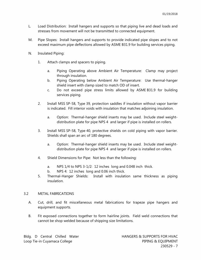
01/19/2018
Bldg. D Central Chilled Water Loop Tie-in Cuyamaca College
HANGERS & SUPPORTS FOR HVAC PIPING & EQUIPMENT
230529 - 7
L. Load Distribution: Install hangers and supports so that piping live and dead loads and stresses from movement will not be transmitted to connected equipment.
M. Pipe Slopes: Install hangers and supports to provide indicated pipe slopes and to not exceed maximum pipe deflections allowed by ASME B31.9 for building services piping.
N. Insulated Piping:
1. Attach clamps and spacers to piping.
a. Piping Operating above Ambient Air Temperature: Clamp may project through insulation.
b. Piping Operating below Ambient Air Temperature: Use thermal-hanger shield insert with clamp sized to match OD of insert.
c. Do not exceed pipe stress limits allowed by ASME B31.9 for building services piping.
2. Install MSS SP-58, Type 39, protection saddles if insulation without vapor barrier is indicated. Fill interior voids with insulation that matches adjoining insulation.
a. Option: Thermal-hanger shield inserts may be used. Include steel weight-distribution plate for pipe NPS 4 and larger if pipe is installed on rollers.
3. Install MSS SP-58, Type 40, protective shields on cold piping with vapor barrier. Shields shall span an arc of 180 degrees.
a. Option: Thermal-hanger shield inserts may be used. Include steel weight-distribution plate for pipe NPS 4 and larger if pipe is installed on rollers.
4. Shield Dimensions for Pipe: Not less than the following:
a. NPS 1/4 to NPS 3-1/2: 12 inches long and 0.048 inch thick. b. NPS 4: 12 inches long and 0.06 inch thick.
5. Thermal-Hanger Shields: Install with insulation same thickness as piping insulation.
3.2 METAL FABRICATIONS
A. Cut, drill, and fit miscellaneous metal fabrications for trapeze pipe hangers and equipment supports.
B. Fit exposed connections together to form hairline joints. Field weld connections that cannot be shop welded because of shipping size limitations.
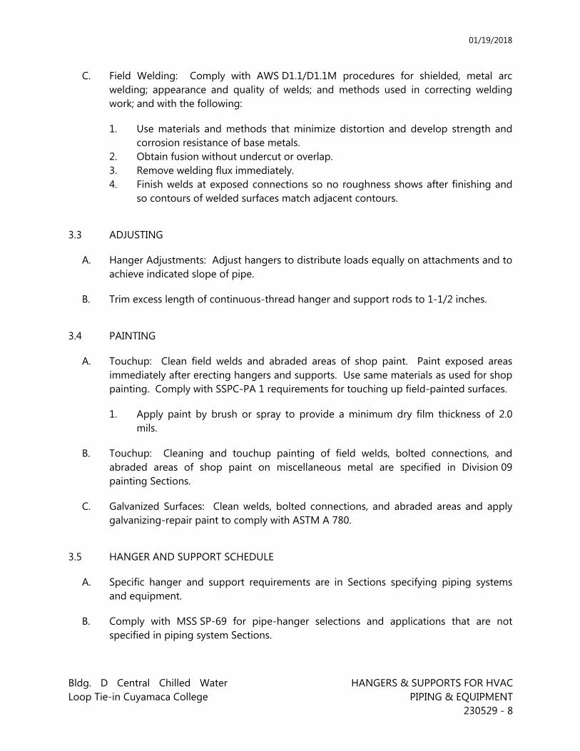
01/19/2018
Bldg. D Central Chilled Water Loop Tie-in Cuyamaca College
HANGERS & SUPPORTS FOR HVAC PIPING & EQUIPMENT
230529 - 8
C. Field Welding: Comply with AWS D1.1/D1.1M procedures for shielded, metal arc welding; appearance and quality of welds; and methods used in correcting welding work; and with the following:
1. Use materials and methods that minimize distortion and develop strength and corrosion resistance of base metals.
2. Obtain fusion without undercut or overlap. 3. Remove welding flux immediately. 4. Finish welds at exposed connections so no roughness shows after finishing and
so contours of welded surfaces match adjacent contours.
3.3 ADJUSTING
A. Hanger Adjustments: Adjust hangers to distribute loads equally on attachments and to achieve indicated slope of pipe.
B. Trim excess length of continuous-thread hanger and support rods to 1-1/2 inches.
3.4 PAINTING
A. Touchup: Clean field welds and abraded areas of shop paint. Paint exposed areas immediately after erecting hangers and supports. Use same materials as used for shop painting. Comply with SSPC-PA 1 requirements for touching up field-painted surfaces.
1. Apply paint by brush or spray to provide a minimum dry film thickness of 2.0 mils.
B. Touchup: Cleaning and touchup painting of field welds, bolted connections, and abraded areas of shop paint on miscellaneous metal are specified in Division 09 painting Sections.
C. Galvanized Surfaces: Clean welds, bolted connections, and abraded areas and apply galvanizing-repair paint to comply with ASTM A 780.
3.5 HANGER AND SUPPORT SCHEDULE
A. Specific hanger and support requirements are in Sections specifying piping systems and equipment.
B. Comply with MSS SP-69 for pipe-hanger selections and applications that are not specified in piping system Sections.

01/19/2018
Bldg. D Central Chilled Water Loop Tie-in Cuyamaca College
HANGERS & SUPPORTS FOR HVAC PIPING & EQUIPMENT
230529 - 9
C. Use hangers and supports with galvanized metallic coatings for piping and equipment that will not have field-applied finish.
D. Use nonmetallic coatings on attachments for electrolytic protection where attachments are in direct contact with copper tubing.
E. Use carbon-steel pipe hangers and supports and attachments for general service applications.
F. Use stainless-steel pipe hangers attachments for hostile environment applications.
G. Use copper-plated pipe hangers and copper attachments for copper piping and tubing.
H. Use padded hangers for piping that is subject to scratching.
I. Use thermal-hanger shield inserts for insulated piping and tubing.
J. Horizontal-Piping Hangers and Supports: Unless otherwise indicated and except as specified in piping system Sections, install the following types:
1. Adjustable, Steel Clevis Hangers (MSS Type 1): For suspension of noninsulated or insulated, stationary pipes NPS 1/2 to NPS 30.
2. Yoke-Type Pipe Clamps (MSS Type 2): For suspension of up to 1050 deg F (566 deg C), pipes NPS 4 to NPS 24 (DN 100 to DN 600), requiring up to 4 inches (100 mm) of insulation.
3. Carbon- or Alloy-Steel, Double-Bolt Pipe Clamps (MSS Type 3): For suspension of pipes NPS 3/4 to NPS 36 (DN 20 to DN 900), requiring clamp flexibility and up to 4 inches (100 mm) of insulation.
4. Steel Pipe Clamps (MSS Type 4): For suspension of cold and hot pipes NPS 1/2 to NPS 24 (DN 15 to DN 600) if little or no insulation is required.
5. Pipe Hangers (MSS Type 5): For suspension of pipes NPS 1/2 to NPS 4 (DN 15 to DN 100), to allow off-center closure for hanger installation before pipe erection.
6. Adjustable, Swivel Split- or Solid-Ring Hangers (MSS Type 6): For suspension of noninsulated, stationary pipes NPS 3/4 to NPS 8 (DN 20 to DN 200).
7. Adjustable, Steel Band Hangers (MSS Type 7): For suspension of noninsulated, stationary pipes NPS 1/2 to NPS 8 (DN 15 to DN 200).
8. Adjustable Band Hangers (MSS Type 9): For suspension of noninsulated, stationary pipes NPS 1/2 to NPS 8 (DN 15 to DN 200).
9. Adjustable, Swivel-Ring Band Hangers (MSS Type 10): For suspension of noninsulated, stationary pipes NPS 1/2 to NPS 8 (DN 15 to DN 200).
10. Split Pipe Ring with or without Turnbuckle Hangers (MSS Type 11): For suspension of noninsulated, stationary pipes NPS 3/8 to NPS 8 (DN 10 to DN 200).
11. Extension Hinged or Two-Bolt Split Pipe Clamps (MSS Type 12): For suspension of noninsulated, stationary pipes NPS 3/8 to NPS 3 (DN 10 to DN 80).
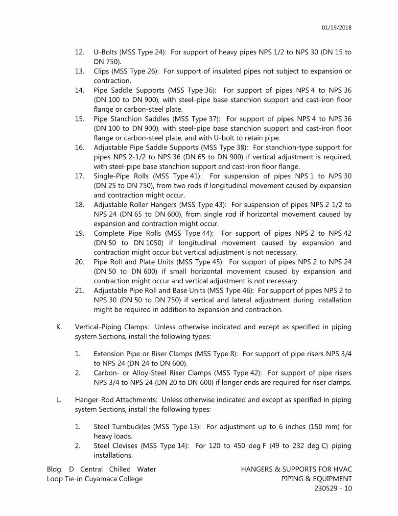
01/19/2018
Bldg. D Central Chilled Water Loop Tie-in Cuyamaca College
HANGERS & SUPPORTS FOR HVAC PIPING & EQUIPMENT
230529 - 10
12. U-Bolts (MSS Type 24): For support of heavy pipes NPS 1/2 to NPS 30 (DN 15 to DN 750).
13. Clips (MSS Type 26): For support of insulated pipes not subject to expansion or contraction.
14. Pipe Saddle Supports (MSS Type 36): For support of pipes NPS 4 to NPS 36 (DN 100 to DN 900), with steel-pipe base stanchion support and cast-iron floor flange or carbon-steel plate.
15. Pipe Stanchion Saddles (MSS Type 37): For support of pipes NPS 4 to NPS 36 (DN 100 to DN 900), with steel-pipe base stanchion support and cast-iron floor flange or carbon-steel plate, and with U-bolt to retain pipe.
16. Adjustable Pipe Saddle Supports (MSS Type 38): For stanchion-type support for pipes NPS 2-1/2 to NPS 36 (DN 65 to DN 900) if vertical adjustment is required, with steel-pipe base stanchion support and cast-iron floor flange.
17. Single-Pipe Rolls (MSS Type 41): For suspension of pipes NPS 1 to NPS 30 (DN 25 to DN 750), from two rods if longitudinal movement caused by expansion and contraction might occur.
18. Adjustable Roller Hangers (MSS Type 43): For suspension of pipes NPS 2-1/2 to NPS 24 (DN 65 to DN 600), from single rod if horizontal movement caused by expansion and contraction might occur.
19. Complete Pipe Rolls (MSS Type 44): For support of pipes NPS 2 to NPS 42 (DN 50 to DN 1050) if longitudinal movement caused by expansion and contraction might occur but vertical adjustment is not necessary.
20. Pipe Roll and Plate Units (MSS Type 45): For support of pipes NPS 2 to NPS 24 (DN 50 to DN 600) if small horizontal movement caused by expansion and contraction might occur and vertical adjustment is not necessary.
21. Adjustable Pipe Roll and Base Units (MSS Type 46): For support of pipes NPS 2 to NPS 30 (DN 50 to DN 750) if vertical and lateral adjustment during installation might be required in addition to expansion and contraction.
K. Vertical-Piping Clamps: Unless otherwise indicated and except as specified in piping system Sections, install the following types:
1. Extension Pipe or Riser Clamps (MSS Type 8): For support of pipe risers NPS 3/4 to NPS 24 (DN 24 to DN 600).
2. Carbon- or Alloy-Steel Riser Clamps (MSS Type 42): For support of pipe risers NPS 3/4 to NPS 24 (DN 20 to DN 600) if longer ends are required for riser clamps.
L. Hanger-Rod Attachments: Unless otherwise indicated and except as specified in piping system Sections, install the following types:
1. Steel Turnbuckles (MSS Type 13): For adjustment up to 6 inches (150 mm) for heavy loads.
2. Steel Clevises (MSS Type 14): For 120 to 450 deg F (49 to 232 deg C) piping installations.
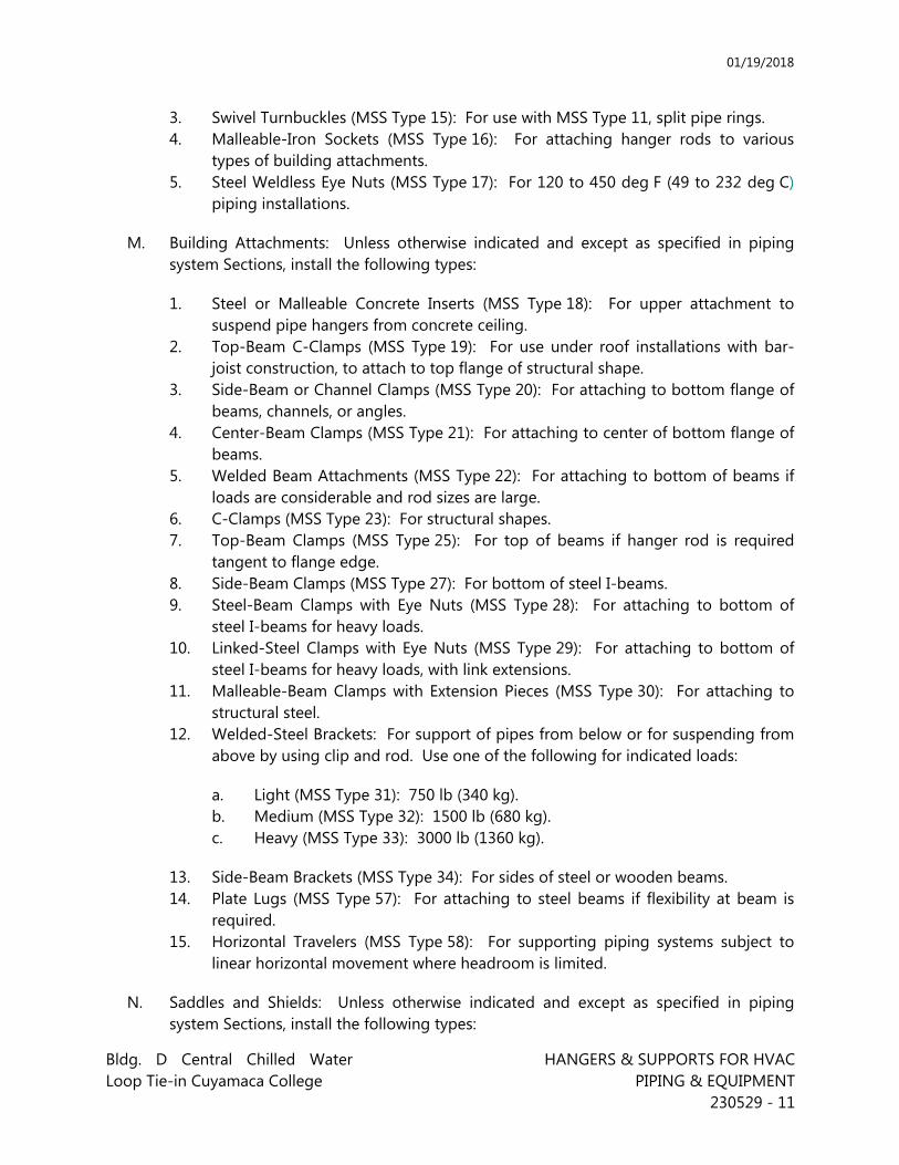
01/19/2018
Bldg. D Central Chilled Water Loop Tie-in Cuyamaca College
HANGERS & SUPPORTS FOR HVAC PIPING & EQUIPMENT
230529 - 11
3. Swivel Turnbuckles (MSS Type 15): For use with MSS Type 11, split pipe rings. 4. Malleable-Iron Sockets (MSS Type 16): For attaching hanger rods to various
types of building attachments. 5. Steel Weldless Eye Nuts (MSS Type 17): For 120 to 450 deg F (49 to 232 deg C)
piping installations.
M. Building Attachments: Unless otherwise indicated and except as specified in piping system Sections, install the following types:
1. Steel or Malleable Concrete Inserts (MSS Type 18): For upper attachment to suspend pipe hangers from concrete ceiling.
2. Top-Beam C-Clamps (MSS Type 19): For use under roof installations with bar-joist construction, to attach to top flange of structural shape.
3. Side-Beam or Channel Clamps (MSS Type 20): For attaching to bottom flange of beams, channels, or angles.
4. Center-Beam Clamps (MSS Type 21): For attaching to center of bottom flange of beams.
5. Welded Beam Attachments (MSS Type 22): For attaching to bottom of beams if loads are considerable and rod sizes are large.
6. C-Clamps (MSS Type 23): For structural shapes. 7. Top-Beam Clamps (MSS Type 25): For top of beams if hanger rod is required
tangent to flange edge. 8. Side-Beam Clamps (MSS Type 27): For bottom of steel I-beams. 9. Steel-Beam Clamps with Eye Nuts (MSS Type 28): For attaching to bottom of
steel I-beams for heavy loads. 10. Linked-Steel Clamps with Eye Nuts (MSS Type 29): For attaching to bottom of
steel I-beams for heavy loads, with link extensions. 11. Malleable-Beam Clamps with Extension Pieces (MSS Type 30): For attaching to
structural steel. 12. Welded-Steel Brackets: For support of pipes from below or for suspending from
above by using clip and rod. Use one of the following for indicated loads:
a. Light (MSS Type 31): 750 lb (340 kg). b. Medium (MSS Type 32): 1500 lb (680 kg). c. Heavy (MSS Type 33): 3000 lb (1360 kg).
13. Side-Beam Brackets (MSS Type 34): For sides of steel or wooden beams. 14. Plate Lugs (MSS Type 57): For attaching to steel beams if flexibility at beam is
required. 15. Horizontal Travelers (MSS Type 58): For supporting piping systems subject to
linear horizontal movement where headroom is limited.
N. Saddles and Shields: Unless otherwise indicated and except as specified in piping system Sections, install the following types:
01/19/2018
Bldg. D Central Chilled Water Loop Tie-in Cuyamaca College
HANGERS & SUPPORTS FOR HVAC PIPING & EQUIPMENT
230529 - 12
1. Steel-Pipe-Covering Protection Saddles (MSS Type 39): To fill interior voids with insulation that matches adjoining insulation.
2. Protection Shields (MSS Type 40): Of length recommended in writing by manufacturer to prevent crushing insulation.
3. Thermal-Hanger Shield Inserts: For supporting insulated pipe.
O. Spring Hangers and Supports: Unless otherwise indicated and except as specified in piping system Sections, install the following types:
1. Restraint-Control Devices (MSS Type 47): Where indicated to control piping movement.
2. Spring Cushions (MSS Type 48): For light loads if vertical movement does not exceed 1-1/4 inches (32 mm).
3. Spring-Cushion Roll Hangers (MSS Type 49): For equipping Type 41, roll hanger with springs.
4. Spring Sway Braces (MSS Type 50): To retard sway, shock, vibration, or thermal expansion in piping systems.
5. Variable-Spring Hangers (MSS Type 51): Preset to indicated load and limit variability factor to 25 percent to allow expansion and contraction of piping system from hanger.
6. Variable-Spring Base Supports (MSS Type 52): Preset to indicated load and limit variability factor to 25 percent to allow expansion and contraction of piping system from base support.
7. Variable-Spring Trapeze Hangers (MSS Type 53): Preset to indicated load and limit variability factor to 25 percent to allow expansion and contraction of piping system from trapeze support.
8. Constant Supports: For critical piping stress and if necessary to avoid transfer of stress from one support to another support, critical terminal, or connected equipment. Include auxiliary stops for erection, hydrostatic test, and load-adjustment capability. These supports include the following types:
a. Horizontal (MSS Type 54): Mounted horizontally. b. Vertical (MSS Type 55): Mounted vertically. c. Trapeze (MSS Type 56): Two vertical-type supports and one trapeze
member.
P. Comply with MSS SP-69 for trapeze pipe-hanger selections and applications that are not specified in piping system Sections.
Q. Comply with MFMA-103 for metal framing system selections and applications that are not specified in piping system Sections.
R. Use powder-actuated fasteners or mechanical-expansion anchors instead of building attachments where required in concrete construction.
01/19/2018
Bldg. D Central Chilled Water Loop Tie-in Cuyamaca College
HANGERS & SUPPORTS FOR HVAC PIPING & EQUIPMENT
230529 - 13
END OF SECTION 230529

01/19/2018
Bldg. D Central Chilled Water Loop Tie-in VIBRATION AND SEISMIC CONTROLS Cuyamaca College FOR HVAC PIPING AND EQUIPMENT 230548-1
SECTION 230548 - VIBRATION AND SEISMIC CONTROLS FOR HVAC PIPING AND EQUIPMENT
PART 1 - GENERAL
1.1 RELATED DOCUMENTS
A. Drawings and general provisions of the Contract, including General and Supplementary Conditions and Division 1 Specification Sections, apply to this Section.
1.2 SUMMARY
A. This Section includes the following: 1. Spring hangers. 2. Spring hangers with vertical-limit stops. 3. Pipe riser resilient supports. 4. Resilient pipe guides. 5. Seismic snubbers. 6. Restraining cables.
1.3 DEFINITIONS
A. OSHPD: Office of Statewide Health Planning & Development for the State of California. OSHPD assigns a unique anchorage preapproval "R" number to each seismic restraint it tests. The number describes a specific device applied as tested.
1.4 CODE AND STANDARDS REQUIREMENTS
A. Typical Applicable Codes and Standards 1. Seismic design shall be in accordance with the ASCE 7-10, Chapter 13 – Seismic
Design Requirements for Nonstructural Components (with all modifications specified in California Building Code section 1616A)..
2. Attachments for floor- or roof-mounted equipment weighing less than 400 lbs need not be designed to resist seismic loads. Attachments for vibration-isolated and suspended equipment weighing less than 20 lbs need not be designed to resist seismic loads. However, attachment of such equipment is still required.
3. Seismic sway bracing of suspended piping and ductwork shall be installed in accordance with the 2011 Mason Industries Seismic Restraint Guidelines for Suspended Systems.
B. Manufacturer’s/Contractors Responsibilities 1. All anchorages and/or seismic restraints shall be designed by a registered
professional civil or structural engineer licensed in the state of California. Design shall include: a) Number, size, and location of anchors for floor or roof-mounted
equipment. For curb mounted equipment, provide design of attachment of both the unit to the curb and the curb to the structure. In addition,
01/19/2018
Bldg. D Central Chilled Water Loop Tie-in VIBRATION AND SEISMIC CONTROLS Cuyamaca College FOR HVAC PIPING AND EQUIPMENT 230548-2
provide calculations, test data or California OSHPD approval number substantiating that the curb can accept the prescribed seismic forces.
b) Number, size and location of vibration isolators, seismic restraint devices and their anchorage for vibration-isolated and suspended equipment. Provide calculations, test data or California OSHPD approval number verifying the horizontal and vertical ratings of the seismic restraint devices.
c) Number, size and location of braces and anchors for suspended piping and ductwork on shop drawings. 1) The contractor must select a single seismic restraint system pre-
designed to meet the requirements of the 2013 California Building Code such as the 2011 Mason Industries Seismic Restraint Guidelines for Suspended Systems.
2) Details or designs from two different seismic restraint guidelines are not acceptable. Installations not addressed by the selected system must be designed, detailed and submitted along with the shop drawings.
3) Maximum seismic loads shall be indicated on drawings at each brace location. Drawings shall bear the stamp and signature of the registered professional civil or structural engineer licensed in the state of California who designed the layout of the braces.
1.5 SUBMITTALS
A. Product Data: Include load deflection curves for each vibration isolation device.
B. Shop Drawings: Signed and sealed by a qualified professional engineer. Include the following: 1. Design Calculations: Calculate requirements for selecting vibration isolators and
seismic restraints and for designing vibration isolation bases. 2. Vibration Isolation Base Details: Detail fabrication, including anchorages and
attachments to structure and to supported equipment. Include auxiliary motor slides and rails, base weights, equipment static loads, power transmission, component misalignment, and cantilever loads.
3. Seismic-Restraint Details: Detail fabrication and attachment of seismic restraints. Show anchorage details and indicate quantity, diameter, and depth of penetration of anchors.
4. Expansion Joint/Seismic Connector: Include required unit sizing and displacement compensation capability and temperature and pressure ratings.
C. Welding certificates.
D. Manufacturer Seismic Qualification Certification: Submit certification that all specified equipment will withstand seismic forces identified in "Performance Requirements" Article above. Include the following:
01/19/2018
Bldg. D Central Chilled Water Loop Tie-in VIBRATION AND SEISMIC CONTROLS Cuyamaca College FOR HVAC PIPING AND EQUIPMENT 230548-3
1. Basis for Certification: Indicate whether withstand certification is based on actual test of assembled components or on calculations. a) The term "withstand" means "the unit will remain in place without
separation of any parts from the device when subjected to the seismic forces specified and the unit will be fully operational after the seismic event."
2. Dimensioned Outline Drawings of Equipment Unit: Identify center of gravity and locate and describe mounting and anchorage provisions.
3. Detailed description of equipment anchorage devices on which the certification is based and their installation requirements.
1.6 QUALITY ASSURANCE
A. Seismic-restraint devices shall have horizontal and vertical load testing and analysis performed according to OSHPD and shall bear anchorage preapproval "R" number, from OSHPD or another agency acceptable to authorities having jurisdiction, showing maximum seismic-restraint ratings. Ratings based on independent testing are preferred to ratings based on calculations. If preapproved ratings are not available, submittals based on independent testing are preferred. Calculations (including combining shear and tensile loads) to support seismic-restraint designs must be signed and sealed by a qualified professional engineer. Testing and calculations must include both shear and tensile loads and 1 test or analysis at 45 degrees to the weakest mode.
B. Welding: Qualify procedures and personnel according to AWS D1.1, "Structural Welding Code--Steel."
1.7 COORDINATION
A. Coordinate size and location of concrete bases. Cast anchor-bolt inserts into base. Concrete, reinforcement, and formwork requirements are specified in structural drawings.
B. Coordinate installation of roof curbs, equipment supports, and roof penetrations.
C. Comprehensive Shop Drawings: Coordinate requirements of this section with comprehensive shop drawings required under Division 23, Section “Mechanical General Requirements.” Submit a complete and comprehensive set of shop drawings in one package prior to material fabrication, order, and installation.
01/19/2018
Bldg. D Central Chilled Water Loop Tie-in VIBRATION AND SEISMIC CONTROLS Cuyamaca College FOR HVAC PIPING AND EQUIPMENT 230548-4
D. Commissioning: Comprehensive Commissioning is an integral part of the work required. Provide comprehensive Commissioning of Mechanical systems in accordance with Division 01 Section “Commissioning” and as specified elsewhere in these Specifications. The work of this Section includes cooperation and assistance with the Commissioning Authority to provide a fully Commissioned system. Review the commissioning requirements of the project and provide required support, including but not limited to, systems operation and adjustment, material and equipment submittals and documentation, systems start-up and testing, attendance at regular Commissioning meetings, cooperation with the Commissioning Authority and other trades in addressing and solving questions, conflicts and other issues that occur during the construction process.
1.8 EXTRA MATERIALS
A. Furnish extra materials described below that match products installed and that are packaged with protective covering for storage and identified with labels describing contents. 1. Seismic Snubber Units: Furnish one set of replacement inserts for all snubbers.
PART 2 - PRODUCTS
2.1 MANUFACTURERS
A. In other Part 2 articles where subparagraph titles below introduce lists, the following requirements apply for product selection: 1. Manufacturers: Subject to compliance with requirements, available manufacture
offering products that may be incorporated into the work include, but are not limited to manufacturers specified.
2.2 VIBRATION ISOLATORS
A. Manufacturers: 1. Mason Industries, Inc. 2. Kinetics Noise Control, Inc. 3. M.W. Sausse and Co.
B. Spring Hangers: Combination coil-spring and elastomeric-insert hanger with spring and insert in compression. Mason Type 3N or equal. 1. Frame: Steel, fabricated for connection to threaded hanger rods and to allow for
a maximum of 30 degrees of angular hanger-rod misalignment without binding or reducing isolation efficiency.
2. Outside Spring Diameter: Not less than 80 percent of the compressed height of the spring at rated load.
3. Minimum Additional Travel: 50 percent of the required deflection at rated load. 4. Lateral Stiffness: More than 80 percent of the rated vertical stiffness.
01/19/2018
Bldg. D Central Chilled Water Loop Tie-in VIBRATION AND SEISMIC CONTROLS Cuyamaca College FOR HVAC PIPING AND EQUIPMENT 230548-5
5. Overload Capacity: Support 200 percent of rated load, fully compressed, without deformation or failure.
6. Elastomeric Element: Molded, oil-resistant rubber or neoprene. Steel-washer-reinforced cup to support spring and bushing projecting through bottom of frame.
C. Pipe Riser Resilient Support: All-directional, acoustical pipe anchor consisting of 2 steel tubes separated by a minimum of 1/2-inch thick, 60-durometer neoprene. Include steel and neoprene vertical-limit stops arranged to prevent vertical travel in both directions. Design support for a maximum load on the isolation material of 500 psig and for equal resistance in all directions. Mason Type ADA or equal.
D. Resilient Pipe Guides: Telescopic arrangement of 2 steel tubes separated by a minimum of 1/2-inch thick, 60-durometer neoprene. Factory set guide height with a shear pin to allow vertical motion due to pipe expansion and contraction. Shear pin shall be removable and reinsertable to allow for selection of pipe movement. Guides shall be capable of motion to meet location requirements. Mason Type VSG or equal.
2.3 SEISMIC-RESTRAINT DEVICES
A. Manufacturers: 1. Kinetics Noise Control, Inc. 2. Mason Industries, Inc. 3. TOLCO Incorporated.
B. Resilient Isolation Washers and Bushings: 1-piece, molded, bridge-bearing neoprene complying with AASHTO M 251 and having a durometer of 60, plus or minus 5, with a flat washer face. Mason Type HG or equal.
C. Restraining Cables: Galvanized steel aircraft cables with end connections made of steel assemblies that swivel to final installation angle and utilize two clamping bolts for cable engagement. Mason Type SCB or equal.
D. Anchor Bolts: Seismic-rated, drill-in, and stud-wedge or female-wedge type. Select anchor bolts with strength required for anchor and as tested according to ASTM E 488/E 488M.
2.4 EXPANSION JOINT / SEISMIC CONNECTOR
A. Pipe Expansion Joint / Seismic Connectors for piping shall be of the braided stainless steel type. Joints to consist of two flexible sections of hose and braid, two 30 degree elbows, and a 60 degree return. Flexible hose section to be stainless steel, close pitch, angular corrugated hose with a braided outer covering of stainless steel. End connections to match connecting piping. Overall length to allow for +/- 4-inch in any direction. Provide units to allow for greater movement where required to meet structural seismic joint requirements.
01/19/2018
Bldg. D Central Chilled Water Loop Tie-in VIBRATION AND SEISMIC CONTROLS Cuyamaca College FOR HVAC PIPING AND EQUIPMENT 230548-6
B. Manufacturers: Subject to compliance with requirements, provide products by the manufacturers specified. 1. Mason Industries, Inc
2.5 FACTORY FINISHES
A. Manufacturer's standard prime-coat finish ready for field painting.
B. Finish: Manufacturer's standard paint applied to factory-assembled and -tested equipment before shipping. 1. Powder coating on springs and housings. 2. All hardware shall be electrogalvanized. Hot-dip galvanize metal components for
exterior use. 3. Baked enamel for metal components on isolators for interior use. 4. Color-code or otherwise mark vibration isolation and seismic-control devices to
indicate capacity range.
PART 3 - EXECUTION
3.1 EXAMINATION
A. Examine areas and equipment to receive vibration isolation and seismic-control devices for compliance with requirements, installation tolerances, and other conditions affecting performance.
B. Examine roughing-in of reinforcement and cast-in-place anchors to verify actual locations before installation.
C. Proceed with installation only after unsatisfactory conditions have been corrected.
3.2 INSTALLATION
A. Install roof curbs, equipment supports, and roof penetrations as specified in structural drawings.
B. Install restraining cables at each trapeze and individual pipe hanger. At trapeze anchor locations, shackle piping to trapeze. Install cables so they do not bend across sharp edges of adjacent equipment or building structure.
C. Install steel angles or channel, sized to prevent buckling, clamped with ductile-iron clamps to hanger rods for trapeze and individual pipe hangers. At trapeze anchor locations, shackle piping to trapeze. Requirements apply equally to hanging equipment. Do not weld angles to rods.
D. Install seismic snubbers on isolated equipment. Locate snubbers as close as possible to vibration isolators and bolt to equipment base and supporting structure.
01/19/2018
Bldg. D Central Chilled Water Loop Tie-in VIBRATION AND SEISMIC CONTROLS Cuyamaca College FOR HVAC PIPING AND EQUIPMENT 230548-7
E. Install resilient bolt isolation washers on equipment anchor bolts.
3.3 FIELD QUALITY CONTROL
A. A factory trained representative shall review all installations of vibration control products and seismic restraint devices and provide a letter of compliance with the manufacturer’s installation requirements, project specifications and local code requirements.
B. Testing: Perform the following field quality-control testing: 1. Isolator seismic-restraint clearance. 2. Isolator deflection. 3. Snubber minimum clearances. 4. Piping Expansion Joint/Seismic Connection clearance.
3.4 ADJUSTING
A. Adjust isolators after piping systems have been filled and equipment is at operating weight.
B. Adjust limit stops on restrained spring isolators to mount equipment at normal operating height. After equipment installation is complete, adjust limit stops so they are out of contact during normal operation.
C. Adjust active height of spring isolators.
D. Adjust seismic restraints to permit free movement of equipment within normal mode of operation.
E. Adjust snubbers according to manufacturer’s written instructions.
F. Torque anchor bolts according to equipment manufacturer's written recommendations to resist seismic forces.
3.5 CLEANING
A. After completing equipment installation, inspect vibration isolation and seismic-control devices. Remove paint splatters and other spots, dirt, and debris.
3.6 DEMONSTRATION
A. Engage a factory-authorized service representative to train Owner's maintenance personnel to adjust, operate, and maintain air-mounting systems. Refer to Division 1 Section "Procedures."
END OF SECTION 230548
01/19/2018
Bldg. D Central Chilled Water Loop Tie-in Cuyamaca College
IDENTIFICATION FOR HVAC PIPING & EQUIPMENT
230553 - 1
SECTION 230553 - IDENTIFICATION FOR HVAC PIPING AND EQUIPMENT
PART 1 - GENERAL
1.1 RELATED DOCUMENTS
A. Drawings and general provisions of the Contract, including General and Supplementary Conditions and Division 01 Specification Sections, apply to this Section.
1.2 SUMMARY
A. Section Includes: 1. Warning signs and labels. 2. Pipe labels. 3. Stencils. 4. Valve tags. 5. Warning tags.
1.3 SUBMITTALS
A. Product Data: For each type of product indicated.
B. Samples: For color, letter style, and graphic representation required for each identification material and device.
C. Equipment Label Schedule: Include a listing of all equipment to be labeled with the proposed content for each label.
D. Valve numbering scheme.
E. Valve Schedules: For each piping system to include in maintenance manuals.
1.4 COORDINATION
A. Coordinate installation of identifying devices with completion of covering and painting of surfaces where devices are to be applied.
B. Coordinate installation of identifying devices with locations of access panels and doors.
C. Install identifying devices before installing acoustical ceilings and similar concealment.
01/19/2018
Bldg. D Central Chilled Water Loop Tie-in Cuyamaca College
IDENTIFICATION FOR HVAC PIPING & EQUIPMENT
230553 - 2
PART 2 - PRODUCTS
2.1 WARNING SIGNS AND LABELS
A. Material and Thickness: Multilayer, multicolor, plastic labels for mechanical engraving, 1/8 inch thick, and having predrilled holes for attachment hardware.
B. Letter Color: Black.
C. Background Color: Yellow.
D. Maximum Temperature: Able to withstand temperatures up to 160 deg F (71 deg C).
E. Minimum Label Size: Length and width vary for required label content, but not less than 2-1/2 by 3/4 inch (64 by 19 mm).
F. Minimum Letter Size: 1/4 inch (6.4 mm) for name of units if viewing distance is less than 24 inches (600 mm), 1/2 inch (13 mm) for viewing distances up to 72 inches (1830 mm), and proportionately larger lettering for greater viewing distances. Include secondary lettering two-thirds to three-fourths the size of principal lettering.
G. Fasteners: Stainless-steel rivets or self-tapping screws.
H. Adhesive: Contact-type permanent adhesive, compatible with label and with substrate.
I. Label Content: Include caution and warning information, plus emergency notification instructions.
2.2 PIPE LABELS
A. General Requirements for Manufactured Pipe Labels: Preprinted, color-coded, with lettering indicating service, and showing flow direction.
B. Pretensioned Pipe Labels: Precoiled, semirigid plastic formed to cover full circumference of pipe and to attach to pipe without fasteners or adhesive.
C. Self-Adhesive Pipe Labels: Printed plastic with contact-type, permanent-adhesive backing.
D. Pipe Label Contents: Include identification of piping service using same designations or abbreviations as used on Drawings, pipe size, and an arrow indicating flow direction.
01/19/2018
Bldg. D Central Chilled Water Loop Tie-in Cuyamaca College
IDENTIFICATION FOR HVAC PIPING & EQUIPMENT
230553 - 3
1. Flow-Direction Arrows: Integral with piping system service lettering to accommodate both directions, or as separate unit on each pipe label to indicate flow direction.
2. Lettering Size: At least 1-1/2 inches (38 mm) high.
2.3 STENCILS
A. Stencils: Prepared with letter sizes according to ASME A13.1 for piping; minimum letter height of 1-1/4 inches (32 mm) for ducts; and minimum letter height of 3/4 inch (19 mm) for access panel and door labels, equipment labels, and similar operational instructions.
1. Stencil Material: Fiberboard or metal. 2. Stencil Paint: Exterior, gloss, alkyd enamel black unless otherwise indicated.
Paint may be in pressurized spray-can form. 3. Identification Paint: Exterior, alkyd enamel in colors according to ASME A13.1
unless otherwise indicated.
2.4 VALVE TAGS
A. Valve Tags: Stamped or engraved with 1/4-inch (6.4-mm) letters for piping system abbreviation and 1/2-inch (13-mm) numbers.
1. Tag Material: Brass, 0.032-inch minimum thickness, and having predrilled or stamped holes for attachment hardware.
2. Fasteners: Brass wire-link or beaded chain; or S-hook.
B. Valve Schedules: For each piping system, on 8-1/2-by-11-inch (A4) bond paper. Tabulate valve number, piping system, system abbreviation (as shown on valve tag), location of valve (room or space), normal-operating position (open, closed, or modulating), and variations for identification. Mark valves for emergency shutoff and similar special uses.
1. Valve-tag schedule shall be included in operation and maintenance data.
2.5 WARNING TAGS
A. Warning Tags: Preprinted or partially preprinted, accident-prevention tags, of plasticized card stock with matte finish suitable for writing.
1. Size: Approximately 4 by 7 inches. 2. Fasteners: Reinforced grommet and wire or string.
01/19/2018
Bldg. D Central Chilled Water Loop Tie-in Cuyamaca College
IDENTIFICATION FOR HVAC PIPING & EQUIPMENT
230553 - 4
3. Nomenclature: Large-size primary caption such as "DANGER," "CAUTION," or "DO NOT OPERATE."
4. Color: Yellow background with black lettering.
PART 3 - EXECUTION
3.1 PREPARATION
A. Clean piping and equipment surfaces of substances that could impair bond of identification devices, including dirt, oil, grease, release agents, and incompatible primers, paints, and encapsulants.
3.2 EQUIPMENT LABEL INSTALLATION
A. Install or permanently fasten labels on each major item of mechanical equipment.
B. Locate equipment labels where accessible and visible.
3.3 PIPE LABEL INSTALLATION
A. Piping Color-Coding: Painting of piping is specified in Division 09 Section "High-Performance Coatings."
B. Stenciled Pipe Label Option: Stenciled labels may be provided instead of manufactured pipe labels, at Installer's option. Install stenciled pipe labels with painted, color-coded bands or rectangles, complying with ASME A13.1, on each piping system.
1. Identification Paint: Use for contrasting background. 2. Stencil Paint: Use for pipe marking.
C. Locate pipe labels where piping is exposed or above accessible ceilings in finished spaces; machine rooms; accessible maintenance spaces such as shafts, tunnels, and plenums; and exterior exposed locations as follows:
1. Near each valve and control device. 2. Near each branch connection, excluding short takeoffs for fixtures and terminal
units. Where flow pattern is not obvious, mark each pipe at branch. 3. Near penetrations through walls, floors, ceilings, and inaccessible enclosures. 4. At access doors, manholes, and similar access points that permit view of
concealed piping. 5. Near major equipment items and other points of origination and termination.
01/19/2018
Bldg. D Central Chilled Water Loop Tie-in Cuyamaca College
IDENTIFICATION FOR HVAC PIPING & EQUIPMENT
230553 - 5
6. Spaced at maximum intervals of 20 feet (15 m) along each run. Reduce intervals to 10 feet (7.6 m) in areas of congested piping and equipment.
7. On piping above removable acoustical ceilings. Omit intermediately spaced labels.
D. Pipe Label Color Schedule:
1. Chilled-Water Piping:
a. Background Color: White. b. Letter Color: Blue.
3.4 VALVE-TAG INSTALLATION
A. Install tags on valves and control devices in piping systems, except check valves; valves within factory-fabricated equipment units; shutoff valves; faucets; convenience and lawn-watering hose connections; and HVAC terminal devices and similar roughing-in connections of end-use fixtures and units. List tagged valves in a valve schedule.
B. Valve-Tag Application Schedule: Tag valves according to size, shape, and color scheme and with captions similar to those indicated in the following subparagraphs:
1. Valve-Tag Size and Shape:
a. Chilled Water: 2 inches (50 mm), round
2. Valve-Tag Color:
a. Chilled Water: Blue.
3. Letter Color:
a. Chilled Water: White.
3.5 WARNING-TAG INSTALLATION
A. Write required message on, and attach warning tags to, equipment and other items where required.
END OF SECTION 230553
01/19/2018
Bldg. D Central Chilled Water Loop Tie-in HVAC PIPING INSULATION Cuyamaca College 230719 - 1
SECTION 230719 - HVAC PIPING INSULATION
PART 1 - GENERAL
1.1 RELATED DOCUMENTS
A. Drawings and general provisions of the Contract, including General and Supplementary Conditions and Division 01 Specification Sections, apply to this Section.
1.2 SUMMARY
A. Section includes insulating the following HVAC piping systems: 1. Chilled-water, indoors and outdoors.
B. Related Sections:
1. Division 23 Section "HVAC Equipment Insulation." 2. Division 23 Section "Hydronic Distribution" pipe insulation in underground
piping outside the building.
1.3 SUBMITTALS
A. Product Data: For each type of product indicated. Include thermal conductivity, water-vapor permeance thickness, and jackets (both factory and field applied if any).
B. Shop Drawings: Include plans, elevations, sections, details, and attachments to other work.
1. Detail application of protective shields, saddles, and inserts at hangers for each type of insulation and hanger.
2. Detail insulation application at pipe expansion joints for each type of insulation. 3. Detail insulation application at elbows, fittings, flanges, valves, and specialties for
each type of insulation. 4. Detail removable insulation at piping specialties. 5. Detail application of field-applied jackets. 6. Detail application at linkages of control devices.
C. Samples: For each type of insulation and jacket indicated. Identify each Sample, describing product and intended use. 1. Manufacturer's Color Charts: For products where color is specified, show the full
range of colors available for each type of finish material.
01/19/2018
Bldg. D Central Chilled Water Loop Tie-in HVAC PIPING INSULATION Cuyamaca College 230719 - 2
D. Qualification Data: For qualified Installer.
E. Material Test Reports: From a qualified testing agency acceptable to authorities having jurisdiction indicating, interpreting, and certifying test results for compliance of insulation materials, sealers, attachments, cements, and jackets, with requirements indicated. Include dates of tests and test methods employed.
F. Field quality-control reports.
1.4 QUALITY ASSURANCE
A. Installer Qualifications: Skilled mechanics who have successfully completed an apprenticeship program or another craft training program certified by the Department of Labor, Bureau of Apprenticeship and Training.
B. Surface-Burning Characteristics: For insulation and related materials, as determined by testing identical products according to ASTM E 84, by a testing and inspecting agency acceptable to authorities having jurisdiction. Factory label insulation and jacket materials and adhesive, mastic, tapes, and cement material containers, with appropriate markings of applicable testing agency.
1. Insulation Installed Indoors: Flame-spread index of 25 or less, and smoke-developed index of 50 or less.
2. Insulation Installed Outdoors: Flame-spread index of 75 or less, and smoke-developed index of 150 or less.
1.5 DELIVERY, STORAGE, AND HANDLING
A. Packaging: Insulation material containers shall be marked by manufacturer with appropriate ASTM standard designation, type and grade, and maximum use temperature.
1.6 COORDINATION
A. Coordinate sizes and locations of supports, hangers, and insulation shields specified in Division 23 Section "Hangers and Supports for HVAC Piping and Equipment."
B. Coordinate clearance requirements with piping Installer for piping insulation application. Before preparing piping Shop Drawings, establish and maintain clearance requirements for installation of insulation and field-applied jackets and finishes and for space required for maintenance.
C. Coordinate installation and testing of heat tracing.
01/19/2018
Bldg. D Central Chilled Water Loop Tie-in HVAC PIPING INSULATION Cuyamaca College 230719 - 3
1.7 SCHEDULING
A. Schedule insulation application after pressure testing systems and, where required, after installing and testing heat tracing. Insulation application may begin on segments that have satisfactory test results.
B. Complete installation and concealment of plastic materials as rapidly as possible in each area of construction.
PART 2 - PRODUCTS
2.1 INSULATION MATERIALS
A. Comply with requirements in "Piping Insulation Schedule, General," "Indoor Piping Insulation Schedule," "Outdoor, Aboveground Piping Insulation Schedule," and "Outdoor, Underground Piping Insulation Schedule" articles for where insulating materials shall be applied.
B. Products shall not contain asbestos, lead, mercury, or mercury compounds.
C. Products that come in contact with stainless steel shall have a leachable chloride content of less than 50 ppm when tested according to ASTM C 871.
D. Insulation materials for use on austenitic stainless steel shall be qualified as acceptable according to ASTM C 795.
E. Foam insulation materials shall not use CFC or HCFC blowing agents in the manufacturing process.
F. Calcium Silicate:
1. Products: Subject to compliance with requirements, available products that may be incorporated into the Work include, but are not limited to, the following:
a. Industrial Insulation Group (IIG); Thermo-12 Gold.
2. Preformed Pipe Sections: Flat-, curved-, and grooved-block sections of noncombustible, inorganic, hydrous calcium silicate with a non-asbestos fibrous reinforcement. Comply with ASTM C 533, Type I.
3. Flat-, curved-, and grooved-block sections of noncombustible, inorganic, hydrous calcium silicate with a non-asbestos fibrous reinforcement. Comply with ASTM C 533, Type I.
01/19/2018
Bldg. D Central Chilled Water Loop Tie-in HVAC PIPING INSULATION Cuyamaca College 230719 - 4
4. Prefabricated Fitting Covers: Comply with ASTM C 450 and ASTM C 585 for dimensions used in preforming insulation to cover valves, elbows, tees, and flanges.
G. Cellular Glass: Inorganic, incombustible, foamed or cellulated glass with annealed, rigid, hermetically sealed cells. Factory-applied jacket requirements are specified in "Factory-Applied Jackets" Article.
1. Products: Subject to compliance with requirements, available products that may be incorporated into the Work include, but are not limited to, the following:
a. Pittsburgh Corning Corporation; Foamglas.
2. Block Insulation: ASTM C 552, Type I. 3. Special-Shaped Insulation: ASTM C 552, Type III. 4. Board Insulation: ASTM C 552, Type IV. 5. Preformed Pipe Insulation without Jacket: Comply with ASTM C 552, Type II,
Class 1. 6. Preformed Pipe Insulation with Factory-Applied ASJ-SSL: Comply with
ASTM C 552, Type II, Class 2. 7. Factory fabricate shapes according to ASTM C 450 and ASTM C 585.
H. Mineral-Fiber Blanket Insulation: Mineral or glass fibers bonded with a thermosetting resin. Comply with ASTM C 553, Type II and ASTM C 1290, Type I with factory-applied vinyl jacket. Factory-applied jacket requirements are specified in "Factory-Applied Jackets" Article.
1. Products: Subject to compliance with requirements, available products that may be incorporated into the Work include, but are not limited to, the following:
a. CertainTeed Corp.; SoftTouch Duct Wrap. b. Johns Manville; Microlite. c. Knauf Insulation; Friendly Feel Duct Wrap. d. Manson Insulation Inc.; Alley Wrap. e. Owens Corning; SOFTR All-Service Duct Wrap.
I. Mineral-Fiber, Preformed Pipe Insulation:
1. Products: Subject to compliance with requirements, available products that may be incorporated into the Work include, but are not limited to, the following:
a. Fibrex Insulations Inc.; Coreplus 1200. b. Johns Manville; Micro-Lok. c. Knauf Insulation; 1000-Degree Pipe Insulation. d. Manson Insulation Inc.; Alley-K. e. Owens Corning; Fiberglas Pipe Insulation.
01/19/2018
Bldg. D Central Chilled Water Loop Tie-in HVAC PIPING INSULATION Cuyamaca College 230719 - 5
2. Type I, 850 deg F Materials: Mineral or glass fibers bonded with a thermosetting resin. Comply with ASTM C 547, Type I, Grade A, with factory-applied ASJ-SSL. Factory-applied jacket requirements are specified in "Factory-Applied Jackets" Article.
J. Mineral-Fiber, Pipe Insulation Wicking System: Preformed pipe insulation complying with ASTM C 547, Type I, Grade A, with absorbent cloth factory-applied to the entire inside surface of preformed pipe insulation and extended through the longitudinal joint to outside surface of insulation under insulation jacket. Factory apply a white, polymer, vapor-retarder jacket with self-sealing adhesive tape seam and evaporation holes running continuously along the longitudinal seam, exposing the absorbent cloth.
1. Products: Subject to compliance with requirements, available products that may be incorporated into the Work include, but are not limited to, the following:
a. Knauf Insulation; Permawick Pipe Insulation. b. Owens Corning; VaporWick Pipe Insulation.
K. Mineral-Fiber, Pipe and Tank Insulation: Mineral or glass fibers bonded with a thermosetting resin. Semirigid board material with factory-applied ASJ jacket] complying with ASTM C 1393, Type II or Type IIIA Category 2, or with properties similar to ASTM C 612, Type IB. Nominal density is 2.5 lb/cu. ft. or more. Thermal conductivity (k-value) at 100 deg F is 0.29 Btu x in./h x sq. ft. x deg F or less. Factory-applied jacket requirements are specified in "Factory-Applied Jackets" Article.
1. Products: Subject to compliance with requirements, available products that may be incorporated into the Work include, but are not limited to, the following:
a. CertainTeed Corp.; CrimpWrap. b. Johns Manville; MicroFlex. c. Knauf Insulation; Pipe and Tank Insulation. d. Manson Insulation Inc.; AK Flex. e. Owens Corning; Fiberglas Pipe and Tank Insulation.
2.2 ADHESIVES
A. Materials shall be compatible with insulation materials, jackets, and substrates and for bonding insulation to itself and to surfaces to be insulated unless otherwise indicated.
B. Calcium Silicate Adhesive: Fibrous, sodium-silicate-based adhesive with a service temperature range of 50 to 800 deg F .
1. Products: Subject to compliance with requirements, available products that may be incorporated into the Work include, but are not limited to, the following:
01/19/2018
Bldg. D Central Chilled Water Loop Tie-in HVAC PIPING INSULATION Cuyamaca College 230719 - 6
a. Childers Brand, Specialty Construction Brands, Inc., a business of H. B. Fuller Company; CP-97.
b. Eagle Bridges - Marathon Industries; 290. c. Foster Brand, Specialty Construction Brands, Inc., a business of H. B. Fuller
Company; 81-27. d. Mon-Eco Industries, Inc.; 22-30. e. Vimasco Corporation; 760.
2. For indoor applications, use adhesive that has a VOC content of 80 g/L or less when calculated according to 40 CFR 59, Subpart D (EPA Method 24).
3. Use adhesive that complies with the testing and product requirements of the California Department of Health Services' "Standard Practice for the Testing of Volatile Organic Emissions from Various Sources Using Small-Scale Environmental Chambers," including 2004 Addenda.
C. Cellular-Glass Adhesive: Two-component, thermosetting urethane adhesive containing no flammable solvents, with a service temperature range of minus 100 to plus 200 deg F .
1. Products: Subject to compliance with requirements, available products that may be incorporated into the Work include, but are not limited to, the following:
a. Foster Brand, Specialty Construction Brands, Inc., a business of H. B. Fuller Company; 81-84.
2. For indoor applications, use adhesive that has a VOC content of 50 g/L or less when calculated according to 40 CFR 59, Subpart D (EPA Method 24).
3. Use adhesive that complies with the testing and product requirements of the California Department of Health Services' "Standard Practice for the Testing of Volatile Organic Emissions from Various Sources Using Small-Scale Environmental Chambers," including 2004 Addenda.
D. Mineral-Fiber Adhesive: Comply with MIL-A-3316C, Class 2, Grade A.
1. Products: Subject to compliance with requirements, available products that may be incorporated into the Work include, but are not limited to, the following:
a. Childers Brand, Specialty Construction Brands, Inc., a business of H. B. Fuller Company; CP-127.
b. Eagle Bridges - Marathon Industries; 225. c. Foster Brand, Specialty Construction Brands, Inc., a business of H. B. Fuller
Company; 85-60/85-70. d. Mon-Eco Industries, Inc.; 22-25.
01/19/2018
Bldg. D Central Chilled Water Loop Tie-in HVAC PIPING INSULATION Cuyamaca College 230719 - 7
2. For indoor applications, use adhesive that has a VOC content of 80 g/L or less when calculated according to 40 CFR 59, Subpart D (EPA Method 24).
3. Use adhesive that complies with the testing and product requirements of the California Department of Health Services' "Standard Practice for the Testing of Volatile Organic Emissions from Various Sources Using Small-Scale Environmental Chambers," including 2004 Addenda.
E. ASJ Adhesive, and FSK and PVDC Jacket Adhesive: Comply with MIL-A-3316C, Class 2, Grade A for bonding insulation jacket lap seams and joints.
1. Products: Subject to compliance with requirements, available products that may be incorporated into the Work include, but are not limited to, the following:
a. Childers Brand, Specialty Construction Brands, Inc., a business of H. B. Fuller Company; CP-82.
b. Eagle Bridges - Marathon Industries; 225. c. Foster Brand, Specialty Construction Brands, Inc., a business of H. B. Fuller
Company; 85-50. d. Mon-Eco Industries, Inc.; 22-25.
2. For indoor applications, use adhesive that has a VOC content of 50 g/L or less when calculated according to 40 CFR 59, Subpart D (EPA Method 24).
3. Use adhesive that complies with the testing and product requirements of the California Department of Health Services' "Standard Practice for the Testing of Volatile Organic Emissions from Various Sources Using Small-Scale Environmental Chambers," including 2004 Addenda.
F. PVC Jacket Adhesive: Compatible with PVC jacket.
1. Products: Subject to compliance with requirements, available products that may be incorporated into the Work include, but are not limited to, the following:
a. Dow Corning Corporation; 739, Dow Silicone. b. Johns Manville; Zeston Perma-Weld, CEEL-TITE Solvent Welding Adhesive. c. P.I.C. Plastics, Inc.; Welding Adhesive. d. Speedline Corporation; Polyco VP Adhesive.
2. For indoor applications, use adhesive that has a VOC content of 50 g/L or less when calculated according to 40 CFR 59, Subpart D (EPA Method 24).
3. Use adhesive that complies with the testing and product requirements of the California Department of Health Services' "Standard Practice for the Testing of Volatile Organic Emissions from Various Sources Using Small-Scale Environmental Chambers," including 2004 Addenda.
01/19/2018
Bldg. D Central Chilled Water Loop Tie-in HVAC PIPING INSULATION Cuyamaca College 230719 - 8
2.3 MASTICS
A. Materials shall be compatible with insulation materials, jackets, and substrates; comply with MIL-PRF-19565C, Type II.
1. For indoor applications, use mastics that have a VOC content of 50 g/L or less when calculated according to 40 CFR 59, Subpart D (EPA Method 24).
B. Vapor-Barrier Mastic: Water based; suitable for indoor use on below-ambient services.
1. Products: Subject to compliance with requirements, available products that may be incorporated into the Work include, but are not limited to, the following:
a. Foster Brand, Specialty Construction Brands, Inc., a business of H. B. Fuller Company; 30-80/30-90.
b. Vimasco Corporation; 749.
2. Water-Vapor Permeance: ASTM E 96/E 96M, Procedure B, 0.013 perm at 43-mil dry film thickness.
3. Service Temperature Range: Minus 20 to plus 180 deg F. 4. Solids Content: ASTM D 1644, 58 percent by volume and 70 percent by weight. 5. Color: White.
C. Vapor-Barrier Mastic: Solvent based; suitable for indoor use on below-ambient services.
1. Products: Subject to compliance with requirements, available products that may be incorporated into the Work include, but are not limited to, the following:
a. Childers Brand, Specialty Construction Brands, Inc., a business of H. B. Fuller Company; CP-30.
b. Eagle Bridges - Marathon Industries; 501. c. Foster Brand, Specialty Construction Brands, Inc., a business of H. B. Fuller
Company; 30-35. d. Mon-Eco Industries, Inc.; 55-10. e.
2. Water-Vapor Permeance: ASTM F 1249, 0.05 perm at 35-mil dry film thickness. 3. Service Temperature Range: 0 to 180 deg F . 4. Solids Content: ASTM D 1644, 44 percent by volume and 62 percent by weight. 5. Color: White.
D. Vapor-Barrier Mastic: Solvent based; suitable for outdoor use on below-ambient services.
01/19/2018
Bldg. D Central Chilled Water Loop Tie-in HVAC PIPING INSULATION Cuyamaca College 230719 - 9
1. Products: Subject to compliance with requirements, available products that may be incorporated into the Work include, but are not limited to, the following:
a. Childers Brand, Specialty Construction Brands, Inc., a business of H. B. Fuller Company; Encacel.
b. Eagle Bridges - Marathon Industries; 570. c. Foster Brand, Specialty Construction Brands, Inc., a business of H. B. Fuller
Company; 60-95/60-96.
2. Water-Vapor Permeance: ASTM F 1249, 0.05 perm at 30-mil dry film thickness. 3. Service Temperature Range: Minus 50 to plus 220 deg F. 4. Solids Content: ASTM D 1644, 33 percent by volume and 46 percent by weight. 5. Color: White.
E. Breather Mastic: Water based; suitable for indoor and outdoor use on above-ambient services.
1. Products: Subject to compliance with requirements, available products that may be incorporated into the Work include, but are not limited to, the following:
a. Childers Brand, Specialty Construction Brands, Inc., a business of H. B. Fuller Company; CP-10.
b. Eagle Bridges - Marathon Industries; 550. c. Foster Brand, Specialty Construction Brands, Inc., a business of H. B. Fuller
Company; 46-50. d. Mon-Eco Industries, Inc.; 55-50. e. Vimasco Corporation; WC-1/WC-5.
2. Water-Vapor Permeance: ASTM F 1249, 1.8 perms at 0.0625-inch dry film thickness.
3. Service Temperature Range: Minus 20 to plus 180 deg F . 4. Solids Content: 60 percent by volume and 66 percent by weight. 5. Color: White.
2.4 LAGGING ADHESIVES
A. Description: Comply with MIL-A-3316C, Class I, Grade A and shall be compatible with insulation materials, jackets, and substrates.
1. For indoor applications, use lagging adhesives that have a VOC content of 50 g/L or less when calculated according to 40 CFR 59, Subpart D (EPA Method 24).
2. Products: Subject to compliance with requirements, available products that may be incorporated into the Work include, but are not limited to, the following:
01/19/2018
Bldg. D Central Chilled Water Loop Tie-in HVAC PIPING INSULATION Cuyamaca College 230719 - 10
a. Childers Brand, Specialty Construction Brands, Inc., a business of H. B. Fuller Company; CP-50 AHV2.
b. Foster Brand, Specialty Construction Brands, Inc., a business of H. B. Fuller Company; 30-36.
c. Vimasco Corporation; 713 and 714.
3. Fire-resistant, water-based lagging adhesive and coating for use indoors to adhere fire-resistant lagging cloths over pipe insulation.
4. Service Temperature Range: 0 to plus 180 deg F . 5. Color: White.
2.5 SEALANTS
A. Joint Sealants:
1. Joint Sealants for Cellular-Glass, Phenolic, and Polyisocyanurate Products: Subject to compliance with requirements, available products that may be incorporated into the Work include, but are not limited to, the following:
a. Childers Brand, Specialty Construction Brands, Inc., a business of H. B. Fuller Company; CP-76.
b. Eagle Bridges - Marathon Industries; 405. c. Foster Brand, Specialty Construction Brands, Inc., a business of H. B. Fuller
Company; 30-45. d. Mon-Eco Industries, Inc.; 44-05. e. Pittsburgh Corning Corporation; Pittseal 444. f.
2. Joint Sealants for Polystyrene Products: Subject to compliance with requirements, available products that may be incorporated into the Work include, but are not limited to, the following:
a. Childers Brand, Specialty Construction Brands, Inc., a business of H. B. Fuller Company; CP-70.
b. Eagle Bridges - Marathon Industries; 405. c. Foster Brand, Specialty Construction Brands, Inc., a business of H. B. Fuller
Company; 30-45. d. Mon-Eco Industries, Inc.; 44-05.
3. Materials shall be compatible with insulation materials, jackets, and substrates. 4. Permanently flexible, elastomeric sealant. 5. Service Temperature Range: Minus 100 to plus 300 deg F . 6. Color: White or gray.
01/19/2018
Bldg. D Central Chilled Water Loop Tie-in HVAC PIPING INSULATION Cuyamaca College 230719 - 11
7. For indoor applications, use sealants that have a VOC content of 420 g/L or less when calculated according to 40 CFR 59, Subpart D (EPA Method 24).
8. Use sealants that comply with the testing and product requirements of the California Department of Health Services' "Standard Practice for the Testing of Volatile Organic Emissions from Various Sources Using Small-Scale Environmental Chambers," including 2004 Addenda.
B. FSK and Metal Jacket Flashing Sealants:
1. Products: Subject to compliance with requirements, available products that may be incorporated into the Work include, but are not limited to, the following:
a. Childers Brand, Specialty Construction Brands, Inc., a business of H. B. Fuller Company; CP-76.
b. Eagle Bridges - Marathon Industries; 405. c. Foster Brand, Specialty Construction Brands, Inc., a business of H. B. Fuller
Company; 95-44. d. Mon-Eco Industries, Inc.; 44-05.
2. Materials shall be compatible with insulation materials, jackets, and substrates. 3. Fire- and water-resistant, flexible, elastomeric sealant. 4. Service Temperature Range: Minus 40 to plus 250 deg F. 5. Color: Aluminum. 6. For indoor applications, use sealants that have a VOC content of 420 g/L or less
when calculated according to 40 CFR 59, Subpart D (EPA Method 24). 7. Use sealants that comply with the testing and product requirements of the
California Department of Health Services' "Standard Practice for the Testing of Volatile Organic Emissions from Various Sources Using Small-Scale Environmental Chambers," including 2004 Addenda.
C. ASJ Flashing Sealants, and Vinyl, PVDC, and PVC Jacket Flashing Sealants:
1. Products: Subject to compliance with requirements, available products that may be incorporated into the Work include, but are not limited to, the following:
a. Childers Brand, Specialty Construction Brands, Inc., a business of H. B. Fuller Company; CP-76.
2. Materials shall be compatible with insulation materials, jackets, and substrates. 3. Fire- and water-resistant, flexible, elastomeric sealant. 4. Service Temperature Range: Minus 40 to plus 250 deg F. 5. Color: White. 6. For indoor applications, use sealants that have a VOC content of 420 g/L or less
when calculated according to 40 CFR 59, Subpart D (EPA Method 24).
01/19/2018
Bldg. D Central Chilled Water Loop Tie-in HVAC PIPING INSULATION Cuyamaca College 230719 - 12
7. Use sealants that comply with the testing and product requirements of the California Department of Health Services' "Standard Practice for the Testing of Volatile Organic Emissions from Various Sources Using Small-Scale Environmental Chambers," including 2004 Addenda.
2.6 FACTORY-APPLIED JACKETS
A. Insulation system schedules indicate factory-applied jackets on various applications. When factory-applied jackets are indicated, comply with the following:
1. ASJ: White, kraft-paper, fiberglass-reinforced scrim with aluminum-foil backing; complying with ASTM C 1136, Type I.
2. ASJ-SSL: ASJ with self-sealing, pressure-sensitive, acrylic-based adhesive covered by a removable protective strip; complying with ASTM C 1136, Type I.
3. FSK Jacket: Aluminum-foil, fiberglass-reinforced scrim with kraft-paper backing; complying with ASTM C 1136, Type II.
4. FSP Jacket: Aluminum-foil, fiberglass-reinforced scrim with polyethylene backing; complying with ASTM C 1136, Type II.
5. PVDC Jacket for Indoor Applications: 4-mil- thick, white PVDC biaxially oriented barrier film with a permeance at 0.02 perm when tested according to ASTM E 96/E 96M and with a flame-spread index of 5 and a smoke-developed index of 20 when tested according to ASTM E 84.
a. Products: Subject to compliance with requirements, available products that may be incorporated into the Work include, but are not limited to, the following:
1) Dow Chemical Company (The); Saran 540 Vapor Retarder Film and Saran 560 Vapor Retarder Film.
6. PVDC Jacket for Outdoor Applications: 6-mil- thick, white PVDC biaxially oriented barrier film with a permeance at 0.01 perm when tested according to ASTM E 96/E 96M and with a flame-spread index of 5 and a smoke-developed index of 25 when tested according to ASTM E 84.
a. Products: Subject to compliance with requirements, available products that may be incorporated into the Work include, but are not limited to, the following:
1) Dow Chemical Company (The); Saran 540 Vapor Retarder Film and Saran 560 Vapor Retarder Film.
7. PVDC-SSL Jacket: PVDC jacket with a self-sealing, pressure-sensitive, acrylic-based adhesive covered by a removable protective strip.
01/19/2018
Bldg. D Central Chilled Water Loop Tie-in HVAC PIPING INSULATION Cuyamaca College 230719 - 13
a. Products: Subject to compliance with requirements, available products that may be incorporated into the Work include, but are not limited to, the following:
1) Dow Chemical Company (The); Saran 540 Vapor Retarder Film and Saran 560 Vapor Retarder Film.
8. Vinyl Jacket: White vinyl with a permeance of 1.3 perms when tested according to ASTM E 96/E 96M, Procedure A, and complying with NFPA 90A and NFPA 90B.
2.7 FIELD-APPLIED FABRIC-REINFORCING MESH
A. Woven Glass-Fiber Fabric: Approximately 2 oz./sq. yd. with a thread count of 10 strands by 10 strands/sq. in. for covering pipe and pipe fittings.
1. Products: Subject to compliance with requirements, available products that may be incorporated into the Work include, but are not limited to, the following:
a. Childers Brand, Specialty Construction Brands, Inc., a business of H. B. Fuller Company; Chil-Glas Number 10.
B. Woven Polyester Fabric: Approximately 1 oz./sq. yd. with a thread count of 10 strands by 10 strands/sq. in. , in a Leno weave, for pipe.
1. Products: Subject to compliance with requirements, available products that may be incorporated into the Work include, but are not limited to, the following:
a. Foster Brand, Specialty Construction Brands, Inc., a business of H. B. Fuller Company; Mast-A-Fab.
b. Vimasco Corporation; Elastafab 894.
2.8 FIELD-APPLIED CLOTHS
A. Woven Glass-Fiber Fabric: Comply with MIL-C-20079H, Type I, plain weave, and presized a minimum of 8 oz./sq. yd. .
1. Products: Subject to compliance with requirements, available products that may be incorporated into the Work include, but are not limited to, the following:
a. Alpha Associates, Inc.; Alpha-Maritex 84215 and 84217/9485RW, Luben 59.
2.9 FIELD-APPLIED JACKETS
A. Field-applied jackets shall comply with ASTM C 921, Type I, unless otherwise indicated.
01/19/2018
Bldg. D Central Chilled Water Loop Tie-in HVAC PIPING INSULATION Cuyamaca College 230719 - 14
B. FSK Jacket: Aluminum-foil-face, fiberglass-reinforced scrim with kraft-paper backing.
C. PVC Jacket: High-impact-resistant, UV-resistant PVC complying with ASTM D 1784, Class 16354-C; thickness as scheduled; roll stock ready for shop or field cutting and forming. Thickness is indicated in field-applied jacket schedules.
1. Products: Subject to compliance with requirements, available products that may be incorporated into the Work include, but are not limited to, the following:
a. Johns Manville; Zeston. b. P.I.C. Plastics, Inc.; FG Series. c. Proto Corporation; LoSmoke. d. Speedline Corporation; SmokeSafe.
2. Adhesive: As recommended by jacket material manufacturer. 3. Color: Color-code jackets based on application. . 4. Factory-fabricated fitting covers to match jacket if available; otherwise, field
fabricate.
a. Shapes: 45- and 90-degree, short- and long-radius elbows, tees, valves, flanges, unions, reducers, end caps, soil-pipe hubs, traps, mechanical joints, and P-trap and supply covers for lavatories.
D. Metal Jacket:
1. Products: Subject to compliance with requirements, available products that may be incorporated into the Work include, but are not limited to, the following:
a. Childers Brand, Specialty Construction Brands, Inc., a business of H. B. Fuller Company; Metal Jacketing Systems.
b. ITW Insulation Systems; Aluminum and Stainless Steel Jacketing. c. RPR Products, Inc.; Insul-Mate.
2. Aluminum Jacket: Comply with ASTM B 209, Alloy 3003, 3005, 3105, or 5005, Temper H-14.
a. Factory cut and rolled to size. b. Finish and thickness are indicated in field-applied jacket schedules. c. Moisture Barrier for Outdoor Applications: 3-mil- (0.075-mm-) thick, heat-
bonded polyethylene and kraft paper. d. Factory-Fabricated Fitting Covers:
1) Same material, finish, and thickness as jacket. 2) Preformed 2-piece or gore, 45- and 90-degree, short- and long-
radius elbows. 3) Tee covers.
01/19/2018
Bldg. D Central Chilled Water Loop Tie-in HVAC PIPING INSULATION Cuyamaca College 230719 - 15
4) Flange and union covers. 5) End caps. 6) Beveled collars. 7) Valve covers. 8) Field fabricate fitting covers only if factory-fabricated fitting covers
are not available.
E. Underground Direct-Buried Jacket: 125-mil- thick vapor barrier and waterproofing membrane consisting of a rubberized bituminous resin reinforced with a woven-glass fiber or polyester scrim and laminated aluminum foil.
1. Products: Subject to compliance with requirements, available products that may be incorporated into the Work include, but are not limited to, the following:
a. Pittsburgh Corning Corporation; Pittwrap. b. Polyguard Products, Inc.; Insulrap No Torch 125.
F. Self-Adhesive Outdoor Jacket: 60-mil- thick, laminated vapor barrier and waterproofing membrane for installation over insulation located aboveground outdoors; consisting of a rubberized bituminous resin on a crosslaminated polyethylene film covered with stucco-embossed aluminum-foil facing.
1. Products: Subject to compliance with requirements, available products that may be incorporated into the Work include, but are not limited to, the following:
a. Polyguard Products, Inc.; Alumaguard 60.
G. PVDC Jacket for Indoor Applications: 4-mil- thick, white PVDC biaxially oriented barrier film with a permeance at 0.02 perms when tested according to ASTM E 96/E 96M and with a flame-spread index of 5 and a smoke-developed index of 20 when tested according to ASTM E 84.
1. Products: Subject to compliance with requirements, available products that may be incorporated into the Work include, but are not limited to, the following:
a. Dow Chemical Company (The); Saran 540 Vapor Retarder Film.
H. PVDC-SSL Jacket: PVDC jacket with a self-sealing, pressure-sensitive, acrylic-based adhesive covered by a removable protective strip.
1. Products: Subject to compliance with requirements, available products that may be incorporated into the Work include, but are not limited to, the following:
a. Dow Chemical Company (The); Saran 540 Vapor Retarder Film and Saran 560 Vapor Retarder Film.
01/19/2018
Bldg. D Central Chilled Water Loop Tie-in HVAC PIPING INSULATION Cuyamaca College 230719 - 16
2.10 TAPES
A. ASJ Tape: White vapor-retarder tape matching factory-applied jacket with acrylic adhesive, complying with ASTM C 1136.
1. Products: Subject to compliance with requirements, available products that may be incorporated into the Work include, but are not limited to, the following:
a. ABI, Ideal Tape Division; 428 AWF ASJ. b. Avery Dennison Corporation, Specialty Tapes Division; Fasson 0836. c. Compac Corporation; 104 and 105. d. Venture Tape; 1540 CW Plus, 1542 CW Plus, and 1542 CW Plus/SQ.
2. Width: 3 inches . 3. Thickness: 11.5 mils . 4. Adhesion: 90 ounces force/inch in width. 5. Elongation: 2 percent. 6. Tensile Strength: 40 lbf/inch in width. 7. ASJ Tape Disks and Squares: Precut disks or squares of ASJ tape.
B. FSK Tape: Foil-face, vapor-retarder tape matching factory-applied jacket with acrylic adhesive; complying with ASTM C 1136.
1. Products: Subject to compliance with requirements, available products that may be incorporated into the Work include, but are not limited to, the following:
a. ABI, Ideal Tape Division; 491 AWF FSK. b. Avery Dennison Corporation, Specialty Tapes Division; Fasson 0827. c. Compac Corporation; 110 and 111. d. Venture Tape; 1525 CW NT, 1528 CW, and 1528 CW/SQ.
2. Width: 3 inches . 3. Thickness: 6.5 mils . 4. Adhesion: 90 ounces force/inch in width. 5. Elongation: 2 percent. 6. Tensile Strength: 40 lbf/inch in width. 7. FSK Tape Disks and Squares: Precut disks or squares of FSK tape.
C. PVC Tape: White vapor-retarder tape matching field-applied PVC jacket with acrylic adhesive; suitable for indoor and outdoor applications.
1. Products: Subject to compliance with requirements, available products that may be incorporated into the Work include, but are not limited to, the following:
a. ABI, Ideal Tape Division; 370 White PVC tape. b. Compac Corporation; 130.

01/19/2018
Bldg. D Central Chilled Water Loop Tie-in HVAC PIPING INSULATION Cuyamaca College 230719 - 17
c. Venture Tape; 1506 CW NS.
2. Width: 2 inches . 3. Thickness: 6 mils . 4. Adhesion: 64 ounces force/inch in width. 5. Elongation: 500 percent. 6. Tensile Strength: 18 lbf/inch in width.
D. Aluminum-Foil Tape: Vapor-retarder tape with acrylic adhesive.
1. Products: Subject to compliance with requirements, available products that may be incorporated into the Work include, but are not limited to, the following:
a. ABI, Ideal Tape Division; 488 AWF. b. Avery Dennison Corporation, Specialty Tapes Division; Fasson 0800. c. Compac Corporation; 120. d. Venture Tape; 3520 CW.
2. Width: 2 inches . 3. Thickness: 3.7 mils . 4. Adhesion: 100 ounces force/inch in width. 5. Elongation: 5 percent. 6. Tensile Strength: 34 lbf/inch in width.
E. PVDC Tape for Indoor Applications: White vapor-retarder PVDC tape with acrylic adhesive.
1. Products: Subject to compliance with requirements, available products that may be incorporated into the Work include, but are not limited to, the following:
a. Dow Chemical Company (The); Saran 540 Vapor Retarder Tape.
2. Width: 3 inches . 3. Film Thickness: 4 mils . 4. Adhesive Thickness: 1.5 mils . 5. Elongation at Break: 145 percent. 6. Tensile Strength: 55 lbf/inch in width.
F. PVDC Tape for Outdoor Applications: White vapor-retarder PVDC tape with acrylic adhesive.
1. Products: Subject to compliance with requirements, available products that may be incorporated into the Work include, but are not limited to, the following:
a. Dow Chemical Company (The); Saran 560 Vapor Retarder Tape.
01/19/2018
Bldg. D Central Chilled Water Loop Tie-in HVAC PIPING INSULATION Cuyamaca College 230719 - 18
2. Width: 3 inches . 3. Film Thickness: 6 mils . 4. Adhesive Thickness: 1.5 mils . 5. Elongation at Break: 145 percent. 6. Tensile Strength: 55 lbf/inch in width.
2.11 SECUREMENTS
A. Bands:
1. Products: Subject to compliance with requirements, available products that may be incorporated into the Work include, but are not limited to, the following:
a. ITW Insulation Systems; Gerrard Strapping and Seals. b. RPR Products, Inc.; Insul-Mate Strapping, Seals, and Springs.
2. Stainless Steel: ASTM A 167 or ASTM A 240/A 240M, Type 304; 0.015 inch thick, 3/4 inch wide with wing seal or closed seal.
3. Aluminum: ASTM B 209, Alloy 3003, 3005, 3105, or 5005; Temper H-14, 0.020 inch thick, 3/4 inch wide with wing seal or closed seal.
4. Springs: Twin spring set constructed of stainless steel with ends flat and slotted to accept metal bands. Spring size determined by manufacturer for application.
B. Staples: Outward-clinching insulation staples, nominal 3/4-inch- wide, stainless steel or Monel.
C. Wire: 0.062-inch soft-annealed, galvanized steel.
1. Manufacturers: Subject to compliance with requirements, available manufacturers offering products that may be incorporated into the Work include, but are not limited to, the following:
a. C & F Wire.
PART 3 - EXECUTION
3.1 EXAMINATION
A. Examine substrates and conditions for compliance with requirements for installation tolerances and other conditions affecting performance of insulation application.
1. Verify that systems to be insulated have been tested and are free of defects. 2. Verify that surfaces to be insulated are clean and dry.
01/19/2018
Bldg. D Central Chilled Water Loop Tie-in HVAC PIPING INSULATION Cuyamaca College 230719 - 19
3. Proceed with installation only after unsatisfactory conditions have been corrected.
3.2 PREPARATION
A. Surface Preparation: Clean and dry surfaces to receive insulation. Remove materials that will adversely affect insulation application.
B. Surface Preparation: Clean and prepare surfaces to be insulated. Before insulating, apply a corrosion coating to insulated surfaces as follows:
1. Stainless Steel: Coat 300 series stainless steel with an epoxy primer 5 mils thick and an epoxy finish 5 mils thick if operating in a temperature range between 140 and 300 deg F . Consult coating manufacturer for appropriate coating materials and application methods for operating temperature range.
2. Carbon Steel: Coat carbon steel operating at a service temperature between 32 and 300 deg F with an epoxy coating. Consult coating manufacturer for appropriate coating materials and application methods for operating temperature range.
C. Coordinate insulation installation with the trade installing heat tracing. Comply with requirements for heat tracing that apply to insulation.
D. Mix insulating cements with clean potable water; if insulating cements are to be in contact with stainless-steel surfaces, use demineralized water.
3.3 GENERAL INSTALLATION REQUIREMENTS
A. Install insulation materials, accessories, and finishes with smooth, straight, and even surfaces; free of voids throughout the length of piping including fittings, valves, and specialties.
B. Install insulation materials, forms, vapor barriers or retarders, jackets, and thicknesses required for each item of pipe system as specified in insulation system schedules.
C. Install accessories compatible with insulation materials and suitable for the service. Install accessories that do not corrode, soften, or otherwise attack insulation or jacket in either wet or dry state.
D. Install insulation with longitudinal seams at top and bottom of horizontal runs.
E. Install multiple layers of insulation with longitudinal and end seams staggered.
01/19/2018
Bldg. D Central Chilled Water Loop Tie-in HVAC PIPING INSULATION Cuyamaca College 230719 - 20
F. Do not weld brackets, clips, or other attachment devices to piping, fittings, and specialties.
G. Keep insulation materials dry during application and finishing.
H. Install insulation with tight longitudinal seams and end joints. Bond seams and joints with adhesive recommended by insulation material manufacturer.
I. Install insulation with least number of joints practical.
J. Where vapor barrier is indicated, seal joints, seams, and penetrations in insulation at hangers, supports, anchors, and other projections with vapor-barrier mastic.
1. Install insulation continuously through hangers and around anchor attachments. 2. For insulation application where vapor barriers are indicated, extend insulation on
anchor legs from point of attachment to supported item to point of attachment to structure. Taper and seal ends at attachment to structure with vapor-barrier mastic.
3. Install insert materials and install insulation to tightly join the insert. Seal insulation to insulation inserts with adhesive or sealing compound recommended by insulation material manufacturer.
4. Cover inserts with jacket material matching adjacent pipe insulation. Install shields over jacket, arranged to protect jacket from tear or puncture by hanger, support, and shield.
K. Apply adhesives, mastics, and sealants at manufacturer's recommended coverage rate and wet and dry film thicknesses.
L. Install insulation with factory-applied jackets as follows:
1. Draw jacket tight and smooth. 2. Cover circumferential joints with 3-inch- wide strips, of same material as
insulation jacket. Secure strips with adhesive and outward clinching staples along both edges of strip, spaced 4 inches o.c.
3. Overlap jacket longitudinal seams at least 1-1/2 inches . Install insulation with longitudinal seams at bottom of pipe. Clean and dry surface to receive self-sealing lap. Staple laps with outward clinching staples along edge at 2 inches o.c.
a. For below-ambient services, apply vapor-barrier mastic over staples.
4. Cover joints and seams with tape, according to insulation material manufacturer's written instructions, to maintain vapor seal.
5. Where vapor barriers are indicated, apply vapor-barrier mastic on seams and joints and at ends adjacent to pipe flanges and fittings.
01/19/2018
Bldg. D Central Chilled Water Loop Tie-in HVAC PIPING INSULATION Cuyamaca College 230719 - 21
M. Cut insulation in a manner to avoid compressing insulation more than 75 percent of its nominal thickness.
N. Finish installation with systems at operating conditions. Repair joint separations and cracking due to thermal movement.
O. Repair damaged insulation facings by applying same facing material over damaged areas. Extend patches at least 4 inches beyond damaged areas. Adhere, staple, and seal patches similar to butt joints.
P. For above-ambient services, do not install insulation to the following:
1. Vibration-control devices. 2. Testing agency labels and stamps. 3. Nameplates and data plates. 4. Manholes. 5. Handholes. 6. Cleanouts.
3.4 PENETRATIONS
A. Insulation Installation at Roof Penetrations: Install insulation continuously through roof penetrations.
1. Seal penetrations with flashing sealant. 2. For applications requiring only indoor insulation, terminate insulation above roof
surface and seal with joint sealant. For applications requiring indoor and outdoor insulation, install insulation for outdoor applications tightly joined to indoor insulation ends. Seal joint with joint sealant.
3. Extend jacket of outdoor insulation outside roof flashing at least 2 inches below top of roof flashing.
4. Seal jacket to roof flashing with flashing sealant.
B. Insulation Installation at Underground Exterior Wall Penetrations: Terminate insulation flush with sleeve seal. Seal terminations with flashing sealant.
C. Insulation Installation at Aboveground Exterior Wall Penetrations: Install insulation continuously through wall penetrations.
1. Seal penetrations with flashing sealant. 2. For applications requiring only indoor insulation, terminate insulation inside wall
surface and seal with joint sealant. For applications requiring indoor and outdoor insulation, install insulation for outdoor applications tightly joined to indoor insulation ends. Seal joint with joint sealant.
01/19/2018
Bldg. D Central Chilled Water Loop Tie-in HVAC PIPING INSULATION Cuyamaca College 230719 - 22
3. Extend jacket of outdoor insulation outside wall flashing and overlap wall flashing at least 2 inches .
4. Seal jacket to wall flashing with flashing sealant.
D. Insulation Installation at Interior Wall and Partition Penetrations (That Are Not Fire Rated): Install insulation continuously through walls and partitions.
E. Insulation Installation at Fire-Rated Wall and Partition Penetrations: Install insulation continuously through penetrations of fire-rated walls and partitions.
1. Comply with requirements in Division 07 Section "Penetration Firestopping" for firestopping and fire-resistive joint sealers.
F. Insulation Installation at Floor Penetrations:
1. Pipe: Install insulation continuously through floor penetrations. 2. Seal penetrations through fire-rated assemblies. Comply with requirements in
Division 07 Section "Penetration Firestopping."
3.5 GENERAL PIPE INSULATION INSTALLATION
A. Requirements in this article generally apply to all insulation materials except where more specific requirements are specified in various pipe insulation material installation articles.
B. Insulation Installation on Fittings, Valves, Strainers, Flanges, and Unions:
1. Install insulation over fittings, valves, strainers, flanges, unions, and other specialties with continuous thermal and vapor-retarder integrity unless otherwise indicated.
2. Insulate pipe elbows using preformed fitting insulation or mitered fittings made from same material and density as adjacent pipe insulation. Each piece shall be butted tightly against adjoining piece and bonded with adhesive. Fill joints, seams, voids, and irregular surfaces with insulating cement finished to a smooth, hard, and uniform contour that is uniform with adjoining pipe insulation.
3. Insulate tee fittings with preformed fitting insulation or sectional pipe insulation of same material and thickness as used for adjacent pipe. Cut sectional pipe insulation to fit. Butt each section closely to the next and hold in place with tie wire. Bond pieces with adhesive.
4. Insulate valves using preformed fitting insulation or sectional pipe insulation of same material, density, and thickness as used for adjacent pipe. Overlap adjoining pipe insulation by not less than two times the thickness of pipe insulation, or one pipe diameter, whichever is thicker. For valves, insulate up to and including the bonnets, valve stuffing-box studs, bolts, and nuts. Fill joints, seams, and irregular surfaces with insulating cement.
01/19/2018
Bldg. D Central Chilled Water Loop Tie-in HVAC PIPING INSULATION Cuyamaca College 230719 - 23
5. Insulate strainers using preformed fitting insulation or sectional pipe insulation of same material, density, and thickness as used for adjacent pipe. Overlap adjoining pipe insulation by not less than two times the thickness of pipe insulation, or one pipe diameter, whichever is thicker. Fill joints, seams, and irregular surfaces with insulating cement. Insulate strainers so strainer basket flange or plug can be easily removed and replaced without damaging the insulation and jacket. Provide a removable reusable insulation cover. For below-ambient services, provide a design that maintains vapor barrier.
6. Insulate flanges and unions using a section of oversized preformed pipe insulation. Overlap adjoining pipe insulation by not less than two times the thickness of pipe insulation, or one pipe diameter, whichever is thicker.
7. Cover segmented insulated surfaces with a layer of finishing cement and coat with a mastic. Install vapor-barrier mastic for below-ambient services and a breather mastic for above-ambient services. Reinforce the mastic with fabric-reinforcing mesh. Trowel the mastic to a smooth and well-shaped contour.
8. For services not specified to receive a field-applied jacket except for flexible elastomeric and polyolefin, install fitted PVC cover over elbows, tees, strainers, valves, flanges, and unions. Terminate ends with PVC end caps. Tape PVC covers to adjoining insulation facing using PVC tape.
9. Stencil or label the outside insulation jacket of each union with the word "union." Match size and color of pipe labels.
C. Insulate instrument connections for thermometers, pressure gages, pressure temperature taps, test connections, flow meters, sensors, switches, and transmitters on insulated pipes. Shape insulation at these connections by tapering it to and around the connection with insulating cement and finish with finishing cement, mastic, and flashing sealant.
D. Install removable insulation covers at locations indicated. Installation shall conform to the following:
1. Make removable flange and union insulation from sectional pipe insulation of same thickness as that on adjoining pipe. Install same insulation jacket as adjoining pipe insulation.
2. When flange and union covers are made from sectional pipe insulation, extend insulation from flanges or union long at least two times the insulation thickness over adjacent pipe insulation on each side of flange or union. Secure flange cover in place with stainless-steel or aluminum bands. Select band material compatible with insulation and jacket.
3. Construct removable valve insulation covers in same manner as for flanges, except divide the two-part section on the vertical center line of valve body.
4. When covers are made from block insulation, make two halves, each consisting of mitered blocks wired to stainless-steel fabric. Secure this wire frame, with its attached insulation, to flanges with tie wire. Extend insulation at least 2 inches

01/19/2018
Bldg. D Central Chilled Water Loop Tie-in HVAC PIPING INSULATION Cuyamaca College 230719 - 24
over adjacent pipe insulation on each side of valve. Fill space between flange or union cover and pipe insulation with insulating cement. Finish cover assembly with insulating cement applied in two coats. After first coat is dry, apply and trowel second coat to a smooth finish.
5. Unless a PVC jacket is indicated in field-applied jacket schedules, finish exposed surfaces with a metal jacket.
3.6 INSTALLATION OF CELLULAR-GLASS INSULATION
A. Insulation Installation on Straight Pipes and Tubes:
1. Secure each layer of insulation to pipe with wire or bands and tighten bands without deforming insulation materials.
2. Where vapor barriers are indicated, seal longitudinal seams, end joints, and protrusions with vapor-barrier mastic and joint sealant.
3. For insulation with factory-applied jackets on above-ambient services, secure laps with outward-clinched staples at 6 inches o.c.
4. For insulation with factory-applied jackets on below-ambient services, do not staple longitudinal tabs. Instead, secure tabs with additional adhesive as recommended by insulation material manufacturer and seal with vapor-barrier mastic and flashing sealant.
B. Insulation Installation on Pipe Flanges:
1. Install preformed pipe insulation to outer diameter of pipe flange. 2. Make width of insulation section same as overall width of flange and bolts, plus
twice the thickness of pipe insulation. 3. Fill voids between inner circumference of flange insulation and outer
circumference of adjacent straight pipe segments with cut sections of cellular-glass block insulation of same thickness as pipe insulation.
4. Install jacket material with manufacturer's recommended adhesive, overlap seams at least 1 inch , and seal joints with flashing sealant.
C. Insulation Installation on Pipe Fittings and Elbows:
1. Install preformed sections of same material as straight segments of pipe insulation when available. Secure according to manufacturer's written instructions.
2. When preformed sections of insulation are not available, install mitered sections of cellular-glass insulation. Secure insulation materials with wire or bands.
D. Insulation Installation on Valves and Pipe Specialties:
1. Install preformed sections of cellular-glass insulation to valve body.
01/19/2018
Bldg. D Central Chilled Water Loop Tie-in HVAC PIPING INSULATION Cuyamaca College 230719 - 25
2. Arrange insulation to permit access to packing and to allow valve operation without disturbing insulation.
3. Install insulation to flanges as specified for flange insulation application.
3.7 INSTALLATION OF FLEXIBLE ELASTOMERIC INSULATION
A. Seal longitudinal seams and end joints with manufacturer's recommended adhesive to eliminate openings in insulation that allow passage of air to surface being insulated.
B. Insulation Installation on Pipe Flanges:
1. Install pipe insulation to outer diameter of pipe flange. 2. Make width of insulation section same as overall width of flange and bolts, plus
twice the thickness of pipe insulation. 3. Fill voids between inner circumference of flange insulation and outer
circumference of adjacent straight pipe segments with cut sections of sheet insulation of same thickness as pipe insulation.
4. Secure insulation to flanges and seal seams with manufacturer's recommended adhesive to eliminate openings in insulation that allow passage of air to surface being insulated.
C. Insulation Installation on Pipe Fittings and Elbows:
1. Install mitered sections of pipe insulation. 2. Secure insulation materials and seal seams with manufacturer's recommended
adhesive to eliminate openings in insulation that allow passage of air to surface being insulated.
D. Insulation Installation on Valves and Pipe Specialties:
1. Install preformed valve covers manufactured of same material as pipe insulation when available.
2. When preformed valve covers are not available, install cut sections of pipe and sheet insulation to valve body. Arrange insulation to permit access to packing and to allow valve operation without disturbing insulation.
3. Install insulation to flanges as specified for flange insulation application. 4. Secure insulation to valves and specialties and seal seams with manufacturer's
recommended adhesive to eliminate openings in insulation that allow passage of air to surface being insulated.
3.8 INSTALLATION OF MINERAL-FIBER INSULATION
A. Insulation Installation on Straight Pipes and Tubes:
01/19/2018
Bldg. D Central Chilled Water Loop Tie-in HVAC PIPING INSULATION Cuyamaca College 230719 - 26
1. Secure each layer of preformed pipe insulation to pipe with wire or bands and tighten bands without deforming insulation materials.
2. Where vapor barriers are indicated, seal longitudinal seams, end joints, and protrusions with vapor-barrier mastic and joint sealant.
3. For insulation with factory-applied jackets on above-ambient surfaces, secure laps with outward-clinched staples at 6 inches o.c.
4. For insulation with factory-applied jackets on below-ambient surfaces, do not staple longitudinal tabs. Instead, secure tabs with additional adhesive as recommended by insulation material manufacturer and seal with vapor-barrier mastic and flashing sealant.
B. Insulation Installation on Pipe Flanges:
1. Install preformed pipe insulation to outer diameter of pipe flange. 2. Make width of insulation section same as overall width of flange and bolts, plus
twice the thickness of pipe insulation. 3. Fill voids between inner circumference of flange insulation and outer
circumference of adjacent straight pipe segments with mineral-fiber blanket insulation.
4. Install jacket material with manufacturer's recommended adhesive, overlap seams at least 1 inch , and seal joints with flashing sealant.
C. Insulation Installation on Pipe Fittings and Elbows:
1. Install preformed sections of same material as straight segments of pipe insulation when available.
2. When preformed insulation elbows and fittings are not available, install mitered sections of pipe insulation, to a thickness equal to adjoining pipe insulation. Secure insulation materials with wire or bands.
D. Insulation Installation on Valves and Pipe Specialties:
1. Install preformed sections of same material as straight segments of pipe insulation when available.
2. When preformed sections are not available, install mitered sections of pipe insulation to valve body.
3. Arrange insulation to permit access to packing and to allow valve operation without disturbing insulation.
4. Install insulation to flanges as specified for flange insulation application.
3.9 FIELD-APPLIED JACKET INSTALLATION
A. Where glass-cloth jackets are indicated, install directly over bare insulation or insulation with factory-applied jackets.

01/19/2018
Bldg. D Central Chilled Water Loop Tie-in HVAC PIPING INSULATION Cuyamaca College 230719 - 27
1. Draw jacket smooth and tight to surface with 2-inch overlap at seams and joints. 2. Embed glass cloth between two 0.062-inch- thick coats of lagging adhesive. 3. Completely encapsulate insulation with coating, leaving no exposed insulation.
B. Where FSK jackets are indicated, install as follows:
1. Draw jacket material smooth and tight. 2. Install lap or joint strips with same material as jacket. 3. Secure jacket to insulation with manufacturer's recommended adhesive. 4. Install jacket with 1-1/2-inch laps at longitudinal seams and 3-inch- wide joint
strips at end joints. 5. Seal openings, punctures, and breaks in vapor-retarder jackets and exposed
insulation with vapor-barrier mastic.
C. Where PVC jackets are indicated, install with 1-inch overlap at longitudinal seams and end joints; for horizontal applications. Seal with manufacturer's recommended adhesive.
1. Apply two continuous beads of adhesive to seams and joints, one bead under lap and the finish bead along seam and joint edge.
D. Where metal jackets are indicated, install with 2-inch overlap at longitudinal seams and end joints. Overlap longitudinal seams arranged to shed water. Seal end joints with weatherproof sealant recommended by insulation manufacturer. Secure jacket with stainless-steel bands 12 inches o.c. and at end joints.
E. Where PVDC jackets are indicated, install as follows:
1. Apply three separate wraps of filament tape per insulation section to secure pipe insulation to pipe prior to installation of PVDC jacket.
2. Wrap factory-presized jackets around individual pipe insulation sections with one end overlapping the previously installed sheet. Install presized jacket with an approximate overlap at butt joint of 2 inches over the previous section. Adhere lap seal using adhesive or SSL, and then apply 1-1/4 circumferences of appropriate PVDC tape around overlapped butt joint.
3. Continuous jacket can be spiral-wrapped around a length of pipe insulation. Apply adhesive or PVDC tape at overlapped spiral edge. When electing to use adhesives, refer to manufacturer's written instructions for application of adhesives along this spiral edge to maintain a permanent bond.
4. Jacket can be wrapped in cigarette fashion along length of roll for insulation systems with an outer circumference of 33-1/2 inches or less. The 33-1/2-inch- circumference limit allows for 2-inch- overlap seal. Using the length of roll allows for longer sections of jacket to be installed at one time. Use adhesive on the lap seal. Visually inspect lap seal for "fishmouthing," and use PVDC tape along lap seal to secure joint.
01/19/2018
Bldg. D Central Chilled Water Loop Tie-in HVAC PIPING INSULATION Cuyamaca College 230719 - 28
5. Repair holes or tears in PVDC jacket by placing PVDC tape over the hole or tear and wrapping a minimum of 1-1/4 circumferences to avoid damage to tape edges.
3.10 FINISHES
A. Pipe Insulation with ASJ, Glass-Cloth, or Other Paintable Jacket Material: Paint jacket with paint system identified below and as specified in Division 09 painting Sections.
1. Flat Acrylic Finish: Two finish coats over a primer that is compatible with jacket material and finish coat paint. Add fungicidal agent to render fabric mildew proof.
a. Finish Coat Material: Interior, flat, latex-emulsion size.
B. Flexible Elastomeric Thermal Insulation: After adhesive has fully cured, apply two coats of insulation manufacturer's recommended protective coating.
C. Color: Final color as selected by Architect. Vary first and second coats to allow visual inspection of the completed Work.
D. Do not field paint aluminum or stainless-steel jackets.
3.11 FIELD QUALITY CONTROL
A. Testing Agency: Engage a qualified testing agency to perform tests and inspections.
B. Perform tests and inspections.
C. Tests and Inspections:
1. Inspect pipe, fittings, strainers, and valves, randomly selected by Architect, by removing field-applied jacket and insulation in layers in reverse order of their installation. Extent of inspection shall be limited to three locations of straight pipe, three locations of threaded fittings, threelocations of welded fittings, two locations of threaded strainers, two locations of welded strainers, three locations of threaded valves, and three locations of flanged valves for each pipe service defined in the "Piping Insulation Schedule, General" Article.
D. All insulation applications will be considered defective Work if sample inspection reveals noncompliance with requirements.
01/19/2018
Bldg. D Central Chilled Water Loop Tie-in HVAC PIPING INSULATION Cuyamaca College 230719 - 29
3.12 PIPING INSULATION SCHEDULE, GENERAL
A. Acceptable preformed pipe and tubular insulation materials and thicknesses are identified for each piping system and pipe size range. If more than one material is listed for a piping system, selection from materials listed is Contractor's option.
B. Items Not Insulated: Unless otherwise indicated, do not install insulation on the following:
1. Drainage piping located in crawl spaces. 2. Underground piping. 3. Chrome-plated pipes and fittings unless there is a potential for personnel injury.
3.13 INDOOR PIPING INSULATION SCHEDULE
A. Chilled Water and Brine, above 40 Deg F (5 Deg C):
1. NPS 12 and Smaller: Insulation shall be the following: a. Mineral-Fiber, Preformed Pipe, Type I or Pipe Insulation Wicking System: 1-
1/2 inches thick.
3.14 OUTDOOR, ABOVEGROUND PIPING INSULATION SCHEDULE
A. Chilled Water and Brine:
1. All Pipe Sizes: Insulation shall be the following: a. Mineral-Fiber, Preformed Pipe Insulation, Type I: 3 inches thick.
3.15 INDOOR, FIELD-APPLIED JACKET SCHEDULE
A. Install jacket over insulation material. For insulation with factory-applied jacket, install the field-applied jacket over the factory-applied jacket.
B. If more than one material is listed, selection from materials listed is Contractor's option.
C. Piping, Exposed: 1. PVC, Color-Coded by Application: 30 mils thick. Color coded as below :
a. Chilled Water Supply – Light Blue b. Chilled Water Return- Dark Blue
01/19/2018
Bldg. D Central Chilled Water Loop Tie-in HVAC PIPING INSULATION Cuyamaca College 230719 - 30
3.16 OUTDOOR, FIELD-APPLIED JACKET SCHEDULE
A. Install jacket over insulation material. For insulation with factory-applied jacket, install the field-applied jacket over the factory-applied jacket.
B. If more than one material is listed, selection from materials listed is Contractor's option.
C. Piping, Exposed: 1. Aluminum, Stucco Embossedwith Z-Shaped Locking Seam: 0.032 inch thick.
END OF SECTION 230719
01/19/2018
Bldg. D Central Chilled Water Loop Tie-in HVAC INSTRUMENTATION & CONTROL Cuyamaca College 230900-1
SECTION 230900 - HVAC INSTRUMENTATION AND CONTROLS
PART 1 - GENERAL
1.1 RELATED DOCUMENTS
A. Drawings and general provisions of the Contract, including General and Supplementary Conditions and Division 1 Specification Sections, General Requirements, apply to this Section.
1.2 SUMMARY
A. This Section includes control equipment for HVAC systems and components, including control components for terminal heating and cooling units not supplied with factory-wired controls. This section includes:
1) Control equipment. Drawings
2) Software.
3) Sensors.
4) Control Instruments.
5) Controllers.
6) Wiring and conduit in connection with HVAC Instrumentation and Controls in accordance with Division 26.
7) Power supply to HVAC Instrumentation and Controls unless otherwise specified under Division 26.
8) Commissioning of HVAC Instrumentation and Controls.
9) Trending and coordination with other trades for Commissioning of HVAC Systems.
B. Related Divisions include the following:
1) Division 23: Heating, Ventilating and Air Conditioning
2) Division 26: Electrical
1.3 DEFINITIONS
A. DDC: Direct-digital controls.
B. LAN: Local area network.
C. MS/TP: Master-slave/token-passing.
01/19/2018
Bldg. D Central Chilled Water Loop Tie-in HVAC INSTRUMENTATION & CONTROL Cuyamaca College 230900-2
D. BAS: Building Automation System
E. BACnet: Building Automation and Control Network Protocol by ASHRAE
F. BTL: BACnet Test Laboratory
G. PIO: Proportional Plus Integral Plus Derivative
H. PICS: Protocol Implementation Conformance Statement
I. RTD: Resistance Temperature Detection
J. BIBBS: BACnet Interoperability Building Blocks
K. XML: Extensible Mark-up Language
L. OBIX: Open Building Information Exchange
M. SOAP: Simple Object Access Protocol
1.4 REFERENCES
A. NFPA 90 – Installation of Air Conditioning and Ventilating Systems.
B. UL 864 – Control Units for Fire Protective Signaling Systems.
C. UL 916 – Energy Management.
D. NFPA 91A – Recommended practice for smoke control systems.
E. ADA – Americans with Disabilities Act.
F. UL 508A – Manufacturer listed control panel.
G. EIA/TIA-568 – Commercial Building Wiring Standard.
H. ASHRAE – American Society of Heating Refrigerating and Air Conditioning Engineers
I. ANSI/ASHRAE Standard 135-2008 BACnet
J. ASHRAE Standard 13 Specifying Direct Digital Control Systems
K. EMC Directive 89/336/EEC (European CE Mark)
1.5 SYSTEM DESCRIPTION
01/19/2018
Bldg. D Central Chilled Water Loop Tie-in HVAC INSTRUMENTATION & CONTROL Cuyamaca College 230900-3
A. Control system consists of sensors, indicators, actuators, final control elements, interface equipment, other apparatus, and accessories to control mechanical systems.
B. A distributed control system, complete with all software and hardware functions, shall be provided and installed. System shall be completely based on ANSI/ASHRAE Standard 135-2008, BACnet. This system is to control mechanical equipment specified using native BACnet-compliant components. Non-BACnet-compliant or proprietary equipment or systems shall not be acceptable and are specifically prohibited.
C. The system shall provide capability through web services.
D. Control system includes coordination with other trades from conception to completion of project to allow for a Commissioning and Operating HVAC Control System.
E. Control System includes wiring and conduit in connection with HVAC Instrumentation and Controls.
F. Control System includes the electrical power supply to HVAC Instrumentation and Controls, unless otherwise specified under Division 26. Coordinate with Electrical Contractor and other trades. Provide a complete and operational control system.
1.6 SYSTEM PERFORMANCE
A. Comply with the following performance requirements:
1. Graphic Display Time: Display graphic with minimum 60 dynamic points with current data within 10 seconds.
2. Graphic Refresh Time: Update graphic with minimum 60 dynamic points with current data within 8 seconds.
3. Object Command: Reaction time of less than two seconds between operator command of a binary object and device reaction.
4. Object Scan: Transmit change of state and change of analog values to control units or workstation within six seconds.
5. Alarm Response Time: Annunciate alarm at workstation within 45 seconds. Multiple workstations must receive alarms within five seconds of each other.
01/19/2018
Bldg. D Central Chilled Water Loop Tie-in HVAC INSTRUMENTATION & CONTROL Cuyamaca College 230900-4
6. Program Execution Frequency: Run capability of applications as often as five seconds, but selected consistent with mechanical process under control.
7. Performance: Programmable controllers shall execute DDC PID control loops, and scan and update process values and outputs at least once per second.
8. Reporting Accuracy and Stability of Control: Report values and maintain measured variables within tolerances as follows:
9. The requirements here are state for verification and measurement purposed and do not reduce the accuracy requirements of sensors and other components specified.
a. Water Temperature: Plus or minus 1 deg F. b. Water Pressure: Plus or minus 2 percent of full scale.
1.7 SUBMITTALS
A. Provide a complete and comprehensive submittal package. Partial submittals shall not be accepted. Upon completion, submit all compliance data and project record documents.
B. Product Data: Include manufacturer's technical literature for each control device. Indicate dimensions, capacities, performance characteristics, electrical characteristics, finishes for materials, and installation and startup instructions for each type of product indicated.
1. Each control device labeled with setting or adjustable range of control.
C. Shop Drawings: Detail equipment assemblies and indicate dimensions, weights, loads, required clearances, method of field assembly, components, and location and size of each field connection.
1. Schematic flow diagrams showing the systems for pumps, coils, dampers, valves, and control devices.
2. Wiring diagrams: Power, signal, and control wiring. Differentiate between manufacturer-installed and field-installed wiring. Indicate LAN/ BACnet and or Gateway connections.
3. Color scheme for control wiring.
4. Details of control panel faces, including controls, instruments, and labeling.
5. Written description of sequence of operation.
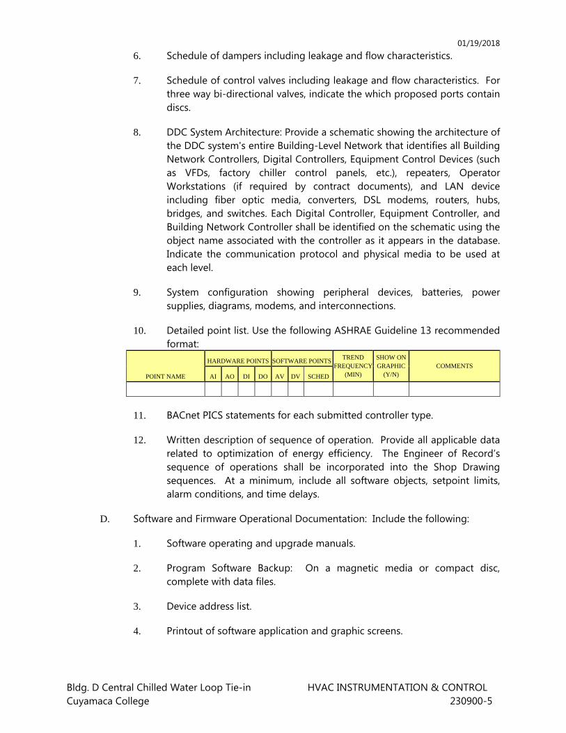
01/19/2018
Bldg. D Central Chilled Water Loop Tie-in HVAC INSTRUMENTATION & CONTROL Cuyamaca College 230900-5
6. Schedule of dampers including leakage and flow characteristics.
7. Schedule of control valves including leakage and flow characteristics. For three way bi-directional valves, indicate the which proposed ports contain discs.
8. DDC System Architecture: Provide a schematic showing the architecture of the DDC system's entire Building-Level Network that identifies all Building Network Controllers, Digital Controllers, Equipment Control Devices (such as VFDs, factory chiller control panels, etc.), repeaters, Operator Workstations (if required by contract documents), and LAN device including fiber optic media, converters, DSL modems, routers, hubs, bridges, and switches. Each Digital Controller, Equipment Controller, and Building Network Controller shall be identified on the schematic using the object name associated with the controller as it appears in the database. Indicate the communication protocol and physical media to be used at each level.
9. System configuration showing peripheral devices, batteries, power supplies, diagrams, modems, and interconnections.
10. Detailed point list. Use the following ASHRAE Guideline 13 recommended format:
POINT NAME
HARDWARE POINTS SOFTWARE POINTSTREND
FREQUENCY (MIN)
SHOW ON GRAPHIC
(Y/N) COMMENTS
AI AO DI DO AV DV SCHED
11. BACnet PICS statements for each submitted controller type.
12. Written description of sequence of operation. Provide all applicable data related to optimization of energy efficiency. The Engineer of Record’s sequence of operations shall be incorporated into the Shop Drawing sequences. At a minimum, include all software objects, setpoint limits, alarm conditions, and time delays.
D. Software and Firmware Operational Documentation: Include the following:
1. Software operating and upgrade manuals.
2. Program Software Backup: On a magnetic media or compact disc, complete with data files.
3. Device address list.
4. Printout of software application and graphic screens.
01/19/2018
Bldg. D Central Chilled Water Loop Tie-in HVAC INSTRUMENTATION & CONTROL Cuyamaca College 230900-6
5. Software license required by and installed for DDC workstations and control systems.
6. Domain, Subnet, & Channel ID’s.
E. Software Upgrade Kit: For Owner to use in modifying software to suit future system revisions or monitoring and control revisions.
F. Test Plan for Contractor Field Tests
1. For every Network Building Controller and Digital Controller provide a Field Test Checkout Sheet. All data that can be filled out on each checkout sheet prior to conducting the test, shall be provided on each sheet.
2. Include the intended test procedure, the expected response, and the pass/fail criteria for every component tested.
G. Functional Performance Testing Plan
1. Provide a written description of a set of step-by-step test procedures that shall be performed by the DDC contractor to demonstrate the functionality of every aspect of the sequences of operation. The PVT test plan shall be a clear list of test items arranged in a logical sequence.
2. The plan shall clearly describe how each item is tested, indicating where assisting personnel are required (like the mechanical contractor), and include what procedures are used to simulate conditions.
H. Field Test Reports: Indicate and interpret test results for compliance with performance requirements.
I. Maintenance Data: For systems to include in maintenance manuals specified in Division 1. Include the following:
1. Maintenance instructions and lists of spare parts for each type of control device.
2. Interconnection wiring diagrams with identified and numbered system components and devices.
3. Keyboard illustrations and step-by-step procedures indexed for each operator function.
4. Inspection period, cleaning methods, cleaning materials recommended, and calibration tolerances.
5. Calibration records and list of set points.
01/19/2018
Bldg. D Central Chilled Water Loop Tie-in HVAC INSTRUMENTATION & CONTROL Cuyamaca College 230900-7
J. Project Record Documents: Record actual locations of control components, including control units, thermostats, and sensors. Revise Shop Drawings to reflect actual installation and operating sequences. Provide an updated floor plan indication the actual installed location of room temperature sensors and duct static pressure sensors.
K. Seventy-two (72) hour trend data.
L. HVAC Instrumentation and Controls training program.
1.8 QUALITY ASSURANCE
A. Installing Company Qualifications:
1. Five years of experience in installation of similar systems for similar projects.
2. Experience in completing a minimum of three local projects of similar size with the type of DDC system specified for this project within the last five years.
3. A Building Automation Service Department within the project site with a 2-hour minimum response time for emergency service.
4. Authorized Factory Representative for submitted BACnet controls product.
B. Manufacturer Qualifications: A firm experienced in manufacturing automatic temperature-control systems and with a record of successful in-service performance. The manufacturer’s DDC control hardware and software shall have BACnet conformance approval from the BACnet Test Laboratory. The control system architecture shall consist of the components of one manufacturer regularly engaged in the production of open control systems and shall be the manufacturer’s latest standard of design at the time of the bid.
C. Control Engineer Qualifications: A control Engineer shall oversee the design and installation of the DDC system. The Control Engineer shall have a minimum of five (5) years experience with the installing company at an equal level of responsibility. The Control Engineer shall have completed factory training for certification for the design, installation, start-up, and commissioning of the DDC components to be installed. The Control Engineer shall have experience in completing a minimum of two projects of similar size with the type of DDC system specified for this project. Removal or replacement of Control Engineer shall be subject to the owner’s approval.
D. Electrical Components, Devices, and Accessories: Listed and labeled as defined in NFPA 70, Article 100, by a testing agency acceptable to authorities having
01/19/2018
Bldg. D Central Chilled Water Loop Tie-in HVAC INSTRUMENTATION & CONTROL Cuyamaca College 230900-8
jurisdiction, and marked for intended use. All DDC controllers for this project shall be manufactured by single manufacturer. A mixture of DDC controllers by various manufacturers shall not be allowed. All DDC controllers, building controllers and application controllers shall communicate via BACnet LAN.
E. Comply with NFPA 90A, "Installation of Air Conditioning and Ventilation Systems."
F. Comply with ASHRAE 135 for DDC system control components.
G. Control panels and cabinets installed in this project shall be UL 508A listed as a complete assembly. All electronic components and devices shall be enclosed in NEMA rated enclosures.
H. All system levels shall be compliant with the BACnet Standard 135-2008. Upon completion of commissioning process and prior to acceptance, contractor shall provide a protocol analyzer and demonstrate that all system components that communicate within the system utilize the BACnet protocol. Contractor may at their expense hire a qualified, independently registered engineer to perform test. Any components that do not fully comply with the BACnet standard shall be replaced until entire system architecture is re-tested and compliant. Conflict resolution shall be submitted to BTL (www.BACnetassociation.org) at contractor’s expense and BTL determination shall be final.
1.9 DELIVERY, STORAGE, AND HANDLING
A. Factory-Mounted Components: Where control devices specified in this Section are indicated to be factory mounted on equipment, arrange for shipping of control devices to unit manufacturer.
1.10 COORDINATION
A. Coordinate location of room temperature sensors, and other exposed control sensors with plans and room details before installation.
B. Coordinate supply of conditioned electrical circuits for control units and operator workstation.
C. Coordinate chiller control network requirements with chiller control requirements and control system components provided with the chiller equipment.
D. Coordinate equipment to achieve compatibility with motor starters and annunciation devices.
E. Coordinate with Division 26 for Electrical Power Supply to Control Equipment and Device. Unless otherwise specified under Division 26, provide and install all the
01/19/2018
Bldg. D Central Chilled Water Loop Tie-in HVAC INSTRUMENTATION & CONTROL Cuyamaca College 230900-9
electrical wiring/conduit and components for a complete and operational control system.
1.11 WARRANTY
A. The system shall include all hardware and software components warranty for a period of one year following the substantial completion date. Provide a five-year warranty for all actuators and valves.
PART 2 - PRODUCTS
2.1 MANUFACTURERS
A. Manufacturer: Subject to compliance with requirements, installing company qualifications, and manufacturer’s qualifications, provide products by the following. The manufacturer shall provide DDC control hardware and software with BACnet conformance approvals from the BACnet Test Laboratory.
1. Electric, Electronic, and DDC Systems:
a. Alerton, Ascent Compass for BACtalk
b. No Substitutions Allowed.
2.2 DDC EQUIPMENT AND SOFTWARE
A. Graphics-Based Software: The intent of graphic-based software is to provide an ergonomic interface to the DDC system that encourages effective and efficient interaction with the system. Graphic-based software shall provide graphical representation of the building, the buildings mechanical systems, and the DDC system. The current value and point name of every I/O point shall be shown on at least one graphic and in its appropriate physical location relative to building and mechanical systems.
1. Graphics shall closely follow the style of the control drawings in representing mechanical systems, sensors, controlled devices, and point names.
2. Graphic Title: Graphics shall have an identifying title visible when the graphic is being viewed.
3. Dynamic Update: When the workstation is on-line with the control system, point data shall update dynamically on the graphic images.
4. Graphic Penetration: Provide graphic penetration for selection of individual graphics for hierarchical affect.
01/19/2018
Bldg. D Central Chilled Water Loop Tie-in HVAC INSTRUMENTATION & CONTROL Cuyamaca College 230900-10
5. Graphic Types: Graphic-based software shall have graphics of the building exterior, building section, floor plans, and mechanical systems. Provide the following graphics.
a. Building Exterior Graphic: Show exterior architecture, major landmarks, and building number.
b. Building Section Graphic: Show stacked floors in section graphic with appropriate floor name on each floor.
c. Floor Plan Graphics: Provide single graphic for each floor, unless the graphic will contain more information than can reasonably be shown on a single graphic. Each heating or cooling zone within a floor plan shall have a zone name and its current temperature displayed within the zone outline. Show each controlled variable in the zone. Provide visual indication for each point that is in alarm.
d. Mechanical System Graphic: Provide two-dimensional drawings to symbolize mechanical equipment; do not use line drawings. Show controlled or sensed mechanical equipment. Each graphic shall consist of a single mechanical system; examples are a graphic for an air handling unit, a graphic for VAV box, a graphic for a heating water system, and a graphic for chiller system. Place sensors and controlled devices associated with mechanical equipment in their appropriate locations. Place point name and point value adjacent to sensor or controlled device. Provide visual indication of each point in alarm. Condition, such as zone temperature, associated with the mechanical system shall be shown on the graphic. Point values shall update dynamically on the graphic.
6. Graphic Editing: Full capacity as afforded by a draw software package shall be included for operator editing of graphics. Graphics may be created, deleted, and modified, and text added. Provide capability to store graphic symbols in a symbol directory and incorporate these symbols into graphics. A minimum of sixteen colors shall be available.
7. Dynamic Point Editing: Provide full editing capability for deleting, adding, and modifying dynamic points on graphics.
8. Trending: Trend data shall be displayed graphically, with control variable and process variable plotted as functions of time on the same chart. Graphic display of trend data shall be a capability internal to the workstation software and not a capability resulting from download of trend data into a third-party spreadsheet program such as Lotus, unless such transfer is automatic and transparent to the operator, and third-
01/19/2018
Bldg. D Central Chilled Water Loop Tie-in HVAC INSTRUMENTATION & CONTROL Cuyamaca College 230900-11
party software is included with the workstation software package. At the operator’s discretion trend data shall be plotted real time.
9. Program Editing: Provide full editing capability for deleting, adding, and modifying DDC programs from the graphical workstation and upload/download capability to the field panels.
B. Server and Operator Workstation
1. Controls Server: The provided controls shall be integrated into the existing Alerton Ascent Compass network server software by the contractor.
2. Graphics software: The graphics on the existing Alerton graphical user interface shall be modified to incorporate the additional sequences and equipment identififed.
C. DDC Controllers
1. Provide Alerton BACtalk controllers per the District’s designated brands agreement for existing buildings.
2. Communication among DDC Controllers shall be via BACnet MSTP. Building controller shall incorporate as a minimum, the functions of a 3-way BACnet router. Controller shall route BACnet messages between the high-speed LAN (Ethernet 10/100MHz), master slave token passing (MS/TP) LANs, a point-to-point (PTP – RS-232) connection and modem.
3. Each MS/TP LAN shall be software configurable from 9.6 to 76.8Kbps.
4. Building controller shall be capable of providing global control strategies for the system based on information from any objects in the system regardless if the object is directly monitored by the controller or by another controller. The program that implements these strategies shall be completely flexible and user definable.
5. Programming shall be object-oriented using control function blocks, supporting DDC functions, 1000 Analog Values and 1000 Binary Values. All flowcharts shall be generated and automatically downloaded to controller. Programming tool shall be resident on workstation and the same tool used for all controllers.
6. Provide means to graphically view inputs and outputs to each program block in real-time as program is executing. This function may be performed via the operator’s workstation or field computer.
01/19/2018
Bldg. D Central Chilled Water Loop Tie-in HVAC INSTRUMENTATION & CONTROL Cuyamaca College 230900-12
7. Building controller shall provide battery-backed real-time (hardware) clock functions.
8. Controller shall have a memory needed to ensure high performance and data reliability. Battery shall retain static RAM memory and real-time clock functions for a minimum of 2 years (cumulative).
9. Building Controllers and Custom Application Controllers shall be selected to provide a minimum of 15% spare I/O point capacity for each point type found at each location. If input points are not universal, 15% of each type is required. If outputs are not universal, 15% of each type is required. A minimum of one spare is required for each type of point used.
a. Future use of spare capacity shall require providing the field device, field wiring, point database definition, and custom software. No additional controller boards or point modules shall be required to implement use of these spare points.
10. Provide sufficient internal memory for the specified sequences of operation and trend logging. There shall be a minimum of 25% of available memory free for future use.
11. Building controller shall provide battery-backed real-time (hardware) clock functions.
12. Controller shall have the memory needed to ensure high performance and data reliability. Battery shall retain static RAM memory and real-time clock functions for a minimum of 2 years (cumulative). The controller shall maintain all BIOS and programming information in the event of a power loss for at least 72 hours. Protect programs residing in memory with EEPROM or flash memory. Building Network Controllers shall store all trends and alarms in flash memory and automatically perform a safe system shutdown preserving all data upon a line power outage. Building Network Controllers shall have a rechargeable battery with sufficient capacity to perform the safe system shutdown.
13. Rechargeable power sources shall be constantly charged while the controller is operating under normal line power. Batteries shall be replaceable without soldering.
D. Application-Specific controllers:
1. Provide one native BACnet application specific controller for each piece of unitary mechanical equipment that adequately covers all objects listed. All controllers shall interface to building controller via MS/TP LAN using BACnet protocol. Controllers shall include input, output and self-contained logic program as needed for complete control of unit.
01/19/2018
Bldg. D Central Chilled Water Loop Tie-in HVAC INSTRUMENTATION & CONTROL Cuyamaca College 230900-13
2. Zone damper: Actuators shall be electronic with a means for lockable manual override.
3. Provide a metal NEMA 2 enclosure for actuator assembly of the zone controllers.
4. Provide a metal NEMA 2 enclosure for all electronic components of zone controller.
E. Software Capabilities: Update to latest version of software at Project completion. Include and implement the following capabilities from the control units:
1. Units of Measure: Inch-pound and SI (metric).
2. Load Control Programs: Demand limiting, duty cycling, automatic time scheduling, start/stop time optimization, night setback/setup, DDC with fine tuning, and trend logging.
3. HVAC Control Programs: Optimal run time, supply-air reset, and enthalpy switchover.
4. Programming Application Features: Include trend point, alarm messages, weekly scheduling, and interlocking.
5. Paging: Provide the means of automatic alpha numeric paging of personnel for user defined control system requirements.
2.3 CONTROL PANELS
A. Control Panels: Unitized cabinet with suitable brackets for wall or floor mounting, located adjacent to each system under automatic control. Provide common keying for all panels. Provide UL 508A listed panels as a complete assembly.
1. Fabricate panels of 0.06-inch- thick, furniture-quality steel, or extruded-aluminum alloy, totally enclosed, with hinged doors and keyed lock and with manufacturer's standard shop-painted finish.
2. Panel-Mounted Equipment: Temperature and humidity controllers, relays, and automatic switches; except safety devices. Mount devices with adjustments accessible through front of panel.
3. Door-Mounted Equipment: Flush-mount (on hinged door) manual switches, including damper-positioning switches, changeover switches, thermometers, and gages.
4. Graphics: Color-coded graphic, laminated-plastic displays on doors, schematically showing system being controlled, with protective, clear plastic sheet bonded to entire door.
01/19/2018
Bldg. D Central Chilled Water Loop Tie-in HVAC INSTRUMENTATION & CONTROL Cuyamaca College 230900-14
5. Provide one uninterruptable power supply for each supervisory control panel.
B. Alarm Panels: Indicating light for each alarm point, single horn, acknowledge switch, and test switch, mounted in hinged-cover enclosure.
1. Alarm Condition: Indicating light flashes and horn sounds.
2. Acknowledge Switch: Horn is silent and indicating light is steady.
3. Second Alarm: Horn sounds and indicating light is steady.
4. Alarm Condition Cleared: System is reset and indicating light is extinguished.
5. Contacts in alarm panel allow remote monitoring by independent alarm company.
C. Provide one external Uninterrupted Power Supply (UPS) in NEMA 1 enclosure for every DDC Control Panel. Enclosures on the roof shall be NEMA 12R.
2.4 SENSORS AND COMMUNICATION DEVICES
A. Electronic Sensors: Vibration and corrosion resistant; for wall, immersion, or duct mounting as required.
1. Current Sensing Relays: Solid State AC switch with internal current transformer. The switch shall operate when the current level sensed by the internal current transformer exceeds the threshold value set by the adjustment knob. Provide relays with split core design for the range suitable for application. Coordinate with electrical contractor.
2. Current Transformer: Provide current transformers rated for the specified amperage. The transformer shall provide 0 to 5 VDC output signal.
3. Electrical Valve/Damper Position Indication: Visual scale indicating percent of travel and 2- to 10-V dc feedback signal.
4. Gateways and Direct LAN Connections: Coordinate with HVAC equipment manufacturers, provide and install a complete and operational control Gateway and or Direct LAN connection to the HVAC equipment. Coordinate with equipment manufacturers and other trades to avoid omission or duplication and assure a complete and operating system.
B. Switches and sensors applications:
1. Chilled Water Pipe Temperature Sensors: 1000 Ohm RTD Liquid Immersion Sensors with operating range 20 degrees F to 70 degrees F.
01/19/2018
Bldg. D Central Chilled Water Loop Tie-in HVAC INSTRUMENTATION & CONTROL Cuyamaca College 230900-15
2. Provide and install all other components indicated for complete and operational system.
2.5 ACTUATORS
A. Electronic Damper, Large-Valve Actuators: Direct-coupled type designed for minimum 60,000 full-stroke cycles at rated torque.
1. Valves: Size for torque required for valve close-off at maximum pump differential pressure.
2. Dampers: Size for running torque calculated as follows:
3. Opposed-Blade Damper with Edge Seals: 5 inch-pounds/sq. ft. of damper.
4. Pressure Drop: Dampers with 2 to 3 Inches wg of Pressure Drop.
a. Coupling: V-bolt and V-shaped, toothed cradle.
b. Overload Protection: Electronic overload or digital rotation-sensing circuitry.
c. Fail-Safe Operation: Mechanical, spring-return mechanism. Provide external, manual gear release on non-spring-return actuators.
d. Power Requirements (Modulating): Maximum 10 VA at 24-V ac or 8 W at 24-V dc.
e. Proportional Signal: 2- to 10-V dc or 4 to 20 mA, and 2- to 10-V dc position feedback signal.
f. Temperature Rating: 40 to 104 deg F.
g. Temperature Rating (Smoke Dampers): Minus 22 to plus 250 deg F.
h. Run Time: 12 seconds open, 5 seconds closed.
2.6 BI-DIRECTIONAL THREE WAY CONTROL VALVE
A. Commercial-Grade Butterfly Valves NPS 2 through NPS 6:
1. Application: Two position control valves for service switchover.
2. Manufacturer Belimo HDX or approved equal.
3. Three-way valve arrangement: Two 2-way butterfly valves in a cast iron Tee configuration cross-linked to ensure proper flow orientation.
01/19/2018
Bldg. D Central Chilled Water Loop Tie-in HVAC INSTRUMENTATION & CONTROL Cuyamaca College 230900-16
4. Performance:
a. Bi-directional 0% shut-off at 200 psig.
b. Bubble-tight shutoff (no leakage).
c. Rotation: Zero to 90 degrees.
d. Modified equal percentage flow characteristic.
5. Body: Ductile iron fully lugged 200 psig body.
6. Disc: 304 stainless steel with a pin connection. A coated disc shell is not acceptable.
7. Shaft: 304 stainless steel.
8. Seat: Reinforced EPDM.
9. Shaft Bushings: Reinforced PTFE supported at a minimum of 4 locations.
10. Process temperature rating: negative 22 Deg F to plus 250 Deg F.
11. Actuators:
a. Overload Protection: Auto-reset thermal switch shall be embedded in the motor.
b. Actuator shall be equipped with a hand wheel or shaft for manual override to permit operation of the actuator in the event of an electrical power failure.
c. A visual indication beacon shall indicate position status of the device.
12. Corrosion-resistant nameplate indicating:
a. Model number and production date.
b. Body size.
c. Flow arrow.
13. The valve assembly shall include a reflective position indicator.
14. The travel rotation shall be automatically be determined by the actuator without the use of adjustable mechanical cams or end of travel limit switches. End of travel limit switches are not acceptable.
15. Actuator shall self-adapt to ensure close-off with no end stop limit adjustment required. End of travel limit switches are not acceptable.
01/19/2018
Bldg. D Central Chilled Water Loop Tie-in HVAC INSTRUMENTATION & CONTROL Cuyamaca College 230900-17
16. Override: A detachable hand crank shall also de-clutch the actuator to permit manual override when powered.
17. Proportional actuators shall be software configurable through an EEPROM without the use of actuator mounted switches. Programmable functions shall include a scalable operating range 0.5 – 32.0 vdc with a 2.0 vdc (minimum) span; variable runtime; and data logging. BACnet communication shall be included.
2.7 TWO WAY GLOBE VALVES:
1. Application: Modulating control valves up 8” for chilled water, heating hot water, and condenser water applications.
2. Valve Sizing: 3-6 psig pressure drop at design flow rate.
3. Single Seated (Two-way) Valves: Valves shall have equal-percentage characteristic for typical heat exchanger service and linear characteristic for building loop connections to campus systems unless otherwise scheduled on the drawings. Valves shall have cage-type trim, providing seating and guiding surfaces for plug on ‘top-and-bottom’ guided plugs.
4. Double Seated (Three-way) Valves: Valves shall have linear characteristics. Valves shall be balanced-plug type, with cage-type trim providing seating and guiding surfaces on ‘top-and-bottom’ guided plugs.
5. Temperature Rating: 25 degrees F minimum, 250 degrees F maximum
6. Body: Bronze, screwed, 250 psi maximum working pressure for ½ inch to 2 inch; Cast iron, flanged, 125 psi maximum working pressure for 2-1/2 inches and larger.
7. Valve Trim: Bronze; Stem: Polished stainless steel
8. Packing: Spring Loaded Teflon or Synthetic Elastomer U-cups, self-adjusting
9. Plug: Brass, bronze or stainless steel, Seat: Brass
10. Disc: Replaceable composition or stainless steel filled PTFE
11. Ambient Operating Temperature Limits: -10 to 150 degrees F (-12.2 to 66 degrees C)
01/19/2018
Bldg. D Central Chilled Water Loop Tie-in HVAC INSTRUMENTATION & CONTROL Cuyamaca College 230900-18
12. Acceptable Manufacturers: Subject to compliance with requirements, approved manufacturers are as follows:
a. Honeywell
b. Belimo
c. Approved equal
2.8 CONTROL CABLE
A. Fiber Cable and Termination Hardware
1. Cables: Comply with UL and CEC requirements.
B. Twisted Pair Cabling
1. Cables: Comply with ANSI EIA/TIA-568-B standard, ICEA specifications, UL and CEC requirements.
2. Install control wiring in conduit except as specified under Part 3 of this section.
PART 3 - EXECUTION
3.1 EXAMINATION
A. Verify that conditioned power supply is available to control units and operator workstation.
B. Verify that duct, pipe, and equipment-mounted devices and wiring and piping are installed before proceeding with installation.
C. Obtain the manufacturer data for the proposed HVAC equipment. Verify the electric power supply requirements of control interfaces and connections. Coordinate with electrical and mechanical contractors and other trades.
3.2 INSTALLATION
A. Install DDC Controllers for a complete and operational system. Install all DDC controllers inside NEMA rated control panels.
B. Install in accordance with manufacturer's instructions.
C. Install control wiring and electrical work in accordance with National Electrical codes. In addition to the requirements specified herein, the wiring installation shall meet the requirements of EIA/TIA Standard 568, Commercial Building Standard for telecommunication pathways and spaces.
01/19/2018
Bldg. D Central Chilled Water Loop Tie-in HVAC INSTRUMENTATION & CONTROL Cuyamaca College 230900-19
D. Wiring Inside Rigid Conduit: Outdoor exposed areas and areas exposed to weather. Minimum conduit size 3/4".
E. Plenum Rated Wiring: Concealed areas above ceilings. Coordinate with electrical contractor. Support final connection wiring in accordance to National Electric Code and at every four feet. Diagonal installation shall not be accepted. Provide sleeves for wall penetrations.
F. Identification Standards:
1. Node Identification: All nodes shall be identified by a permanent label fastened to the outside of the enclosure.
2. Cable shall be labeled at a minimum of every 18” with the type of signal carried within the cable.
3. Raceway Identification: All the covers to junction and pull boxes of the control raceways shall be painted with the appropriate color.
4. Wire Identification: All low and line voltage control wiring shall be identified by a number, as referenced to the associated shop drawing and as-built drawing.
5. Control wiring color coding shall be consistent throughout this project. Coordinate with the owner and other trades. Provide communication and control wiring with proper identification and labeling. Clearly label and color code control wiring as follows:
a. Orange: Local area network wiring.
b. Blue: Analog and digital, input or output points.
c. Green: Low voltage power wiring.
d. White: Line voltage wiring, or per National Electric Codes.
G. Do not install low and line voltage wiring in the same conduit.
H. Provide and install wiring and conduit in connection with HVAC instrumentation and controls for complete operational system.
I. Provide and install electrical power supply to HVAC instrumentation and controls unless otherwise specified under Division 26. Coordinate with Division 26.
J. Install transformers inside NEMA rated control enclosures.
K. Label all control components and instruments.
01/19/2018
Bldg. D Central Chilled Water Loop Tie-in HVAC INSTRUMENTATION & CONTROL Cuyamaca College 230900-20
L. Verify the actual location of room temperature sensors prior to installation. Coordinate with furniture layout. Assure the location of each room temperature sensor is within the zone of the corresponding HVAC equipment. Verify that the room sensor locations provides an acceptable measurement of the controlled environment. Comply with ADA requirements.
M. Perform and document comprehensive testing for all control installation. Provide necessary instruments and equipment to document the results.
1. Verify that circuits are continuous and free from short circuits and grounds.
2. Verify that circuits are free from unspecified ground. The resistance to ground of all circuits shall be over 50 megaOhms.
3. Verify that circuits are free from induced voltage.
4. Provide complete testing for all cables used under this contract. Provide all equipment, tools, and personnel as necessary to conduct these tests.
5. Provide for complete grounding of all signal and communication cables, panels, and equipment so as to ensure system integrity of operation. Ground cabling and conduit at the panel terminations. Avoid grounding loops.
N. Installation Quality Requirements: In addition to the requirements of Division 26, manufacturer’s recommendation and National Electric Codes, provide installation quality requirements specified here for a complete and operational control system.
1. All conduits and raceways shall be installed level, plumb, at right angles to the building lines and shall follow the contours of the surface to which they are attached.
2. Flexible Metal Conduit shall be used for vibration isolation and shall be limited to 3 feet in length when terminating to vibrating equipment. Flexible Metal Conduit may be used within partition walls. Flexible Metal Conduit shall be UL listed.
3. Provide firestopping for all penetrations.
4. All openings in fire proofed or fire stopped components shall be closed by using approved fire resistive sealant.
5. All wiring passing through penetrations, including walls, shall be in conduit or enclosed raceway.
01/19/2018
Bldg. D Central Chilled Water Loop Tie-in HVAC INSTRUMENTATION & CONTROL Cuyamaca College 230900-21
6. Penetrations of floor slabs shall be by core drilling. All penetrations shall be plumb, true, and square.
7. No penetrations in structural elements shall be made before receipt of written approval from the architect.
3.3 DATABASE BACKUP AND STORAGE
A. The DDC system shall be configured to automatically backup its database at regular intervals. The database shall be backed up based on a user-defined time interval.
B. Copies of the current database and, at the most recently saved database shall be stored in the server. The age of the most recently saved database is dependent on the user-defined database save interval.
3.4 HVAC INSTRUMENTATION AND CONTROLS TRAINING PROGRAM
A. Develop a comprehensive effective training program. Submit for approval.
B. Field Training of Operators: In addition to other training requirements specified elsewhere, upon completion of work under this section and upon owner’s acceptance provide 8 hours of formal classroom training for owners operators. The training shall be conducted by factory trained control engineers and technicians. A factory certified trainer shall be present during the training. Provide handouts and audio visual programs as required.
3.5 COMMISSIONING OF BUILDING AUTOMATION SYSTEM
A. Commissioning per ASHRAE Standards. Commissioning Report shall include the following:
1. Seventy-two (72) hour Trend Data.
2. Installation Verification of Building Automation System.
B. Refer to Mechanical Commissioning Section. Coordinate and provide the required expertise and services for a complete commissioning process. Coordinate with all other trades for a complete commissioned system. Coordinate with the commissioning authority.
C. Documents results in Standard Forms recommended by DDC manufacturer or other established organizations. Comply with the similar standards established by AABC, NEBB or ASHRAE. Obtain approval prior to commencement of the work.
D. Attend the monthly commissioning meeting. Coordinate with the commissioning authority of the project.
01/19/2018
Bldg. D Central Chilled Water Loop Tie-in HVAC INSTRUMENTATION & CONTROL Cuyamaca College 230900-22
E. Provide seasonal simulation to allow for a complete and operating system throughout the year. Provide a comprehensive building automation re-commissioning within 6 months of installation for seasonal adjustment.
F. The Control Contractor’s Engineer shall be present on-site for all commissioning activities involving equipment and systems controlled and monitored by the DDC system. In addition, provide no less than 45 working days for on-site support during the functional performance test.
3.6 SEVENTY-TWO (72) HOUR TREND DATA
A. Upon completion after project provide a seventy-two (72) hour data indicating complete operation of DDC System. Final acceptance of the completion of the DDC shall be based upon the seventy-two (72) hour Trend Data. The Trend Data shall be in form of color Trend Graph. Provide Trend Data of all temperatures, air- and water- flow quantities, and equipment status points. This shall include room, outside air, chilled water, heating hot water, condensing water temperatures and set points. Trend data shall also include duct and pipe pressures and set points. The trend data shall also include variable frequency drive speed and frequency. It shall also include outside, return and supply air quantities and position of dampers. Provide trend data for kW meter and chiller operation. Submit specified list of points and graphic format of trending for approval prior to commencement of 72-hour trending. Coordinate with commissioning agent.
B. Provide additional (72) hour trend data as required until full compliance.
C. A factory-trained control technician with minimum of 3 years experience shall be physically present at the jobsite from 8:00 am to 5:00 pm during every 72 hour trending process until final acceptance.
D. Upon completion submit the results indicating compliance in one complete package. Submit 6 sets.
3.7 INSTALLATION VERIFICATION OF BUILDING AUTOMATION SYSTEM
A. Controller Verification: Perform verification procedure on each DDC controller prior to software installation and prior to commencement of point to point check-out.
B. Verify installation of labels and nameplates to identify control components according to Division 23.
C. Verify installation of hydronic instrument wells, valves, and other accessories according to Division 23.
01/19/2018
Bldg. D Central Chilled Water Loop Tie-in HVAC INSTRUMENTATION & CONTROL Cuyamaca College 230900-23
D. Document results in Standard Forms recommended by DDC manufacturer or other established organizations. Comply with similar standards established by NEBB or ASHRAE. Obtain approval prior to commencement of the work.
E. Upon completion submit the results indicating compliance.
3.8 FIELD QUALITY CONTROL
A. Manufacturer's Field Service: Engage a factory-authorized service representative to inspect field-assembled components and equipment installation, including piping and electrical connections. Report results in writing.
1. Operational Test: After electrical circuitry has been energized, start units to confirm proper unit operation. Remove malfunctioning units, replace with new units, and retest.
2. Test and adjust controls and safeties. Replace damaged and malfunctioning controls and equipment, and retest.
3. Calibration test electronic controllers by disconnecting input sensors and stimulating operation with compatible signal generator.
B. Engage a factory-authorized service representative to perform startup service.
C. Replace damaged or malfunctioning controls and equipment.
1. Start, test, and adjust control systems.
2. Demonstrate compliance with requirements, including calibration and testing, and control sequences.
3. Adjust, calibrate, and fine tune circuits and equipment to achieve sequence of operation specified.
D. Verify DDC as follows:
1. Verify software including automatic restart, control sequences, scheduling, reset controls, and occupied/unoccupied cycles.
2. Verify operation of operator workstation.
3. Verify local control units including self-diagnostics.
3.9 DEMONSTRATION
A. Engage a factory-authorized service representative to train Owner's maintenance personnel to adjust, operate, and maintain control systems and components.
01/19/2018
Bldg. D Central Chilled Water Loop Tie-in HVAC INSTRUMENTATION & CONTROL Cuyamaca College 230900-24
1. Train Owner's maintenance personnel on procedures and schedules for starting and stopping, troubleshooting, servicing, and maintaining equipment and schedules.
2. Provide operator training on data display, alarm and status descriptors, requesting data, executing commands, calibrating and adjusting devices, resetting default values, and requesting logs. In addition to training requirements specified elsewhere, include a minimum of 32 hours' dedicated factory instructor time on-site.
3. Review data in maintenance manuals. Refer to Division 1 Section "Contract Closeout."
4. Review data in maintenance manuals. Refer to Division 1 Section "Operation and Maintenance Data."
5. Schedule training with Owner, through Architect, with at least seven days' advance notice.
END OF SECTION
01/19/2018
Bldg. D Central Chilled Water Loop Tie-in HVAC SEQUENCE OF OPERATION Cuyamaca College 230993 - 1
SECTION 230993 – HVAC SEQUENCE OF OPERATIONS
PART 1 - GENERAL
1.1 Related Documents
A. Drawings and general provisions of the Contract, including General and Supplementary Conditions and Division 1 Specification Sections, apply to this Section.
1.2 Summary
A. This Section includes control sequences for HVAC systems, subsystems, and equipment.
B. Related Sections include the following:
C. Division 23 Section "HVAC Instrumentation and Controls" for control equipment and devices and submittal requirements.
1.3 Definitions
A. DDC: Direct-digital controls.
B. VFD: Variable Frequency Drive
C. CHW: Chilled Water
1.4 General
A. Equipment start stop and Software Interlocks
1. Mechanical equipment shall be operated, controlled and monitored by the DDC system using the input/output (I/O) shown on the drawings. The operation of the equipment shall be subject to the operational modes, conditions and logic described in this Section. A time delay shall be initiated on system command for equipment start to allow status feedback devices to actuate. At the expiration of the time delay, absence of the run status input signal, which indicates a failure to start or to continue to run, shall cause the system to alarm and start standby units as required. The system shall not restart until commanded to “return to normal”. Alarms assigned to analog inputs shall be delayed on equipment startup to allow sufficient time for equipment capacity to bring the process variable values within the normal range. Variable capacity pumps shall always start in an “unloaded” condition.

01/19/2018
Bldg. D Central Chilled Water Loop Tie-in HVAC SEQUENCE OF OPERATION Cuyamaca College 230993 - 2
2. HAND-OFF-AUTO switches shall be monitored to generate a critical alarm (an alarm that must be acknowledged) when the switch is indexed out of the “AUTO” position.
3. Whenever equipment is put into operation automatically, the DDC control loops shall be activated. When equipment is not operating, control loops shall be deactivated and end elements shall go to their normally open or normally closed positions as shown on the contract drawings unless otherwise specified.
B. Electric Hardwire Interlocks
1. Electric hardwire interlocks shall be as shown on the drawings and as required for chiller system shutdown from activation of a refrigerant leak detector.
C. Control of Valve Speed
1. The DDC system shall apply P, PI or PID control by modulating analog outputs to the actuators in the proper direction to control temperature, pressure, flow and other process variables as specified.
2. All control and alarm setpoints shall be adjustable by the operator. Initial setting of all control and alarm setpoints shall be performed by the DDC system Contractor.
3. Isolation valve actuation speeds shall be adjusted per the chiller manufacturer’s recommendations and to avoid nuisance tripping of operating chillers.
D. DDC System Failure
1. If Remote Control Panels (RCPs or ACPs) should fail, the operating equipment controlled by that panel shall continue to function, based on the last command.
1.5 Chilled Water System Control
A. The CHW system will be enabled based on a time-of-day (TOD) schedule and system demand as indicated by CHW valve positions or as programmed by the building operator. System operation shall be allowed at all times.
B. The DDC system shall continue to interface with the Bldg D and Central Plant chiller control system to enable/disable the chillers, provide temperature setpoint reset signal, and monitor chiller run status and alarms based on existing sequence of operation. The existing plant operations sequences shall not be altered.
C. The central and Building D chilled water plant shall follow its originally programed start-up sequence when commanded on.
01/19/2018
Bldg. D Central Chilled Water Loop Tie-in HVAC SEQUENCE OF OPERATION Cuyamaca College 230993 - 3
D. The contractor shall program the following three modes for plant operation:
1. Mode 1 – Operating Building D with the Building D chiller : The central plant chilled water feed shall be isolated during this mode and Building D’s chilled water plant shall operate per its current sequence of operation.
2. Mode 2 - Operating Bldg. D with the Central CHW Plant : The Building D cooling demand is satisfied by the central chilled water plant. The Building D chiller and cooling tower shall be isolated through the three-way valves and shall be disabled during this mode. The Building D constant speed chilled water pumps shall serve as tertiary pumps and will continue to operate during this mode to satisfy the cooling demand.
The supply and return chilled water temperature to the campus shall be monitored and the chilled water return control valve shall modulate to maintain a minimum of 14 degrees F (adjustable) between supply and return water temperature only in this mode.
The Building D chilled water pumps shall be commanded off and the central plant chilled water isolation valves (V-1 and V-5) shall be closed when there is no demand for cooling in Building D.
Mode 2 shall be the default operating mode during weekdays.
3. Mode 3 - Operating Campus Loop with Bldg. D CHW Plant : If the central chilled water plant is enabled during weekend, holiday, or overnight periods, Bldg D’s CHW plant shall be enabled as the primary source of cooling.
a. Disable Central Chilled Water Plant equipment during this mode.
b. Command control valves open/closed per the table below. Valve speed shall be per the manufacturers recommendations and as required to eliminate hydraulic shock.
c. The booster pumps in buildings calling for cooling shall be enabled.
d. Staging: if the supply air temperature of any enabled air handling unit rises more than 3 deg F above setpoint during Mode 3 for more than 15 minutes (adjustable) after an initial 60 minute (adjustable) loop cool-down period, disable Mode 3 and enable the Central Plant.
Provide a push button graphic on the main DDC graphics page indicating current operating mode. All the operator to override the Mode selection manually through this feature for a user-selected time period.
01/19/2018
Bldg. D Central Chilled Water Loop Tie-in HVAC SEQUENCE OF OPERATION Cuyamaca College 230993 - 4
The table below indicates the valve position and the flow direction required in each mode.
Mode Description Bldg. D Chiller Status
Bldg. D CHW Pumps Status
Campus CHW Plant Status
VALVE FLOW DIRECTION/Valve Position
V‐1 V‐2 V‐3 V‐4 V‐5 V‐6
1
Operating Bldg. D with Bldg. D Chiller Plant
ON ON ‐ B TO C B TO C C TO B Open Closed Closed
2
Operating Bldg. D with Cen‐tral CHW Plant
OFF ON ON A TO C B TO A C ‐ CLOSED Open Open Closed
3
Operating Campus Loop with Bldg. D CHW Plant
ON ON OFF B TO C B TO C C TO A Close Open Open
E. During all three modes of operation, the chillers shall be loaded and unloaded on their own internal control programs to maintain the CHWS set point. This set point is set by the building operator via the DDC system and shall be adjustable.
F. The central and Building D chilled water plants shall follow its originally programed shut down sequences when the cooling demand is satisfied.
G. The condenser water control system shall follow its originally programed sequence when the chillers plants are in operation.
H. Operator Station Display: Indicate the following on operator workstation display terminal (minimum requirements):
1. System graphic(s) with piping layout, flow direction and valve positions.
2. Building D CHW pumps on-off indication, run status, alarm for each CHW pump.
3. CHW temperatures as indicated on the control drawing.
4. CHW flows and tonnage as indicated on the control drawing.
5. All Setpoints.
01/19/2018
Bldg. D Central Chilled Water Loop Tie-in HVAC SEQUENCE OF OPERATION Cuyamaca College 230993 - 5
6. All Alarms.
7. Operating mode
1.6 Trending
A. Provide trend collection on all physical DDC points specified. Establish trend collection intervals of 15 minutes for specified points. Provide trend data collection capacity to store up to 365 days worth of data for all specified points.
PART 2 - PRODUCTS (NOT APPLICABLE)
PART 3 - EXECUTION (NOT APPLICABLE)
END OF SECTION 230993
01/19/2018
Bldg. D Central Chilled Water Loop Tie-in Cuyamaca College
HYDRONIC PIPING232113 - 1
SECTION 232113 - HYDRONIC PIPING
PART 1 - GENERAL
1.1 RELATED DOCUMENTS
A. Drawings and general provisions of the Contract, including General and Supplementary Conditions and Division 01 Specification Sections, apply to this Section.
1.2 SUMMARY
A. This Section includes pipe and fitting materials, joining methods, special-duty valves, and specialties for the following: 1. Chilled-water piping.
1.3 DEFINITIONS
A. PTFE: Polytetrafluoroethylene.
B. RTRF: Reinforced thermosetting resin (fiberglass) fittings.
C. RTRP: Reinforced thermosetting resin (fiberglass) pipe.
1.4 PERFORMANCE REQUIREMENTS
A. Hydronic piping components and installation shall be capable of withstanding the following minimum working pressure and temperature: 1. Chilled-Water Piping: 300 psig at 200 deg F.
1.5 SUBMITTALS
A. Product Data: For each type of the following: 1. Pressure-seal fittings. 2. Valves. Include flow and pressure drop curves based on manufacturer's testing
for calibrated-orifice balancing valves and automatic flow-control valves. 3. Air control devices. 4. Hydronic specialties.
B. Shop Drawings: Detail, at 1/4 (1:50) scale, the piping layout, fabrication of pipe anchors, hangers, supports for multiple pipes, alignment guides, expansion joints
01/19/2018
Bldg. D Central Chilled Water Loop Tie-in Cuyamaca College
HYDRONIC PIPING232113 - 2
and loops, and attachments of the same to the building structure. Detail location of anchors, alignment guides, and expansion joints and loops.
C. Welding certificates.
D. Qualification Data: For Installer.
E. Field quality-control test reports.
F. Operation and Maintenance Data: For air control devices, hydronic specialties, and special-duty valves to include in emergency, operation, and maintenance manuals.
G. Water Analysis: Submit a copy of the water analysis to illustrate water quality available at Project site.
1.6 QUALITY ASSURANCE
A. Installer Qualifications:
1. Installers of Pressure-Sealed Joints: Installers shall be certified by the pressure-seal joint manufacturer as having been trained and qualified to join piping with pressure-seal pipe couplings and fittings.
B. Steel Support Welding: Qualify processes and operators according to AWS D1.1/D1.1M, "Structural Welding Code - Steel."
C. Welding: Qualify processes and operators according to ASME Boiler and Pressure Vessel Code: Section IX.
1. Comply with provisions in ASME B31 Series, "Code for Pressure Piping." 2. Certify that each welder has passed AWS qualification tests for welding processes
involved and that certification is current.
D. ASME Compliance: Comply with ASME B31.9, "Building Services Piping," for materials, products, and installation. Safety valves and pressure vessels shall bear the appropriate ASME label. Fabricate and stamp air separators and expansion tanks to comply with ASME Boiler and Pressure Vessel Code: Section VIII, Division 01.
PART 2 - PRODUCTS
2.1 COPPER TUBE AND FITTINGS
A. Drawn-Temper Copper Tubing: ASTM B 88, Type L and Type K.
01/19/2018
Bldg. D Central Chilled Water Loop Tie-in Cuyamaca College
HYDRONIC PIPING232113 - 3
B. Annealed-Temper Copper Tubing: ASTM B 88, Type K.
C. DWV Copper Tubing: ASTM B 306, Type DWV.
D. Wrought-Copper Fittings: ASME B16.22.
1. Available Manufacturers: Subject to compliance with requirements, manufacturers offering products that may be incorporated into the Work include, but are not limited to, the following:
a. Anvil International, Inc. b. S. P. Fittings; a division of Star Pipe Products.
2.2 STEEL PIPE AND FITTINGS
A. Steel Pipe: ASTM A 53/A 53M, black steel with plain ends; type, grade, and wall thickness as indicated in Part 3 "Piping Applications" Article.
B. Cast-Iron Threaded Fittings: ASME B16.4; Classes 125 and 250 as indicated in Part 3 "Piping Applications" Article.
C. Malleable-Iron Threaded Fittings: ASME B16.3, Classes 150 and 300 as indicated in Part 3 "Piping Applications" Article.
D. Malleable-Iron Unions: ASME B16.39; Classes 150, 250, and 300 as indicated in Part 3 "Piping Applications" Article.
E. Cast-Iron Pipe Flanges and Flanged Fittings: ASME B16.1, Classes 25, 125, and 250; raised ground face, and bolt holes spot faced as indicated in Part 3 "Piping Applications" Article.
F. Wrought-Steel Fittings: ASTM A 234/A 234M, wall thickness to match adjoining pipe.
G. Wrought Cast- and Forged-Steel Flanges and Flanged Fittings: ASME B16.5, including bolts, nuts, and gaskets of the following material group, end connections, and facings:
1. Material Group: 1.1. 2. End Connections: Butt welding. 3. Facings: Raised face.
H. Steel Pipe Nipples: ASTM A 733, made of same materials and wall thicknesses as pipe in which they are installed.
01/19/2018
Bldg. D Central Chilled Water Loop Tie-in Cuyamaca College
HYDRONIC PIPING232113 - 4
2.3 JOINING MATERIALS
A. Pipe-Flange Gasket Materials: Suitable for chemical and thermal conditions of piping system contents.
1. ASME B16.21, nonmetallic, flat, asbestos free, 1/8-inch (3.2-mm) maximum thickness unless thickness or specific material is indicated.
a. Full-Face Type: For flat-face, Class 125, cast-iron and cast-bronze flanges. b. Narrow-Face Type: For raised-face, Class 250, cast-iron and steel flanges.
B. Flange Bolts and Nuts: ASME B18.2.1, carbon steel, unless otherwise indicated.
C. Solder Filler Metals: ASTM B 32, lead-free alloys. Include water-flushable flux according to ASTM B 813.
D. Brazing Filler Metals: AWS A5.8, BCuP Series, copper-phosphorus alloys for joining copper with copper; or BAg-1, silver alloy for joining copper with bronze or steel.
E. Welding Filler Metals: Comply with AWS D10.12/D10.12M for welding materials appropriate for wall thickness and chemical analysis of steel pipe being welded.
F. Gasket Material: Thickness, material, and type suitable for fluid to be handled and working temperatures and pressures.
2.4 DIELECTRIC FITTINGS
A. General Requirements: Assembly of copper alloy and ferrous materials with separating nonconductive insulating material. Include end connections compatible with pipes to be joined.
B. Dielectric Unions:
1. Manufacturers: Subject to compliance with requirements, available manufacturers offering products that may be incorporated into the Work include, but are not limited to, the following:
a. Capitol Manufacturing Company. b. Central Plastics Company. c. Hart Industries International, Inc. d. Jomar International Ltd. e. Matco-Norca, Inc. f. McDonald, A. Y. Mfg. Co. g. Watts Regulator Co.; a division of Watts Water Technologies, Inc. h. Wilkins; a Zurn company.
01/19/2018
Bldg. D Central Chilled Water Loop Tie-in Cuyamaca College
HYDRONIC PIPING232113 - 5
2. Description:
a. Standard: ASSE 1079. b. Pressure Rating: 250 psig (860 kPa) minimum at 180 deg F (82 deg C) End
Connections: Solder-joint copper alloy and threaded ferrous.
C. Dielectric Flanges:
1. Manufacturers: Subject to compliance with requirements, available manufacturers offering products that may be incorporated into the Work include, but are not limited to, the following:
a. Capitol Manufacturing Company. b. Central Plastics Company. c. Matco-Norca, Inc. d. Watts Regulator Co.; a division of Watts Water Technologies, Inc. e. Wilkins; a Zurn company.
2. Description:
a. Standard: ASSE 1079. b. Factory-fabricated, bolted, companion-flange assembly. c. Pressure Rating: 300 psig (860 kPa) minimum at 180 deg F (82 deg C). End
Connections: Solder-joint copper alloy and threaded ferrous; threaded solder-joint copper alloy and threaded ferrous.
D. Dielectric-Flange Insulating Kits:
1. Manufacturers: Subject to compliance with requirements, available manufacturers offering products that may be incorporated into the Work include, but are not limited to, the following:
a. Advance Products & Systems, Inc. b. Calpico, Inc. c. Central Plastics Company. d. Pipeline Seal and Insulator, Inc.
2. Description:
a. Nonconducting materials for field assembly of companion flanges. b. Pressure Rating: 150 psig (1035 kPa). c. Gasket: Neoprene or phenolic. d. Bolt Sleeves: Phenolic or polyethylene. e. Washers: Phenolic with steel backing washers.
01/19/2018
Bldg. D Central Chilled Water Loop Tie-in Cuyamaca College
HYDRONIC PIPING232113 - 6
E. Dielectric Nipples:
1. Manufacturers: Subject to compliance with requirements, available manufacturers offering products that may be incorporated into the Work include, but are not limited to, the following:
a. Elster Perfection. b. Grinnell Mechanical Products. c. Matco-Norca, Inc. d. Precision Plumbing Products, Inc.
2. Description:
a. Standard: IAPMO PS 66 b. Electroplated steel nipple. complying with ASTM F 1545. c. Pressure Rating: 300 psig (2070 kPa) at 225 deg F (107 deg C) d. End Connections: Male threaded or grooved. e. Lining: Inert and noncorrosive, propylene.
2.5 VALVES
A. Gate, Globe, Check, Ball, and Butterfly Valves: Comply with requirements specified in Division 23 Section "General-Duty Valves for HVAC Piping."
B. Automatic Temperature-Control Valves, Actuators, and Sensors: Comply with requirements specified in Division 23 Section "Instrumentation and Control for HVAC."
2.6 AIR CONTROL DEVICES
A. Available Manufacturers: Subject to compliance with requirements, manufacturers offering products that may be incorporated into the Work include, but are not limited to, the following:
B. Manufacturers: Subject to compliance with requirements, provide products by one of the following:
1. Amtrol, Inc. 2. Armstrong Pumps, Inc. 3. Bell & Gossett Domestic Pump; a division of ITT Industries. 4. Taco.
C. Automatic Air Vents:
01/19/2018
Bldg. D Central Chilled Water Loop Tie-in Cuyamaca College
HYDRONIC PIPING232113 - 7
1. Body: Bronze or cast iron. 2. Internal Parts: Nonferrous. 3. Operator: Noncorrosive metal float. 4. Inlet Connection: NPS 1/2 (DN 15). 5. Discharge Connection: NPS 1/4 (DN 8). 6. CWP Rating: 150 psig (1035 kPa). 7. Maximum Operating Temperature: 240 deg F (116 deg C).
D. Expansion fittings are specified in Division 23 Section "Expansion Fittings and Loops for HVAC Piping."
PART 3 - EXECUTION
3.1 PIPING APPLICATIONS
A. Chilled-water piping, aboveground, NPS 4 and smaller, shall be the following:
1. Type L, drawn-temper copper tubing, wrought-copper fittings, and brazed joints.
B. Chilled-water piping installed belowground and within slabs: Refer to 232114 Hydronic Distribution section.
C. Air-Vent Piping:
1. Inlet: Same as service where installed with metal-to-plastic transition fittings for plastic piping systems according to the piping manufacturer's written instructions.
2. Outlet: Type K (A), annealed-temper copper tubing with soldered or flared joints.
3.2 VALVE APPLICATIONS
A. Install shutoff-duty valves at each branch connection to supply mains, and at supply connection to each piece of equipment.
3.3 PIPING INSTALLATIONS
A. Drawing plans, schematics, and diagrams indicate general location and arrangement of piping systems. Indicate piping locations and arrangements if such were used to size pipe and calculate friction loss, expansion, pump sizing, and other design considerations. Install piping as indicated unless deviations to layout are approved on Coordination Drawings.
01/19/2018
Bldg. D Central Chilled Water Loop Tie-in Cuyamaca College
HYDRONIC PIPING232113 - 8
B. Install piping in concealed locations, unless otherwise indicated and except in equipment rooms and service areas.
C. Install piping indicated to be exposed and piping in equipment rooms and service areas at right angles or parallel to building walls. Diagonal runs are prohibited unless specifically indicated otherwise.
D. Install piping above accessible ceilings to allow sufficient space for ceiling panel removal.
E. Install piping to permit valve servicing.
F. Install piping at indicated slopes.
G. Install piping free of sags and bends.
H. Install fittings for changes in direction and branch connections.
I. Install piping to allow application of insulation.
J. Select system components with pressure rating equal to or greater than system operating pressure.
K. Install groups of pipes parallel to each other, spaced to permit applying insulation and servicing of valves.
L. Install drains, consisting of a tee fitting, NPS 3/4 (DN 20) ball valve, and short NPS 3/4 (DN 20) threaded nipple with cap, at low points in piping system mains and elsewhere as required for system drainage.
M. Install piping at a uniform grade of 0.2 percent upward in direction of flow.
N. Reduce pipe sizes using eccentric reducer fitting installed with level side up.
O. Install branch connections to mains using mechanically formed tee fittings in main pipe, with the branch connected to the bottom of the main pipe. For up-feed risers, connect the branch to the top of the main pipe.
P. Install valves according to Division 23 Section "General-Duty Valves for HVAC Piping."
Q. Install unions in piping, NPS 2 (DN 50) and smaller, adjacent to valves, at final connections of equipment, and elsewhere as indicated.
R. Install flanges in piping, NPS 2-1/2 (DN 65) and larger, at final connections of equipment and elsewhere as indicated.
01/19/2018
Bldg. D Central Chilled Water Loop Tie-in Cuyamaca College
HYDRONIC PIPING232113 - 9
S. Install strainers on inlet side of each control valve, pressure-reducing valve, solenoid valve, in-line pump, and elsewhere as indicated. Install NPS 3/4 (DN 20) nipple and ball valve in blowdown connection of strainers NPS 2 (DN 50) and larger. Match size of strainer blowoff connection for strainers smaller than NPS 2 (DN 50).
T. Install expansion loops, expansion joints, anchors, and pipe alignment guides as specified in Division 23 Section "Expansion Fittings and Loops for HVAC Piping."
U. Identify piping as specified in Division 23 Section "Identification for HVAC Piping and Equipment."
V. Install sleeves for piping penetrations of walls, ceilings, and floors. Comply with requirements for sleeves specified in Division 23 Section "Sleeves and Sleeve Seals for HVAC Piping."
W. Install sleeve seals for piping penetrations of concrete walls and slabs. Comply with requirements for sleeve seals specified in Division 23 Section "Sleeves and Sleeve Seals for HVAC Piping."
X. Install escutcheons for piping penetrations of walls, ceilings, and floors. Comply with requirements for escutcheons specified in Division 23 Section "Escutcheons for HVAC Piping."
3.4 HANGERS AND SUPPORTS
A. Hanger, support, and anchor devices are specified in Division 23 Section "Hangers and Supports for HVAC Piping and Equipment." Comply with the following requirements for maximum spacing of supports.
B. Seismic restraints are specified in Division 23 Section "Vibration and Seismic Controls for HVAC Piping and Equipment."
C. Install the following pipe attachments:
1. Adjustable steel clevis hangers for individual horizontal piping less than 20 feet (6 m) long.
2. Adjustable roller hangers and spring hangers for individual horizontal piping 20 feet (6 m) or longer.
3. Pipe Roller: MSS SP-58, Type 44 for multiple horizontal piping 20 feet (6 m) or longer, supported on a trapeze.
4. Spring hangers to support vertical runs. 5. Provide copper-clad hangers and supports for hangers and supports in direct
contact with copper pipe. 6. On plastic pipe, install pads or cushions on bearing surfaces to prevent hanger
from scratching pipe.
01/19/2018
Bldg. D Central Chilled Water Loop Tie-in Cuyamaca College
HYDRONIC PIPING232113 - 10
D. Install hangers for steel piping with the following maximum spacing and minimum rod sizes:
1. NPS 3/4 (DN 20): Maximum span, 7 feet (2.1 m); minimum rod size, 1/4 inch (6.4 mm).
2. NPS 1 (DN 25): Maximum span, 7 feet (2.1 m); minimum rod size, 1/4 inch (6.4 mm).
3. NPS 1-1/2 (DN 40): Maximum span, 9 feet (2.7 m); minimum rod size, 3/8 inch (10 mm).
4. NPS 2 (DN 50): Maximum span, 10 feet (3 m); minimum rod size, 3/8 inch (10 mm).
5. NPS 2-1/2 (DN 65): Maximum span, 11 feet (3.4 m); minimum rod size, 3/8 inch (10 mm).
6. NPS 3 (DN 80): Maximum span, 12 feet (3.7 m); minimum rod size, 3/8 inch (10 mm).
7. NPS 4 (DN 100): Maximum span, 14 feet (4.3 m); minimum rod size, 1/2 inch (13 mm).
E. Install hangers for drawn-temper copper piping with the following maximum spacing and minimum rod sizes:
1. NPS 3/4 (DN 20): Maximum span, 5 feet (1.5 m); minimum rod size, 1/4 inch (6.4 mm).
2. NPS 1 (DN 25): Maximum span, 6 feet (1.8 m); minimum rod size, 1/4 inch (6.4 mm).
3. NPS 1-1/2 (DN 40): Maximum span, 8 feet (2.4 m); minimum rod size, 3/8 inch (10 mm).
4. NPS 2 (DN 50): Maximum span, 8 feet (2.4 m); minimum rod size, 3/8 inch (10 mm).
5. NPS 2-1/2 (DN 65): Maximum span, 9 feet (2.7 m); minimum rod size, 3/8 inch (10 mm).
6. NPS 3 (DN 80): Maximum span, 10 feet (3 m); minimum rod size, 3/8 inch (10 mm).
3.5 PIPE JOINT CONSTRUCTION
A. Join pipe and fittings according to the following requirements and Division 23 Sections specifying piping systems.
B. Ream ends of pipes and tubes and remove burrs. Bevel plain ends of steel pipe.
C. Remove scale, slag, dirt, and debris from inside and outside of pipe and fittings before assembly.
01/19/2018
Bldg. D Central Chilled Water Loop Tie-in Cuyamaca College
HYDRONIC PIPING232113 - 11
D. Soldered Joints: Apply ASTM B 813, water-flushable flux, unless otherwise indicated, to tube end. Construct joints according to ASTM B 828 or CDA's "Copper Tube Handbook," using lead-free solder alloy complying with ASTM B 32.
E. Brazed Joints: Construct joints according to AWS's "Brazing Handbook," "Pipe and Tube" Chapter, using copper-phosphorus brazing filler metal complying with AWS A5.8.
F. Threaded Joints: Thread pipe with tapered pipe threads according to ASME B1.20.1. Cut threads full and clean using sharp dies. Ream threaded pipe ends to remove burrs and restore full ID. Join pipe fittings and valves as follows:
1. Apply appropriate tape or thread compound to external pipe threads unless dry seal threading is specified.
2. Damaged Threads: Do not use pipe or pipe fittings with threads that are corroded or damaged. Do not use pipe sections that have cracked or open welds.
G. Welded Joints: Construct joints according to AWS D10.12/D10.12M, using qualified processes and welding operators according to Part 1 "Quality Assurance" Article.
H. Flanged Joints: Select appropriate gasket material, size, type, and thickness for service application. Install gasket concentrically positioned. Use suitable lubricants on bolt threads.
I. Plastic Piping Solvent-Cemented Joints: Clean and dry joining surfaces. Join pipe and fittings according to the following:
1. Comply with ASTM F 402 for safe-handling practice of cleaners, primers, and solvent cements.
2. CPVC Piping: Join according to ASTM D 2846/D 2846M Appendix. 3. PVC Pressure Piping: Join ASTM D 1785 schedule number, PVC pipe and PVC
socket fittings according to ASTM D 2672. Join other-than-schedule number PVC pipe and socket fittings according to ASTM D 2855.
4. PVC Nonpressure Piping: Join according to ASTM D 2855.
3.6 HYDRONIC SPECIALTIES INSTALLATION
A. Install automatic air vents at high points of system piping in mechanical equipment rooms only. Manual vents at heat-transfer coils and elsewhere as required for air venting.
01/19/2018
Bldg. D Central Chilled Water Loop Tie-in Cuyamaca College
HYDRONIC PIPING232113 - 12
3.7 TERMINAL EQUIPMENT CONNECTIONS
A. Sizes for supply and return piping connections shall be the same as or larger than equipment connections.
B. Install control valves in accessible locations close to connected equipment.
C. Install bypass piping with globe valve around control valve. If parallel control valves are installed, only one bypass is required.
D. Install ports for pressure gages and thermometers at coil inlet and outlet connections according to Division 23 Section "Meters and Gages for HVAC Piping."
3.8 FIELD QUALITY CONTROL
A. Prepare hydronic piping according to ASME B31.9 and as follows:
1. Leave joints, including welds, uninsulated and exposed for examination during test.
2. Provide temporary restraints for expansion joints that cannot sustain reactions due to test pressure. If temporary restraints are impractical, isolate expansion joints from testing.
3. Flush hydronic piping systems with clean water; then remove and clean or replace strainer screens.
4. Isolate equipment from piping. If a valve is used to isolate equipment, its closure shall be capable of sealing against test pressure without damage to valve. Install blinds in flanged joints to isolate equipment.
5. Install safety valve, set at a pressure no more than one-third higher than test pressure, to protect against damage by expanding liquid or other source of overpressure during test.
B. Perform the following tests on hydronic piping:
1. Use ambient temperature water as a testing medium unless there is risk of damage due to freezing. Another liquid that is safe for workers and compatible with piping may be used.
2. While filling system, use vents installed at high points of system to release air. Use drains installed at low points for complete draining of test liquid.
3. Isolate expansion tanks and determine that hydronic system is full of water. 4. Subject piping system to hydrostatic test pressure that is not less than 1.5 times
the system's working pressure. Test pressure shall not exceed maximum pressure for any vessel, pump, valve, or other component in system under test. Verify that stress due to pressure at bottom of vertical runs does not exceed 90 percent of specified minimum yield strength or 1.7 times "SE" value in Appendix A in ASME B31.9, "Building Services Piping."
01/19/2018
Bldg. D Central Chilled Water Loop Tie-in Cuyamaca College
HYDRONIC PIPING232113 - 13
5. After hydrostatic test pressure has been applied for at least 10 minutes, examine piping, joints, and connections for leakage. Eliminate leaks by tightening, repairing, or replacing components, and repeat hydrostatic test until there are no leaks.
6. Prepare written report of testing.
C. Perform the following before operating the system:
1. Open manual valves fully. 2. Inspect pumps for proper rotation. 3. Inspect air vents at high points of system and determine if all are installed and
operating freely (automatic type), or bleed air completely (manual type). 4. Set temperature controls so all coils are calling for full flow. 5. Inspect and set operating temperatures of hydronic equipment, such as boilers,
chillers, cooling towers, to specified values. 6. Verify lubrication of motors and bearings.
END OF SECTION 232113
01/19/2018
Bldg. D Central Chilled Water Loop Tie-in HVAC HYDRONIC DISTRIBUTION Cuyamaca College 232114 - 1
SECTION 232114- HVAC HYDRONIC DISTRIBUTION
PART 1 - GENERAL
1.1 RELATED DOCUMENTS
A. Drawings and general provisions of the Contract, including General and Supplementary Conditions and Division 1 Specification Sections, apply to this Section.
1.2 SUMMARY
A. This Section includes piping for hydronic distribution systems below grade outside the building. Piping includes pipes, fittings, valves, insulation, and specialties for the following:
1. Manufactured, preinsulated, cased piping systems.
1.3 DEFINITIONS
A. The following are industry abbreviations for plastic and rubber piping materials:
1. CPVC: Chlorinated polyvinyl chloride plastic. 2. EPDM: Ethylene-propylene-diene terpolymer rubber. 3. NBR: Acrylonitrile-butadiene rubber. 4. PTFE: Polytetrafluoroethylene plastic. 5. PVC: Polyvinyl chloride plastic. 6. FRP: Fiberglass, reinforced-thermosetting-resin pipe.
B. RTRF: Reinforced thermosetting resin (fiberglass) fittings.
C. RTRP: Reinforced thermosetting resin (fiberglass) pipe.
D. Thermal Conductivity and Apparent Thermal Conductivity (k-Value): As defined in ASTM C 168. In this Section, these values are the result of the formula Btu x in./h x sq. ft. x deg F or W/m x K at the temperature differences specified. Values are expressed as Btu or W.
1. Example: Apparent Thermal Conductivity (k-Value): 0.26 or 0.037.
1.4 SUBMITTALS
A. Product Data: Include carrier piping, insulation type and k-value, jacket, end seals, and major components for each cased piping system.
10/29/2015
University of San Diego HVAC HYDRONIC DISTRIBUTION MECC, UC & LRC BOILER PLANT ADDITION 232114 - 2
B. Shop Drawings: Detail fabrication of anchors, alignment guides, supports, and expansion loops. Provide thermal expansion calculations signed and sealed by a professional engineer indicating the location of required anchors, thrust blocks, and expansion joints.
C. Installer Certificates: Welders' certificates for welding processes and operators.
D. Field Test Reports: Indicate and interpret test results for compliance with performance requirements.
E. Warranties: Special warranties specified in this Section.
1.5 QUALITY ASSURANCE
A. ASME Compliance: Qualify welding processes and operators according to the ASME Boiler and Pressure Vessel Code: Section IX, "Welding and Brazing Qualifications."
B. ASME Compliance: Comply with ASME B31.9, "Building Services Piping," for materials, products, and installation.
1.6 COORDINATION
A. Coordinate pipe-fitting pressure classes with products specified in related Projects to allow matching of flange boltholes.
1.7 DELIVERY, STORAGE, AND HANDLING
A. Deliver pipes and tubes with factory-applied end caps. Maintain end caps through shipping, storage, and handling to prevent pipe end damage and to prevent entrance of dirt, debris, and moisture.
B. Store plastic pipes protected form direct sunlight. Support to prevent sagging and bending.
1.8 COORDINATION
A. Coordinate installation of required supporting devices and set sleeves in poured-in-place concrete and other structural components as they are constructed.
B. Coordinate installation of identifying devices after completing covering and painting if devices are applied to surfaces.
1.9 WARRANTY
01/19/2018
Bldg. D Central Chilled Water Loop Tie-in HVAC HYDRONIC DISTRIBUTION Cuyamaca College 232114 - 3
A. General Warranty: The special warranty specified in this Article shall not deprive the Owner of other rights the Owner may have under other provisions of the Contract Documents and shall be in addition to, and run concurrent with, other warranties made by the Contractor under requirements of the Contract Documents.
B. Special Warranty: Submit a written warranty, executed by Contractor, to repair dry, testable, conduit systems and replace components damaged by failure.
1. Warranty Period: Manufacturer's standard, but not less than five years from date of Substantial Completion.
PART 2 - PRODUCTS
2.1 MANUFACTURERS
A. Manufacturers: Subject to compliance with requirements, provide products by one of the following:
1. Cased Piping Systems:
a. Perma-Pipe/Ric Will. b. Rovanco Corp. c. Thermal Pipe Systems, Inc.
2.2 CASED PIPING SYSTEMS
A. Description: Factory-fabricated and -assembled piping system with carrier pipe, insulation, and casing.
B. Cased Piping System Material Options: Carrier pipe materials insulation materials are specified below, and their system applications and joining methods are specified in Cased Piping System Schedule at the end of Part 3.
C. Materials
1. Carrier Pipe
a. Chilled Water Pipe shall be preinsulated PVC pressure pipe made from class 12454-A or class 12454-B or AWWA C900/C905 materials providing a hydrostatic design basis (HDB) of 4000 psi. The PVC pipe outside diameters shall conform to cast-iron-pipe-equivalent (CI) outside diameter (OD) dimensions. The PVC wall thickness for pipe sizes up to 12” shall be equivalent to a dimension-ratio (DR) series 18 (235 psi rated). The PVC wall thickness for pipe sizes 14” and larger shall be equivalent to dimension-ratio (DR) series 25 (165 psi rated). One gasket shall be furnished with each
10/29/2015
University of San Diego HVAC HYDRONIC DISTRIBUTION MECC, UC & LRC BOILER PLANT ADDITION 232114 - 4
length of pipe. Gaskets shall be manufactured to conform to the requirements of ASTM F477.
2. End Seals
a. At all pipe terminations, end seals shall be designed and factory fabricated to prevent the ingress of moisture into the system. Painted and/or mastic type end seals shall not be allowed.
3. Insulation
a. Insulation shall be rigid 90% to 95% closed cell polyurethane with a nominal 2.0lb/FT3 density and a coefficient of thermal conductivity (K) of .14 BTU(HR.) (SQ.Ft) (F/IN.) At 73F.
4. Outer protective jacket
a. The outer jacket shall be High Density PolyEthylene (HDPE). b. PE: Straight sections of the insulated piping system shall be seamless High
Density PolyEthylene (HDPE). The minimum thickness for PE jackets shall be 0.125 Inch.
D. Fittings
1. All fittings for the Chilled Water PVC carrier pipe shall be un-insulated Ductile iron conforming to ANSI/AWWA C111/A21.11 and furnished with Styrene-Butadiene (SBR) gaskets. All fittings shall be installed un-insulated and must be placed in concrete thrust blocks by the installing contractor.
E. Joints
1. After carrier pipes have been hydrostatically tested, all joints shall be field insulated. After insulating, the installer shall then seal the field joint area with a heat actuated shrink polyethylene blanket. All insulation and shrink materials for making the field joint shall be furnished by the pre-insulated pipe manufacturer.
2.3 VALVES
A. Cast-Iron Gate Valves: MSS SP-70; Class 125; ASTM A 126 cast-iron body and bonnet, solid cast-iron wedge, brass-alloy stem, outside screw and yoke, PTFE-impregnated packing with two-piece packing gland assembly, flanged-end connections; with cast-iron handwheel.
PART 3 - EXECUTION
01/19/2018
Bldg. D Central Chilled Water Loop Tie-in HVAC HYDRONIC DISTRIBUTION Cuyamaca College 232114 - 5
3.1 PRE-INSULATED PIPING INSTALLATION
A. All pipes and accessories shall be installed in accordance with the manufacturer’s recommendations.
B. All branch take-offs shall be from the top of the main runs.
C. All steel piping adjoining this system shall be anchored at, or near the point of connection to avoid any external forces on the PVC carrier pipes.
D. The contractor shall pour concrete anchor blocks at every change of direction after testing of the pipe. The anchor blocks are to be sized in accordance with forces resulting from thermal stresses, existing soil conditions and with the engineer’s approval.
E. Immediately after the system has been installed in the ditch, a partial backfill shall be made in the middle of each unit, leaving the joints exposed for inspection during the hydrostatic tests. Hydrostatic tests of 150 PSIG shall be required for a period of four hours. No leakage shall be allowed.
F. A 6 inch layer of sand or fine gravel shall be placed and tamped in the trench to provide a uniform bedding for the pipe. The entire trench width shall be evenly backfilled with a similar material as the bedding in 6 inch compacted layers to a minimum height of 12 inches above the top of the insulated piping system. The remaining trench shall be evenly and continuously backfilled in uniform layers with suitable excavated soil free of large bolders, rocks over 6” in diameter or foreign matter. Do not use tracked or wheeled vehicles for tampering.
G. Contractor shall provide steel sleeve and Link-Seals for all piping through vaults and building walls to accommodate the pre-insulated pipe.
H. A direct factory employee, of the pre-insulated piping manufacturer, shall be on site a minimum of one (1) day during the installation of the underground pre-insulated pipe. He shall instruct the contractor in all phases of the installation and witness trench preparation, field joint closures, testing, and backfill. A written report shall be submitted to the owner and engineer stating that the piping system is being installed according to the manufacturer’s recommendations.
3.2 PIPING INSTALLATION
A. General Locations and Arrangements: Drawings indicate general location and arrangement of piping systems. Indicated locations and arrangements were used to size pipe and calculate friction loss, expansion, pump sizing, and other design considerations. Install piping as indicated, unless deviations to layout are approved on Coordination Drawings.
10/29/2015
University of San Diego HVAC HYDRONIC DISTRIBUTION MECC, UC & LRC BOILER PLANT ADDITION 232114 - 6
B. Install piping at uniform grade of 0.2 percent upward in direction of flow or as indicated.
C. Install components with pressure rating equal to or greater than system operating pressure.
D. Install piping free of sags and bends.
E. Locate groups of pipes parallel to each other, spaced to permit valve servicing. Install piping to allow application of insulation plus 6-inch clearance around insulation.
F. Install fittings for changes in direction and branch connections. Install thrust blocks at the locations shown or recommended by the pipe system manufacturer. Thrust blocks may not be required on all systems, and the need for thrust blocks shall be as recommended by the system manufacturer. Thrust blocks, if necessary, shall be installed at all changes in direction, changes in size, valves and terminal ends, such as plugs, caps and tees. Thrust blocks shall be concrete having a compressive strength of not less than 2000 psi after 28 days.. Thrust blocks shall be placed between solid ground and the fitting to be anchored. Unless otherwise indicated or directed, the base and the thrust bearing sides of the thrust blocks shall be poured directly against undisturbed earth. The sides of the thrust blocks not subject to thrust may be poured against forms. Thrust blocks shall be placed so that the joints for all fittings will be accessible for repair wherever possible. No pipe joint shall be embedded in concrete unless the assembly has previously been hydrostatically tested. The thrust blocks shall provide for transfer of thrusts and reactions without exceeding the allowable stress of the concrete and shall be installed in accordance with pipe manufacturer's instructions. In muck or peat, all thrusts shall be resisted by piles or tie rods to solid foundations or by removal of peat or muck which shall be replaced with ballast of sufficient stability to resist thrusts.
G. Expansion Loops - If expansion compensation is needed, expansion loops and expansion bends (Z- and L- type) shall be factory fabricated of casing, insulation, and carrier piping identical to that furnished for straight runs. Expansion loops and bends shall be properly designed in accordance with the allowable stress limits indicated in ASME B31.1 for the type of pipe used. Expansion loops and bends shall be shipped to the jobsite in the maximum size sections feasible to minimize the number of field joints. The expansion loops and bends casing and insulation where applicable, shall be suitably sized to accommodate pipe movement. Field joints shall be made in straight runs of the expansion loops and bends, and the number shall be kept to a minimum. For steel pipe, cold springing shall not be allowed when sizing the expansion loops and bends, but piping shall be cold sprung one-half the calculated maximum operational expansion during field assembly. Pipe stress in expansion loops and bends shall conform to the requirements for expansion loops specified in ASME B31.1.
H. Anchors - Anchor design shall be in accordance with the published data of the manufacturer and for prefabricated systems shall be factory fabricated by the

01/19/2018
Bldg. D Central Chilled Water Loop Tie-in HVAC HYDRONIC DISTRIBUTION Cuyamaca College 232114 - 7
prefabricated system manufacturer. In all cases, the design shall be such that water penetration, condensation, or vapor transmission will not wet the insulation.
I. Install drains at low points consisting of tee fitting, 3/4-inch NPS ball valve, and short 3/4-inch NPS threaded nipple and cap.
J. Make reductions in pipe sizes using eccentric reducer fitting installed with level side up.
K. Install couplings according to manufacturer's written instructions.
L. Valve Applications: Drawings indicate valve types to be used. Where specific valve types are not indicated, the following requirements apply:
1. Install valves at each branch connection to supply mains, and elsewhere as indicated.
a. Shutoff Duty, 2-1/2-Inch NPS and Larger: Cast-iron-body gate valves.
3.3 IDENTIFICATION INSTALLATION
A. Install continuous plastic underground warning tapes during back-filling of trenches for underground hydronic distribution piping. Locate 6 to 8 inches below finished grade, directly over piping.
3.4 FIELD QUALITY CONTROL
A. Prepare hydronic piping for testing according to ASME B31.9 and as follows:
1. Leave joints, including welds, uninsulated and exposed for examination during test.
2. Fill system. Use ambient temperature water. Where there is risk of freezing, air or safe, compatible liquid may be used.
3. Isolate equipment. Do not subject equipment to test pressure. 4. Install relief valve set at pressure no more than one-third higher than test
pressure.
B. Test hydronic piping as follows:
1. Subject piping system to hydrostatic test pressure, that is not less than 1.5 times design pressure, or 150 psi minimum.
2. After hydrostatic test pressure has been applied for 10 minutes, examine piping, joints, and connections for leakage. Eliminate leaks by tightening, repairing, or replacing components as appropriate, and repeat hydrostatic test until there are no leaks. Maintain test pressure for a minimum of four hours, with no leaks.
3. Prepare a written report of testing.
10/29/2015
University of San Diego HVAC HYDRONIC DISTRIBUTION MECC, UC & LRC BOILER PLANT ADDITION 232114 - 8
3.5 CLEANING
A. Inspect finish of exposed, hydronic piping, including outlets, valves, specialties, and devices, after installation is complete. Remove burrs, dirt, and debris. Repair damaged finishes including chips, scratches, and abrasions.
B. Clean and flush hydronic piping. Remove, clean, and replace strainer screens. Remove disposable fine-mesh strainers in pump suction diffusers after cleaning and flushing piping but before balancing.
3.6 COMMISSIONING
A. Fill systems.
B. Open valves to fully open position.
C. Provide full testing and commissioning of piping systems in accordance with manufacturers instruction.
END OF SECTION 232114
01/19/2018
Bldg. D Central Chilled Water Loop Tie-in SITE CLEARINGCuyamaca College 311000 - 1
SECTION 311000 - SITE CLEARING
PART 1 - GENERAL
1.1 RELATED DOCUMENTS
A. Drawings and general provisions of the Contract, including General and Supplementary Conditions and all Specification Sections, apply to this Section.
B. Standard Specifications for Public Works Construction (SSPWC), 2012 Edition (Green Book), including the Regional Supplement.
1.2 SUMMARY
A. Section Includes: requirements for 1. Clearing and grubbing, and removal of other incidental existing improvements 2. Undesirable plant growth within the limits of work within the project area that are
not specifically identified by demolition plan. 3. Remove rubbish and debris from the project site; do not allow accumulations. Store materials that cannot be removed daily in either area specified by the
Owner/District or within the confines of the Contractor’s stockpile area(s). 4. Temporary erosion- and sedimentation-control measures.
1.3 DEFINITIONS
A. Subsoil: All soil beneath the topsoil layer of the soil profile, and typified by the lack of organic matter and soil organisms.
B. Surface Soil: Soil that is present at the top layer of the existing soil profile at the Project site. In undisturbed areas, the surface soil is typically topsoil; but in disturbed areas such as urban environments, the surface soil can be subsoil.
C. Topsoil: Top layer of the soil profile consisting of existing native surface topsoil or existing in-place surface soil and is the zone where plant roots grow.
D. Topsoil: Top layer of the soil profile consisting of existing native surface topsoil or existing in-place surface soil and is the zone where plant roots grow. Its appearance is generally friable, pervious, and black or a darker shade of brown, gray, or red than underlying subsoil; reasonably free of subsoil, clay lumps, gravel, and other objects more than 2 inches in diameter; and free of subsoil and weeds, roots, toxic materials, or other non-soil materials.
01/19/2018
Bldg. D Central Chilled Water Loop Tie-in SITE CLEARINGCuyamaca College 311000 - 2
E. Plant-Protection Zone: Area surrounding individual trees, groups of trees, shrubs, or other vegetation to be protected during construction, and indicated on Drawings.
F. Tree-Protection Zone: Area surrounding individual trees or groups of trees to be protected during construction
G. Vegetation: Trees, shrubs, groundcovers, grass, and other plants.
1.4 SUBMITTALS
A. Existing Conditions: Documentation of existing trees and plantings, adjoining construction, and site improvements that establishes preconstruction conditions that might be misconstrued as damage caused by site clearing.
1. Use sufficiently detailed photographs or videotape. 2. Include plans and notations to indicate specific wounds and damage conditions
of each tree or other plants designated to remain.
B. Record Drawings: Identifying and accurately showing locations of capped utilities and other subsurface structural, electrical, and mechanical conditions.
1.5 PROJECT CONDITIONS
A. Traffic: Minimize interference with adjoining roads, streets, walks, and other adjacent occupied or used facilities during site-clearing operations.
1. Do not close or obstruct streets, walks, or other adjacent occupied or used facilities without permission from Owner and authorities having jurisdiction.
2. Provide alternate routes around closed or obstructed traffic ways if required by Owner or authorities having jurisdiction.
B. Improvements on Adjoining Property: Authority for performing site clearing indicated on property adjoining Owner's property will be obtained by Owner before award of Contract.
1. Do not proceed with work on adjoining property until directed by Architect.
C. Salvable Improvements: Carefully remove items indicated to be salvaged and store as directed by the District.
D. Utility Locator Service: Notify utility locator service for area where Project is located before site clearing.
E. Do not commence site clearing operations until temporary erosion- and sedimentation-control and plant-protection measures are in place.
01/19/2018
Bldg. D Central Chilled Water Loop Tie-in SITE CLEARINGCuyamaca College 311000 - 3
F. The following practices are prohibited within protection zones:
1. Storage of construction materials, debris, or excavated material. 2. Parking vehicles or equipment. 3. Foot traffic. 4. Erection of sheds or structures. 5. Impoundment of water. 6. Excavation or other digging unless otherwise indicated. 7. Attachment of signs to or wrapping materials around trees or plants unless
otherwise indicated.
G. Do not direct vehicle or equipment exhaust towards protection zones.
H. Prohibit heat sources, flames, ignition sources, and smoking within or near protection zones.
I. Soil Stripping, Handling, and Stockpiling: Perform only when the topsoil is dry or slightly moist.
PART 2 - PRODUCTS
2.1 MATERIALS
A. Satisfactory Soil Material: Requirements for satisfactory soil material are specified in Division 31 Section "Earth Moving."
PART 3 - EXECUTION
3.1 PREPARATION
A. Protect and maintain benchmarks and survey control points from disturbance during construction.
B. Locate and clearly identify trees, shrubs, and other vegetation to remain or to be removed or relocated. Flag or wrap a vinyl tie tape flag around as directed by the District at each tree trunk at 54 inches above the ground.
C. Protect existing site improvements to remain from damage during construction.
1. Restore damaged improvements to their original condition, as acceptable to District.

01/19/2018
Bldg. D Central Chilled Water Loop Tie-in SITE CLEARINGCuyamaca College 311000 - 4
3.2 TEMPORARY EROSION AND SEDIMENTATION CONTROL
A. Provide temporary erosion and sedimentation-control measures to prevent soil erosion and discharge of soil-bearing water runoff or airborne dust to adjacent properties and walkways, according to erosion- and sedimentation-control Drawings and requirements of authorities having jurisdiction.
B. Verify that flows of water redirected from construction areas or generated by construction activity do not enter or cross protection zones.
C. Inspect, maintain, and repair erosion and sediment control measures during construction until permanent vegetation has been established.
D. Remove erosion and sedimentation controls and restore and stabilize areas disturbed during removal.
3.3 TREE AND PLANT PROTECTION
A. General: Protect trees and plants remaining on-site according to District requirements.
B. Repair or replace trees, shrubs, and other vegetation indicated to remain or be relocated that are damaged by construction operations, in a manner approved by District.
3.4 EXISTING UTILITIES
A. Owner will arrange for disconnecting and sealing indicated utilities that serve existing structures before site clearing, when requested by Contractor.
1. Verify that utilities have been disconnected and capped before proceeding with site clearing.
B. Locate, identify, disconnect, and seal or cap utilities indicated to be removed or abandoned in place.
1. Arrange with utility companies to shut off indicated utilities. 2. Owner will arrange to shut off indicated utilities when requested by Contractor.
C. Locate, identify, and disconnect utilities indicated to be abandoned in place.
D. Interrupting Existing Utilities: Do not interrupt utilities serving facilities occupied by District or others unless permitted under the following conditions and then only after arranging to provide temporary utility services according to requirements indicated: 1. Do not proceed with utility interruptions without District's written permission.
01/19/2018
Bldg. D Central Chilled Water Loop Tie-in SITE CLEARINGCuyamaca College 311000 - 5
E. Excavate for and remove underground utilities indicated to be removed.
3.5 CLEARING AND GRUBBING
A. Remove obstructions, trees, shrubs, and other vegetation to permit installation of new construction.
1. Do not remove trees, shrubs, and other vegetation indicated to remain or to be relocated.
2. Use only hand methods for grubbing within protection zones.
B. Fill depressions caused by clearing and grubbing operations with satisfactory soil material unless further excavation or earthwork is indicated.
3.6 TOPSOIL STRIPPING
A. Strip topsoil in a manner to prevent intermingling with underlying subsoil or other waste materials.
1. Remove subsoil and nonsoil materials from topsoil, including clay lumps, gravel, and other objects more than 2 inches in diameter; trash, debris, weeds, roots, and other waste materials.
3.7 SITE IMPROVEMENTS
A. Remove existing above and below grade improvements as indicated and necessary to facilitate new construction.
B. Remove slabs, paving and utilities as indicated on the plans.
1. Unless existing full-depth joints coincide with line of demolition, neatly saw-cut along line of existing pavement to remain before removing adjacent existing pavement. Saw-cut faces vertically.
3.8 DISPOSAL OF SURPLUS AND WASTE MATERIALS
A. Remove surplus soil material, unsuitable topsoil, obstructions, demolished materials, and waste materials including trash and debris, and legally dispose of them off Districts’ property.
B. Separate recyclable materials produced during site clearing from other non-recyclable materials. Store or stockpile without intermixing with other materials and transport them to recycling facilities. Do not interfere with other Project work.
01/19/2018
Bldg. D Central Chilled Water Loop Tie-in SITE CLEARINGCuyamaca College 311000 - 6
END OF SECTION 311000
01/19/2018
Bldg. D Central Chilled Water Loop Tie-in EARTH MOVINGCuyamaca College 312000 - 1
SECTION 312000 - EARTH MOVING
PART 1 - GENERAL
1.1 RELATED DOCUMENTS
A. Drawings and general provisions of the Contract, including General, Supplementary Conditions and Specification Sections, apply to this Section.
B. GEOTECHNICAL REPORT – PROPOSED CHILLER EXPANSION, GROSSMONT COMMUNITY COLLEGE, 8800 GROSSMONT COLLEGE DRIVE, EL CAJON, CALIFORNIA 92020, PREPARED BY KLEINFELDER, DATED JUNE 8, 2015.
C. GEOTECHNICAL INVESTIGATION AND GEOLOGIC/SEISMIC HAZARD STUDY, PROPOSED SCIENCE BUILDING, GROSSMONT COMMUNITY COLLEGE, EL CAJON CALIFORNIA, PREPARED BY KLEINFELDER, DATED FEBRUARY 7,2000.
D. Standard Specifications for Public Works Construction (SSPWC), 2012 Edition (Green Book).
E. American Society for Testing and Materials, referred to hereinafter as ASTM.
1.2 SUMMARY
A. Section Includes:
1. Preparing subgrades for slabs-on-grade, and concrete walks. 2. Subbase course for concrete walks 3. Excavating and backfilling trenches for utilities.
B. Related Sections:
1. Division 31 Section "Site Clearing" for site stripping, grubbing, stripping,[and
stockpiling topsoil, and removal and disposal of above-and below-grade improvements and utilities.
1.3 DEFINITIONS
A. Backfill: Soil material or controlled low-strength material used to fill an excavation.
1. Initial Backfill: Backfill placed beside and over pipe in a trench, including haunches to support sides of pipe.
01/19/2018
Bldg. D Central Chilled Water Loop Tie-in EARTH MOVINGCuyamaca College 312000 - 2
2. Final Backfill: Backfill placed over initial backfill to fill a trench.
B. Bedding Course: Aggregate layer placed over the excavated subgrade in a trench before laying pipe.
C. Borrow Soil: Satisfactory soil imported from off-site for use as fill or backfill.
D. Excavation: Removal of material encountered above subgrade elevations and to lines and dimensions indicated. 1. Bulk Excavation: Excavation more than 10 feet in width and more than 30 feet in
length. 2. Unauthorized Excavation: Excavation below subgrade elevations or beyond
indicated lines and dimensions without direction by Architect. Unauthorized excavation, as well as remedial work directed by Architect, shall be without additional compensation.
E. Fill: Soil materials used to raise existing grades.
F. Structures: Buildings, footings, foundations, retaining walls, slabs, tanks, curbs, mechanical and electrical appurtenances, or other man-made stationary features constructed above or below the ground surface.
G. Subgrade: Uppermost surface of an excavation or the top surface of a fill or backfill immediately below subbase, drainage fill, drainage course, or topsoil materials.
H. Utilities: On-site underground pipes, conduits, ducts, and cables, as well as underground services within buildings.
1.4 SUBMITTALS
A. Qualification Data: For qualified testing agency.
B. Material Test Reports: For each on-site and borrow soil material proposed for fill and backfill as follows:
1. Classification according to ASTM D 2487. 2. Laboratory compaction curve according to ASTM D 698/ASTM D 1557.
C. Seismic survey report from seismic survey agency.
D. Preexcavation Photographs or Videotape: Show existing conditions of adjoining construction and site improvements, including finish surfaces that might be misconstrued as damage caused by earth moving operations. Submit before earth moving begins.
01/19/2018
Bldg. D Central Chilled Water Loop Tie-in EARTH MOVINGCuyamaca College 312000 - 3
1.5 PROJECT CONDITIONS
A. Utility Locator Service: Notify utility locator service for area where Project is located before beginning earth moving operations.
B. Do not commence earth moving operations until temporary erosion- and sedimentation-control measures are onsite, and in place.
C. Do not commence earth moving operations until plant-protection measures are in place.
D. The following practices are prohibited within protection zones:
1. Storage of construction materials, debris, or excavated material. 2. Parking vehicles or equipment. 3. Foot traffic. 4. Erection of sheds or structures. 5. Impoundment of water. 6. Excavation or other digging unless otherwise indicated. 7. Attachment of signs to or wrapping materials around trees or plants unless
otherwise indicated.
E. Do not direct vehicle or equipment exhaust towards protection zones.
F. Prohibit heat sources, flames, ignition sources, and smoking within or near protection zones.
1.7 SAFETY DURING CONSTRUCTION
A. The Contractor shall assume sole and complete responsibility for job site conditions during the course of construction of the project, including safety of all persons and property. This requirement shall be made to apply continuously and not be limited to normal working hours. Refer to Division 1 for additional requirements.
B. Where pedestrian and driver safety is endangered in the work of demolition and removal, and disposal of work, including protecting and restoring existing improvements, use traffic barriers with flashing lights and other approved safety devices. Notify the Engineer prior to beginning any such work.
C. Comply with all applicable federal, state, and local hauling and disposal regulations.
01/19/2018
Bldg. D Central Chilled Water Loop Tie-in EARTH MOVINGCuyamaca College 312000 - 4
PART 2 - PRODUCTS
2.1 SOIL MATERIALS
A. General: Provide borrow soil materials when sufficient satisfactory soil materials are not available from excavations.
B. All soils to be used onsite shall be evaluated for suitability during the grading/earth moving operation, by the Geotechnical Consultant, the Environmental Monitor, and the District’s Inspector.
2.2 BEST MANAGEMENT PRACTICES (BMPs) The Contractor shall have adequate materials on site to deploy BMPs to protect the
exposed portions of the site and to prevent sediment and pollutant discharges from the site.
PART 3 - EXECUTION
3.1 PREPARATION
A. Protect structures, utilities, sidewalks, pavements, and other facilities from damage caused by settlement, lateral movement, undermining, washout, and other hazards created by earth moving operations.
B. Protect and maintain erosion and sedimentation controls during earth moving operations.
C. Protect subgrades and foundation soils from freezing temperatures and frost. Remove temporary protection before placing subsequent materials.
3.2 DEWATERING
A. Prevent surface water and ground water from entering excavations, from ponding on prepared subgrades, and from flooding Project site and surrounding area.
B. Protect subgrades from softening, undermining, washout, and damage by rain or water accumulation.
1. Reroute surface water runoff away from excavated areas. Do not allow water to accumulate in excavations. Do not use excavated trenches as temporary drainage ditches.
01/19/2018
Bldg. D Central Chilled Water Loop Tie-in EARTH MOVINGCuyamaca College 312000 - 5
3.3 EXCAVATION, GENERAL
A. Unclassified Excavation: Excavate to subgrade elevations regardless of the character of surface and subsurface conditions encountered. Unclassified excavated materials may include rock, soil materials, and obstructions. No changes in the Contract Sum or the Contract Time will be authorized for rock excavation or removal of obstructions.
1. If excavated materials intended for fill and backfill include unsatisfactory soil materials and rock, replace with satisfactory soil materials as evaluated by the soil’s engineer of record.
B. Classified Excavation: Excavate to subgrade elevations. Material to be excavated will be classified as earth and rock. .
1. Earth excavation includes excavating pavements and obstructions visible on surface; underground structures, utilities, and other items indicated to be removed; together with soil, boulders, and other materials not classified as rock or unauthorized excavation.
3.4 EXCAVATION FOR STRUCTURES
A. Excavate to indicated elevations and dimensions within a tolerance of plus or minus 1/2 inch (25 mm). If applicable, extend excavations a sufficient distance from structures for placing and removing concrete formwork, for installing services and other construction, and for inspections.
1. Excavations for Footings and Foundations: Do not disturb bottom of excavation. Excavate by hand to final grade just before placing concrete reinforcement. Trim bottoms to required lines and grades to leave solid base to receive other work.
2. Excavation for Underground Tanks, Basins, and Mechanical or Electrical Utility Structures: Excavate to elevations and dimensions indicated within a tolerance of plus or minus 1 inch (25 mm). Do not disturb bottom of excavations intended as bearing surfaces.
B. Excavations at Edges of Tree and Plant-Protection Zones:
1. Excavate by hand to indicated lines, cross sections, elevations, and subgrades. Use narrow-tine spading forks to comb soil and expose roots. Do not break, tear, or chop exposed roots. Do not use mechanical equipment that rips, tears, or pulls roots.
01/19/2018
Bldg. D Central Chilled Water Loop Tie-in EARTH MOVINGCuyamaca College 312000 - 6
3.5 EXCAVATION FOR WALKS AND PAVEMENTS
A. Excavate surfaces under walks and pavements to indicated lines, cross sections, elevations, and subgrades.
3.6 EXCAVATION FOR UTILITY TRENCHES
A. Excavate trenches to indicated gradients, lines, depths, and elevations.
B. Excavate trenches to uniform widths to provide the following clearance on each side of pipe or conduit. Excavate trench walls vertically from trench bottom to 12 inches (300 mm) higher than top of pipe or conduit unless otherwise indicated.
C. Trench Bottoms: Excavate and shape trench bottoms to provide uniform bearing and support of pipes and conduit. Shape subgrade to provide continuous support for bells, joints, and barrels of pipes and for joints, fittings, and bodies of conduits. Remove projecting stones and sharp objects along trench subgrade.
D. Trench Bottoms: Excavate trenches deeper than bottom of pipe and conduit elevations to allow for bedding course, as indicated on the utility plans.
E. Trenches in Tree- and Plant-Protection Zones:
1. Hand-excavate to indicated lines, cross sections, elevations, and subgrades. Use narrow-tine spading forks to comb soil and expose roots. Do not break, tear, or chop exposed roots. Do not use mechanical equipment that rips, tears, or pulls roots.
2. Do not cut main lateral roots or taproots; cut only smaller roots that interfere with installation of utilities.
3.7 PLACING, SPREADING, AND COMPACTING FILL MATERIAL
A. Compact fill material near to slightly over optimum moisture conditions using equip-ment that is capable of producing a compacted product.
B. Prior to placing hardscape base materials within proposed pavement and exterior
flatwork improvement areas, the upper twelve (12) inches of the subgrade soil shall be scarified, moisture conditioned as necessary, and recompacted to a dry density of at least 95% of the laboratory maximum dry density near to slightly above the optimum moisture content as determined by ASTM D 1557 and per the Soils Engineer recom-mendations.

01/19/2018
Bldg. D Central Chilled Water Loop Tie-in EARTH MOVINGCuyamaca College 312000 - 7
C. Permanent slopes shall be inclined no steeper than 2:1 (horizontal to vertical). Fills over sloping ground shall be constructed in accordance with the recommendations of the Soils Engineer.
D. The Contractor shall examine all areas designated to receive fill materials and shall immediately report in writing any condition that in his opinion, prevents the proper placement of the specified materials. Placement of the materials shall not be started until the contractor has received directions from the District's Representative and Ge-otechnical Consultant concerning any necessary corrections of the condition.
3.7 SUBGRADE INSPECTION
A. Notify Architect, and District, and soils Engineer when excavations have reached required subgrade.
B. If the Engineer determines that unsatisfactory soil is present, continue excavation and replace with compacted backfill or fill material as directed.
C. Revise locations for proof-rolling in first paragraph below if required; revise type of vehicle and minimum weight to suit Project. Proof-rolling can be used for wide areas, not trenches.
D. Excavate soft spots, unsatisfactory soils, and areas of excessive pumping or rutting, as determined by Architect, and replace with compacted backfill or fill as directed.
E. Reconstruct subgrades damaged by freezing temperatures, frost, rain, accumulated water, or construction activities, as directed by Architect, without additional compensation.
3.8 UNAUTHORIZED EXCAVATION
A. Fill unauthorized excavation under foundations or wall footings by extending bottom elevation of concrete foundation or footing to excavation bottom, without altering top elevation. Lean concrete fill, with 28-day compressive strength of 2500 psi (17.2 MPa), may be used when approved by Architect.
1. Fill unauthorized excavations under other construction, pipe, or conduit as directed by Architect.
01/19/2018
Bldg. D Central Chilled Water Loop Tie-in EARTH MOVINGCuyamaca College 312000 - 8
3.9 STORAGE OF SOIL MATERIALS
A. Stockpile borrow soil materials and excavated satisfactory soil materials without intermixing. Place, grade, and shape stockpiles to drain surface water. Cover to prevent windblown dust.
1. Stockpile soil materials away from edge of excavations. Do not store within drip line of remaining trees.
3.10 BACKFILL
A. Place and compact backfill in excavations promptly, but not before completing the following:
1. Construction below finish grade including, where applicable, subdrainage, dampproofing, waterproofing, and perimeter insulation.
2. Surveying locations of underground utilities for Record Documents. 3. Testing and inspecting underground utilities. 4. Removing concrete formwork. 5. Removing trash and debris. 6. Removing temporary shoring and bracing, and sheeting. 7. Installing permanent or temporary horizontal bracing on horizontally supported
walls.
B. Place backfill on subgrades free of mud, frost, snow, or ice.
3.11 UTILITY TRENCH BACKFILL
A. Place backfill on subgrades free of mud, frost, snow, or ice.
B. Place and compact bedding course on trench bottoms and where indicated. Shape bedding course to provide continuous support for bells, joints, and barrels of pipes and for joints, fittings, and bodies of conduits.
C. Backfill voids with satisfactory soil while removing shoring and bracing.
D. Place and compact final backfill of satisfactory soil to final subgrade elevation and to the satisfaction of the Soils Engineer, and the District.
E. Install warning tape directly above utilities, 12 inches below finished grade, except 6 inches below subgrade under pavements and slabs.
01/19/2018
Bldg. D Central Chilled Water Loop Tie-in EARTH MOVINGCuyamaca College 312000 - 9
3.12 GRADING
A. General: Uniformly grade areas to a smooth surface, free of irregular surface changes. Comply with compaction requirements and grade to cross sections, lines, and elevations indicated.
1. Provide a smooth transition between adjacent existing grades and new grades. 2. Cut out soft spots, fill low spots, and trim high spots to comply with required
surface tolerances.
B. Site Rough Grading: Slope grades to direct water away from buildings and to prevent ponding. Finish subgrades to required elevations within the following tolerances:
1. Turf or Unpaved Areas: Plus or minus 1 inch. 2. Walks: Plus or minus 1/2 inch.
C. Grading inside Building Lines: Finish subgrade to a tolerance of 1/2 inch.
3.13 SUBBASE AND BASE COURSES UNDER PAVEMENTS AND WALKS
A. Place subbase course and base course on subgrades free of mud, frost, snow, or ice.
B. On prepared subgrade, place subbase course and base course under pavements and walks as follows: 1. Shape subbase course and base course to required elevations and cross-slope
grades. 2. Place subbase course and base course 6 inches or less in compacted thickness in
a single layer. 3. Place subbase course and base course that exceeds 6 inches (150 mm) in
compacted thickness in layers of equal thickness, with no compacted layer more than 6 inches (150 mm) thick or less than 3 inches thick.
4. Compact subbase course and base course at optimum moisture content to required grades, lines, cross sections, and thickness to not less than 95 percent of maximum dry unit weight according to ASTM D 698.
3.14 FIELD QUALITY CONTROL
A. Special Inspections: The District will engage a qualified special inspector to perform the following special inspections:
1. Determine prior to placement of fill that site has been prepared in compliance with requirements.
2. Determine that fill material and maximum lift thickness comply with requirements.
01/19/2018
Bldg. D Central Chilled Water Loop Tie-in EARTH MOVINGCuyamaca College 312000 - 10
3. Determine, at the required frequency, that in-place density of compacted fill complies with requirements.
B. Allow testing agency to inspect and test subgrades and each fill or backfill layer. Proceed with subsequent earth moving only after test results for previously completed work comply with requirements.
C. Footing Subgrade: At footing subgrades, at least one test of each soil stratum will be performed to verify design bearing capacities. Subsequent verification and approval of other footing subgrades may be based on a visual comparison of subgrade with tested subgrade when approved by Architect.
D. Testing agency will test compaction of soils in place according to ASTM D 1556, ASTM D 2167, ASTM D 2922, and ASTM D 2937, as applicable. Tests will be performed at the following locations and frequencies:
1. Paved and Building Slab Areas: At subgrade and at each compacted fill and backfill layer, at least one test for every 2000 sq. ft. or less of paved area or building slab, but in no case fewer than three tests.
2. Foundation Wall Backfill: At each compacted backfill layer, at least one test for every 100 feet or less of wall length, but no fewer than two tests.
3. Trench Backfill: At each compacted initial and final backfill layer, at least one test for every 150 feet or less of trench length, but no fewer than two tests.
E. When testing agency reports that subgrades, fills, or backfills have not achieved degree of compaction specified, scarify and moisten or aerate, or remove and replace soil materials to depth required; recompact and retest until specified compaction is obtained.
3.15 PROTECTION
A. Protecting Graded Areas: Protect newly graded areas from traffic, freezing, and erosion. Keep free of trash and debris.
B. Repair and reestablish grades to specified tolerances where completed or partially completed surfaces become eroded, rutted, settled, or where they lose compaction due to subsequent construction operations or weather conditions.
1. Scarify or remove and replace soil material to depth as directed by Soils Engineer; reshape and recompact.
C. Where settling occurs before Project correction period elapses, remove finished surfacing, backfill with additional soil material, compact, and reconstruct surfacing.
01/19/2018
Bldg. D Central Chilled Water Loop Tie-in EARTH MOVINGCuyamaca College 312000 - 11
1. Restore appearance, quality, and condition of finished surfacing to match adjacent work, and eliminate evidence of restoration to greatest extent possible.
3.16 DISPOSAL OF SURPLUS AND WASTE MATERIALS
A. Remove surplus satisfactory soil and waste materials, including unsatisfactory soil, trash, and debris, and legally dispose of them off District property.
B. Transport surplus satisfactory soil to designated storage areas on District property. Stockpile or spread soil as directed by the District and the Soil’s Engineer
1. Remove waste materials, including unsatisfactory soil, trash, and debris, and legally dispose of them off District property
END OF SECTION 312000
1/19/2018
Bldg. D Central Chilled Water Loop Tie-in HOT-MIX ASPHALT PAVING Cuyamaca College 321216-1
SECTION 321216 - HOT-MIX ASPHALT PAVING
PART 1 - GENERAL
1.1 SUMMARY
A. This Section includes the following:
1. Hot-mix asphalt paving. 2. Hot-mix asphalt patching.
1.2 REFERENCED STANDARDS
A. The publications listed below form a part of this specification to the extent referenced. The publications are referred to in the text by the basic designation only.
1. State of California, Department of Transportation:
a. Current Edition; Standard Specifications.
2. American Society for Testing and Materials (ASTM) Publications:
a. D 2172-81 - Quantitative Extraction of Bitumen from Bituminous Paving Mixtures.
1.3 DEFINITIONS
A. Hot-Mix Asphalt Paving Terminology: Refer to ASTM D 8 for definitions of terms.
B. DOT: Department of Transportation.
1.4 SYSTEM DESCRIPTION
A. Provide hot-mix asphalt paving according to materials, workmanship, and other applicable requirements of standard specifications of state or local DOT.
1.5 SUBMITTALS
A. Product Data: For each type of product indicated. Include technical data and tested physical and performance properties.
B. Job-Mix Designs: Certification, by authorities having jurisdiction, of approval of each job mix proposed for the Work.
1. Prepare mix design; sample and test materials and equipment for compliance with the specifications. Properly mark samples to show the name of the material, name of the supplier, contract number and the segment of the work where the
1/19/2018
Bldg. D Central Chilled Water Loop Tie-in HOT-MIX ASPHALT PAVING Cuyamaca College 321216-2
material represented by the sample is to be used. Submit copies of weighmaster's certificates or certified delivery tickets for each truck load of material.
2. Certificates: Submit manufacturer's certificate of compliance for the bituminous and paint materials.
3. Job-Mix Formula: Submit a job mix for each type of bituminous mixture prior to starting work. The formula shall be within the specified design range.
C. Job-Mix Designs: For each job mix proposed for the Work.
D. Qualification Data: For manufacturer.
E. Material Test Reports: For each paving material.
F. Material Certificates: For each paving material, signed by manufacturers.
1.6 QUALITY ASSURANCE
A. Manufacturer Qualifications: A qualified manufacturer.
1. Manufacturer shall be a paving-mix manufacturer registered with and approved by authorities having jurisdiction or the DOT of the state in which Project is located.
B. Testing Agency Qualifications: Qualified according to ASTM D 3666 for testing indicated, as documented according to ASTM E 548.
C. Asphalt-Paving Publication: Comply with AI MS-22, "Construction of Hot Mix Asphalt Pavements," unless more stringent requirements are indicated.
D. Preinstallation Conference: Conduct conference at Project site to comply with requirements in Division 1 Section "Project Meetings” and Quality Control."
E. Preinstallation Conference: Conduct conference at Project site to comply with requirements in Division 1 Section "Project Meetings” and Quality Control." Review methods and procedures related to hot-mix asphalt paving including, but not limited to, the following:
1. Review proposed sources of paving materials, including capabilities and location of plant that will manufacture hot-mix asphalt.
2. Review condition of subgrade and preparatory work. 3. Review requirements for protecting paving work, including restriction of traffic
during installation period and for remainder of construction period. 4. Review and finalize construction schedule and verify availability of materials,
Installer's personnel, equipment, and facilities needed to make progress and avoid delays.
1.7 PROJECT CONDITIONS
A. Environmental Limitations: Do not apply asphalt materials if subgrade is wet or excessively damp or if the following conditions are not met:
1/19/2018
Bldg. D Central Chilled Water Loop Tie-in HOT-MIX ASPHALT PAVING Cuyamaca College 321216-3
1. Prime and Tack Coats: Minimum surface temperature of 60 deg F. 2. Slurry Coat: Comply with weather limitations of ASTM D 3910. 3. Asphalt Base Course: Minimum surface temperature of 40 deg F and rising at
time of placement. 4. Asphalt Surface Course: Minimum surface temperature of 60 deg F at time of
placement.
PART 2 - PRODUCTS
2.1 AGGREGATES
A. General: Use materials and gradations that have performed satisfactorily in previous installations.
1. The grading and proportioning of aggregates shall be such that the combined mineral aggregate conforms to the specified requirements.
B. Aggregate for asphaltic concrete shall conform to Class B for individual test result conforming to 1/2 inch maximum size gradation, medium.
C. Coarse Aggregate: ASTM D 692, sound; angular crushed stone, crushed gravel, or properly cured, crushed blast-furnace slag.
D. Fine Aggregate: ASTM D 1073 or AASHTO M 29, sharp-edged natural sand or sand prepared from stone, gravel, properly cured blast-furnace slag, or combinations thereof.
1. For hot-mix asphalt, limit natural sand to a maximum of 20 percent by weight of the total aggregate mass.
E. Mineral Filler: ASTM D 242 or AASHTO M 17, rock or slag dust, hydraulic cement, or other inert material.
2.2 ASPHALT MATERIALS
A. Asphalt Binder: AASHTO MP 1, PG 64-22, PG 58-28, or PG 70-22.
B. Asphalt Cement: ASTM D 3381 for viscosity-graded material, ASTM D 946 for penetration-graded material.
1. Asphalt Cement: Section 92 of the Standard Specifications, Grade AR-8000 for parking lots and AR-4000 for streets.
C. Prime Coat: ASTM D 2027, medium-curing cutback asphalt, MC-30 or MC-70.
D. Tack Coat: ASTM D 977 or AASHTO M 140, emulsified asphalt or ASTM D 2397 or AASHTO M 208, cationic emulsified asphalt, slow setting, diluted in water, of suitable grade and consistency for application.
1/19/2018
Bldg. D Central Chilled Water Loop Tie-in HOT-MIX ASPHALT PAVING Cuyamaca College 321216-4
E. Fog Seal: ASTM D 977 or AASHTO M 140, emulsified asphalt or ASTM D 2397 or AASHTO M 208, cationic emulsified asphalt, slow setting, factory diluted in water, of suitable grade and consistency for application.
F. Water: Potable.
G. Undersealing Asphalt: ASTM D 3141 or AASHTO M 238, pumping consistency.
2.3 AUXILIARY MATERIALS
A. Herbicide: Commercial chemical for weed control, registered by the EPA. Provide in granular, liquid, or wettable powder form.
B. Sand: ASTM D 1073 or AASHTO M 29, Grade Nos. 2 or 3.
C. Paving Geotextile: AASHTO M 288, nonwoven polypropylene; resistant to chemical attack, rot, and mildew; and specifically designed for paving applications.
D. Joint Sealant: ASTM D 3405 or AASHTO M 301, hot-applied, single-component, polymer-modified bituminous sealant.
2.4 MIXES
A. Hot-Mix Asphalt: Dense, hot-laid, hot-mix asphalt plant mixes approved by authorities having jurisdiction and designed according to procedures in AI MS-2, "Mix Design Methods for Asphalt Concrete and Other Hot-Mix Types."
1. Provide mixes with a history of satisfactory performance in geographical area where Project is located.
2. Provide mixes complying with composition, grading, and tolerance requirements in ASTM D 3515 for the following nominal, maximum aggregate sizes:
a. Base Course: 1 inch. b. Surface Course: 1/2 inch.
B. Emulsified-Asphalt Slurry: ASTM D 3910, Type 1, 2 or 3, consisting of emulsified asphalt, fine aggregate, and mineral fillers.
PART 3 - EXECUTION
3.1 EXAMINATION
A. Verify that subgrade is dry and in suitable condition to support paving and imposed loads.
B. Proof-roll subbase using heavy, pneumatic-tired rollers to locate areas that are unstable or that require further compaction.
C. Proceed with paving only after unsatisfactory conditions have been corrected.
1/19/2018
Bldg. D Central Chilled Water Loop Tie-in HOT-MIX ASPHALT PAVING Cuyamaca College 321216-5
3.2 PATCHING
A. Hot-Mix Asphalt Pavement: Saw cut perimeter of patch and excavate existing pavement section to sound base. Excavate rectangular or trapezoidal patches, extending 12 inches into adjacent sound pavement, unless otherwise indicated. Cut excavation faces vertically. Remove excavated material. Recompact existing unbound-aggregate base course to form new subgrade.
B. Portland Cement Concrete Pavement: Break cracked slabs and roll as required to reseat concrete pieces firmly.
1. Pump hot undersealing asphalt under rocking slabs until slab is stabilized or, if necessary, crack slab into pieces and roll to reseat pieces firmly.
2. Remove disintegrated or badly cracked pavement. Excavate rectangular or trapezoidal patches, extending into adjacent sound pavement, unless otherwise indicated. Cut excavation faces vertically. Recompact existing unbound-aggregate base course to form new subgrade.
C. Patching: Fill excavated pavements with hot-mix asphalt base mix and, while still hot, compact flush with adjacent surface.
3.3 REPAIRS
A. Leveling Course: Install and compact leveling course consisting of hot-mix asphalt surface course to level sags and fill depressions deeper than 1 inch in existing pavements.
1. Install leveling wedges in compacted lifts not exceeding 3 inches thick.
3.4 SURFACE PREPARATION
A. General: Immediately before placing asphalt materials, remove loose and deleterious material from substrate surfaces. Ensure that prepared subgrade is ready to receive paving.
1. Sweep loose granular particles from surface of unbound-aggregate base course. Do not dislodge or disturb aggregate embedded in compacted surface of base course.
B. Herbicide Treatment: Apply herbicide according to manufacturer's recommended rates and written application instructions. Apply to dry, prepared subgrade or surface of compacted-aggregate base before applying paving materials.
1. Mix herbicide with prime coat if formulated by manufacturer for that purpose.
C. Prime Coat: Apply uniformly over surface of compacted unbound-aggregate base course at a rate of 0.15 to 0.50 gal./sq. yd.. Apply enough material to penetrate and seal but not flood surface. Allow prime coat to cure for 72 hours minimum.
1. If prime coat is not entirely absorbed within 24 hours after application, spread sand over surface to blot excess asphalt. Use enough sand to prevent pickup
1/19/2018
Bldg. D Central Chilled Water Loop Tie-in HOT-MIX ASPHALT PAVING Cuyamaca College 321216-6
under traffic. Remove loose sand by sweeping before pavement is placed and after volatiles have evaporated.
2. Protect primed substrate from damage until ready to receive paving.
D. Tack Coat: Apply uniformly to surfaces of existing pavement at a rate of 0.05 to 0.15 gal./sq. yd..
1. Allow tack coat to cure undisturbed before applying hot-mix asphalt paving. 2. Avoid smearing or staining adjoining surfaces, appurtenances, and surroundings.
Remove spillages and clean affected surfaces.
3. damage and place hot-mix asphalt paving overlay the same day.
3.5 HOT-MIX ASPHALT PLACING
A. Deliver bituminous mixtures to the roadbed at temperatures specified in Section 39 of the Standard Specifications. Spread in accordance with Section 39 of the Standard Specifications. Cover all loads with tarpaulin or other material during transportation.
B. Machine place hot-mix asphalt on prepared surface, spread uniformly, and strike off. Place asphalt mix by hand to areas inaccessible to equipment in a manner that prevents segregation of mix. Place each course to required grade, cross section, and thickness when compacted.
1. Place hot-mix asphalt base course in number of lifts and thicknesses indicated. 2. Place hot-mix asphalt surface course in single lift. 3. Spread mix at minimum temperature of 250 deg F. 4. Begin applying mix along centerline of crown for crowned sections and on high
side of one-way slopes, unless otherwise indicated. 5. Regulate paver machine speed to obtain smooth, continuous surface free of pulls
and tears in asphalt-paving mat.
C. Place paving in consecutive strips not less than 10 feet wide unless infill edge strips of a lesser width are required.
1. After first strip has been placed and rolled, place succeeding strips and extend rolling to overlap previous strips. Complete a section of asphalt base course before placing asphalt surface course.
D. Promptly correct surface irregularities in paving course behind paver. Use suitable hand tools to remove excess material forming high spots. Fill depressions with hot-mix asphalt to prevent segregation of mix; use suitable hand tools to smooth surface.
3.6 JOINTS
A. Construct joints to ensure a continuous bond between adjoining paving sections. Construct joints free of depressions with same texture and smoothness as other sections of hot-mix asphalt course.
1. Clean contact surfaces and apply tack coat to joints. 2. Offset longitudinal joints, in successive courses, a minimum of 6 inches.
1/19/2018
Bldg. D Central Chilled Water Loop Tie-in HOT-MIX ASPHALT PAVING Cuyamaca College 321216-7
3. Offset transverse joints, in successive courses, a minimum of 24 inches. 4. Construct transverse joints as described in AI MS-22, "Construction of Hot Mix
Asphalt Pavements." 5. Compact joints as soon as hot-mix asphalt will bear roller weight without
excessive displacement. 6. Compact asphalt at joints to a density within 2 percent of specified course
density.
3.7 COMPACTION
A. General: Begin compaction as soon as placed hot-mix paving will bear roller weight without excessive displacement. Compact hot-mix paving with hot, hand tampers or vibratory-plate compactors in areas inaccessible to rollers.
1. Initial or breakdown rolling and the final rolling of the uppermost layer of the asphalt concrete shall be in accordance with Section 39 of the Standard Specifications. Compaction by vehicular traffic shall not be permitted.
2. Complete compaction before mix temperature cools to 185 deg F.
B. Breakdown Rolling: Complete breakdown or initial rolling immediately after rolling joints and outside edge. Examine surface immediately after breakdown rolling for indicated crown, grade, and smoothness. Correct laydown and rolling operations to comply with requirements.
C. Intermediate Rolling: Begin intermediate rolling immediately after breakdown rolling while hot-mix asphalt is still hot enough to achieve specified density. Continue rolling until hot-mix asphalt course has been uniformly compacted to the following density:
1. Average Density: 96 percent of reference laboratory density according to AASHTO T 245, but not less than 94 percent nor greater than 100 percent.
2. Average Density: 92 percent of reference maximum theoretical density according to ASTM D 2041, but not less than 90 percent nor greater than 96 percent.
D. Finish Rolling: Finish roll paved surfaces to remove roller marks while hot-mix asphalt is still warm.
E. Edge Shaping: While surface is being compacted and finished, trim edges of pavement to proper alignment. Bevel edges while asphalt is still hot; compact thoroughly.
F. Joining Pavement: Carefully make joints between old and new pavements or between successive day's work made in such manner as to insure a continuous bond between old and new sections of the course. Expose and clean edges of existing pavement. Cut edge to straight, vertical surfaces. Paint all joints with a uniform coat of tack coat before the fresh mixture is placed. Prepare joints in the new pavement in accordance with Section 39 of the Standard Specifications.
G. Repairs: Remove paved areas that are defective or contaminated with foreign materials and replace with fresh, hot-mix asphalt. Compact by rolling to specified density and surface smoothness.
1/19/2018
Bldg. D Central Chilled Water Loop Tie-in HOT-MIX ASPHALT PAVING Cuyamaca College 321216-8
H. Protection of Pavement: After final rolling, no vehicular traffic of any kind shall be permitted on the pavement until it has cooled and hardened and in no case less than 6 hours.
I. Erect barricades to protect paving from traffic until mixture has cooled enough not to become marked.
3.8 INSTALLATION TOLERANCES
A. Thickness: Compact each course to produce the thickness indicated within the following tolerances:
1. Base Course: Plus or minus 1/2 inch. 2. Surface Course: Plus 1/4 inch, no minus.
B. Surface Smoothness: Compact each course to produce a surface smoothness within the following tolerances as determined by using a 10-foot straightedge applied transversely or longitudinally to paved areas:
1. Base Course: 1/4 inch. 2. Surface Course: 1/8 inch. 3. Crowned Surfaces: Test with crowned template centered and at right angle to
crown. Maximum allowable variance from template is 1/4 inch.
3.9 ASPHALT CURBS
A. Construct hot-mix asphalt curbs over compacted pavement surfaces. Apply a light tack coat unless pavement surface is still tacky and free from dust. Spread mix at minimum temperature of 250 deg F.
1. Asphalt Mix: Same as pavement surface-course mix.
B. Place hot-mix asphalt to curb cross section indicated or, if not indicated, to local standard shapes, by machine or by hand in wood or metal forms. Tamp hand-placed materials and screed to smooth finish. Remove forms after hot-mix asphalt has cooled.
3.10 SURFACE TREATMENTS
A. Seal Coat: Seal coat shall be furnished and applied in accordance with the provisions in Section 37 of the Standard Specifications of the State of California, Department of Transportation, and shall be applied at a rate of 0.05 to 0.1 gallons of asphaltic emulsion per square yard of paving followed by a uniform layer of plaster sand over the entire paved surface. Ten days following seal coating, all excess and loose sand shall be swept and cleaned from the site. Care shall be exercising to avoid splattering asphalt on concrete structures, piping, etc. All structures, equipment and piping that are adjacent to surfaces being sealed shall be wrapped with 15-pound building felt to a height of 4 feet prior to applying liquid asphalt.
1/19/2018
Bldg. D Central Chilled Water Loop Tie-in HOT-MIX ASPHALT PAVING Cuyamaca College 321216-9
B. Slurry Seals: Apply slurry coat in a uniform thickness according to ASTM D 3910 and allow to cure.
1. Roll slurry seal to remove ridges and provide a uniform, smooth surface.
3.11 FIELD QUALITY CONTROL
A. Testing Agency: University will engage a qualified independent testing and inspecting agency to perform field tests and inspections and to prepare test reports.
1. The in-place density of compacted base course will be determined. No payment will be made for the areas of pavement deficient in composition, density or thickness until they are removed and replaced. Determine maximum density in accordance with ASTM D 1557, Method D. Perform in place density tests in accordance with ASTM D 1556.
2. The asphalt content in percent by extraction in accordance with ASTM D 2172, Method A will be determined.
3. The field density of compacted asphalt concrete shall be determined by a properly calibrated nuclear asphalt testing device.
4. Compaction tests to be at a rate determined by the University for each lift or course of asphalt concrete placed.
B. Additional testing and inspecting, at Contractor's expense, will be performed to determine compliance of replaced or additional work with specified requirements.
C. Thickness: In-place compacted thickness of hot-mix asphalt courses will be determined according to ASTM D 3549.
D. Surface Smoothness: Finished surface of each hot-mix asphalt course will be tested for compliance with smoothness tolerances.
E. In-Place Density: Testing agency will take samples of uncompacted paving mixtures and compacted pavement according to ASTM D 979 or AASHTO T 168.
1. Reference maximum theoretical density will be determined by averaging results from four samples of hot-mix asphalt-paving mixture delivered daily to site, prepared according to ASTM D 2041, and compacted according to job-mix specifications.
2. In-place density of compacted pavement will be determined by testing core samples according to ASTM D 1188 or ASTM D 2726.
a. One core sample will be taken for every 1000 sq. yd. or less of installed pavement, with no fewer than 3 cores taken.
b. Field density of in-place compacted pavement may also be determined by nuclear method according to ASTM D 2950 and correlated with ASTM D 1188 or ASTM D 2726.
F. Remove and replace or install additional hot-mix asphalt where test results or measurements indicate that it does not comply with specified requirements.
1/19/2018
Bldg. D Central Chilled Water Loop Tie-in HOT-MIX ASPHALT PAVING Cuyamaca College 321216-10
3.12 DISPOSAL
A. Except for material indicated to be recycled, remove excavated materials from Project site and legally dispose of them in an EPA-approved landfill.
1. Do not allow excavated materials to accumulate on-site.
END OF SECTION 02741

1/19/2018
Bldg. D Central Chilled Water Loop Tie-in CONCRETE PAVING Cuyamaca College 321313-1
SECTION 321313 - CONCRETE PAVING PART 1 – GENERAL 1.1 SUMMARY OF WORK
The scope of work in this section includes, but is not necessarily limited to PCC vehicular paving, ribbon and cross-gutter pavement and related concrete improvements as shown on drawings and specified below.
1.2 RELATED WORK SPECIFIED ELSEWHERE
A. Section 01 33 00 – Submittal Procedure 1.3 REFERENCE STANDARDS
A. Standard Specifications
1. Standard Specifications for Public Works Construction (SSPWC), 2012 Edition (Green Book), including the Regional Supplement.
2. State of California, Department of Transportation, Standard Specifications, July, 2010.
B. Standard Drawings
1. San Diego Regional Standard Drawings (2012). 2. State of California, Department of Transportation, Standard Plans,
2010.
C. American Society for Testing and Materials, referred to hereinafter as ASTM
1.4 SUBMITTALS
A. Materials List/Samples
1. Provide complete list of proposed materials to the District’s Submittals shall include but are not limited to mix design, air-entraining admixtures and related product data.
1/19/2018
Bldg. D Central Chilled Water Loop Tie-in CONCRETE PAVING Cuyamaca College 321313-2
PART 2 – MATERIALS 2.1 DESIGN CRITERIA
A. Where criteria shown on drawings or specified in this specification exceed that of the referenced standards, and the work involves non-public improvements, the more stringent criteria shall apply.
B. The following shall be the minimum concrete strengths for concrete
paving work:
1. Vehicular Paving/ Comm. Dwy: 520-C-3250 (SDRSD)
2.2 PORTLAND CEMENT CONCRETE
Concrete shall consist of Portland cement, concrete aggregates, water, and when specified or approved for use, chemical admixtures, and/or SCMs, fibers, color, and/or reclaimed concrete material. Concrete shall be specified by class, alternate class, special exposure, or compressive strength, and shall be per Section 201-1 of the SSPWC.
2.3 JOINT SEALANT MATERIAL
Joint sealant material shall be per Section 201-3 of the SSPWC.
2.4 OTHER MATERIALS
All other materials, not specifically described but required for complete and proper installation of this work, shall be selected by the Contractor and subject to the approval of the Owner/District
PART 3 – EXECUTION 3.1 SURFACE CONDITION
A. Inspection
1. Prior to all work of this section, carefully inspect the installed work of all other trades and verify that all such work is complete to the point where this installation may properly commence.
2. Verify that concrete pavement may be installed in strict accordance with the original design, all pertinent codes and regulations, and all pertinent portions of the referenced standards.
B. Discrepancies
1/19/2018
Bldg. D Central Chilled Water Loop Tie-in CONCRETE PAVING Cuyamaca College 321313-3
1. In the event of discrepancy, immediately notify the Engineer, and
the District. 2. Do not proceed with installation in areas of discrepancy until all
such discrepancies have been fully resolved. 3. Do not remove support forms or shoring until concrete has
sufficient strength to carry its own weight and other loads upon it. 4. Remove forms only after concrete has properly set and without
damaging concrete. 3.2 CONCRETE PAVING INSTALLATION
A. Preparation
1. Verify sub-grade, conduit and all other embedded items are properly located in relation to concrete paving. Verify all grades for pitch and fall prior to pouring pavements.
B. Placement
1. Install all curbing, cross gutters, and related improvements per
Section 303-5 of the SSPWC, as specified herein, and as shown on drawings. Where machine formed curbing is provided, tolerances and joint control specified for fixed form construction shall be met.
C. Joint Treatment
1. Provide construction, expansion, and weakened plane joints as
required by SDRSD for concrete pavement areas. 2. Properly prepare edges of joints prior to proceeding with
subsequent operations. Remove all contaminants laitance, oil and other deleterious substances prior to installing joint sealant.
3. Evaluate surfaces for grade and drainage. Correct all non-conforming surfaces, ponds and other irregularities to the satisfaction of the Owner.
END OF SECTION 321313