Embed Size (px)
Citation preview

Grooved Fire ProtectionInstallation Handbook
October 2016


Grooved Fire Protection
Installation Handbook
OCTOBER 2016 IH-1000FP
GLOBAL HEADQUARTERS | 1400 Pennbrook Parkway, Lansdale, PA 19446 | Telephone +1-215-362-0700
Worldwide Contacts www.tyco-fire.com
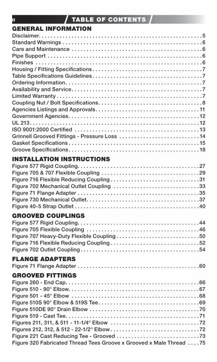
ii TABLE OF CONTENTS
GENERAL INFORMATIONDisclaimer. . . . . . . . . . . . . . . . . . . . . . . . . . . . . . . . . . . . . . . . . . . . . . . . . . . . . . . 5Standard Warnings . . . . . . . . . . . . . . . . . . . . . . . . . . . . . . . . . . . . . . . . . . . . . . . 6Care and Maintenance . . . . . . . . . . . . . . . . . . . . . . . . . . . . . . . . . . . . . . . . . . . . 6Pipe Support . . . . . . . . . . . . . . . . . . . . . . . . . . . . . . . . . . . . . . . . . . . . . . . . . . . . 6Finishes . . . . . . . . . . . . . . . . . . . . . . . . . . . . . . . . . . . . . . . . . . . . . . . . . . . . . . . . 6Housing / Fitting Specifications . . . . . . . . . . . . . . . . . . . . . . . . . . . . . . . . . . . . . 7Table Specifications Guidelines . . . . . . . . . . . . . . . . . . . . . . . . . . . . . . . . . . . . . 7Ordering Information . . . . . . . . . . . . . . . . . . . . . . . . . . . . . . . . . . . . . . . . . . . . . . 7Availability and Service . . . . . . . . . . . . . . . . . . . . . . . . . . . . . . . . . . . . . . . . . . . . 7Limited Warranty . . . . . . . . . . . . . . . . . . . . . . . . . . . . . . . . . . . . . . . . . . . . . . . . . 7Coupling Nut / Bolt Specifications . . . . . . . . . . . . . . . . . . . . . . . . . . . . . . . . . . . 8Agencies Listings and Approvals . . . . . . . . . . . . . . . . . . . . . . . . . . . . . . . . . . . 11Government Agencies . . . . . . . . . . . . . . . . . . . . . . . . . . . . . . . . . . . . . . . . . . . . 12UL 213 . . . . . . . . . . . . . . . . . . . . . . . . . . . . . . . . . . . . . . . . . . . . . . . . . . . . . . . . . 12ISO 9001:2000 Certified . . . . . . . . . . . . . . . . . . . . . . . . . . . . . . . . . . . . . . . . . . 13Grinnell Grooved Fittings - Pressure Loss . . . . . . . . . . . . . . . . . . . . . . . . . . . 14Gasket Specifications . . . . . . . . . . . . . . . . . . . . . . . . . . . . . . . . . . . . . . . . . . . . 15Groove Specifications . . . . . . . . . . . . . . . . . . . . . . . . . . . . . . . . . . . . . . . . . . . . 18
INSTALLATION INSTRUCTIONSFigure 577 Rigid Coupling . . . . . . . . . . . . . . . . . . . . . . . . . . . . . . . . . . . . . . . . . 27Figure 705 & 707 Flexible Coupling . . . . . . . . . . . . . . . . . . . . . . . . . . . . . . . . .29Figure 716 Flexible Reducing Coupling . . . . . . . . . . . . . . . . . . . . . . . . . . . . . . 31Figure 702 Mechanical Outlet Coupling . . . . . . . . . . . . . . . . . . . . . . . . . . . . .33Figure 71 Flange Adapter . . . . . . . . . . . . . . . . . . . . . . . . . . . . . . . . . . . . . . . . .35Figure 730 Mechanical Outlet . . . . . . . . . . . . . . . . . . . . . . . . . . . . . . . . . . . . . . 37Figure 40-5 Strap Outlet . . . . . . . . . . . . . . . . . . . . . . . . . . . . . . . . . . . . . . . . . .40
GROOVED COUPLINGSFigure 577 Rigid Coupling . . . . . . . . . . . . . . . . . . . . . . . . . . . . . . . . . . . . . . . . .44Figure 705 Flexible Coupling . . . . . . . . . . . . . . . . . . . . . . . . . . . . . . . . . . . . . .46Figure 707 Heavy-Duty Flexible Coupling . . . . . . . . . . . . . . . . . . . . . . . . . . . .50Figure 716 Flexible Reducing Coupling . . . . . . . . . . . . . . . . . . . . . . . . . . . . . . 52Figure 702 Outlet Coupling . . . . . . . . . . . . . . . . . . . . . . . . . . . . . . . . . . . . . . . .54
FLANGE ADAPTERSFigure 71 Flange Adapter . . . . . . . . . . . . . . . . . . . . . . . . . . . . . . . . . . . . . . . . .60
GROOVED FITTINGSFigure 260 - End Cap . . . . . . . . . . . . . . . . . . . . . . . . . . . . . . . . . . . . . . . . . . . . .66Figure 510 - 90° Elbow . . . . . . . . . . . . . . . . . . . . . . . . . . . . . . . . . . . . . . . . . . . . 67Figure 501 - 45° Elbow . . . . . . . . . . . . . . . . . . . . . . . . . . . . . . . . . . . . . . . . . . .68Figure 510S 90° Elbow & 519S Tee . . . . . . . . . . . . . . . . . . . . . . . . . . . . . . . . . .69Figure 510DE 90° Drain Elbow . . . . . . . . . . . . . . . . . . . . . . . . . . . . . . . . . . . . . 70Figure 519 - Cast Tee . . . . . . . . . . . . . . . . . . . . . . . . . . . . . . . . . . . . . . . . . . . . . 71Figures 211, 311, & 511 - 11-1/4º Elbow . . . . . . . . . . . . . . . . . . . . . . . . . . . . . . 72Figures 212, 312, & 512 - 22-1/2º Elbow . . . . . . . . . . . . . . . . . . . . . . . . . . . . . . 72Figure 221 Cast Reducing Tee - Grooved . . . . . . . . . . . . . . . . . . . . . . . . . . . . 73Figure 320 Fabricated Thread Tees Groove x Grooved x Male Thread . . . . 75
iiiTABLE OF CONTENTSFigure 321 Fabricated Reducing Tee - Grooved . . . . . . . . . . . . . . . . . . . . . . . 76Figure 323 Fabricated Reducing Tee - Grooved x Grooved x Male Thread . . . . . . . . . . . . . . . . . . . . . . . . . . . . . . . . . 81Figure 327 Fabricated Cross (Segment Welded) . . . . . . . . . . . . . . . . . . . . . .85Figure 250 Cast Concentric Reducers . . . . . . . . . . . . . . . . . . . . . . . . . . . . . . .86Figure 350 & 550 Concentric Reducers . . . . . . . . . . . . . . . . . . . . . . . . . . . . . .89Figure 372 Concentric Reducers Groove X Male Thread (MPT) . . . . . . . . . .94Figure 391, 392 & 393 Adapter Nipples . . . . . . . . . . . . . . . . . . . . . . . . . . . . . . 97ADACAP . . . . . . . . . . . . . . . . . . . . . . . . . . . . . . . . . . . . . . . . . . . . . . . . . . . . . . .98Figure 507/50L Bullhead Tee. . . . . . . . . . . . . . . . . . . . . . . . . . . . . . . . . . . . . . .99Figure 328 Standpipe Tee . . . . . . . . . . . . . . . . . . . . . . . . . . . . . . . . . . . . . . . . .99
OUTLET FITTINGSFigure 522 Sprinkler Outlet . . . . . . . . . . . . . . . . . . . . . . . . . . . . . . . . . . . . . . . 102Figure 730 Threaded Mechanical Tees & Crosses . . . . . . . . . . . . . . . . . . . . 104Figure 730 Grooved Mechanical Tees & Crosses . . . . . . . . . . . . . . . . . . . . . 114Figure 40-5 Strap (Pipe Outlet) . . . . . . . . . . . . . . . . . . . . . . . . . . . . . . . . . . . . 122
VALVESModel BFV-N Grooved End Butterfly Valve . . . . . . . . . . . . . . . . . . . . . . . . . . 124Resilient-Seated Gate Valve Outside Screw and Yoke . . . . . . . . . . . . . . . . . 126Resilient-Seated Post Indicator Gate Valve . . . . . . . . . . . . . . . . . . . . . . . . . 129Model CV-1F Check Valve . . . . . . . . . . . . . . . . . . . . . . . . . . . . . . . . . . . . . . . . 130
APPROVED PRESSURE RATINGSPipe Schedule Key . . . . . . . . . . . . . . . . . . . . . . . . . . . . . . . . . . . . . . . . . . . . . . 133Figure 577 Rigid Coupling . . . . . . . . . . . . . . . . . . . . . . . . . . . . . . . . . . . . . . . . 135Figure 705 Flexible Coupling . . . . . . . . . . . . . . . . . . . . . . . . . . . . . . . . . . . . . 138Figure 707 Heavy-Duty Flexible Coupling . . . . . . . . . . . . . . . . . . . . . . . . . . . 141Figure 716 Flexible Reducing Coupling . . . . . . . . . . . . . . . . . . . . . . . . . . . . . 144Figure 71 Flange Adapter . . . . . . . . . . . . . . . . . . . . . . . . . . . . . . . . . . . . . . . . 147Figure 702 Male Threaded Outlet Coupling . . . . . . . . . . . . . . . . . . . . . . . . . . 149Figure 702 Female Threaded Outlet Coupling . . . . . . . . . . . . . . . . . . . . . . . 150Figure 702 Grooved Outlet Coupling . . . . . . . . . . . . . . . . . . . . . . . . . . . . . . . 151Figure 730 Threaded Outlet . . . . . . . . . . . . . . . . . . . . . . . . . . . . . . . . . . . . . . 152Figure 730 Grooved Outlet . . . . . . . . . . . . . . . . . . . . . . . . . . . . . . . . . . . . . . . 162Figure 40-5 Strap Outlet . . . . . . . . . . . . . . . . . . . . . . . . . . . . . . . . . . . . . . . . . 169ADACAP . . . . . . . . . . . . . . . . . . . . . . . . . . . . . . . . . . . . . . . . . . . . . . . . . . . . . . 170Figure 260 End Cap . . . . . . . . . . . . . . . . . . . . . . . . . . . . . . . . . . . . . . . . . . . . . 171Figure 550 Reducer . . . . . . . . . . . . . . . . . . . . . . . . . . . . . . . . . . . . . . . . . . . . . 172Figure 501 45° Elbow . . . . . . . . . . . . . . . . . . . . . . . . . . . . . . . . . . . . . . . . . . . . 174Figure 510 90° Elbow . . . . . . . . . . . . . . . . . . . . . . . . . . . . . . . . . . . . . . . . . . . . 175Figure 519 Tee . . . . . . . . . . . . . . . . . . . . . . . . . . . . . . . . . . . . . . . . . . . . . . . . . 176Figure 510S 90° Elbow . . . . . . . . . . . . . . . . . . . . . . . . . . . . . . . . . . . . . . . . . . . 177Figure 519S Tee . . . . . . . . . . . . . . . . . . . . . . . . . . . . . . . . . . . . . . . . . . . . . . . . 177Figure 510DE Drain Elbow . . . . . . . . . . . . . . . . . . . . . . . . . . . . . . . . . . . . . . . 177Figure 391 GRV x Male Thread Adapter Nipples . . . . . . . . . . . . . . . . . . . . . 178Figure 392 GRV x GRV Adapter Nipples . . . . . . . . . . . . . . . . . . . . . . . . . . . . 178Figure 393 GRV x Bevel Adapter Nipples . . . . . . . . . . . . . . . . . . . . . . . . . . . 178Figure 341 GRV x Flange Adapter 150 Lbs. . . . . . . . . . . . . . . . . . . . . . . . . . . 178
iv TABLE OF CONTENTS
Figure 327 Cross . . . . . . . . . . . . . . . . . . . . . . . . . . . . . . . . . . . . . . . . . . . . . . . 178Figure 312 22-1/2° Elbow . . . . . . . . . . . . . . . . . . . . . . . . . . . . . . . . . . . . . . . . . 179Figure 321 Reducing Tee. . . . . . . . . . . . . . . . . . . . . . . . . . . . . . . . . . . . . . . . . 179Figure 350 Fabricated GRV x GRV Reducer . . . . . . . . . . . . . . . . . . . . . . . . . 179
SYSTEM DESIGNRigid Couplings . . . . . . . . . . . . . . . . . . . . . . . . . . . . . . . . . . . . . . . . . . . . . . . . 180Flexible Couplings . . . . . . . . . . . . . . . . . . . . . . . . . . . . . . . . . . . . . . . . . . . . . . 180Rotational Movement . . . . . . . . . . . . . . . . . . . . . . . . . . . . . . . . . . . . . . . . . . . 181Linear Movement . . . . . . . . . . . . . . . . . . . . . . . . . . . . . . . . . . . . . . . . . . . . . . . 181Linear Movement (Flexible Couplings) . . . . . . . . . . . . . . . . . . . . . . . . . . . . . . 182Angular Movement . . . . . . . . . . . . . . . . . . . . . . . . . . . . . . . . . . . . . . . . . . . . . 183Angular Deflection . . . . . . . . . . . . . . . . . . . . . . . . . . . . . . . . . . . . . . . . . . . . . . 183Expansion / Contraction . . . . . . . . . . . . . . . . . . . . . . . . . . . . . . . . . . . . . . . . . 184Thermal Movement . . . . . . . . . . . . . . . . . . . . . . . . . . . . . . . . . . . . . . . . . . . . . 184Misalignment and Deflection . . . . . . . . . . . . . . . . . . . . . . . . . . . . . . . . . . . . . 188
ENGINEERING REFERENCEDecimal Equivalents of Fractions . . . . . . . . . . . . . . . . . . . . . . . . . . . . . . . . . . 190Standard Conversion Factors . . . . . . . . . . . . . . . . . . . . . . . . . . . . . . . . . . . . . 191Minutes Converted To Decimals Of A Degree . . . . . . . . . . . . . . . . . . . . . . . . 192Water Feet Head Conversion . . . . . . . . . . . . . . . . . . . . . . . . . . . . . . . . . . . . . 193Pipe Thickness And Weight Per Line Foot . . . . . . . . . . . . . . . . . . . . . . . . . . 194

5GENERAL INFORMATION
TYCO Fire Protection Products is ISO 9001 Certified with products man-ufactured in our state of the art ductile iron foundry and manufacturing facilities. We are committed to maintaining our role in the fire protection industry through aggressive research and development. The products that will improve our industry are being designed today. With this level of investment and commitment, TYCO Fire Protection Products i prepared top become the industry standard.
TYCO Fire Protection Products is the world leader in the manufacture and distribution of fire protection products. Years of development, engi-neering, pattern and tooling manufacturing, and the acquisition of the necessary resources has provided the finest products available on the market today. TYCO Fire Protection Products manufactured domesti-cally or world-wide are offered to scrutinizing quality standards as set forth by independent testing laboratories.
Our Global Technology Center located in Cranston, RI, directs product development form concept through design, testing and manufacturing, then forwards all aspects of application engineering and quality assur-ance. Owners, architects, consulting engineers, contractors, and tenants demand the most dependable quality mechanical products for the piping systems - the Global Technology Center enure their demands are met each and every time.
The products and specifications published herein are for general evalu-ation and reference purposes only and are subject to change by TYCO Fire Protection Products without notice. For the most up-to-date infor-mation, visit www.tyco-fire.com. Information provided in this installa-tion handbook should not be relied on as s substitute for professional advice concerning specific applications. ALTHOUGH TYCO FIRE PRO-TECTION PRODUCTS HAS ENDEAVORED TO ENSURE ITS ACCU-RACY, ALL INFORMATION HEREIN IS PROVIDED ON AN “AS IS” BASIS, WITHOUT WARRANTY OF ANY KIND, EITHER EXPRESS OR IMPLIED. Without limiting the foregoing, TYCO Fire Protection Products does not warrant the accuracy, adequacy, or completeness of ay such informa-tion. All users of the information provided herein assume the risk of use or reliance on such information and TYCO Fire Protection Products shall not be liable for any damages for such use including, but not limited to, indirect, special, incidental, or consequential damages.*As used in this Table of Contents and Installation handbook, the designation “domestic” identifies the last point of manufacture or assembly for a product. However, this designation does not represent com-pliance with any government regulatory standards or contract specification and should not be relied upon for such purposes. Contact TYCO Trade Compliance to request separate certifications or other representations concerning the specific regulatory standards or contract specifications which apply to and specific regulatory standards or contact specifications.
Disclaimer
6 GENERAL INFORMATION
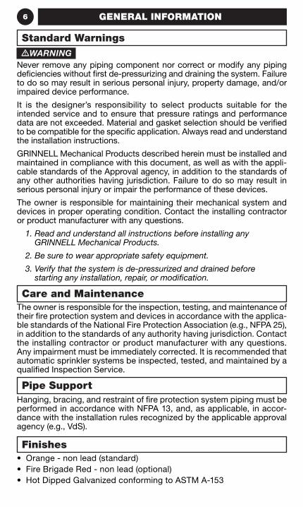
The owner is responsible for the inspection, testing, and maintenance of their fire protection system and devices in accordance with the applica-ble standards of the National Fire Protection Association (e.g., NFPA 25), in addition to the standards of any authority having jurisdiction. Contact the installing contractor or product manufacturer with any questions. Any impairment must be immediately corrected. It is recommended that automatic sprinkler systems be inspected, tested, and maintained by a qualified Inspection Service.
Hanging, bracing, and restraint of fire protection system piping must be performed in accordance with NFPA 13, and, as applicable, in accor-dance with the installation rules recognized by the applicable approval agency (e.g., VdS).
• Orange - non lead (standard)• Fire Brigade Red - non lead (optional)• Hot Dipped Galvanized conforming to ASTM A-153
•WARNINGNever remove any piping component nor correct or modify any piping deficiencies without first de-pressurizing and draining the system. Failure to do so may result in serious personal injury, property damage, and/or impaired device performance.
It is the designer’s responsibility to select products suitable for the intended service and to ensure that pressure ratings and performance data are not exceeded. Material and gasket selection should be verified to be compatible for the specific application. Always read and understand the installation instructions.
GRINNELL Mechanical Products described herein must be installed and maintained in compliance with this document, as well as with the appli-cable standards of the Approval agency, in addition to the standards of any other authorities having jurisdiction. Failure to do so may result in serious personal injury or impair the performance of these devices.
The owner is responsible for maintaining their mechanical system and devices in proper operating condition. Contact the installing contractor or product manufacturer with any questions.
1. Read and understand all instructions before installing any GRINNELL Mechanical Products.
2. Be sure to wear appropriate safety equipment.
3. Verify that the system is de-pressurized and drained before starting any installation, repair, or modification.
Care and Maintenance
Pipe Support
Finishes
Standard Warnings
7GENERAL INFORMATION
The applicable material specifications for ductile iron, galvanizing and rubber apply:
ASTM A-536 - (Cast Products)
Standard Specification for Ductile Iron Castings Grade 65-45-12, Tensile Strength, minimum psi: 65,000 Yield Strength, minimum psi: 45,000 Elongated in 2” or 50 mm, minimum 12%
ASTM A53 -
Schedule 40 Steel Pipe - Series 300 fittings
ASTM A-153 -
Standard Specification for Hot Dip Galvanizing
Throughout this handbook, nominal pipe sizes are referred to in “ANSI Inches” and “DN”. ANSI Inches is a nominal pipe size derived from the older IPS (Iron Pipe Size) in inches. Sizes offered in ANSI Inches directly correlate to nominal pipe sizes recognized in ANSI (American National Standard Institute) pipe standards.
DN refers to nominal pipe sizes in “diameter nominal” and is a dimen-sionless designator for nominal pipe sizes in metric. Certain DN sizes (for example, DN65, DN125, and DN150) are offered in multiple actual outside diameters. Consequently, when specifying by DN pipe size, the O.D. (outside diameter) must be specified as well.
When placing an order, indicate the full product name. When applicable, specify the figure number and size, type of gasket, material, and quantity.
Ordering Information
Availability and Service
GRINNELL Mechanical Products are available globally through a network of distribution centers. Visit www.grinnell.com or call 800-558-5236 for the nearest distributor.
Limited Warranty
For warranty terms and conditions, visit www.tyco-fire.com.
Housing / Fitting Specifications
Table Specifications Guidelines
8 GENERAL INFORMATION
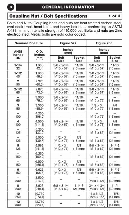
Bolts and Nuts: Coupling bolts and nuts are heat treated carbon steel, oval-neck track head bolts and heavy hex nuts, conforming to ASTM A-183 minimum tensile strength of 110,000 psi. Bolts and nuts are Zinc electroplated. Metric bolts are gold color coded.
Nominal Pipe Size Figure 577 Figure 705
ANSI Inches
DN
O.D. Inches (mm)
Inches (mm)
Inches (mm)
Bolt Size
Socket Size
Bolt Size
Socket Size
1-1/4 32
1.660 (42,4)
3/8 x 2-1/4 (M10 x 57)
11/16 (16 mm)
3/8 x 2-1/4 (M10 x 57)
11/16 (16 mm)
1-1/2 40
1.900 (48,3)
3/8 x 2-1/4 (M10 x 57)
11/16 (16 mm)
3/8 x 2-1/4 (M10 x 57)
11/16 (16 mm)
2 50
2.375 (60,3)
3/8 x 2-1/4 (M10 x 57)
11/16 (16 mm)
3/8 x 2-1/4 (M10 x 57)
11/16 (16 mm)
2-1/2 65
2.875 (73,0)
3/8 x 2-1/4 (M10 x 57)
11/16 (16 mm)
3/8 x 2-1/4 (M10 x 57)
11/16 (16 mm)
— 65
3.000 (76,2)
3/8 x 2-1/4 (M10 x 57)
11/16 (16 mm)
— (M12 x 76)
— (18 mm)
3 80
3.500 (88,9)
3/8 x 2-1/4 (M10 x 57)
11/16 (16 mm)
1/2 x 3 (M12 x 76)
7/8 (18 mm)
— 100
4.250 (108,0) — — —
(M12 x 76)—
(18 mm)
4 100
4.500 (114,3)
3/8 x 2-1/4 (M10 x 57)
11/16 (16 mm)
1/2 x 3 (M12 x 76)
7/8 (18 mm)
— 125
5.250 (133,0) — — —
(M16 x 83)—
(24 mm)
— 125
5.500 (139,7)
1/2 x 3 (M12 x 76)
7/8 (18 mm)
— (M16 x 83)
— (24 mm)
5 125
5.563 (141,3)
1/2 x 3 (M12 x 76)
7/8 (18 mm)
5/8 x 3-1/4 (M16 x 83)
1-1/16 (24 mm)
— 150
6.250 (159,0) — — —
(M16 x 83)—
(24 mm)
— 150
6.500 (165,1)
1/2 x 3 (M12 x 76)
7/8 (18 mm)
— (M16 x 83)
— (24 mm)
6 150
6.625 (168,3)
1/2 x 3 (M12 x 76)
7/8 (18 mm)
5/8 x 3-1/4 (M16 x 83)
1-1/16 (24 mm)
— 200
8.500 (216,3) — — —
(M20 x 121)—
(30 mm)
8 200
8.625 (219,1)
5/8 x 3-1/4 (M16 x 83)
1-1/16 (24 mm)
3/4 x 4-3/4 (M20 x 121)
1-1/4 (30 mm)
10 250
10.750 (273,1) — — 1 x 6-1/2
(M24 x 165)1-5/8
(41 mm)
12 300
12.750 (323,4) — — 1 x 6-1/2
(M24 x 165)1-5/8
(41 mm)
Coupling Nut / Bolt Specifications 1 of 3
9GENERAL INFORMATION
Nominal Pipe Size Figure 707 Figure 71*
ANSI Inches
DN
O.D.Inches(mm)
Inches(mm)
Inches(mm)
Bolt Size
Socket Size
Bolt Size
Socket Size
1-1/4 32
1.660(42,4)
1/2 x 3 (M12 x 76)
7/8 (18 mm) — —
1-1/2 40
1.900(48,3)
1/2 x 3 (M12 x 76)
7/8 (18 mm) — —
2 50
2.375(60,3)
1/2 x 3 (M12 x 76)
7/8 (18 mm)
5/8 x 3 (M16 x 76)
1-1/16 (24 mm)
2-1/2 65
2.875(73,0)
1/2 x 3 (M12 x 76)
7/8 (18 mm)
5/8 x 3 (M16 x 76)
1-1/16 (24 mm)
76,1mm 65
3.000(76,1)
— (M12 x 76)
— (18 mm) — —
3 80
3.500(88,9)
1/2 x 3 (M12 x 76)
7/8 (18 mm)
5/8 x 3 (M16 x 76)
1-1/16 (24 mm)
4 100
4.500 (114,3)
5/8 x 3-1/4 (M16 x 83)
1-1/16 (24 mm)
5/8 x 3 (M16 x 76)
1-1/16 (24 mm)
— 125
5.500 (139,7) — — 3/4 x 3-1/2
(M20 x 89)1-1/4
(30 mm)
5 125
5.563 (141,3)
3/4 x 4-3/4 (M20 x 121)
1-1/4 (30 mm)
3/4 x 3-1/2 (M20 x 89)
1-1/4 (30 mm)
165,1mm 150
6.500 (165,1)
— (M20 x 121)
— (30 mm) — —
6 150
6.625 (168,3)
3/4 x 4-3/4 (M20 x 121)
1-1/4 (30 mm)
3/4 x 3-1/2 (M20 x 89)
1-1/4 (30 mm)
8 200
8.625(219,1)
7/8 x 6-1/2 (M22 x 165)
1-7/16 (36 mm)
3/4 x 3-1/2 (M20 x 89)
1-1/4 (30 mm)
10 250
10.750(273,1)
1 x 6-1/2 (M24 x 165)
1-5/8 (41 mm)
7/8 x 4 (M22 x 102)
1-7/16 (36 mm)
12 300
12.750(323,4)
1 x 6-1/2 (M24 x 165)
1-5/8 (41 mm)
7/8 x 4 (M22 x 102)
1-7/16 (36 mm)
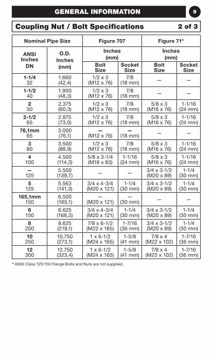
* ANSI Class 125/150 Flange Bolts and Nuts are not supplied.
Coupling Nut / Bolt Specifications 2 of 3
10 GENERAL INFORMATION
Nominal Pipe Size Figure 716 Figure 730
ANSI Inches
DN
O.D. Inches (mm)
Inches (mm)
Inches (mm)
Bolt Size
Socket Size
Bolt Size
Socket Size
2 50
2.375 (60,3)
3/8 x 2-1/4 (M10 x 57)
11/16 (16 mm)
3/8 x 2-1/4 (M10 x 57)
11/16 (16 mm)
2-1/2 65
2.875 (73,0)
3/8 x 2-1/4 (M10 x 57)
11/16 (16 mm)
3/8 x 2-1/4 (M10 x 57)
11/16 (16 mm)
— 65
3.000 (76,1)
— (M12 x 76)
— (18 mm)
— (M10 x 57)
— (16 mm)
3 80
3.500 (88,9)
1/2 x 3 (M12 x 76)
7/8 (18 mm)
1/2 x 3 (M12 x 76)
7/8 (18 mm)
— 100
4.500 (114,3)
— (M16 x 83)
— (24 mm)
— (M12 x 76)
— (18 mm)
4 100
4.500 (114,3)
5/8 x 3-1/4 (M16 x 83)
1-1/16 (24 mm)
1/2 x 3 (M12 x 76)
7/8 (18 mm)
— 125
5.500 (139,7)
— (M20 x 121)
— (30 mm)
— (M16 x 121)
— (24 mm)
5 125
5.563 (141,3)
3/4 x 4-3/4 (M20 x 121)
1-1/4 (30 mm)
5/8 x 4-3/4 (M16 x 121)
1-1/16 (24 mm)
— 150
6.500 (165,1)
— (M20 x 121)
— (30 mm)
— (M16 x 121)
— (24 mm)
6 150
6.625 (168,3)
3/4 x 4-3/4 (M20 x 121)
1-1/4 (30 mm)
5/8 x 4-3/4 (M16 x 121)
1-1/16 (24 mm)
— 200
8.515 (216,3) — — —
(M20 x 121)—
(30 mm)
8 200
8.625 (219,1)
7/8 x 6-1/2 (M22 x 165)
1-7/16 (36 mm)
3/4 x 4-3/4 (M20 x 121)
1-5/8 (41 mm)
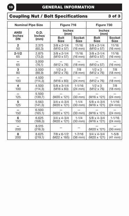
Coupling Nut / Bolt Specifications 3 of 3
11GENERAL INFORMATION
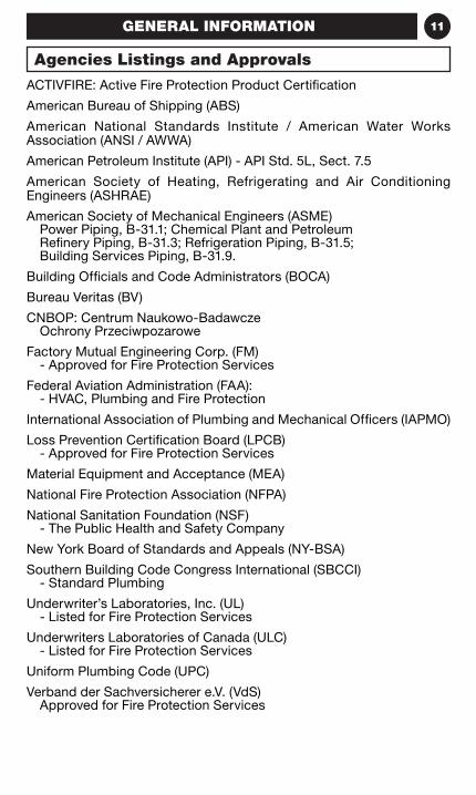
ACTIVFIRE: Active Fire Protection Product Certification
American Bureau of Shipping (ABS)
American National Standards Institute / American Water Works Association (ANSI / AWWA)
American Petroleum Institute (API) - API Std. 5L, Sect. 7.5
American Society of Heating, Refrigerating and Air Conditioning Engineers (ASHRAE)
American Society of Mechanical Engineers (ASME)Power Piping, B-31.1; Chemical Plant and Petroleum Refinery Piping, B-31.3; Refrigeration Piping, B-31.5; Building Services Piping, B-31.9.
Building Officials and Code Administrators (BOCA)
Bureau Veritas (BV)
CNBOP: Centrum Naukowo-BadawczeOchrony Przeciwpozarowe
Factory Mutual Engineering Corp. (FM)- Approved for Fire Protection Services
Federal Aviation Administration (FAA):- HVAC, Plumbing and Fire Protection
International Association of Plumbing and Mechanical Officers (IAPMO)
Loss Prevention Certification Board (LPCB)- Approved for Fire Protection Services
Material Equipment and Acceptance (MEA)
National Fire Protection Association (NFPA)
National Sanitation Foundation (NSF)- The Public Health and Safety Company
New York Board of Standards and Appeals (NY-BSA)
Southern Building Code Congress International (SBCCI)- Standard Plumbing
Underwriter’s Laboratories, Inc. (UL)- Listed for Fire Protection Services
Underwriters Laboratories of Canada (ULC)- Listed for Fire Protection Services
Uniform Plumbing Code (UPC)
Verband der Sachversicherer e.V. (VdS)Approved for Fire Protection Services
Agencies Listings and Approvals
12 GENERAL INFORMATION
Coast Guard - Approved each vessel individually
Corps of Engineers (COE) - GEGS 15000
Federal Aviation Administration (FAA) -
HVAC, Plumbing and Fire Protection
Federal Housing Administration (FHA)
General Services Administration (GSA) - 15000 Series
Military Specifications (MIL) - MILP - 10388 Fittings;
MIL - C - 10387 Couplings; MIL - P - 11087A (CE) Steel Pipe, Grooved MIL - I - 45208 Inspection Procedure
National Aeronautics and Space Administration (NASA)
Naval Facilities Engineering Command (NAVFAC)-
NFGS 15000 Series
National Institute of Health (NIH) - Dept. of Health - 15000 Series
Veterans Affairs (VA) - 15000 Series
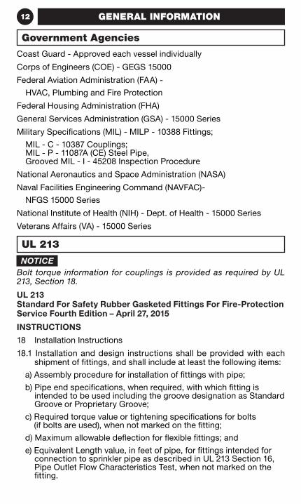
NOTICEBolt torque information for couplings is provided as required by UL 213, Section 18.
UL 213 Standard For Safety Rubber Gasketed Fittings For Fire-Protection Service Fourth Edition – April 27, 2015
INSTRUCTIONS
18 Installation Instructions
18.1 Installation and design instructions shall be provided with each shipment of fittings, and shall include at least the following items:
a) Assembly procedure for installation of fittings with pipe;
b) Pipe end specifications, when required, with which fitting is intended to be used including the groove designation as Standard Groove or Proprietary Groove;
c) Required torque value or tightening specifications for bolts (if bolts are used), when not marked on the fitting;
d) Maximum allowable deflection for flexible fittings; and
e) Equivalent Length value, in feet of pipe, for fittings intended for connection to sprinkler pipe as described in UL 213 Section 16, Pipe Outlet Flow Characteristics Test, when not marked on the fitting.
Government Agencies
UL 213
13GENERAL INFORMATION
Tyco Fire Protection Products are manufactured according to ISO 9001:2008 quality assurance standards.
ISO 9001:2000 Certified
14 GENERAL INFORMATION
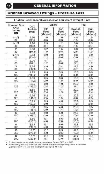
Friction Resistancea (Expressed as Equivalent Straight Pipe)
Nominal Size ANSI
Inches DN
O.D. Inches (mm)
Elbow Tee
90° Feet
(Meters)
45° Feet
(Meters)
Branch Feet
(Meters)
Run Feet
(Meters)1-1/4
321.60 (42,4)
1.9 (0,6)
1.0 (0,3)
4.8 (1,5)
1.9 (0,6)
1-1/2 40
1.90 (48,3)
2.3 (0,7)
1.2 (0,4)
5.8 (1,8)
2.3 (0,7)
2 50
2.38 (60,3)
3.2 (1,0)
1.6 (0,5)
8.0 (2,5)
3.2 (1,0)
2-1/2 65
2.88 (73,0)
3.9 (1,2)
2.0 (0,6)
9.8 (3,0)
3.9 (1,2)
— 65
3.00 (76,1)
4.1 (1,2)
2.1 (0,6)
10.3 (3,1)
4.1 (1,2)
3 80
3.50 (88,9)
4.9 (1,5)
2.4 (0,7)
12.2 (3,7)
4.9 (1,5)
— 100
4.25 (108,0)
6.5 (2,0)
3.3 (1,0)
16.3 (5,0)
6.5 (2,0)
4 100
4.50 (114,3)
6.5 (2,0)
3.3 (1,0)
16.3 (5,0)
6.5 (2,0)
— 125
5.25 (133,0)
8.0 (2,4)
4.0 (1,2)
20.0 (6,1)
8.0 (2,4)
— 125
5.50 (139,7)
8.0 (2,4)
4.1 (1,3)
20.0 (6,1)
8.0 (2,4)
5 125
5.56 (141,3)
8.2 (2,5)
4.1 (1,3)
20.5 (6,3)
8.2 (2,5)
— 150
6.25 (159,0)
9.5 (2,9)
4.8 (1,4)
23.8 (7,2)
9.5 (2,9)
— 150
6.50 (165,1)
9.5 (2,9)
4.8 (1,4)
23.8 (7,2)
9.5 (2,9)
6 150
6.63 (168,3)
9.9 (3,0)
5.0 (1,5)
24.8 (7,6)
9.9 (3,0)
— 200
8.50 (216,3)
13.1 (4,0)
6.6 (2,0)
32.8 (10,0)
13.1 (4,0)
8 200
8.63 (219,1)
13.1 (4,0)
6.6 (2,0)
32.8 (10,0)
13.1 (4,0)
10 250
10.75 (273,0)
16.5 (5,0)
8.3 (2,5)
41.3 (12,6)
16.5 (5,0)
12 300
12.75 (323,9)
19.9 (6,1)
9.9 (3,0)
49.7 (15,1)
19.9 (6,1)
a. Friction resistance for all elbows and tees except Figures 510S and 519S.• For reducing tees and branches, use the value that is corresponding to the branch size.
Example: for 8” x 8” x 2” tee, the branch value 2” is 8.0 feet.
Grinnell Grooved Fittings - Pressure Loss
15GENERAL INFORMATION
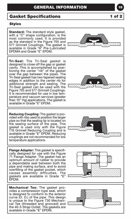
Standard: The standard style gasket, with a “C” shape configuration, is the most commonly used. It is provided as the standard in the Figure 705 and 577 Grinnell Couplings. The gasket is available in Grade “A” Pre-Lubricated EPDMA and Grade “E” EPDM.
Tri-Seal : The Tri-Seal gasket is designed to close off the gap or gasket cavity. This is accomplished by posi-tioning the center “rib” of the gasket over the gap between the pipes. The Tri-Seal gasket has two tapered sealing edges in addition to the center rib for additional strength and sealing. The Tri-Seal gasket can be used with the Figure 705 and 577 Grinnell Couplings. It is recommended for use in low tem-perature and vacuum services (greater than 10” Hg) applications. The gasket is available in Grade “E” EPDM.
Reducing Coupling: The gasket is pro-vided with ribs used to position the larger pipe so that the sealing lip is located on the sealing surface of the pipe. This gasket is used only with the Figure 716 Grinnell Reducing Coupling and is available in Grade “E” EPDM. Reducing couplings are not recommended for low temperature applications.
Flange Adapter: This gasket is specifi-cally designed for use with the Figure 71 Flange Adapter. The gasket has an optimum amount of rubber to provide a dependable seal between both the pipe and mating surface, and to avoid overfilling of the gasket pocket, which causes assembly difficulties. The gaskets are available in Grade “E” EPDM.
Mechanical Tee: The gasket pro-vides a compression type seal, which is designed to conform to the exterior curve (O. D.) of the pipe. This design is unique to the Figure 730 Mechani-cal Tee (threaded and grooved) and the 40-5 Strap Outlet. The gaskets are available in Grade “E” EPDM.
Styles
Gasket Specifications 1 of 2
16 GENERAL INFORMATION
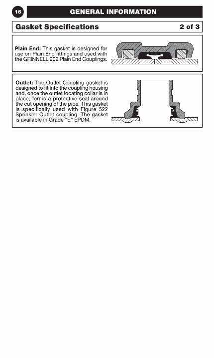
Plain End: This gasket is designed for use on Plain End fittings and used with the GRINNELL 909 Plain End Couplings.
Outlet: The Outlet Coupling gasket is designed to fit into the coupling housing and, once the outlet locating collar is in place, forms a protective seal around the cut opening of the pipe. This gasket is specifically used with Figure 522 Sprinkler Outlet coupling. The gasket is available in Grade “E” EPDM.
Gasket Specifications 2 of 3
17GENERAL INFORMATION
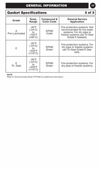
Grade Temp. Range
Compound & Color Code
General Service Application
A Pre-Lubricated
-30°F (-34°C)
to+150°F (+66°C)
EPDMViolet
Fire protection systems. Not recommended for hot water
systems. For dry pipe or freezer systems use Tri-Seal
Grade E Gaskets.
E
-30°F (-34°C)
to+230°F (+110°C)
EPDMGreen
Fire protection systems. For dry pipe or freezer systems use Tri-Seal Grade E Gas-
kets.
E Tri- Seal
-30°F (-34°C)
to+230°F (+110°C)
EPDMGreen
Fire protection systems. For dry pipe or freezer systems.
NOTERefer to Technical Data Sheet TFP1895 for additional information
Gasket Specifications 3 of 3
18
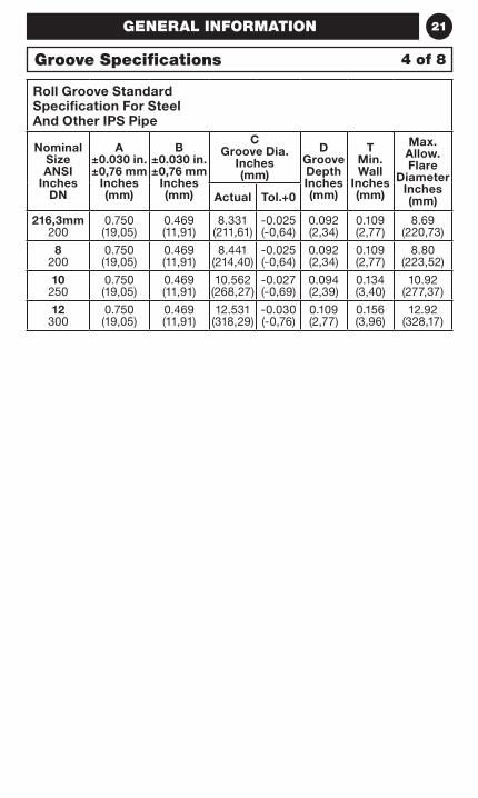
Roll Groove
GENERAL INFORMATION
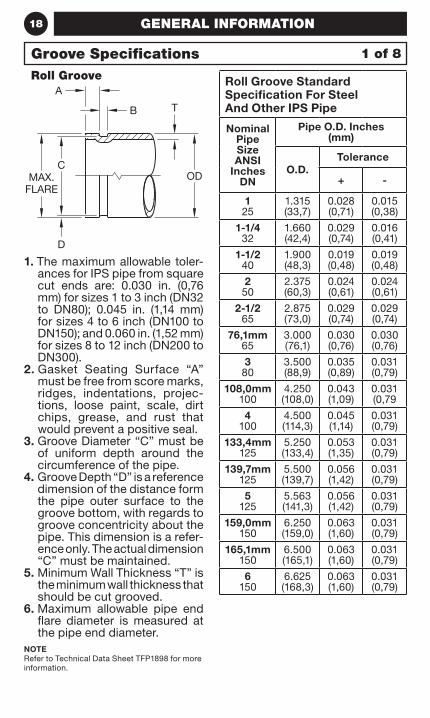
1. The maximum allowable toler-ances for IPS pipe from square cut ends are: 0.030 in. (0,76 mm) for sizes 1 to 3 inch (DN32 to DN80); 0.045 in. (1,14 mm) for sizes 4 to 6 inch (DN100 to DN150); and 0.060 in. (1,52 mm) for sizes 8 to 12 inch (DN200 to DN300).
2 . Gasket Seating Surface “A” must be free from score marks, ridges, indentations, projec-tions, loose paint, scale, dirt chips, grease, and rust that would prevent a positive seal.
3. Groove Diameter “C” must be of uniform depth around the circumference of the pipe.
4. Groove Depth “D” is a reference dimension of the distance form the pipe outer surface to the groove bottom, with regards to groove concentricity about the pipe. This dimension is a refer-ence only. The actual dimension “C” must be maintained.
5. Minimum Wall Thickness “T” is the minimum wall thickness that should be cut grooved.
6. Maximum allowable pipe end flare diameter is measured at the pipe end diameter.
NOTERefer to Technical Data Sheet TFP1898 for more information.
Roll Groove Standard Specification For Steel And Other IPS Pipe
Nominal Pipe Size ANSI
Inches DN
Pipe O.D. Inches (mm)
O.D.Tolerance
+ -
1 25
1.315(33,7)
0.028 (0,71)
0.015 (0,38)
1-1/4 32
1.660(42,4)
0.029 (0,74)
0.016 (0,41)
1-1/2 40
1.900(48,3)
0.019 (0,48)
0.019 (0,48)
2 50
2.375(60,3)
0.024 (0,61)
0.024 (0,61)
2-1/2 65
2.875(73,0)
0.029 (0,74)
0.029 (0,74)
76,1mm 65
3.000(76,1)
0.030 (0,76)
0.030 (0,76)
3 80
3.500(88,9)
0.035 (0,89)
0.031 (0,79)
108,0mm 100
4.250 (108,0)
0.043 (1,09)
0.031 (0,79
4 100
4.500(114,3)
0.045 (1,14)
0.031 (0,79)
133,4mm 125
5.250 (133,4)
0.053 (1,35)
0.031 (0,79)
139,7mm 125
5.500 (139,7)
0.056 (1,42)
0.031 (0,79)
5 125
5.563(141,3)
0.056 (1,42)
0.031 (0,79)
159,0mm 150
6.250 (159,0)
0.063 (1,60)
0.031 (0,79)
165,1mm 150
6.500(165,1)
0.063 (1,60)
0.031 (0,79)
6 150
6.625(168,3)
0.063 (1,60)
0.031 (0,79)
Groove Specifications 1 of 8
A
B T
D
CODMAX.
FLARE
19GENERAL INFORMATION
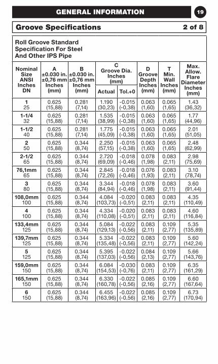
Roll Groove Standard Specification For Steel And Other IPS Pipe
Nominal Size ANSI
Inches DN
A ±0.030 in. ±0,76 mm
Inches (mm)
B ±0.030 in. ±0,76 mm
Inches (mm)
C Groove Dia.
Inches (mm)
D Groove Depth Inches (mm)
T Min. Wall
Inches (mm)
Max. Allow. Flare
Diameter Inches (mm)Actual Tol.+0
1 25
0.625 (15,88)
0.281 (7,14)
1.190 (30,23)
-0.015 (-0,38)
0.063 (1,60)
0.065 (1,65)
1.43 (36,32)
1-1/4 32
0.625 (15,88)
0.281 (7,14)
1.535 (38,99)
-0.015 (-0,38)
0.063 (1,60)
0.065 (1,65)
1.77 (44,96)
1-1/2 40
0.625 (15,88)
0.281 (7,14)
1.775 (45,09)
-0.015 (-0,38)
0.063 (1,60)
0.065 (1,65)
2.01 (51,05)
2 50
0.625 (15,88)
0.344 (8,74)
2.250 (57,15)
-0.015 (-0,38)
0.063 (1,60)
0.065 (1,65)
2.48 (62,99)
2-1/2 65
0.625 (15,88)
0.344 (8,74)
2.720 (69,09)
-0.018 (-0,46)
0.078 (1,98)
0.083 (2,11)
2.98 (75,69)
76,1mm 65
0.625 (15,88)
0.344 (8,74)
2.845 (72,26)
-0.018 (-0,46)
0.076 (1,93)
0.083 (2,11)
3.10 (78,74)
3 80
0.625 (15,88)
0.344 (8,74)
3.344 (84,94)
-0.018 (-0,46)
0.078 (1,98)
0.083 (2,11)
3.60 (91,44)
108,0mm 100
0.625 (15,88)
0.344 (8,74)
4.084 (103,73)
-0.020 (-0,51)
0.083 (2,11)
0.083 (2,11)
4.35 (110,49)
4 100
0.625 (15,88)
0.344 (8,74)
4.334 (110,08)
-0.020 (-0,51)
0.083 (2,11)
0.083 (2,11)
4.60 (116,84)
133,4mm 125
0.625 (15,88)
0.344 (8,74)
5.084 (129,13)
-0.022 (-0,56)
0.083 (2,11)
0.109 (2,77)
5.35 (135,89)
139,7mm 125
0.625 (15,88)
0.344 (8,74)
5.334 (135,48)
-0.022 (-0,56)
0.083 (2,11)
0.109 (2,77)
5.60 (142,24)
5 125
0.625 (15,88)
0.344 (8,74)
5.395 (137,03)
-0.022 (-0,56)
0.084 (2,13)
0.109 (2,77)
5.66 (143,76)
159,0mm 150
0.625 (15,88)
0.344 (8,74)
6.084 (154,53)
-0.030 (-0,76)
0.083 (2,11)
0.109 (2,77)
6.35 (161,29)
165,1mm 150
0.625 (15,88)
0.344 (8,74)
6.330 (160,78)
-0.022 (-0,56)
0.085 (2,16)
0.109 (2,77)
6.60 (167,64)
6 150
0.625 (15,88)
0.344 (8,74)
6.455 (163,96)
-0.022 (-0,56)
0.085 (2,16)
0.109 (2,77)
6.73 (170,94)
Groove Specifications 2 of 8

20 GENERAL INFORMATION
1. The maximum allowable toler-ances for IPS pipe from square cut ends are: 0.030 in. (0,76 mm) for sizes 1 to 3 inch (DN32 to DN80); 0.045 in. (1,14 mm) for sizes 4 to 6 inch (DN100 to DN150); and 0.060 in. (1,52 mm) for sizes 8 to 12 inch (DN200 to DN300).
2 . Gasket Seating Surface “A” must be free from score marks, ridges, indentations, projec-tions, loose paint, scale, dirt chips, grease, and rust that would prevent a positive seal.
3. Groove Diameter “C” must be of uniform depth around the circumference of the pipe.
4. Groove Depth “D” is a reference dimension of the distance form the pipe outer surface to the groove bottom, with regards to groove concentricity about the pipe. This dimension is a refer-ence only. The actual dimension “C” must be maintained.
5. Minimum Wall Thickness “T” is the minimum wall thickness that should be cut grooved.
6. Maximum allowable pipe end flare diameter is measured at the pipe end diameter.
NOTERefer to Technical Data Sheet TFP1898 for more information.
Roll Groove Roll Groove Standard Specification For Steel And Other IPS Pipe
Nominal Pipe Size ANSI
Inches DN
Pipe O.D. Inches (mm)
O.D.Tolerance
+ -
216,3mm 200
8.516 (216,3)
0.063 (1,60)
0.031(0,79)
8 200
8.625(219,1)
0.063 (1,60)
0.031 (0,79)
10 250
10.750 (273,0)
0.063 (1,60)
0.031 (0,79)
12 300
12.750 (323,9)
0.063 (1,60)
0.031 (0,79)
3 of 8Groove Specifications
A
B T
D
CODMAX.
FLARE
21GENERAL INFORMATION
Roll Groove Standard Specification For Steel And Other IPS Pipe
Nominal Size ANSI
Inches DN
A ±0.030 in. ±0,76 mm
Inches (mm)
B ±0.030 in. ±0,76 mm
Inches (mm)
C Groove Dia.
Inches (mm)
D Groove Depth Inches (mm)
T Min. Wall
Inches (mm)
Max. Allow. Flare
Diameter Inches (mm)Actual Tol.+0
216,3mm 200
0.750 (19,05)
0.469 (11,91)
8.331 (211,61)
-0.025 (-0,64)
0.092 (2,34)
0.109 (2,77)
8.69 (220,73)
8 200
0.750 (19,05)
0.469 (11,91)
8.441 (214,40)
-0.025 (-0,64)
0.092 (2,34)
0.109 (2,77)
8.80 (223,52)
10 250
0.750 (19,05)
0.469 (11,91)
10.562 (268,27)
-0.027 (-0,69)
0.094 (2,39)
0.134 (3,40)
10.92 (277,37)
12 300
0.750 (19,05)
0.469 (11,91)
12.531 (318,29)
-0.030 (-0,76)
0.109 (2,77)
0.156 (3,96)
12.92 (328,17)
Groove Specifications 4 of 8
22
5 of 8
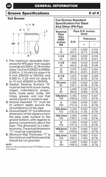
GENERAL INFORMATION
1. The maximum allowable toler-ances for IPS pipe from square cut ends is 0.030 in. (0,76 mm) for sizes 1 to 3 inch (DN32 to DN80); 0.045 in. (1,14 mm) for sizes 4 to 6 inch (DN100 to DN150); and 0.060 in. (1,52 mm) for sizes 8 to 12 inch (DN200 to DN300).
2 . Gasket Seating Surface “A” must be free from score marks, ridges, indentations, projec-tions, loose paint, scale, dirt chips, grease, and rust that would prevent a positive seal.
3. Groove Diameter “C” must be of uniform depth around the circumference of the pipe.
4. Groove Depth “D” is a reference dimension of the distance form the pipe outer surface to the groove bottom, with regards to groove concentricity about the pipe. This dimension is a refer-ence only. The actual dimension “C” must be maintained.
5. Minimum Wall Thickness “T” is the minimum wall thickness that should be cut grooved.
NOTERefer to Technical Data Sheet TFP1898 for more information.
Cut Groove Cut Groove Standard Specification For Steel And Other IPS Pipe
Nominal Pipe Size ANSI
Inches DN
Pipe O.D. Inches (mm)
O.D.Tolerance
+ -
1 25
1.315 (33,7)
0.028 (0,71)
0.015 (0,38)
1-1/4 32
1.660 (42,4)
0.029 (0,74)
0.016 (0,41)
1-1/2 40
1.900 (48,3)
0.019 (0,48)
0.019 (0,48)
2 50
2.375 (60,3)
0.024 (0,61)
0.024 (0,61)
2-1/2 65
2.875 (73,0)
0.029 (0,74)
0.029 (0,74)
76,1mm 65
3.000 (76,1)
0.030 (0,76)
0.030 (0,76)
3 80
3.500 (88,9)
0.035 (0,89)
0.031 (0,79)
108,0mm 100
4.250 (108,0)
0.042 (1,07)
0.031 (0,79)
4 100
4.500 (114,3)
0.045 (1,14)
0.031 (0,79)
133,4mm 125
5.250 (133,4)
0.052 (1,35)
0.031 (0,79)
139,7mm 125
5.500 (139,7)
0.056 (1,42)
0.031 (0,79)
5 125
5.563 (141,3)
0.056 (1,42)
0.031 (0,79)
159,0mm 150
6.250 (159,0)
0.063 (1,60)
0.031 (0,79)
165,1mm 150
6.500 (165,1)
0.063 (1,60)
0.031 (0,79)
6 150
6.625 (168,3)
0.063 (1,60)
0.031 (0,79)
Groove Specifications
A
B
T
COD
D
5 of 8
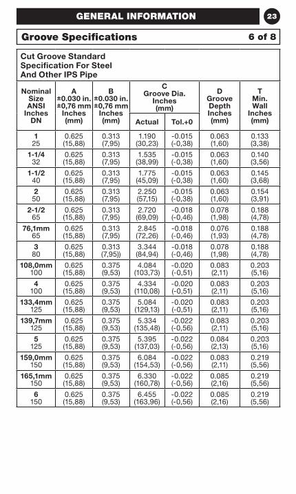
23GENERAL INFORMATION
Cut Groove Standard Specification For Steel And Other IPS Pipe
Nominal Size ANSI
Inches DN
A ±0.030 in. ±0,76 mm
Inches (mm)
B ±0.030 in. ±0,76 mm
Inches (mm)
C Groove Dia.
Inches (mm)
D Groove Depth Inches (mm)
T Min. Wall
Inches (mm)Actual Tol.+0
1 25
0.625 (15,88)
0.313 (7,95)
1.190 (30,23)
-0.015 (-0,38)
0.063 (1,60)
0.133 (3,38)
1-1/4 32
0.625 (15,88)
0.313 (7,95)
1.535 (38,99)
-0.015 (-0,38)
0.063 (1,60)
0.140 (3,56)
1-1/2 40
0.625 (15,88)
0.313 (7,95)
1.775 (45,09)
-0.015 (-0,38)
0.063 (1,60)
0.145 (3,68)
2 50
0.625 (15,88)
0.313 (7,95)
2.250 (57,15)
-0.015 (-0,38)
0.063 (1,60)
0.154 (3,91)
2-1/2 65
0.625 (15,88)
0.313 (7,95)
2.720 (69,09)
-0.018 (-0,46)
0.078 (1,98)
0.188 (4,78)
76,1mm 65
0.625 (15,88)
0.313 (7,95)
2.845 (72,26)
-0.018 (-0,46)
0.076 (1,93)
0.188 (4,78)
3 80
0.625 (15,88)
0.313 (7,95))
3.344 (84,94)
-0.018 (-0,46)
0.078 (1,98)
0.188 (4,78)
108,0mm 100
0.625 (15,88)
0.375 (9,53)
4.084 (103,73)
-0.020 (-0,51)
0.083 (2,11)
0.203 (5,16)
4 100
0.625 (15,88)
0.375 (9,53)
4.334 (110,08)
-0.020 (-0,51)
0.083 (2,11)
0.203 (5,16)
133,4mm 125
0.625 (15,88)
0.375 (9,53)
5.084 (129,13)
-0.020 (-0,51)
0.083 (2,11)
0.203 (5,16)
139,7mm 125
0.625 (15,88)
0.375 (9,53)
5.334 (135,48)
-0.022 (-0,56)
0.083 (2,11)
0.203 (5,16)
5 125
0.625 (15,88)
0.375 (9,53)
5.395 (137,03)
-0.022 (-0,56)
0.084 (2,13)
0.203 (5,16)
159,0mm 150
0.625 (15,88)
0.375 (9,53)
6.084 (154,53)
-0.022 (-0,56)
0.083 (2,11)
0.219 (5,56)
165,1mm 150
0.625 (15,88)
0.375 (9,53)
6.330 (160,78)
-0.022 (-0,56)
0.085 (2,16)
0.219 (5,56)
6 150
0.625 (15,88)
0.375 (9,53)
6.455 (163,96)
-0.022 (-0,56)
0.085 (2,16)
0.219 (5,56)
Groove Specifications 6 of 8
24
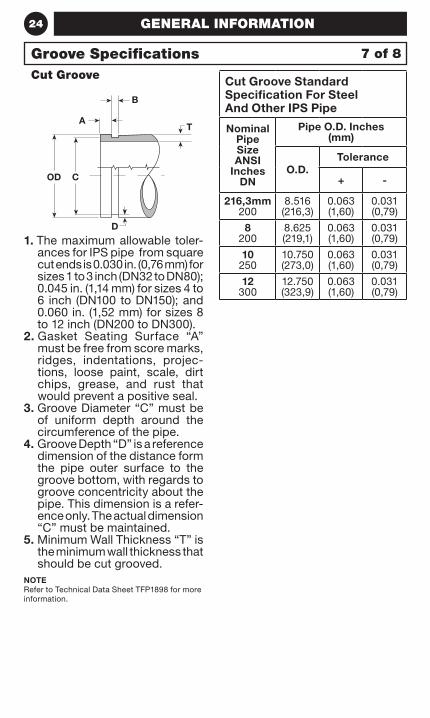
Cut Groove
GENERAL INFORMATION
1. The maximum allowable toler-ances for IPS pipe from square cut ends is 0.030 in. (0,76 mm) for sizes 1 to 3 inch (DN32 to DN80); 0.045 in. (1,14 mm) for sizes 4 to 6 inch (DN100 to DN150); and 0.060 in. (1,52 mm) for sizes 8 to 12 inch (DN200 to DN300).
2 . Gasket Seating Surface “A” must be free from score marks, ridges, indentations, projec-tions, loose paint, scale, dirt chips, grease, and rust that would prevent a positive seal.
3. Groove Diameter “C” must be of uniform depth around the circumference of the pipe.
4. Groove Depth “D” is a reference dimension of the distance form the pipe outer surface to the groove bottom, with regards to groove concentricity about the pipe. This dimension is a refer-ence only. The actual dimension “C” must be maintained.
5. Minimum Wall Thickness “T” is the minimum wall thickness that should be cut grooved.
NOTERefer to Technical Data Sheet TFP1898 for more information.
Cut Groove Standard Specification For Steel And Other IPS Pipe
Nominal Pipe Size ANSI
Inches DN
Pipe O.D. Inches (mm)
O.D.Tolerance
+ -
216,3mm 200
8.516 (216,3)
0.063 (1,60)
0.031 (0,79)
8 200
8.625 (219,1)
0.063 (1,60)
0.031 (0,79)
10 250
10.750 (273,0)
0.063 (1,60)
0.031 (0,79)
12 300
12.750 (323,9)
0.063 (1,60)
0.031 (0,79)
Groove Specifications 7 of 8
A
B
T
COD
D
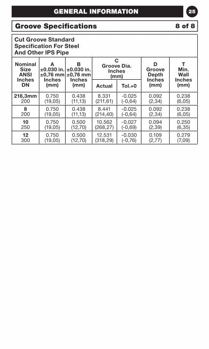
25GENERAL INFORMATION
Cut Groove Standard Specification For Steel And Other IPS Pipe
Nominal Size ANSI
Inches DN
A ±0.030 in. ±0,76 mm
Inches (mm)
B ±0.030 in. ±0,76 mm
Inches (mm)
C Groove Dia.
Inches (mm)
D Groove Depth Inches (mm)
T Min. Wall
Inches (mm)Actual Tol.+0
216,3mm 200
0.750 (19,05)
0.438 (11,13)
8.331 (211,61)
-0.025 (-0,64)
0.092 (2,34)
0.238 (6,05)
8 200
0.750 (19,05)
0.438 (11,13)
8.441 (214,40)
-0.025 (-0,64)
0.092 (2,34)
0.238 (6,05)
10 250
0.750 (19,05)
0.500 (12,70)
10.562 (268,27)
-0.027 (-0,69)
0.094 (2,39)
0.250 (6,35)
12 300
0.750 (19,05)
0.500 (12,70)
12.531 (318,29)
-0.030 (-0,76)
0.109 (2,77)
0.279 (7,09)
Groove Specifications 8 of 8

26 GENERAL INFORMATION
THIS PAGE INTENTIONALLY LEFT BLANK
27
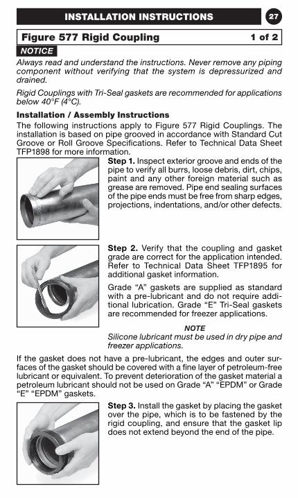
NOTICEAlways read and understand the instructions. Never remove any piping component without verifying that the system is depressurized and drained.
Rigid Couplings with Tri-Seal gaskets are recommended for applications below 40°F (4°C).
Installation / Assembly InstructionsThe following instructions apply to Figure 577 Rigid Couplings. The installation is based on pipe grooved in accordance with Standard Cut Groove or Roll Groove Specifications. Refer to Technical Data Sheet TFP1898 for more information.
Step 2. Verify that the coupling and gasket grade are correct for the application intended. Refer to Technical Data Sheet TFP1895 for additional gasket information.
Grade “A” gaskets are supplied as standard with a pre-lubricant and do not require addi-tional lubrication. Grade “E” Tri-Seal gaskets are recommended for freezer applications.
NOTESilicone lubricant must be used in dry pipe and freezer applications.
If the gasket does not have a pre-lubricant, the edges and outer sur-faces of the gasket should be covered with a fine layer of petroleum-free lubricant or equivalent. To prevent deterioration of the gasket material a petroleum lubricant should not be used on Grade “A” “EPDM” or Grade “E” “EPDM” gaskets.
Step 3. Install the gasket by placing the gasket over the pipe, which is to be fastened by the rigid coupling, and ensure that the gasket lip does not extend beyond the end of the pipe.
Step 1. Inspect exterior groove and ends of the pipe to verify all burrs, loose debris, dirt, chips, paint and any other foreign material such as grease are removed. Pipe end sealing surfaces of the pipe ends must be free from sharp edges, projections, indentations, and/or other defects.
Figure 577 Rigid Coupling
INSTALLATION INSTRUCTIONS
1 of 2
28
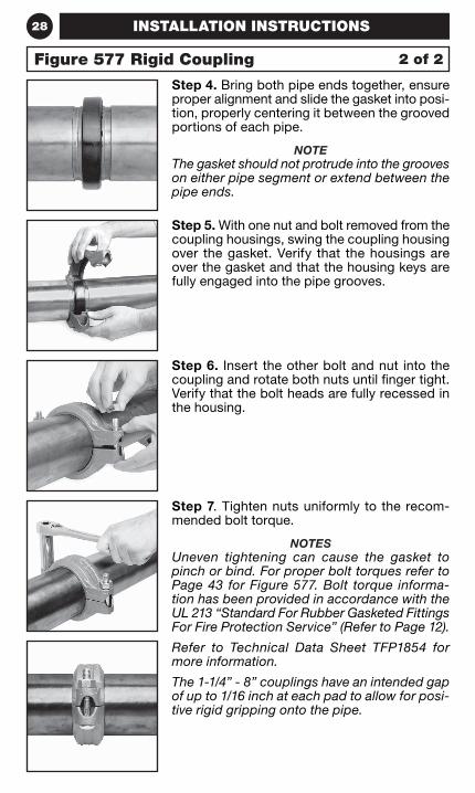
Step 4. Bring both pipe ends together, ensure proper alignment and slide the gasket into posi-tion, properly centering it between the grooved portions of each pipe.
NOTEThe gasket should not protrude into the grooves on either pipe segment or extend between the pipe ends.
Step 5. With one nut and bolt removed from the coupling housings, swing the coupling housing over the gasket. Verify that the housings are over the gasket and that the housing keys are fully engaged into the pipe grooves.
Step 6. Insert the other bolt and nut into the coupling and rotate both nuts until finger tight. Verify that the bolt heads are fully recessed in the housing.
Step 7. Tighten nuts uniformly to the recom-mended bolt torque.
NOTESUneven tightening can cause the gasket to pinch or bind. For proper bolt torques refer to Page 43 for Figure 577. Bolt torque informa-tion has been provided in accordance with the UL 213 “Standard For Rubber Gasketed Fittings For Fire Protection Service” (Refer to Page 12).
Refer to Technical Data Sheet TFP1854 for more information.
The 1-1/4” - 8” couplings have an intended gap of up to 1/16 inch at each pad to allow for posi-tive rigid gripping onto the pipe.
Figure 577 Rigid Coupling
INSTALLATION INSTRUCTIONS
2 of 2
29
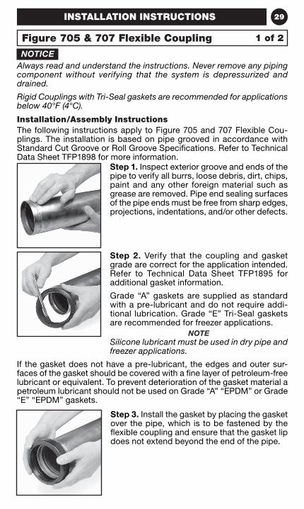
NOTICEAlways read and understand the instructions. Never remove any piping component without verifying that the system is depressurized and drained.
Rigid Couplings with Tri-Seal gaskets are recommended for applications below 40°F (4°C).
Installation/Assembly InstructionsThe following instructions apply to Figure 705 and 707 Flexible Cou-plings. The installation is based on pipe grooved in accordance with Standard Cut Groove or Roll Groove Specifications. Refer to Technical Data Sheet TFP1898 for more information.
Step 3. Install the gasket by placing the gasket over the pipe, which is to be fastened by the flexible coupling and ensure that the gasket lip does not extend beyond the end of the pipe.
Step 2. Verify that the coupling and gasket grade are correct for the application intended. Refer to Technical Data Sheet TFP1895 for additional gasket information.
Grade “A” gaskets are supplied as standard with a pre-lubricant and do not require addi-tional lubrication. Grade “E” Tri-Seal gaskets are recommended for freezer applications.
NOTESilicone lubricant must be used in dry pipe and freezer applications.
If the gasket does not have a pre-lubricant, the edges and outer sur-faces of the gasket should be covered with a fine layer of petroleum-free lubricant or equivalent. To prevent deterioration of the gasket material a petroleum lubricant should not be used on Grade “A” “EPDM” or Grade “E” “EPDM” gaskets.
Step 1. Inspect exterior groove and ends of the pipe to verify all burrs, loose debris, dirt, chips, paint and any other foreign material such as grease are removed. Pipe end sealing surfaces of the pipe ends must be free from sharp edges, projections, indentations, and/or other defects.
Figure 705 & 707 Flexible Coupling
INSTALLATION INSTRUCTIONS
1 of 2
30
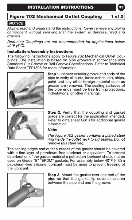
Step 7. Tighten nuts uniformly to the recom-mended bolt torque.
NOTEUneven tightening can cause the gasket to pinch or bind. For proper bolt torques refer to Pages 45 and 49. Bolt torque information has been provided in accordance with the UL 213 “Standard for Rubber Gasketed Fittings for Fire Protection Service” (Refer to Page 12).
Refer to Technical Data Sheets TFP1820 (Figure 705) or TFP1840 (Figure 707) for more information.
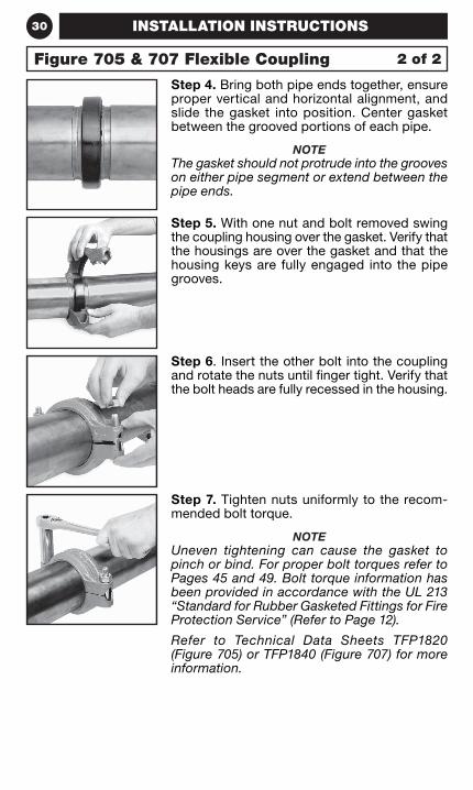
Step 4. Bring both pipe ends together, ensure proper vertical and horizontal alignment, and slide the gasket into position. Center gasket between the grooved portions of each pipe.
NOTEThe gasket should not protrude into the grooves on either pipe segment or extend between the pipe ends.
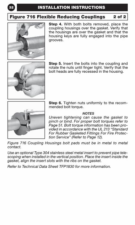
Step 6. Insert the other bolt into the coupling and rotate the nuts until finger tight. Verify that the bolt heads are fully recessed in the housing.
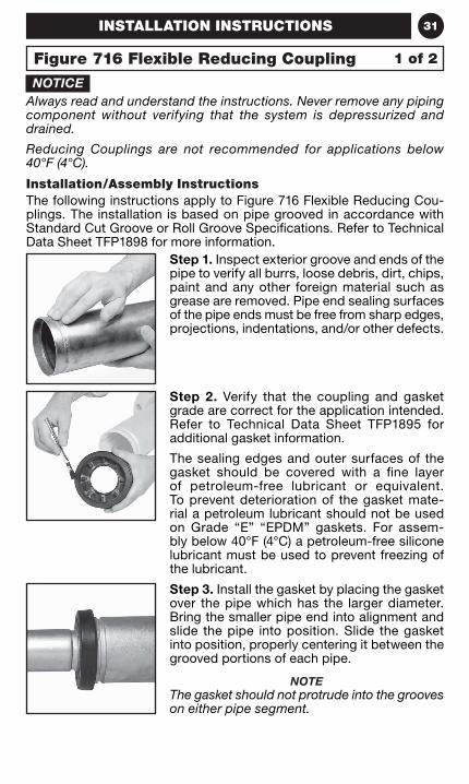
Step 5. With one nut and bolt removed swing the coupling housing over the gasket. Verify that the housings are over the gasket and that the housing keys are fully engaged into the pipe grooves.
Figure 705 & 707 Flexible Coupling
INSTALLATION INSTRUCTIONS
2 of 2
31
NOTICEAlways read and understand the instructions. Never remove any piping component without verifying that the system is depressurized and drained.
Reducing Couplings are not recommended for applications below 40°F (4°C).
Installation/Assembly InstructionsThe following instructions apply to Figure 716 Flexible Reducing Cou-plings. The installation is based on pipe grooved in accordance with Standard Cut Groove or Roll Groove Specifications. Refer to Technical Data Sheet TFP1898 for more information.
Step 3. Install the gasket by placing the gasket over the pipe which has the larger diameter. Bring the smaller pipe end into alignment and slide the pipe into position. Slide the gasket into position, properly centering it between the grooved portions of each pipe.
NOTEThe gasket should not protrude into the grooves on either pipe segment.
Step 2. Verify that the coupling and gasket grade are correct for the application intended. Refer to Technical Data Sheet TFP1895 for additional gasket information.
The sealing edges and outer surfaces of the gasket should be covered with a fine layer of petroleum-free lubricant or equivalent. To prevent deterioration of the gasket mate-rial a petroleum lubricant should not be used on Grade “E” “EPDM” gaskets. For assem-bly below 40°F (4°C) a petroleum-free silicone lubricant must be used to prevent freezing of the lubricant.
Step 1. Inspect exterior groove and ends of the pipe to verify all burrs, loose debris, dirt, chips, paint and any other foreign material such as grease are removed. Pipe end sealing surfaces of the pipe ends must be free from sharp edges, projections, indentations, and/or other defects.
Figure 716 Flexible Reducing Coupling
INSTALLATION INSTRUCTIONS
1 of 2
32
Step 4. With both bolts removed, place the coupling housings over the gasket. Verify that the housings are over the gasket and that the housing keys are fully engaged into the pipe grooves.
Step 6. Tighten nuts uniformly to the recom-mended bolt torque.
NOTESUneven tightening can cause the gasket to pinch or bind. For proper bolt torques refer to Page 51. Bolt torque information has been pro-vided in accordance with the UL 213 “Standard For Rubber Gasketed Fittings For Fire Protec-tion Service” (Refer to Page 12).
Figure 716 Coupling Housings bolt pads must be in metal to metal contact.
Use an optional Type 304 stainless steel metal insert to prevent pipe tele-scoping when installed in the vertical position. Place the insert inside the gasket, align the insert slots with the ribs on the gasket.
Refer to Technical Data Sheet TFP1830 for more information.
Step 5. Insert the bolts into the coupling and rotate the nuts until finger tight. Verify that the bolt heads are fully recessed in the housing.
Figure 716 Flexible Reducing Couplings
INSTALLATION INSTRUCTIONS
2 of 2
33
Step 1. Inspect exterior groove and ends of the pipe to verify all burrs, loose debris, dirt, chips, paint and any other foreign material such as grease are removed. The sealing surfaces of the pipe ends must be free from projections, indentations, or other markings.
NOTICEAlways read and understand the instructions. Never remove any piping component without verifying that the system is depressurized and drained.
Reducing Couplings are not recommended for applications below 40°F (4°C).
Installation/Assembly InstructionsThe following instructions apply to Figure 702 Mechanical Outlet Cou-plings. The installation is based on pipe grooved in accordance with Standard Cut Groove or Roll Groove Specifications. Refer to Technical Data Sheet TFP1898 for more information.
Step 2. Verify that the coupling and gasket grade are correct for the application intended. Refer to data sheet G610 for additional gasket information.
Note:
The Figure 702 gasket contains a plated steel ring inside the outlet neck to aid sealing. Do not remove this steel ring.
The sealing edges and outer surfaces of the gasket should be covered with a fine layer of petroleum-free lubricant or equivalent. To prevent deterioration of the gasket material a petroleum lubricant should not be used on Grade “E” “EPDM” gaskets. For assembly below 40°F (4°C) a petroleum-free silicone lubricant must be used to prevent freezing of the lubricant.
Step 3. Mount the gasket over one end of the pipe so that the gasket lip covers the area between the pipe end and the groove.
INSTALLATION INSTRUCTIONS
Figure 702 Mechanical Outlet Coupling 1 of 2
34
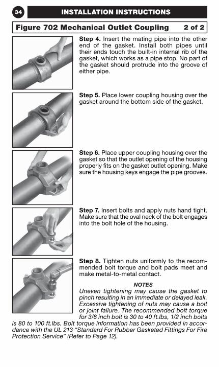
Step 4. Insert the mating pipe into the other end of the gasket. Install both pipes until their ends touch the built-in internal rib of the gasket, which works as a pipe stop. No part of the gasket should protrude into the groove of either pipe.
Step 5. Place lower coupling housing over the gasket around the bottom side of the gasket.
Step 6. Place upper coupling housing over the gasket so that the outlet opening of the housing properly fits on the gasket outlet opening. Make sure the housing keys engage the pipe grooves.
Step 7. Insert bolts and apply nuts hand tight. Make sure that the oval neck of the bolt engages into the bolt hole of the housing.
Step 8. Tighten nuts uniformly to the recom-mended bolt torque and bolt pads meet and make metal-to-metal contact.
NOTESUneven tightening may cause the gasket to pinch resulting in an immediate or delayed leak. Excessive tightening of nuts may cause a bolt or joint failure. The recommended bolt torque for 3/8 inch bolt is 30 to 40 ft.lbs, 1/2 inch bolts
is 80 to 100 ft.lbs. Bolt torque information has been provided in accor-dance with the UL 213 “Standard For Rubber Gasketed Fittings For Fire Protection Service” (Refer to Page 12).
INSTALLATION INSTRUCTIONS
Figure 702 Mechanical Outlet Coupling 2 of 2
35
NOTEAlways read and understand the instructions. Never remove any piping component without verifying that the system is depressurized and drained.
Installation/Assembly InstructionsThe following instructions apply to Figure 71 Flange Adapter. The instal-lation is based on pipe grooved in accordance with Standard Cut Groove or Roll Groove Specifications. Refer to Technical Data Sheet TFP1898 for more information.
Step 3. Close the flange with another bolt. To ease in the closure of the flange, two tabs are provided. Take an adjustable wrench and place it over the two tabs as shown. Move the wrench parallel to the pipe until the holes align. Once the holes align, insert a bolt. Verify that the housing keys are fully engaged into the groove.
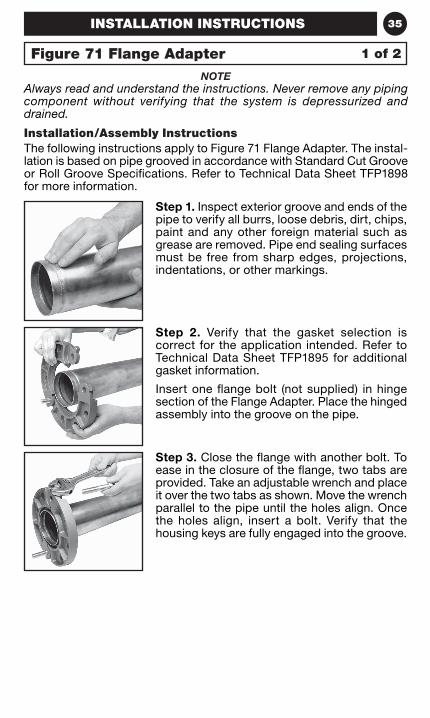
Step 1. Inspect exterior groove and ends of the pipe to verify all burrs, loose debris, dirt, chips, paint and any other foreign material such as grease are removed. Pipe end sealing surfaces must be free from sharp edges, projections, indentations, or other markings.
Step 2. Verify that the gasket selection is correct for the application intended. Refer to Technical Data Sheet TFP1895 for additional gasket information.
Insert one flange bolt (not supplied) in hinge section of the Flange Adapter. Place the hinged assembly into the groove on the pipe.
Figure 71 Flange Adapter
INSTALLATION INSTRUCTIONS
1 of 2
36
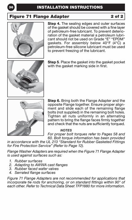
Step 5. Place the gasket into the gasket pocket with the gasket marking side in first.
Step 4. The sealing edges and outer surfaces of the gasket should be covered with a fine layer of petroleum-free lubricant. To prevent deterio-ration of the gasket material a petroleum lubri-cant should not be used on Grade “E” “EPDM” gaskets. For assembly below 40°F (4°C) a petroleum-free silicone lubricant must be used to prevent freezing of the lubricant.
Step 6. Bring both the Flange Adapter and the opposite Flange together. Ensure proper align-ment and slide each of the remaining flange bolts (not supplied) in the remaining bolt holes. Tighten all nuts uniformly in an alternating pattern to bring the flange faces firmly together and check that the nuts are sufficiently torqued.
NOTESFor proper bolt torques refer to Pages 58 and 60. Bolt torque information has been provided
in accordance with the UL 213 “Standard for Rubber Gasketed Fittings for Fire Protection Service” (Refer to Page 12).
Flange Washer Adapters are required when the Figure 71 Flange Adapter is used against surfaces such as:
1. Rubber surfaces2. Adapting to AWWA cast flanges3. Rubber faced wafer valves4. Serrated flange surfaces
Figure 71 Flange Adapters are not recommended for applications that incorporate tie rods for anchoring, or on standard fittings within 90° of each other. Refer to Technical Data Sheet TFP1880 for more information.
Figure 71 Flange Adapter
INSTALLATION INSTRUCTIONS
2 of 2
37
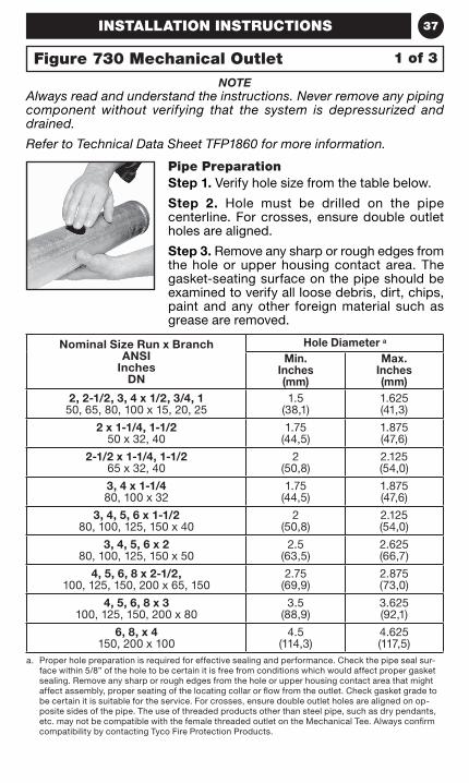
Pipe PreparationStep 1. Verify hole size from the table below.
Step 2. Hole must be drilled on the pipe centerline. For crosses, ensure double outlet holes are aligned.
Step 3. Remove any sharp or rough edges from the hole or upper housing contact area. The gasket-seating surface on the pipe should be examined to verify all loose debris, dirt, chips, paint and any other foreign material such as grease are removed.
NOTEAlways read and understand the instructions. Never remove any piping component without verifying that the system is depressurized and drained.
Refer to Technical Data Sheet TFP1860 for more information.
Nominal Size Run x Branch ANSI
Inches DN
Hole Diameter a
Min. Inches (mm)
Max. Inches (mm)
2, 2-1/2, 3, 4 x 1/2, 3/4, 1 50, 65, 80, 100 x 15, 20, 25
1.5 (38,1)
1.625 (41,3)
2 x 1-1/4, 1-1/2 50 x 32, 40
1.75 (44,5)
1.875 (47,6)
2-1/2 x 1-1/4, 1-1/2 65 x 32, 40
2 (50,8)
2.125 (54,0)
3, 4 x 1-1/4 80, 100 x 32
1.75 (44,5)
1.875 (47,6)
3, 4, 5, 6 x 1-1/2 80, 100, 125, 150 x 40
2 (50,8)
2.125 (54,0)
3, 4, 5, 6 x 2 80, 100, 125, 150 x 50
2.5 (63,5)
2.625 (66,7)
4, 5, 6, 8 x 2-1/2, 100, 125, 150, 200 x 65, 150
2.75 (69,9)
2.875 (73,0)
4, 5, 6, 8 x 3 100, 125, 150, 200 x 80
3.5 (88,9)
3.625 (92,1)
6, 8, x 4 150, 200 x 100
4.5 (114,3)
4.625 (117,5)
a. Proper hole preparation is required for effective sealing and performance. Check the pipe seal sur-face within 5/8” of the hole to be certain it is free from conditions which would affect proper gasket sealing. Remove any sharp or rough edges from the hole or upper housing contact area that might affect assembly, proper seating of the locating collar or flow from the outlet. Check gasket grade to be certain it is suitable for the service. For crosses, ensure double outlet holes are aligned on op-posite sides of the pipe. The use of threaded products other than steel pipe, such as dry pendants, etc. may not be compatible with the female threaded outlet on the Mechanical Tee. Always confirm compatibility by contacting Tyco Fire Protection Products.
Figure 730 Mechanical Outlet 1 of 3
INSTALLATION INSTRUCTIONS
38
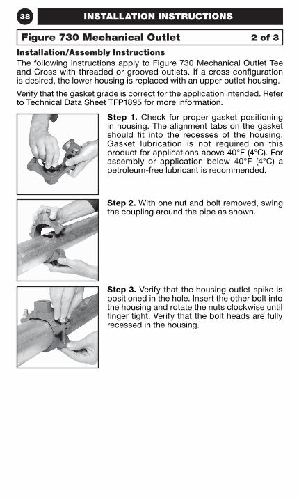
Installation/Assembly InstructionsThe following instructions apply to Figure 730 Mechanical Outlet Tee and Cross with threaded or grooved outlets. If a cross configuration is desired, the lower housing is replaced with an upper outlet housing.
Verify that the gasket grade is correct for the application intended. Refer to Technical Data Sheet TFP1895 for more information.
Step 1. Check for proper gasket positioning in housing. The alignment tabs on the gasket should fit into the recesses of the housing. Gasket lubrication is not required on this product for applications above 40°F (4°C). For assembly or application below 40°F (4°C) a petroleum-free lubricant is recommended.
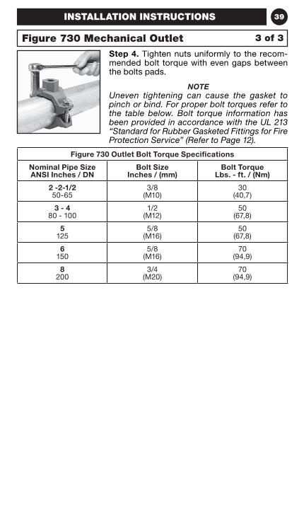
Step 2. With one nut and bolt removed, swing the coupling around the pipe as shown.
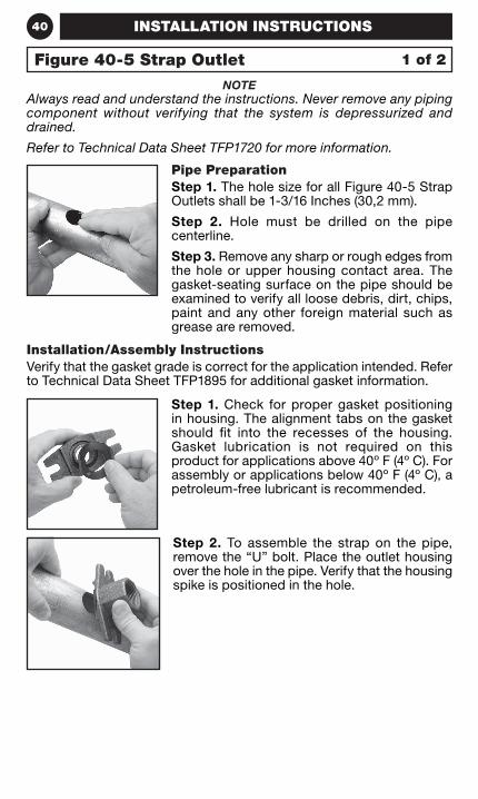
Step 3. Verify that the housing outlet spike is positioned in the hole. Insert the other bolt into the housing and rotate the nuts clockwise until finger tight. Verify that the bolt heads are fully recessed in the housing.
Figure 730 Mechanical Outlet
INSTALLATION INSTRUCTIONS
2 of 3
39
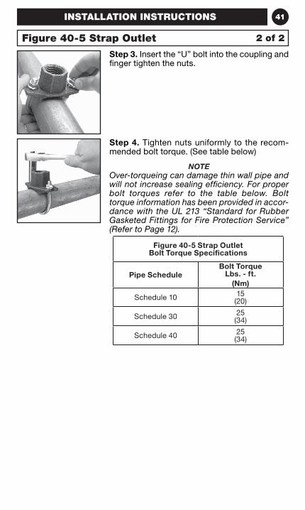
Step 4. Tighten nuts uniformly to the recom-mended bolt torque with even gaps between the bolts pads.
NOTEUneven tightening can cause the gasket to pinch or bind. For proper bolt torques refer to the table below. Bolt torque information has been provided in accordance with the UL 213 “Standard for Rubber Gasketed Fittings for Fire Protection Service” (Refer to Page 12).
Figure 730 Outlet Bolt Torque Specifications
Nominal Pipe Size ANSI Inches / DN
Bolt Size Inches / (mm)
Bolt Torque Lbs. - ft. / (Nm)
2 -2-1/250-65
3/8 (M10)
30 (40,7)
3 - 480 - 100
1/2 (M12)
50 (67,8)
5125
5/8 (M16)
50 (67,8)
6150
5/8 (M16)
70 (94,9)
8200
3/4 (M20)
70 (94,9)
INSTALLATION INSTRUCTIONS
Figure 730 Mechanical Outlet 3 of 3
40
NOTEAlways read and understand the instructions. Never remove any piping component without verifying that the system is depressurized and drained.
Refer to Technical Data Sheet TFP1720 for more information.
Pipe PreparationStep 1. The hole size for all Figure 40-5 Strap Outlets shall be 1-3/16 Inches (30,2 mm).
Step 2. Hole must be drilled on the pipe centerline.
Step 3. Remove any sharp or rough edges from the hole or upper housing contact area. The gasket-seating surface on the pipe should be examined to verify all loose debris, dirt, chips, paint and any other foreign material such as grease are removed.
Step 1. Check for proper gasket positioning in housing. The alignment tabs on the gasket should fit into the recesses of the housing. Gasket lubrication is not required on this product for applications above 40º F (4º C). For assembly or applications below 40º F (4º C), a petroleum-free lubricant is recommended.
Installation/Assembly InstructionsVerify that the gasket grade is correct for the application intended. Refer to Technical Data Sheet TFP1895 for additional gasket information.
Step 2. To assemble the strap on the pipe, remove the “U” bolt. Place the outlet housing over the hole in the pipe. Verify that the housing spike is positioned in the hole.
Figure 40-5 Strap Outlet 1 of 2
INSTALLATION INSTRUCTIONS
41
Step 4. Tighten nuts uniformly to the recom-mended bolt torque. (See table below)
NOTEOver-torqueing can damage thin wall pipe and will not increase sealing efficiency. For proper bolt torques refer to the table below. Bolt torque information has been provided in accor-dance with the UL 213 “Standard for Rubber Gasketed Fittings for Fire Protection Service” (Refer to Page 12).
Step 3. Insert the “U” bolt into the coupling and finger tighten the nuts.
Figure 40-5 Strap Outlet Bolt Torque Specifications
Pipe ScheduleBolt Torque
Lbs. - ft.(Nm)
Schedule 10 15 (20)
Schedule 30 25 (34)
Schedule 40 25 (34)
Figure 40-5 Strap Outlet 2 of 2
INSTALLATION INSTRUCTIONS

42 NOTES
43GROOVED COUPLINGS
GroovedCouplings
44 GROOVED COUPLINGS
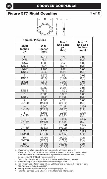
Nominal Pipe SizeMaxb
End Load psi
(bar)
Max.a, d End Gap Inches (mm)
ANSI Inches
DN
O.D. Inches (mm)
1DN5
1.315(33,7)
475(2,11)
0.06(1,5)
1-1/4DN32
1.660(42,4)
757(3,37)
0.06(1,5)
1-1/2DN40
1.900(48,3)
992(4,41)
0.06(1,5)
2DN50
2.375(60,3)
1,551(6,90)
0.06(1,5)
2-1/2DN65
2.875(73,0)
2,272(10,11)
0.06(1,5)
—DN65
3.000(76,1)
2,474(11,01)
0.06(1,5)
3DN80
3.500(88,9)
3,367(14,98)
0.06(1,5)
4DN100
4.500(114,3)
4,771(21,22)
0.06(1,5)
—DN125
5.500(139,7)
7,127(31,71)
0.125(3,2)
5DN125
5.563(141,3)
7,290(32,43)
0.125(3,2)
—DN150
6.500(165,1)
9,955(44,28)
0.125(3,2)
6DN150
6.625(168,3)
10,341(46,00)
0.125(3,2)
8DN200
8.625(219,1)
17,528(77,97)
0.125(3,2)
10e
DN25010.750(273,0)
27,229(121,0)
0.25(6,4)
12e
DN30012.750(323,9)
38,303(170,0)
0.25(6,4)
a. Maximum available gap between pipe ends. Minimum gap = 0.b. Maximum End Load are total from all loads based on standard weight steel
pipe. End loads may differ for other pipe materials and/or wall thickness. Contact your GRINNELL Representative.
c. Gold color coded metric bolts and nuts are available upon request.d. Max End Gap is for cut grooved standard weight pipe.e. For 10 inch and 12 inch sizes where VdS Approval is required, refer to Figure
772, Technical Data Sheet G140.• See Approved Pressure Ratings starting on page 125.• Refer to Technical Data Sheet TFP1854 for more information.
1 of 2Figure 577 Rigid Coupling
CB
A
45GROOVED COUPLINGS
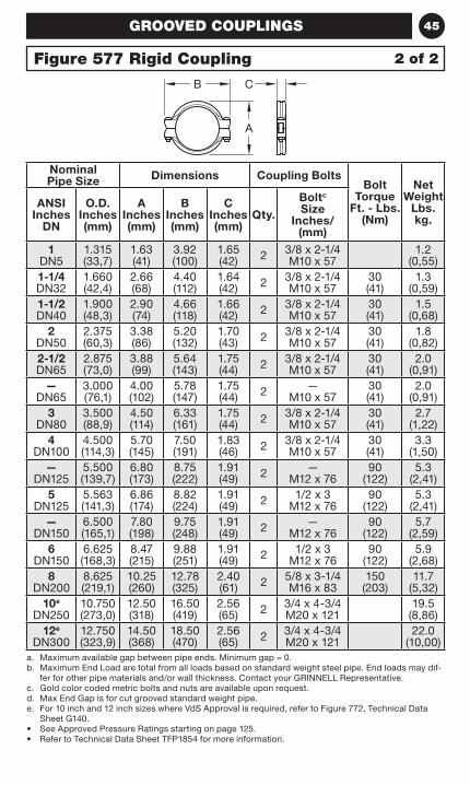
Nominal Pipe Size Dimensions Coupling Bolts
Bolt Torque
Ft. - Lbs. (Nm)
Net Weight
Lbs. kg.
ANSI Inches
DN
O.D. Inches (mm)
A Inches (mm)
B Inches (mm)
C Inches (mm)
Qty.
Boltc Size
Inches/(mm)
1DN5
1.315(33,7)
1.63(41)
3.92(100)
1.65(42) 2 3/8 x 2-1/4
M10 x 571.2
(0,55)1-1/4DN32
1.660(42,4)
2.66(68)
4.40(112)
1.64(42) 2 3/8 x 2-1/4
M10 x 5730(41)
1.3(0,59)
1-1/2DN40
1.900(48,3)
2.90(74)
4.66(118)
1.66(42) 2 3/8 x 2-1/4
M10 x 5730(41)
1.5(0,68)
2DN50
2.375(60,3)
3.38(86)
5.20(132)
1.70(43) 2 3/8 x 2-1/4
M10 x 5730(41)
1.8(0,82)
2-1/2DN65
2.875(73,0)
3.88(99)
5.64(143)
1.75(44) 2 3/8 x 2-1/4
M10 x 5730(41)
2.0(0,91)
—DN65
3.000(76,1)
4.00(102)
5.78(147)
1.75(44) 2 —
M10 x 5730(41)
2.0(0,91)
3DN80
3.500(88,9)
4.50(114)
6.33(161)
1.75(44) 2 3/8 x 2-1/4
M10 x 5730(41)
2.7 (1,22)
4DN100
4.500(114,3)
5.70(145)
7.50(191)
1.83(46) 2 3/8 x 2-1/4
M10 x 5730(41)
3.3(1,50)
—DN125
5.500(139,7)
6.80(173)
8.75(222)
1.91(49) 2 —
M12 x 7690
(122)5.3
(2,41)5
DN1255.563(141,3)
6.86(174)
8.82(224)
1.91(49) 2 1/2 x 3
M12 x 7690
(122)5.3
(2,41)—
DN1506.500 (165,1)
7.80(198)
9.75(248)
1.91(49) 2 —
M12 x 7690
(122)5.7
(2,59)6
DN1506.625(168,3)
8.47(215)
9.88(251)
1.91(49) 2 1/2 x 3
M12 x 7690
(122)5.9
(2,68)8
DN2008.625(219,1)
10.25(260)
12.78(325)
2.40(61) 2 5/8 x 3-1/4
M16 x 83150
(203)11.7
(5,32)10e
DN25010.750(273,0)
12.50(318)
16.50(419)
2.56(65) 2 3/4 x 4-3/4
M20 x 12119.5
(8,86)12e
DN30012.750(323,9)
14.50(368)
18.50(470)
2.56(65) 2 3/4 x 4-3/4
M20 x 12122.0
(10,00)a. Maximum available gap between pipe ends. Minimum gap = 0.b. Maximum End Load are total from all loads based on standard weight steel pipe. End loads may dif-
fer for other pipe materials and/or wall thickness. Contact your GRINNELL Representative.c. Gold color coded metric bolts and nuts are available upon request.d. Max End Gap is for cut grooved standard weight pipe.e. For 10 inch and 12 inch sizes where VdS Approval is required, refer to Figure 772, Technical Data
Sheet G140.• See Approved Pressure Ratings starting on page 125.• Refer to Technical Data Sheet TFP1854 for more information.
2 of 2Figure 577 Rigid Coupling
CB
A
46 GROOVED COUPLINGS
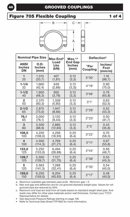
Nominal Pipe Size Max Endd Load Lbs (kN)
Max.a,b End Gap Inches (mm)
Deflectionb
ANSI Inches
DN
O.D. Inches (mm)
°Per Coupling
Inches/ Foot
(mm/m)
1 25
1.315(33,7)
407 (1,81)
0.13 (3,3) 5°30' 1.16
(96,7)
1-1/4 32
1.660(42,4)
649 (2,88)
0.13 (3,3)) 4°19' 0.90
(75,0)
1-1/2 40
1.900(48,3)
850 (3,78)
0.13 (3,3) 3°46' 0.79
(65,8)
2 50
2.375(60,3)
1,328 (5,90)
0.13 (3,3) 3°1' 0.63
(52,5)
2-1/2 65
2.875(73,0)
1,947 (8,66)
0.13 (3,3) 2°29' 0.52
(43,3)
76,1 65
3.000(76,1)
2,120 (9,43)
0.13 (3,3) 2°23' 0.50
(41,7)
3 80
3.500(88,9)
2,885 (12,83)
0.13 (3,3) 2°3' 0.43
(35,8)
108,0 100
4.250(108,0)
4,256 (18,93)
0.25 (6,4) 3°22' 0.70
(58,3)
4 100
4.500(114,3)
4,769 (21,21)
0.25 (6,4) 3°11' 0.67
(55,8)
133,0 125
5.250 (133,0)
6,494 (28,88)
0.25 (6,4) 2°44' 0.56
(46,7)
139,7 125
5.500 (139,7)
7,127 (31,70)
0.25 (6,4) 2°36' 0.55
(45,5)
5 125
5.563(141,3)
7,288 (32,41)
0.25 (6,4) 2°35' 0.54
(45,0)
159,0 150
6.250(159,0)
9,204 (40,93)
0.25 (6,4) 2°17' 0.48
(40,0)
a. Maximum available gap between pipe ends. Minimum gap = 0b. Max end gap and deflection are for cut grooved standard weight pipe. Values for roll
grooved pipe are reduced by 50%.c. Maximum end load are total from all loads based on standard weight steel pipe. End
loads may differ for other pipe materials and/or wall thickness. Contact your TYCO Representative for details.
• See Approved Pressure Ratings starting on page 128.• Refer to Technical Data Sheet TFP1820 for more information.
Figure 705 Flexible Coupling 1 of 4
B C
A
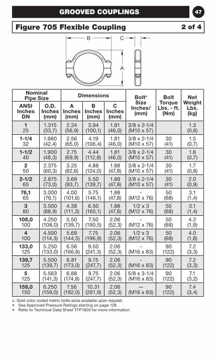
47GROOVED COUPLINGS
Nominal Pipe Size Dimensions Boltc
Size Inches/
(mm)
Bolt Torque
Lbs. - ft. (Nm)
Net Weight
Lbs. (kg)
ANSI Inches
DN
O.D. Inches (mm)
A Inches (mm)
B Inches (mm)
C Inches (mm)
1 25
1.315(33,7)
2.24 (56,9)
3.94 (100,1)
1.81 (46,0)
3/8 x 2-1/4 (M10 x 57)
1.3 (0,6)
1-1/4 32
1.660(42,4)
2.56(65,0)
4.19(106,4)
1.81(46,0)
3/8 x 2-1/4 (M10 x 57)
30(41)
1.5(0,7)
1-1/2 40
1.900(48,3)
2.75 (69,9)
4.44(112,8)
1.81(46,0)
3/8 x 2-1/4 (M10 x 57)
30(41)
1.6(0,7)
2 50
2.375(60,3)
3.25(82,6)
4.88(124,0)
1.88(47,8)
3/8 x 2-1/4 (M10 x 57)
30(41)
1.7(0,8)
2-1/2 65
2.875(73,0)
3.69 (93,7)
5.50(139,7)
1.88(47,8)
3/8 x 2-1/4 (M10 x 57)
30(41)
2.0 (0,9)
76,1 65
3.000(76,1)
4.00 (101,6)
5.75(146,1)
1.88 (47,8)
- (M12 x 76)
50(68)
3.1 (1,4)
3 80
3.500(88,9)
4.38(111,3)
6.50(165,1)
1.88(47,8)
1/2 x 3 (M12 x 76)
50(68)
3.1 (1,4)
108,0 100
4.250(108,0)
5.50 (139,7)
7.50 (190,5)
2.06(52,3)
- (M12 x 76)
50(68)
4.2(1,9)
4 100
4.500(114,3)
5.69(144,5)
7.75(196,9)
2.06(52,3)
1/2 x 3 (M12 x 76)
50(68)
4.0 (1,8)
133,0 125
5.250 (133,0)
6.56 (166,6)
9.50 (241,3)
2.06 (52,3)
- (M16 x 83)
90 (122)
7.2 (3,3)
139,7 125
5.500 (139,7)
6.81 (173,0)
9.75 (247,7)
2.06 (52,3)
- (M16 x 83)
90 (122)
7.2 (3,3)
5 125
5.563(141,3)
6.88(174,8)
9.75(247,7)
2.06(52,3)
5/8 x 3-1/4 (M16 x 83)
90(122)
7.1 (3,2)
159,0 150
6.250(159,0)
7.56 (192,0)
10.31 (261,9)
2.06(52,3)
—(M16 x 83)
90(122)
7.4 (3,4)
c. Gold color coded metric bolts sizes available upon request. • See Approved Pressure Ratings starting on page 128.• Refer to Technical Data Sheet TFP1820 for more information.
2 of 4Figure 705 Flexible CouplingB C
A
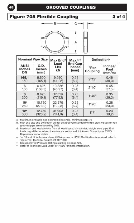
48 GROOVED COUPLINGS
Nominal Pipe Size Max Endd Load Lbs kN
Max.a, b End Gap Inches (mm)
Deflectionb
ANSI Inches
DN
O.D. Inches (mm)
°Per Coupling
Inches/ Foot
(mm/m)165,1 150
6.500(165,1)
9,950 (44,25)
0.25 (6,4) 2°12' 0.46
(38,3)
6 150
6.625(168,3)
10,336 (45,97)
0.25(6,4) 2°10' 0.45
(37,5)
8 200
8.625(219,1)
17,519 (77,92)
0.25(6,4) 1°40' 0.35
(29,2)
10e 250
10.750(273,0)
22,679 (100,8)
0.25(6,4) 1°20' 0.28
(23,3)
12e 300
12.750(323,9)
31,903 (141,9)
0.25(6,4) 1°7' 0.23
(19,2)
a. Maximum available gap between pipe ends. Minimum gap = 0b. Max end gap and deflection are for cut grooved standard weight pipe. Values for roll
grooved pipe are reduced by 50%.d. Maximum end load are total from all loads based on standard weight steel pipe. End
loads may differ for other pipe materials and/or wall thickness. Contact your TYCO Representative for details.
e. For 10 and 12 inch sizes where VdS Approval or LPCB Certification is required, refer to Figure 707, Technical data Sheet TFP1840.
• See Approved Pressure Ratings starting on page 128.• Refer to Technical Data Sheet TFP1820 for more information.
Figure 705 Flexible Coupling 3 of 4
B C
A
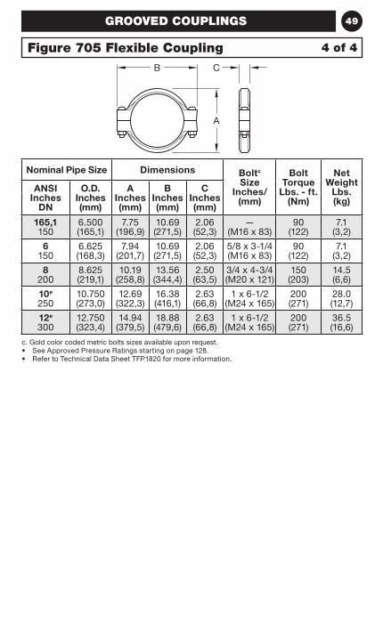
49GROOVED COUPLINGS
Nominal Pipe Size Dimensions Boltc Size
Inches/(mm)
Bolt Torque
Lbs. - ft. (Nm)
Net Weight
Lbs. (kg)
ANSI Inches
DN
O.D. Inches (mm)
A Inches (mm)
B Inches (mm)
C Inches (mm)
165,1 150
6.500(165,1)
7.75(196,9)
10.69(271,5)
2.06(52,3)
— (M16 x 83)
90(122)
7.1 (3,2)
6 150
6.625(168,3)
7.94 (201,7)
10.69(271,5)
2.06(52,3)
5/8 x 3-1/4 (M16 x 83)
90(122)
7.1 (3,2)
8 200
8.625(219,1)
10.19 (258,8)
13.56(344,4)
2.50(63,5)
3/4 x 4-3/4 (M20 x 121)
150(203)
14.5 (6,6)
10e 250
10.750(273,0)
12.69(322,3)
16.38(416,1)
2.63(66,8)
1 x 6-1/2 (M24 x 165)
200(271)
28.0 (12,7)
12e 300
12.750(323,4)
14.94(379,5)
18.88(479,6)
2.63(66,8)
1 x 6-1/2 (M24 x 165)
200(271)
36.5 (16,6)
c. Gold color coded metric bolts sizes available upon request.• See Approved Pressure Ratings starting on page 128.• Refer to Technical Data Sheet TFP1820 for more information.
Figure 705 Flexible Coupling 4 of 4
B C
A
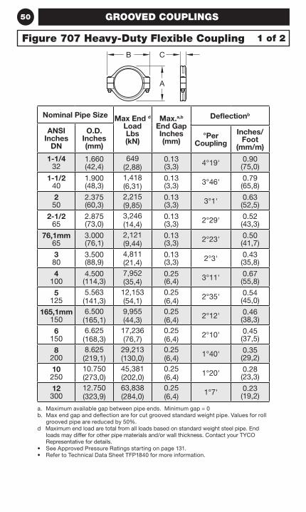
50
Nominal Pipe Size Max End d Load Lbs (kN)
Max.a,b End Gap Inches (mm)
Deflectionb
ANSI Inches
DN
O.D. Inches (mm)
°Per Coupling
Inches/ Foot
(mm/m)
1-1/4 32
1.660(42,4)
649 (2,88)
0.13(3,3) 4°19' 0.90
(75,0)
1-1/2 40
1.900(48,3)
1,418 (6,31)
0.13(3,3) 3°46' 0.79
(65,8)
2 50
2.375(60,3)
2,215 (9,85)
0.13(3,3) 3°1' 0.63
(52,5)
2-1/2 65
2.875(73,0)
3,246 (14,4)
0.13(3,3) 2°29' 0.52
(43,3)
76,1mm 65
3.000(76,1)
2,121 (9,44)
0.13(3,3) 2°23' 0.50
(41,7)
3 80
3.500(88,9)
4,811 (21,4)
0.13(3,3) 2°3' 0.43
(35,8)
4 100
4.500(114,3)
7,952 (35,4)
0.25(6,4) 3°11' 0.67
(55,8)
5 125
5.563 (141,3)
12,153 (54,1)
0.25 (6,4) 2°35' 0.54
(45,0)
165,1mm 150
6.500 (165,1)
9,955 (44,3)
0.25 (6,4) 2°12' 0.46
(38,3)
6 150
6.625 (168,3)
17,236 (76,7)
0.25 (6,4) 2°10' 0.45
(37,5)
8 200
8.625 (219,1)
29,213 (130,0)
0.25 (6,4) 1°40' 0.35
(29,2)
10 250
10.750 (273,0)
45,381 (202,0)
0.25 (6,4) 1°20' 0.28
(23,3)
12 300
12.750 (323,9)
63,838 (284,0)
0.25 (6,4) 1°7' 0.23
(19,2)
a. Maximum available gap between pipe ends. Minimum gap = 0b. Max end gap and deflection are for cut grooved standard weight pipe. Values for roll
grooved pipe are reduced by 50%.d Maximum end load are total from all loads based on standard weight steel pipe. End
loads may differ for other pipe materials and/or wall thickness. Contact your TYCO Representative for details.
• See Approved Pressure Ratings starting on page 131.• Refer to Technical Data Sheet TFP1840 for more information.
GROOVED COUPLINGS
1 of 2Figure 707 Heavy-Duty Flexible Coupling
CB
A
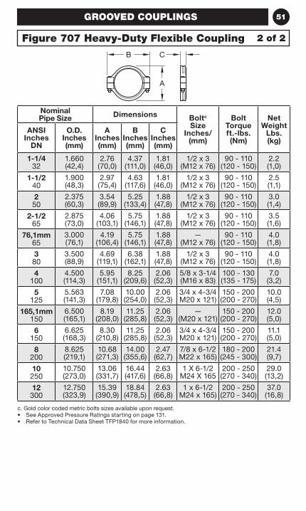
51
Nominal Pipe Size Dimensions Boltc
Size Inches/
(mm)
Bolt Torque ft.-lbs. (Nm)
Net Weight
Lbs. (kg)
ANSI Inches
DN
O.D. Inches (mm)
A Inches (mm)
B Inches (mm)
C Inches (mm)
1-1/4 32
1.660(42,4)
2.76(70,0)
4.37(111,0)
1.81(46,0)
1/2 x 3 (M12 x 76)
90 - 110(120 - 150)
2.2(1,0)
1-1/2 40
1.900(48,3)
2.97 (75,4)
4.63(117,6)
1.81(46,0)
1/2 x 3 (M12 x 76)
90 - 110(120 - 150)
2.5(1,1)
2 50
2.375(60,3)
3.54(89,9)
5.25(133,4)
1.88(47,8)
1/2 x 3 (M12 x 76)
90 - 110(120 - 150)
3.0 (1,4)
2-1/2 65
2.875(73,0)
4.06 (103,1)
5.75(146,1)
1.88(47,8)
1/2 x 3 (M12 x 76)
90 - 110(120 - 150)
3.5 (1,6)
76,1mm 65
3.000(76,1)
4.19 (106,4)
5.75(146,1)
1.88 (47,8)
— (M12 x 76)
90 - 110(120 - 150)
4.0 (1,8)
3 80
3.500(88,9)
4.69(119,1)
6.38(162,1)
1.88(47,8)
1/2 x 3 (M12 x 76)
90 - 110(120 - 150)
4.0 (1,8)
4 100
4.500(114,3)
5.95(151,1)
8.25(209,6)
2.06(52,3)
5/8 x 3-1/4 (M16 x 83)
100 - 130(135 - 175)
7.0 (3,2)
5 125
5.563 (141,3)
7.08 (179,8)
10.00 (254,0)
2.06 (52,3)
3/4 x 4-3/4 M20 x 121)
150 - 200 (200 - 270)
10.0 (4,5)
165,1mm 150
6.500 (165,1)
8.19 (208,0)
11.25 (285,8)
2.06 (52,3)
— (M20 x 121)
150 - 200 (200 - 270)
12.0 (5,0)
6 150
6.625 (168,3)
8.30 (210,8)
11.25 (285,8)
2.06 (52,3)
3/4 x 4-3/4 M20 x 121)
150 - 200 (200 - 270)
11.1 (5,0)
8 200
8.625 (219,1)
10.68 (271,3)
14.00 (355,6)
2.47 (62,7)
7/8 x 6-1/2 M22 x 165)
180 - 200 (245 - 300)
21.4 (9,7)
10 250
10.750 (273,0)
13.06 (331,7)
16.44 (417,6)
2.63 (66,8)
1 X 6-1/2 M24 X 165
200 - 250 (270 - 340)
29.0 (13,2)
12 300
12.750 (323,9)
15.39 (390,9)
18.84 (478,5)
2.63 (66,8)
1 x 6-1/2 M24 x 165)
200 - 250 (270 - 340)
37.0 (16,8)
c. Gold color coded metric bolts sizes available upon request.• See Approved Pressure Ratings starting on page 131.• Refer to Technical Data Sheet TFP1840 for more information.
GROOVED COUPLINGS
2 of 2Figure 707 Heavy-Duty Flexible Coupling
CB
A
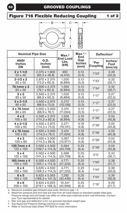
52
Nominal Pipe Size Max.b End Load
Lbs. (kN)
Max.a, c End Gap
Inches (mm)
Deflectionc
ANSI Inches
DN
O.D. Inches (mm)
ºPer Coupling
Inches/ Foot
(mm/m)
2 x 1-1/2 50 x 40
2.375 x 1.900 (60,3 x 48,8)
992 (4,412)
0.13 (3,3) 1°53’ 0.39
(32,5)2-1/2 x 2 65 x 50
2.875 x 2.375 (73,0 x 60,3)
1,550 (6,894)
0.13 (3,3) 1°33’ 0.32
(26,7)76.1mm x 2
65 x 503.000 x 2.375 (76,1 x 60,3)
1,550 (6,894)
0.13 (3,3) 1°34’ 0.32
(26,7)3 x 2
80 x 503.500 x 2.375 (88,9 x 60,3)
1,550 (6,894)
0.13 (3,3) 1°17’ 0.27
(22,5)3 x 2-1/2 80 x 65
3.500 x 2.875 (88,9 x 73,0)
2,272 (10,106)
0.13 (3,3) 1°17’ 0.27
(22,5)3 x 76.1mm
80 x 653.500 x 3.000 (88,9 x 76,1)
2,474 (11,004)
0.13 (3,3) 1°17’ 0.27
(22,5)4 x 2
100 x 504.500 x 2.375 (114,3 x 60,3)
1,550 (6,894)
0.19 (4,8) 2°38’ 0.55
(45,8)4 x 2-1/2 100 x 65
4.500 x 2.875 (114,3 x 73,0)
2.271 (10,101)
0.19 (4,8) 2°38’ 0.55
(45,8)4 x 76.1mm
100 x 654.500 x 3.000 (114,3 x 76,1)
2,474 (11,004)
0.19 (4,8) 2°38’ 0.55
(45,8)4 x 3
100 x 804.500 x 3.500 (114,3 x 88,9)
3,367 (14,977)
0.19 (4,8) 2°38’ 0.55
(45,8)139.7mm x 4
125 x 1005.500 x 4.500 (139,7 x 114,3)
5,564 (24,749)
0.25 (6,4) 2°38’ 0.55
(45,8)5 x 4
125 x 1005.563 x 4.500 (141,3 x 114,3)
5,566 (24,759)
0.25 (6,4) 2°5’ 0.44
(36,7)165.1mm x 4
150 x 1006.500 x 4.500 (165,1 x 114,3)
4,771 (21,222)
0.25 (6,4) 1°50’ 0.38
(31,7)6 x 4
150 x 1006.625 x 4.500 (168,3 x 114,3)
4,771 (21,222)
0.25 (6,4) 1°44’ 0.36
(30,0)6 x 5
150 x 1256.625 x 5.563 (168,3 x 141,3)
7,292 (32,436)
0.25 (6,4) 1°44’ 0.36
(30,0)8 x 6
200 x 1508.625 x 6.625 (219,1 x 168,3)
10,341 (45,999)
0.25 (6,4) 1°15’ 0.26
(21,7)a. Maximum available gap between pipe ends. Minimum gap = 0b. Maximum pressure and end load are total from all loads based on standard weight steel pipe.
Pressure ratings and end loads may differ on other pipe materials and/or wall thickness. Contact your Tyco representative for details.
c. Max end gap and deflection is for cut grooved standard weight pipe.• See Approved Pressure Ratings starting on page 134.• Refer to Technical Data Sheet TFP1820 for more information.
GROOVED COUPLINGS
1 of 2Figure 716 Flexible Reducing Coupling
B
A
C
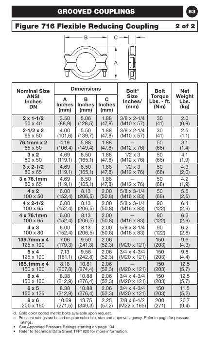
53
Nominal Size ANSI
Inches DN
Dimensions Boltd Size
Inches/(mm)
Bolt Torque
Lbs. - ft. (Nm)
Net Weight
Lbs. (kg)
A Inches (mm)
B Inches (mm)
C Inches (mm)
2 x 1-1/2 50 x 40
3.50 (88,9)
5.06 (128,5)
1.88 (47,8)
3/8 x 2-1/4 (M10 x 57)
30 (41)
2.0 (0,9)
2-1/2 x 2 65 x 50
4.00 (101,6)
5.50 (139,7)
1.88 (47,8)
3/8 x 2-1/4 (M10 x 57)
30 (41)
2.5 (1,1)
76.1mm x 2 65 x 50
4.19 (106,4)
5.88 (149,4)
1.88 (47,8)
— (M12 x 76)
50 (68)
3.1 (1.4)
3 x 2 80 x 50
4.69 (119,1)
6.50 (165,1)
1.88 (47,8)
1/2 x 3 (M12 x 76)
50 (68)
4.1 (1,9)
3 x 2-1/2 80 x 65
4.69 (119,1)
6.50 (165,1)
1.88 (47,8)
1/2 x 3 (M12 x 76)
50 (68)
4.3 (2,0)
3 x 76.1mm 80 x 65
4.69 (119,1)
6.50 (165,1)
1.88 (47,8)
— (M12 x 76)
50 (68)
4.2 (1,9)
4 x 2 100 x 50
6.00 (152,4)
8.13 (206,5)
2.00 (50,8)
5/8 x 3-1/4 (M16 x 83)
50 (68)
5.5 (2,5)
4 x 2-1/2 100 x 65
6.00 (152,4)
8.13 (206,5)
2.00 (50,8)
5/8 x 3-1/4 (M16 x 83)
90 (122)
6.4 (2,9)
4 x 76.1mm 100 x 65
6.00 (152,4)
8.13 (206,5)
2.00 (50,8)
— (M16 x 83)
90 (122)
6.3 (2,9)
4 x 3 100 x 80
6.00 (152,4)
8.13 (206,5)
2.00 (50,8)
5/8 x 3-1/4 (M16 x 83)
90 (122)
6.2 (2,8)
139.7mm x 4 125 x 100
7.06 (179,3)
9.50 (241,3)
2.06 (52,3)
— (M20 x 121)
150 (203)
9.6 (4,3)
5 x 4 125 x 100
7.13 (181,1)
9.56 (242,8)
2.06 (52,3)
3/4 x 4-3/4 (M20 x 121)
150 (203)
9.8 (4,4)
165.1mm x 4 150 x 100
8.18 (207,8)
10.81 (274,4)
2.06 (52,3)
— (M20 x 121)
150 (203)
12.5 (5,7)
6 x 4 150 x 100
8.38 (212,9)
10.88 (276,4)
2.06 (52,3)
3/4 x 4-3/4 (M20 x 121)
150 (203)
12.5 (5,7)
6 x 5 150 x 125
8.38 (212,9)
10.88 (276,4)
2.06 (52,3)
3/4 x 4-3/4 (M20 x 121)
150 (203)
11.5 (5,2)
8 x 6 200 x 150
10.69 (271,5)
13.75 (349,3)
2.25 (57,2)
7/8 x 6-1/2 (M22 x 165)
200 (271)
20.7 (9,4)
d. Gold color coded metric bolts available upon request.e. Pressure ratings are based on pipe schedule, size and approval agency. Refer to page for pressure
ratings.• See Approved Pressure Ratings starting on page 134.• Refer to Technical Data Sheet TFP1820 for more information.
GROOVED COUPLINGS
2 of 2Figure 716 Flexible Reducing Coupling
B
A
C
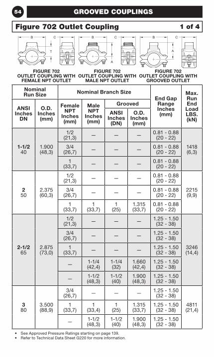
54
Nominal Run Size Nominal Branch Size
End Gap Range Inches (mm)
Max. Run End Load LBS. (kN)
ANSI Inches
DN
O.D. Inches (mm)
Female NPT
Inches (mm)
Male NPT
Inches (mm)
Grooved
ANSI Inches
(DN)
O.D. Inches (mm)
1-1/2 40
1.900 (48,3)
1/2 (21,3) — — — 0.81 - 0.88
(20 - 22)
1418 (6,3)
3/4 (26,7) — — — 0.81 - 0.88
(20 - 22)
1 (33,7) — — — 0.81 - 0.88
(20 - 22)
2 50
2.375 (60,3)
1/2 (21,3) — — — 0.81 - 0.88
(20 - 22)
2215 (9,9)
3/4 (26,7) — — — 0.81 - 0.88
(20 - 22)
1 (33,7)
1 (33,7)
1 (25)
1.315 (33,7)
0.81 - 0.88 (20 - 22)
2-1/2 65
2.875 (73,0)
1/2 (21,3) — — — 1.25 - 1.50
(32 - 38)
3246 (14,4)
3/4 (26,7) — — — 1.25 - 1.50
(32 - 38)
1 (33,7) — — — 1.25 - 1.50
(32 - 38)
— 1-1/4 (42,4)
1-1/4 (32)
1.660 (42,4)
1.25 - 1.50 (32 - 38)
— 1-1/2 (48,3)
1-1/2 (40)
1.900 (48,3)
1.25 - 1.50 (32 - 38)
3 80
3.500 (88,9)
3/4 (26,7) — — — 1.25 - 1.50
(32 - 38)
4811 (21,4)
1 (33,7)
1 (33,4)
1 (25)
1.315 (33,7)
1.25 - 1.50 (32 - 38)
— 1-1/2 (48,3)
1-1/2 (40)
1.900 (48,3)
1.25 - 1.50 (32 - 38)
• See Approved Pressure Ratings starting on page 139.• Refer to Technical Data Sheet G220 for more information.
GROOVED COUPLINGS
1 of 4Figure 702 Outlet Coupling
FIGURE 702 OUTLET COUPLING WITH
FEMALE NPT OUTLET
FIGURE 702 OUTLET COUPLING WITH
MALE NPT OUTLET
FIGURE 702 OUTLET COUPLING WITH
GROOVED OUTLET
CB
T
A
CB CB
A
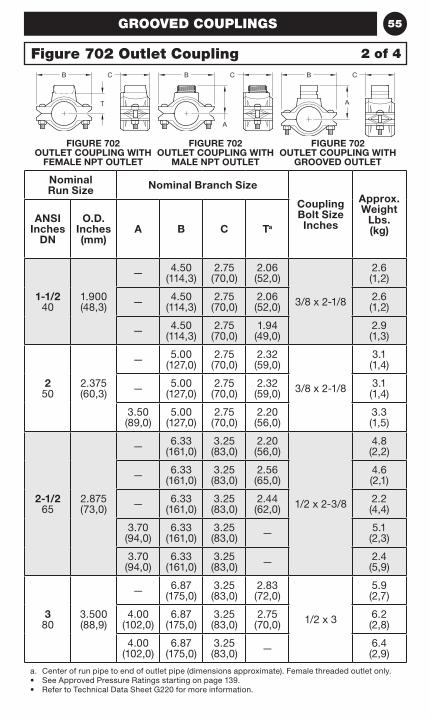
55
Nominal Run Size Nominal Branch Size
Coupling Bolt Size Inches
Approx. Weight
Lbs. (kg)
ANSI Inches
DN
O.D. Inches (mm)
A B C Ta
1-1/2 40
1.900 (48,3)
— 4.50 (114,3)
2.75 (70,0)
2.06 (52,0)
3/8 x 2-1/8
2.6 (1,2)
— 4.50 (114,3)
2.75 (70,0)
2.06 (52,0)
2.6 (1,2)
— 4.50 (114,3)
2.75 (70,0)
1.94 (49,0)
2.9 (1,3)
2 50
2.375 (60,3)
— 5.00 (127,0)
2.75 (70,0)
2.32 (59,0)
3/8 x 2-1/8
3.1 (1,4)
— 5.00 (127,0)
2.75 (70,0)
2.32 (59,0)
3.1 (1,4)
3.50 (89,0)
5.00 (127,0)
2.75 (70,0)
2.20 (56,0)
3.3 (1,5)
2-1/2 65
2.875 (73,0)
— 6.33 (161,0)
3.25 (83,0)
2.20 (56,0)
1/2 x 2-3/8
4.8 (2,2)
— 6.33 (161,0)
3.25 (83,0)
2.56 (65,0)
4.6 (2,1)
— 6.33 (161,0)
3.25 (83,0)
2.44 (62,0)
2.2 (4,4)
3.70 (94,0)
6.33 (161,0)
3.25 (83,0) — 5.1
(2,3)
3.70 (94,0)
6.33 (161,0)
3.25 (83,0) — 2.4
(5,9)
3 80
3.500 (88,9)
— 6.87 (175,0)
3.25 (83,0)
2.83 (72,0)
1/2 x 3
5.9 (2,7)
4.00 (102,0)
6.87 (175,0)
3.25 (83,0)
2.75 (70,0)
6.2 (2,8)
4.00 (102,0)
6.87 (175,0)
3.25 (83,0) — 6.4
(2,9)
a. Center of run pipe to end of outlet pipe (dimensions approximate). Female threaded outlet only.• See Approved Pressure Ratings starting on page 139.• Refer to Technical Data Sheet G220 for more information.
GROOVED COUPLINGS
2 of 4Figure 702 Outlet Coupling
FIGURE 702 OUTLET COUPLING WITH
FEMALE NPT OUTLET
FIGURE 702 OUTLET COUPLING WITH
MALE NPT OUTLET
FIGURE 702 OUTLET COUPLING WITH
GROOVED OUTLET
CB
T
A
CB CB
A
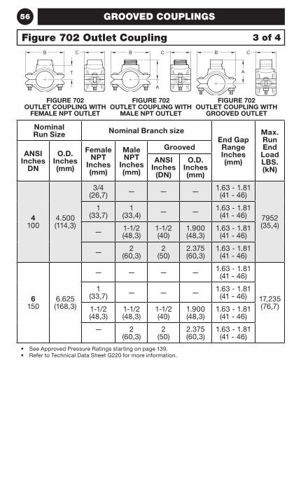
56
Nominal Run Size Nominal Branch size
End Gap Range Inches (mm)
Max. Run End Load LBS. (kN)
ANSI Inches
DN
O.D. Inches (mm)
Female NPT
Inches (mm)
Male NPT
Inches (mm)
Grooved
ANSI Inches
(DN)
O.D. Inches (mm)
4 100
4.500 (114,3)
3/4 (26,7) — — — 1.63 - 1.81
(41 - 46)
7952 (35,4)
1 (33,7)
1 (33,4) — — 1.63 - 1.81
(41 - 46)
— 1-1/2 (48,3)
1-1/2 (40)
1.900 (48,3)
1.63 - 1.81 (41 - 46)
— 2 (60,3)
2 (50)
2.375 (60,3)
1.63 - 1.81 (41 - 46)
6 150
6.625 (168,3)
— — — — 1.63 - 1.81 (41 - 46)
17,235 (76,7)
1 (33,7) — — — 1.63 - 1.81
(41 - 46)
1-1/2 (48,3)
1-1/2 (48,3)
1-1/2 (40)
1.900 (48,3)
1.63 - 1.81 (41 - 46)
— 2 (60,3)
2 (50)
2.375 (60,3)
1.63 - 1.81 (41 - 46)
• See Approved Pressure Ratings starting on page 139.• Refer to Technical Data Sheet G220 for more information.
GROOVED COUPLINGS
3 of 4Figure 702 Outlet Coupling
FIGURE 702 OUTLET COUPLING WITH
FEMALE NPT OUTLET
FIGURE 702 OUTLET COUPLING WITH
MALE NPT OUTLET
FIGURE 702 OUTLET COUPLING WITH
GROOVED OUTLET
CB
T
A
CB CB
A
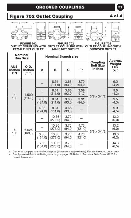
57
Nominal Run Size Nominal Branch size
Coupling Bolt Size Inches
Approx. Weight
Lbs. (kg)
ANSI Inches
DN
O.D. Inches (mm)
A B C Ta
4 100
4.500 (114,3)
— 8.31 (211,0)
3.66 (93,0)
3.70 (94,0)
5/8 x 3-1/2
9.2 (4,2)
— 8.31 (211,0)
3.66 (93,0)
3.58 (91,0)
9.5 (4,3)
4.88 (124,0)
8.31 (211,0)
3.66 (93,0)
3.31 (84,0)
9.5 (4,3)
4.88 (124,0)
8.31 (211,0)
3.66 (93,0) — 9.9
(4,5)
6 150
6.625 (168,3)
— 10.86 (276,0)
3.70 (94,0) —
5/8 x 3-1/2
13.2 (6,0)
— 10.86 (276,0)
3.70 (94,0)
4.76 (121,0)
13.2 (6,0)
6.06 (154,0)
10.86 (276,0)
3.70 (94,0)
4.76 (121,0)
13.6 (6,2)
6.06 (154,0)
10.86 (276,0)
3.70 (94,0) — 14.3
(6,5)
a. Center of run pipe to end of outlet pipe (dimensions approximate). Female threaded outlet only.• See Approved Pressure Ratings starting on page 139.Refer to Technical Data Sheet G220 for
more information.
GROOVED COUPLINGS
4 of 4Figure 702 Outlet Coupling
FIGURE 702 OUTLET COUPLING WITH
FEMALE NPT OUTLET
FIGURE 702 OUTLET COUPLING WITH
MALE NPT OUTLET
FIGURE 702 OUTLET COUPLING WITH
GROOVED OUTLET
CB
T
A
CB CB
A

58 NOTES
59FLANGE ADAPTERS
FlangeAdapters
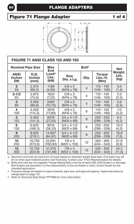
60 FLANGE ADAPTERS
FIGURE 71 ANSI CLASS 125 AND 150
Nominal Pipe Size Max End
Loada Lbs. (kN)
BoltbNet
Weight. Lbs. (kg)
ANSI Inches
DN
O.D. Inches (mm)
Size Dia. x Lg. Qty.
Torque Lbs.-ft.
(Nm)
2 50
2.375 (60,3)
1108 (4,93)
5/8 x 3 (M16 x 76) 4 110 - 140
(149 - 190)3.0(1,4)
2-1/2 65
2.875(73,0)
1623 (7,22)
5/8 x 3 (M16 x 76) 4 110 - 140
(149 - 190)5.0(2,3)
3 80
3.500(88,9)
2405 (10,70)
5/8 x 3 (M16 x 76) 4 110 - 140
(149 - 190)5.6(2,5)
4 100
4.500(114,3)
3976 (17,69)
5/8 x 3 (M16 x 76) 8 110 - 140
(149 - 190)7.0
(3,2)5
1255.563(141,3)
6076 (27,03)
3/4 x 3-1/2 (M20 x 89) 8 220 - 250
(298 - 339)9.2(4,2)
6 150
6.625(168,3)
8618 (38,33)
3/4 x 3-1/2 (M20 x 89) 8 220 - 250
(298 - 339)10.0(4,5)
8 200
8.625(219,1)
14,607 (64,97)
3/4 x 3-1/2 (M20 x 89) 8 220 - 250
(298 - 339)16.6(7,5)
10 250
10.750(273,0)
22,691 (100,93)
7/8 x 4 (M22 x 102) 12 320 - 400
(434 - 542)21.8(9,9)
12 300
12.750(323,9)
31,919 (141,98)
7/8 x 4 (M22 x 102) 12 320 - 400
(434 - 542)24.2(11,0)
a. Maximum end load are total form all loads based on standard weight steel pipe. End loads may dif-fer on other pipe materials and/or wall thickness. Contact your TYCO Representative for details.
b. Bolts and nuts are not supplied. Flange Mating Bolts must be at least SAE J429 Grade 5 or stronger. Bolt lengths are standard; it is the responsibility of the purchaser to verify correct length for the intended application.
• Pressure ratings are based on pipe schedule, pipe size, and approval agency. Approved pressure ratings start on page 137.
• Refer to Technical Data Sheet TFP1880 for more information.
Figure 71 Flange Adapter 1 of 4
Size 2" (DN50) - 12" (DN300)
CA
F B E D
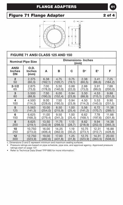
61FLANGE ADAPTERS
FIGURE 71 ANSI CLASS 125 AND 150
Nominal Pipe Size Dimensions- Inches (mm)
ANSI Inches
DN
O.D. Inches (mm)
A B C Dc Ec F
2 50
2.375 (60,3)
6.38(162,1)
4.75(120,7)
0.75(19,1)
2.38(60,5)
3.41(86,6)
7.25(184,2)
2-1/2 65
2.875(73,0)
7.00(178,0)
5.50(140,0)
0.88(22,0)
2.88(73,0)
3.91(99,0)
7.88(200,0)
3 80
3.500(88,9)
7.50(190,5)
6.00(152,4)
0.94(23,9)
3.50(88,9)
4.53(115,1)
9.88(251,0)
4 100
4.500(114,3)
9.00(228,6)
7.50(190,5)
0.94(23,9)
4.50(114,3)
5.53(140,5)
9.90(251,5)
5 125
5.563(141,3)
10.00(254,0)
8.50(215,9)
1.00(25,4)
5.56(141,2)
6.72(170,7)
11.38(289,1)
6 150
6.625(168,3)
11.00(279,4)
9.50(241,3)
1.00(25,4)
6.62(168,1)
7.78(197,6)
11.88(301,8)
8 200
8.625(219,1)
13.50(342,9)
11.75(298,5)
1.13(28,7)
8.62(218,9)
9.94(252,5)
14.38(365,3)
10 250
10.750(273,0)
16.00(406,4)
14.25(362,0)
1.19(30,2)
10.75(273,1)
12.31(312,7)
16.88(428,8)
12 300
12.750(323,9)
19.00(482,6)
17.00(431,8)
1.25(31,8)
12.75(323,9)
14.31(363,5)
20.00(508,0)
c. Dimensions D and E represent minimum and maximum sealing surfaces.• Pressure ratings are based on pipe schedule, pipe size, and approval agency. Approved pressure
ratings start on page 137.• Refer to Technical Data Sheet TFP1880 for more information.
2 of 4Figure 71 Flange Adapter
Size 2" (DN50) - 12" (DN300)
CA
F B E D
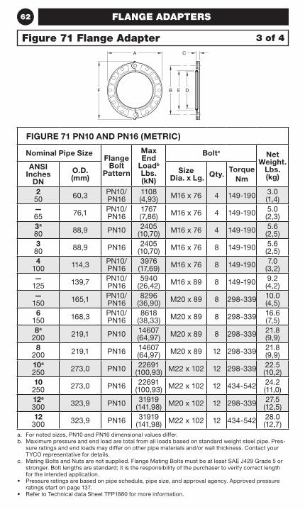
62 FLANGE ADAPTERS
FIGURE 71 PN10 AND PN16 (METRIC)
Nominal Pipe SizeFlange
Bolt Pattern
Max End
Loadb Lbs. (kN)
Boltc Net Weight.
Lbs. (kg)
ANSI Inches
DN
O.D. (mm)
Size Dia. x Lg. Qty.
TorqueNm
2 50 60,3 PN10/
PN161108 (4,93) M16 x 76 4 149-190 3.0
(1,4)— 65 76,1 PN10/
PN161767 (7,86) M16 x 76 4 149-190 5.0
(2,3)3a 80 88,9 PN10 2405
(10,70) M16 x 76 4 149-190 5.6(2,5)
3 80 88,9 PN16 2405
(10,70) M16 x 76 8 149-190 5.6(2,5)
4 100 114,3 PN10/
PN163976
(17,69) M16 x 76 8 149-190 7.0(3,2)
— 125 139,7 PN10/
PN165940
(26,42) M16 x 89 8 149-190 9.2(4,2)
— 150 165,1 PN10/
PN168296
(36,90) M20 x 89 8 298-339 10.0(4,5)
6 150 168,3 PN10/
PN168618
(38,33) M20 x 89 8 298-339 16.6(7,5)
8a 200 219,1 PN10 14607
(64,97) M20 x 89 8 298-339 21.8(9,9)
8 200 219,1 PN16 14607
(64,97) M20 x 89 12 298-339 21.8(9,9)
10a 250 273,0 PN10 22691
(100,93) M22 x 102 12 298-339 22.5(10,2)
10 250 273,0 PN16 22691
(100,93) M22 x 102 12 434-542 24.2(11,0)
12a 300 323,9 PN10 31919
(141,98) M20 x 102 12 298-339 27.5 (12,5)
12 300 323,9 PN16 31919
(141,98) M22 x 102 12 434-542 28.0 (12,7)
a. For noted sizes, PN10 and PN16 dimensional values differ.b. Maximum pressure and end load are total from all loads based on standard weight steel pipe. Pres-
sure ratings and end loads may differ on other pipe materials and/or wall thickness. Contact your TYCO representative for details.
c. Mating Bolts and Nuts are not supplied. Flange Mating Bolts must be at least SAE J429 Grade 5 or stronger. Bolt lengths are standard; it is the responsibility of the purchaser to verify correct length for the intended application.
• Pressure ratings are based on pipe schedule, pipe size, and approval agency. Approved pressure ratings start on page 137.
• Refer to Technical data Sheet TFP1880 for more information.
3 of 4Figure 71 Flange Adapter
Size 2" (DN50) - 12" (DN300)
CA
F B E D
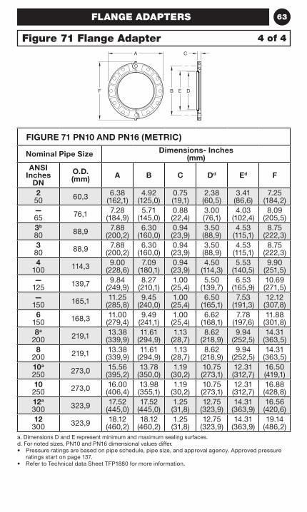
63FLANGE ADAPTERS
FIGURE 71 PN10 AND PN16 (METRIC)
Nominal Pipe Size Dimensions- Inches (mm)
ANSI Inches
DN
O.D. (mm) A B C Dd Ed F
2 50 60,3 6.38
(162,1)4.92
(125,0)0.75 (19,1)
2.38 (60,5)
3.41 (86,6)
7.25 (184,2)
— 65 76,1 7.28
(184,9)5.71
(145,0)0.88 (22,4)
3.00 (76,1)
4.03 (102,4)
8.09 (205,5)
3b 80 88,9 7.88
(200,2)6.30
(160,0)0.94 (23,9)
3.50 (88,9)
4.53 (115,1)
8.75 (222,3)
3 80 88,9 7.88
(200,2)6.30
(160,0)0.94 (23,9)
3.50 (88,9)
4.53 (115,1)
8.75 (222,3)
4 100 114,3 9.00
(228,6)7.09
(180,1)0.94 (23,9)
4.50 (114,3)
5.53 (140,5)
9.90 (251,5)
— 125 139,7 9.84
(249,9)8.27
(210,1)1.00 (25,4)
5.50 (139,7)
6.53 (165,9)
10.69 (271,5)
— 150 165,1 11.25
(285,8)9.45
(240,0)1.00 (25,4)
6.50 (165,1)
7.53 (191,3)
12.12 (307,8)
6 150 168,3 11.00
(279,4)9.49
(241,1)1.00 (25,4)
6.62 (168,1)
7.78 (197,6)
11.88 (301,8)
8a 200 219,1 13.38
(339,9)11.61
(294,9)1.13
(28,7)8.62
(218,9)9.94
(252,5)14.31
(363,5)8
200 219,1 13.38 (339,9)
11.61 (294,9)
1.13 (28,7)
8.62 (218,9)
9.94 (252,5)
14.31 (363,5)
10a 250 273,0 15.56
(395,2)13.78
(350,0)1.19
(30,2)10.75 (273,1)
12.31 (312,7)
16.50 (419,1)
10 250 273,0 16.00
(406,4)13.98 (355,1)
1.19 (30,2)
10.75 (273,1)
12.31 (312,7)
16.88 (428,8)
12a 300 323,9 17.52
(445,0)17.52
(445,0)1.25 (31,8)
12.75 (323,9)
14.31 (363,9)
16.56 (420,6)
12 300 323,9 18.12
(460,2)18.12
(460,2)1.25 (31,8)
12.75 (323,9)
14.31 (363,9)
19.14 (486,2)
a. Dimensions D and E represent minimum and maximum sealing surfaces.d. For noted sizes, PN10 and PN16 dimensional values differ.• Pressure ratings are based on pipe schedule, pipe size, and approval agency. Approved pressure
ratings start on page 137.• Refer to Technical data Sheet TFP1880 for more information.
Figure 71 Flange Adapter 4 of 4
Size 2" (DN50) - 12" (DN300)
CA
F B E D

64 NOTES
65GROOVED FITTINGS
GroovedFittings
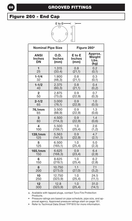
66 GROOVED FITTINGS
Nominal Pipe Size Figure 260a
ANSI Inches
DN
O.D. Inches (mm)
E to E Inches (mm)
Approx. Weight
Lbs. (kg)
1 25
1.315 (33.4)
0.8 (21,1)
0.2 (0,1)
1-1/4 32
1.900(48,3)
0.8 (21,1)
0.3 (0,1)
1-1/2 40
2.375(60,3)
0.8 (21,1)
0.4 (0,2)
2 50
2.875(73,0)
0.9 (22,9)
0.7 (0,3)
2-1/2 65
3.000 (76,1)
0.9 (22,9)
1.0 (0,5)
76,1mm 65
3.500(88,9)
0.9 (22,9)
1.3 (0,6)
3 80
4.500(114,3)
0.9 (22,9)
1.4 (0,6)
4 100
5.500 (139,7)
1.0 (25,4)
2.6 (1,2)
139,1mm 125
5.563(141,3)
0.9 (22,9)
4.7 (2,1)
5 125
6.500 (165,1)
1.0 (25,4)
5.0 (2,3)
165,1mm 150
6.625(168,3)
0.9 (23,4)
6.4 (2,9)
6 150
8.625(219,1)
1.0 (25,4)
6.2 (2,8)
8 200
10.750(273,0)
1.1 (27,0)
7.1 (3,2)
10 250
12.750(323,9)
1.0 (25,4)
24.5 (11,1)
12 300
12.8(323,9)
1.0 (25,4)
31.0 (14,1)
a. Available with tapped plugs, contact Tyco Fire Protection Products.
• Pressure ratings are based on pipe schedule, pipe size, and ap-proval agency. Approved pressure ratings start on page 161.
• Refer to Technical Data Sheet TFP1815 for more information.
Figure 260 - End CapE to E
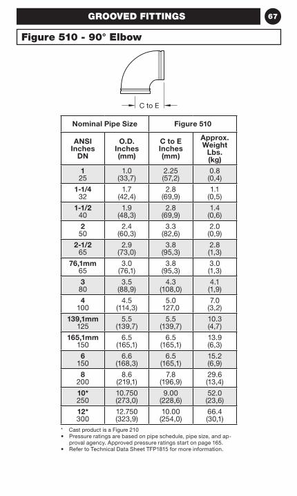
67GROOVED FITTINGS
Nominal Pipe Size Figure 510
ANSI Inches
DN
O.D. Inches (mm)
C to E Inches (mm)
Approx. Weight
Lbs. (kg)
1 25
1.0 (33,7)
2.25 (57,2)
0.8 (0,4)
1-1/4 32
1.7(42,4)
2.8(69,9)
1.1(0,5)
1-1/2 40
1.9(48,3)
2.8(69,9)
1.4(0,6)
2 50
2.4(60,3)
3.3(82,6)
2.0(0,9)
2-1/2 65
2.9(73,0)
3.8(95,3)
2.8(1,3)
76,1mm 65
3.0 (76,1)
3.8(95,3)
3.0(1,3)
3 80
3.5(88,9)
4.3(108,0)
4.1(1,9)
4 100
4.5(114,3)
5.0127,0
7.0(3,2)
139,1mm 125
5.5(139,7)
5.5 (139,7)
10.3 (4,7)
165,1mm 150
6.5 (165,1)
6.5 (165,1)
13.9 (6,3)
6 150
6.6 (168,3)
6.5 (165,1)
15.2 (6,9)
8 200
8.6 (219,1)
7.8 (196,9)
29.6 (13,4)
10* 250
10.750(273,0)
9.00 (228,6)
52.0 (23,6)
12* 300
12.750(323,9)
10.00 (254,0)
66.4 (30,1)
* Cast product is a Figure 210• Pressure ratings are based on pipe schedule, pipe size, and ap-
proval agency. Approved pressure ratings start on page 165.• Refer to Technical Data Sheet TFP1815 for more information.
Figure 510 - 90° Elbow
C to E
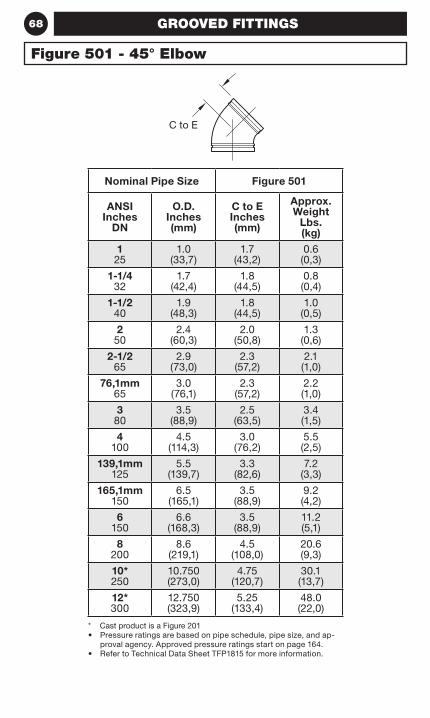
68 GROOVED FITTINGS
Nominal Pipe Size Figure 501
ANSI Inches
DN
O.D. Inches (mm)
C to E Inches (mm)
Approx. Weight
Lbs. (kg)
1 25
1.0 (33,7)
1.7 (43,2)
0.6 (0,3)
1-1/4 32
1.7(42,4)
1.8(44,5)
0.8(0,4)
1-1/2 40
1.9(48,3)
1.8(44,5)
1.0(0,5)
2 50
2.4(60,3)
2.0(50,8)
1.3(0,6)
2-1/2 65
2.9(73,0)
2.3(57,2)
2.1(1,0)
76,1mm 65
3.0(76,1)
2.3(57,2)
2.2(1,0)
3 80
3.5(88,9)
2.5(63,5)
3.4(1,5)
4 100
4.5(114,3)
3.0(76,2)
5.5(2,5)
139,1mm 125
5.5 (139,7)
3.3(82,6)
7.2(3,3)
165,1mm 150
6.5 (165,1)
3.5(88,9)
9.2(4,2)
6 150
6.6 (168,3)
3.5 (88,9)
11.2 (5,1)
8 200
8.6 (219,1)
4.5 (108,0)
20.6 (9,3)
10* 250
10.750(273,0)
4.75 (120,7)
30.1 (13,7)
12* 300
12.750(323,9)
5.25 (133,4)
48.0 (22,0)
* Cast product is a Figure 201• Pressure ratings are based on pipe schedule, pipe size, and ap-
proval agency. Approved pressure ratings start on page 164.• Refer to Technical Data Sheet TFP1815 for more information.
Figure 501 - 45° Elbow
C to E
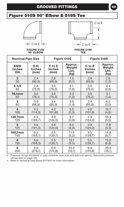
69
Figure 510S 90° Elbow & 519S Tee
GROOVED FITTINGS
FIGURE 510S 90° ELBOW
FIGURE 519S TEE
Nominal Pipe Size Figure 510S Figure 519S
ANSI Inches
DN
O.D. Inches (mm)
C to E Inches (mm)
Approx. Weight
Lbs. (kg)
C to E Inches (mm)
Approx. Weight
Lbs. (kg)
2 50
2.4(60,3)
2.8 (69,9)
1.5 (0,7)
2.8 (69,9)
2.6 (1,2)
2-1/2 65
2.9(73,0)
3.0 (76,2)
2.1 (1,0)
3.0 (76,2)
4.4 (2,0)
76,1mm 65
3.0 (76,1)
3.0 (76,2)
2.3 (1,0)
3.0 (76,2)
3.1 (1,4)
3 80
3.5(88,9)
3.4 (85,9)
3.0 (1,4)
3.4 (85,9)
6.5 (3,0)
4 100
4.5(114,3)
4.0 101,60
5.0 (2,3)
4.0 (101,6)
10.7 (4,9)
139.7mm 125
5.5 (139,7)
4.9 (124,0)
8.7 (3,9)
4.9 (124,0)
10.9 (5,0)
5 125
5.6 (141,3)
4.8 (124,0)
9.4 (4,3)
4.9 (124,0)
11.6 (5,3)
165,1mm 150
6.5 (165,1)
5.5 (139,7)
11.4 (5,2)
5.5 (139,7)
14.8 (6,7)
6 150
6.6 (168,3)
5.5 (139,7)
12.1 (5,5)
5.5 (139,7)
15.0 (6,8)
8 200
8.6 (219,1)
6.9 (174,8)
22.2 (10,1)
6.9 (174,8)
39.8 (18,1)
• Pressure ratings are based on pipe schedule, pipe size, and approval agency. Approved pressure ratings start on page 167.
• Refer to Technical Data Sheet TFP1815 for more information.
C to E C to E
C to E
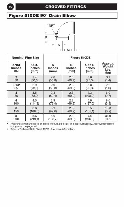
70
Figure 510DE 90° Drain Elbow
GROOVED FITTINGS
Nominal Pipe Size Figure 510DE
ANSI Inches
DN
O.D. Inches (mm)
A Inches (mm)
B Inches (mm)
C to E Inches (mm)
Approx. Weight
Lbs. (kg)
2 50
2.4(60,3)
2.0 (50,8)
2.8 (69,9)
3.8 (95,3)
3.1 (1,4)
2-1/2 65
2.9(73,0)
2.0 (50,8)
2.8 (69,9)
3.8 (95,3)
2.2 (1,0)
3 80
3.5(88,9)
2.3 (59,4)
2.8 (69,9)
4.3 (108,0)
6.0 (2,7)
4 100
4.5(114,3)
2.9 (72,4)
2.8 (69,9)
5.0 (127,0)
8.6 (3,9)
6 150
6.6 (168,3)
3.9 (99,6)
2.8 (69,9)
6.5 (165,1)
18.0 (8,2)
8 200
8.6 (219,1)
5.0 (125,7)
2.8 (69,9)
7.8 (196,9)
31.0 (14,1)
• Pressure ratings are based on pipe schedule, pipe size, and approval agency. Approved pressure ratings start on page 167.
• Refer to Technical Data Sheet TFP1815 for more information.
C to E
A
B
1" NPT
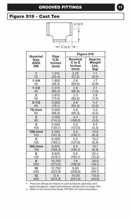
71
Figure 519 - Cast Tee
GROOVED FITTINGS
Nominal Size ANSI DN
Pipe O.D.
Inches (mm)
Figure 519
Nominal C to E Inches (mm)
Approx. Weight
Lbs. (kg)
1 25
1.315 (33.4)
2.25 (57,2)
1.1 (0,5)
1-1/4 32
1.900(48,3)
2.8(69,9)
1.7(0,8)
1-1/2 40
2.375(60,3)
2.8(69,9)
2.1(1,0)
2 50
2.875(73,0)
3.3(82,6)
2.8(1,3)
2-1/2 65
3.000 (76,1)
3.8(95,3)
4.4(2,0)
76,1mm 65
3.500(88,9)
3.8(95,3)
4.5(2,0)
3 80
4.500(114,3)
4.3(108,0)
6.5(3,0)
4 100
5.500 (139,7)
5.0(127,0)
9.5(4,3)
139,1mm 125
5.563(141,3)
5.5(139,7)
13.9(6,3)
5 125
6.500 (165,1)
5.0(127,0)
14.2(6,4)
165,1mm 150
6.625(168,3)
6.5(165,1)
19.7(8,9)
6 150
8.625(219,1)
6.5(165,1)
22.4(10,2)
8 200
10.750(273,0)
7.8(196,9)
39.8(18,1)
10 250
12.750(323,9)
9.00(228,6)
64.2(29,1)
12 300
12.8(323,9)
10.00(254,0)
110.0(49,9)
• Pressure ratings are based on pipe schedule, pipe size, and approval agency. Approved pressure ratings start on page 166.
• Refer to Technical Data Sheet TFP1815 for more information.
C to E
C to E
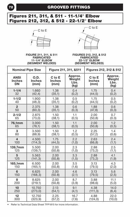
72 GROOVED FITTINGS
FIGURES 212, 312, & 512 FABRICATED
22-1/2° ELBOW (SEGMENT WELDED)
FIGURE 211, 311, & 511 FABRICATED
11-1/4° ELBOW (SEGMENT WELDED)
Nominal Pipe Size Figure 211, 311, &511 Figures 212, 312 & 512
ANSI Inches
DN
O.D. Inches (mm)
C to E Inches (mm)
Approx. Weight
Lbs. (kg)
C to E Inches (mm)
Approx. Weight
Lbs. (kg)
1-1/4 32
1.660(42,4)
1.38 (35,1)
0.4 (0,2)
1.75 (44,5)
0.4 (0,2)
1-1/2 40
1.900(48,3)
1.38 (35,1)
0.5 (0,2)
1.75 (44,5)
0.5 (0,2)
2 50
2.375(60,3)
1.38 (35,1)
0.6 (0,3)
1.88 (47,8)
0.6 (0,3)
2-1/2 65
2.875(73,0)
1.50 (38,1)
1.1 (0,5)
2.00 (50,8)
0.7 (0.3)
76,1mm 65
3.000 (76,1)
1.50 (38,1)
1.1 (0,5)
2.00 (50,8)
1.2 (0,5)
380
3.500(88,9)
1.50 (38,1)
1.2 (0,5)
2.25 (57,2)
1.4 (0,6)
4100
4.500(114,3)
1.75 (44,5)
2.2 (1,0)
2.63 (66,8)
2.4 (1,1)
139,7mm 125
5.500 (139,7)
2.00 (50,8)
2.3 (1,0)
2.88 (73,2)
2.5 (1,1)
5125
5.563(141,3)
2.00 (50,8)
3.3 (1,5)
2.88 (73,2)
4.1 (1,9)
165,1mm 150
6.500 (165,1)
2.00 (50,8)
3.5 (1,6)
3.13 (79,5)
4.3 (2,0)
6150
6.625(168,3)
2.00 (50.8)
4.6 (2,1)
3.13 (79,5)
5.6 (2,5)
8200
8.625(219,1)
2.00 (50,8)
8.7 (3,9)
3.88 (98,6)
11.1 (5,0)
10250
10.750(273,0)
2.13 (54,1)
9.1 (4,1)
4.38 (111,3)
14.0 (6,4)
12300
12.750(323,9)
2.25 (57,2)
16.7 (7,6)
4.88 (124,0)
22.0 (10,0)
• Refer to Technical Data Sheet TFP1815 for more information.
Figures 211, 311, & 511 - 11-1/4º ElbowFigures 212, 312, & 512 - 22-1/2º Elbow
C to EC to E
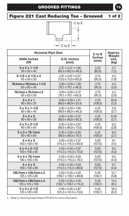
73GROOVED FITTINGS
Nominal Pipe Size C to E Inches (mm)
Approx. Weight
Lbs. (kg)
ANSI Inches DN
O.D. Inches (mm)
2 x 2 x 1-1/2 50 x 50 x 40
2.37 x 2.37 x 1.90 (60,3 x 60,3 x 48,3)
3.25 (82,6)
2.7 (1,2)
2-1/2 x 2-1/2 x 2 65 x 65 x 50
2.87 x 2.87 x 2.37 (73,0 x 73,0 x 60,3)
3.75 (95,3)
4.2 (1,9)
76,1mm x 76,1mm x 1-1/2 65 x 65 x 40
3.00 x 3.00 x 1.90 (76,1 x 76,1 x 48,3)
3.75 (95,3)
4.5 (2,0)
76,1mm x 76,1mm x 2 65 x 65 x 50
3.00 x 3.00 x 2.37 (76,1 x 76,1 x 60,3)
3.75 (95,3)
4.3 (2,0)
3 x 3 x 1 80 x 80 x 25
3.50 x 3.50 x 1.31 (88,9 x 88,9 x 33,4)
4.25 (108,0)
65.6 (2,5)
3 x 3 x 1-1/2 80 x 80 x 40
3.50 x 3.50 x 1.90 (88,9 x 88,9 x 48,3)
4.25 (108,0)
5.9 (2,7)
3 x 3 x 2 80 x 80 x 50
3.50 x 3.50 x 2.37 (88,9 x 88,9 x 60,3)
4.25 (108,0)
6.40 (2,7)
3 x 3 x 2-1/2 80 x 80 x 65
3.50 x 3.50 x 2.87 (88,9 x 88,9 x 73,0)
4.25 (108,0)
6.2 (2,8)
3 x 3 x 76,1mm 80 x 80 x 65
3.50 x 3.50 x 3.00 (88,9 x 88,9 x 76,1)
4.25 (108,0)
6.0 (2,7)
4 x 4 x 2 100 x 100 x 50
4.50 x 4.50 x 2.37 (114,3 x 114,3 x 60,3)
5.00 (127,0)
9.1 (4,1)
4 x 4 x 2-1/2 100 x 100 x 65
4.50 x 4.50 x 2.87 (114,3 x 114,3 x 73,0)
5.00 (127,0)
9.5 (4,3)
4 x 4 x 76,1mm 100 x 100 x 65
4.50 x 4.50 x 3.00 (114,3 x 114,3 x 76,1)
5.00 (127,0)
9.5 (4,3)
4 x 4 x 3 100 x 100 x 80
4.50 x 4.50 x 3.50 (114,3 x 114,3 x 88,9)
5.00 (127,0)
9.7 (4,4)
139,7mm x 139,7mm x 3 125 x 125 x 80
5.50 x 5.50 x 3.50 (139,7 x 139,7 x 88,9)
5.50 (139,7)
12.7 (5,8)
139,7mm x 139,7mm x 4 125 x 125 x 100
5.50 x 5.50 x 4.50 (139,7 x 139,7 x 114,3)
5.50 (139,7)
13.4 (6,1)
5 x 5 x 2-1/2 125 x 125 x 65
5.56 x 5.56 x 2.87 (141,3 x 141,3 x 73,0)
5.50 (139,7)
18.0 (8,2)
• Refer to Technical Data Sheet TFP1815 for more information.
Figure 221 Cast Reducing Tee - Grooved 1 of 2
C to E
C to E
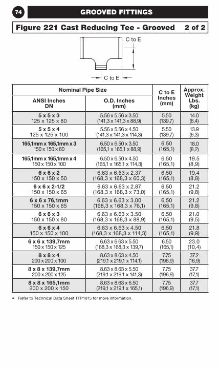
74 GROOVED FITTINGS
Nominal Pipe Size C to E Inches (mm)
Approx. Weight
Lbs. (kg)
ANSI Inches DN
O.D. Inches (mm)
5 x 5 x 3 125 x 125 x 80
5.56 x 5.56 x 3.50 (141,3 x 141,3 x 88,9)
5.50 (139,7)
14.0 (6,4)
5 x 5 x 4 125 x 125 x 100
5.56 x 5.56 x 4.50 (141,3 x 141,3 x 114,3)
5.50 (139,7)
13.9 (6,3)
165,1mm x 165,1mm x 3 150 x 150 x 80
6.50 x 6.50 x 3.50 (165,1 x 165,1 x 88,9)
6.50 (165,1)
18.0 (8,2)
165,1mm x 165,1mm x 4 150 x 150 x 100
6.50 x 6.50 x 4.50 (165,1 x 165,1 x 114,3)
6.50 (165,1)
19.5 (8,9)
6 x 6 x 2 150 x 150 x 50
6.63 x 6.63 x 2.37 (168,3 x 168,3 x 60,3)
6.50 (165,1)
19.4 (8,8)
6 x 6 x 2-1/2 150 x 150 x 65
6.63 x 6.63 x 2.87 (168,3 x 168,3 x 73,0)
6.50 (165,1)
21.2 (9,8)
6 x 6 x 76,1mm 150 x 150 x 65
6.63 x 6.63 x 3.00 (168,3 x 168,3 x 76,1)
6.50 (165,1)
21.2 (9,8)
6 x 6 x 3 150 x 150 x 80
6.63 x 6.63 x 3.50 (168,3 x 168,3 x 88,9)
6.50 (165,1)
21.0 (9,5)
6 x 6 x 4 150 x 150 x 100
6.63 x 6.63 x 4.50 (168,3 x 168,3 x 114,3)
6.50 (165,1)
21.8 (9,9)
6 x 6 x 139,7mm 150 x 150 x 125
6.63 x 6.63 x 5.50 (168,3 x 168,3 x 139,7)
6.50 (165,1)
23.0 (10,4)
8 x 8 x 4 200 x 200 x 100
8.63 x 8.63 x 4.50 (219,1 x 219,1 x 114,1)
7.75 (196,9)
37.2 (16,9)
8 x 8 x 139,7mm 200 x 200 x 125
8.63 x 8.63 x 5.50 (219,1 x 219,1 x 141,3)
7.75 (196,9)
37.7 (17,1)
8 x 8 x 165,1mm 200 x 200 x 150
8.63 x 8.63 x 6.50 (219,1 x 219,1 x 165,1)
7.75 (196,9)
37.7 (17,1)
• Refer to Technical Data Sheet TFP1815 for more information.
Figure 221 Cast Reducing Tee - Grooved 2 of 2
C to E
C to E
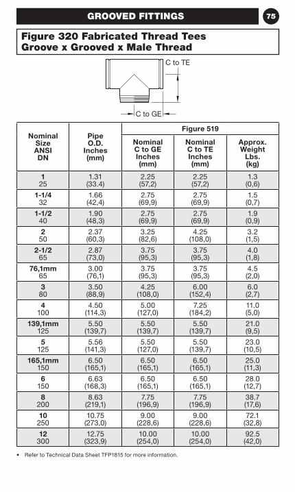
75GROOVED FITTINGS
Nominal Size ANSI DN
Pipe O.D.
Inches (mm)
Figure 519
Nominal C to GE Inches (mm)
Nominal C to TE Inches (mm)
Approx. Weight
Lbs. (kg)
1 25
1.31 (33.4)
2.25 (57,2)
2.25 (57,2)
1.3 (0,6)
1-1/4 32
1.66(42,4)
2.75(69,9)
2.75(69,9)
1.5(0,7)
1-1/2 40
1.90(48,3)
2.75(69,9)
2.75(69,9)
1.9(0,9)
2 50
2.37(60,3)
3.25(82,6)
4.25(108,0)
3.2(1,5)
2-1/2 65
2.87(73,0)
3.75(95,3)
3.75(95,3)
4.0(1,8)
76,1mm 65
3.00 (76,1)
3.75(95,3)
3.75(95,3)
4.5(2,0)
3 80
3.50(88,9)
4.25(108,0)
6.00 (152,4)
6.0(2,7)
4 100
4.50(114,3)
5.00(127,0)
7.25 (184,2)
11.0(5,0)
139,1mm 125
5.50(139,7)
5.50(139,7)
5.50(139,7)
21.0(9,5)
5 125
5.56(141,3)
5.50(127,0)
5.50(139,7)
23.0(10,5)
165,1mm 150
6.50(165,1)
6.50(165,1)
6.50(165,1)
25.0(11,3)
6 150
6.63(168,3)
6.50(165,1)
6.50(165,1)
28.0(12,7)
8 200
8.63(219,1)
7.75(196,9)
7.75(196,9)
38.7(17,6)
10 250
10.75(273,0)
9.00(228,6)
9.00(228,6)
72.1(32,8)
12 300
12.75(323,9)
10.00(254,0)
10.00(254,0)
92.5(42,0)
• Refer to Technical Data Sheet TFP1815 for more information.
Figure 320 Fabricated Thread Tees Groove x Grooved x Male Thread
C to GE
C to TE
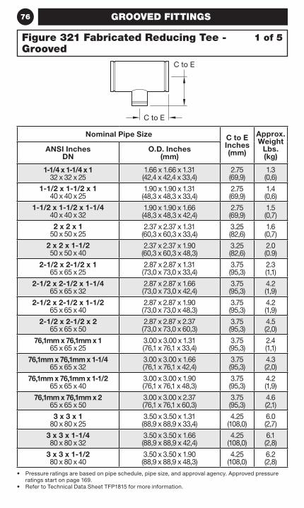
76 GROOVED FITTINGS
• Pressure ratings are based on pipe schedule, pipe size, and approval agency. Approved pressure ratings start on page 169.
• Refer to Technical Data Sheet TFP1815 for more information.
Nominal Pipe Size C to E Inches (mm)
Approx. Weight
Lbs. (kg)
ANSI Inches DN
O.D. Inches (mm)
1-1/4 x 1-1/4 x 1 32 x 32 x 25
1.66 x 1.66 x 1.31 (42,4 x 42,4 x 33,4)
2.75 (69,9)
1.3 (0,6)
1-1/2 x 1-1/2 x 1 40 x 40 x 25
1.90 x 1.90 x 1.31 (48,3 x 48,3 x 33,4)
2.75 (69,9)
1.4 (0,6)
1-1/2 x 1-1/2 x 1-1/4 40 x 40 x 32
1.90 x 1.90 x 1.66 (48,3 x 48,3 x 42,4)
2.75 (69,9)
1.5 (0,7)
2 x 2 x 1 50 x 50 x 25
2.37 x 2.37 x 1.31 (60,3 x 60,3 x 33,4)
3.25 (82,6)
1.6 (0,7)
2 x 2 x 1-1/2 50 x 50 x 40
2.37 x 2.37 x 1.90 (60,3 x 60,3 x 48,3)
3.25 (82,6)
2.0 (0.9)
2-1/2 x 2-1/2 x 1 65 x 65 x 25
2.87 x 2.87 x 1.31 (73,0 x 73,0 x 33,4)
3.75 (95,3)
2.3 (1,1)
2-1/2 x 2-1/2 x 1-1/4 65 x 65 x 32
2.87 x 2.87 x 1.66 (73,0 x 73,0 x 42,4)
3.75 (95,3)
4.2 (1,9)
2-1/2 x 2-1/2 x 1-1/2 65 x 65 x 40
2.87 x 2.87 x 1.90 (73,0 x 73,0 x 48,3)
3.75 (95,3)
4.2 (1,9)
2-1/2 x 2-1/2 x 2 65 x 65 x 50
2.87 x 2.87 x 2.37 (73,0 x 73,0 x 60,3)
3.75 (95,3)
4.5 (2,0)
76,1mm x 76,1mm x 1 65 x 65 x 25
3.00 x 3.00 x 1.31 (76,1 x 76,1 x 33,4)
3.75 (95,3)
2.4 (1,1)
76,1mm x 76,1mm x 1-1/4 65 x 65 x 32
3.00 x 3.00 x 1.66 (76,1 x 76,1 x 42,4)
3.75 (95,3)
4.3 (2,0)
76,1mm x 76,1mm x 1-1/2 65 x 65 x 40
3.00 x 3.00 x 1.90 (76,1 x 76,1 x 48,3)
3.75 (95,3)
4.2 (1,9)
76,1mm x 76,1mm x 2 65 x 65 x 50
3.00 x 3.00 x 2.37 (76,1 x 76,1 x 60,3)
3.75 (95,3)
4.6 (2,1)
3 x 3 x 1 80 x 80 x 25
3.50 x 3.50 x 1.31 (88,9 x 88,9 x 33,4)
4.25 (108,0)
6.0 (2,7)
3 x 3 x 1-1/4 80 x 80 x 32
3.50 x 3.50 x 1.66 (88,9 x 88,9 x 42,4)
4.25 (108,0)
6.1 (2,8)
3 x 3 x 1-1/2 80 x 80 x 40
3.50 x 3.50 x 1.90 (88,9 x 88,9 x 48,3)
4.25 (108,0)
6.2 (2,8)
1 of 5Figure 321 Fabricated Reducing Tee - Grooved
C to E
C to E
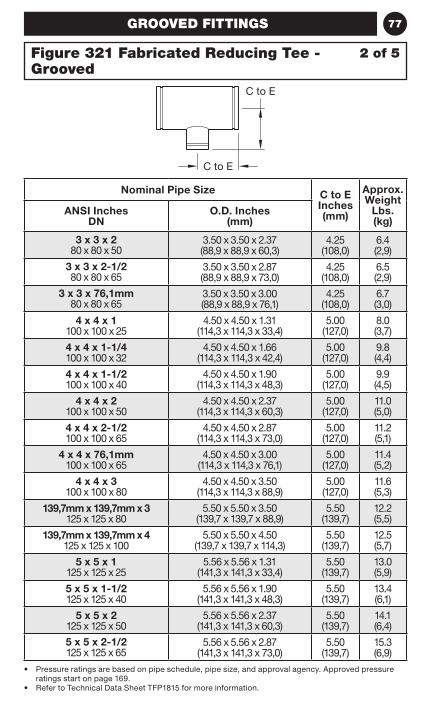
77GROOVED FITTINGS
• Pressure ratings are based on pipe schedule, pipe size, and approval agency. Approved pressure ratings start on page 169.
• Refer to Technical Data Sheet TFP1815 for more information.
Nominal Pipe Size C to E Inches (mm)
Approx. Weight
Lbs. (kg)
ANSI Inches DN
O.D. Inches (mm)
3 x 3 x 2 80 x 80 x 50
3.50 x 3.50 x 2.37 (88,9 x 88,9 x 60,3)
4.25 (108,0)
6.4 (2,9)
3 x 3 x 2-1/2 80 x 80 x 65
3.50 x 3.50 x 2.87 (88,9 x 88,9 x 73,0)
4.25 (108,0)
6.5 (2,9)
3 x 3 x 76,1mm 80 x 80 x 65
3.50 x 3.50 x 3.00 (88,9 x 88,9 x 76,1)
4.25 (108,0)
6.7 (3,0)
4 x 4 x 1 100 x 100 x 25
4.50 x 4.50 x 1.31 (114,3 x 114,3 x 33,4)
5.00 (127,0)
8.0 (3,7)
4 x 4 x 1-1/4 100 x 100 x 32
4.50 x 4.50 x 1.66 (114,3 x 114,3 x 42,4)
5.00 (127,0)
9.8 (4,4)
4 x 4 x 1-1/2 100 x 100 x 40
4.50 x 4.50 x 1.90 (114,3 x 114,3 x 48,3)
5.00 (127,0)
9.9 (4,5)
4 x 4 x 2 100 x 100 x 50
4.50 x 4.50 x 2.37 (114,3 x 114,3 x 60,3)
5.00 (127,0)
11.0 (5,0)
4 x 4 x 2-1/2 100 x 100 x 65
4.50 x 4.50 x 2.87 (114,3 x 114,3 x 73,0)
5.00 (127,0)
11.2 (5,1)
4 x 4 x 76,1mm 100 x 100 x 65
4.50 x 4.50 x 3.00 (114,3 x 114,3 x 76,1)
5.00 (127,0)
11.4 (5,2)
4 x 4 x 3 100 x 100 x 80
4.50 x 4.50 x 3.50 (114,3 x 114,3 x 88,9)
5.00 (127,0)
11.6 (5,3)
139,7mm x 139,7mm x 3 125 x 125 x 80
5.50 x 5.50 x 3.50 (139,7 x 139,7 x 88,9)
5.50 (139,7)
12.2 (5,5)
139,7mm x 139,7mm x 4 125 x 125 x 100
5.50 x 5.50 x 4.50 (139,7 x 139,7 x 114,3)
5.50 (139,7)
12.5 (5,7)
5 x 5 x 1 125 x 125 x 25
5.56 x 5.56 x 1.31 (141,3 x 141,3 x 33,4)
5.50 (139,7)
13.0 (5,9)
5 x 5 x 1-1/2 125 x 125 x 40
5.56 x 5.56 x 1.90 (141,3 x 141,3 x 48,3)
5.50 (139,7)
13.4 (6,1)
5 x 5 x 2 125 x 125 x 50
5.56 x 5.56 x 2.37 (141,3 x 141,3 x 60,3)
5.50 (139,7)
14.1 (6,4)
5 x 5 x 2-1/2 125 x 125 x 65
5.56 x 5.56 x 2.87 (141,3 x 141,3 x 73,0)
5.50 (139,7)
15.3 (6,9)
2 of 5Figure 321 Fabricated Reducing Tee - Grooved
C to E
C to E
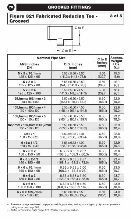
78 GROOVED FITTINGS
• Pressure ratings are based on pipe schedule, pipe size, and approval agency. Approved pressure ratings start on page 169.
• Refer to Technical Data Sheet TFP1815 for more information.
Nominal Pipe Size C to E Inches (mm)
Approx. Weight
Lbs. (kg)
ANSI Inches DN
O.D. Inches (mm)
5 x 5 x 76,1mm 125 x 125 x 65
5.56 x 5.56 x 3.00 (141,3 x 141,3 x 76,1)
5.50 (139,7)
15.3 (6,9)
5 x 5 x 3 125 x 125 x 80
5.56 x 5.56 x 3.50 (141,3 x 141,3 x 88,9)
5.50 (139,7)
16.0 (7,3)
5 x 5 x 4 125 x 125 x 100
5.56 x 5.56 x 4.50 (141,3 x 141,3 x 114,3)
5.50 (139,7)
16.4 (7,4)
165,1mm x 165,1mm x 3 150 x 150 x 80
6.50 x 6.50 x 3.50 (165,1 x 165,1 x 88,9)
6.50 (165,1)
22.0 (10,0)
165,1mm x 165,1mm x 4 150 x 150 x 100
6.50 x 6.50 x 4.50 (165,1 x 165,1 x 114,3)
6.50 (165,1)
22.6 (10,3)
165,1mm x 165,1mm x 5 150 x 150 x 125
6.50 x 6.50 x 5.56 (165,1 x 165,1 x 139,7)
6.50 (165,1)
23.2 (10,5)
165,1mm x 165,1mm x 139,7mm 150 x 150 x 125
6.50 x 6.50 x 5.50 (165,1 x 165,1 x 141,3)
6.50 (165,1)
22.9 (10,4)
6 x 6 x 1 150 x 150 x 25
6.63 x 6.63 x 1.31 (168,3 x 168,3 x 33,4)
6.50 (165,1)
22.8 (10,3)
6 x 6 x 1-1/2 150 x 150 x 40
6.63 x 6.63 x 1.90 (168,3 x 168,3 x 48,3)
6.50 (165,1)
22.9 (10,4)
6 x 6 x 2 150 x 150 x 50
6.63 x 6.63 x 2.37 (168,3 x 168,3 x 60,3)
6.50 (165,1)
23.0 (10,4)
6 x 6 x 2-1/2 150 x 150 x 65
6.63 x 6.63 x 2.87 (168,3 x 168,3 x 73,0)
6.50 (165,1)
23.4 (10,6)
6 x 6 x 76,1mm 150 x 150 x 65
6.63 x 6.63 x 3.00 (168,3 x 168,3 x 76,1)
6.50 (165,1)
23.5 (10,7)
6 x 6 x 3 150 x 150 x 80
6.63 x 6.63 x 3.50 (168,3 x 168,3 x 88,9)
6.50 (165,1)
23.7 (10,7)
6 x 6 x 4 150 x 150 x 100
6.63 x 6.63 x 4.50 (168,3 x 168,3 x 114,3)
6.50 (165,1)
23.9 (10,8)
6 x 6 x 139,7mm 150 x 150 x 125
6.63 x 6.63 x 5.50 (168,3 x 168,3 x 139,7)
6.50 (165,1)
24.0 (10,9)
3 of 5Figure 321 Fabricated Reducing Tee - Grooved
C to E
C to E
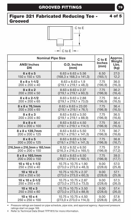
79GROOVED FITTINGS
• Pressure ratings are based on pipe schedule, pipe size, and approval agency. Approved pressure ratings start on page 169.
• Refer to Technical Data Sheet TFP1815 for more information.
Nominal Pipe Size C to E Inches (mm)
Approx. Weight
Lbs. (kg)
ANSI Inches DN
O.D. Inches (mm)
6 x 6 x 5 150 x 150 x 125
6.63 x 6.63 x 5.56 (168,3 x 168,3 x 141,3)
6.50 (165,1)
27.0 12,2
8 x 8 x 1-1/2 200 x 200 x 40
8.63 x 8.63 x 1.9 (219,1 x 219,1 x 48,3)
7.75 (196,9)
36.0 (16,3)
8 x 8 x 2 200 x 200 x 50
8.63 x 8.63 x 2.37 (219,1 x 219,1 x 60,3)
7.75 (196,9)
36.2 (16,4)
8 x 8 x 2-1/2 200 x 200 x 65
8.63 x 8.63 x 2.88 (219,1 x 219,1 x 73,0)
7.75 (196,9)
36.4 (16,5)
8 x 8 x 76,1mm 200 x 200 x 65
8.63 x 8.63 x 23.00 (219,1 x 219,1 x 76,1)
7.75 (196,9)
36.4 (16,5)
8 x 8 x 3 200 x 200 x 80
8.63 x 8.63 x 3.50 (219,1 x 219,1 x 88,9)
7.75 (196,9)
36.5 (16,6)
8 x 8 x 4 200 x 200 x 100
8.63 x 8.63 x 4.50 (219,1 x 219,1 x 114,1)
7.75 (196,9)
36.4 (16,5)
8 x 8 x 139,7mm 200 x 200 x 125
8.63 x 8.63 x 5.50 (219,1 x 219,1 x 141,3)
7.75 (196,9)
36.7 (16,6)
8 x 8 x 5 200 x 200 x 125
8.63 x 8.63 x 5.56 (219,1 x 219,1 x 141,3)
7.75 (196,9)
36.8 (16,7)
216,3mm x 216,3mm x 165,1mm 200 x 200 x 150
8.52 x 8.52 x 6.50 (216,3 x 216,3 x 165,1)
7.75 (196,9)
37.9 (17,2)
8 x 8 x 165,1mm 200 x 200 x 150
8.63 x 8.63 x 6.50 (219,1 x 219,1 x 165,1)
7.75 (196,9)
39.0 (17,7)
10 x 10 x 1-1/2 250 x 250 x 40
10.75 x 10.75 x 1.90 (273,0 x 273,0 x 48,3)
9.00 (228,6)
57.0 (25,8)
10 x 10 x 2 250 x 250 x 50
10.75 x 10.75 x 2.37 (273,0 x 273,0 x 60,3)
9.00 (228,6)
57.1 (25,9)
10 x 10 x 2-1/2 250 x 250 x 65
10.75 x 10.75 x 2.87 (273,0 x 273,0 x 73,0)
9.00 (228,6)
57.3 (26,0)
10 x 10 x 3 250 x 250 x 80
10.75 x 10.75 x 3.50 (273,0 x 273,0 x 88,9)
9.00 (228,6)
57.4 (26,0)
10 x 10 x 4 250 x 250 x 100
10.75 x 10.75 x 4.50 (273,0 x 273,0 x 114,3)
9.00 (228,6)
57.8 (26,2)
4 of 5Figure 321 Fabricated Reducing Tee - Grooved
C to E
C to E
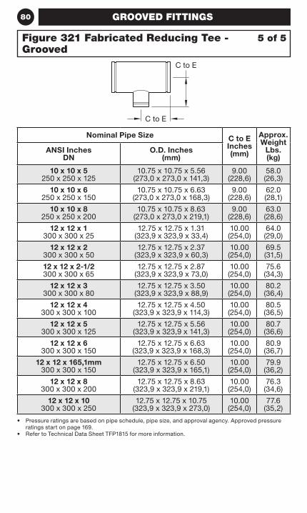
80 GROOVED FITTINGS
• Pressure ratings are based on pipe schedule, pipe size, and approval agency. Approved pressure ratings start on page 169.
• Refer to Technical Data Sheet TFP1815 for more information.
Nominal Pipe Size C to E Inches (mm)
Approx. Weight
Lbs. (kg)
ANSI Inches DN
O.D. Inches (mm)
10 x 10 x 5 250 x 250 x 125
10.75 x 10.75 x 5.56 (273,0 x 273,0 x 141,3)
9.00 (228,6)
58.0 (26,3)
10 x 10 x 6 250 x 250 x 150
10.75 x 10.75 x 6.63 (273,0 x 273,0 x 168,3)
9.00 (228,6)
62.0 (28,1)
10 x 10 x 8 250 x 250 x 200
10.75 x 10.75 x 8.63 (273,0 x 273,0 x 219,1)
9.00 (228,6)
63.0 (28,6)
12 x 12 x 1 300 x 300 x 25
12.75 x 12.75 x 1.31 (323,9 x 323,9 x 33,4)
10.00 (254,0)
64.0 (29,0)
12 x 12 x 2 300 x 300 x 50
12.75 x 12.75 x 2.37 (323,9 x 323,9 x 60,3)
10.00 (254,0)
69.5 (31,5)
12 x 12 x 2-1/2 300 x 300 x 65
12.75 x 12.75 x 2.87 (323,9 x 323,9 x 73,0)
10.00 (254,0)
75.6 (34,3)
12 x 12 x 3 300 x 300 x 80
12.75 x 12.75 x 3.50 (323,9 x 323,9 x 88,9)
10.00 (254,0)
80.2 (36,4)
12 x 12 x 4 300 x 300 x 100
12.75 x 12.75 x 4.50 (323,9 x 323,9 x 114,3)
10.00 (254,0)
80.5 (36,5)
12 x 12 x 5 300 x 300 x 125
12.75 x 12.75 x 5.56 (323,9 x 323,9 x 141,3)
10.00 (254,0)
80.7 (36,6)
12 x 12 x 6 300 x 300 x 150
12.75 x 12.75 x 6.63 (323,9 x 323,9 x 168,3)
10.00 (254,0)
80.9 (36,7)
12 x 12 x 165,1mm 300 x 300 x 150
12.75 x 12.75 x 6.50 (323,9 x 323,9 x 165,1)
10.00 (254,0)
79.9 (36,2)
12 x 12 x 8 300 x 300 x 200
12.75 x 12.75 x 8.63 (323,9 x 323,9 x 219,1)
10.00 (254,0)
76.3 (34,6)
12 x 12 x 10 300 x 300 x 250
12.75 x 12.75 x 10.75 (323,9 x 323,9 x 273,0)
10.00 (254,0)
77.6 (35,2)
5 of 5Figure 321 Fabricated Reducing Tee - Grooved
C to E
C to E
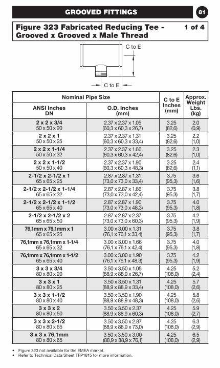
81GROOVED FITTINGS
• Figure 323 not available for the EMEA market.• Refer to Technical Data Sheet TFP1815 for more information.
Nominal Pipe Size C to E Inches (mm)
Approx. Weight
Lbs. (kg)
ANSI Inches DN
O.D. Inches (mm)
2 x 2 x 3/4 50 x 50 x 20
2.37 x 2.37 x 1.05 (60,3 x 60,3 x 26,7)
3.25 (82,6)
2.0 (0,9)
2 x 2 x 1 50 x 50 x 25
2.37 x 2.37 x 1.31 (60,3 x 60,3 x 33,4)
3.25 (82,6)
2.2 (1,0)
2 x 2 x 1-1/4 50 x 50 x 32
2.37 x 2.37 x 1.66 (60,3 x 60,3 x 42,4)
3.25 (82,6)
2.3 (1,0)
2 x 2 x 1-1/2 50 x 50 x 40
2.37 x 2.37 x 1.90 (60,3 x 60,3 x 48,3)
3.25 (82,6)
2.4 (1,1)
2-1/2 x 2-1/2 x 1 65 x 65 x 25
2.87 x 2.87 x 1.31 (73,0 x 73,0 x 33,4)
3.75 (95,3)
3.6 (1,6)
2-1/2 x 2-1/2 x 1-1/4 65 x 65 x 32
2.87 x 2.87 x 1.66 (73,0 x 73,0 x 42,4)
3.75 (95,3)
3.8 (1,7)
2-1/2 x 2-1/2 x 1-1/2 65 x 65 x 40
2.87 x 2.87 x 1.90 (73,0 x 73,0 x 48,3)
3.75 (95,3)
4.0 (1,8)
2-1/2 x 2-1/2 x 2 65 x 65 x 50
2.87 x 2.87 x 2.37 (73,0 x 73,0 x 60,3)
3.75 (95,3)
4.2 (1,9)
76,1mm x 76,1mm x 1 65 x 65 x 25
3.00 x 3.00 x 1.31 (76,1 x 76,1 x 33,4)
3.75 (95,3)
3.8 (1,7)
76,1mm x 76,1mm x 1-1/4 65 x 65 x 32
3.00 x 3.00 x 1.66 (76,1 x 76,1 x 42,4)
3.75 (95,3)
4.0 (1,8)
76,1mm x 76,1mm x 1-1/2 65 x 65 x 40
3.00 x 3.00 x 1.90 (76,1 x 76,1 x 48,3)
3.75 (95,3)
4.2 (1,9)
3 x 3 x 3/4 80 x 80 x 20
3.50 x 3.50 x 1.05 (88,9 x 88,9 x 26,7)
4.25 (108,0)
5.2 (2,4)
3 x 3 x 1 80 x 80 x 25
3.50 x 3.50 x 1.31 (88,9 x 88,9 x 33,4)
4.25 (108,0)
5.7 (2,6)
3 x 3 x 1-1/2 80 x 80 x 40
3.50 x 3.50 x 1.90 (88,9 x 88,9 x 48,3)
4.25 (108,0)
5.8 (2,6)
3 x 3 x 2 80 x 80 x 50
3.50 x 3.50 x 2.37 (88,9 x 88,9 x 60,3)
4.25 (108,0)
5.9 (2,7)
3 x 3 x 2-1/2 80 x 80 x 65
3.50 x 3.50 x 2.87 (88,9 x 88,9 x 73,0)
4.25 (108,0)
6.3 (2,9)
3 x 3 x 76,1mm 80 x 80 x 65
3.50 x 3.50 x 3.00 (88,9 x 88,9 x 76,1)
4.25 (108,0)
6.5 (2,9)
1 of 4Figure 323 Fabricated Reducing Tee - Grooved x Grooved x Male Thread
C to E
C to E
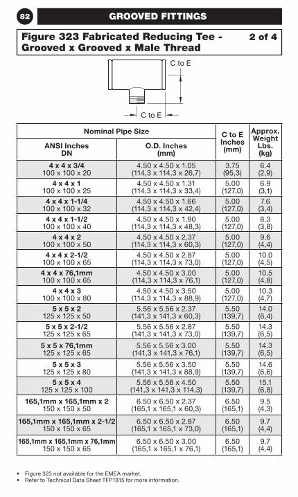
82 GROOVED FITTINGS
• Figure 323 not available for the EMEA market.• Refer to Technical Data Sheet TFP1815 for more information.
Nominal Pipe Size C to E Inches (mm)
Approx. Weight
Lbs. (kg)
ANSI Inches DN
O.D. Inches (mm)
4 x 4 x 3/4 100 x 100 x 20
4.50 x 4.50 x 1.05 (114,3 x 114,3 x 26,7)
3.75 (95,3)
6.4 (2,9)
4 x 4 x 1 100 x 100 x 25
4.50 x 4.50 x 1.31 (114,3 x 114,3 x 33,4)
5.00 (127,0)
6.9 (3,1)
4 x 4 x 1-1/4 100 x 100 x 32
4.50 x 4.50 x 1.66 (114,3 x 114,3 x 42,4)
5.00 (127,0)
7.6 (3,4)
4 x 4 x 1-1/2 100 x 100 x 40
4.50 x 4.50 x 1.90 (114,3 x 114,3 x 48,3)
5.00 (127,0)
8.3 (3,8)
4 x 4 x 2 100 x 100 x 50
4.50 x 4.50 x 2.37 (114,3 x 114,3 x 60,3)
5.00 (127,0)
9.6 (4,4)
4 x 4 x 2-1/2 100 x 100 x 65
4.50 x 4.50 x 2.87 (114,3 x 114,3 x 73,0)
5.00 (127,0)
10.0 (4,5)
4 x 4 x 76,1mm 100 x 100 x 65
4.50 x 4.50 x 3.00 (114,3 x 114,3 x 76,1)
5.00 (127,0)
10.5 (4,8)
4 x 4 x 3 100 x 100 x 80
4.50 x 4.50 x 3.50 (114,3 x 114,3 x 88,9)
5.00 (127,0)
10.3 (4,7)
5 x 5 x 2 125 x 125 x 50
5.56 x 5.56 x 2.37 (141,3 x 141,3 x 60,3)
5.50 (139,7)
14.0 (6,4)
5 x 5 x 2-1/2 125 x 125 x 65
5.56 x 5.56 x 2.87 (141,3 x 141,3 x 73,0)
5.50 (139,7)
14.3 (6,5)
5 x 5 x 76,1mm 125 x 125 x 65
5.56 x 5.56 x 3.00 (141,3 x 141,3 x 76,1)
5.50 (139,7)
14.3 (6,5)
5 x 5 x 3 125 x 125 x 80
5.56 x 5.56 x 3.50 (141,3 x 141,3 x 88,9)
5.50 (139,7)
14.6 (6,6)
5 x 5 x 4 125 x 125 x 100
5.56 x 5.56 x 4.50 (141,3 x 141,3 x 114,3)
5.50 (139,7)
15.1 (6,8)
165,1mm x 165,1mm x 2 150 x 150 x 50
6.50 x 6.50 x 2.37 (165,1 x 165,1 x 60,3)
6.50 (165,1)
9.5 (4,3)
165,1mm x 165,1mm x 2-1/2 150 x 150 x 65
6.50 x 6.50 x 2.87 (165,1 x 165,1 x 73,0)
6.50 (165,1)
9.7 (4,4)
165,1mm x 165,1mm x 76,1mm 150 x 150 x 65
6.50 x 6.50 x 3.00 (165,1 x 165,1 x 76,1)
6.50 (165,1)
9.7 (4,4)
2 of 4Figure 323 Fabricated Reducing Tee - Grooved x Grooved x Male Thread
C to E
C to E
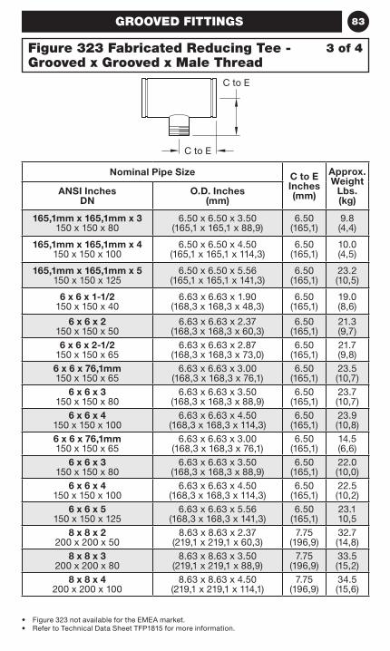
83GROOVED FITTINGS
• Figure 323 not available for the EMEA market.• Refer to Technical Data Sheet TFP1815 for more information.
Nominal Pipe Size C to E Inches (mm)
Approx. Weight
Lbs. (kg)
ANSI Inches DN
O.D. Inches (mm)
165,1mm x 165,1mm x 3 150 x 150 x 80
6.50 x 6.50 x 3.50 (165,1 x 165,1 x 88,9)
6.50 (165,1)
9.8 (4,4)
165,1mm x 165,1mm x 4 150 x 150 x 100
6.50 x 6.50 x 4.50 (165,1 x 165,1 x 114,3)
6.50 (165,1)
10.0 (4,5)
165,1mm x 165,1mm x 5 150 x 150 x 125
6.50 x 6.50 x 5.56 (165,1 x 165,1 x 141,3)
6.50 (165,1)
23.2 (10,5)
6 x 6 x 1-1/2 150 x 150 x 40
6.63 x 6.63 x 1.90 (168,3 x 168,3 x 48,3)
6.50 (165,1)
19.0 (8,6)
6 x 6 x 2 150 x 150 x 50
6.63 x 6.63 x 2.37 (168,3 x 168,3 x 60,3)
6.50 (165,1)
21.3 (9,7)
6 x 6 x 2-1/2 150 x 150 x 65
6.63 x 6.63 x 2.87 (168,3 x 168,3 x 73,0)
6.50 (165,1)
21.7 (9,8)
6 x 6 x 76,1mm 150 x 150 x 65
6.63 x 6.63 x 3.00 (168,3 x 168,3 x 76,1)
6.50 (165,1)
23.5 (10,7)
6 x 6 x 3 150 x 150 x 80
6.63 x 6.63 x 3.50 (168,3 x 168,3 x 88,9)
6.50 (165,1)
23.7 (10,7)
6 x 6 x 4 150 x 150 x 100
6.63 x 6.63 x 4.50 (168,3 x 168,3 x 114,3)
6.50 (165,1)
23.9 (10,8)
6 x 6 x 76,1mm 150 x 150 x 65
6.63 x 6.63 x 3.00 (168,3 x 168,3 x 76,1)
6.50 (165,1)
14.5 (6,6)
6 x 6 x 3 150 x 150 x 80
6.63 x 6.63 x 3.50 (168,3 x 168,3 x 88,9)
6.50 (165,1)
22.0 (10,0)
6 x 6 x 4 150 x 150 x 100
6.63 x 6.63 x 4.50 (168,3 x 168,3 x 114,3)
6.50 (165,1)
22.5 (10,2)
6 x 6 x 5 150 x 150 x 125
6.63 x 6.63 x 5.56 (168,3 x 168,3 x 141,3)
6.50 (165,1)
23.1 10,5
8 x 8 x 2 200 x 200 x 50
8.63 x 8.63 x 2.37 (219,1 x 219,1 x 60,3)
7.75 (196,9)
32.7 (14,8)
8 x 8 x 3 200 x 200 x 80
8.63 x 8.63 x 3.50 (219,1 x 219,1 x 88,9)
7.75 (196,9)
33.5 (15,2)
8 x 8 x 4 200 x 200 x 100
8.63 x 8.63 x 4.50 (219,1 x 219,1 x 114,1)
7.75 (196,9)
34.5 (15,6)
3 of 4Figure 323 Fabricated Reducing Tee - Grooved x Grooved x Male Thread
C to E
C to E
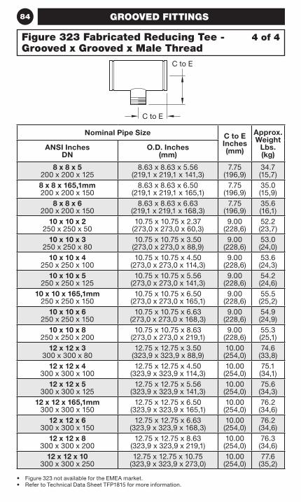
84 GROOVED FITTINGS
• Figure 323 not available for the EMEA market.• Refer to Technical Data Sheet TFP1815 for more information.
Nominal Pipe Size C to E Inches (mm)
Approx. Weight
Lbs. (kg)
ANSI Inches DN
O.D. Inches (mm)
8 x 8 x 5 200 x 200 x 125
8.63 x 8.63 x 5.56 (219,1 x 219,1 x 141,3)
7.75 (196,9)
34.7 (15,7)
8 x 8 x 165,1mm 200 x 200 x 150
8.63 x 8.63 x 6.50 (219,1 x 219,1 x 165,1)
7.75 (196,9)
35.0 (15,9)
8 x 8 x 6 200 x 200 x 150
8.63 x 8.63 x 6.63 (219,1 x 219,1 x 168,3)
7.75 (196,9)
35.6 (16,1)
10 x 10 x 2 250 x 250 x 50
10.75 x 10.75 x 2.37 (273,0 x 273,0 x 60,3)
9.00 (228,6)
52.2 (23,7)
10 x 10 x 3 250 x 250 x 80
10.75 x 10.75 x 3.50 (273,0 x 273,0 x 88,9)
9.00 (228,6)
53.0 (24,0)
10 x 10 x 4 250 x 250 x 100
10.75 x 10.75 x 4.50 (273,0 x 273,0 x 114,3)
9.00 (228,6)
53.6 (24,3)
10 x 10 x 5 250 x 250 x 125
10.75 x 10.75 x 5.56 (273,0 x 273,0 x 141,3)
9.00 (228,6)
54.2 (24,6)
10 x 10 x 165,1mm 250 x 250 x 150
10.75 x 10.75 x 6.50 (273,0 x 273,0 x 165,1)
9.00 (228,6)
55.5 (25,2)
10 x 10 x 6 250 x 250 x 150
10.75 x 10.75 x 6.63 (273,0 x 273,0 x 168,3)
9.00 (228,6)
54.9 (24,9)
10 x 10 x 8 250 x 250 x 200
10.75 x 10.75 x 8.63 (273,0 x 273,0 x 219,1)
9.00 (228,6)
55.3 (25,1)
12 x 12 x 3 300 x 300 x 80
12.75 x 12.75 x 3.50 (323,9 x 323,9 x 88,9)
10.00 (254,0)
74.6 (33,8)
12 x 12 x 4 300 x 300 x 100
12.75 x 12.75 x 4.50 (323,9 x 323,9 x 114,3)
10.00 (254,0)
75.1 (34,1)
12 x 12 x 5 300 x 300 x 125
12.75 x 12.75 x 5.56 (323,9 x 323,9 x 141,3)
10.00 (254,0)
75.6 (34,3)
12 x 12 x 165,1mm 300 x 300 x 150
12.75 x 12.75 x 6.50 (323,9 x 323,9 x 165,1)
10.00 (254,0)
76.2 (34,6)
12 x 12 x 6 300 x 300 x 150
12.75 x 12.75 x 6.63 (323,9 x 323,9 x 168,3)
10.00 (254,0)
76.2 (34,6)
12 x 12 x 8 300 x 300 x 200
12.75 x 12.75 x 8.63 (323,9 x 323,9 x 219,1)
10.00 (254,0)
76.3 (34,6)
12 x 12 x 10 300 x 300 x 250
12.75 x 12.75 x 10.75 (323,9 x 323,9 x 273,0)
10.00 (254,0)
77.6 (35,2)
4 of 4Figure 323 Fabricated Reducing Tee - Grooved x Grooved x Male Thread
C to E
C to E
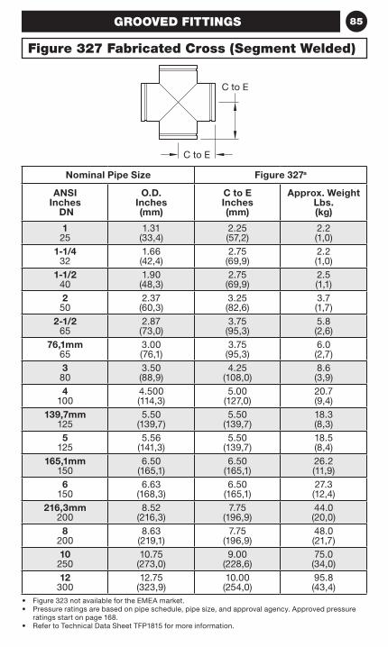
85
Figure 327 Fabricated Cross (Segment Welded)
GROOVED FITTINGS
Nominal Pipe Size Figure 327a
ANSI Inches
DN
O.D. Inches (mm)
C to E Inches (mm)
Approx. Weight Lbs. (kg)
1 25
1.31 (33,4)
2.25 (57,2)
2.2 (1,0)
1-1/4 32
1.66 (42,4)
2.75 (69,9)
2.2 (1,0)
1-1/2 40
1.90 (48,3)
2.75 (69,9)
2.5 (1,1)
2 50
2.37 (60,3)
3.25 (82,6)
3.7 (1,7)
2-1/2 65
2.87 (73,0)
3.75 (95,3)
5.8 (2,6)
76,1mm 65
3.00 (76,1)
3.75 (95,3)
6.0 (2,7)
3 80
3.50 (88,9)
4.25 (108,0)
8.6 (3,9)
4 100
4.500 (114,3)
5.00 (127,0)
20.7 (9,4)
139,7mm 125
5.50 (139,7)
5.50 (139,7)
18.3 (8,3)
5 125
5.56 (141,3)
5.50 (139,7)
18.5 (8,4)
165,1mm 150
6.50 (165,1)
6.50 (165,1)
26.2 (11,9)
6 150
6.63 (168,3)
6.50 (165,1)
27.3 (12,4)
216,3mm 200
8.52 (216,3)
7.75 (196,9)
44.0 (20,0)
8 200
8.63 (219,1)
7.75 (196,9)
48.0 (21,7)
10 250
10.75 (273,0)
9.00 (228,6)
75.0 (34,0)
12 300
12.75 (323,9)
10.00 (254,0)
95.8 (43,4)
• Figure 323 not available for the EMEA market.• Pressure ratings are based on pipe schedule, pipe size, and approval agency. Approved pressure
ratings start on page 168.• Refer to Technical Data Sheet TFP1815 for more information.
C to E
C to E
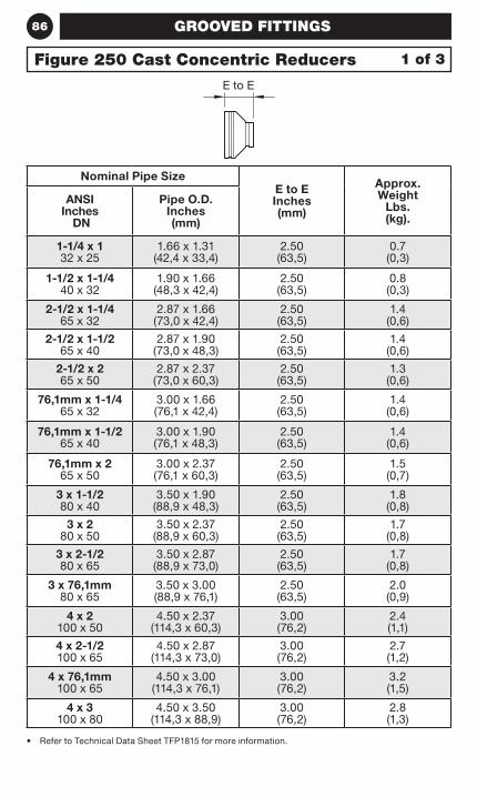
86 GROOVED FITTINGS
• Refer to Technical Data Sheet TFP1815 for more information.
Nominal Pipe SizeE to E Inches (mm)
Approx. Weight
Lbs. (kg).
ANSI Inches
DN
Pipe O.D. Inches (mm)
1-1/4 x 1 32 x 25
1.66 x 1.31 (42,4 x 33,4)
2.50 (63,5)
0.7 (0,3)
1-1/2 x 1-1/4 40 x 32
1.90 x 1.66 (48,3 x 42,4)
2.50 (63,5)
0.8 (0,3)
2-1/2 x 1-1/4 65 x 32
2.87 x 1.66 (73,0 x 42,4)
2.50 (63,5)
1.4 (0,6)
2-1/2 x 1-1/2 65 x 40
2.87 x 1.90 (73,0 x 48,3)
2.50 (63,5)
1.4 (0,6)
2-1/2 x 2 65 x 50
2.87 x 2.37 (73,0 x 60,3)
2.50 (63,5)
1.3 (0,6)
76,1mm x 1-1/4 65 x 32
3.00 x 1.66 (76,1 x 42,4)
2.50 (63,5)
1.4 (0,6)
76,1mm x 1-1/2 65 x 40
3.00 x 1.90 (76,1 x 48,3)
2.50 (63,5)
1.4 (0,6)
76,1mm x 2 65 x 50
3.00 x 2.37 (76,1 x 60,3)
2.50 (63,5)
1.5 (0,7)
3 x 1-1/2 80 x 40
3.50 x 1.90 (88,9 x 48,3)
2.50 (63,5)
1.8 (0,8)
3 x 2 80 x 50
3.50 x 2.37 (88,9 x 60,3)
2.50 (63,5)
1.7 (0,8)
3 x 2-1/2 80 x 65
3.50 x 2.87 (88,9 x 73,0)
2.50 (63,5)
1.7 (0,8)
3 x 76,1mm 80 x 65
3.50 x 3.00 (88,9 x 76,1)
2.50 (63,5)
2.0 (0,9)
4 x 2 100 x 50
4.50 x 2.37 (114,3 x 60,3)
3.00 (76,2)
2.4 (1,1)
4 x 2-1/2 100 x 65
4.50 x 2.87 (114,3 x 73,0)
3.00 (76,2)
2.7 (1,2)
4 x 76,1mm 100 x 65
4.50 x 3.00 (114,3 x 76,1)
3.00 (76,2)
3.2 (1,5)
4 x 3 100 x 80
4.50 x 3.50 (114,3 x 88,9)
3.00 (76,2)
2.8 (1,3)
1 of 3Figure 250 Cast Concentric Reducers
E to E
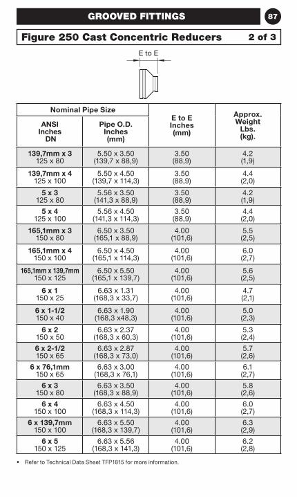
87GROOVED FITTINGS
• Refer to Technical Data Sheet TFP1815 for more information.
Nominal Pipe SizeE to E Inches (mm)
Approx. Weight
Lbs. (kg).
ANSI Inches
DN
Pipe O.D. Inches (mm)
139,7mm x 3 125 x 80
5.50 x 3.50 (139,7 x 88,9)
3.50 (88,9)
4.2 (1,9)
139,7mm x 4 125 x 100
5.50 x 4.50 (139,7 x 114,3)
3.50 (88,9)
4.4 (2,0)
5 x 3 125 x 80
5.56 x 3.50 (141,3 x 88,9)
3.50 (88,9)
4.2 (1,9)
5 x 4 125 x 100
5.56 x 4.50 (141,3 x 114,3)
3.50 (88,9)
4.4 (2,0)
165,1mm x 3 150 x 80
6.50 x 3.50 (165,1 x 88,9)
4.00 (101,6)
5.5 (2,5)
165,1mm x 4 150 x 100
6.50 x 4.50 (165,1 x 114,3)
4.00 (101,6)
6.0 (2,7)
165,1mm x 139,7mm 150 x 125
6.50 x 5.50 (165,1 x 139,7)
4.00 (101,6)
5.6 (2,5)
6 x 1 150 x 25
6.63 x 1.31 (168,3 x 33,7)
4.00 (101,6)
4.7 (2,1)
6 x 1-1/2 150 x 40
6.63 x 1.90 (168,3 x48,3)
4.00 (101,6)
5.0 (2,3)
6 x 2 150 x 50
6.63 x 2.37 (168,3 x 60,3)
4.00 (101,6)
5.3 (2,4)
6 x 2-1/2 150 x 65
6.63 x 2.87 (168,3 x 73,0)
4.00 (101,6)
5.7 (2,6)
6 x 76,1mm 150 x 65
6.63 x 3.00 (168,3 x 76,1)
4.00 (101,6)
6.1 (2,7)
6 x 3 150 x 80
6.63 x 3.50 (168,3 x 88,9)
4.00 (101,6)
5.8 (2,6)
6 x 4 150 x 100
6.63 x 4.50 (168,3 x 114,3)
4.00 (101,6)
6.0 (2,7)
6 x 139,7mm 150 x 100
6.63 x 5.50 (168,3 x 139,7)
4.00 (101,6)
6.3 (2,9)
6 x 5 150 x 125
6.63 x 5.56 (168,3 x 141,3)
4.00 (101,6)
6.2 (2,8)
Figure 250 Cast Concentric Reducers 2 of 3
E to E
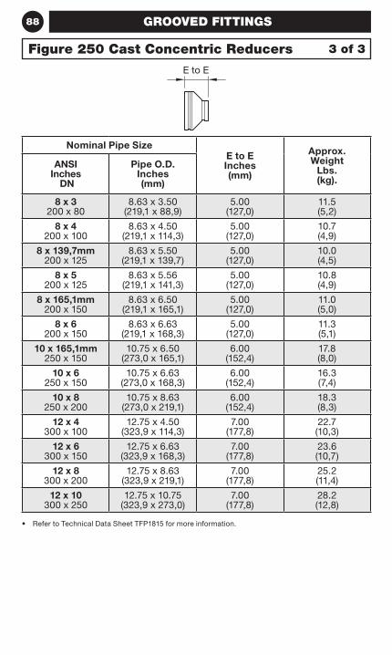
88 GROOVED FITTINGS
• Refer to Technical Data Sheet TFP1815 for more information.
Nominal Pipe SizeE to E Inches (mm)
Approx. Weight
Lbs. (kg).
ANSI Inches
DN
Pipe O.D. Inches (mm)
8 x 3 200 x 80
8.63 x 3.50 (219,1 x 88,9)
5.00 (127,0)
11.5 (5,2)
8 x 4 200 x 100
8.63 x 4.50 (219,1 x 114,3)
5.00 (127,0)
10.7 (4,9)
8 x 139,7mm 200 x 125
8.63 x 5.50 (219,1 x 139,7)
5.00 (127,0)
10.0 (4,5)
8 x 5 200 x 125
8.63 x 5.56 (219,1 x 141,3)
5.00 (127,0)
10.8 (4,9)
8 x 165,1mm 200 x 150
8.63 x 6.50 (219,1 x 165,1)
5.00 (127,0)
11.0 (5,0)
8 x 6 200 x 150
8.63 x 6.63 (219,1 x 168,3)
5.00 (127,0)
11.3 (5,1)
10 x 165,1mm 250 x 150
10.75 x 6.50 (273,0 x 165,1)
6.00 (152,4)
17.8 (8,0)
10 x 6 250 x 150
10.75 x 6.63 (273,0 x 168,3)
6.00 (152,4)
16.3 (7,4)
10 x 8 250 x 200
10.75 x 8.63 (273,0 x 219,1)
6.00 (152,4)
18.3 (8,3)
12 x 4 300 x 100
12.75 x 4.50 (323,9 x 114,3)
7.00 (177,8)
22.7 (10,3)
12 x 6 300 x 150
12.75 x 6.63 (323,9 x 168,3)
7.00 (177,8)
23.6 (10,7)
12 x 8 300 x 200
12.75 x 8.63 (323,9 x 219,1)
7.00 (177,8)
25.2 (11,4)
12 x 10 300 x 250
12.75 x 10.75 (323,9 x 273,0)
7.00 (177,8)
28.2 (12,8)
Figure 250 Cast Concentric Reducers 3 of 3
E to E
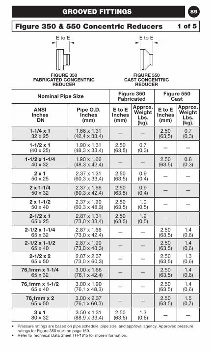
89
FIGURE 350 FABRICATED CONCENTRIC
REDUCER
GROOVED FITTINGS
FIGURE 550 CAST CONCENTRIC
REDUCER
• Pressure ratings are based on pipe schedule, pipe size, and approval agency. Approved pressure ratings for Figure 350 start on page 169.
• Refer to Technical Data Sheet TFP1815 for more information.
Nominal Pipe Size Figure 350 Fabricated
Figure 550 Cast
ANSI Inches
DN
Pipe O.D. Inches (mm)
E to E Inches (mm)
Approx. Weight
Lbs. (kg).
E to E Inches (mm)
Approx. Weight
Lbs. (kg).
1-1/4 x 1 32 x 25
1.66 x 1.31 (42,4 x 33,4) — — 2.50
(63,5)0.7
(0,3)
1-1/2 x 1 (40 x 25)
1.90 x 1.31 (48,3 x 33,4)
2.50 (63,5)
0.7 (0,3) — —
1-1/2 x 1-1/4 40 x 32
1.90 x 1.66 (48,3 x 42,4) — — 2.50
(63,5)0.8 (0,3)
2 x 1 50 x 25
2.37 x 1.31 (60,3 x 33,4)
2.50 (63,5)
0.9 (0,4) — —
2 x 1-1/4 50 x 32
2.37 x 1.66 (60,3 x 42,4)
2.50 (63,5)
0.9 (0,4) — —
2 x 1-1/2 50 x 40
2.37 x 1.90 (60,3 x 48,3)
2.50 (63,5)
1.0 (0,5) — —
2-1/2 x 1 65 x 25
2.87 x 1.31 (73,0 x 33,4)
2.50 (63,5)
1.2 (0,5) — —
2-1/2 x 1-1/4 65 x 32
2.87 x 1.66 (73,0 x 42,4) — — 2.50
(63,5)1.4
(0,6)
2-1/2 x 1-1/2 65 x 40
2.87 x 1.90 (73,0 x 48,3) — — 2.50
(63,5)1.4
(0,6)
2-1/2 x 2 65 x 50
2.87 x 2.37 (73,0 x 60,3) — — 2.50
(63,5)1.3
(0,6)
76,1mm x 1-1/4 65 x 32
3.00 x 1.66 (76,1 x 42,4) — — 2.50
(63,5)1.4
(0,6)
76,1mm x 1-1/2 65 x 40
3.00 x 1.90 (76,1 x 48,3) — — 2.50
(63,5)1.4
(0,6)
76,1mm x 2 65 x 50
3.00 x 2.37 (76,1 x 60,3) — — 2.50
(63,5)1.5
(0,7)
3 x 1 80 x 32
3.50 x 1.31 (88,9 x 33,4)
2.50 (63,5)
1.3 (0,6) — —
1 of 5Figure 350 & 550 Concentric Reducers
E to E E to E
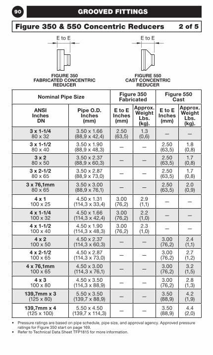
90 GROOVED FITTINGS
• Pressure ratings are based on pipe schedule, pipe size, and approval agency. Approved pressure ratings for Figure 350 start on page 169.
• Refer to Technical Data Sheet TFP1815 for more information.
Nominal Pipe Size Figure 350 Fabricated
Figure 550 Cast
ANSI Inches
DN
Pipe O.D. Inches (mm)
E to E Inches (mm)
Approx. Weight
Lbs. (kg).
E to E Inches (mm)
Approx. Weight
Lbs. (kg).
3 x 1-1/4 80 x 32
3.50 x 1.66 (88,9 x 42,4)
2.50 (63,5)
1.3 (0,6) — —
3 x 1-1/2 80 x 40
3.50 x 1.90 (88,9 x 48,3) — — 2.50
(63,5)1.8
(0,8)
3 x 2 80 x 50
3.50 x 2.37 (88,9 x 60,3) — — 2.50
(63,5)1.7
(0,8)
3 x 2-1/2 80 x 65
3.50 x 2.87 (88,9 x 73,0) — — 2.50
(63,5)1.7
(0,8)
3 x 76,1mm 80 x 65
3.50 x 3.00 (88,9 x 76,1) — — 2.50
(63,5)2.0 (0,9)
4 x 1 100 x 25
4.50 x 1.31 (114,3 x 33,4)
3.00 (76,2)
2.9 (1,1) — —
4 x 1-1/4 100 x 32
4.50 x 1.66 (114,3 x 42,4)
3.00 (76,2)
2.2 (1,0) — —
4 x 1-1/2 100 x 40
4.50 x 1.90 (114,3 x 48,3)
3.00 (76,2)
2.3 (1,0) — —
4 x 2 100 x 50
4.50 x 2.37 (114,3 x 60,3) — — 3.00
(76,2)2.4 (1,1)
4 x 2-1/2 100 x 65
4.50 x 2.87 (114,3 x 73,0) — — 3.00
(76,2)2.7 (1,2)
4 x 76,1mm 100 x 65
4.50 x 3.00 (114,3 x 76,1) — — 3.00
(76,2)3.2 (1,5)
4 x 3 100 x 80
4.50 x 3.50 (114,3 x 88,9) — — 3.00
(76,2)2.8 (1,3)
139,7mm x 3 (125 x 80)
5.50 x 3.50 (139,7 x 88,9) — — 3.50
(88,9)4.2 (1,9)
139,7mm x 4 (125 x 100)
5.50 x 4.50 (139,7 x 114,3) — — 3.50
(88,9)4.4 (2,0)
2 of 5Figure 350 & 550 Concentric Reducers
FIGURE 350 FABRICATED CONCENTRIC
REDUCER
FIGURE 550 CAST CONCENTRIC
REDUCER
E to E E to E
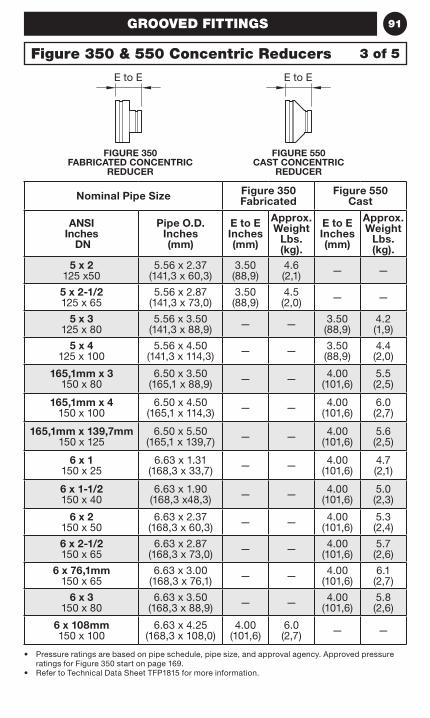
91GROOVED FITTINGS
• Pressure ratings are based on pipe schedule, pipe size, and approval agency. Approved pressure ratings for Figure 350 start on page 169.
• Refer to Technical Data Sheet TFP1815 for more information.
Nominal Pipe Size Figure 350 Fabricated
Figure 550 Cast
ANSI Inches
DN
Pipe O.D. Inches (mm)
E to E Inches (mm)
Approx. Weight
Lbs. (kg).
E to E Inches (mm)
Approx. Weight
Lbs. (kg).
5 x 2 125 x50
5.56 x 2.37 (141,3 x 60,3)
3.50 (88,9)
4.6 (2,1) — —
5 x 2-1/2 125 x 65
5.56 x 2.87 (141,3 x 73,0)
3.50 (88,9)
4.5 (2,0) — —
5 x 3 125 x 80
5.56 x 3.50 (141,3 x 88,9) — — 3.50
(88,9)4.2 (1,9)
5 x 4 125 x 100
5.56 x 4.50 (141,3 x 114,3) — — 3.50
(88,9)4.4 (2,0)
165,1mm x 3 150 x 80
6.50 x 3.50 (165,1 x 88,9) — — 4.00
(101,6)5.5 (2,5)
165,1mm x 4 150 x 100
6.50 x 4.50 (165,1 x 114,3) — — 4.00
(101,6)6.0 (2,7)
165,1mm x 139,7mm 150 x 125
6.50 x 5.50 (165,1 x 139,7) — — 4.00
(101,6)5.6 (2,5)
6 x 1 150 x 25
6.63 x 1.31 (168,3 x 33,7) — — 4.00
(101,6)4.7 (2,1)
6 x 1-1/2 150 x 40
6.63 x 1.90 (168,3 x48,3) — — 4.00
(101,6)5.0 (2,3)
6 x 2 150 x 50
6.63 x 2.37 (168,3 x 60,3) — — 4.00
(101,6)5.3 (2,4)
6 x 2-1/2 150 x 65
6.63 x 2.87 (168,3 x 73,0) — — 4.00
(101,6)5.7 (2,6)
6 x 76,1mm 150 x 65
6.63 x 3.00 (168,3 x 76,1) — — 4.00
(101,6)6.1
(2,7)
6 x 3 150 x 80
6.63 x 3.50 (168,3 x 88,9) — — 4.00
(101,6)5.8 (2,6)
6 x 108mm 150 x 100
6.63 x 4.25 (168,3 x 108,0)
4.00 (101,6)
6.0 (2,7) — —
Figure 350 & 550 Concentric Reducers 3 of 5
FIGURE 350 FABRICATED CONCENTRIC
REDUCER
FIGURE 550 CAST CONCENTRIC
REDUCER
E to E E to E
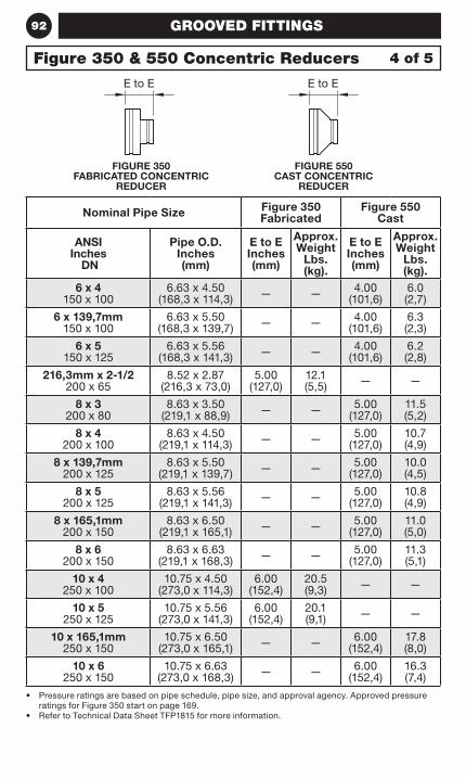
92
• Pressure ratings are based on pipe schedule, pipe size, and approval agency. Approved pressure ratings for Figure 350 start on page 169.
• Refer to Technical Data Sheet TFP1815 for more information.
Nominal Pipe Size Figure 350 Fabricated
Figure 550 Cast
ANSI Inches
DN
Pipe O.D. Inches (mm)
E to E Inches (mm)
Approx. Weight
Lbs. (kg).
E to E Inches (mm)
Approx. Weight
Lbs. (kg).
6 x 4 150 x 100
6.63 x 4.50 (168,3 x 114,3) — — 4.00
(101,6)6.0 (2,7)
6 x 139,7mm 150 x 100
6.63 x 5.50 (168,3 x 139,7) — — 4.00
(101,6)6.3 (2,3)
6 x 5 150 x 125
6.63 x 5.56 (168,3 x 141,3) — — 4.00
(101,6)6.2 (2,8)
216,3mm x 2-1/2 200 x 65
8.52 x 2.87 (216,3 x 73,0)
5.00 (127,0)
12.1 (5,5) — —
8 x 3 200 x 80
8.63 x 3.50 (219,1 x 88,9) — — 5.00
(127,0)11.5 (5,2)
8 x 4 200 x 100
8.63 x 4.50 (219,1 x 114,3) — — 5.00
(127,0)10.7 (4,9)
8 x 139,7mm 200 x 125
8.63 x 5.50 (219,1 x 139,7) — — 5.00
(127,0)10.0 (4,5)
8 x 5 200 x 125
8.63 x 5.56 (219,1 x 141,3) — — 5.00
(127,0)10.8 (4,9)
8 x 165,1mm 200 x 150
8.63 x 6.50 (219,1 x 165,1) — — 5.00
(127,0)11.0 (5,0)
8 x 6 200 x 150
8.63 x 6.63 (219,1 x 168,3) — — 5.00
(127,0)11.3 (5,1)
10 x 4 250 x 100
10.75 x 4.50 (273,0 x 114,3)
6.00 (152,4)
20.5 (9,3) — —
10 x 5 250 x 125
10.75 x 5.56 (273,0 x 141,3)
6.00 (152,4)
20.1 (9,1) — —
10 x 165,1mm 250 x 150
10.75 x 6.50 (273,0 x 165,1) — — 6.00
(152,4)17.8 (8,0)
10 x 6 250 x 150
10.75 x 6.63 (273,0 x 168,3) — — 6.00
(152,4)16.3 (7,4)
Figure 350 & 550 Concentric Reducers 4 of 5
FIGURE 350 FABRICATED CONCENTRIC
REDUCER
FIGURE 550 CAST CONCENTRIC
REDUCER
GROOVED FITTINGS
E to E E to E
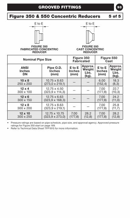
93
• Pressure ratings are based on pipe schedule, pipe size, and approval agency. Approved pressure ratings for Figure 350 start on page 169.
• Refer to Technical Data Sheet TFP1815 for more information.
Nominal Pipe Size Figure 350 Fabricated
Figure 550 Cast
ANSI Inches
DN
Pipe O.D. Inches (mm)
E to E Inches (mm)
Approx. Weight
Lbs. (kg).
E to E Inches (mm)
Approx. Weight
Lbs. (kg).
10 x 8 250 x 200
10.75 x 8.63 (273,0 x 219,1) — — 6.00
(152,4)18.3 (8,3)
12 x 4 300 x 100
12.75 x 4.50 (323,9 x 114,3) — — 7.00
(177,8)22.7 (10,3)
12 x 6 300 x 150
12.75 x 6.63 (323,9 x 168,3) — — 7.00
(177,8)24.2 (11,0)
12 x 8 300 x 200
12.75 x 8.63 (323,9 x 219,1) — — 7.00
(177,8)25.8 (11,7)
12 x 10 300 x 250
12.75 x 10.75 (323,9 x 273,0)
7.00 (177,8)
28.2 (12,8)
7.00 (177,8)
28.2 (12,8)
Figure 350 & 550 Concentric Reducers 5 of 5
FIGURE 350 FABRICATED CONCENTRIC
REDUCER
FIGURE 550 CAST CONCENTRIC
REDUCER
GROOVED FITTINGS
E to E E to E
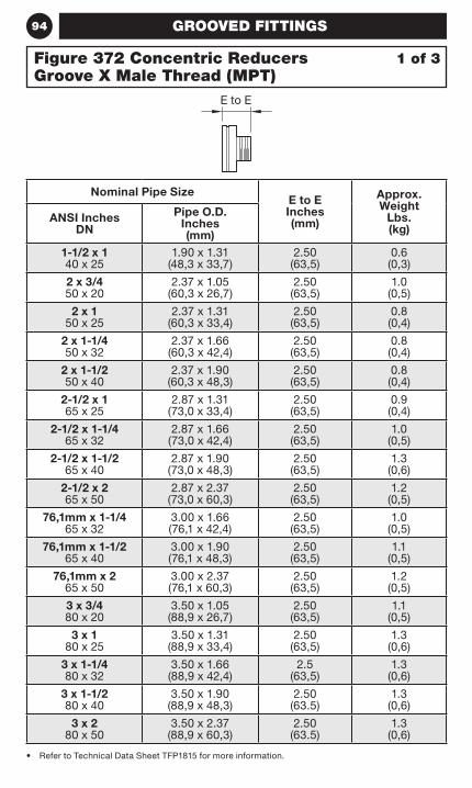
94
• Refer to Technical Data Sheet TFP1815 for more information.
Nominal Pipe SizeE to E Inches (mm)
Approx. Weight
Lbs. (kg)
ANSI Inches DN
Pipe O.D. Inches (mm)
1-1/2 x 1 40 x 25
1.90 x 1.31 (48,3 x 33,7)
2.50 (63,5)
0.6 (0,3)
2 x 3/4 50 x 20
2.37 x 1.05 (60,3 x 26,7)
2.50 (63,5)
1.0 (0,5)
2 x 1 50 x 25
2.37 x 1.31 (60,3 x 33,4)
2.50 (63,5)
0.8 (0,4)
2 x 1-1/4 50 x 32
2.37 x 1.66 (60,3 x 42,4)
2.50 (63,5)
0.8 (0,4)
2 x 1-1/2 50 x 40
2.37 x 1.90 (60,3 x 48,3)
2.50 (63,5)
0.8 (0,4)
2-1/2 x 1 65 x 25
2.87 x 1.31 (73,0 x 33,4)
2.50 (63,5)
0.9 (0,4)
2-1/2 x 1-1/4 65 x 32
2.87 x 1.66 (73,0 x 42,4)
2.50 (63,5)
1.0 (0,5)
2-1/2 x 1-1/2 65 x 40
2.87 x 1.90 (73,0 x 48,3)
2.50 (63,5)
1.3 (0,6)
2-1/2 x 2 65 x 50
2.87 x 2.37 (73,0 x 60,3)
2.50 (63,5)
1.2 (0,5)
76,1mm x 1-1/4 65 x 32
3.00 x 1.66 (76,1 x 42,4)
2.50 (63,5)
1.0 (0,5)
76,1mm x 1-1/2 65 x 40
3.00 x 1.90 (76,1 x 48,3)
2.50 (63,5)
1.1 (0,5)
76,1mm x 2 65 x 50
3.00 x 2.37 (76,1 x 60,3)
2.50 (63,5)
1.2 (0,5)
3 x 3/4 80 x 20
3.50 x 1.05 (88,9 x 26,7)
2.50 (63,5)
1.1 (0,5)
3 x 1 80 x 25
3.50 x 1.31 (88,9 x 33,4)
2.50 (63,5)
1.3 (0,6)
3 x 1-1/4 80 x 32
3.50 x 1.66 (88,9 x 42,4)
2.5 (63,5)
1.3 (0,6)
3 x 1-1/2 80 x 40
3.50 x 1.90 (88,9 x 48,3)
2.50 (63.5)
1.3 (0,6)
3 x 2 80 x 50
3.50 x 2.37 (88,9 x 60,3)
2.50 (63.5)
1.3 (0,6)
1 of 3Figure 372 Concentric Reducers Groove X Male Thread (MPT)
GROOVED FITTINGS
E to E
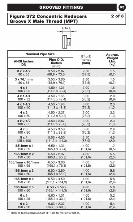
95
• Refer to Technical Data Sheet TFP1815 for more information.
Nominal Pipe SizeE to E Inches (mm)
Approx. Weight
Lbs. (kg)
ANSI Inches DN
Pipe O.D. Inches (mm)
3 x 2-1/2 80 x 65
3.50 x 2.87 (88,9 x 73,0)
2.50 (63.5)
1.5 (0,7)
3 x 76,1mm 80 x 65
3.50 x 3.00 (88,9 x 76,1)
2.50 (63.5)
1.5 (0,7)
4 x 1 100 x 25
4.50 x 1.31 (114,3 x 33,4)
3.00 (76,2)
1.8 (0,8)
4 x 1-1/4 100 x 32
4.50 x 1.66 (114,3 x 42,4)
3.00 (76,2)
2.0 (0,9)
4 x 1-1/2 100 x 40
4.50 x 1.90 (114,3 x 48,3)
3.00 (76,2)
2.3 (1,0)
4 x 2 100 x 50
4.50 x 2.37 (114,3 x 60,3)
3.00 (76,2)
2.3 (1,0)
4 x 2-1/2 100 x 65
4.50 x 2.87 (114,3 x 73,0)
3.00 (76,2)
2.3 (1,0)
4 x 3 100 x 80
4.50 x 3.50 (114,3 x 88,9)
3.00 (76,2)
2.6 (1,2)
5 x 4 125 x 100
5.56 x 4.50 (141,3 x 114,3)
3.50 (88,9)
4.5 (2,0)
165,1mm x 1 150 x 25
6.50 x 1.31 (165,1 x 33,4)
4.00 (101,6)
1.2 (0,5)
165,1mm x 2 150 x 50
6.50 x 2.37 (165,1 x 60,3)
4.00 (101,6)
5.5 (2,5)
165,1mm x 76,1mm 150 x 65
6.50 x 3.00 (165,1 x 76,1)
4.00 (101,6)
5.7 (2,6)
165,1mm x 3 150 x 50
6.50 x 3.50 (165,1 x 88,9)
4.00 (101,6)
5.8 (2,6)
165,1mm x 4 150 x 50
6.50 x 4.50 (165,1 x 114,3)
4.00 (101,6)
5.8 (2,6)
165,1mm x 5 150 x 50
6.50 x 5.563 (165,1 x 141,3)
4.00 (101,6)
5.8 (2,6)
6 x 1 150 x 25
6.63 x 1.31 (168,3 x 33,4)
4.00 (101,6)
5.2 (2,4)
6 x 2 150 x 50
6.63 x 2.37 (168,3 x 60,3)
4.00 (101,6)
5.4 (2,4)
Figure 372 Concentric Reducers Groove X Male Thread (MPT)
2 of 3
GROOVED FITTINGS
E to E
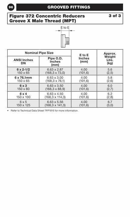
96
• Refer to Technical Data Sheet TFP1815 for more information.
Nominal Pipe SizeE to E Inches (mm)
Approx. Weight
Lbs. (kg)
ANSI Inches DN
Pipe O.D. Inches (mm)
6 x 2-1/2 150 x 65
6.63 x 2.87 (168,3 x 73,0)
4.00 (101,6)
5.6 (2,5)
6 x 76,1mm 150 x 65
6.63 x 3.00 (168,3 x 76,1)
4.00 (101,6)
5.8 (2,6)
6 x 3 150 x 80
6.63 x 3.50 (168,3 x 88,9)
4.00 (101,6)
6.0 (2,7)
6 x 4 150 x 100
6.63 x 4.50 (168,3 x 114,3)
4.00 (101,6)
6.2 (2,8)
6 x 5 150 x 125
6.63 x 5.56 (168,3 x 141,3)
4.00 (101,6)
6.7 (3,0)
GROOVED FITTINGS
Figure 372 Concentric Reducers Groove X Male Thread (MPT)
3 of 3
E to E
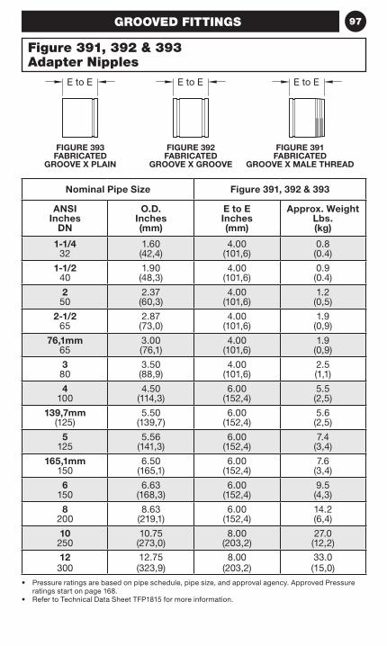
97
Figure 391, 392 & 393 Adapter Nipples
FIGURE 391 FABRICATED
GROOVE X MALE THREAD
FIGURE 392 FABRICATED
GROOVE X GROOVE
FIGURE 393 FABRICATED
GROOVE X PLAIN
• Pressure ratings are based on pipe schedule, pipe size, and approval agency. Approved Pressure ratings start on page 168.
• Refer to Technical Data Sheet TFP1815 for more information.
Nominal Pipe Size Figure 391, 392 & 393
ANSI Inches
DN
O.D. Inches (mm)
E to E Inches (mm)
Approx. Weight Lbs. (kg)
1-1/4 32
1.60 (42,4)
4.00 (101,6)
0.8 (0.4)
1-1/2 40
1.90 (48,3)
4.00 (101,6)
0.9 (0.4)
2 50
2.37 (60,3)
4.00 (101,6)
1.2 (0,5)
2-1/2 65
2.87 (73,0)
4.00 (101,6)
1.9 (0,9)
76,1mm 65
3.00 (76,1)
4.00 (101,6)
1.9 (0,9)
3 80
3.50 (88,9)
4.00 (101,6)
2.5 (1,1)
4 100
4.50 (114,3)
6.00 (152,4)
5.5 (2,5)
139,7mm (125)
5.50 (139,7)
6.00 (152,4)
5.6 (2,5)
5 125
5.56 (141,3)
6.00 (152,4)
7.4 (3,4)
165,1mm 150
6.50 (165,1)
6.00 (152,4)
7.6 (3,4)
6 150
6.63 (168,3)
6.00 (152,4)
9.5 (4,3)
8 200
8.63 (219,1)
6.00 (152,4)
14.2 (6,4)
10 250
10.75 (273,0)
8.00 (203,2)
27.0 (12,2)
12 300
12.75 (323,9)
8.00 (203,2)
33.0 (15,0)
GROOVED FITTINGS
E to EE to EE to E
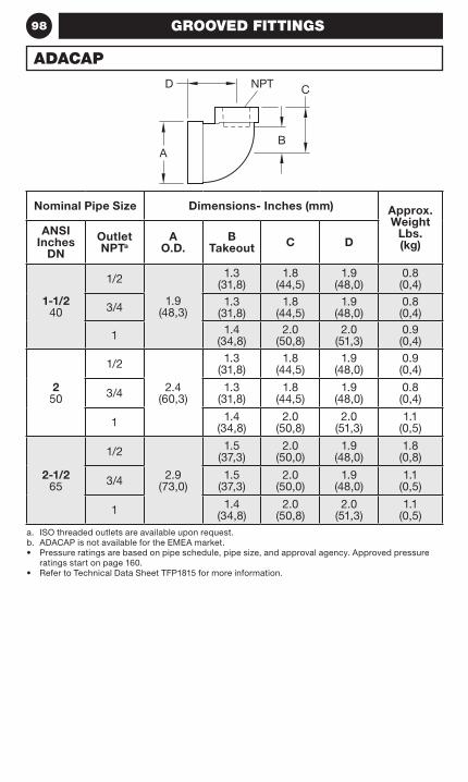
98
Nominal Pipe Size Dimensions- Inches (mm) Approx. Weight
Lbs. (kg)
ANSI Inches
DN
Outlet NPTa
A O.D.
B Takeout C D
1-1/2 40
1/2
1.9 (48,3)
1.3 (31,8)
1.8 (44,5)
1.9 (48,0)
0.8 (0,4)
3/4 1.3 (31,8)
1.8 (44,5)
1.9 (48,0)
0.8 (0,4)
1 1.4 (34,8)
2.0 (50,8)
2.0 (51,3)
0.9 (0,4)
2 50
1/2
2.4 (60,3)
1.3 (31,8)
1.8 (44,5)
1.9 (48,0)
0.9 (0,4)
3/4 1.3 (31,8)
1.8 (44,5)
1.9 (48,0)
0.8 (0,4)
1 1.4 (34,8)
2.0 (50,8)
2.0 (51,3)
1.1 (0,5)
2-1/2 65
1/2
2.9 (73,0)
1.5 (37,3)
2.0 (50,0)
1.9 (48,0)
1.8 (0,8)
3/4 1.5 (37,3)
2.0 (50,0)
1.9 (48,0)
1.1 (0,5)
1 1.4 (34,8)
2.0 (50,8)
2.0 (51,3)
1.1 (0,5)
a. ISO threaded outlets are available upon request.b. ADACAP is not available for the EMEA market.• Pressure ratings are based on pipe schedule, pipe size, and approval agency. Approved pressure
ratings start on page 160.• Refer to Technical Data Sheet TFP1815 for more information.
GROOVED FITTINGS
ADACAP
B
D
A
CNPT
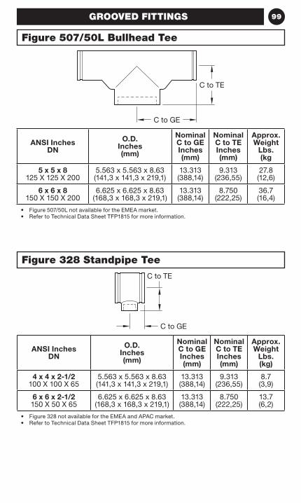
99
ANSI Inches DN
O.D. Inches (mm)
Nominal C to GE Inches (mm)
Nominal C to TE Inches (mm)
Approx. Weight
Lbs. (kg
5 x 5 x 8 125 X 125 X 200
5.563 x 5.563 x 8.63 (141,3 x 141,3 x 219,1)
13.313 (388,14)
9.313 (236,55)
27.8 (12,6)
6 x 6 x 8 150 X 150 X 200
6.625 x 6.625 x 8.63 (168,3 x 168,3 x 219,1)
13.313 (388,14)
8.750 (222,25)
36.7 (16,4)
• Figure 507/50L not available for the EMEA market.• Refer to Technical Data Sheet TFP1815 for more information.
ANSI Inches DN
O.D. Inches (mm)
Nominal C to GE Inches (mm)
Nominal C to TE Inches (mm)
Approx. Weight
Lbs. (kg)
4 x 4 x 2-1/2 100 X 100 X 65
5.563 x 5.563 x 8.63 (141,3 x 141,3 x 219,1)
13.313 (388,14)
9.313 (236,55)
8.7 (3,9)
6 x 6 x 2-1/2 150 X 50 X 65
6.625 x 6.625 x 8.63 (168,3 x 168,3 x 219,1)
13.313 (388,14)
8.750 (222,25)
13.7 (6,2)
• Figure 328 not available for the EMEA and APAC market.• Refer to Technical Data Sheet TFP1815 for more information.
GROOVED FITTINGS
Figure 507/50L Bullhead Tee
Figure 328 Standpipe Tee
C to GE
C to TE
C to TE
C to GE

100 NOTES
101OUTLET FITTINGS
OutletFittings
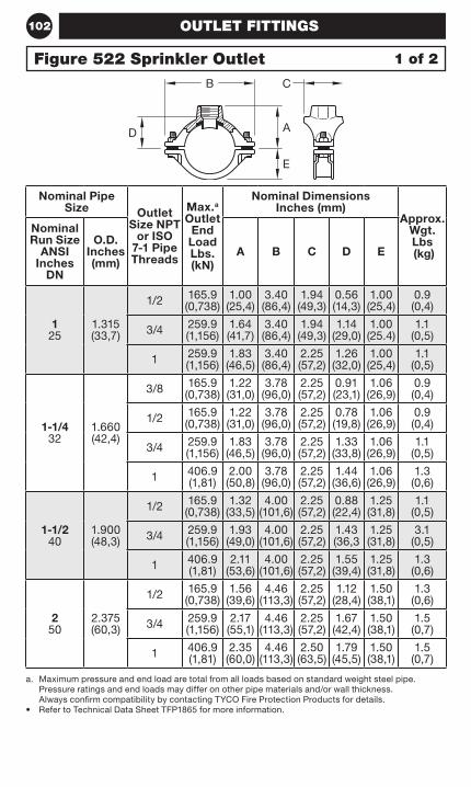
102 OUTLET FITTINGS
Nominal Pipe Size Outlet
Size NPT or ISO
7-1 Pipe Threads
Max.a Outlet
End Load Lbs. (kN)
Nominal Dimensions Inches (mm)
Approx. Wgt. Lbs (kg)
Nominal Run Size
ANSI Inches
DN
O.D. Inches (mm)
A B C D E
1 25
1.315 (33,7)
1/2 165.9 (0,738)
1.00 (25,4)
3.40 (86,4)
1.94 (49,3)
0.56 (14,3)
1.00 (25,4)
0.9 (0,4)
3/4 259.9 (1,156)
1.64 (41,7)
3.40 (86,4)
1.94 (49,3)
1.14 (29,0)
1.00 (25.4)
1.1 (0,5)
1 259.9 (1,156)
1.83 (46,5)
3.40 (86,4)
2.25 (57,2)
1.26 (32,0)
1.00 (25,4)
1.1 (0,5)
1-1/4 32
1.660 (42,4)
3/8 165.9 (0,738)
1.22 (31,0)
3.78 (96,0)
2.25 (57,2)
0.91 (23,1)
1.06 (26,9)
0.9 (0,4)
1/2 165.9 (0,738)
1.22 (31,0)
3.78 (96,0)
2.25 (57,2)
0.78 (19,8)
1.06 (26,9)
0.9 (0,4)
3/4 259.9 (1,156)
1.83 (46,5)
3.78 (96,0)
2.25 (57,2)
1.33 (33,8)
1.06 (26,9)
1.1 (0,5)
1 406.9 (1,81)
2.00 (50,8)
3.78 (96,0)
2.25 (57,2)
1.44 (36,6)
1.06 (26,9)
1.3 (0,6)
1-1/2 40
1.900 (48,3)
1/2 165.9 (0,738)
1.32 (33,5)
4.00 (101,6)
2.25 (57,2)
0.88 (22,4)
1.25 (31,8)
1.1 (0,5)
3/4 259.9 (1,156)
1.93 (49,0)
4.00 (101,6)
2.25 (57,2)
1.43 (36,3
1.25 (31,8)
3.1 (0,5)
1 406.9 (1,81)
2.11 (53,6)
4.00 (101,6)
2.25 (57,2)
1.55 (39,4)
1.25 (31,8)
1.3 (0,6)
2 50
2.375 (60,3)
1/2 165.9 (0,738)
1.56 (39,6)
4.46 (113,3)
2.25 (57,2)
1.12 (28,4)
1.50 (38,1)
1.3 (0,6)
3/4 259.9 (1,156)
2.17 (55,1)
4.46 (113,3)
2.25 (57,2)
1.67 (42,4)
1.50 (38,1)
1.5 (0,7)
1 406.9 (1,81)
2.35 (60,0)
4.46 (113,3)
2.50 (63,5)
1.79 (45,5)
1.50 (38,1)
1.5 (0,7)
a. Maximum pressure and end load are total from all loads based on standard weight steel pipe. Pressure ratings and end loads may differ on other pipe materials and/or wall thickness. Always confirm compatibility by contacting TYCO Fire Protection Products for details.
• Refer to Technical Data Sheet TFP1865 for more information.
Figure 522 Sprinkler Outlet 1 of 2
B C
E
AD
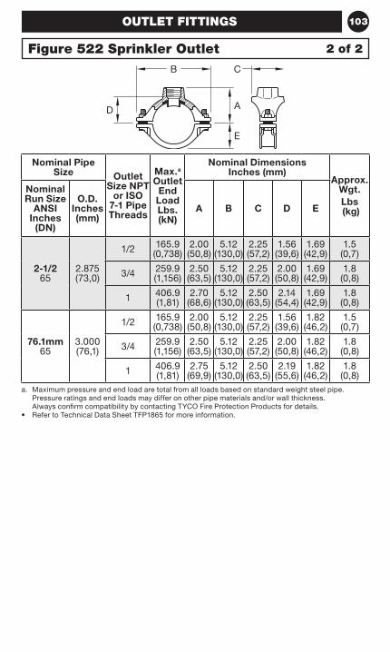
103OUTLET FITTINGS
Nominal Pipe Size Outlet
Size NPT or ISO
7-1 Pipe Threads
Max.a Outlet
End Load Lbs. (kN)
Nominal Dimensions Inches (mm)
Approx. Wgt.Lbs (kg)
Nominal Run Size
ANSI Inches
(DN)
O.D. Inches (mm)
A B C D E
2-1/2 65
2.875 (73,0)
1/2 165.9 (0,738)
2.00 (50,8)
5.12 (130,0)
2.25 (57,2)
1.56 (39,6)
1.69 (42,9)
1.5 (0,7)
3/4 259.9 (1,156)
2.50 (63,5)
5.12 (130,0)
2.25 (57,2)
2.00 (50,8)
1.69 (42,9)
1.8 (0,8)
1 406.9 (1,81)
2.70 (68,6)
5.12 (130,0)
2.50 (63,5)
2.14 (54,4)
1.69 (42,9)
1.8 (0,8)
76.1mm 65
3.000 (76,1)
1/2 165.9 (0,738)
2.00 (50,8)
5.12 (130,0)
2.25 (57,2)
1.56 (39,6)
1.82 (46,2)
1.5 (0,7)
3/4 259.9 (1,156)
2.50 (63,5)
5.12 (130,0)
2.25 (57,2)
2.00 (50,8)
1.82 (46,2)
1.8 (0,8)
1 406.9 (1,81)
2.75 (69,9)
5.12 (130,0)
2.50 (63,5)
2.19 (55,6)
1.82 (46,2)
1.8 (0,8)
a. Maximum pressure and end load are total from all loads based on standard weight steel pipe. Pressure ratings and end loads may differ on other pipe materials and/or wall thickness. Always confirm compatibility by contacting TYCO Fire Protection Products for details.
• Refer to Technical Data Sheet TFP1865 for more information.
Figure 522 Sprinkler Outlet 2 of 2
B C
E
AD

104 OUTLET FITTINGS
Nominal Run x Branch
ANSI Inches
DN
O.D. Inches (mm)
Nominal Dimensions- Inches (mm)
A B C D E
2 x 1/2 50 x 15
2.375 x 0.840 (60,3 x 21,3)
2.62 (66,5)
4.88 (124,0)
3.07 (78,0)
2.12 (53,8)
1.59 (40,4)
2 x 3/4 50 x 20
2.375 x 1.050 (60,3 x 26,7)
2.62 (66,5)
4.88 (124,0)
3.07 (78,0)
2.12 (53,8)
1.59 (40,4)
2 x 1 50 x 25
2.375 x 1.315 (60,3 x 33,7)
2.62 (66,5)
4.88 (124,0)
3.07 (78,0)
2.12 (53,8)
1.59 (40,4)
2 x 1-1/4 50 x 32
2.375 x 1.660 (60,3 x 42,2)
2.78 (70,6)
4.88 (124,0)
3.32 (84,3)
1.93 (49,0)
1.59 (40,4)
2 x 1-1/2 50 x 40
2.375 x 1.900 (60,3 x 48,3)
2.75 (69,9)
4.88 (124,0)
3.32 (84,3)
1.93 (49,0)
1.59 (40,4)
2-1/2 x 1/2 65 x 15
2.875 x 0.840 (73,0 x 21,3)
2.88 (73,2)
5.25 (133,4)
3.07 (78,0)
2.38 (60,5)
1.81 (46,0)
2-1/2 x 3/4 65 x 20
2.875 x 1.050 (73,0 x 26,7)
2.88 (73,2)
5.25 (133,4)
3.07 (78,0)
2.38 (60,5)
1.81 (46,0)
2-1/2 x 1 65 x 25
2.875 x 1.315 (73,0 x 33,7)
2.88 (73,2)
5.25 (133,4)
3.07 (78,0)
2.38 (60,5)
1.81 (46,0)
2-1/2 x 1-1/4 65 x 32
2.875 x 1.660 (73,0 x 42,2)
3.00 (76,2)
5.25 (133,4)
3.56 (90,4)
2.19 (55,6)
1.81 (46,0)
2-1/2 x 1-1/2 65 x 40
2.875 x 1.900 (73,0 x 48,3)
3.07 (78,0)
5.25 (133,4)
3.59 (91,2)
2.17 (55,1)
1.81 (46,0)
2-1/2 x 2 65 x 50
2.875 x 2.375 (73,0 x 60,3)
3.19 (81,0)
5.25 (133,4)
4.00 (101,6)
2.44 (62,0)
1.81 (46,0)
76,1mm x 1/2 65 x 15
3.000 x 0.840 (76,1 x 21,3)
2.94 (74,5)
5.62 (142,7)
3.07 (78,0)
2.44 (62,0)
1.87 (47,5)
76,1mm x 3/4 65 x 20
3.000 x 1.050 (76,1 x 26,7)
2.94 (74,5)
5.62 (142,7)
3.07 (78,0)
2.44 (62,0)
1.87 (47,5)
76,1mm x 1 65 x 25
3.000 x 1.315 (76,1 x 33,7)
2.94 (74,5)
5.62 (142,7)
3.07 (78,0)
2.44 (62,0)
1.87 (47,5)
a. Pressure ratings are based on pipe schedule, pipe size, and approval agency. Approved pressure ratings start on page 142.
• Refer to Technical Data Sheet TFP1860 for more information.
1 of 10Figure 730 Threaded Mechanical Tees & Crosses
FIGURE 730 TEE THREADED OUTLET
FIGURE 730 CROSS THREADED OUTLET
CB
A
E
D B C
A
A
D
D
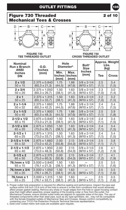
105
b. Proper outlet hole preparation is required for effective sealing and performance. Inspect the pipe seal surface within 5/8 inch (15,9 mm) of the hole to ensure it is free from conditions that would adversely affect proper gasket sealing. Remove any sharp or rough edges from the hole or upper housing contact area that might affect assembly, proper seating of the locating collar or flow from the outlet. For Mechanical Crosses, ensure double outlet holes are aligned on opposite sides of the pipe. The use of threaded components other than steel pipe, such as dry type sprinklers, etc., may not be compatible with the female threaded outlets of Mechanical Tees and Crosses. Always confirm compatibility by contacting your TYCO Fire Protection Products Technical Services representative.
c. Gold color coded metric bolt sizes are available upon request.
OUTLET FITTINGS
Nominal Run x Branch
ANSI Inches
DN
O.D. Inches (mm)
Hole Diameterb Boltc
Size Inches (mm)
Approx. Weight Lbs. (kg)
Min. Inches (mm)
Max. Inches (mm)
Tee Cross
2 x 1/2 50 x 15
2.375 x 0.840 (60,3 x 21,3)
1.75 (44,5)
1.88 (47,6)
3/8 x 2-1/4 (M10 x 57)
2.5 (1,1)
3.4 (1,5)
2 x 3/4 50 x 20
2.375 x 1.050 (60,3 x 26,7)
1.50 (38,1)
1.63 (41,3)
3/8 x 2-1/4 (M10 x 57)
2.3 (1,0)
3.0 (1,4)
2 x 1 50 x 25
2.375 x 1.315 (60,3 x 33,7)
1.50 (38,1)
1.63 (41,3)
3/8 x 2-1/4 (M10 x 57)
2.2 (1,0)
3.2 (1,5)
2 x 1-1/4 50 x 32
2.375 x 1.660 (60,3 x 42,2)
1.75 (44,5)
1.88 (47,6)
3/8 x 2-1/4 (M10 x 57)
2.4 (1,1)
3.4 (1,5)
2 x 1-1/2 50 x 40
2.375 x 1.900 (60,3 x 48,3)
1.75 (44,5)
1.88 (47,6)
3/8 x 2-1/4 (M10 x 57)
2.5 (1,1)
3.9 (1,8)
2-1/2 x 1/2 65 x 15
2.875 x 0.840 (73,0 x 21,3)
1.50 (38,1)
1.63 (41,3)
3/8 x 2-1/4 (M10 x 57)
2.4 (1,1)
3.4 (1,5)
2-1/2 x 3/4 65 x 20
2.875 x 1.050 (73,0 x 26,7)
1.50 (38,1)
1.63 (41,3)
3/8 x 2-1/4 (M10 x 57)
2.4 (1,1)
3.4 (1,5)
2-1/2 x 1 65 x 25
2.875 x 1.315 (73,0 x 33,7)
1.50 (38,1)
1.63 (41,3)
3/8 x 2-1/4 (M10 x 57)
2.4 (1,1)
3.4 (1,5)
2-1/2 x 1-1/4 65 x 32
2.875 x 1.660 (73,0 x 42,2)
2.00 (50,8)
2.13 (54,0)
3/8 x 2-1/4 (M10 x 57)
2.5 (1,1)
3.8 (1,7)
2-1/2 x 1-1/2 65 x 40
2.875 x 1.900 (73,0 x 48,3)
2.00 (50,8)
2.13 (54,0)
3/8 x 2-1/4 (M10 x 57)
2.6 (1,2)
4.1 (1,9)
2-1/2 x 2 65 x 50
2.875 x 2.375 (73,0 x 60,3)
2.00 (50,8)
2.13 (54,0)
3/8 x 2-1/4 (M10 x 57)
2.7 (1,2)
4.1 (1,9)
76,1mm x 1/2 65 x 15
3.000 x 0.840 (76,1 x 21,3)
1.50 (38,1)
1.63 (41,3)
— (M10 x 57)
2.5 (1,1)
3.5 (1,6)
76,1mm x 3/4 65 x 20
3.000 x 1.050 (76,1 x 26,7)
1.50 (38,1)
1.63 (41,3)
— (M10 x 57)
2.5 (1,1)
3.5 (1,6)
76,1mm x 1 65 x 25
3.000 x 1.315 (76,1 x 33,7)
1.50 (38,1)
1.63 (41,3)
— (M10 x 57)
2.5 (1,1)
3.5 (1,6)
2 of 10Figure 730 Threaded Mechanical Tees & Crosses
FIGURE 730 TEE THREADED OUTLET
FIGURE 730 CROSS THREADED OUTLET
CB
A
E
D B C
A
A
D
D

106 OUTLET FITTINGS
Nominal Run x Branch
ANSI Inches
DN
O.D. Inches (mm)
Nominal Dimensions- Inches (mm)
A B C D E
76,1mm x 1-1/4 65 x 32
3.000 x 1.660 (76,1 x 42,2)
3.06 (77,7)
5.62 (142,7)
3.56 (90,4)
2.25 (57,2)
1.87 (47,5)
76,1mm x 1-1/2 65 x 40
3.000 x 1.900 (76,1 x 48,3)
3.13 (79,5)
5.62 (142,7)
3.56 (90,4)
2.25 (57,2)
1.87 (47,5)
76,1mm x 2 65 x 50
3.000 x 2.375 (76,1 x 60,3)
3.25 (82,6)
5.62 (142,7)
4.00 (101,6)
2.50 (63,5)
1.87 (47,5)
3 x 1/2 80 x 15
3.500 x 0.840 (88,9 x 21,3)
3.19 (81,0)
6.13 (155,7)
3.07 (78,0)
2.56 (65,0)
2.21 (56,1)
3 x 3/4 80 x 20
3.500 x 1.050 (88,9 x 26,7)
3.19 (81,0)
6.13 (155,7)
3.07 (78,0)
2.56 (65,0)
2.21 (56,1)
3 x 1 80 x 25
3.500 x 1.315 (88,9 x 33,7)
3.19 (81,0)
6.13 (155,7)
3.07 (78,0)
2.56 (65,0)
2.21 (56,1)
3 x 1-1/4 80 x 32
3.500 x 1.660 (88,9 x 42,2)
3.34 (84,8)
6.13 (155,7)
3.32 (84,3)
2.50 (63,5)
2.21 (56,1)
3 x 1-1/280 x 40
3.500 x 1.900 (88,9 x 48,3)
3.38 (85.9)
6.13 (155,7)
3.56 (90,4)
2.48 (63,0)
2.21 (56,1)
3 x 2 80 x 50
3.500 x 2.375 (88,9 x 60,3)
3.50 (88,9)
6.13 (155,7)
4.09 (103,9)
2.75 (69,9)
2.21 (56,1)
4 x 1/2 100 x 15
4.500 x 0.840 (114,3 x 21,3)
3.69 (93,7)
7.13 (181,1)
3.07 (78,0)
3.06 (77,7)
2.78 (70,6)
4 x 3/4 100 x 20
4.500 x 1.050 (114,3 x 26,7)
3.69 (93,7)
7.13 (181,1)
3.07 (78,0)
3.06 (77,7)
2.78 (70,6)
4 x 1 100 x 25
4.500 x 1.315 (114,3 x 33,7)
3.69 (93,7)
7.13 (181,1)
3.07 (78,0)
3.06 (77,7)
2.78 (70,6)
4 x 1-1/4 100 x 32
4.500 x 1.660 (114,3 x 42,2)
3.92 (99,6)
7.13 (181,1)
3.32 (84,3)
3.00 (76,2)
2.78 (70,6)
4 x 1-1/2 100 x 40
4.500 x 1.900 (114,3 x 48,3)
4.00 (101,6)
7.13 (181,1)
3.56 (90,4)
2.98 (75,7)
2.78 (70,6)
a. Pressure ratings are based on pipe schedule, pipe size, and approval agency. Approved pressure ratings start on page 142.
• Refer to Technical Data Sheet TFP1860 for more information.
3 of 10Figure 730 Threaded Mechanical Tees & Crosses
FIGURE 730 TEE THREADED OUTLET
FIGURE 730 CROSS THREADED OUTLET
CB
A
E
D B C
A
A
D
D
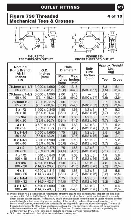
107
b. Proper outlet hole preparation is required for effective sealing and performance. Inspect the pipe seal surface within 5/8 inch (15,9 mm) of the hole to ensure it is free from conditions that would adversely affect proper gasket sealing. Remove any sharp or rough edges from the hole or upper housing contact area that might affect assembly, proper seating of the locating collar or flow from the outlet. For Mechanical Crosses, ensure double outlet holes are aligned on opposite sides of the pipe. The use of threaded components other than steel pipe, such as dry type sprinklers, etc., may not be compatible with the female threaded outlets of Mechanical Tees and Crosses. Always confirm compatibility by contacting your TYCO Fire Protection Products Technical Services representative.
c. Gold color coded metric bolt sizes are available upon request.
OUTLET FITTINGS
Nominal Run x Branch
ANSI Inches
DN
O.D. Inches (mm)
Hole Diameterb Boltc
Size Inches (mm)
Approx. Weight Lbs. (kg)
Min. Inches (mm)
Max. Inches (mm)
Tee Cross
76,1mm x 1-1/4 65 x 32
3.000 x 1.660 (76,1 x 42,2)
2.00 (50,8)
2.13 (54,0)
— (M10 x 57)
3.3 (1,5)
5.1 (2,3)
76,1mm x 1-1/2 65 x 40
3.000 x 1.900 (76,1 x 48,3)
2.00 (50,8)
2.13 (54,0)
— (M10 x 57)
3.6 (1,6)
5.7 (2,6)
76,1mm x 2 65 x 50
3.000 x 2.375 (76,1 x 60,3)
2.00 (50,8)
2.13 (54,0)
— (M10 x 57)
3.7 (1,7)
5.8 (2,6)
3 x 1/2 80 x 15
3.500 x 0.840 (88,9 x 21,3)
1.50 (38,1)
1.63 (41,3)
1/2 x 3 (M12 x 76)
3.7 (1,7)
5.2 (2,4)
3 x 3/4 80 x 20
3.500 x 1.050 (88,9 x 26,7)
1.50 (38,1)
1.63 (41,3)
1/2 x 3 (M12 x 76)
3.7 (1,7)
5.2 (2,4)
3 x 1 80 x 25
3.500 x 1.315 (88,9 x 33,7)
1.50 (38,1)
1.63 (41,3)
1/2 x 3 (M12 x 76)
3.7 (1,7)
5.2 (2,4)
3 x 1-1/4 80 x 32
3.500 x 1.660 (88,9 x 42,2)
1.75 (44,5)
1.88 (47,6)
1/2 x 3 (M12 x 76)
3.5 (1,6)
4.6 (2,1)
3 x 1-1/280 x 40
3.500 x 1.900 (88,9 x 48,3)
2.00 (50,8)
2.13 (54,0)
1/2 x 3 (M12 x 76)
3.7 (1,7)
5.2 (2,4)
3 x 2 80 x 50
3.500 x 2.375 (88,9 x 60,3)
1.75 (44,5)
1.88 (47,6)
1/2 x 3 (M12 x 76)
4.7 (2,1)
6.8 (3,1)
4 x 1/2 100 x 15
4.500 x 0.840 (114,3 x 21,3)
1.50 (38,1)
1.63 (41,3)
1/2 x 3 (M12 x 76)
4.8 (2,2)
5.6 (2,5)
4 x 3/4 100 x 20
4.500 x 1.050 (114,3 x 26,7)
1.50 (38,1)
1.63 (41,3)
1/2 x 3 (M12 x 76)
4.8 (2,2)
5.6 (2,5)
4 x 1 100 x 25
4.500 x 1.315 (114,3 x 33,7)
1.50 (38,1)
1.63 (41,3)
1/2 x 3 (M12 x 76)
4.8 (2,2)
5.6 (2,5)
4 x 1-1/4 100 x 32
4.500 x 1.660 (114,3 x 42,2)
1.75 (44,5)
1.88 (47,6)
1/2 x 3 (M12 x 76)
4.8 (2,2)
5.6 (2,5)
4 x 1-1/2 100 x 40
4.500 x 1.900 (114,3 x 48,3)
2.00 (50,8)
2.13 (54,0)
1/2 x 3 (M12 x 76)
5.1 (2,3)
6.4 (2,5)
4 of 10Figure 730 Threaded Mechanical Tees & Crosses
FIGURE 730 TEE THREADED OUTLET
FIGURE 730 CROSS THREADED OUTLET
CB
A
E
D B C
A
A
D
D
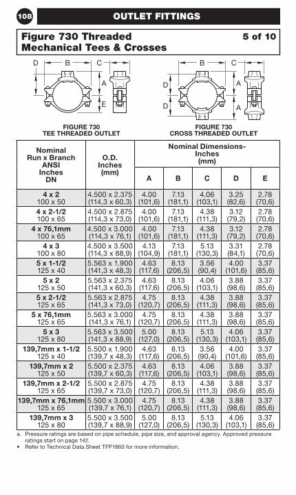
108 OUTLET FITTINGS
FIGURE 730 TEE THREADED OUTLET
FIGURE 730 CROSS THREADED OUTLET
Nominal Run x Branch
ANSI Inches
DN
O.D. Inches (mm)
Nominal Dimensions- Inches (mm)
A B C D E
4 x 2 100 x 50
4.500 x 2.375 (114,3 x 60,3)
4.00 (101,6)
7.13 (181,1)
4.06 (103,1)
3.25 (82,6)
2.78 (70,6)
4 x 2-1/2 100 x 65
4.500 x 2.875 (114,3 x 73,0)
4.00 (101,6)
7.13 (181,1)
4.38(111,3)
3.12 (79,2)
2.78 (70,6)
4 x 76,1mm 100 x 65
4.500 x 3.000 (114,3 x 76,1)
4.00 (101,6)
7.13 (181,1)
4.38 (111,3)
3.12 (79,2)
2.78 (70,6)
4 x 3 100 x 80
4.500 x 3.500 (114,3 x 88,9)
4.13 (104,9)
7.13 (181,1)
5.13 (130,3)
3.31 (84,1)
2.78 (70,6)
5 x 1-1/2 125 x 40
5.563 x 1.900 (141,3 x 48,3)
4.63 (117,6)
8.13 (206,5)
3.56 (90,4)
4.00 (101,6)
3.37 (85,6)
5 x 2 125 x 50
5.563 x 2.375 (141,3 x 60,3)
4.63 (117,6)
8.13 (206,5)
4.06 (103,1)
3.88 (98,6)
3.37 (85,6)
5 x 2-1/2 125 x 65
5.563 x 2.875 (141,3 x 73,0)
4.75 (120,7)
8.13 (206,5)
4.38 (111,3)
3.88 (98,6)
3.37 (85,6)
5 x 76,1mm 125 x 65
5.563 x 3.000 (141,3 x 76,1)
4.75 (120,7)
8.13 (206,5)
4.38 (111,3)
3.88 (98,6)
3.37 (85,6)
5 x 3 125 x 80
5.563 x 3.500 (141,3 x 88,9)
5.00 (127,0)
8.13 (206,5)
5.13 (130,3)
4.06 (103,1)
3.37 (85,6)
139,7mm x 1-1/2 125 x 40
5.500 x 1.900 (139,7 x 48,3)
4.63 (117,6)
8.13 (206,5)
3.56 (90,4)
4.00 (101,6)
3.37 (85,6)
139,7mm x 2 125 x 50
5.500 x 2.375 (139,7 x 60,3)
4.63 (117,6)
8.13 (206,5)
4.06 (103,1)
3.88 (98,6)
3.37 (85,6)
139,7mm x 2-1/2 125 x 65
5.500 x 2.875 (139,7 x 73,0)
4.75 (120,7)
8.13 (206,5)
4.38 (111,3)
3.88 (98,6)
3.37 (85,6)
139,7mm x 76,1mm 125 x 65
5.500 x 3.000 (139,7 x 76,1)
4.75 (120,7)
8.13 (206,5)
4.38 (111,3)
3.88 (98,6)
3.37 (85,6)
139,7mm x 3 125 x 80
5.500 x 3.500 (139,7 x 88,9)
5.00 (127,0)
8.13 (206,5)
5.13 (130,3)
4.06 (103,1)
3.37 (85,6)
a. Pressure ratings are based on pipe schedule, pipe size, and approval agency. Approved pressure ratings start on page 142.
• Refer to Technical Data Sheet TFP1860 for more information.
5 of 10Figure 730 Threaded Mechanical Tees & Crosses
CB
A
E
D B C
A
A
D
D
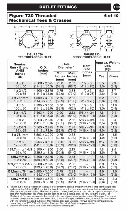
109OUTLET FITTINGS
FIGURE 730 TEE THREADED OUTLET
FIGURE 730 CROSS THREADED OUTLET
Nominal Run x Branch
ANSI Inches
DN
O.D. Inches (mm)
Hole Diameterb Boltc
Size Inches (mm)
Approx. Weight Lbs. (kg)
Min. Inches (mm)
Max. Inches (mm)
Tee Cross
4 x 2 100 x 50
4.500 x 2.375 (114,3 x 60,3)
2.50 (63,5)
2.63 (66,7)
1/2 x 3 (M12 x 76)
5.5 (2,5)
7.3 (3,3)
4 x 2-1/2 100 x 65
4.500 x 2.875 (114,3 x 73,0)
2.75 (69,9)
2.88 (73,0)
1/2 x 3 (M12 x 76)
6.2 (2,8)
8.7 (3,9)
4 x 76,1mm 100 x 65
4.500 x 3.000 (114,3 x 76,1)
2.75 (69,9)
2.88 (73,0)
— (M12 x 76)
6.2 (2,8)
8.7 (3,9)
4 x 3 100 x 80
4.500 x 3.500 (114,3 x 88,9)
3.50 (88,9)
3.63 (92,1)
1/2 x 3 (M12 x 76)
7.8 (3,5)
11.9 (5,4)
5 x 1-1/2 125 x 40
5.563 x 1.900 (141,3 x 48,3)
2.00 (50,8)
2.13 (54,0)
5/8 x 4-3/4 (M16 x 121)
7.8 (3,5)
9.4 (4,3)
5 x 2 125 x 50
5.563 x 2.375 (141,3 x 60,3)
2.50 (63,5)
2.63 (66,7)
5/8 x 4-3/4 (M16 x 121)
7.8 (3,5)
9.4 (4,3)
5 x 2-1/2 125 x 65
5.563 x 2.875 (141,3 x 73,0)
2.75 (69,9)
2.88 (73,0)
5/8 x 4-3/4 (M16 x 121)
8.9 (4,0)
11.5 (5,2)
5 x 76,1mm 125 x 65
5.563 x 3.000 (139,7 x 76,1)
2.75 (69,9)
2.88 (73,0)
— (M16 x 121)
8.9 (4,0)
11.5 (5,2)
5 x 3 125 x 80
5.563 x 3.500 (141,3 x 88,9)
3.50 (88,9)
3.63 (92,1)
5/8 x 4-3/4 (M16 x 121)
12.7 (5,8)
13.3 (6,0)
139,7mm x 1-1/2 125 x 40
5.500 x 1.900 (139,7 x 48,3)
2.00 (50,8)
2.13 (54,0)
— (M16 x 121)
7.8 (3,5)
9.4 (4,3)
139,7mm x 2 125 x 50
5.500 x 2.375 (139,7 x 60,3)
2.50 (63,5)
2.63 (66,7)
— (M16 x 121)
7.8 (3,5)
9.4 (4,3)
139,7mm x 2-1/2 125 x 65
5.500 x 2.875 (139,7 x 73,0)
2.75 (69,9)
2.88 (73,0)
— (M16 x 121)
8.9 (4,0)
11.5 (5,2)
139,7mm x 76,1mm 125 x 65
5.500 x 3.000 (139,7 x 76,1)
2.75 (69,9)
2.88 (73,0)
— (M16 x 121)
8.9 (4,0)
11.5 (5,2)
139,7mm x 3 125 x 80
5.500 x 3.500 (139,7 x 88,9)
3.50 (88,9)
3.63 (92,1)
— (M16 x 121)
12.7 (5,8)
13.3 (6,0)
b. Proper outlet hole preparation is required for effective sealing and performance. Inspect the pipe seal surface within 5/8 inch (15,9 mm) of the hole to ensure it is free from conditions that would adversely affect proper gasket sealing. Remove any sharp or rough edges from the hole or upper housing contact area that might affect assembly, proper seating of the locating collar or flow from the outlet. For Mechanical Crosses, ensure double outlet holes are aligned on opposite sides of the pipe. The use of threaded components other than steel pipe, such as dry type sprinklers, etc., may not be compatible with the female threaded outlets of Mechanical Tees and Crosses. Always confirm compatibility by contacting your TYCO Fire Protection Products Technical Services representative.
c. Gold color coded metric bolt sizes are available upon request.
6 of 10Figure 730 Threaded Mechanical Tees & Crosses
CB
A
E
D B C
A
A
D
D

110 OUTLET FITTINGS
Nominal Run x Branch
ANSI Inches
DN
O.D. Inches (mm)
Nominal Dimensions- Inches (mm)
A B C D E
6 x 1-1/4 150 x 32
6.625 x 1.660 (168,3 x 42,2)
5.13 (130,3)
9.25 (235,0)
3.56 (90,4)
4.25 (108,0)
3.90 (99,1)
6 x 1-1/2 150 x 40
6.625 x 1.900 (168,3 x 48,3)
5.13 (130,3)
9.25 (235,0)
3.56 (90,4)
4.04 (102,6)
3.90 (99,1)
6 x 2 150 x 50
6.625 x 2.375 (168,3 x 60,3)
5.13 (130,3)
9.25 (235,0)
4.06 (103,1)
4.31 (109,5)
3.90 (99,1)
6 x 2-1/2 150 x 65
6.625 x 2.875 (168,3 x 73,0)
5.13 (130,3)
9.25 (235,0)
4.38 (111,3)
4.18 (106,2)
3.90 (99,1)
6 x 76,1mm 150 x 65
6.625 x 3.000 (168,3 x 76,1)
5.13 (130,3)
9.25 (235,0)
4.38 (111,3)
4.18 (106,2)
3.90 (99,1)
6 x 3 150 x 80
6.625 x 3.500 (168,3 x 88,9)
5.50 (139,7)
9.25 (235,0)
5.13 (130,3)
4.37 (111,0)
3.90 (99,1)
6 x 4 150 x 100
6.625 x 4.500 (168,3 x 114,3)
5.38 (136,7)
9.25 (235,0)
6.13 (155,7)
4.56 (115,8)
3.90 (99,1)
165,1mm x 1-1/4 150 x 32
6.500 x 1.660 (165,1 x 42,2)
5.13 (130,3)
9.25 (235,0)
3.56 (90,4)
4.25 (108,0)
3.90 (99,1)
165,1mm x 1-1/2 150 x 40
6.500 x 1.900 (165,1 x 48,3)
5.13 (130,3)
9.25 (235,0)
3.56 (90,4)
4.04 (102,6)
3.90 (99,1)
165,1mm x 2 150 x 50
6.500 x 2.375 (165,1 x 60,3)
5.13 (130,3)
9.25 (235,0)
4.06 (103,1)
4.31 (109,5)
3.90 (99,1)
165,1mm x 2-1/2 150 x 65
6.500 x 2.875 (165,1 x 73,0)
5.13 (130,3)
9.25 (235,0)
4.38 (111,3)
4.18 (106,2)
3.90 (99,1)
165,1mm x 76,1mm 150 x 65
6.500 x 3.000 (165,1 x 76,1)
5.13 (130,3)
9.25 (235,0)
4.38 (111,3)
4.18 (106,2)
3.90 (99,1)
165,1mm x 3 150 x 80
6.500 x 3.500 (165,1 x 88,9)
5.50 (139,7)
9.25 (235,0)
5.13 (130,3)
4.37 (111,0)
3.90 (99,1)
8 x 2 200 x 50
8.625 x 2.375 (219,1 x 60,3)
6.25 (158,8)
12.50 (317,5)
4.06 (103,1)
5.50 (139,7)
4.90 (124,5)
a. Pressure ratings are based on pipe schedule, pipe size, and approval agency. Approved pressure ratings start on page 142.
• Refer to Technical Data Sheet TFP1860 for more information.
7 of 10Figure 730 Threaded Mechanical Tees & Crosses
FIGURE 730 TEE THREADED OUTLET
FIGURE 730 CROSS THREADED OUTLET
CB
A
E
D B C
A
A
D
D
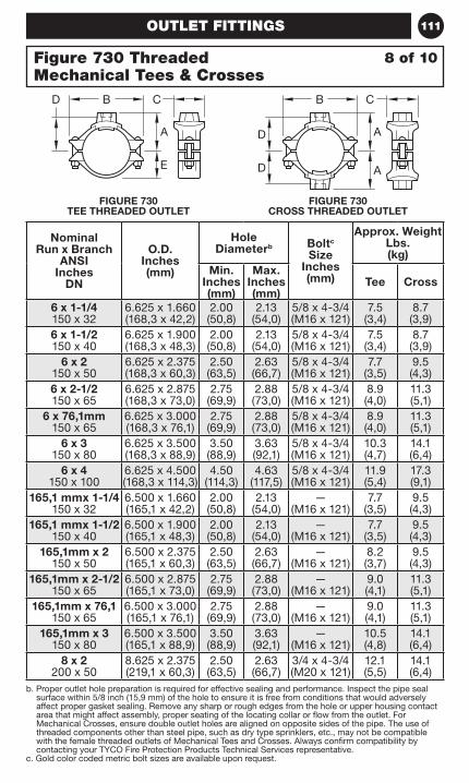
111OUTLET FITTINGS
FIGURE 730 TEE THREADED OUTLET
FIGURE 730 CROSS THREADED OUTLET
b. Proper outlet hole preparation is required for effective sealing and performance. Inspect the pipe seal surface within 5/8 inch (15,9 mm) of the hole to ensure it is free from conditions that would adversely affect proper gasket sealing. Remove any sharp or rough edges from the hole or upper housing contact area that might affect assembly, proper seating of the locating collar or flow from the outlet. For Mechanical Crosses, ensure double outlet holes are aligned on opposite sides of the pipe. The use of threaded components other than steel pipe, such as dry type sprinklers, etc., may not be compatible with the female threaded outlets of Mechanical Tees and Crosses. Always confirm compatibility by contacting your TYCO Fire Protection Products Technical Services representative.
c. Gold color coded metric bolt sizes are available upon request.
Nominal Run x Branch
ANSI Inches
DN
O.D. Inches (mm)
Hole Diameterb Boltc
Size Inches (mm)
Approx. Weight Lbs. (kg)
Min. Inches (mm)
Max. Inches (mm)
Tee Cross
6 x 1-1/4 150 x 32
6.625 x 1.660 (168,3 x 42,2)
2.00 (50,8)
2.13 (54,0)
5/8 x 4-3/4 (M16 x 121)
7.5 (3,4)
8.7 (3,9)
6 x 1-1/2 150 x 40
6.625 x 1.900 (168,3 x 48,3)
2.00 (50,8)
2.13 (54,0)
5/8 x 4-3/4(M16 x 121)
7.5 (3,4)
8.7 (3,9)
6 x 2 150 x 50
6.625 x 2.375 (168,3 x 60,3)
2.50 (63,5)
2.63 (66,7)
5/8 x 4-3/4 (M16 x 121)
7.7 (3,5)
9.5 (4,3)
6 x 2-1/2 150 x 65
6.625 x 2.875 (168,3 x 73,0)
2.75 (69,9)
2.88 (73,0)
5/8 x 4-3/4 (M16 x 121)
8.9 (4,0)
11.3 (5,1)
6 x 76,1mm 150 x 65
6.625 x 3.000 (168,3 x 76,1)
2.75 (69,9)
2.88 (73,0)
5/8 x 4-3/4 (M16 x 121)
8.9 (4,0)
11.3 (5,1)
6 x 3 150 x 80
6.625 x 3.500 (168,3 x 88,9)
3.50 (88,9)
3.63 (92,1)
5/8 x 4-3/4(M16 x 121)
10.3 (4,7)
14.1 (6,4)
6 x 4 150 x 100
6.625 x 4.500 (168,3 x 114,3)
4.50 (114,3)
4.63 (117,5)
5/8 x 4-3/4(M16 x 121)
11.9 (5,4)
17.3 (9,1)
165,1 mmx 1-1/4 150 x 32
6.500 x 1.660 (165,1 x 42,2)
2.00 (50,8)
2.13 (54,0)
— (M16 x 121)
7.7 (3,5)
9.5 (4,3)
165,1 mmx 1-1/2 150 x 40
6.500 x 1.900 (165,1 x 48,3)
2.00 (50,8)
2.13 (54,0)
— (M16 x 121)
7.7 (3,5)
9.5 (4,3)
165,1mm x 2 150 x 50
6.500 x 2.375 (165,1 x 60,3)
2.50 (63,5)
2.63 (66,7)
— (M16 x 121)
8.2 (3,7)
9.5 (4,3)
165,1mm x 2-1/2 150 x 65
6.500 x 2.875 (165,1 x 73,0)
2.75 (69,9)
2.88 (73,0)
— (M16 x 121)
9.0 (4,1)
11.3 (5,1)
165,1mm x 76,1 150 x 65
6.500 x 3.000 (165,1 x 76,1)
2.75 (69,9)
2.88 (73,0)
— (M16 x 121)
9.0 (4,1)
11.3 (5,1)
165,1mm x 3 150 x 80
6.500 x 3.500 (165,1 x 88,9)
3.50 (88,9)
3.63 (92,1)
— (M16 x 121)
10.5 (4,8)
14.1 (6,4)
8 x 2 200 x 50
8.625 x 2.375 (219,1 x 60,3)
2.50 (63,5)
2.63 (66,7)
3/4 x 4-3/4 (M20 x 121)
12.1 (5,5)
14.1 (6,4)
8 of 10Figure 730 Threaded Mechanical Tees & Crosses
CB
A
E
D B C
A
A
D
D
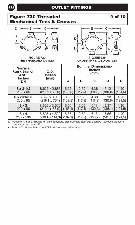
112 OUTLET FITTINGS
Nominal Run x Branch
ANSI Inches
DN
O.D. Inches (mm)
Nominal Dimensions- Inches (mm)
A B C D E
8 x 2-1/2 200 x 65
8.625 x 2.875 (219,1 x 73,0)
6.25 (158,8)
12.50 (317,5)
4.38 (111,3)
5.12 (130,0)
4.90 (124,5)
8 x 76,1mm 200 x 65
8.625 x 3.000 (219,1 x 76,1)
6.25 (158,8)
12.50 (317,5)
4.38 (111,3)
5.12 (130,0)
4.90 (124,5)
8 x 3 200 x 80
8.625 x 3.500 (219,1 x 88,9)
6.50 (165,1)
12.50 (317,5)
5.13 (130,3)
5.37 (136,4)
4.90 (124,5)
8 x 4 200 x 100
8.625 x 4.500 (219,1 x 114,3)
6.38 (162,1)
12.50 (317,5)
6.13 (155,7)
5.56 (141,2)
4.90 (124,5)
a. Pressure ratings are based on pipe schedule, pipe size, and approval agency. Approved pressure ratings start on page 142.
• Refer to Technical Data Sheet TFP1860 for more information.
9 of 10Figure 730 Threaded Mechanical Tees & Crosses
FIGURE 730 TEE THREADED OUTLET
FIGURE 730 CROSS THREADED OUTLET
CB
A
E
D B C
A
A
D
D
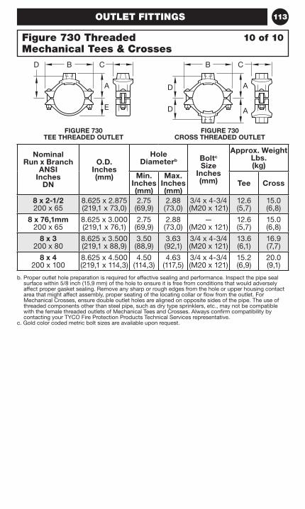
113OUTLET FITTINGS
b. Proper outlet hole preparation is required for effective sealing and performance. Inspect the pipe seal surface within 5/8 inch (15,9 mm) of the hole to ensure it is free from conditions that would adversely affect proper gasket sealing. Remove any sharp or rough edges from the hole or upper housing contact area that might affect assembly, proper seating of the locating collar or flow from the outlet. For Mechanical Crosses, ensure double outlet holes are aligned on opposite sides of the pipe. The use of threaded components other than steel pipe, such as dry type sprinklers, etc., may not be compatible with the female threaded outlets of Mechanical Tees and Crosses. Always confirm compatibility by contacting your TYCO Fire Protection Products Technical Services representative.
c. Gold color coded metric bolt sizes are available upon request.
Nominal Run x Branch
ANSI Inches
DN
O.D. Inches (mm)
Hole Diameterb Boltc
Size Inches (mm)
Approx. Weight Lbs. (kg)
Min. Inches (mm)
Max. Inches (mm)
Tee Cross
8 x 2-1/2 200 x 65
8.625 x 2.875 (219,1 x 73,0)
2.75 (69,9)
2.88 (73,0)
3/4 x 4-3/4 (M20 x 121)
12.6 (5,7)
15.0 (6,8)
8 x 76,1mm 200 x 65
8.625 x 3.000 (219,1 x 76,1)
2.75 (69,9)
2.88 (73,0)
— (M20 x 121)
12.6 (5,7)
15.0 (6,8)
8 x 3 200 x 80
8.625 x 3.500 (219,1 x 88,9)
3.50 (88,9)
3.63 (92,1)
3/4 x 4-3/4 (M20 x 121)
13.6 (6,1)
16.9 (7,7)
8 x 4 200 x 100
8.625 x 4.500 (219,1 x 114,3)
4.50 (114,3)
4.63 (117,5)
3/4 x 4-3/4 (M20 x 121)
15.2 (6,9)
20.0 (9,1)
10 of 10Figure 730 Threaded Mechanical Tees & Crosses
FIGURE 730 TEE THREADED OUTLET
FIGURE 730 CROSS THREADED OUTLET
CB
A
E
D B C
A
A
D
D

114 OUTLET FITTINGS
Nominal Run x Branch
ANSI Inches
DN
O.D. Inches (mm)
Nominal Dimensions- Inches (mm)
A B C E
2 x 1-1/4 50 x 32
2.375 x 1.660 (60,3 x 42,2)
2.78 (70,6)
4.88 (124,0)
3.32 (84,3)
1.59 (40,4)
2 x 1-1/2 50 x 40
2.375 x 1.900 (60,3 x 48,3)
2.62 (66,5)
4.88 (124,0)
3.32 (84,3)
1.59 (40,4)
2-1/2 x 1-1/4 65 x 32
2.875 x 1.660 (73,0 x 42,2)
3.00 (76,2)
5.25 (133,4)
3.56 (90,4)
1.81 (46,0)
2-1/2 x 1-1/2 65 x 40
2.875 x 1.900 (73,0 x 48,3)
3.07 (78,0)
5.25 (133,4)
3.59 (91,2)
1.81 (46,0)
2-1/2 x 2 65 x 50
2.875 x 2.375 (73,0 x 60,3)
3.19 (81,0)
5.25 (133,4)
4.00 (101,6)
1.81 (46,0)
76,1mm x 1 65 x 32
3.000 x 1.315 (76,1 x 33,7)
2.94 (74,5)
5.62 (142,7)
3.07 (78,0)
1.87 (47,5)
76,1mm x 1-1/4 65 x 32
3.000 x 1.660 (76,1 x 42,4)
3.06 (77,7)
5.62 (142,7)
3.56 (90,4)
1.87 (47,5)
76,1mm x 1-1/2 65 x 40
3.000 x 1.900 (76,1 x 48,3)
3.13 (79,5)
5.62 (142,7)
3.56 (90,4)
1.87 (47,5)
76,1mm x 2 65 x 50
3.000 x 2.375 (76,1 x 60,3)
3.25 (82,6)
5.62 (142,7)
4.00 (101,6)
1.87 (47,5)
3 x 1-1/4 80 x 32
3.500 x 1.660 (88,9 x 42,2)
3.34 (84,8)
6.13 (155,7)
3.32 (84,3)
2.21 (56,1)
3 x 1-1/2 80 x 40
3.500 x 1.900 (88,9 x 48,3)
3.38 (85,9)
6.13 (155,7)
3.56 (90,4)
2.21 (56,1)
3 x 2 80 x 50
3.500 x 2.375 (88,9 x 60,3)
3.50 (88,9)
6.13 (155,7)
4.09 (103,9)
2.21 (56,1)
4 x 1-1/4 100 x 32
4.500 x 1.660 (114,3 x 42,2)
3.92 (99,6)
7.13 (181,1)
3.32 (84,3)
2.78 (70,6)
4 x 1-1/2 100 x 40
4.500 x 1.900 (114,3 x 48,3)
4.00 (101,6)
7.13 (181,1)
3.56 (90,4)
2.78 (70,6)
• Pressure ratings are based on pipe schedule, pipe size, and approval agency. Approved pressure ratings start on page 152.
• Refer to Technical Data Sheet TFP1860 for more information.
1 of 8Figure 730 Grooved Mechanical Tees & Crosses
FIGURE 730 TEE GROOVED OUTLET
FIGURE 730 CROSS GROOVED OUTLET
CB
A
E
B C
A
A
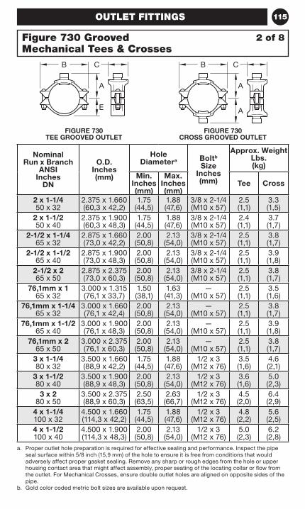
115OUTLET FITTINGS
a. Proper outlet hole preparation is required for effective sealing and performance. Inspect the pipe seal surface within 5/8 inch (15,9 mm) of the hole to ensure it is free from conditions that would adversely affect proper gasket sealing. Remove any sharp or rough edges from the hole or upper housing contact area that might affect assembly, proper seating of the locating collar or flow from the outlet. For Mechanical Crosses, ensure double outlet holes are aligned on opposite sides of the pipe.
b. Gold color coded metric bolt sizes are available upon request.
Nominal Run x Branch
ANSI Inches
DN
O.D. Inches (mm)
Hole Diametera Boltb
Size Inches (mm)
Approx. Weight Lbs. (kg)
Min. Inches (mm)
Max. Inches (mm)
Tee Cross
2 x 1-1/4 50 x 32
2.375 x 1.660 (60,3 x 42,2)
1.75 (44,5)
1.88 (47,6)
3/8 x 2-1/4 (M10 x 57)
2.5 (1,1)
3.3 (1,5)
2 x 1-1/2 50 x 40
2.375 x 1.900 (60,3 x 48,3)
1.75 (44,5)
1.88 (47,6)
3/8 x 2-1/4 (M10 x 57)
2.4 (1,1)
3.7 (1,7)
2-1/2 x 1-1/4 65 x 32
2.875 x 1.660 (73,0 x 42,2)
2.00 (50,8)
2.13 (54,0)
3/8 x 2-1/4 (M10 x 57)
2.5 (1,1)
3.8 (1,7)
2-1/2 x 1-1/2 65 x 40
2.875 x 1.900 (73,0 x 48,3)
2.00 (50,8)
2.13 (54,0)
3/8 x 2-1/4 (M10 x 57)
2.5 (1,1)
3.9 (1,8)
2-1/2 x 2 65 x 50
2.875 x 2.375 (73,0 x 60,3)
2.00 (50,8)
2.13 (54,0)
3/8 x 2-1/4 (M10 x 57)
2.5 (1,1)
3.8 (1,7)
76,1mm x 1 65 x 32
3.000 x 1.315 (76,1 x 33,7)
1.50 (38,1)
1.63 (41,3)
— (M10 x 57)
2.5 (1,1)
3.5(1,6)
76,1mm x 1-1/4 65 x 32
3.000 x 1.660 (76,1 x 42,4)
2.00 (50,8)
2.13 (54,0)
— (M10 x 57)
2.5 (1,1)
3.8 (1,7)
76,1mm x 1-1/2 65 x 40
3.000 x 1.900 (76,1 x 48,3)
2.00 (50,8)
2.13 (54,0)
— (M10 x 57)
2.5 (1,1)
3.9 (1,8)
76,1mm x 2 65 x 50
3.000 x 2.375 (76,1 x 60,3)
2.00 (50,8)
2.13 (54,0)
— (M10 x 57)
2.5 (1,1)
3.8 (1,7)
3 x 1-1/4 80 x 32
3.500 x 1.660 (88,9 x 42,2)
1.75 (44,5)
1.88 (47,6)
1/2 x 3 (M12 x 76)
3.5 (1,6)
4.6 (2,1)
3 x 1-1/2 80 x 40
3.500 x 1.900 (88,9 x 48,3)
2.00 (50,8)
2.13 (54,0)
1/2 x 3 (M12 x 76)
3.6 (1,6)
5.0 (2,3)
3 x 2 80 x 50
3.500 x 2.375 (88,9 x 60,3)
2.50 (63,5)
2.63 (66,7)
1/2 x 3 (M12 x 76)
4.5 (2,0)
6.4 (2,9)
4 x 1-1/4 100 x 32
4.500 x 1.660 (114,3 x 42,2)
1.75 (44,5)
1.88 (47,6)
1/2 x 3 (M12 x 76)
4.8 (2,2)
5.6 (2,5)
4 x 1-1/2 100 x 40
4.500 x 1.900 (114,3 x 48,3)
2.00 (50,8)
2.13 (54,0)
1/2 x 3 (M12 x 76)
5.0 (2,3)
6.2 (2,8)
2 of 8Figure 730 Grooved Mechanical Tees & Crosses
FIGURE 730 TEE GROOVED OUTLET
FIGURE 730 CROSS GROOVED OUTLET
CB
A
E
B C
A
A
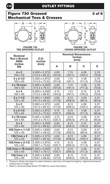
116 OUTLET FITTINGS
Nominal Run x Branch
ANSI Inches
DN
O.D. Inches (mm)
Nominal Dimensions- Inches (mm)
A B C E
4 x 2 100 x 50
4.500 x 2.375 (114,3 x 60,3)
4.00 (101,6)
7.13 (181,1)
4.06 (103,1)
2.78 (70,6)
4 x 2-1/2 100 x 65
4.500 x 2.875 (114,3 x 73,0)
4.00 (101,6)
7.13 (181,1)
4.38 (111,3)
2.78 (70,6)
4 x 76,1mm 100 x 65
4.500 x 3.000 (114,3 x 76,1)
4.00 (101,6)
7.13 (181,1)
4.38 (111,3)
2.78 (70,6)
4 x 3 100 x 80
4.500 x 3.500 (114,3 x 88,9)
4.13 (104,9)
7.13 (181,1)
5.13 (130,3)
2.78 (70,6)
5 x 1-1/2 125 x 40
5.563 x 1.900 (141,3 x 48,3)
4.63 (117,6)
8.13 (206,5)
3.56 (90,4)
3.37 (85,6)
5 x 2 125 x 50
5.563 x 2.375 (141,3 x 60,3)
4.63 (117,6)
8.13 (206,5)
4.06 (103,1)
3.37 (85,6)
5 x 2-1/2 125 x 65
5.563 x 2.875 (141,3 x 73,0)
4.75 (120,7)
8.13 (206,5)
4.38 (111,3)
3.37 (85,6)
5 x 76,1mm 125 x 65
5.563 x 3.000 (141,3 x 76,1)
4.75 (120,7)
8.13 (206,5)
4.38 (111,3)
3.37 (85,6)
5 x 3 125 x 80
5.563 x 3.500 (141,3 x 88,9)
5.00 (127,0)
8.13 (206,5)
5.13 (130,3)
3.37 (85,6)
139,7mm x 1-1/2 125 x 40
5.500 x 1.900 (139,7 x 48,3)
4.63 (117,6)
8.13 (206,5)
3.56 (90,4)
3.37 (85,6)
139,7mm x 2 125 x 50
5.500 x 2.375 (139,7 x 60,3)
4.63 (117,6)
8.13 (206,5)
4.06 (103,1)
3.37 (85,6)
139,7mm x 2-1/2 125 x 65
5.500 x 2.875 (139,7 x 73,0)
4.75 (120,7)
8.13 (206,5)
4.38 (111,3)
3.37 (85,6)
139,7mm x 76,1mm 125 x 65
5.500 x 3.000 (139,7 x 76,1)
4.75 (120,7)
8.13 (206,5)
4.38 (111,3)
3.37 (85,6)
139,7mm x 3 125 x 80
5.500 x 3.500 (139,7 x 88,9)
5.00 (127,0)
8.13 (206,5)
5.13 (130,3)
3.37 (85,6)
• Pressure ratings are based on pipe schedule, pipe size, and approval agency. Approved pressure ratings start on page 152.
• Refer to Technical Data Sheet TFP1860 for more information.
FIGURE 730 TEE GROOVED OUTLET
FIGURE 730 CROSS GROOVED OUTLET
3 of 8Figure 730 Grooved Mechanical Tees & Crosses
CB
A
E
B C
A
A
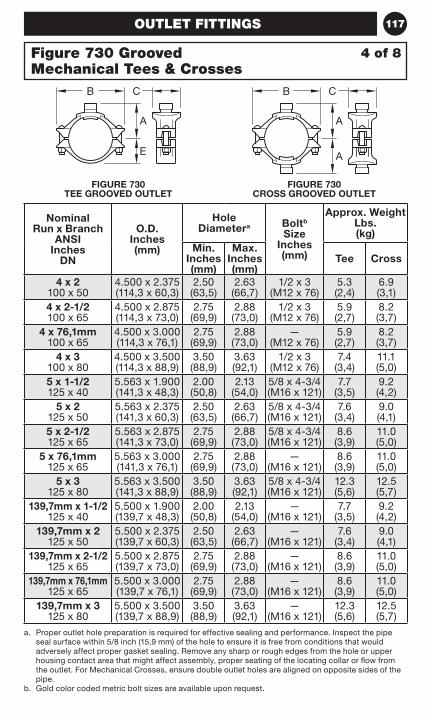
117
Figure 730 Grooved Mechanical Tees & Crosses
OUTLET FITTINGS
a. Proper outlet hole preparation is required for effective sealing and performance. Inspect the pipe seal surface within 5/8 inch (15,9 mm) of the hole to ensure it is free from conditions that would adversely affect proper gasket sealing. Remove any sharp or rough edges from the hole or upper housing contact area that might affect assembly, proper seating of the locating collar or flow from the outlet. For Mechanical Crosses, ensure double outlet holes are aligned on opposite sides of the pipe.
b. Gold color coded metric bolt sizes are available upon request.
Nominal Run x Branch
ANSI Inches
DN
O.D. Inches (mm)
Hole Diametera Boltb
Size Inches (mm)
Approx. Weight Lbs. (kg)
Min. Inches (mm)
Max. Inches (mm)
Tee Cross
4 x 2 100 x 50
4.500 x 2.375 (114,3 x 60,3)
2.50 (63,5)
2.63 (66,7)
1/2 x 3 (M12 x 76)
5.3 (2,4)
6.9(3,1)
4 x 2-1/2 100 x 65
4.500 x 2.875 (114,3 x 73,0)
2.75 (69,9)
2.88 (73,0)
1/2 x 3 (M12 x 76)
5.9 (2,7)
8.2 (3,7)
4 x 76,1mm 100 x 65
4.500 x 3.000 (114,3 x 76,1)
2.75 (69,9)
2.88 (73,0)
— (M12 x 76)
5.9 (2,7)
8.2 (3,7)
4 x 3 100 x 80
4.500 x 3.500 (114,3 x 88,9)
3.50 (88,9)
3.63 (92,1)
1/2 x 3 (M12 x 76)
7.4 (3,4)
11.1 (5,0)
5 x 1-1/2 125 x 40
5.563 x 1.900 (141,3 x 48,3)
2.00 (50,8)
2.13 (54,0)
5/8 x 4-3/4 (M16 x 121)
7.7 (3,5)
9.2 (4,2)
5 x 2 125 x 50
5.563 x 2.375 (141,3 x 60,3)
2.50 (63,5)
2.63 (66,7)
5/8 x 4-3/4 (M16 x 121)
7.6 (3,4)
9.0 (4,1)
5 x 2-1/2 125 x 65
5.563 x 2.875 (141,3 x 73,0)
2.75 (69,9)
2.88 (73,0)
5/8 x 4-3/4 (M16 x 121)
8.6 (3,9)
11.0 (5,0)
5 x 76,1mm 125 x 65
5.563 x 3.000 (141,3 x 76,1)
2.75 (69,9)
2.88 (73,0)
— (M16 x 121)
8.6 (3,9)
11.0 (5,0)
5 x 3 125 x 80
5.563 x 3.500 (141,3 x 88,9)
3.50 (88,9)
3.63 (92,1)
5/8 x 4-3/4(M16 x 121)
12.3 (5,6)
12.5(5,7)
139,7mm x 1-1/2 125 x 40
5.500 x 1.900 (139,7 x 48,3)
2.00 (50,8)
2.13 (54,0)
— (M16 x 121)
7.7 (3,5)
9.2 (4,2)
139,7mm x 2 125 x 50
5.500 x 2.375 (139,7 x 60,3)
2.50 (63,5)
2.63 (66,7)
— (M16 x 121)
7.6 (3,4)
9.0 (4,1)
139,7mm x 2-1/2 125 x 65
5.500 x 2.875 (139,7 x 73,0)
2.75 (69,9)
2.88 (73,0)
— (M16 x 121)
8.6 (3,9)
11.0 (5,0)
139,7mm x 76,1mm 125 x 65
5.500 x 3.000 (139,7 x 76,1)
2.75 (69,9)
2.88 (73,0)
— (M16 x 121)
8.6 (3,9)
11.0 (5,0)
139,7mm x 3 125 x 80
5.500 x 3.500 (139,7 x 88,9)
3.50 (88,9)
3.63 (92,1)
— (M16 x 121)
12.3 (5,6)
12.5 (5,7)
FIGURE 730 TEE GROOVED OUTLET
FIGURE 730 CROSS GROOVED OUTLET
CB
A
E
B C
A
A
4 of 8

118 OUTLET FITTINGS
Nominal Run x Branch
ANSI Inches
DN
O.D. Inches (mm)
Nominal Dimensions- Inches (mm)
A B C E
6 x 1-1/4 150 x 32
6.625 x 1.660 (168,3 x 42,2)
5.13 (130,3)
9.25 (235,0)
3.56 (90.4)
3.90 (99,1)
6 x 1-1/2 150 x 40
6.625 x 1.900 (168,3 x 48,3)
5.13 (130,3)
9.25 (235,0)
3.56 (90,4)
3.90 (99,1)
6 x 2 150 x 50
6.625 x 2.375 (168,3 x 60,3)
5.13 (130,3)
9.25 (235,0)
4.06 (103,1)
3.90 (99,1)
6 x 2-1/2 150 x 65
6.625 x 2.875 (168,3 x 73,0)
5.13 (130,3)
9.25 (235,0)
4.38 (111,3)
3.90 (99,1)
6 x 76,1mm 150 x 65
6.625 x 3.000 (168,3 x 76,1)
5.13 (130,3)
9.25 (235,0)
4.38 (111,3)
3.90 (99,1)
6 x 3 150 x 80
6.625 x 3.500 (168,3 x 88,9)
5.50 (139,7)
9.25 (235,0)
5.13 (130,3)
3.90 (99,1)
6 x 4 150 x 100
6.625 x 4.500 (168,3 x 114,3)
5.38 (136,7)
9.25 (235,0)
6.13 (155,7)
3.90 (99,1)
165,1mm x 1-1/4150 x 32
6.500 x 1.660 (165,1 x 42,2)
5.13 (130,3)
9.25 (235,0)
3.56 (90,4)
3.90 (99,1)
165,1mm x 1-1/2150 x 40
6.500 x 1.900 (165,1 x 48,3)
5.13 (130,3)
9.25 (235,0)
3.56 (90,4)
3.90 (99,1)
165,1mm x 2150 x 50
6.500 x 2.375 (165,1 x 60,3)
5.13 (130,3)
9.25 (235,0)
4.06 (103,1)
3.90 (99,1)
165,1mm x 2-1/2150 x 65
6.500 x 2.875 (165,1 x 73,0)
5.13 (130,3)
9.25 (235,0)
4.38 (111,3)
3.90 (99,1)
165,1mm x 76,1mm150 x 65
6.500 x 3.000 (165,1 x 76,1)
5.13 (130,3)
9.25 (235,0)
4.38 (111,3)
3.90 (99,1)
165,1mm x 3150 x 80
6.500 x 3.500 (165,1 x 88,9)
5.50 (139,7)
9.25 (235,0)
5.13 (130,3)
3.90 (99,1)
165,mm x 4150 x 100
6.500 x 4.500 (165,1 x 114,1)
5.38 (136,7)
9.25 (235,0)
6.13 (155,7)
3.90 (99,1)
• Pressure ratings are based on pipe schedule, pipe size, and approval agency. Approved pressure ratings start on page 152.
• Refer to Technical Data Sheet TFP1860 for more information.
5 of 8Figure 730 Grooved Mechanical Tees & Crosses
FIGURE 730 TEE GROOVED OUTLET
FIGURE 730 CROSS GROOVED OUTLET
CB
A
E
B C
A
A
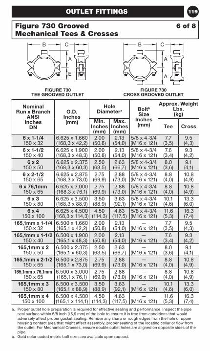
119OUTLET FITTINGS
a. Proper outlet hole preparation is required for effective sealing and performance. Inspect the pipe seal surface within 5/8 inch (15,9 mm) of the hole to ensure it is free from conditions that would adversely affect proper gasket sealing. Remove any sharp or rough edges from the hole or upper housing contact area that might affect assembly, proper seating of the locating collar or flow from the outlet. For Mechanical Crosses, ensure double outlet holes are aligned on opposite sides of the pipe.
b. Gold color coded metric bolt sizes are available upon request.
Nominal Run x Branch
ANSI Inches
DN
O.D. Inches (mm)
Hole Diametera Boltb
Size Inches (mm)
Approx. Weight Lbs. (kg)
Min. Inches (mm)
Max. Inches (mm)
Tee Cross
6 x 1-1/4 150 x 32
6.625 x 1.660 (168,3 x 42,2)
2.00 (50,8)
2.13 (54,0)
5/8 x 4-3/4 (M16 x 121)
7.7 (3,5)
9.5 (4,3)
6 x 1-1/2 150 x 40
6.625 x 1.900 (168,3 x 48,3)
2.00 (50,8)
2.13 (54,0)
5/8 x 4-3/4 (M16 x 121)
7.6 (3,4)
9.3 (4,2)
6 x 2 150 x 50
6.625 x 2.375 (168,3 x 60,3)
2.50 (63,5)
2.63 (66,7)
5/8 x 4-3/4 (M16 x 121)
8.0 (3,6)
9.1 (4,1)
6 x 2-1/2 150 x 65
6.625 x 2.875 (168,3 x 73,0)
2.75 (69,9)
2.88 (73,0)
5/8 x 4-3/4 (M16 x 121)
8.8 (4,0)
10.8 (4,9)
6 x 76,1mm 150 x 65
6.625 x 3.000 (168,3 x 76,1)
2.75 (69,9)
2.88 (73,0)
5/8 x 4-3/4 (M16 x 121)
8.8 (4,0)
10.8 (4,9)
6 x 3 150 x 80
6.625 x 3.500 (168,3 x 88,9)
3.50 (88,9)
3.63 (92,1)
5/8 x 4-3/4 (M16 x 121)
10.1 (4,6)
13.3 (6,0)
6 x 4 150 x 100
6.625 x 4.500 (168,3 x 114,3)
4.50 (114,3)
4.63 (117,5)
5/8 x 4-3/4 (M16 x 121)
11.6 (5,3)
16.3 (7,4)
165,1mm x 1-1/4150 x 32
6.500 x 1.660 (165,1 x 42,2)
2.00 (50,8)
2.13 (54,0)
— (M16 x 121)
7.7 (3,5)
9.5 (4,3)
165,1mm x 1-1/2150 x 40
6.500 x 1.900 (165,1 x 48,3)
2.00 (50,8)
2.13 (54,0)
— (M16 x 121)
7.6 (3,4)
9.3 (4,2)
165,1mm x 2150 x 50
6.500 x 2.375 (165,1 x 60,3)
2.50 (63,5)
2.63 (66,7)
— (M16 x 121)
8.0 (3,6)
9.1 (4,1)
165,1mm x 2-1/2150 x 65
6.500 x 2.875 (165,1 x 73,0)
2.75 (69,9)
2.88 (73,0)
— (M16 x 121)
8.8 (4,0)
10.8 (4,9)
165,1mm x 76,1mm150 x 65
6.500 x 3.000 (165,1 x 76,1)
2.75 (69,9)
2.88 (73,0)
— (M16 x 121)
8.8 (4,0)
10.8 (4,9)
165,1mm x 3150 x 80
6.500 x 3.500 (165,1 x 88,9)
3.50 (88,9)
3.63 (92,1)
— (M16 x 121)
10.1 (4,6)
13.3 (6,0)
165,1mm x 4150 x 100
6.500 x 4.500 (165,1 x 114,1)
4.50 (114,3)
4.63 (117,5)
— (M16 x 121)
11.6 (5,3)
16.3 (7,4)
6 of 8Figure 730 Grooved Mechanical Tees & Crosses
FIGURE 730 TEE GROOVED OUTLET
FIGURE 730 CROSS GROOVED OUTLET
CB
A
E
B C
A
A
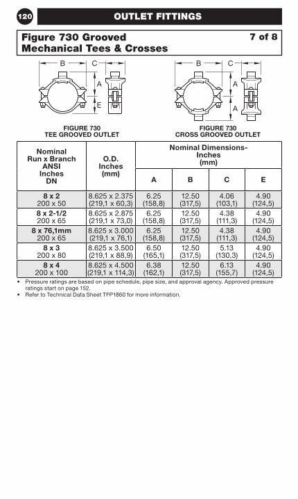
120 OUTLET FITTINGS
Nominal Run x Branch
ANSI Inches
DN
O.D. Inches (mm)
Nominal Dimensions- Inches (mm)
A B C E
8 x 2 200 x 50
8.625 x 2.375 (219,1 x 60,3)
6.25 (158,8)
12.50 (317,5)
4.06 (103,1)
4.90 (124,5)
8 x 2-1/2 200 x 65
8.625 x 2.875 (219,1 x 73,0)
6.25 (158,8)
12.50 (317,5)
4.38 (111,3)
4.90 (124,5)
8 x 76,1mm 200 x 65
8.625 x 3.000 (219,1 x 76,1)
6.25 (158,8)
12.50 (317,5)
4.38 (111,3)
4.90 (124,5)
8 x 3 200 x 80
8.625 x 3.500 (219,1 x 88,9)
6.50 (165,1)
12.50 (317,5)
5.13 (130,3)
4.90 (124,5)
8 x 4 200 x 100
8.625 x 4.500 (219,1 x 114,3)
6.38 (162,1)
12.50 (317,5)
6.13 (155,7)
4.90 (124,5)
• Pressure ratings are based on pipe schedule, pipe size, and approval agency. Approved pressure ratings start on page 152.
• Refer to Technical Data Sheet TFP1860 for more information.
7 of 8Figure 730 Grooved Mechanical Tees & Crosses
FIGURE 730 TEE GROOVED OUTLET
FIGURE 730 CROSS GROOVED OUTLET
CB
A
E
B C
A
A
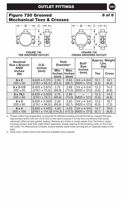
121
Figure 730 Grooved Mechanical Tees & Crosses
OUTLET FITTINGS
a. Proper outlet hole preparation is required for effective sealing and performance. Inspect the pipe seal surface within 5/8 inch (15,9 mm) of the hole to ensure it is free from conditions that would adversely affect proper gasket sealing. Remove any sharp or rough edges from the hole or upper housing contact area that might affect assembly, proper seating of the locating collar or flow from the outlet. For Mechanical Crosses, ensure double outlet holes are aligned on opposite sides of the pipe.
b. Gold color coded metric bolt sizes are available upon request.
Nominal Run x Branch
ANSI Inches
DN
O.D. Inches (mm)
Hole Diametera Boltb
Size Inches (mm)
Approx. Weight Lbs. (kg)
Min. Inches (mm)
Max. Inches (mm)
Tee Cross
8 x 2 200 x 50
8.625 x 2.375 (219,1 x 60,3)
2.50 (63,5)
2.63 (66,7)
3/4 x 4-3/4 (M20 x 121)
12.1 (5,5)
14.1 (6,4)
8 x 2-1/2 200 x 65
8.625 x 2.875 (219,1 x 73,0)
2.75 (69,9)
2.88 (73,0)
3/4 x 4-3/4 (M20 x 121)
12.3 (5,6)
14.5 (6,6)
8 x 76,1 200 x 65
8.625 x 3.000 (219,1 x 76,1)
2.75 (69,9)
2.88 (73,0)
— (M20 x 121)
12.3 (5,6)
14.5 (6,6)
8 x 3 200 x 80
8.625 x 3.500 (219,1 x 88,9)
3.50 (88,9)
3.63 (92,1)
3/4 x 4-3/4 (M20 x 121)
13.2 (6,0)
16.1 (7,3)
8 x 4 200 x 100
8.625 x 4.500 (219,1 x 114,3)
4.50 (114,3)
4.63 (117,5)
3/4 x 4-3/4 (M20 x 121)
14.7 (6,7)
19.0 (8,6)
FIGURE 730 TEE GROOVED OUTLET
FIGURE 730 CROSS GROOVED OUTLET
8 of 8
CB
A
E
B C
A
A
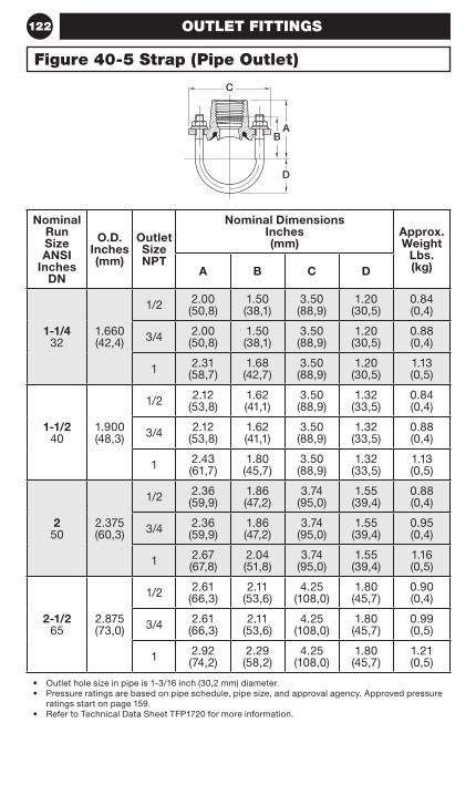
122 OUTLET FITTINGS
Nominal Run Size ANSI
Inches DN
O.D. Inches (mm)
Outlet Size NPT
Nominal Dimensions Inches (mm)
Approx. Weight
Lbs. (kg)A B C D
1-1/4 32
1.660 (42,4)
1/2 2.00 (50,8)
1.50 (38,1)
3.50 (88,9)
1.20 (30,5)
0.84 (0,4)
3/4 2.00 (50,8)
1.50 (38,1)
3.50 (88,9)
1.20 (30,5)
0.88 (0,4)
1 2.31 (58,7)
1.68 (42,7)
3.50 (88,9)
1.20 (30,5)
1.13 (0,5)
1-1/2 40
1.900 (48,3)
1/2 2.12 (53,8)
1.62 (41,1)
3.50 (88,9)
1.32 (33,5)
0.84 (0,4)
3/4 2.12 (53,8)
1.62 (41,1)
3.50 (88,9)
1.32 (33,5)
0.88 (0,4)
1 2.43 (61,7)
1.80 (45,7)
3.50 (88,9)
1.32 (33,5)
1.13 (0,5)
2 50
2.375 (60,3)
1/2 2.36 (59,9)
1.86 (47,2)
3.74 (95,0)
1.55 (39,4)
0.88 (0,4)
3/4 2.36 (59,9)
1.86 (47,2)
3.74 (95,0)
1.55 (39,4)
0.95 (0,4)
1 2.67 (67,8)
2.04 (51,8)
3.74 (95,0)
1.55 (39,4)
1.16 (0,5)
2-1/2 65
2.875 (73,0)
1/2 2.61 (66,3)
2.11 (53,6)
4.25 (108,0)
1.80 (45,7)
0.90 (0,4)
3/4 2.61 (66,3)
2.11 (53,6)
4.25 (108,0)
1.80 (45,7)
0.99 (0,5)
1 2.92 (74,2)
2.29 (58,2)
4.25 (108,0)
1.80 (45,7)
1.21 (0,5)
• Outlet hole size in pipe is 1-3/16 inch (30,2 mm) diameter.• Pressure ratings are based on pipe schedule, pipe size, and approval agency. Approved pressure
ratings start on page 159.• Refer to Technical Data Sheet TFP1720 for more information.
Figure 40-5 Strap (Pipe Outlet)
A
C
B
D
123VALVES
Valves
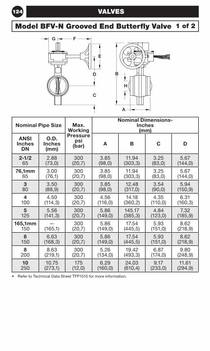
124 VALVES
Nominal Pipe Size Max. Working Pressure
psi (bar)
Nominal Dimensions- Inches (mm)
ANSI Inches
DN
O.D. Inches (mm)
A B C D
2-1/2 65
2.88 (73,0)
300 (20,7)
3.85 (98,0)
11.94 (303,3)
3.25 (83,0)
5.67 (144,0)
76,1mm 65
3.00 (76,1)
300 (20,7)
3.85 (98,0)
11.94 (303,3)
3.25 (83,0)
5.67 (144,0)
3 80
3.50 (88,9)
300 (20,7)
3.85 (98,0)
12.48 (317,0)
3.54 (90,0)
5.94 (150,9)
4 100
4.50 (114,3)
300 (20,7)
4.56 (116,0)
14.18 (360,2)
4.35 (110,0)
6.31 (160,3)
5 125
5.56 (141,3)
300 (20,7)
5.86 (149,0)
145.17 (385,3)
4.84 (123,0)
7.32 (185,9)
165,1mm 150
— (165,1)
300 (20,7)
5.86 (149,0)
17.54 (445,5)
5.93 (151,0)
8.62 (218,9)
6 150
6.63 (168,3)
300 (20,7)
5.86 (149,0)
17.54 (445,5)
5.93 (151,0)
8.62 (218,9)
8 200
8.63 (219,1)
300 (20,7)
5.26 (134,0)
19.42 (493,3)
6.87 (174,0)
9.80 (248,9)
10 250
10.75 (273,1)
175 (12,0)
6.29 (160,0)
24.03 (610,4)
9.17 (233,0)
11.61 (294,9)
• Refer to Technical Data Sheet TFP1510 for more information.
1 of 2Model BFV-N Grooved End Butterfly Valve
FG
E
BD
C
A
H
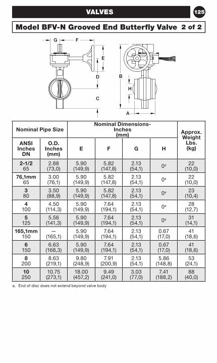
125VALVES
Nominal Pipe SizeNominal Dimensions-
Inches (mm) Approx.
Weight Lbs. (kg)
ANSI Inches
DN
O.D. Inches (mm)
E F G H
2-1/2 65
2.88 (73,0)
5.90 (149,9)
5.82 (147,8)
2.13 (54,1) 0a 22
(10,0)
76,1mm 65
3.00 (76,1)
5.90 (149,9)
5.82 (147,8)
2.13 (54,1) 0a 22
(10,0)
3 80
3.50 (88,9)
5.90 (149,9)
5.82 (147,8)
2.13 (54,1) 0a 23
(10,4)
4 100
4.50 (114,3)
5.90 (149,9)
7.64 (194,1)
2.13 (54,1) 0a 28
(12,7)
5 125
5.56 (141,3)
5.90 (149,9)
7.64 (194,1)
2.13 (54,1) 0a 31
(14,1)
165,1mm 150
— (165,1)
5.90 (149,9)
7.64 (194,1)
2.13 (54,1)
0.67 (17,0)
41 (18,6)
6 150
6.63 (168,3)
5.90 (149,9)
7.64 (194,1)
2.13 (54,1)
0.67 (17,0)
41 (18,6)
8 200
8.63 (219,1)
9.80 (248,9)
7.91 (200,9)
2.13 (54,1)
5.86 (148,8)
53 (24,1)
10 250
10.75 (273,1)
18.00 (457,2)
9.49 (241,0)
3.03 (77,0)
7.41 (188,2)
88 (40,0)
a. End of disc does not extend beyond valve body
Model BFV-N Grooved End Butterfly Valve 2 of 2
FG
E
BD
C
A
H
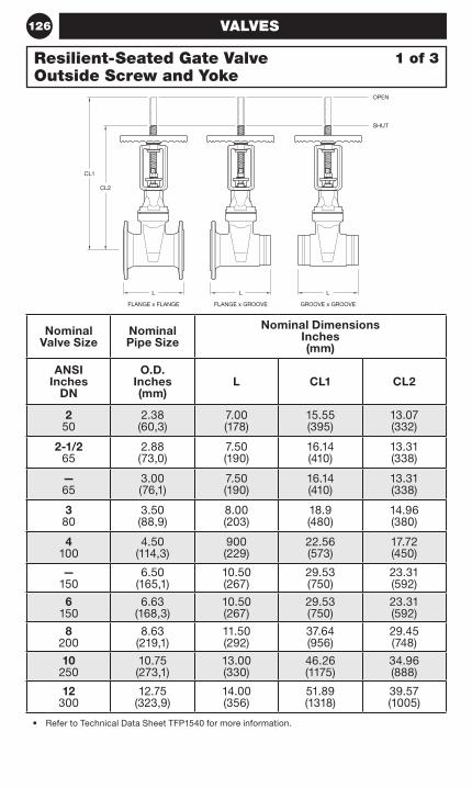
126 VALVES
Nominal Valve Size
Nominal Pipe Size
Nominal Dimensions Inches (mm)
ANSI Inches
DN
O.D. Inches (mm)
L CL1 CL2
2 50
2.38 (60,3)
7.00 (178)
15.55 (395)
13.07 (332)
2-1/2 65
2.88 (73,0)
7.50 (190)
16.14 (410)
13.31 (338)
— 65
3.00 (76,1)
7.50 (190)
16.14 (410)
13.31 (338)
3 80
3.50 (88,9)
8.00 (203)
18.9 (480)
14.96 (380)
4 100
4.50 (114,3)
900 (229)
22.56 (573)
17.72 (450)
— 150
6.50 (165,1)
10.50 (267)
29.53 (750)
23.31 (592)
6 150
6.63 (168,3)
10.50 (267)
29.53 (750)
23.31 (592)
8 200
8.63 (219,1)
11.50 (292)
37.64 (956)
29.45 (748)
10 250
10.75 (273,1)
13.00 (330)
46.26 (1175)
34.96 (888)
12 300
12.75 (323,9)
14.00 (356)
51.89 (1318)
39.57 (1005)
• Refer to Technical Data Sheet TFP1540 for more information.
1 of 3Resilient-Seated Gate Valve Outside Screw and Yoke
FLANGE x FLANGE
L
FLANGE x GROOVE
L
GROOVE x GROOVE
L
CL2
CL1
SHUT
OPEN
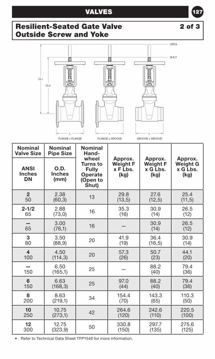
127VALVES
Nominal Valve Size
Nominal Pipe Size
Nominal Hand-wheel
Turns to Fully
Operate (Open to
Shut)
Approx. Weight F x F Lbs.
(kg)
Approx. Weight F x G Lbs.
(kg)
Approx. Weight G x G Lbs.
(kg)ANSI
Inches DN
O.D. Inches (mm)
2 50
2.38 (60,3) 13 29.8
(13,5)27.6
(12,5)25.4 (11,5)
2-1/2 65
2.88 (73,0) 16 35.3
(16)30.9 (14)
26.5 (12)
— 65
3.00 (76,1) 16 — 30.9
(14)26.5 (12)
3 80
3.50 (88,9) 20 41.9
(19)36.4 (16,5)
30.9 (14)
4 100
4.50 (114,3) 20 57.3
(26)50.7 (23)
44.1 (20)
— 150
6.50 (165,1) 25 — 88.2
(40)79.4 (36)
6 150
6.63 (168,3) 25 97.0
(44)88.2 (40)
79.4 (36)
8 200
8.63 (219,1) 34 154.4
(70)143.3 (65)
110.3 (50)
10 250
10.75 (273,1) 42 264.6
(120)242.6 (110)
220.5 (100)
12 300
12.75 (323,9) 50 330.8
(150)297.7 (135)
275.6 (125)
• Refer to Technical Data Sheet TFP1540 for more information.
2 of 3Resilient-Seated Gate Valve Outside Screw and Yoke
FLANGE x FLANGE
L
FLANGE x GROOVE
L
GROOVE x GROOVE
L
CL2
CL1
SHUT
OPEN
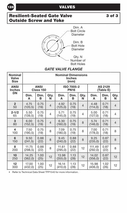
128
Nominal Valve Size
Nominal Dimensions Inches (mm)
ANSI Inches
DN
ANSI Class 150
ISO 7005-2 PN16
AS 2129 (Table E)
Dim. A
Dim. B
Qty. N
Dim. A
Dim. B
Qty. N
Dim. A
Dim. B
Qty. N
2 50
4.75 (120,5)
0.75 (19) 4 4.92
(125,0)0.75 (19) 4 4.48
(114,0)0.71 (18) 4
2-1/2 65
5.50 (139,5)
0.75 (19) 4 5.71
(145,0)0.75 (19) 4 5.00
(127,0)0.71 (18) 4
3 80
6.00 (152,5)
0.75 (19) 4 6.30
(160,0)0.75 (19) 8 5.74
(146,0)0.71 (18) 4
4 100
7.50 (190,5)
0.75 (19) 8 7.09
(180,0)0.75 (19) 8 7.00
(178,0)0.71 (18) 8
6 150
9.50 (241,5)
0.88 (22) 8 9.45
(240,0)0.88 (22) 8 9.25
(235,0)0.87 (22) 8
8 200
11.75 (298,5)
0.88 (22) 8 11.61
(295,0)0.88 (22) 12 111.49
(292,0)0.87 (22) 8
10 250
14.25 (362,0)
1.00 (25) 12 13.98
(355,0)1.13 (28) 12 14.02
(356,0)0.87 (22) 12
12 300
17.00 (432,0)
1.00 (25) 12 16.14
(410,0)1.13 (28) 12 15.98
(406,0)1.02 (26) 12
• Refer to Technical Data Sheet TFP1540 for more information.
GATE VALVE FLANGE
3 of 3Resilient-Seated Gate Valve Outside Screw and Yoke
VALVES
Dim. ABolt CircleDiameter
Dim. BBolt HoleDiameter
Qty. NNumber ofBolt Holes
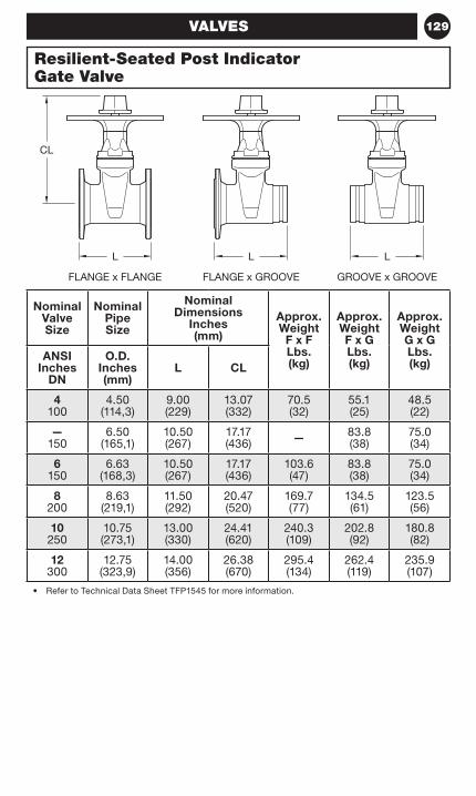
129
Nominal Valve Size
Nominal Pipe Size
Nominal Dimensions
Inches (mm)
Approx. Weight
F x F Lbs. (kg)
Approx. Weight F x G Lbs. (kg)
Approx. Weight G x G Lbs. (kg)
ANSI Inches
DN
O.D. Inches (mm)
L CL
4 100
4.50 (114,3)
9.00 (229)
13.07 (332)
70.5 (32)
55.1 (25)
48.5 (22)
— 150
6.50 (165,1)
10.50 (267)
17.17 (436) — 83.8
(38)75.0 (34)
6 150
6.63 (168,3)
10.50 (267)
17.17 (436)
103.6 (47)
83.8 (38)
75.0 (34)
8 200
8.63 (219,1)
11.50 (292)
20.47 (520)
169.7 (77)
134.5 (61)
123.5 (56)
10 250
10.75 (273,1)
13.00 (330)
24.41 (620)
240.3 (109)
202.8 (92)
180.8 (82)
12 300
12.75 (323,9)
14.00 (356)
26.38 (670)
295.4 (134)
262.4 (119)
235.9 (107)
• Refer to Technical Data Sheet TFP1545 for more information.
Resilient-Seated Post Indicator Gate Valve
VALVES
FLANGE x GROOVE
L
FLANGE x FLANGE
CL
GROOVE x GROOVE
L L
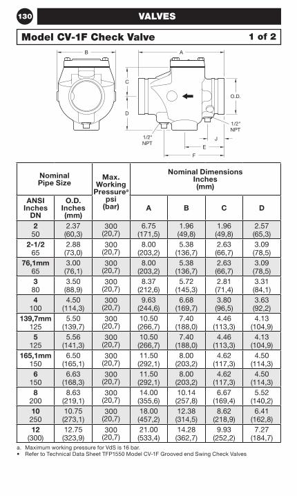
130
Nominal Pipe Size
Max. Working
Pressurea psi
(bar)
Nominal Dimensions Inches (mm)
ANSI Inches
DN
O.D. Inches (mm)
A B C D
2 50
2.37 (60,3)
300 (20,7)
6.75 (171,5)
1.96 (49,8)
1.96 (49,8)
2.57 (65,3)
2-1/2 65
2.88 (73,0)
300 (20,7)
8.00 (203,2)
5.38 (136,7)
2.63 (66,7)
3.09 (78,5)
76,1mm 65
3.00 (76,1)
300 (20,7)
8.00 (203,2)
5.38 (136,7)
2.63 (66,7)
3.09 (78,5)
3 80
3.50 (88,9)
300 (20,7)
8.37 (212,6)
5.72 (145,3)
2.81 (71,4)
3.31 (84,1)
4 100
4.50 (114,3)
300 (20,7)
9.63 (244,6)
6.68 (169,7)
3.80 (96,5)
3.63 (92,2)
139,7mm 125
5.50 (139,7)
300 (20,7)
10.50 (266,7)
7.40 (188,0)
4.46 (113,3)
4.13 (104,9)
5 125
5.56 (141,3)
300 (20,7)
10.50 (266,7)
7.40 (188,0)
4.46 (113,3)
4.13 (104,9)
165,1mm 150
6.50 (165,1)
300 (20,7)
11.50 (292,1)
8.00 (203,2)
4.62 (117,3)
4.50 (114,3)
6 150
6.63 (168,3)
300 (20,7)
11.50 (292,1)
8.00 (203,2)
4.62 (117,3)
4.50 (114,3)
8 200
8.63 (219,1)
300 (20,7)
14.00 (355,6)
10.14 (257,8)
6.67 (169,4)
5.52 (140,2)
10 250
10.75 (273,1)
300 (20,7)
18.00 (457,2)
12.38 (314,5)
8.62 (218,9)
6.41 (162,8)
12 (300)
12.75 (323,9)
300 (20,7)
21.00 (533,4)
14.28 (362,7)
9.93 (252,2)
7.27 (184,7)
a. Maximum working pressure for VdS is 16 bar.• Refer to Technical Data Sheet TFP1550 Model CV-1F Grooved end Swing Check Valves
Model CV-1F Check Valve 1 of 2
VALVES
NPT1/2"
NPT1/2"
B A
C
D
O.D.
J
E
F
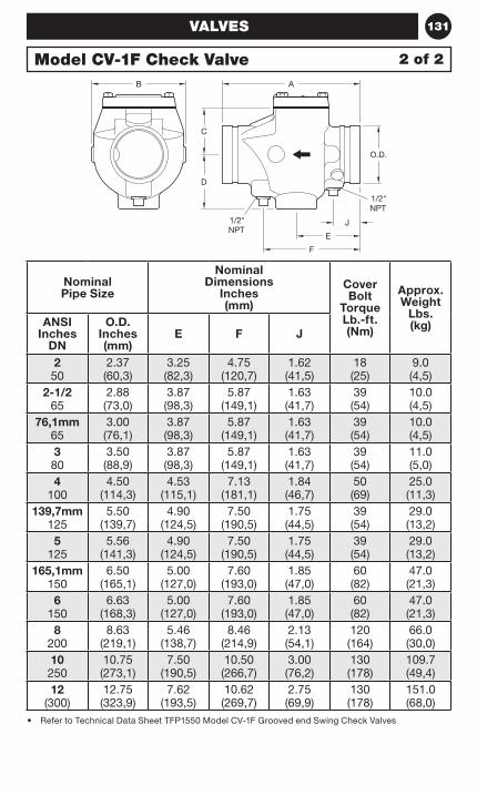
131
Nominal Pipe Size
Nominal Dimensions
Inches (mm)
Cover Bolt
Torque Lb.-ft. (Nm)
Approx. Weight
Lbs. (kg)ANSI
Inches DN
O.D. Inches (mm)
E F J
2 50
2.37 (60,3)
3.25 (82,3)
4.75 (120,7)
1.62 (41,5)
18 (25)
9.0 (4,5)
2-1/2 65
2.88 (73,0)
3.87 (98,3)
5.87 (149,1)
1.63 (41,7)
39 (54)
10.0 (4,5)
76,1mm 65
3.00 (76,1)
3.87 (98,3)
5.87 (149,1)
1.63 (41,7)
39 (54)
10.0 (4,5)
3 80
3.50 (88,9)
3.87 (98,3)
5.87 (149,1)
1.63 (41,7)
39 (54)
11.0 (5,0)
4 100
4.50 (114,3)
4.53 (115,1)
7.13 (181,1)
1.84 (46,7)
50 (69)
25.0 (11,3)
139,7mm 125
5.50 (139,7)
4.90 (124,5)
7.50 (190,5)
1.75 (44,5)
39 (54)
29.0 (13,2)
5 125
5.56 (141,3)
4.90 (124,5)
7.50 (190,5)
1.75 (44,5)
39 (54)
29.0 (13,2)
165,1mm 150
6.50 (165,1)
5.00 (127,0)
7.60 (193,0)
1.85 (47,0)
60 (82)
47.0 (21,3)
6 150
6.63 (168,3)
5.00 (127,0)
7.60 (193,0)
1.85 (47,0)
60 (82)
47.0 (21,3)
8 200
8.63 (219,1)
5.46 (138,7)
8.46 (214,9)
2.13 (54,1)
120 (164)
66.0 (30,0)
10 250
10.75 (273,1)
7.50 (190,5)
10.50 (266,7)
3.00 (76,2)
130 (178)
109.7 (49,4)
12 (300)
12.75 (323,9)
7.62 (193,5)
10.62 (269,7)
2.75 (69,9)
130 (178)
151.0 (68,0)
• Refer to Technical Data Sheet TFP1550 Model CV-1F Grooved end Swing Check Valves
Model CV-1F Check Valve 2 of 2
VALVES
NPT1/2"
NPT1/2"
B A
C
D
O.D.
J
E
F

132 NOTES
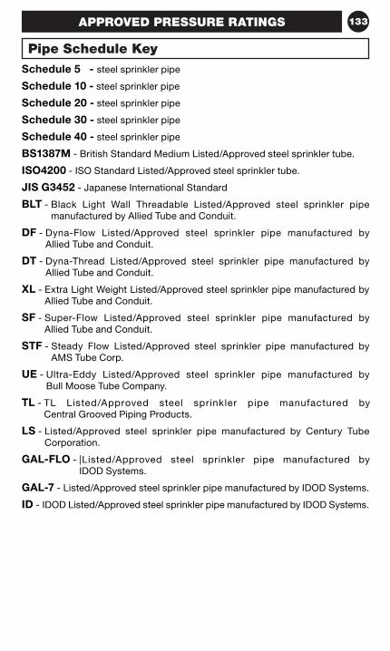
133
Schedule 5 - steel sprinkler pipe
Schedule 10 - steel sprinkler pipe
Schedule 20 - steel sprinkler pipe
Schedule 30 - steel sprinkler pipe
Schedule 40 - steel sprinkler pipe
BS1387M - British Standard Medium Listed/Approved steel sprinkler tube.
ISO4200 - ISO Standard Listed/Approved steel sprinkler tube.
JIS G3452 - Japanese International Standard
BLT - Black Light Wall Threadable Listed/Approved steel sprinkler pipe manufactured by Allied Tube and Conduit.
DF - Dyna-Flow Listed/Approved steel sprinkler pipe manufactured by Allied Tube and Conduit.
DT - Dyna-Thread Listed/Approved steel sprinkler pipe manufactured by Allied Tube and Conduit.
XL - Extra Light Weight Listed/Approved steel sprinkler pipe manufactured by Allied Tube and Conduit.
SF - Super-Flow Listed/Approved steel sprinkler pipe manufactured by Allied Tube and Conduit.
STF - Steady Flow Listed/Approved steel sprinkler pipe manufactured by AMS Tube Corp.
UE - Ultra-Eddy Listed/Approved steel sprinkler pipe manufactured by Bull Moose Tube Company.
TL - TL Listed/Approved steel sprinkler pipe manufactured by Central Grooved Piping Products.
LS - Listed/Approved steel sprinkler pipe manufactured by Century Tube Corporation.
GAL-FLO - |Listed/Approved steel sprinkler pipe manufactured by IDOD Systems.
GAL-7 - Listed/Approved steel sprinkler pipe manufactured by IDOD Systems.
ID - IDOD Listed/Approved steel sprinkler pipe manufactured by IDOD Systems.
Pipe Schedule Key
APPROVED PRESSURE RATINGS
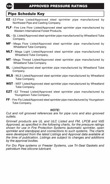
134
EZ - EZ-Flow Listed/Approved steel sprinkler pipe manufactured by Northwest Pipe and Casting Company.
FLF - Fire Line Flow Listed/Approved steel sprinkler pipe manufactured by Western International Forest Products.
GL - GL Listed/Approved steel sprinkler pipe manufactured by Wheatland Tube Company.
MF - Mega Flow Listed/Approved steel sprinkler pipe manufactured by Wheatland Tube Company.
MLT - Mega Light Listed/Approved steel sprinkler pipe manufactured by Wheatland Tube Company.
MT - Mega Thread Listed/Approved steel sprinkler pipe manufactured by Wheatland Tube Company.
SL - Listed/Approved steel sprinkler pipe manufactured by Wheatland Tube Company.
WLS - WLS Listed/Approved steel sprinkler pipe manufactured by Wheatland Tube Company.
WST - WST Listed/Approved steel sprinkler pipe manufactured by Wheatland Tube Company.
EZT - EZ Thread Listed/Approved steel sprinkler pipe manufactured by Youngstown Tube Company.
FF - Fire-Flo Listed/Approved steel sprinkler pipe manufactured by Youngstown Tube Company.
NOTE:Cut and roll grooved references are for pipe runs and also grooved outlets.
Grinnell products are UL and ULC Listed and FM, LPCB and VdS Approved, as specified in the following charts, for the pressure ratings shown for use in Fire Protection Systems (automatic sprinkler, open sprinkler and standpipe) and connections to such systems. The charts were developed from the latest Listings and Approval data available at the time of publication. Listings are subject to changes and additions by the approval bodies.
For Dry Pipe systems or Freezer Systems, use Tri-Seal Gaskets and petroleum free silicone lubricant.
Pipe Schedule Key
APPROVED PRESSURE RATINGS
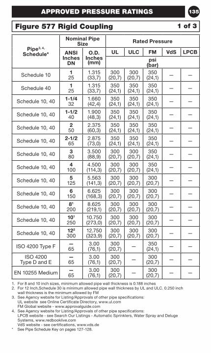
135
1. For 8 and 10 inch sizes, minimum allowed pipe wall thickness is 0.188 inches2. For 12 Inch,Schedule 30 is minimum allowed pipe wall thickness by UL and ULC. 0.250 inch
wall thickness is the minimum allowed by FM3. See Agency website for Listing/Approvals of other pipe specifications:
UL website see Online Certificate Directory, www.ul.com FM Global website - www.approvalguide.com
4. See Agency website for Listing/Approvals of other pipe specifications: LPCB website - see Search Our Listings - Automatic Sprinklers, Water Spray and Deluge Systems, www.redbooklive.com VdS website - see certifications, www.vds.de
* See Pipe Schedule Key on pages 127-128.
Pipe3, 4, Schedule*
Nominal Pipe Size Rated Pressure
ANSI Inches
DN
O.D. Inches (mm)
UL ULC FM VdS LPCBpsi
(bar)
Schedule 10 1 25
1.315 (33,7)
300 (20,7)
300 (20,7)
350 (24,1) — —
Schedule 40 1 25
1.315 (33,7)
350 (24,1)
350 (24,1)
350 (24,1) — —
Schedule 10, 40 1-1/4 32
1.660 (42,4)
350 (24,1)
350 (24,1)
350 (24,1) — —
Schedule 10, 40 1-1/2 40
1.900 (48,3)
350 (24,1)
350 (24,1)
350 (24,1) — —
Schedule 10, 40 2 50
2.375 (60,3)
350 (24,1)
350 (24,1)
350 (24,1) — —
Schedule 10, 40 2-1/2 65
2.875 (73,0)
350 (24,1)
350 (24,1)
350 (24,1) — —
Schedule 10, 40 3 80
3.500 (88,9)
300 (20,7)
300 (20,7)
350 (24,1) — —
Schedule 10, 40 4 100
4.500 (114,3)
300 (20,7)
300 (20,7)
350 (24,1) — —
Schedule 10, 40 5 125
5.563 (141,3)
300 (20,7)
300 (20,7)
300 (20,7) — —
Schedule 10, 40 6 150
6.625 (168,3)
300 (20,7)
300 (20,7)
300 (20,7) — —
Schedule 10, 40 81 200
8.625 (219,1)
300 (20,7)
300 (20,7)
300 (20,7) — —
Schedule 10, 40 101 250
10.750 (273,0)
300 (20,7)
300 (20,7)
300 (20,7) — —
Schedule 10, 40 122 300
12.750 (323,9)
300 (20,7)
300 (20,7)
300 (20,7) — —
ISO 4200 Type F — 65
3.00 (76,1)
300 (20,7) — 350
(24,1) — —
ISO 4200 Type D and E
— 65
3.00 (76,1)
300 (20,7) — 300
(20,7) — —
EN 10255 Medium — 65
3.00 (76,1)
300 (20,7) — 300
(20,7) — —
APPROVED PRESSURE RATINGS
Figure 577 Rigid Coupling 1 of 3
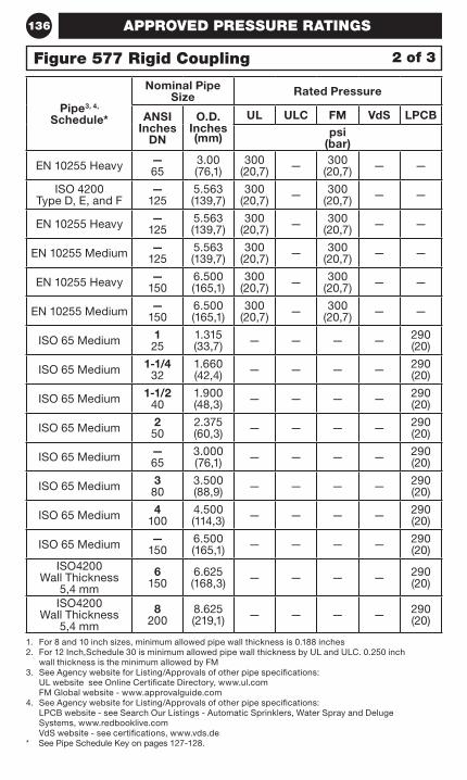
136
1. For 8 and 10 inch sizes, minimum allowed pipe wall thickness is 0.188 inches2. For 12 Inch,Schedule 30 is minimum allowed pipe wall thickness by UL and ULC. 0.250 inch
wall thickness is the minimum allowed by FM3. See Agency website for Listing/Approvals of other pipe specifications:
UL website see Online Certificate Directory, www.ul.com FM Global website - www.approvalguide.com
4. See Agency website for Listing/Approvals of other pipe specifications: LPCB website - see Search Our Listings - Automatic Sprinklers, Water Spray and Deluge Systems, www.redbooklive.com VdS website - see certifications, www.vds.de
* See Pipe Schedule Key on pages 127-128.
Pipe3, 4, Schedule*
Nominal Pipe Size Rated Pressure
ANSI Inches
DN
O.D. Inches (mm)
UL ULC FM VdS LPCBpsi
(bar)
EN 10255 Heavy — 65
3.00 (76,1)
300 (20,7) — 300
(20,7) — —
ISO 4200 Type D, E, and F
— 125
5.563 (139,7)
300 (20,7) — 300
(20,7) — —
EN 10255 Heavy — 125
5.563 (139,7)
300 (20,7) — 300
(20,7) — —
EN 10255 Medium — 125
5.563 (139,7)
300 (20,7) — 300
(20,7) — —
EN 10255 Heavy — 150
6.500 (165,1)
300 (20,7) — 300
(20,7) — —
EN 10255 Medium — 150
6.500 (165,1)
300 (20,7) — 300
(20,7) — —
ISO 65 Medium 1 25
1.315 (33,7) — — — — 290
(20)
ISO 65 Medium 1-1/4 32
1.660 (42,4) — — — — 290
(20)
ISO 65 Medium 1-1/2 40
1.900 (48,3) — — — — 290
(20)
ISO 65 Medium 2 50
2.375 (60,3) — — — — 290
(20)
ISO 65 Medium — 65
3.000 (76,1) — — — — 290
(20)
ISO 65 Medium 3 80
3.500 (88,9) — — — — 290
(20)
ISO 65 Medium 4 100
4.500 (114,3) — — — — 290
(20)
ISO 65 Medium — 150
6.500 (165,1) — — — — 290
(20)ISO4200
Wall Thickness 5,4 mm
6 150
6.625 (168,3) — — — — 290
(20)
ISO4200 Wall Thickness
5,4 mm
8200
8.625 (219,1) — — — — 290
(20)
APPROVED PRESSURE RATINGS
Figure 577 Rigid Coupling 2 of 3
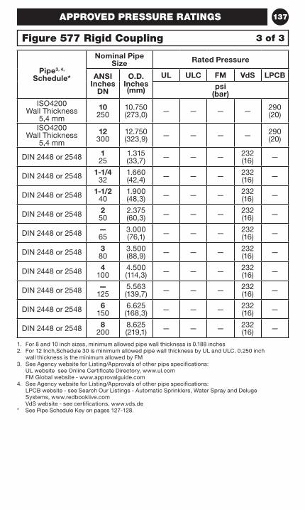
137
1. For 8 and 10 inch sizes, minimum allowed pipe wall thickness is 0.188 inches2. For 12 Inch,Schedule 30 is minimum allowed pipe wall thickness by UL and ULC. 0.250 inch
wall thickness is the minimum allowed by FM3. See Agency website for Listing/Approvals of other pipe specifications:
UL website see Online Certificate Directory, www.ul.com FM Global website - www.approvalguide.com
4. See Agency website for Listing/Approvals of other pipe specifications: LPCB website - see Search Our Listings - Automatic Sprinklers, Water Spray and Deluge Systems, www.redbooklive.com VdS website - see certifications, www.vds.de
* See Pipe Schedule Key on pages 127-128.
Pipe3, 4, Schedule*
Nominal Pipe Size Rated Pressure
ANSI Inches
DN
O.D. Inches (mm)
UL ULC FM VdS LPCBpsi
(bar)ISO4200
Wall Thickness 5,4 mm
10 250
10.750 (273,0) — — — — 290
(20)
ISO4200 Wall Thickness
5,4 mm
12 300
12.750 (323,9) — — — — 290
(20)
DIN 2448 or 2548 1 25
1.315 (33,7) — — — 232
(16) —
DIN 2448 or 2548 1-1/4 32
1.660 (42,4) — — — 232
(16) —
DIN 2448 or 2548 1-1/2 40
1.900 (48,3) — — — 232
(16) —
DIN 2448 or 2548 2 50
2.375 (60,3) — — — 232
(16) —
DIN 2448 or 2548 — 65
3.000 (76,1) — — — 232
(16) —
DIN 2448 or 2548 3 80
3.500 (88,9) — — — 232
(16) —
DIN 2448 or 2548 4 100
4.500 (114,3) — — — 232
(16) —
DIN 2448 or 2548 — 125
5.563 (139,7) — — — 232
(16) —
DIN 2448 or 2548 6 150
6.625 (168,3) — — — 232
(16) —
DIN 2448 or 2548 8 200
8.625 (219,1) — — — 232
(16) —
APPROVED PRESSURE RATINGS
Figure 577 Rigid Coupling 3 of 3
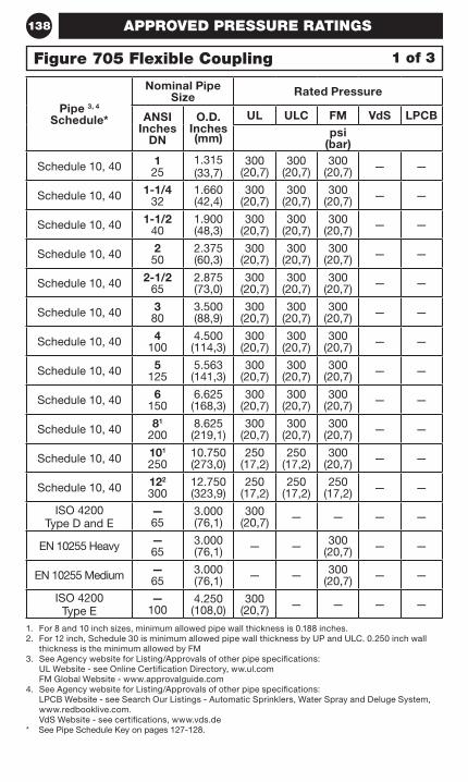
138
1. For 8 and 10 inch sizes, minimum allowed pipe wall thickness is 0.188 inches.2. For 12 inch, Schedule 30 is minimum allowed pipe wall thickness by UP and ULC. 0.250 inch wall
thickness is the minimum allowed by FM3. See Agency website for Listing/Approvals of other pipe specifications:
UL Website - see Online Certification Directory, ww.ul.com FM Global Website - www.approvalguide.com
4. See Agency website for Listing/Approvals of other pipe specifications: LPCB Website - see Search Our Listings - Automatic Sprinklers, Water Spray and Deluge System, www.redbooklive.com. VdS Website - see certifications, www.vds.de
* See Pipe Schedule Key on pages 127-128.
Pipe 3, 4 Schedule*
Nominal Pipe Size Rated Pressure
ANSI Inches
DN
O.D. Inches (mm)
UL ULC FM VdS LPCBpsi
(bar)
Schedule 10, 40 1 25
1.315 (33,7)
300 (20,7)
300 (20,7)
300 (20,7) — —
Schedule 10, 40 1-1/4 32
1.660 (42,4)
300 (20,7)
300 (20,7)
300 (20,7) — —
Schedule 10, 40 1-1/2 40
1.900 (48,3)
300 (20,7)
300 (20,7)
300 (20,7) — —
Schedule 10, 40 2 50
2.375 (60,3)
300 (20,7)
300 (20,7)
300 (20,7) — —
Schedule 10, 40 2-1/2 65
2.875 (73,0)
300 (20,7)
300 (20,7)
300 (20,7) — —
Schedule 10, 40 3 80
3.500 (88,9)
300 (20,7)
300 (20,7)
300 (20,7) — —
Schedule 10, 40 4 100
4.500 (114,3)
300 (20,7)
300 (20,7)
300 (20,7) — —
Schedule 10, 40 5 125
5.563 (141,3)
300 (20,7)
300 (20,7)
300 (20,7) — —
Schedule 10, 40 6 150
6.625 (168,3)
300 (20,7)
300 (20,7)
300 (20,7) — —
Schedule 10, 40 81 200
8.625 (219,1)
300 (20,7)
300 (20,7)
300 (20,7) — —
Schedule 10, 40 101 250
10.750 (273,0)
250 (17,2)
250 (17,2)
300 (20,7) — —
Schedule 10, 40 122 300
12.750 (323,9)
250 (17,2)
250 (17,2)
250 (17,2) — —
ISO 4200 Type D and E
— 65
3.000 (76,1)
300 (20,7) — — — —
EN 10255 Heavy — 65
3.000 (76,1) — — 300
(20,7) — —
EN 10255 Medium — 65
3.000 (76,1) — — 300
(20,7) — —
ISO 4200 Type E
— 100
4.250 (108,0)
300 (20,7) — — — —
APPROVED PRESSURE RATINGS
Figure 705 Flexible Coupling 1 of 3
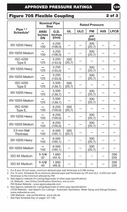
139
1. For 8 and 10 inch sizes, minimum allowed pipe wall thickness is 0.188 inches.2. For 12 inch, Schedule 30 is minimum allowed pipe wall thickness by UP and ULC. 0.250 inch wall
thickness is the minimum allowed by FM3. See Agency website for Listing/Approvals of other pipe specifications:
UL Website - see Online Certification Directory, ww.ul.com FM Global Website - www.approvalguide.com
4. See Agency website for Listing/Approvals of other pipe specifications: LPCB Website - see Search Our Listings - Automatic Sprinklers, Water Spray and Deluge System, www.redbooklive.com. VdS Website - see certifications, www.vds.de
* See Pipe Schedule Key on pages 127-128.
Pipe 3, 4 Schedule*
Nominal Pipe Size Rated Pressure
ANSI Inches
DN
O.D. Inches (mm)
UL ULC FM VdS LPCBpsi
(bar)
EN 10255 Heavy — 100
4.250 (108,0) — — 300
(20,7) — —
EN 10255 Medium — 100
4.250 (108,0) — — 300
(20,7) — —
ISO 4200Type E
— 125
5.250 (133,0)
300 (20,7) — — — —
EN 10255 Heavy — 125
5.250 (133,0) — — 300
(20,7) — —
EN 10255 Medium — 125
5.250 (133,0) — — 300
(20,7) — —
ISO 4200Type E
— 125
5.500 (139,7)
300 (20,7) — — — —
EN 10255 Heavy — 125
5.500 (139,7) — — 300
(20,7) — —
EN 10255 Medium — 125
5.500 (139,7) — — 300
(20,7) — —
ISO 4200Type E,
— 150
6.250 (159,0)
300 (20,7) — — — —
EN 10255 Heavy — 150
6.250 (159,0) — — 300
(20,7) — —
EN 10255 Medium — 150
6.250 (159,0) — — 300
(20,7) — —
2.5 mm Wall Thickness
— 150
6.500 (165,1)
300 (20,7) — — — —
EN 10255 Heavy — 150
6.500 (165,1) — — 300
(20,7) — —
EN 10255 Medium — 150
6.500 (165,1) — — 300
(20,7) — —
ISO 65 Medium 1-1/4 32
1.660 (42,4) — — — — 290
(20)
ISO 65 Medium 1-1/2 40
1.900 (48,3) — — — — 290
(20)
2 of 3Figure 705 Flexible Coupling
APPROVED PRESSURE RATINGS
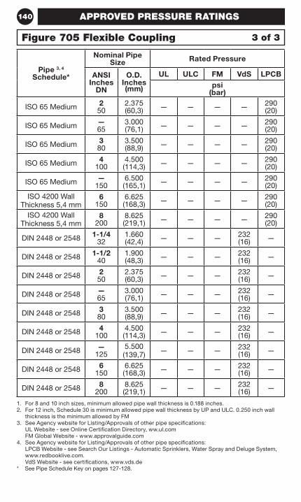
140
1. For 8 and 10 inch sizes, minimum allowed pipe wall thickness is 0.188 inches.2. For 12 inch, Schedule 30 is minimum allowed pipe wall thickness by UP and ULC. 0.250 inch wall
thickness is the minimum allowed by FM3. See Agency website for Listing/Approvals of other pipe specifications:
UL Website - see Online Certification Directory, ww.ul.com FM Global Website - www.approvalguide.com
4. See Agency website for Listing/Approvals of other pipe specifications: LPCB Website - see Search Our Listings - Automatic Sprinklers, Water Spray and Deluge System, www.redbooklive.com. VdS Website - see certifications, www.vds.de
* See Pipe Schedule Key on pages 127-128.
Pipe 3, 4 Schedule*
Nominal Pipe Size Rated Pressure
ANSI Inches
DN
O.D. Inches (mm)
UL ULC FM VdS LPCBpsi
(bar)
ISO 65 Medium 2 50
2.375 (60,3) — — — — 290
(20)
ISO 65 Medium — 65
3.000 (76,1) — — — — 290
(20)
ISO 65 Medium 3 80
3.500 (88,9) — — — — 290
(20)
ISO 65 Medium 4 100
4.500 (114,3) — — — — 290
(20)
ISO 65 Medium — 150
6.500 (165,1) — — — — 290
(20)ISO 4200 Wall
Thickness 5,4 mm6
1506.625 (168,3) — — — — 290
(20)ISO 4200 Wall
Thickness 5,4 mm8
2008.625 (219,1) — — — — 290
(20)
DIN 2448 or 2548 1-1/4 32
1.660 (42,4) — — — 232
(16) —
DIN 2448 or 2548 1-1/2 40
1.900 (48,3) — — — 232
(16) —
DIN 2448 or 2548 2 50
2.375 (60,3) — — — 232
(16) —
DIN 2448 or 2548 — 65
3.000 (76,1) — — — 232
(16) —
DIN 2448 or 2548 3 80
3.500 (88,9) — — — 232
(16) —
DIN 2448 or 2548 4 100
4.500 (114,3) — — — 232
(16) —
DIN 2448 or 2548 — 125
5.500 (139,7) — — — 232
(16) —
DIN 2448 or 2548 6 150
6.625 (168,3) — — — 232
(16) —
DIN 2448 or 2548 8 200
8.625 (219,1) — — — 232
(16) —
3 of 3Figure 705 Flexible Coupling
APPROVED PRESSURE RATINGS
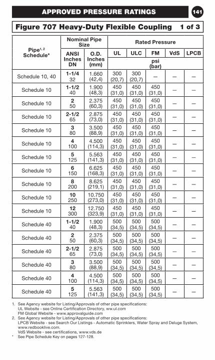
141
1. See Agency website for Listing/Approvals of other pipe specifications: UL Website - see Online Certification Directory, ww.ul.com FM Global Website - www.approvalguide.com
2. See Agency website for Listing/Approvals of other pipe specifications: LPCB Website - see Search Our Listings - Automatic Sprinklers, Water Spray and Deluge System, www.redbooklive.com. VdS Website - see certifications, www.vds.de
* See Pipe Schedule Key on pages 127-128.
Pipe1, 2 Schedule*
Nominal Pipe Size Rated Pressure
ANSI Inches
DN
O.D. Inches (mm)
UL ULC FM VdS LPCBpsi
(bar)
Schedule 10, 40 1-1/4 32
1.660 (42,4)
300 (20,7)
300 (20,7) — — —
Schedule 10 1-1/2 40
1.900 (48,3)
450 (31,0)
450 (31,0)
450 (31,0) — —
Schedule 10 2 50
2.375 (60,3)
450 (31,0)
450 (31,0)
450 (31,0) — —
Schedule 10 2-1/2 65
2.875 (73,0)
450 (31,0)
450 (31,0)
450 (31,0) — —
Schedule 10 3 80
3.500 (88,9)
450 (31,0)
450 (31,0)
450 (31,0) — —
Schedule 10 4 100
4.500 (114,3)
450 (31,0)
450 (31,0)
450 (31,0) — —
Schedule 10 5 125
5.563 (141,3)
450 (31,0)
450 (31,0)
450 (31,0) — —
Schedule 10 6 150
6.625 (168,3)
450 (31,0)
450 (31,0)
450 (31,0) — —
Schedule 10 8 200
8.625 (219,1)
450 (31,0)
450 (31,0)
450 (31,0) — —
Schedule 10 10 250
10.750 (273,0)
450 (31,0)
450 (31,0)
450 (31,0) — —
Schedule 10 12 300
12.750 (323,9)
450 (31,0)
450 (31,0)
450 (31,0) — —
Schedule 40 1-1/2 40
1.900 (48,3)
500 (34,5)
500 (34,5)
500 (34,5) — —
Schedule 40 2 50
2.375 (60,3)
500 (34,5)
500 (34,5)
500 (34,5) — —
Schedule 40 2-1/2 65
2.875 (73,0)
500 (34,5)
500 (34,5)
500 (34,5) — —
Schedule 40 3 80
3.500 (88,9)
500 (34,5)
500 (34,5)
500 (34,5) — —
Schedule 40 4 100
4.500 (114,3)
500 (34,5)
500 (34,5)
500 (34,5) — —
Schedule 40 5 125
5.563 (141,3)
500 (34,5)
500 (34,5)
500 (34,5) — —
1 of 3Figure 707 Heavy-Duty Flexible Coupling
APPROVED PRESSURE RATINGS
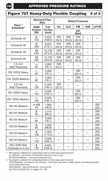
142
1. See Agency website for Listing/Approvals of other pipe specifications: UL Website - see Online Certification Directory, ww.ul.com FM Global Website - www.approvalguide.com
2. See Agency website for Listing/Approvals of other pipe specifications: LPCB Website - see Search Our Listings - Automatic Sprinklers, Water Spray and Deluge System, www.redbooklive.com. VdS Website - see certifications, www.vds.de
* See Pipe Schedule Key on pages 127-128.
Pipe1, 2 Schedule*
Nominal Pipe Size Rated Pressure
ANSI Inches
DN
O.D. Inches (mm)
UL ULC FM VdS LPCBpsi
(bar)
Schedule 40 6 150
6.625 (168,3)
500 (34,5)
500 (34,5)
500 (34,5) — —
Schedule 40 8 200
8.625 (219,1)
500 (34,5)
500 (34,5)
500 (34,5) — —
Schedule 40 10 250
10.750 (273,0)
500 (34,5)
500 (34,5)
500 (34,5) — —
Schedule 40 12 300
12.750(323,9)
500 (34,5)
500 (34,5)
500 (34,5) — —
2.5 mm Wall Thickness
— 65
3.000 (76,1)
300 (20,7) — — — —
EN 10255 Heavy — 65
3.000 (76,1) — — 300
(20,7) — —
EN 10255 Medium — 65
3.000 (76,1) — — 300
(20,7) — —
5.0 mm Wall Thickness
— 150
6.500 (165,1)
300 (20,7) — — — —
EN 10255 Heavy — 150
6.500 (165,1) — — 300
(20,7) — —
EN 10255 Medium — 150
6.500 (165,1) — — 300
(20,7) — —
ISO 65 Medium 1-1/2 40
1.900 (48,3) — — — — 290
(20)
ISO 65 Medium 2 50
2.375 (60,3) — — — — 290
(20)
ISO 65 Medium — 65
3.000 (76,1) — — — — 290
(20)
ISO 65 Medium 3 80
3.500 (88,9) — — — — 290
(20)
ISO 65 Medium 4 100
4.500 (114,3) — — — — 290
(20)
ISO 65 Medium — 150
6.500 (165,1) — — — — 290
(20)ISO 4200 Wall
Thickness 5,4 mm6
1506.625 (168,3) — — — — 290
(20)
2 of 3Figure 707 Heavy-Duty Flexible Coupling
APPROVED PRESSURE RATINGS
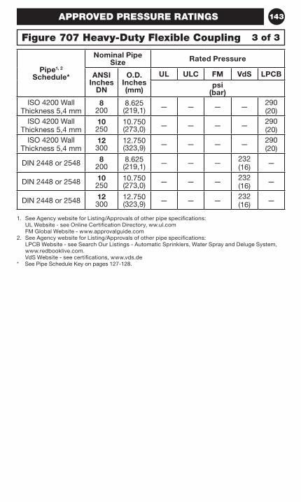
143
1. See Agency website for Listing/Approvals of other pipe specifications: UL Website - see Online Certification Directory, ww.ul.com FM Global Website - www.approvalguide.com
2. See Agency website for Listing/Approvals of other pipe specifications: LPCB Website - see Search Our Listings - Automatic Sprinklers, Water Spray and Deluge System, www.redbooklive.com. VdS Website - see certifications, www.vds.de
* See Pipe Schedule Key on pages 127-128.
Pipe1, 2 Schedule*
Nominal Pipe Size Rated Pressure
ANSI Inches
DN
O.D. Inches (mm)
UL ULC FM VdS LPCBpsi
(bar)ISO 4200 Wall
Thickness 5,4 mm8
2008.625 (219,1) — — — — 290
(20)ISO 4200 Wall
Thickness 5,4 mm10 250
10.750 (273,0) — — — — 290
(20)ISO 4200 Wall
Thickness 5,4 mm12 300
12.750 (323,9) — — — — 290
(20)
DIN 2448 or 2548 8 200
8.625 (219,1) — — — 232
(16) —
DIN 2448 or 2548 10 250
10.750 (273,0) — — — 232
(16) —
DIN 2448 or 2548 12 300
12.750 (323,9) — — — 232
(16) —
3 of 3Figure 707 Heavy-Duty Flexible Coupling
APPROVED PRESSURE RATINGS
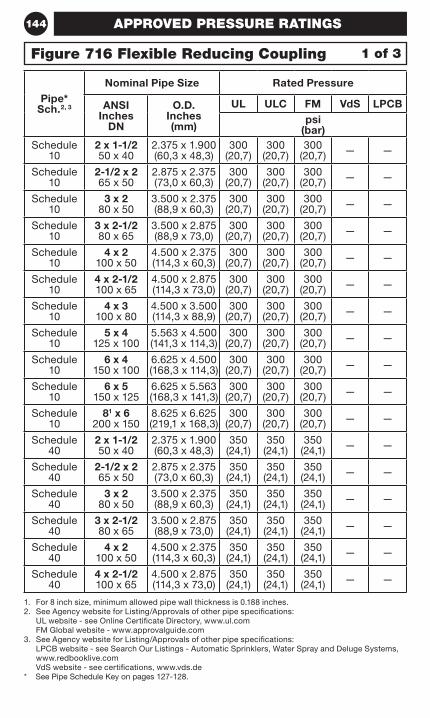
144
1. For 8 inch size, minimum allowed pipe wall thickness is 0.188 inches.2. See Agency website for Listing/Approvals of other pipe specifications:
UL website - see Online Certificate Directory, www.ul.com FM Global website - www.approvalguide.com
3. See Agency website for Listing/Approvals of other pipe specifications: LPCB website - see Search Our Listings - Automatic Sprinklers, Water Spray and Deluge Systems, www.redbooklive.com VdS website - see certifications, www.vds.de
* See Pipe Schedule Key on pages 127-128.
Pipe* Sch.2, 3
Nominal Pipe Size Rated Pressure
ANSI Inches
DN
O.D. Inches (mm)
UL ULC FM VdS LPCBpsi
(bar)Schedule
102 x 1-1/2 50 x 40
2.375 x 1.900 (60,3 x 48,3)
300 (20,7)
300 (20,7)
300 (20,7) — —
Schedule 10
2-1/2 x 2 65 x 50
2.875 x 2.375 (73,0 x 60,3)
300 (20,7)
300 (20,7)
300 (20,7) — —
Schedule 10
3 x 2 80 x 50
3.500 x 2.375 (88,9 x 60,3)
300 (20,7)
300 (20,7)
300 (20,7) — —
Schedule 10
3 x 2-1/2 80 x 65
3.500 x 2.875 (88,9 x 73,0)
300 (20,7)
300 (20,7)
300 (20,7) — —
Schedule 10
4 x 2 100 x 50
4.500 x 2.375 (114,3 x 60,3)
300 (20,7)
300 (20,7)
300 (20,7) — —
Schedule 10
4 x 2-1/2 100 x 65
4.500 x 2.875 (114,3 x 73,0)
300 (20,7)
300 (20,7)
300 (20,7) — —
Schedule 10
4 x 3 100 x 80
4.500 x 3.500 (114,3 x 88,9)
300 (20,7)
300 (20,7)
300 (20,7) — —
Schedule 10
5 x 4 125 x 100
5.563 x 4.500 (141,3 x 114,3)
300 (20,7)
300 (20,7)
300 (20,7) — —
Schedule 10
6 x 4 150 x 100
6.625 x 4.500 (168,3 x 114,3)
300 (20,7)
300 (20,7)
300 (20,7) — —
Schedule 10
6 x 5 150 x 125
6.625 x 5.563 (168,3 x 141,3)
300 (20,7)
300 (20,7)
300 (20,7) — —
Schedule 10
81 x 6 200 x 150
8.625 x 6.625 (219,1 x 168,3)
300 (20,7)
300 (20,7)
300 (20,7) — —
Schedule 40
2 x 1-1/2 50 x 40
2.375 x 1.900 (60,3 x 48,3)
350 (24,1)
350 (24,1)
350 (24,1) — —
Schedule 40
2-1/2 x 2 65 x 50
2.875 x 2.375 (73,0 x 60,3)
350 (24,1)
350 (24,1)
350 (24,1) — —
Schedule 40
3 x 2 80 x 50
3.500 x 2.375 (88,9 x 60,3)
350 (24,1)
350 (24,1)
350 (24,1) — —
Schedule 40
3 x 2-1/2 80 x 65
3.500 x 2.875 (88,9 x 73,0)
350 (24,1)
350 (24,1)
350 (24,1) — —
Schedule 40
4 x 2 100 x 50
4.500 x 2.375 (114,3 x 60,3)
350 (24,1)
350 (24,1)
350 (24,1) — —
Schedule 40
4 x 2-1/2 100 x 65
4.500 x 2.875 (114,3 x 73,0)
350 (24,1)
350 (24,1)
350 (24,1) — —
1 of 3Figure 716 Flexible Reducing Coupling
APPROVED PRESSURE RATINGS
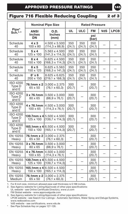
145
1. For 8 inch size, minimum allowed pipe wall thickness is 0.188 inches.2. See Agency website for Listing/Approvals of other pipe specifications:
UL website - see Online Certificate Directory, www.ul.com FM Global website - www.approvalguide.com
3. See Agency website for Listing/Approvals of other pipe specifications: LPCB website - see Search Our Listings - Automatic Sprinklers, Water Spray and Deluge Systems, www.redbooklive.com VdS website - see certifications, www.vds.de
* See Pipe Schedule Key on pages 127-128.
Pipe* Sch.2, 3
Nominal Pipe Size Rated Pressure
ANSI Inches
DN
O.D. Inches (mm)
UL ULC FM VdS LPCBpsi
(bar)Schedule
404 x 3
100 x 804.500 x 3.500 (114,3 x 88,9)
350 (24,1)
350 (24,1)
350 (24,1) — —
Schedule 40
5 x 4 125 x 100
5.563 x 4.500 (141,3 x 114,3)
350 (24,1)
350 (24,1)
350 (24,1) — —
Schedule 40
6 x 4 150 x 100
6.625 x 4.500 (168,3 x 114,3)
350 (24,1)
350 (24,1)
350 (24,1) — —
Schedule 40
6 x 5 150 x 125
6.625 x 5.563 (168,3 x 141,3)
350 (24,1)
350 (24,1)
350 (24,1) — —
Schedule 40
81 x 6 200 x 150
8.625 x 6.625 (219,1 x 168,3)
350 (24,1)
350 (24,1)
350 (24,1) — —
ISO 4200 Type D and E
76.1mm x 2 65 x 50
3.000 x 2.375 (76,1 x 60,3)
300 (20,7) — 300
(20,7) — —
ISO 4200 Type D and E
3 x 76.1mm 80 x 65
3.500 x 3.000 (88,9 x 76,1)
300 (20,7) — 300
(20,7) — —
ISO 4200 Type D and E
4 x 76.1mm 100 x 65
4.500 x 3.000 (114,3 x 76,1)
300 (20,7) — 300
(20,7) — —
ISO 4200 Type D and E
139.7mm x 4 125 x 100
5.500 x 4.500 (139,7 x 114,3)
300 (20,7) — 300
(20,7) — —
ISO 4200 Type D and E
165.1mm x 4 150 x 100
6.500 x 4.500 (165,1 x 114,3)
300 (20,7) — 300
(20,7) — —
EN 10255 Heavy
76.1mm x 2 65 x 50
3.000 x 2.375 (76,1 x 60,3) — — 300
(20,7) — —
EN 10255 Heavy
3 x 76.1mm 80 x 65
3.500 x 3.000 (88,9 x 76,1) — — 300
(20,7) — —
EN 10255 Heavy
4 x 76.1mm 100 x 65
4.500 x 3.000 (114,3 x 76,1) — — 300
(20,7) — —
EN 10255 Heavy
139.7mm x 4 125 x 100
5.500 x 4.500 (139,7 x 114,3) — — 300
(20,7) — —
EN 10255 Heavy
165.1mm x 4 150 x 100
6.500 x 4.500 (165,1 x 114,3) — — 300
(20,7) — —
EN 10255 Medium
76.1mm x 2 65 x 50
3.000 x 2.375 (76,1 x 60,3) — — 300
(20,7) — —
2 of 3Figure 716 Flexible Reducing Coupling
APPROVED PRESSURE RATINGS
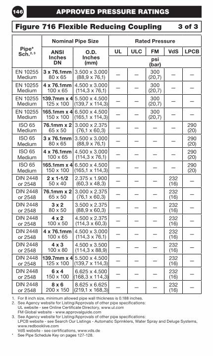
146
1. For 8 inch size, minimum allowed pipe wall thickness is 0.188 inches.2. See Agency website for Listing/Approvals of other pipe specifications:
UL website - see Online Certificate Directory, www.ul.com FM Global website - www.approvalguide.com
3. See Agency website for Listing/Approvals of other pipe specifications: LPCB website - see Search Our Listings - Automatic Sprinklers, Water Spray and Deluge Systems, www.redbooklive.com VdS website - see certifications, www.vds.de
* See Pipe Schedule Key on pages 127-128.
Pipe* Sch.2, 3
Nominal Pipe Size Rated Pressure
ANSI Inches
DN
O.D. Inches (mm)
UL ULC FM VdS LPCBpsi
(bar)EN 10255 Medium
3 x 76.1mm 80 x 65
3.500 x 3.000 (88,9 x 76,1) — — 300
(20,7) — —
EN 10255 Medium
4 x 76.1mm 100 x 65
4.500 x 3.000 (114,3 x 76,1) — — 300
(20,7) — —
EN 10255 Medium
139.7mm x 4 125 x 100
5.500 x 4.500 (139,7 x 114,3) — — 300
(20,7) — —
EN 10255 Medium
165.1mm x 4 150 x 100
6.500 x 4.500 (165,1 x 114,3) — — 300
(20,7) — —
ISO 65 Medium
76.1mm x 2 65 x 50
3.000 x 2.375 (76,1 x 60,3) — — — — 290
(20)
ISO 65 Medium
3 x 76.1mm 80 x 65
3.500 x 3.000 (88,9 x 76,1) — — — — 290
(20)ISO 65
Medium4 x 76.1mm
100 x 654.500 x 3.000 (114,3 x 76,1) — — — — 290
(20)ISO 65
Medium165.1mm x 4
150 x 1006.500 x 4.500 (165,1 x 114,3) — — — — 290
(20)DIN 2448 or 2548
2 x 1-1/2 50 x 40
2.375 x 1.900 (60,3 x 48,3) — — — 232
(16) —
DIN 2448 or 2548
76.1mm x 2 65 x 50
3.000 x 2.375 (76,1 x 60,3) — — — 232
(16) —
DIN 2448 or 2548
3 x 2 80 x 50
3.500 x 2.375 (88,9 x 60,3) — — — 232
(16) —
DIN 2448 or 2548
4 x 2 100 x 50
4.500 x 2.375 (114,3 x 60,3) — — — 232
(16) —
DIN 2448 or 2548
4 x 76.1mm 100 x 65
4.500 x 3.000 (114,3 x 76,1) — — — 232
(16) —
DIN 2448 or 2548
4 x 3 100 x 80
4.500 x 3.500 (114,3 x 88,9) — — — 232
(16) —
DIN 2448 or 2548
139.7mm x 4 125 x 100
5.500 x 4.500 (139,7 x 114,3) — — — 232
(16) —
DIN 2448 or 2548
6 x 4 150 x 100
6.625 x 4.500 (168,3 x 114,3) — — — 232
(16) —
DIN 2448 or 2548
8 x 6 200 x 150
8.625 x 6.625 (219,1 x 168,3) — — — 232
(16) —
3 of 3Figure 716 Flexible Reducing Coupling
APPROVED PRESSURE RATINGS
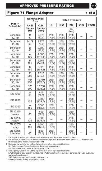
147
1. For 8 and 10 inch sizes, minimum allowed pipe wall thickness is 0.188 inches2. For 12 inch, Schedule 30 in minimum allowed pipe wall thickness by UL and ULC. 0.250 inch wall
thickness is the minimum allowed by FM3. See Agency website for Listing/Approvals of other pipe specifications:
UL Website - see Online Certificate Directory, www.ul.com FM Global Website - www.approvalguide.com
4. See Agency website for Listing/Approvals of other pipe specifications: LPCB Website see Search Our Listings - Automatic Sprinklers, water Spray and Deluge Systems, www.redbooklive.com VdS Website - see certifications, www.vds.de
* See Pipe Schedule Key on pages 127-128.
Pipe3, 4 Schedule*
Nominal Pipe Size Rated Pressure
ANSI Inches
DN
O.D. Inches (mm)
UL ULC FM VdS LPCBpsi
(bar)Schedule
10, 402
502.375(60,3)
250 (17,24)
250 (17,24)
250 (17,24) — —
Schedule 10, 40
2-1/2 65
2.875(73,0)
250 (17,24)
250 (17,24)
250 (17,24) — —
Schedule 10, 40
3 80
3.500(88,9)
250 (17,24)
250 (17,24)
250 (17,24) — —
Schedule 10, 40
4 100
4.500(114,3)
250 (17,24)
250 (17,24)
250 (17,24) — —
Schedule 10, 40
5 125
5.563 (141,3)
250 (17,24)
250 (17,24)
250 (17,24) — —
Schedule 10, 40
6 150
6.625 (168,3)
250 (17,24)
250 (17,24)
250 (17,24) — —
Schedule 10, 40
81 200
8.625 (219,1)
250 (17,24)
250 (17,24)
250 (17,24) — —
Schedule 10, 40
101 250
10.750(273,0)
250 (17,24)
250 (17,24)
250 (17,24) — —
Schedule 10, 40
122 300
12.750(323,9)
250 (17,24)
250 (17,24)
250 (17,24) — —
ISO 4200 — 65
3.00(76,1)
250 (17,24) — 250
(17,24) — —
ISO 4200 — 125
5.500(139,7)
250 (17,24) — 250
(17,24) — —
ISO 4200 — 150
6.500 (165,1)
250 (17,24) — 250
(17,24) — —
EN 10255 Heavy
— 65
3.00(76,1)
250 (17,24) — 250
(17,24) — —
EN 10255 Heavy
— 125
5.500(139,7) — — 250
(17,24) — —
EN 10255 Heavy
— 150
6.500 (165,1)
250 (17,24) — 250
(17,24) — —
EN 10255 Medium
— 65
3.00(76,1)
250 (17,24) — 250
(17,24) — —
1 of 2Figure 71 Flange Adapter
APPROVED PRESSURE RATINGS
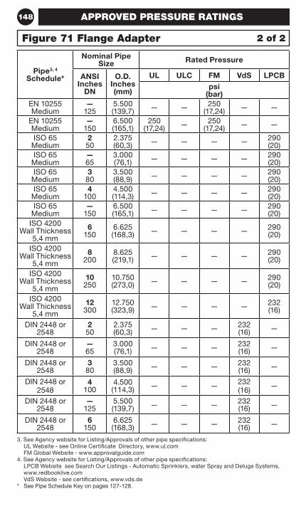
148
3. See Agency website for Listing/Approvals of other pipe specifications: UL Website - see Online Certificate Directory, www.ul.com FM Global Website - www.approvalguide.com
4. See Agency website for Listing/Approvals of other pipe specifications: LPCB Website see Search Our Listings - Automatic Sprinklers, water Spray and Deluge Systems, www.redbooklive.com VdS Website - see certifications, www.vds.de
* See Pipe Schedule Key on pages 127-128.
Pipe3, 4 Schedule*
Nominal Pipe Size Rated Pressure
ANSI Inches
DN
O.D. Inches (mm)
UL ULC FM VdS LPCBpsi
(bar)EN 10255 Medium
— 125
5.500 (139,7) — — 250
(17,24) — —
EN 10255 Medium
— 150
6.500 (165,1)
250 (17,24) — 250
(17,24) — —
ISO 65 Medium
2 50
2.375 (60,3) — — — — 290
(20)ISO 65
Medium— 65
3.000 (76,1) — — — — 290
(20)ISO 65
Medium3
803.500 (88,9) — — — — 290
(20)ISO 65
Medium4
1004.500 (114,3) — — — — 290
(20)ISO 65
Medium—
1506.500(165,1) — — — — 290
(20)ISO 4200
Wall Thickness 5,4 mm
6 150
6.625 (168,3) — — — — 290
(20)
ISO 4200 Wall Thickness
5,4 mm
8 200
8.625 (219,1) — — — — 290
(20)
ISO 4200 Wall Thickness
5,4 mm
10 250
10.750 (273,0) — — — — 290
(20)
ISO 4200 Wall Thickness
5,4 mm
12 300
12.750 (323,9) — — — — 232
(16)
DIN 2448 or 2548
2 50
2.375 (60,3) — — — 232
(16) —
DIN 2448 or 2548
— 65
3.000 (76,1) — — — 232
(16) —
DIN 2448 or 2548
3 80
3.500 (88,9) — — — 232
(16) —
DIN 2448 or 2548
4 100
4.500 (114,3) — — — 232
(16) —
DIN 2448 or 2548
— 125
5.500 (139,7) — — — 232
(16) —
DIN 2448 or 2548
6 150
6.625 (168,3) — — — 232
(16) —
2 of 2Figure 71 Flange Adapter
APPROVED PRESSURE RATINGS
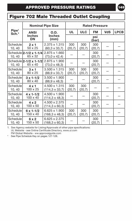
149
1. See Agency website for Listing/Approvals of other pipe specifications: UL Website - see Online Certificate Directory, www.ul.com FM Global Website - ww.approvalguide.com
* See Pipe Schedule Key on pages 127-128.
Pipe1 Sch.*
Nominal Pipe Size Rated Pressure
ANSI Inches
DN
O.D. Inches (mm)
UL ULC FM VdS LPCBpsi
(bar)Schedule
10, 402 x 1
50 x 252.375 x 1.315 (60,3 x 33,7)
300 (20,7)
300 (20,7)
300 (20,7) — —
Schedule 10, 40
2-1/2 x 1-1/4 65 x 32
2.875 x 1.660 (73,0 x 42,4) — — 300
(20,7) — —
Schedule 10, 40
2-1/2 x 1-1/2 65 x 40
2.875 x 1.900 (73,0 x 48,3) — — 300
(20,7) — —
Schedule 10, 40
3 x 1 80 x 25
3.500 x 1.315 (88,9 x 33,7)
300 (20,7)
300 (20,7)
300 (20,7) — —
Schedule 10, 40
3 x 1-1/2 80 x 40
3.500 x 1.900 (88,9 x 48,3) — — 300
(20,7) — —
Schedule 10, 40
4 x 1 100 x 25
4.500 x 1.315 (114,3 x 33,7)
300 (20,7)
300 (20,7) — — —
Schedule 10, 40
4 x 1-1/2 100 x 40
4.500 x 1.900 (114,3 x 48,3) — — 300
(20,7) — —
Schedule 10, 40
4 x 2 100 x 50
4.500 x 2.375 (114,3 x 60,3) — — 300
(20,7) — —
Schedule 10, 40
6 x 1-1/2 150 x 40
6.625 x 1.900 (168,3 x 48,3)
300 (20,7)
300 (20,7)
300 (20,7) — —
Schedule 10, 40
6 x 2 150 x 50
6.625 x 2.375 (168,3 x 60,3) — — 300
(20,7) — —
Figure 702 Male Threaded Outlet Coupling
APPROVED PRESSURE RATINGS
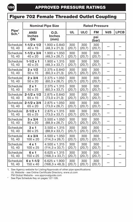
150
1. See Agency website for Listing/Approvals of other pipe specifications: UL Website - see Online Certificate Directory, www.ul.com FM Global Website - ww.approvalguide.com
* See Pipe Schedule Key on pages 127-128.
Pipe1 Sch.*
Nominal Pipe Size Rated Pressure
ANSI Inches
DN
O.D. Inches (mm)
UL ULC FM VdS LPCBpsi
(bar)Schedule
10, 401-1/2 x 1/2
40 x 151.900 x 0.840 (48,3 x 21,3)
300 (20,7)
300 (20,7)
300 (20,7) — —
Schedule 10, 40
1-1/2 x 3/4 40 x 20
1.900 x 1.050 (48,3 x 26,7)
300 (20,7)
300 (20,7)
300 (20,7) — —
Schedule 10, 40
1-1/2 x 1 40 x 25
1.900 x 1.315 (48,3 x 33,7)
300 (20,7)
300 (20,7)
300 (20,7) — —
Schedule 10, 40
2 x 1/2 50 x 15
2.375 x 0.840 (60,3 x 21,3)
300 (20,7)
300 (20,7)
300 (20,7) — —
Schedule 10, 40
2 x 3/4 50 x 20
2.375 x 1.050 (60,3 x 26,7)
300 (20,7)
300 (20,7)
300 (20,7) — —
Schedule 10, 40
2 x 1 50 x 25
2.375 x 1.315 (60,3 x 33,7)
300 (20,7)
300 (20,7)
300 (20,7) — —
Schedule 10, 40
2-1/2 x 1/2 65 x 15
2.875 x 0.840 (73,0 x 21,3)
300 (20,7)
300 (20,7)
300 (20,7) — —
Schedule 10, 40
2-1/2 x 3/4 65 x 20
2.875 x 1.050 (73,0 x 26,7)
300 (20,7)
300 (20,7)
300 (20,7) — —
Schedule 10, 40
2-1/2 x 1 65 x 25
2.875 x 1.315 (73,0 x 33,7)
300 (20,7)
300 (20,7)
300 (20,7) — —
Schedule 10, 40
3 x 3/4 80 x 20
3.500 x 1.050 (88,9 x 26,7)
300 (20,7)
300 (20,7)
300 (20,7) — —
Schedule 10, 40
3 x 1 80 x 25
3.500 x 1.315 (88,9 x 33,7)
300 (20,7)
300 (20,7)
300 (20,7) — —
Schedule 10, 40
4 x 3/4 100 x 20
4.500 x 1.050 (114,3 x 26,7)
300 (20,7)
300 (20,7)
300 (20,7) — —
Schedule 10, 40
4 x 1 100 x 25
4.500 x 1.315 (114,3 x 33,7)
300 (20,7)
300 (20,7)
300 (20,7) — —
Schedule 10, 40
6 x 1 150 x 25
6.625 x 1.315 (168,3 x 33,7)
300 (20,7)
300 (20,7)
300 (20,7) — —
Schedule 10, 40
6 x 1-1/2 150 x 40
6.625 x 1.900 (168,3 x 48,3)
300 (20,7)
300 (20,7)
300 (20,7) — —
Figure 702 Female Threaded Outlet Coupling
APPROVED PRESSURE RATINGS
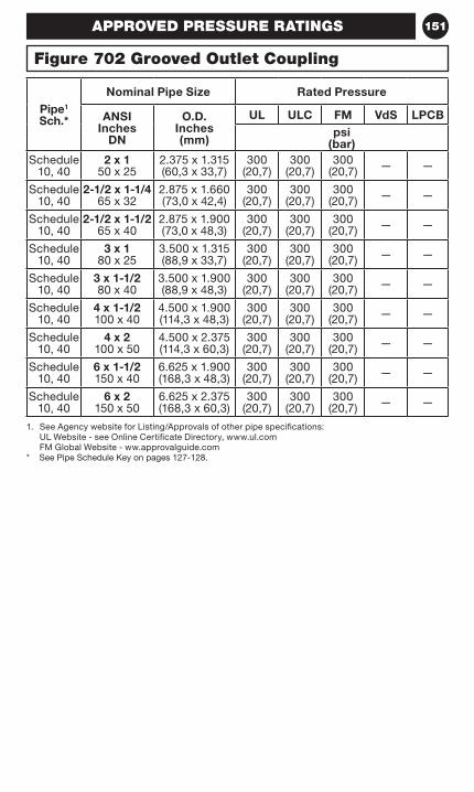
151
1. See Agency website for Listing/Approvals of other pipe specifications: UL Website - see Online Certificate Directory, www.ul.com FM Global Website - ww.approvalguide.com
* See Pipe Schedule Key on pages 127-128.
Pipe1 Sch.*
Nominal Pipe Size Rated Pressure
ANSI Inches
DN
O.D. Inches (mm)
UL ULC FM VdS LPCBpsi
(bar)Schedule
10, 402 x 1
50 x 252.375 x 1.315 (60,3 x 33,7)
300 (20,7)
300 (20,7)
300 (20,7) — —
Schedule 10, 40
2-1/2 x 1-1/4 65 x 32
2.875 x 1.660 (73,0 x 42,4)
300 (20,7)
300 (20,7)
300 (20,7) — —
Schedule 10, 40
2-1/2 x 1-1/2 65 x 40
2.875 x 1.900 (73,0 x 48,3)
300 (20,7)
300 (20,7)
300 (20,7) — —
Schedule 10, 40
3 x 1 80 x 25
3.500 x 1.315 (88,9 x 33,7)
300 (20,7)
300 (20,7)
300 (20,7) — —
Schedule 10, 40
3 x 1-1/2 80 x 40
3.500 x 1.900 (88,9 x 48,3)
300 (20,7)
300 (20,7)
300 (20,7) — —
Schedule 10, 40
4 x 1-1/2 100 x 40
4.500 x 1.900 (114,3 x 48,3)
300 (20,7)
300 (20,7)
300 (20,7) — —
Schedule 10, 40
4 x 2 100 x 50
4.500 x 2.375 (114,3 x 60,3)
300 (20,7)
300 (20,7)
300 (20,7) — —
Schedule 10, 40
6 x 1-1/2 150 x 40
6.625 x 1.900 (168,3 x 48,3)
300 (20,7)
300 (20,7)
300 (20,7) — —
Schedule 10, 40
6 x 2 150 x 50
6.625 x 2.375 (168,3 x 60,3)
300 (20,7)
300 (20,7)
300 (20,7) — —
APPROVED PRESSURE RATINGS
Figure 702 Grooved Outlet Coupling
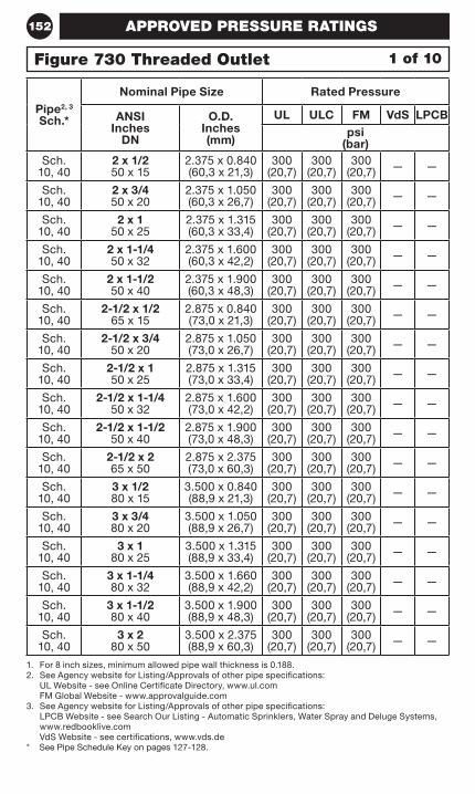
152
1. For 8 inch sizes, minimum allowed pipe wall thickness is 0.188.2. See Agency website for Listing/Approvals of other pipe specifications:
UL Website - see Online Certificate Directory, www.ul.com FM Global Website - www.approvalguide.com
3. See Agency website for Listing/Approvals of other pipe specifications: LPCB Website - see Search Our Listing - Automatic Sprinklers, Water Spray and Deluge Systems, www.redbooklive.com VdS Website - see certifications, www.vds.de
* See Pipe Schedule Key on pages 127-128.
Pipe2, 3 Sch.*
Nominal Pipe Size Rated Pressure
ANSI Inches
DN
O.D. Inches (mm)
UL ULC FM VdS LPCBpsi
(bar)Sch.
10, 402 x 1/2 50 x 15
2.375 x 0.840 (60,3 x 21,3)
300 (20,7)
300 (20,7)
300 (20,7) — —
Sch. 10, 40
2 x 3/4 50 x 20
2.375 x 1.050 (60,3 x 26,7)
300 (20,7)
300 (20,7)
300 (20,7) — —
Sch. 10, 40
2 x 1 50 x 25
2.375 x 1.315 (60,3 x 33,4)
300 (20,7)
300 (20,7)
300 (20,7) — —
Sch. 10, 40
2 x 1-1/4 50 x 32
2.375 x 1.600 (60,3 x 42,2)
300 (20,7)
300 (20,7)
300 (20,7) — —
Sch. 10, 40
2 x 1-1/2 50 x 40
2.375 x 1.900 (60,3 x 48,3)
300 (20,7)
300 (20,7)
300 (20,7) — —
Sch. 10, 40
2-1/2 x 1/2 65 x 15
2.875 x 0.840 (73,0 x 21,3)
300 (20,7)
300 (20,7)
300 (20,7) — —
Sch. 10, 40
2-1/2 x 3/4 50 x 20
2.875 x 1.050 (73,0 x 26,7)
300 (20,7)
300 (20,7)
300 (20,7) — —
Sch. 10, 40
2-1/2 x 1 50 x 25
2.875 x 1.315 (73,0 x 33,4)
300 (20,7)
300 (20,7)
300 (20,7) — —
Sch. 10, 40
2-1/2 x 1-1/4 50 x 32
2.875 x 1.600 (73,0 x 42,2)
300 (20,7)
300 (20,7)
300 (20,7) — —
Sch. 10, 40
2-1/2 x 1-1/2 50 x 40
2.875 x 1.900 (73,0 x 48,3)
300 (20,7)
300 (20,7)
300 (20,7) — —
Sch. 10, 40
2-1/2 x 2 65 x 50
2.875 x 2.375 (73,0 x 60,3)
300 (20,7)
300 (20,7)
300 (20,7) — —
Sch. 10, 40
3 x 1/2 80 x 15
3.500 x 0.840 (88,9 x 21,3)
300 (20,7)
300 (20,7)
300 (20,7) — —
Sch. 10, 40
3 x 3/4 80 x 20
3.500 x 1.050 (88,9 x 26,7)
300 (20,7)
300 (20,7)
300 (20,7) — —
Sch. 10, 40
3 x 1 80 x 25
3.500 x 1.315 (88,9 x 33,4)
300 (20,7)
300 (20,7)
300 (20,7) — —
Sch. 10, 40
3 x 1-1/4 80 x 32
3.500 x 1.660 (88,9 x 42,2)
300 (20,7)
300 (20,7)
300 (20,7) — —
Sch. 10, 40
3 x 1-1/2 80 x 40
3.500 x 1.900 (88,9 x 48,3)
300 (20,7)
300 (20,7)
300 (20,7) — —
Sch. 10, 40
3 x 2 80 x 50
3.500 x 2.375 (88,9 x 60,3)
300 (20,7)
300 (20,7)
300 (20,7) — —
1 of 10Figure 730 Threaded Outlet
APPROVED PRESSURE RATINGS
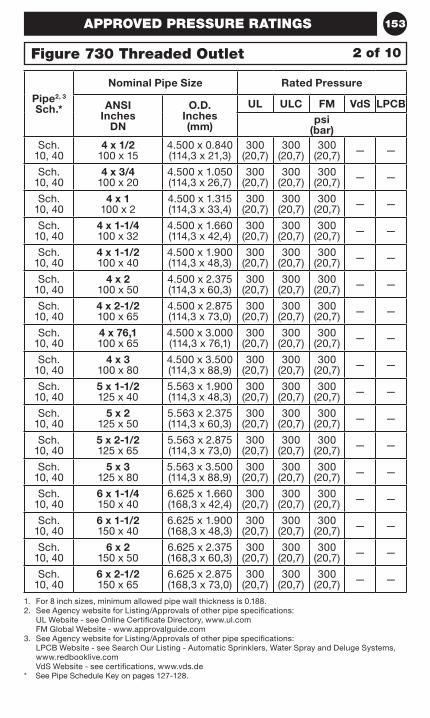
153
1. For 8 inch sizes, minimum allowed pipe wall thickness is 0.188.2. See Agency website for Listing/Approvals of other pipe specifications:
UL Website - see Online Certificate Directory, www.ul.com FM Global Website - www.approvalguide.com
3. See Agency website for Listing/Approvals of other pipe specifications: LPCB Website - see Search Our Listing - Automatic Sprinklers, Water Spray and Deluge Systems, www.redbooklive.com VdS Website - see certifications, www.vds.de
* See Pipe Schedule Key on pages 127-128.
Pipe2, 3 Sch.*
Nominal Pipe Size Rated Pressure
ANSI Inches
DN
O.D. Inches (mm)
UL ULC FM VdS LPCBpsi
(bar)Sch.
10, 404 x 1/2
100 x 154.500 x 0.840 (114,3 x 21,3)
300 (20,7)
300 (20,7)
300 (20,7) — —
Sch. 10, 40
4 x 3/4 100 x 20
4.500 x 1.050 (114,3 x 26,7)
300 (20,7)
300 (20,7)
300 (20,7) — —
Sch. 10, 40
4 x 1 100 x 2
4.500 x 1.315 (114,3 x 33,4)
300 (20,7)
300 (20,7)
300 (20,7) — —
Sch. 10, 40
4 x 1-1/4 100 x 32
4.500 x 1.660 (114,3 x 42,4)
300 (20,7)
300 (20,7)
300 (20,7) — —
Sch. 10, 40
4 x 1-1/2 100 x 40
4.500 x 1.900 (114,3 x 48,3)
300 (20,7)
300 (20,7)
300 (20,7) — —
Sch. 10, 40
4 x 2 100 x 50
4.500 x 2.375 (114,3 x 60,3)
300 (20,7)
300 (20,7)
300 (20,7) — —
Sch. 10, 40
4 x 2-1/2 100 x 65
4.500 x 2.875 (114,3 x 73,0)
300 (20,7)
300 (20,7)
300 (20,7) — —
Sch. 10, 40
4 x 76,1 100 x 65
4.500 x 3.000 (114,3 x 76,1)
300 (20,7)
300 (20,7)
300 (20,7) — —
Sch. 10, 40
4 x 3 100 x 80
4.500 x 3.500 (114,3 x 88,9)
300 (20,7)
300 (20,7)
300 (20,7) — —
Sch. 10, 40
5 x 1-1/2 125 x 40
5.563 x 1.900 (114,3 x 48,3)
300 (20,7)
300 (20,7)
300 (20,7) — —
Sch. 10, 40
5 x 2 125 x 50
5.563 x 2.375 (114,3 x 60,3)
300 (20,7)
300 (20,7)
300 (20,7) — —
Sch. 10, 40
5 x 2-1/2 125 x 65
5.563 x 2.875 (114,3 x 73,0)
300 (20,7)
300 (20,7)
300 (20,7) — —
Sch. 10, 40
5 x 3 125 x 80
5.563 x 3.500 (114,3 x 88,9)
300 (20,7)
300 (20,7)
300 (20,7) — —
Sch. 10, 40
6 x 1-1/4 150 x 40
6.625 x 1.660 (168,3 x 42,4)
300 (20,7)
300 (20,7)
300 (20,7) — —
Sch. 10, 40
6 x 1-1/2 150 x 40
6.625 x 1.900 (168,3 x 48,3)
300 (20,7)
300 (20,7)
300 (20,7) — —
Sch. 10, 40
6 x 2 150 x 50
6.625 x 2.375 (168,3 x 60,3)
300 (20,7)
300 (20,7)
300 (20,7) — —
Sch. 10, 40
6 x 2-1/2 150 x 65
6.625 x 2.875 (168,3 x 73,0)
300 (20,7)
300 (20,7)
300 (20,7) — —
2 of 10Figure 730 Threaded Outlet
APPROVED PRESSURE RATINGS
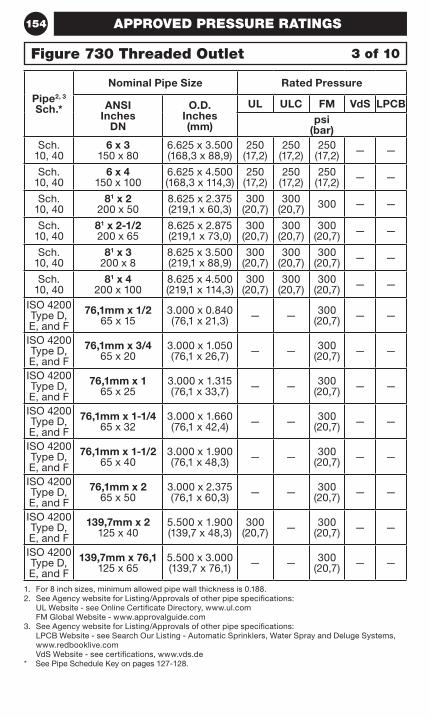
154
1. For 8 inch sizes, minimum allowed pipe wall thickness is 0.188.2. See Agency website for Listing/Approvals of other pipe specifications:
UL Website - see Online Certificate Directory, www.ul.com FM Global Website - www.approvalguide.com
3. See Agency website for Listing/Approvals of other pipe specifications: LPCB Website - see Search Our Listing - Automatic Sprinklers, Water Spray and Deluge Systems, www.redbooklive.com VdS Website - see certifications, www.vds.de
* See Pipe Schedule Key on pages 127-128.
Pipe2, 3 Sch.*
Nominal Pipe Size Rated Pressure
ANSI Inches
DN
O.D. Inches (mm)
UL ULC FM VdS LPCBpsi
(bar)Sch.
10, 406 x 3
150 x 806.625 x 3.500 (168,3 x 88,9)
250 (17,2)
250 (17,2)
250 (17,2) — —
Sch. 10, 40
6 x 4 150 x 100
6.625 x 4.500 (168,3 x 114,3)
250 (17,2)
250 (17,2)
250 (17,2) — —
Sch. 10, 40
81 x 2 200 x 50
8.625 x 2.375 (219,1 x 60,3)
300 (20,7)
300 (20,7) 300 — —
Sch. 10, 40
81 x 2-1/2 200 x 65
8.625 x 2.875 (219,1 x 73,0)
300 (20,7)
300 (20,7)
300 (20,7) — —
Sch. 10, 40
81 x 3 200 x 8
8.625 x 3.500 (219,1 x 88,9)
300 (20,7)
300 (20,7)
300 (20,7) — —
Sch. 10, 40
81 x 4 200 x 100
8.625 x 4.500 (219,1 x 114,3)
300 (20,7)
300 (20,7)
300 (20,7) — —
ISO 4200 Type D, E, and F
76,1mm x 1/2 65 x 15
3.000 x 0.840 (76,1 x 21,3) — — 300
(20,7) — —
ISO 4200 Type D, E, and F
76,1mm x 3/4 65 x 20
3.000 x 1.050 (76,1 x 26,7) — — 300
(20,7) — —
ISO 4200 Type D, E, and F
76,1mm x 1 65 x 25
3.000 x 1.315 (76,1 x 33,7) — — 300
(20,7) — —
ISO 4200 Type D, E, and F
76,1mm x 1-1/4 65 x 32
3.000 x 1.660 (76,1 x 42,4) — — 300
(20,7) — —
ISO 4200 Type D, E, and F
76,1mm x 1-1/2 65 x 40
3.000 x 1.900 (76,1 x 48,3) — — 300
(20,7) — —
ISO 4200 Type D, E, and F
76,1mm x 2 65 x 50
3.000 x 2.375 (76,1 x 60,3) — — 300
(20,7) — —
ISO 4200 Type D, E, and F
139,7mm x 2 125 x 40
5.500 x 1.900 (139,7 x 48,3)
300 (20,7) — 300
(20,7) — —
ISO 4200 Type D, E, and F
139,7mm x 76,1 125 x 65
5.500 x 3.000 (139,7 x 76,1) — — 300
(20,7) — —
3 of 10Figure 730 Threaded Outlet
APPROVED PRESSURE RATINGS
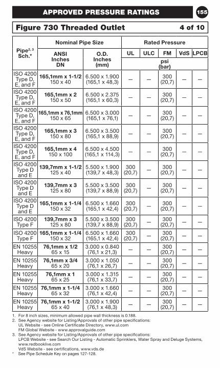
155
1. For 8 inch sizes, minimum allowed pipe wall thickness is 0.188.2. See Agency website for Listing/Approvals of other pipe specifications:
UL Website - see Online Certificate Directory, www.ul.com FM Global Website - www.approvalguide.com
3. See Agency website for Listing/Approvals of other pipe specifications: LPCB Website - see Search Our Listing - Automatic Sprinklers, Water Spray and Deluge Systems, www.redbooklive.com VdS Website - see certifications, www.vds.de
* See Pipe Schedule Key on pages 127-128.
Pipe2, 3 Sch.*
Nominal Pipe Size Rated Pressure
ANSI Inches
DN
O.D. Inches (mm)
UL ULC FM VdS LPCBpsi
(bar)ISO 4200 Type D, E, and F
165,1mm x 1-1/2 150 x 40
6.500 x 1.900 (165,1 x 48,3) — — 300
(20,7) — —
ISO 4200 Type D, E, and F
165,1mm x 2 150 x 50
6.500 x 2.375 (165,1 x 60,3) — — 300
(20,7) — —
ISO 4200 Type D, E, and F
165,1mm x 76,1mm 150 x 65
6.500 x 3.000 (165,1 x 76,1) — — 300
(20,7) — —
ISO 4200 Type D, E, and F
165,1mm x 3 150 x 80
6.500 x 3.500 (165,1 x 88,9) — — 300
(20,7) — —
ISO 4200 Type D, E, and F
165,1mm x 4 150 x 100
6.500 x 4.500 (165,1 x 114,3) — — 300
(20,7) — —
ISO 4200 Type D and E
139,7mm x 1-1/2 125 x 40
5.500 x 1.900 (139,7 x 48,3)
300 (20,7) — 300
(20,7) — —
ISO 4200 Type D and E
139,7mm x 3 125 x 80
5.500 x 3.500 (139,7 x 88,9)
300 (20,7) — 300
(20,7) — —
ISO 4200 Type D and E
165,1mm x 1-1/4 150 x 32
6.500 x 1.660 (165,1 x 42,4)
300 (20,7) — 300
(20,7) — —
ISO 4200 Type F
139,7mm x 3 125 x 80
5.500 x 3.500 (139,7 x 88,9)
300 (20,7) — 300
(20,7) — —
ISO 4200 Type F
165,1mm x 1-1/4 150 x 32
6.500 x 1.660 (165,1 x 42,4)
300 (20,7) — 300
(20,7) — —
EN 10255 Heavy
76,1mm x 1/2 65 x 15
3.000 x 0.840 (76,1 x 21,3) — — 300
(20,7) — —
EN 10255 Heavy
76,1mm x 3/4 65 x 20
3.000 x 1.050 (76,1 x 26,7) — — 300
(20,7) — —
EN 10255 Heavy
76,1mm x 1 65 x 25
3.000 x 1.315 (76,1 x 33,7) — — 300
(20,7) — —
EN 10255 Heavy
76,1mm x 1-1/4 65 x 32
3.000 x 1.660 (76,1 x 42,4) — — 300
(20,7) — —
EN 10255 Heavy
76,1mm x 1-1/2 65 x 40
3.000 x 1.900 (76,1 x 48,3) — — 300
(20,7) — —
4 of 10Figure 730 Threaded Outlet
APPROVED PRESSURE RATINGS
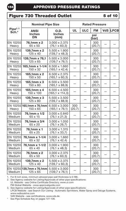
156
1. For 8 inch sizes, minimum allowed pipe wall thickness is 0.188.2. See Agency website for Listing/Approvals of other pipe specifications:
UL Website - see Online Certificate Directory, www.ul.com FM Global Website - www.approvalguide.com
3. See Agency website for Listing/Approvals of other pipe specifications: LPCB Website - see Search Our Listing - Automatic Sprinklers, Water Spray and Deluge Systems, www.redbooklive.com VdS Website - see certifications, www.vds.de
* See Pipe Schedule Key on pages 127-128.
Pipe2, 3 Sch.*
Nominal Pipe Size Rated Pressure
ANSI Inches
DN
O.D. Inches (mm)
UL ULC FM VdS LPCBpsi
(bar)EN 10255
Heavy76,1mm x 2
65 x 503.000 x 2.375 (76,1 x 60,3) — — 300
(20,7) — —
EN 10255 Heavy
139,7mm x 2 125 x 40
5.500 x 1.900 (139,7 x 48,3) — — 300
(20,7) — —
EN 10255 Heavy
139,7mm x 76,1 125 x 65
5.500 x 3.000 (139,7 x 76,1) — — 300
(20,7) — —
EN 10255 Heavy
165,1mm x 1-1/4 150 x 32
6.500 x 1.660 (165,1 x 42,4) — — 300
(20,7) — —
EN 10255 Heavy
165,1mm x 2 150 x 50
6.500 x 2.375 (165,1 x 60,3) — — 300
(20,7) — —
EN 10255 Heavy
165,1mm x 3 150 x 80
6.500 x 3.500 (165,1 x 88,9) — — 300
(20,7) — —
EN 10255 Heavy
165,1mm x 4 150 x 100
6.500 x 4.500 (165,1 x 114,3) — — 300
(20,7) — —
EN 10255 Heavy
139,7mm x 3 125 x 80
5.500 x 3.500 (139,7 x 88,9) — — 300
(20,7) — —
EN 10255 Heavy
165,1mm x 76,1mm 150 x 65
6.500 x 3.000 (165,1 x 76,1)
300 (20,7) — 300
(20,7) — —
EN 10255 Medium
76,1mm x 1/2 65 x 15
3.000 x 0.840 (76,1 x 21,3) — — 300
(20,7) — —
EN 10255 Medium
76,1mm x 3/4 65 x 20
3.000 x 1.050 (76,1 x 26,7) — — 300
(20,7) — —
EN 10255 Medium
76,1mm x 1 65 x 25
3.000 x 1.315 (76,1 x 33,7) — — 300
(20,7) — —
EN 10255 Medium
76,1mm x 1-1/4 65 x 32
3.000 x 1.660 (76,1 x 42,4) — — 300
(20,7) — —
EN 10255 Medium
76,1mm x 1-1/2 65 x 40
3.000 x 1.900 (76,1 x 48,3) — — 300
(20,7) — —
EN 10255 Medium
76,1mm x 2 65 x 50
3.000 x 2.375 (76,1 x 60,3) — — 300
(20,7) — —
EN 10255 Medium
139,7mm x 2 125 x 40
5.500 x 2.375 (139,7 x 60,3) — — 300
(20,7) — —
EN 10255 Medium
139,7mm x 76,1mm 125 x 65
5.500 x 3.000 (139,7 x 76,1) — — 300
(20,7) — —
5 of 10Figure 730 Threaded Outlet
APPROVED PRESSURE RATINGS
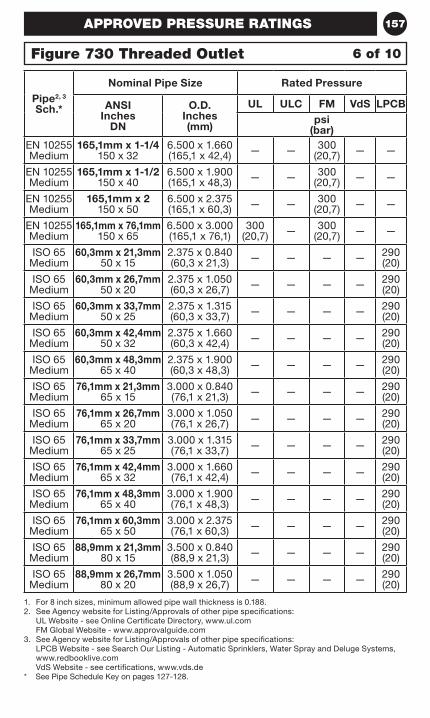
157
1. For 8 inch sizes, minimum allowed pipe wall thickness is 0.188.2. See Agency website for Listing/Approvals of other pipe specifications:
UL Website - see Online Certificate Directory, www.ul.com FM Global Website - www.approvalguide.com
3. See Agency website for Listing/Approvals of other pipe specifications: LPCB Website - see Search Our Listing - Automatic Sprinklers, Water Spray and Deluge Systems, www.redbooklive.com VdS Website - see certifications, www.vds.de
* See Pipe Schedule Key on pages 127-128.
Pipe2, 3 Sch.*
Nominal Pipe Size Rated Pressure
ANSI Inches
DN
O.D. Inches (mm)
UL ULC FM VdS LPCBpsi
(bar)EN 10255 Medium
165,1mm x 1-1/4 150 x 32
6.500 x 1.660 (165,1 x 42,4) — — 300
(20,7) — —
EN 10255 Medium
165,1mm x 1-1/2 150 x 40
6.500 x 1.900 (165,1 x 48,3) — — 300
(20,7) — —
EN 10255 Medium
165,1mm x 2 150 x 50
6.500 x 2.375 (165,1 x 60,3) — — 300
(20,7) — —
EN 10255 Medium
165,1mm x 76,1mm 150 x 65
6.500 x 3.000 (165,1 x 76,1)
300 (20,7) — 300
(20,7) — —
ISO 65 Medium
60,3mm x 21,3mm 50 x 15
2.375 x 0.840 (60,3 x 21,3) — — — — 290
(20)
ISO 65 Medium
60,3mm x 26,7mm 50 x 20
2.375 x 1.050 (60,3 x 26,7) — — — — 290
(20)
ISO 65 Medium
60,3mm x 33,7mm 50 x 25
2.375 x 1.315 (60,3 x 33,7) — — — — 290
(20)
ISO 65 Medium
60,3mm x 42,4mm 50 x 32
2.375 x 1.660 (60,3 x 42,4) — — — — 290
(20)
ISO 65 Medium
60,3mm x 48,3mm 65 x 40
2.375 x 1.900 (60,3 x 48,3) — — — — 290
(20)
ISO 65 Medium
76,1mm x 21,3mm 65 x 15
3.000 x 0.840 (76,1 x 21,3) — — — — 290
(20)
ISO 65 Medium
76,1mm x 26,7mm 65 x 20
3.000 x 1.050 (76,1 x 26,7) — — — — 290
(20)
ISO 65 Medium
76,1mm x 33,7mm 65 x 25
3.000 x 1.315 (76,1 x 33,7) — — — — 290
(20)
ISO 65 Medium
76,1mm x 42,4mm 65 x 32
3.000 x 1.660 (76,1 x 42,4) — — — — 290
(20)
ISO 65 Medium
76,1mm x 48,3mm 65 x 40
3.000 x 1.900 (76,1 x 48,3) — — — — 290
(20)
ISO 65 Medium
76,1mm x 60,3mm 65 x 50
3.000 x 2.375 (76,1 x 60,3) — — — — 290
(20)
ISO 65 Medium
88,9mm x 21,3mm 80 x 15
3.500 x 0.840 (88,9 x 21,3) — — — — 290
(20)
ISO 65 Medium
88,9mm x 26,7mm 80 x 20
3.500 x 1.050 (88,9 x 26,7) — — — — 290
(20)
6 of 10Figure 730 Threaded Outlet
APPROVED PRESSURE RATINGS
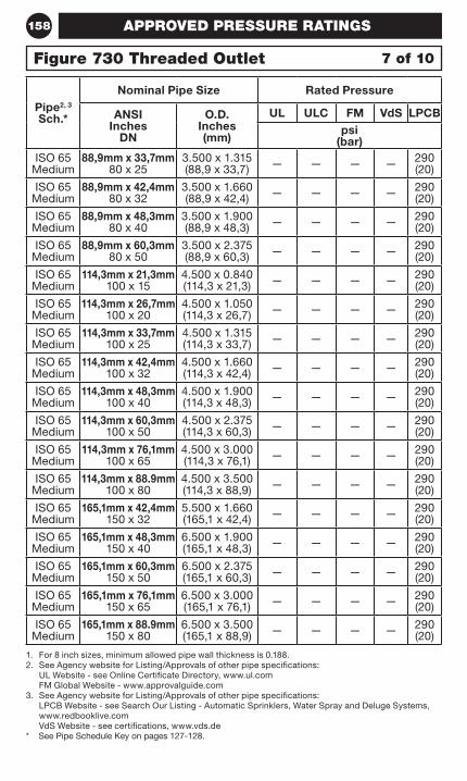
158
1. For 8 inch sizes, minimum allowed pipe wall thickness is 0.188.2. See Agency website for Listing/Approvals of other pipe specifications:
UL Website - see Online Certificate Directory, www.ul.com FM Global Website - www.approvalguide.com
3. See Agency website for Listing/Approvals of other pipe specifications: LPCB Website - see Search Our Listing - Automatic Sprinklers, Water Spray and Deluge Systems, www.redbooklive.com VdS Website - see certifications, www.vds.de
* See Pipe Schedule Key on pages 127-128.
Pipe2, 3 Sch.*
Nominal Pipe Size Rated Pressure
ANSI Inches
DN
O.D. Inches (mm)
UL ULC FM VdS LPCBpsi
(bar)ISO 65
Medium88,9mm x 33,7mm
80 x 253.500 x 1.315 (88,9 x 33,7) — — — — 290
(20)
ISO 65 Medium
88,9mm x 42,4mm 80 x 32
3.500 x 1.660 (88,9 x 42,4) — — — — 290
(20)
ISO 65 Medium
88,9mm x 48,3mm 80 x 40
3.500 x 1.900 (88,9 x 48,3) — — — — 290
(20)
ISO 65 Medium
88,9mm x 60,3mm 80 x 50
3.500 x 2.375 (88,9 x 60,3) — — — — 290
(20)
ISO 65 Medium
114,3mm x 21,3mm 100 x 15
4.500 x 0.840 (114,3 x 21,3) — — — — 290
(20)
ISO 65 Medium
114,3mm x 26,7mm 100 x 20
4.500 x 1.050 (114,3 x 26,7) — — — — 290
(20)
ISO 65 Medium
114,3mm x 33,7mm 100 x 25
4.500 x 1.315 (114,3 x 33,7) — — — — 290
(20)
ISO 65 Medium
114,3mm x 42,4mm 100 x 32
4.500 x 1.660 (114,3 x 42,4) — — — — 290
(20)
ISO 65 Medium
114,3mm x 48,3mm 100 x 40
4.500 x 1.900 (114,3 x 48,3) — — — — 290
(20)
ISO 65 Medium
114,3mm x 60,3mm 100 x 50
4.500 x 2.375 (114,3 x 60,3) — — — — 290
(20)
ISO 65 Medium
114,3mm x 76,1mm 100 x 65
4.500 x 3.000 (114,3 x 76,1) — — — — 290
(20)
ISO 65 Medium
114,3mm x 88.9mm 100 x 80
4.500 x 3.500 (114,3 x 88,9) — — — — 290
(20)
ISO 65 Medium
165,1mm x 42,4mm 150 x 32
5.500 x 1.660 (165,1 x 42,4) — — — — 290
(20)
ISO 65 Medium
165,1mm x 48,3mm 150 x 40
6.500 x 1.900 (165,1 x 48,3) — — — — 290
(20)
ISO 65 Medium
165,1mm x 60,3mm 150 x 50
6.500 x 2.375 (165,1 x 60,3) — — — — 290
(20)
ISO 65 Medium
165,1mm x 76,1mm 150 x 65
6.500 x 3.000 (165,1 x 76,1) — — — — 290
(20)
ISO 65 Medium
165,1mm x 88.9mm 150 x 80
6.500 x 3.500 (165,1 x 88,9) — — — — 290
(20)
7 of 10Figure 730 Threaded Outlet
APPROVED PRESSURE RATINGS
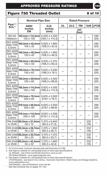
159
1. For 8 inch sizes, minimum allowed pipe wall thickness is 0.188.2. See Agency website for Listing/Approvals of other pipe specifications:
UL Website - see Online Certificate Directory, www.ul.com FM Global Website - www.approvalguide.com
3. See Agency website for Listing/Approvals of other pipe specifications: LPCB Website - see Search Our Listing - Automatic Sprinklers, Water Spray and Deluge Systems, www.redbooklive.com VdS Website - see certifications, www.vds.de
* See Pipe Schedule Key on pages 127-128.
Pipe2, 3 Sch.*
Nominal Pipe Size Rated Pressure
ANSI Inches
DN
O.D. Inches (mm)
UL ULC FM VdS LPCBpsi
(bar)ISO 65
Medium165,1mm x 114,3mm
150 x 1006.500 x 4.500 (165,1 x 114,3) — — — — 290
(20)ISO 4200 Wall THK 5,4mm
168,3mm x 42,4mm 150 x 32
6.625 x 1.660 (168,3 x 42,4) — — — — 290
(20)
ISO 4200 Wall THK 5,4mm
168,3mm x 48,3mm 150 x 40
6.625 x 1.900 (168,3 x 48,3) — — — — 290
(20)
ISO 4200 Wall THK 5,4mm
168,3mm x 60,3mm 150 x 50
6.625 x 2.375 (168,3 x 60,3) — — — — 290
(20)
ISO 4200 Wall THK 5,4mm
168,3mm x 76,1mm 150 x 65
6.625 x 3.000 (168,3 x 76,1) — — — — 290
(20)
ISO 4200 Wall THK 5,4mm
168,3mm x 88.9mm 150 x 80
6.625 x 3.500 (168,3 x 88,9) — — — — 290
(20)
ISO 4200 Wall THK 5,4mm
168,3mm x 114,3mm 150 x 100
6.625 x 4.500 (168,3 x 114,3) — — — — 290
(20)
ISO 4200 Wall THK 5,4mm
219,1mm x 76,1mm 200 x 65
8.625 x 3.000 (219,1 x 76,1) — — — — 290
(20)
ISO 4200 Wall THK 5,4mm
219,1mm x 88.9mm 200 x 80
8.625 x 3.500 (219,1 x 88,9) — — — — 290
(20)
ISO 4200 Wall THK 5,4mm
219,1mm x 114,3mm 200 x 100
8.625 x 4.500 (219,1 x 114,3) — — — — 290
(20)
DIN 2448 or 2548
60,3mm x 21,3mm 50 x 15
2.375 x 0.840 (60,3 x 21,3) — — — 232
(16) —
DIN 2448 or 2548
60,3mm x 26,7mm 50 x 20
2.375 x 1.050 (60,3 x 26,7) — — — 232
(16) —
DIN 2448 or 2548
60,3mm x 33,7mm 50 x 25
2.375 x 1.315 (60,3 x 33,7) — — — 232
(16) —
DIN 2448 or 2548
60,3mm x 42,4mm 50 x 32
2.375 x 1.660 (60,3 x 42,4) — — — 232
(16) —
8 of 10Figure 730 Threaded Outlet
APPROVED PRESSURE RATINGS
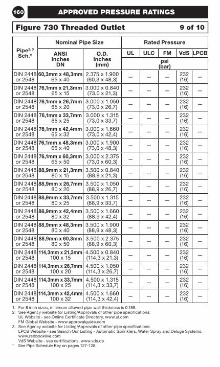
160
1. For 8 inch sizes, minimum allowed pipe wall thickness is 0.188.2. See Agency website for Listing/Approvals of other pipe specifications:
UL Website - see Online Certificate Directory, www.ul.com FM Global Website - www.approvalguide.com
3. See Agency website for Listing/Approvals of other pipe specifications: LPCB Website - see Search Our Listing - Automatic Sprinklers, Water Spray and Deluge Systems, www.redbooklive.com VdS Website - see certifications, www.vds.de
* See Pipe Schedule Key on pages 127-128.
Pipe2, 3 Sch.*
Nominal Pipe Size Rated Pressure
ANSI Inches
DN
O.D. Inches (mm)
UL ULC FM VdS LPCBpsi
(bar)DIN 2448 or 2548
60,3mm x 48,3mm 65 x 40
2.375 x 1.900 (60,3 x 48,3) — — — 232
(16) —
DIN 2448 or 2548
76,1mm x 21,3mm 65 x 15
3.000 x 0.840 (73,0 x 21,3) — — — 232
(16) —
DIN 2448 or 2548
76,1mm x 26,7mm 65 x 20
3.000 x 1.050 (73,0 x 26,7) — — — 232
(16) —
DIN 2448 or 2548
76,1mm x 33,7mm 65 x 25
3.000 x 1.315 (73,0 x 33,7) — — — 232
(16) —
DIN 2448 or 2548
76,1mm x 42,4mm 65 x 32
3.000 x 1.660 (73,0 x 42,4) — — — 232
(16) —
DIN 2448 or 2548
76,1mm x 48,3mm 65 x 40
3.000 x 1.900 (73,0 x 48,3) — — — 232
(16) —
DIN 2448 or 2548
76,1mm x 60,3mm 65 x 50
3.000 x 2.375 (73,0 x 60,3) — — — 232
(16) —
DIN 2448 or 2548
88,9mm x 21,3mm 80 x 15
3.500 x 0.840 (88,9 x 21,3) — — — 232
(16) —
DIN 2448 or 2548
88,9mm x 26,7mm 80 x 20
3.500 x 1.050 (88,9 x 26,7) — — — 232
(16) —
DIN 2448 or 2548
88,9mm x 33,7mm 80 x 25
3.500 x 1.315 (88,9 x 33,7) — — — 232
(16) —
DIN 2448 or 2548
88,9mm x 42,4mm 80 x 32
3.500 x 1.660 (88,9 x 42,4) — — — 232
(16) —
DIN 2448 or 2548
88,9mm x 48,3mm 80 x 40
3.500 x 1.900 (88,9 x 48,3) — — — 232
(16) —
DIN 2448 or 2548
88,9mm x 60,3mm 80 x 50
3.500 x 2.375 (88,9 x 60,3) — — — 232
(16) —
DIN 2448 or 2548
114,3mm x 21,3mm 100 x 15
4.500 x 0.840 (114,3 x 21,3) — — — 232
(16) —
DIN 2448 or 2548
114,3mm x 26,7mm 100 x 20
4.500 x 1.050 (114,3 x 26,7) — — — 232
(16) —
DIN 2448 or 2548
114,3mm x 33,7mm 100 x 25
4.500 x 1.315 (114,3 x 33,7) — — — 232
(16) —
DIN 2448 or 2548
114,3mm x 42,4mm 100 x 32
4.500 x 1.660 (114,3 x 42,4) — — — 232
(16) —
9 of 10Figure 730 Threaded Outlet
APPROVED PRESSURE RATINGS
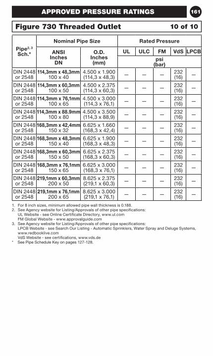
161
1. For 8 inch sizes, minimum allowed pipe wall thickness is 0.188.2. See Agency website for Listing/Approvals of other pipe specifications:
UL Website - see Online Certificate Directory, www.ul.com FM Global Website - www.approvalguide.com
3. See Agency website for Listing/Approvals of other pipe specifications: LPCB Website - see Search Our Listing - Automatic Sprinklers, Water Spray and Deluge Systems, www.redbooklive.com VdS Website - see certifications, www.vds.de
* See Pipe Schedule Key on pages 127-128.
Pipe2, 3 Sch.*
Nominal Pipe Size Rated Pressure
ANSI Inches
DN
O.D. Inches (mm)
UL ULC FM VdS LPCBpsi
(bar)DIN 2448 or 2548
114,3mm x 48,3mm 100 x 40
4.500 x 1.900 (114,3 x 48,3) — — — 232
(16) —
DIN 2448 or 2548
114,3mm x 60,3mm 100 x 50
4.500 x 2.375 (114,3 x 60,3) — — — 232
(16) —
DIN 2448 or 2548
114,3mm x 76,1mm 100 x 65
4.500 x 3.000 (114,3 x 76,1) — — — 232
(16) —
DIN 2448 or 2548
114,3mm x 88.9mm 100 x 80
4.500 x 3.500 (114,3 x 88,9) — — — 232
(16) —
DIN 2448 or 2548
168,3mm x 42,4mm 150 x 32
6.625 x 1.660 (168,3 x 42,4) — — — 232
(16) —
DIN 2448 or 2548
168,3mm x 48,3mm 150 x 40
6.625 x 1.900 (168,3 x 48,3) — — — 232
(16) —
DIN 2448 or 2548
168,3mm x 60,3mm 150 x 50
6.625 x 2.375 (168,3 x 60,3) — — — 232
(16) —
DIN 2448 or 2548
168,3mm x 76,1mm 150 x 65
6.625 x 3.000 (168,3 x 76,1) — — — 232
(16) —
DIN 2448 or 2548
219,1mm x 60,3mm 200 x 50
8.625 x 2.375 (219,1 x 60,3) — — — 232
(16) —
DIN 2448 or 2548
219,1mm x 76,1mm 200 x 65
8.625 x 3.000 (219,1 x 76,1) — — — 232
(16) —
APPROVED PRESSURE RATINGS
10 of 10Figure 730 Threaded Outlet
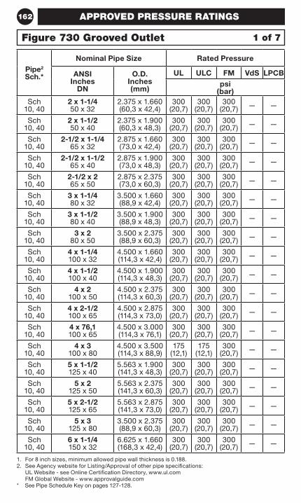
162
1. For 8 inch sizes, minimum allowed pipe wall thickness is 0.188.2. See Agency website for Listing/Approval of other pipe specifications:
UL Website - see Online Certification Directory, www.ul.com FM Global Website - www.approvalguide.com
* See Pipe Schedule Key on pages 127-128.
Pipe2 Sch.*
Nominal Pipe Size Rated Pressure
ANSI Inches
DN
O.D. Inches (mm)
UL ULC FM VdS LPCBpsi
(bar)Sch
10, 402 x 1-1/4 50 x 32
2.375 x 1.660 (60,3 x 42,4)
300 (20,7)
300 (20,7)
300 (20,7) — —
Sch 10, 40
2 x 1-1/2 50 x 40
2.375 x 1.900 (60,3 x 48,3)
300 (20,7)
300 (20,7)
300 (20,7) — —
Sch 10, 40
2-1/2 x 1-1/4 65 x 32
2.875 x 1.660 (73,0 x 42,4)
300 (20,7)
300 (20,7)
300 (20,7) — —
Sch 10, 40
2-1/2 x 1-1/2 65 x 40
2.875 x 1.900 (73,0 x 48,3)
300 (20,7)
300 (20,7)
300 (20,7) — —
Sch 10, 40
2-1/2 x 2 65 x 50
2.875 x 2.375 (73,0 x 60,3)
300 (20,7)
300 (20,7)
300 (20,7) — —
Sch 10, 40
3 x 1-1/4 80 x 32
3.500 x 1.660 (88,9 x 42,4)
300 (20,7)
300 (20,7)
300 (20,7) — —
Sch 10, 40
3 x 1-1/2 80 x 40
3.500 x 1.900 (88,9 x 48,3)
300 (20,7)
300 (20,7)
300 (20,7) — —
Sch 10, 40
3 x 2 80 x 50
3.500 x 2.375 (88,9 x 60,3)
300 (20,7)
300 (20,7)
300 (20,7) — —
Sch 10, 40
4 x 1-1/4 100 x 32
4.500 x 1.660 (114,3 x 42,4)
300 (20,7)
300 (20,7)
300 (20,7) — —
Sch 10, 40
4 x 1-1/2 100 x 40
4.500 x 1.900 (114,3 x 48,3)
300 (20,7)
300 (20,7)
300 (20,7) — —
Sch 10, 40
4 x 2 100 x 50
4.500 x 2.375 (114,3 x 60,3)
300 (20,7)
300 (20,7)
300 (20,7) — —
Sch 10, 40
4 x 2-1/2 100 x 65
4.500 x 2.875 (114,3 x 73,0)
300 (20,7)
300 (20,7)
300 (20,7) — —
Sch 10, 40
4 x 76,1 100 x 65
4.500 x 3.000 (114,3 x 76,1)
300 (20,7)
300 (20,7)
300 (20,7) — —
Sch 10, 40
4 x 3 100 x 80
4.500 x 3.500 (114,3 x 88,9)
175 (12,1)
175 (12,1)
300 (20,7) — —
Sch 10, 40
5 x 1-1/2 125 x 40
5.563 x 1.900 (141,3 x 48,3)
300 (20,7)
300 (20,7)
300 (20,7) — —
Sch 10, 40
5 x 2 125 x 50
5.563 x 2.375 (141,3 x 60,3)
300 (20,7)
300 (20,7)
300 (20,7) — —
Sch 10, 40
5 x 2-1/2 125 x 65
5.563 x 2.875 (141,3 x 73,0)
300 (20,7)
300 (20,7)
300 (20,7) — —
Sch 10, 40
5 x 3 125 x 80
3.500 x 2.375 (88,9 x 60,3)
300 (20,7)
300 (20,7)
300 (20,7) — —
Sch 10, 40
6 x 1-1/4 150 x 32
6.625 x 1.660 (168,3 x 42,4)
300 (20,7)
300 (20,7)
300 (20,7) — —
1 of 7Figure 730 Grooved Outlet
APPROVED PRESSURE RATINGS
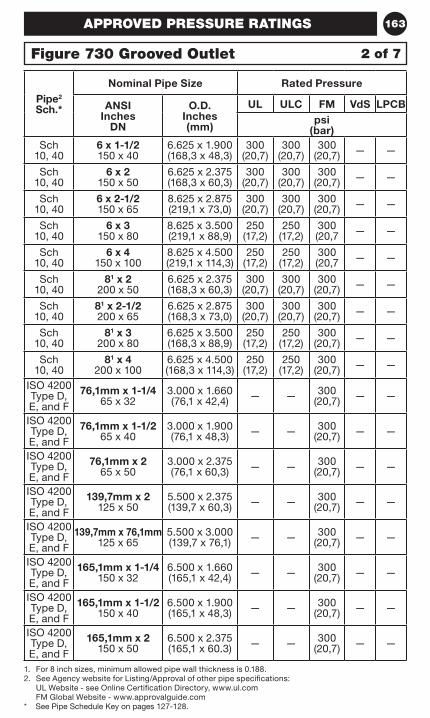
163
1. For 8 inch sizes, minimum allowed pipe wall thickness is 0.188.2. See Agency website for Listing/Approval of other pipe specifications:
UL Website - see Online Certification Directory, www.ul.com FM Global Website - www.approvalguide.com
* See Pipe Schedule Key on pages 127-128.
Pipe2 Sch.*
Nominal Pipe Size Rated Pressure
ANSI Inches
DN
O.D. Inches (mm)
UL ULC FM VdS LPCBpsi
(bar)Sch
10, 406 x 1-1/2 150 x 40
6.625 x 1.900 (168,3 x 48,3)
300 (20,7)
300 (20,7)
300 (20,7) — —
Sch 10, 40
6 x 2 150 x 50
6.625 x 2.375 (168,3 x 60,3)
300 (20,7)
300 (20,7)
300 (20,7) — —
Sch 10, 40
6 x 2-1/2 150 x 65
8.625 x 2.875 (219,1 x 73,0)
300 (20,7)
300 (20,7)
300 (20,7) — —
Sch 10, 40
6 x 3 150 x 80
8.625 x 3.500 (219,1 x 88,9)
250 (17,2)
250 (17,2)
300 (20,7 — —
Sch 10, 40
6 x 4 150 x 100
8.625 x 4.500 (219,1 x 114,3)
250 (17,2)
250 (17,2)
300 (20,7 — —
Sch 10, 40
81 x 2 200 x 50
6.625 x 2.375 (168,3 x 60,3)
300 (20,7)
300 (20,7)
300 (20,7) — —
Sch 10, 40
81 x 2-1/2 200 x 65
6.625 x 2.875 (168,3 x 73,0)
300 (20,7)
300 (20,7)
300 (20,7) — —
Sch 10, 40
81 x 3 200 x 80
6.625 x 3.500 (168,3 x 88,9)
250 (17,2)
250 (17,2)
300 (20,7) — —
Sch 10, 40
81 x 4 200 x 100
6.625 x 4.500 (168,3 x 114,3)
250 (17,2)
250 (17,2)
300 (20,7) — —
ISO 4200 Type D, E, and F
76,1mm x 1-1/4 65 x 32
3.000 x 1.660 (76,1 x 42,4) — — 300
(20,7) — —
ISO 4200 Type D, E, and F
76,1mm x 1-1/2 65 x 40
3.000 x 1.900 (76,1 x 48,3) — — 300
(20,7) — —
ISO 4200 Type D, E, and F
76,1mm x 2 65 x 50
3.000 x 2.375 (76,1 x 60,3) — — 300
(20,7) — —
ISO 4200 Type D, E, and F
139,7mm x 2 125 x 50
5.500 x 2.375 (139,7 x 60,3) — — 300
(20,7) — —
ISO 4200 Type D, E, and F
139,7mm x 76,1mm 125 x 65
5.500 x 3.000 (139,7 x 76,1) — — 300
(20,7) — —
ISO 4200 Type D, E, and F
165,1mm x 1-1/4 150 x 32
6.500 x 1.660 (165,1 x 42,4) — — 300
(20,7) — —
ISO 4200 Type D, E, and F
165,1mm x 1-1/2 150 x 40
6.500 x 1.900 (165,1 x 48,3) — — 300
(20,7) — —
ISO 4200 Type D, E, and F
165,1mm x 2 150 x 50
6.500 x 2.375 (165,1 x 60.3) — — 300
(20,7) — —
2 of 7Figure 730 Grooved Outlet
APPROVED PRESSURE RATINGS
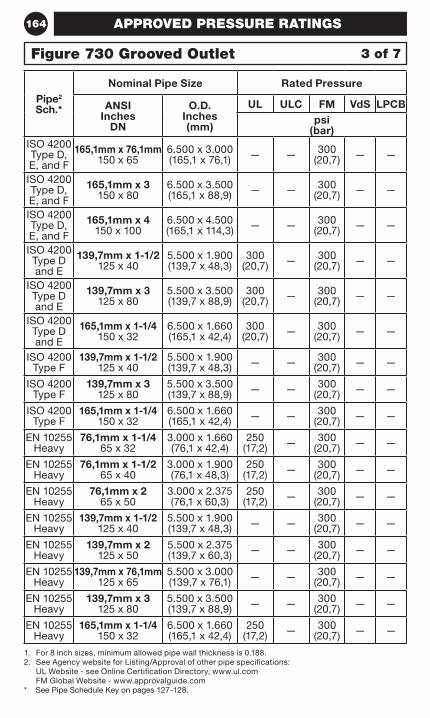
164
1. For 8 inch sizes, minimum allowed pipe wall thickness is 0.188.2. See Agency website for Listing/Approval of other pipe specifications:
UL Website - see Online Certification Directory, www.ul.com FM Global Website - www.approvalguide.com
* See Pipe Schedule Key on pages 127-128.
Pipe2 Sch.*
Nominal Pipe Size Rated Pressure
ANSI Inches
DN
O.D. Inches (mm)
UL ULC FM VdS LPCBpsi
(bar)ISO 4200 Type D, E, and F
165,1mm x 76,1mm 150 x 65
6.500 x 3.000 (165,1 x 76,1) — — 300
(20,7) — —
ISO 4200 Type D, E, and F
165,1mm x 3 150 x 80
6.500 x 3.500 (165,1 x 88,9) — — 300
(20,7) — —
ISO 4200 Type D, E, and F
165,1mm x 4 150 x 100
6.500 x 4.500 (165,1 x 114,3) — — 300
(20,7) — —
ISO 4200 Type D and E
139,7mm x 1-1/2 125 x 40
5.500 x 1.900 (139,7 x 48,3)
300 (20,7) — 300
(20,7) — —
ISO 4200 Type D and E
139,7mm x 3 125 x 80
5.500 x 3.500 (139,7 x 88,9)
300 (20,7) — 300
(20,7) — —
ISO 4200 Type D and E
165,1mm x 1-1/4 150 x 32
6.500 x 1.660 (165,1 x 42,4)
300 (20,7) — 300
(20,7) — —
ISO 4200 Type F
139,7mm x 1-1/2 125 x 40
5.500 x 1.900 (139,7 x 48,3) — — 300
(20,7) — —
ISO 4200 Type F
139,7mm x 3 125 x 80
5.500 x 3.500 (139,7 x 88,9) — — 300
(20,7) — —
ISO 4200 Type F
165,1mm x 1-1/4 150 x 32
6.500 x 1.660 (165,1 x 42,4) — — 300
(20,7) — —
EN 10255 Heavy
76,1mm x 1-1/4 65 x 32
3.000 x 1.660 (76,1 x 42,4)
250 (17,2) — 300
(20,7) — —
EN 10255 Heavy
76,1mm x 1-1/2 65 x 40
3.000 x 1.900 (76,1 x 48,3)
250 (17,2) — 300
(20,7) — —
EN 10255 Heavy
76,1mm x 2 65 x 50
3.000 x 2.375 (76,1 x 60,3)
250 (17,2) — 300
(20,7) — —
EN 10255 Heavy
139,7mm x 1-1/2 125 x 40
5.500 x 1.900 (139,7 x 48,3) — — 300
(20,7) — —
EN 10255 Heavy
139,7mm x 2 125 x 50
5.500 x 2.375 (139,7 x 60,3) — — 300
(20,7) — —
EN 10255 Heavy
139,7mm x 76,1mm 125 x 65
5.500 x 3.000 (139,7 x 76,1) — — 300
(20,7) — —
EN 10255 Heavy
139,7mm x 3 125 x 80
5.500 x 3.500 (139,7 x 88,9) — — 300
(20,7) — —
EN 10255 Heavy
165,1mm x 1-1/4 150 x 32
6.500 x 1.660 (165,1 x 42,4)
250 (17,2) — 300
(20,7) — —
3 of 7Figure 730 Grooved Outlet
APPROVED PRESSURE RATINGS
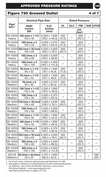
165
1. For 8 inch sizes, minimum allowed pipe wall thickness is 0.188.2. See Agency website for Listing/Approval of other pipe specifications:
UL Website - see Online Certification Directory, www.ul.com FM Global Website - www.approvalguide.com
* See Pipe Schedule Key on pages 127-128.
Pipe2 Sch.*
Nominal Pipe Size Rated Pressure
ANSI Inches
DN
O.D. Inches (mm)
UL ULC FM VdS LPCBpsi
(bar)EN 10255
Heavy165,1mm x 1-1/2
150 x 406.500 x 1.900 (165,1 x 48,3)
250 (17,2) — 300
(20,7) — —
EN 10255 Heavy
165,1mm x 2 150 x 50
6.500 x 2.375 (165,1 x 60.3)
250 (17,2) — 300
(20,7) — —
EN 10255 Heavy
165,1mm x 76,1mm 150 x 65
6.500 x 3.000 (165,1 x 76,1)
300 (20,7) — 300
(20,7) — —
EN 10255 Heavy
165,1mm x 3 150 x 80
6.500 x 3.500 (165,1 x 88,9) — — 300
(20,7) — —
EN 10255 Heavy
165,1mm x 4 150 x 100
6.500 x 4.500 (165,1 x 114,3) — — 300
(20,7) — —
EN 10255 Medium
76,1mm x 1-1/4 65 x 32
3.000 x 1.660 (76,1 x 42,4)
250 (17,2) — 300
(20,7) — —
EN 10255 Medium
76,1mm x 1-1/2 65 x 40
3.000 x 1.900 (76,1 x 48,3)
250 (17,2) — 300
(20,7) — —
EN 10255 Medium
76,1mm x 2 65 x 50
3.000 x 2.375 (76,1 x 60,3)
250 (17,2) — 300
(20,7) — —
EN 10255 Medium
139,7mm x 1-1/2 125 x 40
5.500 x 1.900 (139,7 x 48,3) — — 300
(20,7) — —
EN 10255 Medium
139,7mm x 2 125 x 50
5.500 x 2.375 (139,7 x 60,3) — — 300
(20,7) — —
EN 10255 Medium
139,7mm x 76,1mm 125 x 65
5.500 x 3.000 (139,7 x 76,1)
300 (20,7) — 300
(20,7) — —
EN 10255 Medium
139,7mm x 3 125 x 80
5.500 x 3.500 (139,7 x 88,9) — — 300
(20,7) — —
EN 10255 Medium
165,1mm x 1-1/4 150 x 32
6.500 x 1.660 (165,1 x 42,4)
250 (17,2) — 300
(20,7) — —
EN 10255 Medium
165,1mm x 1-1/2 150 x 40
6.500 x 1.900 (165,1 x 48,3)
250 (17,2) — 300
(20,7) — —
EN 10255 Medium
165,1mm x 2 150 x 50
6.500 x 2.375 (165,1 x 60.3)
250 (17,2) — 300
(20,7) — —
EN 10255 Medium
165,1mm x 76,1mm 150 x 65
6.500 x 3.000 (165,1 x 76,1)
300 (20,7) — 300
(20,7) — —
EN 10255 Medium
165,1mm x 3 150 x 80
6.500 x 3.500 (165,1 x 88,9) — — 300
(20,7) — —
EN 10255 Medium
165,1mm x 4 150 x 100
6.500 x 4.500 (165,1 x 114,3) — — 300
(20,7) — —
ISO 65 Medium
60,3mm x 42,4mm 50 x 32
2.375 x 1.600 (60,3 x 42,4) — — — — 290
(20)
4 of 7Figure 730 Grooved Outlet
APPROVED PRESSURE RATINGS
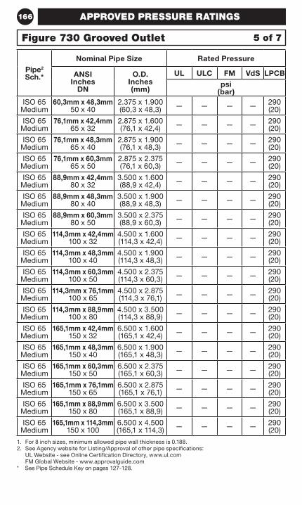
166
1. For 8 inch sizes, minimum allowed pipe wall thickness is 0.188.2. See Agency website for Listing/Approval of other pipe specifications:
UL Website - see Online Certification Directory, www.ul.com FM Global Website - www.approvalguide.com
* See Pipe Schedule Key on pages 127-128.
Pipe2 Sch.*
Nominal Pipe Size Rated Pressure
ANSI Inches
DN
O.D. Inches (mm)
UL ULC FM VdS LPCBpsi
(bar)ISO 65
Medium60,3mm x 48,3mm
50 x 402.375 x 1.900 (60,3 x 48,3) — — — — 290
(20)
ISO 65 Medium
76,1mm x 42,4mm 65 x 32
2.875 x 1.600 (76,1 x 42,4) — — — — 290
(20)
ISO 65 Medium
76,1mm x 48,3mm 65 x 40
2.875 x 1.900 (76,1 x 48,3) — — — — 290
(20)
ISO 65 Medium
76,1mm x 60,3mm 65 x 50
2.875 x 2.375 (76,1 x 60,3) — — — — 290
(20)
ISO 65 Medium
88,9mm x 42,4mm 80 x 32
3.500 x 1.600 (88,9 x 42,4) — — — — 290
(20)
ISO 65 Medium
88,9mm x 48,3mm 80 x 40
3.500 x 1.900 (88,9 x 48,3) — — — — 290
(20)
ISO 65 Medium
88,9mm x 60,3mm 80 x 50
3.500 x 2.375 (88,9 x 60,3) — — — — 290
(20)
ISO 65 Medium
114,3mm x 42,4mm 100 x 32
4.500 x 1.600 (114,3 x 42,4) — — — — 290
(20)
ISO 65 Medium
114,3mm x 48,3mm 100 x 40
4.500 x 1.900 (114,3 x 48,3) — — — — 290
(20)
ISO 65 Medium
114,3mm x 60,3mm 100 x 50
4.500 x 2.375 (114,3 x 60,3) — — — — 290
(20)
ISO 65 Medium
114,3mm x 76,1mm 100 x 65
4.500 x 2.875 (114,3 x 76,1) — — — — 290
(20)
ISO 65 Medium
114,3mm x 88,9mm 100 x 80
4.500 x 3.500 (114,3 x 88,9) — — — — 290
(20)
ISO 65 Medium
165,1mm x 42,4mm 150 x 32
6.500 x 1.600 (165,1 x 42,4) — — — — 290
(20)
ISO 65 Medium
165,1mm x 48,3mm 150 x 40
6.500 x 1.900 (165,1 x 48,3) — — — — 290
(20)
ISO 65 Medium
165,1mm x 60,3mm 150 x 50
6.500 x 2.375 (165,1 x 60,3) — — — — 290
(20)
ISO 65 Medium
165,1mm x 76,1mm 150 x 65
6.500 x 2.875 (165,1 x 76,1) — — — — 290
(20)
ISO 65 Medium
165,1mm x 88,9mm 150 x 80
6.500 x 3.500 (165,1 x 88,9) — — — — 290
(20)
ISO 65 Medium
165,1mm x 114,3mm 150 x 100
6.500 x 4.500 (165,1 x 114,3) — — — — 290
(20)
5 of 7Figure 730 Grooved Outlet
APPROVED PRESSURE RATINGS
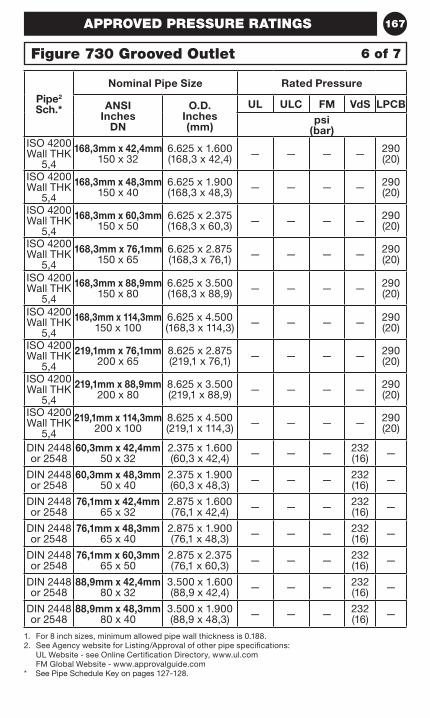
167
1. For 8 inch sizes, minimum allowed pipe wall thickness is 0.188.2. See Agency website for Listing/Approval of other pipe specifications:
UL Website - see Online Certification Directory, www.ul.com FM Global Website - www.approvalguide.com
* See Pipe Schedule Key on pages 127-128.
Pipe2 Sch.*
Nominal Pipe Size Rated Pressure
ANSI Inches
DN
O.D. Inches (mm)
UL ULC FM VdS LPCBpsi
(bar)ISO 4200 Wall THK
5,4
168,3mm x 42,4mm 150 x 32
6.625 x 1.600 (168,3 x 42,4) — — — — 290
(20)
ISO 4200 Wall THK
5,4
168,3mm x 48,3mm 150 x 40
6.625 x 1.900 (168,3 x 48,3) — — — — 290
(20)
ISO 4200 Wall THK
5,4
168,3mm x 60,3mm 150 x 50
6.625 x 2.375 (168,3 x 60,3) — — — — 290
(20)
ISO 4200 Wall THK
5,4
168,3mm x 76,1mm 150 x 65
6.625 x 2.875 (168,3 x 76,1) — — — — 290
(20)
ISO 4200 Wall THK
5,4
168,3mm x 88,9mm 150 x 80
6.625 x 3.500 (168,3 x 88,9) — — — — 290
(20)
ISO 4200 Wall THK
5,4
168,3mm x 114,3mm 150 x 100
6.625 x 4.500 (168,3 x 114,3) — — — — 290
(20)
ISO 4200 Wall THK
5,4
219,1mm x 76,1mm 200 x 65
8.625 x 2.875 (219,1 x 76,1) — — — — 290
(20)
ISO 4200 Wall THK
5,4
219,1mm x 88,9mm 200 x 80
8.625 x 3.500 (219,1 x 88,9) — — — — 290
(20)
ISO 4200 Wall THK
5,4
219,1mm x 114,3mm 200 x 100
8.625 x 4.500 (219,1 x 114,3) — — — — 290
(20)
DIN 2448 or 2548
60,3mm x 42,4mm 50 x 32
2.375 x 1.600 (60,3 x 42,4) — — — 232
(16) —
DIN 2448 or 2548
60,3mm x 48,3mm 50 x 40
2.375 x 1.900 (60,3 x 48,3) — — — 232
(16) —
DIN 2448 or 2548
76,1mm x 42,4mm 65 x 32
2.875 x 1.600 (76,1 x 42,4) — — — 232
(16) —
DIN 2448 or 2548
76,1mm x 48,3mm 65 x 40
2.875 x 1.900 (76,1 x 48,3) — — — 232
(16) —
DIN 2448 or 2548
76,1mm x 60,3mm 65 x 50
2.875 x 2.375 (76,1 x 60,3) — — — 232
(16) —
DIN 2448 or 2548
88,9mm x 42,4mm 80 x 32
3.500 x 1.600 (88,9 x 42,4) — — — 232
(16) —
DIN 2448 or 2548
88,9mm x 48,3mm 80 x 40
3.500 x 1.900 (88,9 x 48,3) — — — 232
(16) —
6 of 7Figure 730 Grooved Outlet
APPROVED PRESSURE RATINGS
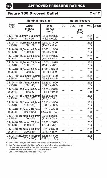
168
1. For 8 inch sizes, minimum allowed pipe wall thickness is 0.188.2. See Agency website for Listing/Approval of other pipe specifications:
UL Website - see Online Certification Directory, www.ul.com FM Global Website - www.approvalguide.com
* See Pipe Schedule Key on pages 127-128.
Pipe2 Sch.*
Nominal Pipe Size Rated Pressure
ANSI Inches
DN
O.D. Inches (mm)
UL ULC FM VdS LPCBpsi
(bar)DIN 2448 or 2548
88,9mm x 60,3mm 80 x 50
3.500 x 2.375 (88,9 x 60,3) — — — 232
(16) —
DIN 2448 or 2548
114,3mm x 42,4mm 100 x 32
4.500 x 1.600 (114,3 x 42,4) — — — 232
(16) —
DIN 2448 or 2548
114,3mm x 48,3mm 100 x 40
4.500 x 1.900 (114,3 x 48,3) — — — 232
(16) —
DIN 2448 or 2548
114,3mm x 60,3mm 100 x 50
4.500 x 2.375 (114,3 x 60,3) — — — 232
(16) —
DIN 2448 or 2548
114,3mm x 73,0mm 100 x 65
4.500 x 2.875 (114,3 x 76,1) — — — 232
(16) —
DIN 2448 or 2548
114,3mm x 88,9mm (100 x 80)
4.500 x 3.500 (114,3 x 88,9) — — — 232
(16) —
DIN 2448 or 2548
168,3mm x 42,4mm (150 x 32)
6.625 x 1.600 (168,3 x 42,4) — — — 232
(16) —
DIN 2448 or 2548
168,3mm x 48,3mm (150 x 40)
6.625 x 1.900 (168,3 x 48,3) — — — 232
(16) —
DIN 2448 or 2548
168,3mm x 60,3mm (150 x 50)
6.625 x 2.375 (168,3 x 60,3) — — — 232
(16) —
DIN 2448 or 2548
168,3mm x 76,1mm (150 x 65)
6.625 x 2.875 (168,3 x 76,1) — — — 232
(16) —
DIN 2448 or 2548
168,3mm x 88,9mm (150 x 80)
6.625 x 3.500 (168,3 x 88,9) — — — 232
(16) —
DIN 2448 or 2548
168,3mm x 114,3mm (150 x 100)
6.625 x 4.500 (168,3 x 114,3) — — — 232
(16) —
DIN 2448 or 2548
219,1mm x 60,3mm (200 x 50)
8.625 x 2.375 (219,1 x 60,3) — — — 232
(16) —
DIN 2448 or 2548
219,1mm x 76,1mm (200 x 65)
8.625 x 2.875 (219,1 x 76,1) — — — 232
(16) —
DIN 2448 or 2548
219,1mm x 88,9mm (200 x 80)
8.625 x 3.500 (219,1 x 88,9) — — — 232
(16) —
DIN 2448 or 2548
219,1mm x 114,3mm (200 x 100)
8.625 x 4.500 (219,1 x 114,3) — — — 232
(16) —
7 of 7Figure 730 Grooved Outlet
APPROVED PRESSURE RATINGS
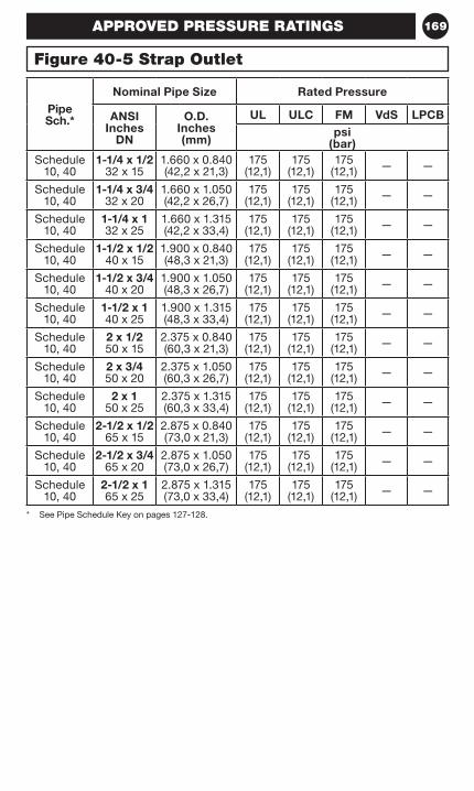
169
* See Pipe Schedule Key on pages 127-128.
Pipe Sch.*
Nominal Pipe Size Rated Pressure
ANSI Inches
DN
O.D. Inches (mm)
UL ULC FM VdS LPCBpsi
(bar)Schedule
10, 401-1/4 x 1/2
32 x 151.660 x 0.840 (42,2 x 21,3)
175 (12,1)
175 (12,1)
175 (12,1) — —
Schedule 10, 40
1-1/4 x 3/4 32 x 20
1.660 x 1.050 (42,2 x 26,7)
175 (12,1)
175 (12,1)
175 (12,1) — —
Schedule 10, 40
1-1/4 x 1 32 x 25
1.660 x 1.315 (42,2 x 33,4)
175 (12,1)
175 (12,1)
175 (12,1) — —
Schedule 10, 40
1-1/2 x 1/2 40 x 15
1.900 x 0.840 (48,3 x 21,3)
175 (12,1)
175 (12,1)
175 (12,1) — —
Schedule 10, 40
1-1/2 x 3/4 40 x 20
1.900 x 1.050 (48,3 x 26,7)
175 (12,1)
175 (12,1)
175 (12,1) — —
Schedule 10, 40
1-1/2 x 1 40 x 25
1.900 x 1.315 (48,3 x 33,4)
175 (12,1)
175 (12,1)
175 (12,1) — —
Schedule 10, 40
2 x 1/2 50 x 15
2.375 x 0.840 (60,3 x 21,3)
175 (12,1)
175 (12,1)
175 (12,1) — —
Schedule 10, 40
2 x 3/4 50 x 20
2.375 x 1.050 (60,3 x 26,7)
175 (12,1)
175 (12,1)
175 (12,1) — —
Schedule 10, 40
2 x 1 50 x 25
2.375 x 1.315 (60,3 x 33,4)
175 (12,1)
175 (12,1)
175 (12,1) — —
Schedule 10, 40
2-1/2 x 1/2 65 x 15
2.875 x 0.840 (73,0 x 21,3)
175 (12,1)
175 (12,1)
175 (12,1) — —
Schedule 10, 40
2-1/2 x 3/4 65 x 20
2.875 x 1.050 (73,0 x 26,7)
175 (12,1)
175 (12,1)
175 (12,1) — —
Schedule 10, 40
2-1/2 x 1 65 x 25
2.875 x 1.315 (73,0 x 33,4)
175 (12,1)
175 (12,1)
175 (12,1) — —
Figure 40-5 Strap Outlet
APPROVED PRESSURE RATINGS
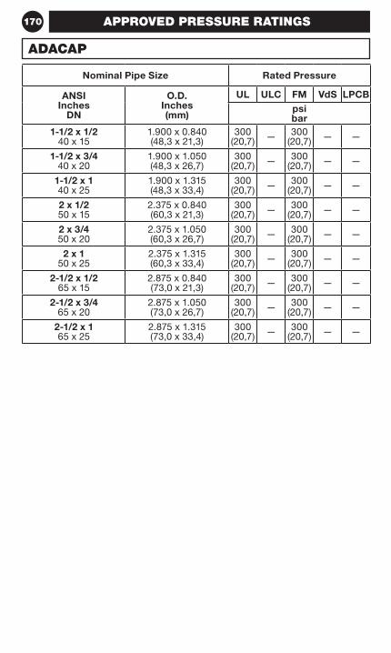
170
Nominal Pipe Size Rated Pressure
ANSI Inches
DN
O.D. Inches (mm)
UL ULC FM VdS LPCBpsi bar
1-1/2 x 1/2 40 x 15
1.900 x 0.840 (48,3 x 21,3)
300 (20,7) — 300
(20,7) — —
1-1/2 x 3/4 40 x 20
1.900 x 1.050 (48,3 x 26,7)
300 (20,7) — 300
(20,7) — —
1-1/2 x 1 40 x 25
1.900 x 1.315 (48,3 x 33,4)
300 (20,7) — 300
(20,7) — —
2 x 1/2 50 x 15
2.375 x 0.840 (60,3 x 21,3)
300 (20,7) — 300
(20,7) — —
2 x 3/4 50 x 20
2.375 x 1.050 (60,3 x 26,7)
300 (20,7) — 300
(20,7) — —
2 x 1 50 x 25
2.375 x 1.315 (60,3 x 33,4)
300 (20,7) — 300
(20,7) — —
2-1/2 x 1/2 65 x 15
2.875 x 0.840 (73,0 x 21,3)
300 (20,7) — 300
(20,7) — —
2-1/2 x 3/4 65 x 20
2.875 x 1.050 (73,0 x 26,7)
300 (20,7) — 300
(20,7) — —
2-1/2 x 1 65 x 25
2.875 x 1.315 (73,0 x 33,4)
300 (20,7) — 300
(20,7) — —
APPROVED PRESSURE RATINGS
ADACAP
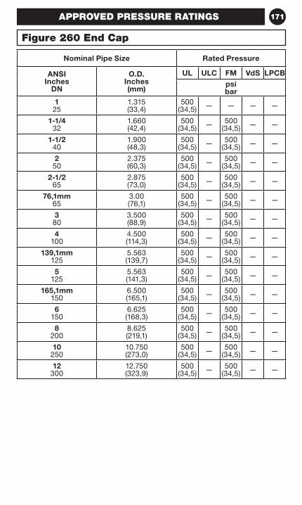
171
Nominal Pipe Size Rated Pressure
ANSI Inches
DN
O.D. Inches (mm)
UL ULC FM VdS LPCBpsi bar
1 25
1.315 (33,4)
500 (34,5) — — — —
1-1/4 32
1.660(42,4)
500 (34,5) — 500
(34,5) — —
1-1/2 40
1.900(48,3)
500 (34,5) — 500
(34,5) — —
2 50
2.375(60,3)
500 (34,5) — 500
(34,5) — —
2-1/2 65
2.875(73,0)
500 (34,5) — 500
(34,5) — —
76,1mm 65
3.00(76,1)
500 (34,5) — 500
(34,5) — —
3 80
3.500(88,9)
500 (34,5) — 500
(34,5) — —
4 100
4.500(114,3)
500 (34,5) — 500
(34,5) — —
139,1mm 125
5.563 (139,7)
500 (34,5) — 500
(34,5) — —
5 125
5.563 (141,3)
500 (34,5) — 500
(34,5) — —
165,1mm 150
6.500 (165,1)
500 (34,5) — 500
(34,5) — —
6 150
6.625 (168,3)
500 (34,5) — 500
(34,5) — —
8 200
8.625 (219,1)
500 (34,5) — 500
(34,5) — —
10 250
10.750(273,0)
500 (34,5) — 500
(34,5) — —
12 300
12.750(323,9)
500 (34,5) — 500
(34,5) — —
Figure 260 End Cap
APPROVED PRESSURE RATINGS
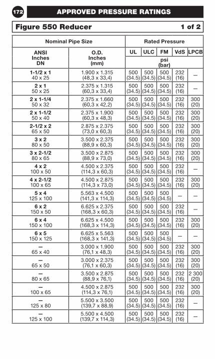
172
Nominal Pipe Size Rated Pressure
ANSI Inches
DN
O.D. Inches (mm)
UL ULC FM VdS LPCBpsi
(bar)1-1/2 x 1 40 x 25
1.900 x 1.315(48,3 x 33,4)
500 (34.5)
500 (34.5)
500 (34.5)
232 (16) —
2 x 1 50 x 25
2.375 x 1.315(60,3 x 33,4)
500 (34.5)
500 (34.5)
500 (34.5)
232 (16) —
2 x 1-1/4 50 x 32
2.375 x 1.660(60,3 x 42,2)
500 (34.5)
500 (34.5)
500 (34.5)
232 (16)
300 (20)
2 x 1-1/2 50 x 40
2.375 x 1.900(60,3 x 48,3)
500 (34.5)
500 (34.5)
500 (34.5)
232 (16)
300 (20)
2-1/2 x 2 65 x 50
2.875 x 2.375(73,0 x 60,3)
500 (34.5)
500 (34.5)
500 (34.5)
232 (16)
300 (20)
3 x 2 80 x 50
3.500 x 2.375(88,9 x 60,3)
500 (34.5)
500 (34.5)
500 (34.5)
232 (16)
300 (20)
3 x 2-1/2 80 x 65
3.500 x 2.875(88,9 x 73,0)
500 (34.5)
500 (34.5)
500 (34.5)
232 (16)
300 (20)
4 x 2 100 x 50
4.500 x 2.375(114,3 x 60,3)
500 (34.5)
500 (34.5)
500 (34.5)
232 (16) —
4 x 2-1/2 100 x 65
4.500 x 2.875(114,3 x 73,0)
500 (34.5)
500 (34.5)
500 (34.5)
232 (16)
300 (20)
5 x 4 125 x 100
5.563 x 4.500(141,3 x 114,3)
500 (34.5)
500 (34.5)
500 (34.5) — —
6 x 2 150 x 50
6.625 x 2.375(168,3 x 60,3)
500 (34.5)
500 (34.5)
500 (34.5)
232 (16) —
6 x 4 150 x 100
6.625 x 4.500(168,3 x 114,3)
500 (34.5)
500 (34.5)
500 (34.5)
232 (16)
300 (20)
6 x 5 150 x 125
6.625 x 5.563(168,3 x 141,3)
500 (34.5)
500 (34.5)
500 (34.5) — —
— 65 x 40
3.000 x 1.900(76,1 x 48,3)
500 (34.5)
500 (34.5)
500 (34.5)
232 (16)
300 (20)
— 65 x 50
3.000 x 2.375(76,1 x 60,3)
500 (34.5)
500 (34.5)
500 (34.5)
232 (16)
300 (20)
— 80 x 65
3.500 x 2.875(88,9 x 76,1)
500 (34.5)
500 (34.5)
500 (34.5)
232 (16)
2 300 (20)
— 100 x 65
4.500 x 2.875(114,3 x 76,1)
500 (34.5)
500 (34.5)
500 (34.5)
232 (16)
300 (20)
— 125 x 80
5.500 x 3.500(139,7 x 88,9)
500 (34.5)
500 (34.5)
500 (34.5)
232 (16) —
— 125 x 100
5.500 x 4.500(139,7 x 114,3)
500 (34.5)
500 (34.5)
500 (34.5)
232 (16) —
APPROVED PRESSURE RATINGS
Figure 550 Reducer 1 of 2
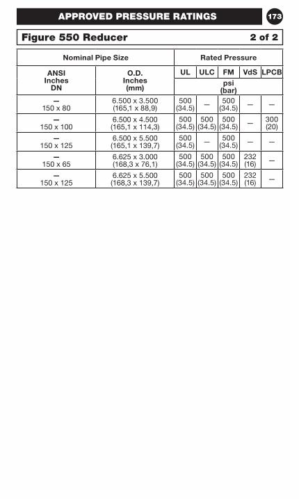
173
Nominal Pipe Size Rated Pressure
ANSI Inches
DN
O.D. Inches (mm)
UL ULC FM VdS LPCBpsi
(bar)—
150 x 806.500 x 3.500(165,1 x 88,9)
500 (34.5) — 500
(34.5) — —
— 150 x 100
6.500 x 4.500(165,1 x 114,3)
500 (34.5)
500 (34.5)
500 (34.5) — 300
(20)
— 150 x 125
6.500 x 5.500(165,1 x 139,7)
500 (34.5) — 500
(34.5) — —
— 150 x 65
6.625 x 3.000(168,3 x 76,1)
500 (34.5)
500 (34.5)
500 (34.5)
232 (16) —
— 150 x 125
6.625 x 5.500(168,3 x 139,7)
500 (34.5)
500 (34.5)
500 (34.5)
232 (16) —
APPROVED PRESSURE RATINGS
Figure 550 Reducer 2 of 2
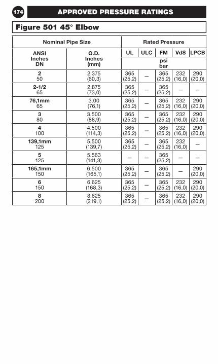
174
Nominal Pipe Size Rated Pressure
ANSI Inches
DN
O.D. Inches (mm)
UL ULC FM VdS LPCBpsi bar
2 50
2.375 (60,3)
365 (25,2) — 365
(25,2)232
(16,0)290
(20,0)
2-1/2 65
2.875 (73,0)
365 (25,2) — 365
(25,2) — —
76,1mm 65
3.00 (76,1)
365 (25,2) — 365
(25,2)232
(16,0)290
(20,0)
3 80
3.500 (88,9)
365 (25,2) — 365
(25,2)232
(16,0)290
(20,0)
4 100
4.500 (114,3)
365 (25,2) — 365
(25,2)232
(16,0)290
(20,0)
139,1mm 125
5.500 (139,7)
365 (25,2) — 365
(25,2)232
(16,0) —
5 125
5.563 (141,3) — — 365
(25,2) — —
165,1mm 150
6.500 (165,1)
365 (25,2) — 365
(25,2) — 290 (20,0)
6 150
6.625 (168,3)
365 (25,2) — 365
(25,2)232
(16,0)290
(20,0)
8 200
8.625 (219,1)
365 (25,2) — 365
(25,2)232
(16,0)290
(20,0)
Figure 501 45° Elbow
APPROVED PRESSURE RATINGS
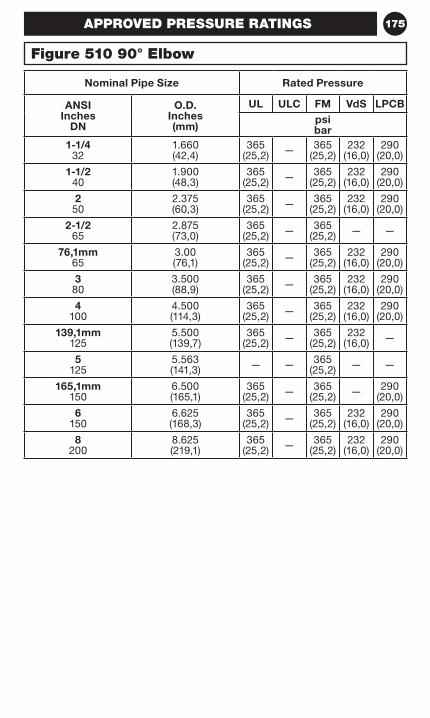
175
Nominal Pipe Size Rated Pressure
ANSI Inches
DN
O.D. Inches (mm)
UL ULC FM VdS LPCBpsi bar
1-1/4 32
1.660(42,4)
365 (25,2) — 365
(25,2)232
(16,0)290
(20,0)
1-1/2 40
1.900(48,3)
365 (25,2) — 365
(25,2)232
(16,0)290
(20,0)
2 50
2.375(60,3)
365 (25,2) — 365
(25,2)232
(16,0)290
(20,0)
2-1/2 65
2.875(73,0)
365 (25,2) — 365
(25,2) — —
76,1mm 65
3.00(76,1)
365 (25,2) — 365
(25,2)232
(16,0)290
(20,0)
3 80
3.500(88,9)
365 (25,2) — 365
(25,2)232
(16,0)290
(20,0)
4 100
4.500(114,3)
365 (25,2) — 365
(25,2)232
(16,0)290
(20,0)
139,1mm 125
5.500 (139,7)
365 (25,2) — 365
(25,2)232
(16,0) —
5 125
5.563 (141,3) — — 365
(25,2) — —
165,1mm 150
6.500 (165,1)
365 (25,2) — 365
(25,2) — 290 (20,0)
6 150
6.625 (168,3)
365 (25,2) — 365
(25,2)232
(16,0)290
(20,0)
8 200
8.625 (219,1)
365 (25,2) — 365
(25,2)232
(16,0)290
(20,0)
APPROVED PRESSURE RATINGS
Figure 510 90° Elbow
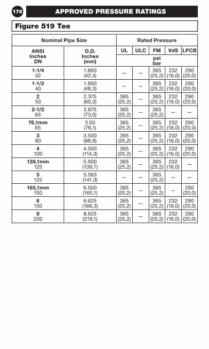
176
Nominal Pipe Size Rated Pressure
ANSI Inches
DN
O.D. Inches (mm)
UL ULC FM VdS LPCBpsi bar
1-1/4 32
1.660(42,4) — — 365
(25,2)232
(16,0)290
(20,0)
1-1/2 40
1.900(48,3) — — 365
(25,2)232
(16,0)290
(20,0)
2 50
2.375(60,3)
365 (25,2) — 365
(25,2)232
(16,0)290
(20,0)
2-1/2 65
2.875(73,0)
365 (25,2) — 365
(25,2) — —
76,1mm 65
3.00(76,1)
365 (25,2) — 365
(25,2)232
(16,0)290
(20,0)
3 80
3.500(88,9)
365 (25,2) — 365
(25,2)232
(16,0)290
(20,0)
4 100
4.500(114,3)
365 (25,2) — 365
(25,2)232
(16,0)290
(20,0)
139,1mm 125
5.500 (139,7)
365 (25,2) — 365
(25,2)232
(16,0) —
5 125
5.563 (141,3) — — 365
(25,2) — —
165,1mm 150
6.500 (165,1)
365 (25,2) — 365
(25,2) — 290 (20,0)
6 150
6.625 (168,3)
365 (25,2) — 365
(25,2)232
(16,0)290
(20,0)
8 200
8.625 (219,1)
365 (25,2) — 365
(25,2)232
(16,0)290
(20,0)
Figure 519 Tee
APPROVED PRESSURE RATINGS
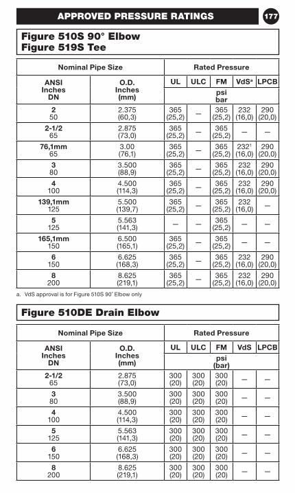
177
a. VdS approval is for Figure 510S 90˚ Elbow only
Nominal Pipe Size Rated Pressure
ANSI Inches
DN
O.D. Inches (mm)
UL ULC FM VdSa LPCBpsi bar
2 50
2.375(60,3)
365 (25,2) — 365
(25,2)232
(16,0)290
(20,0)
2-1/2 65
2.875(73,0)
365 (25,2) — 365
(25,2) — —
76,1mm 65
3.00(76,1)
365 (25,2) — 365
(25,2)2321 (16,0)
290 (20,0)
3 80
3.500(88,9)
365 (25,2) — 365
(25,2)232
(16,0)290
(20,0)
4 100
4.500(114,3)
365 (25,2) — 365
(25,2)232
(16,0)290
(20,0)
139,1mm 125
5.500 (139,7)
365 (25,2) — 365
(25,2)232
(16,0) —
5 125
5.563 (141,3) — — 365
(25,2) — —
165,1mm 150
6.500 (165,1)
365 (25,2) — 365
(25,2) — —
6 150
6.625 (168,3)
365 (25,2) — 365
(25,2)232
(16,0)290
(20,0)
8 200
8.625 (219,1)
365 (25,2) — 365
(25,2)232
(16,0)290
(20,0)
Nominal Pipe Size Rated Pressure
ANSI Inches
DN
O.D. Inches (mm)
UL ULC FM VdS LPCBpsi
(bar)2-1/2
652.875 (73,0)
300 (20)
300 (20)
300 (20) — —
3 80
3.500 (88,9)
300 (20)
300 (20)
300 (20) — —
4 100
4.500 (114,3)
300 (20)
300 (20)
300 (20) — —
5 125
5.563 (141,3)
300 (20)
300 (20)
300 (20) — —
6 150
6.625 (168,3)
300 (20)
300 (20)
300 (20) — —
8 200
8.625 (219,1)
300 (20)
300 (20)
300 (20) — —
APPROVED PRESSURE RATINGS
Figure 510S 90° ElbowFigure 519S Tee
Figure 510DE Drain Elbow
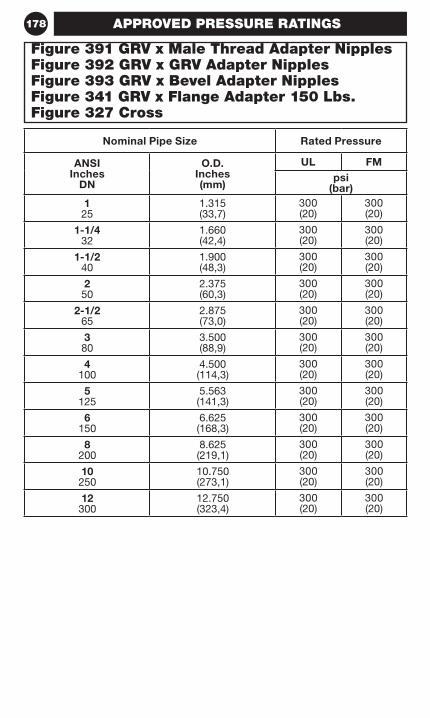
178
Nominal Pipe Size Rated Pressure
ANSI Inches
DN
O.D. Inches (mm)
UL FMpsi
(bar)1 25
1.315 (33,7)
300 (20)
300 (20)
1-1/4 32
1.660 (42,4)
300 (20)
300 (20)
1-1/2 40
1.900 (48,3)
300 (20)
300 (20)
2 50
2.375 (60,3)
300 (20)
300 (20)
2-1/2 65
2.875 (73,0)
300 (20)
300 (20)
3 80
3.500 (88,9)
300 (20)
300 (20)
4 100
4.500 (114,3)
300 (20)
300 (20)
5 125
5.563 (141,3)
300 (20)
300 (20)
6 150
6.625 (168,3)
300 (20)
300 (20)
8 200
8.625 (219,1)
300 (20)
300 (20)
10 250
10.750 (273,1)
300 (20)
300 (20)
12 300
12.750 (323,4)
300 (20)
300 (20)
APPROVED PRESSURE RATINGS
Figure 391 GRV x Male Thread Adapter NipplesFigure 392 GRV x GRV Adapter NipplesFigure 393 GRV x Bevel Adapter NipplesFigure 341 GRV x Flange Adapter 150 Lbs.Figure 327 Cross
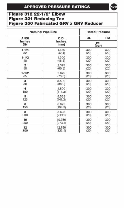
179
Nominal Pipe Size Rated Pressure
ANSI Inches
DN
O.D. Inches (mm)
UL FMpsi
(bar)1-1/4
321.660 (42,4)
300 (20)
300 (20)
1-1/2 40
1.900 (48,3)
300 (20)
300 (20)
2 50
2.375 (60,3)
300 (20)
300 (20)
2-1/2 65
2.875 (73,0)
300 (20)
300 (20)
3 80
3.500 (88,9)
300 (20)
300 (20)
4 100
4.500 (114,3)
300 (20)
300 (20)
5 125
5.563 (141,3)
300 (20)
300 (20)
6 150
6.625 (168,3)
300 (20)
300 (20)
8 200
8.625 (219,1)
300 (20)
300 (20)
10 250
10.750 (273,1)
300 (20)
300 (20)
12 300
12.750 (323,4)
300 (20)
300 (20)
APPROVED PRESSURE RATINGS
Figure 312 22-1/2° ElbowFigure 321 Reducing TeeFigure 350 Fabricated GRV x GRV Reducer
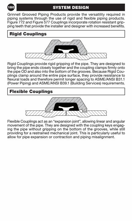
180 SYSTEM DESIGN
Rigid Couplings provide rigid gripping of the pipe. They are designed to bring the pipe ends closely together and the coupling clamps firmly onto the pipe OD and also into the bottom of the grooves. Because Rigid Cou-plings clamp around the entire pipe surface, they provide resistance to flexural loads and therefore permit longer spacing to ASME/ANSI B31.1 (Power Piping) and ASME/ANSI B39.1 (Building Services) requirements.
Grinnell Grooved Piping Products provide the versatility required in piping systems through the use of rigid and flexible piping products. Figure 772 and Figure 577 Couplings incorporate rotation resistant grip-ping teeth that provide the installer and designer with increased benefits.
Flexible Couplings act as an “expansion joint”, allowing linear and angular movement of the pipe. They are designed with the coupling keys engag-ing the pipe without gripping on the bottom of the grooves, while still providing for a restrained mechanical joint. This is particularly useful to allow for pipe expansion or contraction and piping misalignment.
Rigid Couplings
Flexible Couplings
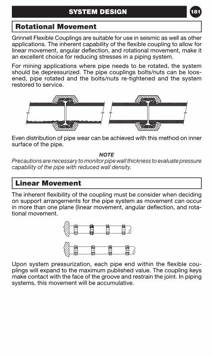
181SYSTEM DESIGN
Grinnell Flexible Couplings are suitable for use in seismic as well as other applications. The inherent capability of the flexible coupling to allow for linear movement, angular deflection, and rotational movement, make it an excellent choice for reducing stresses in a piping system.
For mining applications where pipe needs to be rotated, the system should be depressurized. The pipe couplings bolts/nuts can be loos-ened, pipe rotated and the bolts/nuts re-tightened and the system restored to service.
Even distribution of pipe wear can be achieved with this method on inner surface of the pipe.
NOTEPrecautions are necessary to monitor pipe wall thickness to evaluate pressure capability of the pipe with reduced wall density.
The inherent flexibility of the coupling must be consider when deciding on support arrangements for the pipe system as movement can occur in more than one plane (linear movement, angular deflection, and rota-tional movement.
Upon system pressurization, each pipe end within the flexible cou-plings will expand to the maximum published value. The coupling keys make contact with the face of the groove and restrain the joint. In piping systems, this movement will be accumulative.
Rotational Movement
Linear Movement
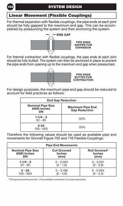
182 SYSTEM DESIGN
For thermal expansion with flexible couplings, the pipe ends at each joint should be fully gapped to the maximum end gap. This can be accom-plished by pressurizing the system and then anchoring the system.
For thermal contraction with flexible couplings, the pipe ends at each joint should be fully butted. The system can then be anchored in place to prevent the pipe ends from opening up to the maximum end gap when pressurized.
For design purposes, the maximum pipe end gap should be reduced to account for field practices as follows:
Therefore the following values should be used as available pipe end movements for Grinnell Figure 705 and 716 Flexible Couplings:
End Gap Reduction
Nominal Pipe Size ANSI Inches
DN
Maximum Pipe End Gap Reduction
1-1/4 - 3 32 - 80 50%
4-24 100 - 600 25%
Pipe End Movements
Nominal Pipe Size ANSI Inches
DN
Cut Grooved Inches (mm)
Roll Grooved* Inches (mm)
1-1/4 - 3 32 - 80
0 - 0.063 (0 - 1,6)
0 - 0.031 (0 - 0,8)
4 - 24 100 - 600
0 - 0.188 (0 - 4,8)
0 - 0.094 (0 - 2,4)
* Roll grooved joints provide 1/2 the available movement of cut grooved joints.
Linear Movement (Flexible Couplings)
PIPE ENDS GAPPED FOR EXPANSION
PIPE ENDS BUTTED FOR
CONTRACTION
END GAP
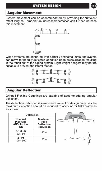
183SYSTEM DESIGN
System movement can be accommodated by providing for sufficient offset lengths. Temperature increases/decreases can further increase this movement.
Grinnell Flexible Couplings are capable of accommodating angular deflection.
The deflection published is a maximum value. For design purposes the maximum deflection should be reduced to account for field practices as shown:
When systems are anchored with partially deflected joints, the system can move to the fully deflected condition upon pressurization resulting in the “snaking” of the piping system. Light weight hangers may not be suitable to prevent the lateral motion.
Deflection
Nominal Pipe Size
ANSI Inches DN
Maximum Pipe
Deflection Reduction
1-1/4 - 3 32 - 80 50%
4 - 24 100 - 600 25%
Angular Movement
Angular Deflection
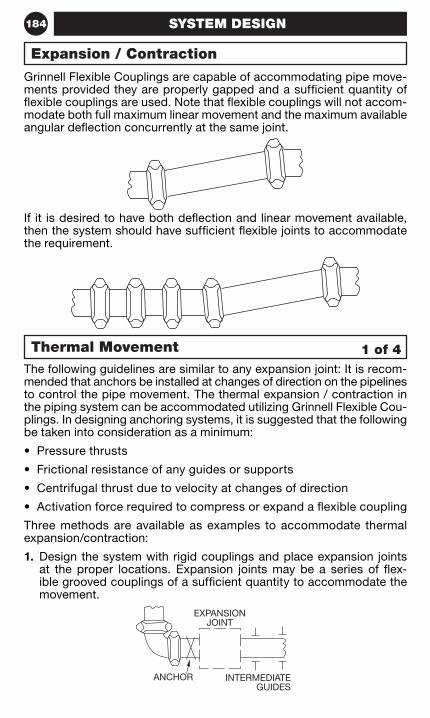
184 SYSTEM DESIGN
Grinnell Flexible Couplings are capable of accommodating pipe move-ments provided they are properly gapped and a sufficient quantity of flexible couplings are used. Note that flexible couplings will not accom-modate both full maximum linear movement and the maximum available angular deflection concurrently at the same joint.
If it is desired to have both deflection and linear movement available, then the system should have sufficient flexible joints to accommodate the requirement.
The following guidelines are similar to any expansion joint: It is recom-mended that anchors be installed at changes of direction on the pipelines to control the pipe movement. The thermal expansion / contraction in the piping system can be accommodated utilizing Grinnell Flexible Cou-plings. In designing anchoring systems, it is suggested that the following be taken into consideration as a minimum:
• Pressure thrusts
• Frictional resistance of any guides or supports
• Centrifugal thrust due to velocity at changes of direction
• Activation force required to compress or expand a flexible coupling
Three methods are available as examples to accommodate thermal expansion/contraction:
1. Design the system with rigid couplings and place expansion joints at the proper locations. Expansion joints may be a series of flex-ible grooved couplings of a sufficient quantity to accommodate the movement.
Expansion / Contraction
1 of 4Thermal Movement
EXPANSIONJOINT
INTERMEDIATEGUIDES
ANCHOR
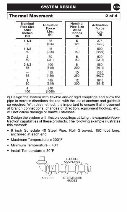
185SYSTEM DESIGN
2) Design the system with flexible and/or rigid couplings and allow the pipe to move in directions desired, with the use of anchors and guides if so required. With this method, it is important to ensure that movement at branch connections, changes of direction, equipment hookup, etc., will not cause damage or harmful stresses.
3) Design the system with flexible couplings utilizing the expansion/con-traction capabilities of these products. The following example illustrates this method:
• 6 inch Schedule 40 Steel Pipe, Roll Grooved, 150 foot long, anchored at each end.
• Maximum Temperature = 200°F
• Minimum Temperature = 40°F
• Install Temperature = 80°F
Nominal Pipe Size
ANSI Inches
DN
Activation Force Lbs. (N)
Nominal Pipe Size
ANSI Inches
DN
Activation Force Lbs. (N)
1-1/4 32
35 (156)
5125
375 (1668)
1-1/2 50
45 (200)
– 150
500 (2224)
250
70 (311)
6150
520 (2313)
2-1/2 65
100 (645)
8200
880 (3914)
— 65
110 (489)
10250
1365(6072)
380
145 (645)
12300
1915(8518)
4100
240 (1068)
Thermal Movement 2 of 4
FLEXIBLECOUPLINGS
INTERMEDIATEGUIDES
ANCHOR
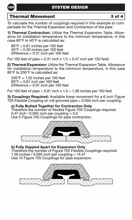
186 SYSTEM DESIGN
To calculate the number of couplings required in this example to com-pensate for the Thermal Expansion and Contraction of the pipe:
1) Thermal Contraction: Utilize the Thermal Expansion Table. Allow-ance for installation temperature to the minimum temperature, in this case 80°F to 40°F is calculated as:
80°F = 0.61 inches per 100 feet 40°F = 0.30 inches per 100 feet Difference = 0.31 inch per 100 feet
For 150 feet of pipe = 0.31 inch x 1.5 = 0.47 inch per 150 feet)
2) Thermal Expansion: Utilize the Thermal Expansion Table. Allowance for installation temperature to the minimum temperature, in this case 80°F to 200°F is calculated as:
200°F = 1.52 inches per 100 feet 80°F = 0.61 inch per 100 feet Difference = 0.91 inch per 100 feet
For 150 feet of pipe = 0.91 inch x 1.5 = 1.36 inches per 150 feet
3) Couplings Required: Available linear movement for a 6 inch Figure 705 Flexible Coupling on roll grooved pipe = 0.094 inch per coupling.
a) Fully Butted Together for Contraction Only Therefore the number of flexible Figure 705 Couplings required: 0.47 inch / 0.094 inch per coupling = 5.0 Use 5 Figure 705 Couplings for pipe contraction.
b) Fully Gapped Apart for Expansion Only Therefore the number of Figure 705 Flexible Couplings required: 1.36 inches / 0.094 inch per coupling = 14.47 Use 15 Figure 705 Couplings for pipe expansion.
3 of 4Thermal Movement
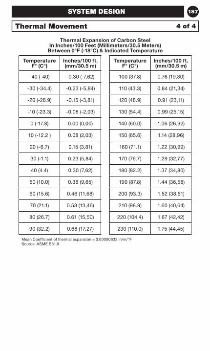
187SYSTEM DESIGN
Thermal Expansion of Carbon Steel In Inches/100 Feet (Millimeters/30.5 Meters)
Between 0°F (-18°C) & Indicated Temperature
Temperature F° (C°)
Inches/100 ft. (mm/30.5 m)
Temperature F° (C°)
Inches/100 ft. (mm/30.5 m)
-40 (-40) -0.30 (-7,62) 100 (37.8) 0.76 (19,30)
-30 (-34.4) -0.23 (-5,84) 110 (43.3) 0.84 (21,34)
-20 (-28.9) -0.15 (-3,81) 120 (48.9) 0.91 (23,11)
-10 (-23.3) -0.08 (-2,03) 130 (54.4) 0.99 (25,15)
0 (-17.8) 0.00 (0,00) 140 (60.0) 1.06 (26,92)
10 (-12.2 ) 0.08 (2,03) 150 (65.6) 1.14 (28,96)
20 (-6.7) 0.15 (3,81) 160 (71.1) 1.22 (30,99)
30 (-1.1) 0.23 (5,84) 170 (76.7) 1.29 (32,77)
40 (4.4) 0.30 (7,62) 180 (82.2) 1.37 (34,80)
50 (10.0) 0.38 (9,65) 190 (87.8) 1.44 (36,58)
60 (15.6) 0.46 (11,68) 200 (93.3) 1.52 (38,61)
70 (21.1) 0.53 (13,46) 210 (98.9) 1.60 (40,64)
80 (26.7) 0.61 (15,50) 220 (104.4) 1.67 (42,42)
90 (32.2) 0.68 (17,27) 230 (110.0) 1.75 (44,45)
Mean Coefficient of thermal expansion = 0.00000633 in/in/°FSource: ASME B31.9
4 of 4Thermal Movement
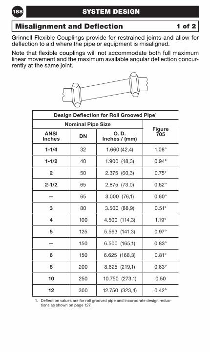
188 SYSTEM DESIGN
Grinnell Flexible Couplings provide for restrained joints and allow for deflection to aid where the pipe or equipment is misaligned.
Note that flexible couplings will not accommodate both full maximum linear movement and the maximum available angular deflection concur-rently at the same joint.
Design Deflection for Roll Grooved Pipe1
Nominal Pipe SizeFigure
705ANSI Inches DN O. D.
Inches / (mm)
1-1/4 32 1.660 (42,4) 1.08°
1-1/2 40 1.900 (48,3) 0.94°
2 50 2.375 (60,3) 0.75°
2-1/2 65 2.875 (73,0) 0.62°
— 65 3.000 (76,1) 0.60°
3 80 3.500 (88,9) 0.51°
4 100 4.500 (114,3) 1.19°
5 125 5.563 (141,3) 0.97°
— 150 6.500 (165,1) 0.83°
6 150 6.625 (168,3) 0.81°
8 200 8.625 (219,1) 0.63°
10 250 10.750 (273,1) 0.50
12 300 12.750 (323,4) 0.42°
1. Deflection values are for roll grooved pipe and incorporate design reduc-tions as shown on page 127.
1 of 2Misalignment and Deflection
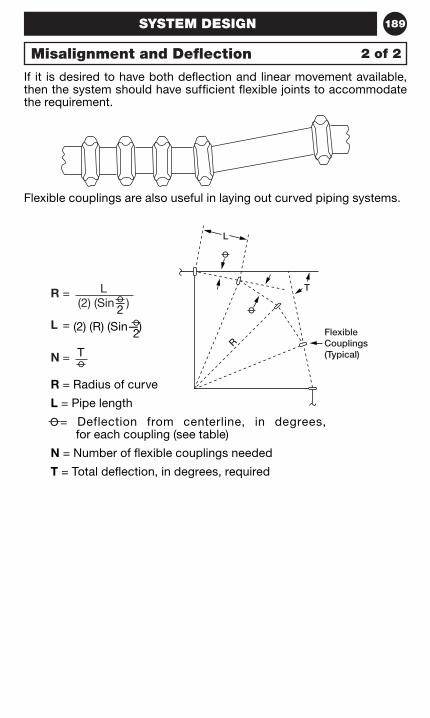
189
L(2) (Sin—)2
(2) (R) (Sin—)2
T
SYSTEM DESIGN
If it is desired to have both deflection and linear movement available, then the system should have sufficient flexible joints to accommodate the requirement.
Flexible couplings are also useful in laying out curved piping systems.
R =
L =
N =
R = Radius of curve
L = Pipe length
= Deflection from centerline, in degrees, for each coupling (see table)
N = Number of flexible couplings needed
T = Total deflection, in degrees, required
2 of 2Misalignment and Deflection
L
T
RFlexibleCouplings(Typical)
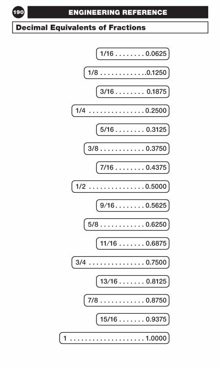
190
Decimal Equivalents of Fractions
1/16 . . . . . . . . 0 .0625
1/8 . . . . . . . . . . . . .0 .1250
3/16 . . . . . . . . 0 .1875
1/4 . . . . . . . . . . . . . . . 0 .2500
5/16 . . . . . . . . 0 .3125
3/8 . . . . . . . . . . . . 0 .3750
7/16 . . . . . . . . 0 .4375
1/2 . . . . . . . . . . . . . . . 0 .5000
9 ⁄ 16 . . . . . . . . 0 .5625
5/8 . . . . . . . . . . . . 0 .6250
11⁄16 . . . . . . . 0 .6875
3/4 . . . . . . . . . . . . . . . 0 .7500
13 ⁄16 . . . . . . . 0 .8125
7/8 . . . . . . . . . . . . 0 .8750
15/16 . . . . . . . 0 .9375
1 . . . . . . . . . . . . . . . . . . . . 1 .0000
ENGINEERING REFERENCE
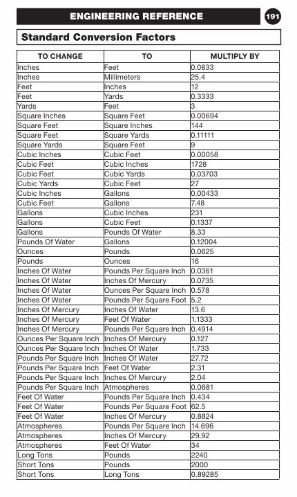
191
TO CHANGE TO MULTIPLY BY
Inches Feet 0.0833Inches Millimeters 25.4Feet Inches 12Feet Yards 0.3333Yards Feet 3Square Inches Square Feet 0.00694Square Feet Square Inches 144Square Feet Square Yards 0.11111Square Yards Square Feet 9Cubic Inches Cubic Feet 0.00058Cubic Feet Cubic Inches 1728Cubic Feet Cubic Yards 0.03703Cubic Yards Cubic Feet 27Cubic Inches Gallons 0.00433Cubic Feet Gallons 7.48Gallons Cubic Inches 231Gallons Cubic Feet 0.1337Gallons Pounds Of Water 8.33Pounds Of Water Gallons 0.12004Ounces Pounds 0.0625Pounds Ounces 16Inches Of Water Pounds Per Square Inch 0.0361Inches Of Water Inches Of Mercury 0.0735Inches Of Water Ounces Per Square Inch 0.578Inches Of Water Pounds Per Square Foot 5.2Inches Of Mercury Inches Of Water 13.6Inches Of Mercury Feet Of Water 1.1333Inches Of Mercury Pounds Per Square Inch 0.4914Ounces Per Square Inch Inches Of Mercury 0.127Ounces Per Square Inch Inches Of Water 1.733Pounds Per Square Inch Inches Of Water 27.72Pounds Per Square Inch Feet Of Water 2.31Pounds Per Square Inch Inches Of Mercury 2.04Pounds Per Square Inch Atmospheres 0.0681Feet Of Water Pounds Per Square Inch 0.434Feet Of Water Pounds Per Square Foot 62.5Feet Of Water Inches Of Mercury 0.8824Atmospheres Pounds Per Square Inch 14.696Atmospheres Inches Of Mercury 29.92Atmospheres Feet Of Water 34Long Tons Pounds 2240Short Tons Pounds 2000Short Tons Long Tons 0.89285
Standard Conversion Factors
ENGINEERING REFERENCE
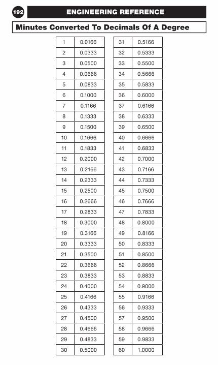
192
1 0.0166 31 0.5166
2 0.0333 32 0.5333
3 0.0500 33 0.5500
4 0.0666 34 0.5666
5 0.0833 35 0.5833
6 0.1000 36 0.6000
7 0.1166 37 0.6166
8 0.1333 38 0.6333
9 0.1500 39 0.6500
10 0.1666 40 0.6666
11 0.1833 41 0.6833
12 0.2000 42 0.7000
13 0.2166 43 0.7166
14 0.2333 44 0.7333
15 0.2500 45 0.7500
16 0.2666 46 0.7666
17 0.2833 47 0.7833
18 0.3000 48 0.8000
19 0.3166 49 0.8166
20 0.3333 50 0.8333
21 0.3500 51 0.8500
22 0.3666 52 0.8666
23 0.3833 53 0.8833
24 0.4000 54 0.9000
25 0.4166 55 0.9166
26 0.4333 56 0.9333
27 0.4500 57 0.9500
28 0.4666 58 0.9666
29 0.4833 59 0.9833
30 0.5000 60 1.0000
Minutes Converted To Decimals Of A Degree
ENGINEERING REFERENCE
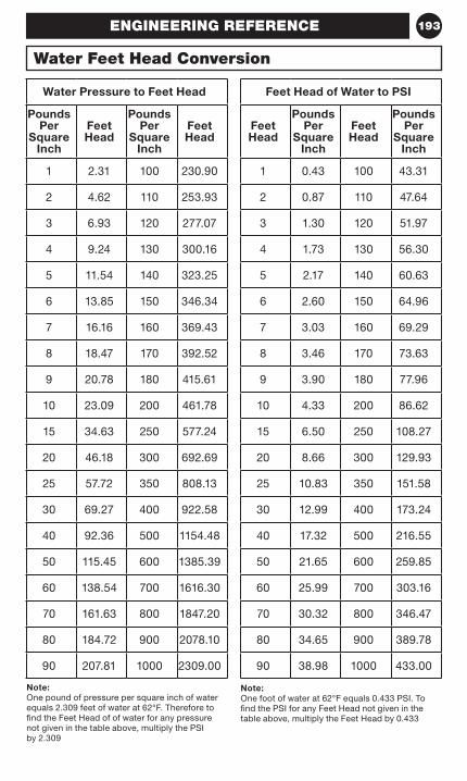
193
Water Pressure to Feet Head
Pounds Per
Square Inch
Feet Head
Pounds Per
Square Inch
Feet Head
1 2.31 100 230.90
2 4.62 110 253.93
3 6.93 120 277.07
4 9.24 130 300.16
5 11.54 140 323.25
6 13.85 150 346.34
7 16.16 160 369.43
8 18.47 170 392.52
9 20.78 180 415.61
10 23.09 200 461.78
15 34.63 250 577.24
20 46.18 300 692.69
25 57.72 350 808.13
30 69.27 400 922.58
40 92.36 500 1154.48
50 115.45 600 1385.39
60 138.54 700 1616.30
70 161.63 800 1847.20
80 184.72 900 2078.10
90 207.81 1000 2309.00
Note:One pound of pressure per square inch of water equals 2.309 feet of water at 62°F. Therefore to find the Feet Head of of water for any pressure not given in the table above, multiply the PSI by 2.309
Feet Head of Water to PSI
Feet Head
Pounds Per
Square Inch
Feet Head
Pounds Per
Square Inch
1 0.43 100 43.31
2 0.87 110 47.64
3 1.30 120 51.97
4 1.73 130 56.30
5 2.17 140 60.63
6 2.60 150 64.96
7 3.03 160 69.29
8 3.46 170 73.63
9 3.90 180 77.96
10 4.33 200 86.62
15 6.50 250 108.27
20 8.66 300 129.93
25 10.83 350 151.58
30 12.99 400 173.24
40 17.32 500 216.55
50 21.65 600 259.85
60 25.99 700 303.16
70 30.32 800 346.47
80 34.65 900 389.78
90 38.98 1000 433.00
Note:One foot of water at 62°F equals 0.433 PSI. To find the PSI for any Feet Head not given in the table above, multiply the Feet Head by 0.433
Water Feet Head Conversion
ENGINEERING REFERENCE
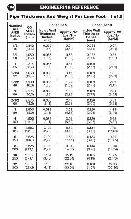
194
Nominal Size ANSI
Inches DN
OD ANSI
Inches (mm)
Schedule 5 Schedule 10
Inside Wall Thickness
Inches (mm)
Approx. Wt. Lbs./ft.- (kg/M)
Inside Wall Thickness
Inches (mm)
Approx. Wt. Lbs./ft.- (kg/M)
1/2 15
0.840 (21,3)
0.065 (1,65)
0.54 (0,80)
0.083 (2,11)
0.67 (0,99)
3/4 20
1.050 (26,7)
0.065 (1,65)
0.68 (1,02)
0.083 (2,11)
0.86 (1,27)
1 25
1.315 (33,7)
0.065 (1,65)
0.87 (1,29)
0.109 (2,77)
1.41 (2,09)
1-1/4 32
1.660 (42,4)
0.065 (1,65)
1.11 (1,65)
0.109 (2,77)
1.81 (2,69)
1-1/2 40
1.900 (48,3)
0.065 (1,65)
1.27 (1,89)
0.109 (2,77)
2.09 (3,11)
2 50
2.375 (60,3)
0.065 (1,65)
1.60 (2,39)
0.109 (2,77)
2.64 (3,93)
2-1/2 65
2.875 (73,0)
0.083 (2,11)
2.47 (3,68)
0.120 (3,05)
3.53 (5,25)
3 80
3.500 (88,9)
0.083 (2,11)
3.03 (4,51)
0.120 (3,05)
4.34 (6,46)
4 100
4.500 (114,3)
0.083 (2,11)
3.91 (5,82)
0.120 (3,05)
5.62 (8,37)
5 125
5.563 (141,3)
0.109 (2,77)
6.35 (9,45)
0.134 (3,40)
7.78 (11,58)
6 150
6.625 (168,3)
0.109 (2,77)
7.58 (11,29)
0.134 (3,40)
9.30 (13,85)
8 200
8.625 (219,1)
0.109 (2,77)
9.91 (14,75)
0.148 (3,76)
13.40 (19,94)
10 250
10.750 (273,1)
0.134 (3,40)
15.19 (22,61)
0.165 (4,19)
18.65 (27,76)
12 300
12.750 (323,9)
0.165 (4,19)
22.18 (33,01)
0.180 (4,57)
24.16 (35,96)
1 of 2Pipe Thickness And Weight Per Line Foot
ENGINEERING REFERENCE
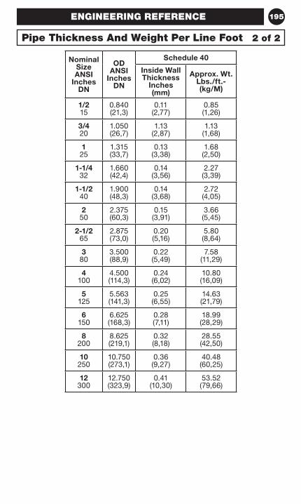
195
Nominal Size ANSI
Inches DN
OD ANSI
Inches DN
Schedule 40
Inside Wall Thickness
Inches (mm)
Approx. Wt. Lbs./ft.- (kg/M)
1/2 15
0.840 (21,3)
0.11 (2,77)
0.85 (1,26)
3/4 20
1.050 (26,7)
1.13 (2,87)
1.13 (1,68)
1 25
1.315 (33,7)
0.13 (3,38)
1.68 (2,50)
1-1/4 32
1.660 (42,4)
0.14 (3,56)
2.27 (3,39)
1-1/2 40
1.900 (48,3)
0.14 (3,68)
2.72 (4,05)
2 50
2.375 (60,3)
0.15 (3,91)
3.66 (5,45)
2-1/2 65
2.875 (73,0)
0.20 (5,16)
5.80 (8,64)
3 80
3.500 (88,9)
0.22 (5,49)
7.58 (11,29)
4 100
4.500 (114,3)
0.24 (6,02)
10.80 (16,09)
5 125
5.563 (141,3)
0.25 (6,55)
14.63 (21,79)
6 150
6.625 (168,3)
0.28 (7,11)
18.99 (28,29)
8 200
8.625 (219,1)
0.32 (8,18)
28.55 (42,50)
10 250
10.750 (273,1)
0.36 (9,27)
40.48 (60,25)
12 300
12.750 (323,9)
0.41 (10,30)
53.52 (79,66)
2 of 2Pipe Thickness And Weight Per Line Foot
ENGINEERING REFERENCE

NOTES196


Technical ServicesTel: +1 (866) 500-4768
Tel: +1 (401) 781-8220
IH-1000FP © 2016 Tyco Fire Products LP. All rights reserved.GRINNELL is a mark and/or registered mark of Tyco International Ltd.
www.grinnell.com
APAC HeadquartersSingapore2 Serangoon North Avenue 5#07-01Singapore 554911
EMEA HeadquartersThe NetherlandsKopersteden 1, P.O. Box 1987500 AD Enschede
China2F, Building No. 1, Lane 955Jinhai Road, PudongShanghai 201206
Hong KongUnits 905-923, 9/F, Trade Square681 Cheung Sha Wan RoadCheung Sha Wan, KowloonHong Kong
India1001, Wing ‘C’, 10th FloorGodrej Coliseum, SionMumbai 400022, India
North America HeadquartersUnited States of America1400 Pennbrook ParkwayLansdale, PA 19446
South America HeadquartersUnited States of America1802 S.W. 2nd StreetPompano Beach, FL 33069
MexicoAv. Presidente Juarez 2007 Lote 6San Jeronimo TepetlacalcoTlalnepantla, Estado de MéxicoMexico 54090
AustraliaLevel 3, 95 Coventry StreetSouthbank, VIC 3006 Australia
United Arab EmiratesPO Box 61355Warehouse TB01, R/A 8Jebel Ali Free Zone, Dubai


![Fire Protection - SmartCockpit A319-320-321 [Fire Protection] Page 1. Airbus A319-320-321 [Fire Protection] ... [Fire Protection] Page 46. Airbus A319-320-321 [Fire Protection] Page](https://img.pdfslide.us/doc/110x75/5aaae6367f8b9a6c188ed0d4/fire-protection-a319-320-321-fire-protection-page-1-airbus-a319-320-321-fire.jpg)