Embed Size (px)
Citation preview
International Journal of Machine Tools & Manufacture 50 (2010) 1077–1087
Contents lists available at ScienceDirect
International Journal of Machine Tools & Manufacture
0890-69
doi:10.1
n Corr
E-m
journal homepage: www.elsevier.com/locate/ijmactool
Grinding characteristics, material removal and damage formationmechanisms in high removal rate grinding of silicon carbide
Sanjay Agarwal a,n, P. Venkateswara Rao b
a Department of Mechanical Engineering, Bundelkhand Institute of Engineering & Technology, Jhansi 284128, Indiab Department of Mechanical Engineering Indian Institute of Technology, New Delhi 110016, India
a r t i c l e i n f o
Article history:
Received 10 October 2009
Received in revised form
21 August 2010
Accepted 27 August 2010Available online 7 September 2010
Keywords:
Advanced ceramics
Surface integrity
Grinding
Silicon carbide
55/$ - see front matter & 2010 Elsevier Ltd. A
016/j.ijmachtools.2010.08.008
esponding author. Tel.: +91 51 0232 0349; fa
ail address: [email protected] (S. Ag
a b s t r a c t
Development of advanced ceramics such as silicon carbide has gained significant importance because of
their desirable properties. However, their engineering applications are still limited owing to the
limitations in developing damage-free and economical machining techniques. It is often desired to
increase the machining rate to improve productivity while maintaining the desired surface integrity.
The success of this approach, however, requires a fundamental understanding of the material removal
and damage formation mechanism in grinding. In this paper, high removal rate grinding of silicon
carbide was investigated with respect to material removal and basic grinding parameters using a
diamond grinding wheel. The results showed that the material removal was primarily due to the
microfracture and grain dislodgement under the grinding conditioned selected. For grain dislodgement
removal mode, the relationship for the removal rate in scratching based on a simple fracture mechanics
analysis has been established. This research provides valuable insights into the surface and subsurface
integrity and material removal mechanism during high removal rate grinding of silicon carbide.
& 2010 Elsevier Ltd. All rights reserved.
1. Introduction
Advanced ceramic materials such as silicon carbide have foundtheir increasing use in bearings, valves, engine components,electronics and bioengineering, etc., because of their superiorproperties such as high temperature strength and hardness, wearand corrosion resistance, thermal stability, chemical inertness andhigh stiffness to weight ratio. However, the machining of ceramicsinto practical forms presents a challenge because of the difficultyand cost involved in the material removal process due to theirhigh hardness and high brittleness. Abrasive machining ofceramics by means of grinding with diamond wheels is theprimary process used in achieving the desired tolerances andsurface integrity. Grinding of silicon carbide is difficult because ofits low fracture toughness, making it very susceptible to cracking.The grinding process is mostly conducted under moderateconditions requiring extensive machining. Efficient grinding ofhigh performance ceramics requires judicious selection ofoperating parameters to maximize removal rate while controllingsurface integrity [1]. Lowering grinding costs by using fasterremoval rates is constrained mainly by damage to the ceramicworkpiece because of the median/lateral cracks that emanateduring grinding. So, it would be essential to understand the
ll rights reserved.
x: +91 51 0232 0312.
arwal).
mechanism of material removal and also to evaluate thesignificance of the process parameters on the required responses.
During the past two decades, extensive research has beenperformed to study the material removal and damage formationmechanism in the grinding of advanced ceramics. However, theindustrial applications of advanced ceramics have been restricted bythe machining difficulties and associated high cost with the use. Thisis mainly due to the poor machinabilty of these ceramics, as a result,great effort were made towards the development of grindingtechnology in an efficient mode [2–7]. High speed grinding hasbeen studied in order to achieve a high material removal rate in thegrinding of ceramics [4]. In the high speed grinding process, anincrease in the wheel speed would reduce the maximum chipthickness, and thus the grinding force [8]. This would cause theductile flow by reducing the tendency for brittle fracture [9]. On theother hand, the increased speed will cause the increase in the depthof cut or the feed rate to obtain the higher material removal rate,without detoriating the ground surface integrity. High removal rategrinding of alumina and alumina–titania was investigated by Yinaet al. [10] with respect to material removal and basic grindingparameters. The results show that the material removal for thesingle-phase polycrystalline alumina and the two-phase alumina–titania composite revealed identical mechanisms of microfractureand grain dislodgement under the grinding conditioned selected.There were no distinct differences in surface roughness andmorphology for both materials ground at either conventional orhigh speed. Also both normal and tangential grinding forces and
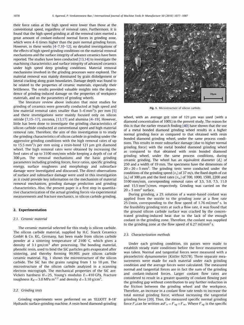
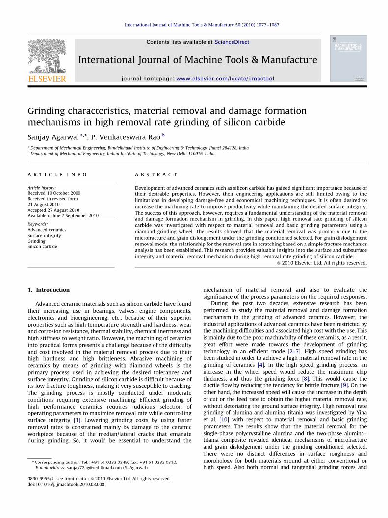
Fig. 1. Microstructure of silicon carbide.
S. Agarwal, P. Venkateswara Rao / International Journal of Machine Tools & Manufacture 50 (2010) 1077–10871078
their force ratios at the high speed were lower than those at theconventional speed, regardless of removal rates. Furthermore, it isfound that the high speed grinding at all the removal rates exerted agreat amount of coolant-induced normal forces in grinding zone,which were 4–6 times higher than the pure normal grinding forces.However, in these works [4–7,10–12], no detailed investigations ofthe effects of high speed grinding conditions on the material removalmechanisms and the surface integrity of advance ceramics have beenreported. The studies have been conducted [13,14] to investigate themachining characteristics and surface integrity of advanced ceramicsunder high speed deep grinding conditions. Material removalmechanisms involved in the grinding processes were explored. Thematerial removal was mainly dominated by grain dislodgement orlateral cracking along grain boundaries. Damage depth was found tobe related to the properties of ceramic materials, especially theirbrittleness. The results provided valuable insights into the depen-dence of grinding-induced damage on the properties of workpiecematerials, and on the parameters of grinding wheels.
The literature review above indicates that most studies forgrinding of ceramics were generally conducted at high speed andlow material removal rates smaller than 5–6 mm3/s per mm [5]and these investigations were mainly focused only on siliconnitride [7,15–17], zirconia, [13,17] and alumina [4–19]. However,little has been done to investigate the grinding characteristics ofsilicon carbide conducted at conventional speed and high materialremoval rate. Therefore, the aim of this investigation is to studythe grinding characteristics of silicon carbide in grinding under theaggressive grinding conditions with the high removal rates of upto 15.5 mm3/s per mm using a resin-bond 121 mm grit diamondwheel. The high removal rates were obtained by increasing thefeed rates of up to 3100 mm/min while keeping a depth of cut of300 mm. The removal mechanisms and the basic grindingparameters including grinding forces, force ratios, specific grindingenergy, surface roughness and morphology and subsurfacedamage were investigated and discussed. The direct observationsof surface and subsurface damage were used in this investigationas it could provide key information on the mechanism of materialremoval mechanism, grinding damage prediction and grindingcharacteristics. Also, the present paper is a first step in quantita-tive characterization of the actual grinding forces via experimentalmeasurements and fracture mechanics, in silicon carbide grinding.
2. Experimentation
2.1. Ceramic material
The ceramic material selected for this study is silicon carbide.The silicon carbide material, supplied by H.C. Starck CeramicsGmbH & Co. KG, Germany, has been made from silicon carbidepowder at a sintering temperature of 2100 1C, which gives adensity of 3.1 gm/cm3 after processing. The bonding material,phenolic resin, used to bind the SiC particles gets evaporated aftersintering, and thereby forming 99.99% pure silicon carbideceramic material. Fig. 1 shows the microstructure of the siliconcarbide. The SiC has the grains ranging from 1 to 10 mm. Themicrostructure of the silicon carbide analyzed in a scanningelectron micrograph. The mechanical properties of the SiC are:Vickers hardness H¼25, Young’s modulus E¼410 GPa, Fracturetoughness KIC¼3.0 MPa m1/2 and density d¼3.10 g/cm3.
2.2. Grinding tests
Grinding experiments were performed on an ‘ELLIOTT 8-18’Hydraulic surface-grinding machine. A resin bond diamond-grinding
wheel, with an average grit size of 121 mm was used (with adiamond concentration of 100%) in the present study. The reason forthis is that the earlier research finding [40] have shown that the useof a metal bonded diamond grinding wheel results in a highernormal grinding force as compared to that obtained with resinbonded diamond grinding wheel, under the same process condi-tions. This results in more subsurface damage (due to higher normalgrinding force) with the metal bonded diamond grinding wheelas compared to that obtained with resin bonded diamondgrinding wheel, under the same process conditions, duringceramic grinding. The wheel has an equivalent diameter (ds) of250 and a width of 19 mm. The specimens have the dimensions of20�20�5 mm3. The grinding tests were conducted under theconditions of the grinding speed (vs) of 37 m/s, the fixed depth of cut(ae) of 300 mm and the feed rates (vw) of 700, 1000, 1500, 2200 and3100 mm/min, corresponding removal rates of 3.5, 5.0, 7.5, 11.0and 15.5 mm3/s/mm, respectively. Grinding was carried on the20�5 mm2 surface.
During grinding, a 2% solution of a water-based coolant wasapplied from the nozzle to the grinding zone at a flow rate25 l/min, corresponding to the flow speed of 1.76 ml/mm2 s. Inthe feasibility grinding tests at such a flow rate, it was found thatthe ground silicon carbide surface was cracked by the concen-trated grinding-induced heat due to the lack of the enoughcoolant in the grinding zone. Therefore, the coolant was suppliedto the grinding zone at the flow speed of 6.27 ml/mm2 s.
2.3. Characterization methods
Under each grinding condition, six passes were made toestablish steady state conditions before the force measurementwas taken. Normal and tangential forces were measured with apiezoelectric dynamometer (Kistler 9257B). Three separate mea-surements were made for each material under each grindingcondition and the average forces were calculated. The measurednormal and tangential forces are in fact the sum of the grindingand coolant-induced forces. Larger coolant flow rates areconsidered to result in a greater quantity of coolant flowing pastthe grinding gap without contribution to any further reduction inthe friction between the grinding wheel and the workpiece.Therefore, an increase in a coolant flow rate tends to increase thetotal normal grinding force, without increasing the tangentialgrinding force [20]. Thus, the measured specific normal grindingforce Funcan be written asFun ¼ FungþFunc . Where Fung is the specific
6
8
10
12
14
16
18
20
22
24
2 6 10 14 18
Mea
sure
d S
peci
ficN
orm
al F
orce
F' n
(N/m
m)
Specific Removal Rate (mm3/s/mm)
Fig. 3. Measured specific normal grinding force Fun versus specific removal rate for
S. Agarwal, P. Venkateswara Rao / International Journal of Machine Tools & Manufacture 50 (2010) 1077–1087 1079
normal grinding force and Func the specific coolant-inductednormal grinding force. The measured specific tangential grindingforce Fut is the specific tangential grinding force. The grindingforce ratio can be written asFung=Fut . The specific grinding energy(Es) can be expressed [21] as Es ¼ Ftvs=aevwb. Where Ft is thetangential grinding force (Newtons), vs the peripheral speed(m/min) of grinding wheel, vw the workpiece feed rate (m/min), ae
the depth of cut (mm) and b the width of cut (mm).After grinding, the ground specimens were cleaned with
acetone in an ultrasonic bath for at least 10 min. The roughnessof the ground surfaces was measured using a Taylor HobsonProfilometer (Talysurf-6 with cutoff value 0.8 mm). The rough-ness was the average value obtained by scanning rectangularsurfaces of the workpiece. After the roughness measurement, theground surfaces were coated with gold and viewed in a scanningelectron microscope to identify the material removal and damageformation mechanisms and surface morphology. A bonded inter-face sectioning technique [22] was used to examine the grinding-induced subsurface damage.
silicon carbide.
6
8
10
12
14
16
18
20
22
24
4 5 6 7 8 9 10 11 12Measured Specific
Tangential Grinding Force F't (N/mm)
Mea
sure
d Sp
ecifi
cN
orm
al G
rindi
ng F
orce
F' n
(N/m
m)
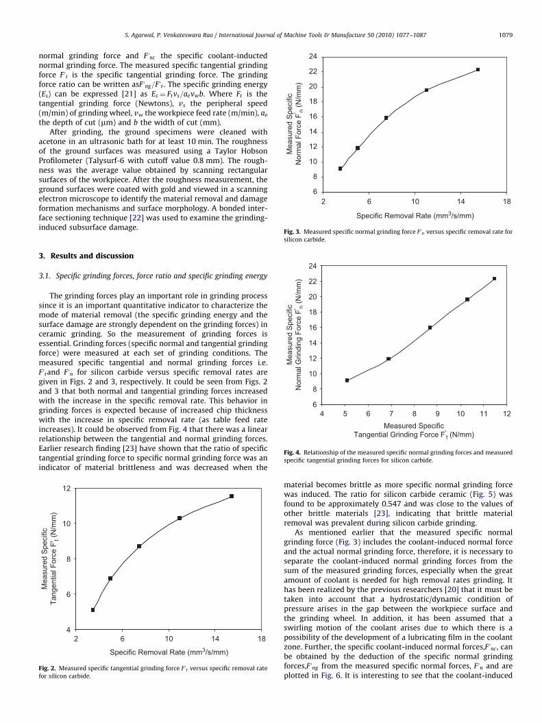
Fig. 4. Relationship of the measured specific normal grinding forces and measured
specific tangential grinding forces for silicon carbide.
3. Results and discussion
3.1. Specific grinding forces, force ratio and specific grinding energy
The grinding forces play an important role in grinding processsince it is an important quantitative indicator to characterize themode of material removal (the specific grinding energy and thesurface damage are strongly dependent on the grinding forces) inceramic grinding. So the measurement of grinding forces isessential. Grinding forces (specific normal and tangential grindingforce) were measured at each set of grinding conditions. Themeasured specific tangential and normal grinding forces i.e.Futand Fun for silicon carbide versus specific removal rates aregiven in Figs. 2 and 3, respectively. It could be seen from Figs. 2and 3 that both normal and tangential grinding forces increasedwith the increase in the specific removal rate. This behavior ingrinding forces is expected because of increased chip thicknesswith the increase in specific removal rate (as table feed rateincreases). It could be observed from Fig. 4 that there was a linearrelationship between the tangential and normal grinding forces.Earlier research finding [23] have shown that the ratio of specifictangential grinding force to specific normal grinding force was anindicator of material brittleness and was decreased when the
4
6
8
10
12
2 6 10 14 18
Mea
sure
d S
peci
ficTa
ngen
tial F
orce
F' t
(N/m
m)
Specific Removal Rate (mm3/s/mm)
Fig. 2. Measured specific tangential grinding force Fut versus specific removal rate
for silicon carbide.
material becomes brittle as more specific normal grinding forcewas induced. The ratio for silicon carbide ceramic (Fig. 5) wasfound to be approximately 0.547 and was close to the values ofother brittle materials [23], indicating that brittle materialremoval was prevalent during silicon carbide grinding.
As mentioned earlier that the measured specific normalgrinding force (Fig. 3) includes the coolant-induced normal forceand the actual normal grinding force, therefore, it is necessary toseparate the coolant-induced normal grinding forces from thesum of the measured grinding forces, especially when the greatamount of coolant is needed for high removal rates grinding. Ithas been realized by the previous researchers [20] that it must betaken into account that a hydrostatic/dynamic condition ofpressure arises in the gap between the workpiece surface andthe grinding wheel. In addition, it has been assumed that aswirling motion of the coolant arises due to which there is apossibility of the development of a lubricating film in the coolantzone. Further, the specific coolant-induced normal forces,Func , canbe obtained by the deduction of the specific normal grindingforces,Fung from the measured specific normal forces, Fun and areplotted in Fig. 6. It is interesting to see that the coolant-induced
0
0.2
0.4
0.6
0.8
0 2.5 5 7.5 10 12.5 15 17.5
Grin
ding
For
ce R
atio
F' t/F
'ng
Specific Removal Rate (mm3/s/mm)
Fig. 5. Grinding force ratio F ut=Fung versus specific removal rate for silicon carbide.
0
0.2
0.4
0.6
0.8
1
1.2
1.4
0 2.5 5 7.5 10 12.5 15 17.5Specific Removal Rate (mm3/s/mm)
Coo
lant
Indu
ced
Spe
cific
Nor
mal
For
ce F
' nc (N
/mm
)
Fig. 6. Specific coolant-induced normal force Func versus specific removal rate for
silicon carbide.
0
10
20
30
40
50
60
2 10 12 14 16 18
Spe
cific
Grin
ding
Ene
rgy
Es
(J/m
m3 )
4 6 8
Specific Removal Rate (mm3/s/mm)
Fig. 8. Specific grinding energy versus specific removal rate for silicon carbide.
0.2
0.4
0.6
0.8
1
1.2
2 4 6 8 10 12 14 16 18
Max
imum
Und
efor
med
Chi
p Th
ickn
ess
t max
(µm
)
Specific Removal Rate (mm3/s/mm)
Fig. 7. Maximum undeformed chip thickness tmax versus specific removal rate.
S. Agarwal, P. Venkateswara Rao / International Journal of Machine Tools & Manufacture 50 (2010) 1077–10871080
substantial normal grinding force in high removal rates grindingoperation. Also the coolant-induced force seems to slightlydecrease with an increase in material removal rates. Thisconfirmed that in high removal rates grinding operation using ahigher flow speed of coolant, substantial hydrodynamic pressurewas built up in the grinding gap between the grinding wheel andthe workpiece, resulting in an extra normal grinding force in thegrinding zone. Generally, it is difficult for the grinding coolant toactually penetrate into the grinding zone during high removalrate grinding. However, in some cases it may be possible that asmall amount of grinding coolant penetrate the grinding zone viamechanisms such as vibration, capillary action or diffusion [24]. Ithas been established by Hryniewicz et al. [25] that only a portionof the coolant, flowing through the grinding zone, is effective andmost of the fluid travels on the wheel surface. According toNavier–Stoke equations, when a water-based coolant is applied inthe grinding zone, the shear forces or frictional forces in thegrinding zone could be neglected due to its low viscosity. Thissuggests that increasing the coolant flow rate does not necessarilycause any further reduction in the friction at the workpiece/grinding wheel interface. Therefore, the application of largeamount of low viscosity water-based coolant will not induceany additional tangential grinding force in the grinding zone; it
increases only to the total normal grinding force. In the presentinvestigation, the measured tangential grinding force was con-sidered as the actual grinding force.
In the grinding of advanced ceramics, the material removalmechanism depends upon the chip formation characterized byplastic flow or brittle fracture as the cutting depth increases. If thecutting depth is large enough to cause cracks, a chip removal willbe due to the fracture of material. When fracture occurs, thespecific energy requirement is lower than that in normal chipformation, but the surface damage occur leading to strengthreduction. Quantitatively, the parameter tmax (maximum unde-formed chip thickness) characterizes the depth of penetration ofthe abrasive grain into the workpiece when it is engaged incutting. The value of tmax thus represents the effect of grindingconditions on the grinding force well and depends on bothmachine and wheel parameters. The tmax can be expressed as [26]
tmax ¼E1
E2
� �0:548 4
Cr
vw
vs
� �ae
ds
� �1=2" #1=2
ð1Þ
where r is the chip width-to-thickness ratio, C the number ofactive grits per unit area of the wheel periphery (grit surfacedensity), E1 the modulus of elasticity of the wheel, E2 the modulus
S. Agarwal, P. Venkateswara Rao / International Journal of Machine Tools & Manufacture 50 (2010) 1077–1087 1081
of elasticity of the workpiece, vw the workpiece feed rate, vs thewheel velocity, ae the depth of cut and ds the equivalent wheeldiameter. The value of r as in Eq. (1) is difficult to determine and isreported in the range 10–20 [27]; r was assumed to be equal to 10in this work. The equivalent wheel diameter in surface grinding isthe wheel diameter itself. The modulus of elasticity of thediamond-grinding wheel (E1) is assumed to be the modulus ofelasticity of the core material of the wheel itself. This is becausethe amount of the abrasive layer on the core is only 4 mm thick(6% by volume) and the core material is of 242 mm diameter(94% by volume) in a grinding wheel of 250 mm diameter.Alminium is the core material used in the diamond grindingwheels and thus the modulus of elasticity of the wheel is taken asthe modulus of elasticity of alminium, which is 70 GPa. HenceE1 is taken as 70 GPa in the present study. The value of modulus ofelasticity of the workpiece (E2) is taken as 410 GPa, which isprovided by the manufacturer of the silicon carbide workpiece.The value of C, in Eq. (1), can be obtained by a simple geometric
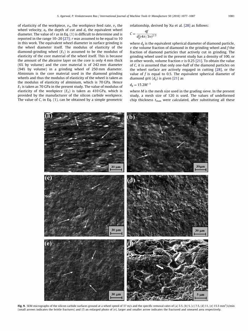
Fig. 9. SEM micrographs of the silicon carbide surfaces ground at a wheel speed of 37 m
(small arrows indicates the brittle fractures) and (f) an enlarged photo of (e), larger an
relationship, derived by Xu et al. [28] as follows:
C ¼4f
d2g ð4p=3vÞ2=3
where dg is the equivalent spherical diameter of diamond particle,v the volume fraction of diamond in the grinding wheel and f thefraction of diamond particles that actively cut in grinding. Thegrinding wheel used in the present study has a density of 100, orin other words, volume fraction v is 0.25 [21]. To obtain the valueof C, it is assumed that only one-half of the diamond particles onthe wheel surface are actively engaged in cutting [28], or thevalue of f is equal to 0.5. The equivalent spherical diameter ofdiamond grit (dg) is given [21] as
dg ¼ 15:2M�1
where M is the mesh size used in the grading sieve. In the presentstudy, a mesh size of 120 is used. The values of undeformedchip thickness tmax were calculated, after substituting all these
/s and the specific removal rates of (a) 3.5, (b) 5, (c) 7.5, (d) 11, (e) 15.5 mm3/s/min
d smaller arrow indicates the fractured and smeared area respectively.

0.1
0.2
0.3
0.4
0.5
0.6
0.7
0 5 10 15 20
Sur
face
Rou
ghne
ss (µ
m)
Average value ofsurface roughness
Specific Removal Rate (mm3/s/mm)
Fig. 10. Surface roughness versus specific removal rate for silicon carbide.
S. Agarwal, P. Venkateswara Rao / International Journal of Machine Tools & Manufacture 50 (2010) 1077–10871082
parameters in Eq. (1) and represented in graphical form as shownin Fig. 7. Eq. (1) shows that not only the machining parameters(ae, vw, vs) modify the tmax but also the wheel parameters, such asC and r. The C and r, in turn, depends on the wheel topography,which includes the distance between the consecutive grains. Thisdistance is related to the grit size, the diamond type and theconcentration. In general, smaller tmax is desirable to give longerwheel life, lower forces and better surface integrity [6,8,21]. Forachieving the higher material removal rate, a higher value of theproduct (ae.vw) is desirable. This in turn would make theundeformed chip thickness tmax larger. In other words, highmaterial removal rate often contradicts with smaller tmax, or lowdamage. The grinding with high depth of cut and low table feedcan lead to both high material removal rate and low undeformedchip thickness.
In the case of surface grinding process, the specific grindingenergy, Es, which is an important parameter in the grinding ofbrittle materials since its value results from the mechanismassociated with interaction between the abrasive grit and theworkpiece. The specific grinding energy, Es, for silicon carbideversus specific removal rate is given in Fig. 8. It could be seen fromthis figure that specific grinding energy decreased from 53.9 to27.45 J/mm3 with an increase in specific removal rate from 3.5 to15.5 mm3/s per mm. The decrease in specific grinding energy withincreasing removal rate for silicon carbide is similar to what isfound with other ceramics such as silicon nitride in conventionalgrinding [29]. As what was found in the SEM micrographs in Fig. 9that in the high removal rate grinding at conventional speed,material removal for silicon carbide was fully conducted in afracture mode. This estimation was further confirmed by havingan enlarge view of one of the ground workpiece surface (Fig. 9(f)),where arrow indicated the fractured area and pits resulting fromgrain dislodgement and was consistent with the observations onmachining of other materials including alumina [30] and glass-ceramics [31]. However it is difficult to quantitatively identify theeffect of the grinding conditions on the surface characteristicsthrough SEM micrographs.
3.2. Surface roughness and surface morphology
In addition to the tangential grinding force and specificgrinding energy, surface roughness is also an indicator tocharacterize the material removal mode associated with thegrinding process. The quality of surface generated during ceramicgrinding process depends upon grinding conditions. The surfaceroughness data obtained from the ground surfaces with respect tothe specific removal rate have been shown in Fig. 10. It could beseen from Fig. 10 that average surface roughness (average ofseven measurements) is almost same when increasing thematerial removal rate. In fact, the ground surface morphologyshown in Fig. 9 indicates that an increase in material removal ratedid not affect surface finish and surface morphology. Thisindication gives an important insight into ceramic machiningthat silicon carbide can be efficiently ground without causing aloss of surface integrity.
3.3. Subsurface grinding damage
The subsurface damage of the ground specimens, which wereprepared using the bonded interface sectioning technique, wasexamined using an SEM. Two types of subsurface damage,chipping and cracking, induced by grinding were clearly observed.The damage layer right underneath the machined surface exhibitsto be generated via chipping, and the chipping layer exhibits to beinduced mainly by grain dislodgement as shown in Fig. 11. During
grinding, the contact of an individual diamond particle with theceramic workpiece produced a damage zone containing distrib-uted grain-boundary microcracks. This damaged layer contributesto the dislodgement of individual grains resulting from the grain-boundary microfractures. This fact led to the conclusion that thechipping layers were induced by grain dislodgements. Thechipping effect for lower specific removal rate was more over-whelming and probably covered the damage layer. This could bedue to the fact that as table feed rate in grinding was decreased,the local contact force and the number of contacting diamondparticles would increase, leading to a possible removal of asegment of material that contains a number of individual grains,besides the dislodgement of individual grains. Apart from this,microcracks were also observed (as indicated by arrows in Fig. 14)in the subsurface layer of the ground silicon carbide, usuallyunder the chipping layer. Most of the microcracks were observedalong the grain boundaries. These results are in agreement withthe surface characteristics shown in Fig. 9.
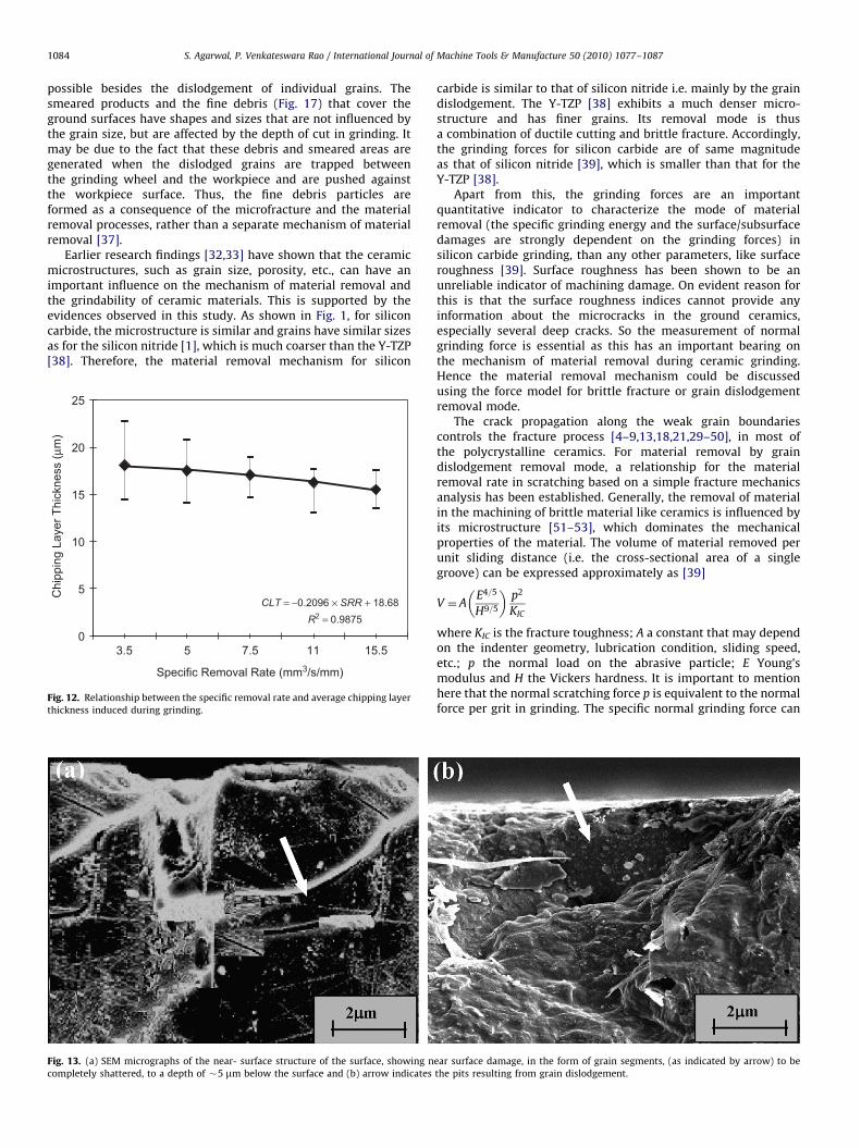
The chipping layer thickness was measured during the SEMexamination. Since the chipping layer was uneven, measurementsat seven locations uniformly distributed along the grinding widthfor each specimen were taken. The chipping layer thickness,obtained from the ground surfaces, with respect to the specificremoval rates, has been shown in Fig. 12. Each data point (Fig. 12)was the average of seven measurements and the error barsindicated the maximum and minimum values of thicknessmeasured. Since there was a significant dispersion in themeasured values of chipping layer thickness, it would be essentialto perform the statistical analysis to establish a relationshipbetween the chipping layer thickness (CLT) and the specificremoval rate (SRR). In fact, Fig. 12 shows there to be a linearrelationship between chipping layer thickness (CLT) and thespecific removal rate (SRR). Statistical analysis determines thatthey are related by the expression CLT¼�0.2096� SRR+18.68.Thus, the more the specific removal rate, thinner the chippinglayer thickness. This confirmed our surface roughness results asshown in Fig. 10.
In addition to the chipping layer, microcracks induced bygrinding were observed in the subsurface layer of the groundsilicon carbide, underneath the chipping layer. Most microcrackswere observed along the grain boundaries as shown in Figs. 13and 14. Evidently, the material removal was due to thedislodgement of individual grains, resulting from microcracksalong the grain boundaries. This fact was supported by the surface
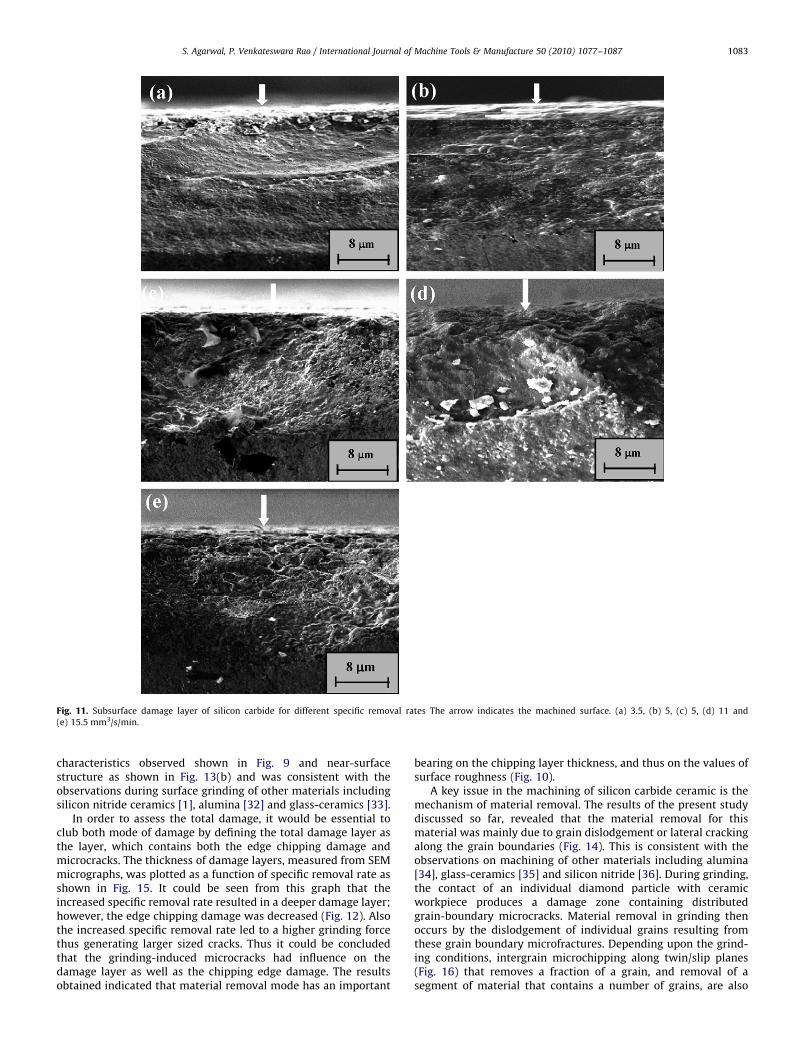
Fig. 11. Subsurface damage layer of silicon carbide for different specific removal rates The arrow indicates the machined surface. (a) 3.5, (b) 5, (c) 5, (d) 11 and
(e) 15.5 mm3/s/min.
S. Agarwal, P. Venkateswara Rao / International Journal of Machine Tools & Manufacture 50 (2010) 1077–1087 1083
characteristics observed shown in Fig. 9 and near-surfacestructure as shown in Fig. 13(b) and was consistent with theobservations during surface grinding of other materials includingsilicon nitride ceramics [1], alumina [32] and glass-ceramics [33].
In order to assess the total damage, it would be essential toclub both mode of damage by defining the total damage layer asthe layer, which contains both the edge chipping damage andmicrocracks. The thickness of damage layers, measured from SEMmicrographs, was plotted as a function of specific removal rate asshown in Fig. 15. It could be seen from this graph that theincreased specific removal rate resulted in a deeper damage layer;however, the edge chipping damage was decreased (Fig. 12). Alsothe increased specific removal rate led to a higher grinding forcethus generating larger sized cracks. Thus it could be concludedthat the grinding-induced microcracks had influence on thedamage layer as well as the chipping edge damage. The resultsobtained indicated that material removal mode has an important
bearing on the chipping layer thickness, and thus on the values ofsurface roughness (Fig. 10).
A key issue in the machining of silicon carbide ceramic is themechanism of material removal. The results of the present studydiscussed so far, revealed that the material removal for thismaterial was mainly due to grain dislodgement or lateral crackingalong the grain boundaries (Fig. 14). This is consistent with theobservations on machining of other materials including alumina[34], glass-ceramics [35] and silicon nitride [36]. During grinding,the contact of an individual diamond particle with ceramicworkpiece produces a damage zone containing distributedgrain-boundary microcracks. Material removal in grinding thenoccurs by the dislodgement of individual grains resulting fromthese grain boundary microfractures. Depending upon the grind-ing conditions, intergrain microchipping along twin/slip planes(Fig. 16) that removes a fraction of a grain, and removal of asegment of material that contains a number of grains, are also
S. Agarwal, P. Venkateswara Rao / International Journal of Machine Tools & Manufacture 50 (2010) 1077–10871084
possible besides the dislodgement of individual grains. Thesmeared products and the fine debris (Fig. 17) that cover theground surfaces have shapes and sizes that are not influenced bythe grain size, but are affected by the depth of cut in grinding. Itmay be due to the fact that these debris and smeared areas aregenerated when the dislodged grains are trapped betweenthe grinding wheel and the workpiece and are pushed againstthe workpiece surface. Thus, the fine debris particles areformed as a consequence of the microfracture and the materialremoval processes, rather than a separate mechanism of materialremoval [37].
Earlier research findings [32,33] have shown that the ceramicmicrostructures, such as grain size, porosity, etc., can have animportant influence on the mechanism of material removal andthe grindability of ceramic materials. This is supported by theevidences observed in this study. As shown in Fig. 1, for siliconcarbide, the microstructure is similar and grains have similar sizesas for the silicon nitride [1], which is much coarser than the Y-TZP[38]. Therefore, the material removal mechanism for silicon
Fig. 13. (a) SEM micrographs of the near- surface structure of the surface, showing n
completely shattered, to a depth of �5 mm below the surface and (b) arrow indicates
0
5
10
15
20
25
3.5 5 7.5 11 15.5
Chi
ppin
g La
yer T
hick
ness
(µm
)
R2 = 0.9875CLT = −0.2096 × SRR + 18.68
Specific Removal Rate (mm3/s/mm)
Fig. 12. Relationship between the specific removal rate and average chipping layer
thickness induced during grinding.
carbide is similar to that of silicon nitride i.e. mainly by the graindislodgement. The Y-TZP [38] exhibits a much denser micro-structure and has finer grains. Its removal mode is thusa combination of ductile cutting and brittle fracture. Accordingly,the grinding forces for silicon carbide are of same magnitudeas that of silicon nitride [39], which is smaller than that for theY-TZP [38].
Apart from this, the grinding forces are an importantquantitative indicator to characterize the mode of materialremoval (the specific grinding energy and the surface/subsurfacedamages are strongly dependent on the grinding forces) insilicon carbide grinding, than any other parameters, like surfaceroughness [39]. Surface roughness has been shown to be anunreliable indicator of machining damage. On evident reason forthis is that the surface roughness indices cannot provide anyinformation about the microcracks in the ground ceramics,especially several deep cracks. So the measurement of normalgrinding force is essential as this has an important bearing onthe mechanism of material removal during ceramic grinding.Hence the material removal mechanism could be discussedusing the force model for brittle fracture or grain dislodgementremoval mode.
The crack propagation along the weak grain boundariescontrols the fracture process [4–9,13,18,21,29–50], in most ofthe polycrystalline ceramics. For material removal by graindislodgement removal mode, a relationship for the materialremoval rate in scratching based on a simple fracture mechanicsanalysis has been established. Generally, the removal of materialin the machining of brittle material like ceramics is influenced byits microstructure [51–53], which dominates the mechanicalproperties of the material. The volume of material removed perunit sliding distance (i.e. the cross-sectional area of a singlegroove) can be expressed approximately as [39]
V ¼ AE4=5
H9=5
� �p2
KIC
where KIC is the fracture toughness; A a constant that may dependon the indenter geometry, lubrication condition, sliding speed,etc.; p the normal load on the abrasive particle; E Young’smodulus and H the Vickers hardness. It is important to mentionhere that the normal scratching force p is equivalent to the normalforce per grit in grinding. The specific normal grinding force can
ear surface damage, in the form of grain segments, (as indicated by arrow) to be
the pits resulting from grain dislodgement.
Fig. 14. SEM micrographs of the specimen ground at higher specific removal rate,
with specimen tilted so that both surface and section are visible. The arrows
indicate the grain boundary microcracks and pits resulting from grain dislodge-
ment.
0
5
10
15
20
25
30
35
40
3.5 5 7.5 11 15.5
Tota
l Dam
age
Thic
knes
s (m
icro
ns)
Specific Removal Rate (mm3/s/mm)
Fig. 15. Effect of specific removal rate on the total damage layer thickness. The
upper and lower bars show the maximum and minimum thickness measured.
Fig. 16. SEM micrograph shows the grain boundary microcracks and intergrain
twin/slip bands indicated by large and small arrows.
Fig. 17. SEM micrograph shows the area of the surface ground covered with
debris.
S. Agarwal, P. Venkateswara Rao / International Journal of Machine Tools & Manufacture 50 (2010) 1077–1087 1085
be expressed as [39]
Fung ¼ bK1=2
IC H9=10
E2=5
!vw
vs
� �3=4
a11=12e d1=12
s ð2Þ
where b is a constant that includes information related to thewheel topography. Eq. (2) could be simplified to the followingform by ignoring the parameters with small exponents and byrounding off some of the exponents [39]:
Fung ¼ bK1=2
IC H
E2=5
!vw
vs
� �3=4
ae ð3Þ
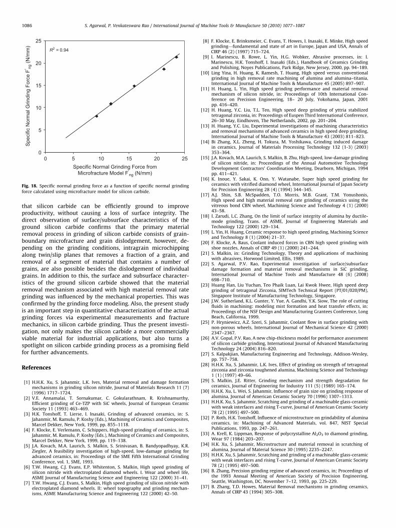
This equation indicates that the specific normal grinding forceis dependent on mechanical properties of the workpiece materialand the grinding parameters., the constant b can be approxi-mately equal to 0.85 [39], for grinding conducted in a micro-fracture mode. Using Eq. (3) above, the normal grinding force canbe calculated using the mechanical properties of silicon carbideand the grinding conditions considered. The specific normalgrinding force is plotted with respect to specific normal grinding
force calculated with the model (Fig. 18). It can be observed fromthese graphs that there exists a good linear correlation (R2
¼0.94)between the measured values and values obtained from themicrofracture (or grain dislodgement) model. This indicates thatthe brittle fracture followed by grain dislodgement is thedominant material removal mode in the grinding of siliconcarbide, which is in a good agreement with the machined surfacecharacteristics (SEM micrographs).
4. Conclusion
This experimental study investigates the grinding character-istics and surface and subsurface integrity of ground siliconcarbide to explore the material removal and damage formationmechanisms involved during high removal rate grinding. Theexperimental investigations revealed that an increase in materialremoval rate did not affect surface finish and surface morphology.This indication gives an important insight into ceramic machining
0
5
10
15
20
25
0 5 10 15 20 25Specific Normal Grinding Force from
Microfracture Model F'ng (N/mm)
Spe
cific
Nor
mal
Grin
ding
For
ce F
' ng (N
/mm
)
R2 = 0.94
Fig. 18. Specific normal grinding force as a function of specific normal grinding
force calculated using microfracture model for silicon carbide.
S. Agarwal, P. Venkateswara Rao / International Journal of Machine Tools & Manufacture 50 (2010) 1077–10871086
that silicon carbide can be efficiently ground to improveproductivity, without causing a loss of surface integrity. Thedirect observation of surface/subsurface characteristics of theground silicon carbide confirms that the primary materialremoval process in grinding of silicon carbide consists of grain-boundary microfracture and grain dislodgement, however, de-pending on the grinding conditions, intragrain microchippingalong twin/slip planes that removes a fraction of a grain, andremoval of a segment of material that contains a number ofgrains, are also possible besides the dislodgement of individualgrains. In addition to this, the surface and subsurface character-istics of the ground silicon carbide showed that the materialremoval mechanism associated with high material removal rategrinding was influenced by the mechanical properties. This wasconfirmed by the grinding force modeling. Also, the present studyis an important step in quantitative characterization of the actualgrinding forces via experimental measurements and fracturemechanics, in silicon carbide grinding. Thus the present investi-gation, not only makes the silicon carbide a more commerciallyviable material for industrial applications, but also turns aspotlight on silicon carbide grinding process as a promising fieldfor further advancements.
References
[1] H.H.K. Xu, S. Jahanmir, L.K. Ives, Material removal and damage formationmechanisms in grinding silicon nitride, Journal of Materials Research 11 (7)(1996) 1717–1724.
[2] V.E. Annamalai, T. Sornakumar, C. Gokularathnam, R. Krishnamurthy,Efficient grinding of Ce-TZP with SiC wheels, Journal of European CeramicSociety 11 (1993) 463–469.
[3] H.K. Tonshoff, T. Lierse, I. Inasaki, Grinding of advanced ceramics, in: S.Jahanmir, M. Ramulu, P. Koshy (Eds.), Machining of Ceramics and Composites,Marcel Dekker, New York, 1999, pp. 855–1118.
[4] F. Klocke, E. Verlemann, C. Schippers, High-speed grinding of ceramics, in: S.Jahanmir, M. Ramulu, P. Koshy (Eds.), Machining of Ceramics and Composites,Marcel Dekker, New York, 1999, pp. 119–138.
[5] J.A. Kovach, M.A. Laurich, S. Malkin, S. Srinivasan, B. Bandyopadhyay, K.R.Ziegler, A feasibility investigation of high-speed, low-damage grinding foradvanced ceramics, in: Proceedings of the SME Fifth International GrindingConference, vol. 1, SME, 1993.
[6] T.W. Hwang, C.J. Evans, E.P. Whitenton, S. Malkin, High speed grinding ofsilicon nitride with electroplated diamond wheels. I. Wear and wheel life,ASME Journal of Manufacturing Science and Engineering 122 (2000) 31–41.
[7] T.W. Hwang, C.J. Evans, S. Malkin, High speed grinding of silicon nitride withelectroplated diamond wheels. II: wheel topography and grinding mechan-isms, ASME Manufacturing Science and Engineering 122 (2000) 42–50.
[8] F. Klocke, E. Brinksmeier, C. Evans, T. Howes, I. Inasaki, E. Minke, High speedgrinding—fundamental and state of art in Europe, Japan and USA, Annals ofCIRP 46 (2) (1997) 715–724.
[9] I. Marinescu, B. Rowe, L. Yin, H.G. Wobker, Abrasive processes, in: I.Marinescu, H.K. Tonshoff, I. Inasaki (Eds.), Handbook of Ceramics Grindingand Polishing, Noyes Publications, Park Ridge, New Jersey, 2000, pp. 94–189.
[10] Ling Yina, H. Huang, K. Ramesh, T. Huang, High speed versus conventionalgrinding in high removal rate machining of alumina and alumina–titania,International Journal of Machine Tools & Manufacture 45 (2005) 897–907.
[11] H. Huang, L. Yin, High speed grinding performance and material removalmechanism of silicon nitride, in: Proceedings of 10th International Con-ference on Precision Engineering, 18– 20 July, Yokohama, Japan, 2001pp. 416–420.
[12] H. Huang, Y.C. Liu, T.L. Teo, High speed deep grinding of yttria stabilizedtetragonal zirconia, in: Proceedings of Euspen Third International Conference,26–30 May, Eindhoven, The Netherlands, 2002, pp. 201–204.
[13] H. Huang, Y.C. Liu, Experimental investigations of machining characteristicsand removal mechanisms of advanced ceramics in high speed deep grinding,International Journal of Machine Tools & Manufacture 43 (2003) 811–823.
[14] Bi Zhang, X.L. Zheng, H. Tokura, M. Yoshikawa, Grinding induced damagein ceramics, Journal of Materials Processing Technology 132 (1-3) (2003)353–364.
[15] J.A. Kovach, M.A. Laurich, S. Malkin, B. Zhu, High-speed, low-damage grindingof silicon nitride, in: Proceedings of the Annual Automotive TechnologyDevelopment Contractors’ Coordination Meeting, Dearborn, Michigan, 1994pp. 411–421.
[16] K. Inoue, Y. Sakai, K. Ono, Y. Watanabe, Super high speed grinding forceramics with vitrified diamond wheel, International Journal of Japan Societyfor Precision Engineering 28 (4) (1994) 344–345.
[17] A.J. Shin, S.B. McSpadden, T.O. Morris, M.B. Grant, T.M. Yonushonis,High speed and high material removal rate grinding of ceramics using thevitreous bond CBN wheel, Machining Science and Technology 4 (1) (2000)43–58.
[18] I. Zarudi, L.C. Zhang, On the limit of surface integrity of alumina by ductile-mode grinding, Trans. of ASME, Journal of Engineering Materials andTechnology 122 (2000) 129–134.
[19] L. Yin, H. Huang, Ceramic response to high speed grinding, Machining Scienceand Technology 8 (1) (2004) 21–37.
[20] F. Klocke, A. Baus, Coolant induced forces in CBN high speed grinding withshoe nozzles, Annals of CIRP 49 (1) (2000) 241–244.
[21] S. Malkin, in: Grinding Technology, Theory and applications of machiningwith abrasives, Horwood Limited, Ellis, 1989.
[22] S. Agarwal, P.V. Rao, Experimental investigation of surface/subsurfacedamage formation and material removal mechanisms in SiC grinding,International Journal of Machine Tools and Manufacture 48 (6) (2008)698–710.
[23] Huang Han, Liu Yuchan, Teo Phaik Luan, Lai Kwok Hwee, High speed deepgrinding of tetragonal Zirconia, SIMTech Technical Report (PT/01/020/PM),Singapore Institute of Manufacturing Technology, Singapore.
[24] J.W. Sutherland, K.L. Gunter, Y. Yue, A. Gandhi, Y.K. Siow, The role of cuttingfluids in machining: modeling mist formation and heat transfer effects, in:Proceedings of the NSF Design and Manufacturing Grantees Conference, LongBeach, California, 1999.
[25] P. Hryniewicz, A.Z. Szeri, S. Jahanmir, Coolant flow in surface grinding withnon-porous wheels, International Journal of Mechanical Science 42 (2000)2347–2367.
[26] A.V. Gopal, P.V. Rao, A new chip-thickness model for performance assessmentof silicon carbide grinding, International Journal of Advanced ManufacturingTechnology 24 (2004) 816–820.
[27] S. Kalpakjian, Manufacturing Engineering and Technology, Addison-Wesley,pp. 757–758.
[28] H.H.K. Xu, S. Jahanmir, L.K. Ives, Effect of grinding on strength of tetragonalzirconia and zirconia toughened alumina, Machining Science and Technology1 (1) (1997) 49–66.
[29] S. Malkin, J.E. Ritter, Grinding mechanism and strength degradation forceramics, Journal of Engineering for Industry 111 (5) (1989) 165–174.
[30] H.H.K. Xu, L. Wei, S. Jahanmir, Influence of grain size on grinding response ofalumina, Journal of American Ceramic Society 70 (1996) 1307–1313.
[31] H.H.K. Xu, S. Jahanmir, Scratching and grinding of a machinable glass-ceramicwith weak interfaces and rising T-curve, Journal of American Ceramic Society78 (2) (1995) 497–500.
[32] P. Roth, H.K. Tonshoff, Influence of microstructure on grindability of aluminaceramics, in: Machining of Advanced Materials, vol. 847, NIST SpecialPublications, 1993, pp. 247–261.
[33] A. Krell, K. Lippman, Response of polycrystalline Al2O3 to diamond grinding,Wear 97 (1984) 203–207.
[34] H.K. Xu, S. Jahanmir, Microstructure and material removal in scratching ofalumina, Journal of Material Science 30 (1995) 2235–2247.
[35] H.H.K. Xu, S. Jahanmir, Scratching and grinding of a machinable glass-ceramicwith weak interfaces and rising T-curve, Journal of American Ceramic Society78 (2) (1995) 497–500.
[36] B. Zhang, Precision grinding regime of advanced ceramics, in; Proceedings ofthe 1993 Annual Meeting of American Society of Precision Engineering,Seattle, Washington, DC, November 7–12, 1993, pp. 225-229.
[37] B. Zhang, T.D. Howes, Material Removal mechanisms in grinding ceramics,Annals of CIRP 43 (1994) 305–308.
S. Agarwal, P. Venkateswara Rao / International Journal of Machine Tools & Manufacture 50 (2010) 1077–1087 1087
[38] H. Huang, Y.C. Liu, Experimental investigations of machining characteristicsand removal mechanisms of advanced ceramics in high speed deep grinding,International Journal of Machine Tools & Manufacture 43 (2003) 811–823.
[39] S. Jahanmir, H.H.K. Xu, L.K. Ives, Mechanisms of material removal in abrasivemachining of ceramics, in: S. Jahanmir, M. Ramulu, P. Koshy (Eds.), Machiningof Ceramics and Composites, Marcel Dekker, New York, 1999, pp. 11–84.
[40] I. Inasaki, Grinding of hard and brittle materials, Annals of CIRP 36 (2) (1987)463–471.
[41] H. Huang, L. Yin, L. Zhou, High speed grinding of silicon nitride with resinbond diamond wheels, Journal of Materials Processing Technology 141(2003) 329–336.
[43] T.W. Hwang, C.J. Evans, S. Malkin, An investigation of high speed grindingwith electroplated diamond wheels, Annals of CIRP 49 (1) (2000) 245–248.
[44] N.P. Padture, B.R. Lawn, Fatigue in ceramics with interconnecting weakinterfaces: a study using cyclic Hertzian contacts, Acta MetallurgicalMaterials 43 (4) (1995) 1609–1617.
[45] F. Guiberteau, N.P. Padture, B.R. Lawn, Effect of grain size on Hertzian damagein alumina, Journal of American Ceramic Society 77 (7) (1994) 1825–1831.
[46] H.H.K. Xu, S. Jahanmir, Y. Wang, Effect of grain size on scratch interactionsand materials removal in alumina, Journal of American Ceramic Society78 (4) (1995) 881–891.
[47] H.H.K. Xu, S. Jahanmir, Transitions in the mechanism of material removal inabrasive wear of alumina, Wear 192 (1996) 228–232.
[48] L. Yin, S. Jahanmir, L.K. Ives, Abrasive machining of porcelain and zirconiawith a dental handpiece, Wear 255 (2003) 975–989.
[49] X. Dong, L. Yin, S. Jahanmir, L.K. Ives, E.D. Rekow, Abrasive machining ofglass–ceramics with a dental handpiece, Machining Science and Technology4 (2) (2000) 209–233.
[50] L. Yin, L.K. Ives, S. Jahanmir, E.D. Rekow, E. Romberg, Abrasive machining ofglass-infiltrated alumina with diamond burs, Machining Science andTechnology 5 (1) (2001) 43–61.
[51] L. Yin, A.C. Spowage, K. Ramesh, H. Huang, J.P. Pickering, E.Y.J. Vancoille,Influence of microstructure on ultraprecision grinding of cemented carbides,International Journal of Machine Tools and Manufacture 44 (5) (2004)533–543.
[52] L. Yin, E.Y.J. Vancoille, K. Ramesh, H. Huang, Surface characterizationof 6H-SiC (0 0 0 1) substrates in indentation and abrasive machining,International Journal of Machine Tools and Manufacture 44 (2004)607–615.
[53] L. Yin, E.Y.J. Vancoille, L.C. Lee, H. Huang, K. Ramesh, X.D. Liu, High-qualitygrinding of polycrystalline silicon carbide spherical surfaces, Wear 256 (1–2)(2004) 197–207.


![Centers for Turning and Grinding - Powerhold, Incpowerholdinc.com/uploads/products/21_CarbideDeadCenters[1].pdf · Carbide dead centres Roundness achieves roundness When grinding,](https://img.pdfslide.us/doc/110x75/5a7e878f7f8b9a66798e90ae/centers-for-turning-and-grinding-powerhold-1pdfcarbide-dead-centres-roundness.jpg)