Embed Size (px)
Citation preview
(12) United States Patent Griffin
US009279471B2
US 9.279,471 B2 *Mar. 8, 2016
(10) Patent No.: (45) Date of Patent:
(54) MECHANICALLY OPTIMIZED LIQUID INERTIA VIBRATION ELIMINATOR AND AIRCRAFT PYLON SYSTEM
(71) Applicant: Textron Innovations Inc., Providence, RI (US)
(72) Inventor: Maurice D. Griffin, Euless, TX (US)
(73) Assignee: Textron Innovations Inc., Providence, RI (US)
(*) Notice: Subject to any disclaimer, the term of this patent is extended or adjusted under 35 U.S.C. 154(b) by 80 days. This patent is Subject to a terminal dis claimer.
(21) Appl. No.: 14/183,711
(22) Filed: Feb. 19, 2014
(65) Prior Publication Data
US 2014/0217232A1 Aug. 7, 2014
Related U.S. Application Data (63) Continuation of application No. 13/347.237, filed on
Jan. 10, 2012, now Pat. No. 8,672,262.
(51) Int. Cl. B64C 27/00 (2006.01) B63H 7/02 (2006.01)
(Continued) (52) U.S. Cl.
CPC ................ FI6F 13/08 (2013.01); B64D 27/26 (2013.01); F16F 13/24 (2013.01); B64C
2027/002 (2013.01); B64D 2027/262 (2013.01) (58) Field of Classification Search
CPC. B64C 27/00; B64C 27/04; B64C 2201/027; F16F 9/00; F16F 9/10
USPC ........... 244/17.27, 17.22, 54, 1723: 416/500; 267/140.11
See application file for complete search history.
423
(56) References Cited
U.S. PATENT DOCUMENTS
4,236,607 A * 12/1980 Halwes ................. B64C 27 OO1 188,379
12/1982 Halwes
(Continued) 4,365,771 A
FOREIGN PATENT DOCUMENTS
WO O1/90597 A1 11, 2001 WO 2004/111489 A2 12/2004 WO 2010, 104.508 A1 9, 2010
OTHER PUBLICATIONS
Office Action dated Aug. 5, 2014 from counterpart CN App. No. 2013100100931.
(Continued)
Primary Examiner — Tien Dinh Assistant Examiner — Michael Wang (74) Attorney, Agent, or Firm — James E. Walton
(57) ABSTRACT
A vibration isolator includes an upper housing and a lower housing; an upper reservoir housing defining a upper fluid chamber; a lower reservoir housing defining a lower fluid chamber; a piston spindle resiliently coupled to the upper housing with an upper elastomer member, the piston spindle being resiliently coupled to the lower housing with a lower elastomer member; an elongated portion having a tuning passage; and a tuning fluid disposed there within. The vibra tion isolator cancels vibratory forces at an isolation fre quency. The vibration isolator is utilized in a pylon system for mounting a transmission in an aircraft. The vibration isolator is located between a pylon structure and a roof structure. The isolator includes a spherical bearing assembly that is located near a waterline location of a rotational axis of a drive shaft.
20 Claims, 6 Drawing Sheets
re
US 9,279.471 B2 Page 2
(51)
(56)
Int. C. FOID 25/04 F3B II/04 F4D 29/66 FI6F 3/08 FI6F 3/24 B64D 27/26
4,943,013 5,374,039
5.439,082 5,779,231
5,788,029
6,009,983 6,173,919 6,217,011 6,330,995 6,431,530 6,474,596 8,602,400
(2006.01) (2006.01) (2006.01) (2006.01) (2006.01) (2006.01)
References Cited
U.S. PATENT DOCUMENTS
ck
ck
ck
A ck
7, 1990 12, 1994
8, 1995 7, 1998
8, 1998
1, 2000 1, 2001 4, 2001
12, 2001 8, 2002
11, 2002 12, 2013
Kapala et al. ................... 244.54 Schmidt .................. B64C 27.35
137,513.3 McKeown et al. ............ 188,379 Okazaki .................. F16F 13.26
267,140.14 Smith ................... F16F 7/1005
188,267 Stamps et al. ................ 188,298 Le Blaye ... ... 244/54 Redinger .... 67.140.11 Mangeiga et al. ... 248,554 Stamps et al. . 267,136 Cousin et al. ................... 244.54 Ward et al. .................... 267/136
8,840,062 B2 * 9/2014 Smith et al. ..................... 244.54 8,888,079 B2 * 1 1/2014 Smith et al. ... 267,140.11
2002/0060268 A1* 5/2002 Smith et al. ..................... 244.54 2006/0151272 A1* 7/2006 Smith et al. ................... 188,378 2006/0261530 A1* 1 1/2006 Stamps et al. ........... 267,140.11 2001/03162O7 12/2011 Smith et al.
OTHER PUBLICATIONS
Extended European Search Report issued by the European Patent Office dated Nov. 21, 2012 from corresponding application 12154479.5-12549 pages. Partial European Search Report issued by the European Patent Office dated Jul. 12, 2012 from corresponding application 12154479.5- 12549 pages. Office Action from corresponding Canadian Application No. 2,802,149 issued by the Canadian Intellectual Property Office dated Feb. 5, 2014. Notice of Allowance from corresponding U.S. Appl. No. 13/347.237 dated Oct. 23, 2013. Office Action from corresponding U.S. Appl. No. 13/347,237 dated Apr. 16, 2013. Amendment from corresponding U.S. Appl. No. 13/347.237 dated Jul. 16, 2013. Intent to Grant issued by the European Patent Office dated Sep. 13, 2013 from corresponding application 12154479.5-12549 pages.
* cited by examiner
U.S. Patent Mar. 8, 2016 Sheet 1 of 6 US 9.279,471 B2
US 9.279,471 B2 Sheet 2 of 6 Mar. 8, 2016 U.S. Patent
U.S. Patent Mar. 8, 2016 Sheet 3 of 6 US 9.279,471 B2
US 9.279,471 B2 Sheet 4 of 6 Mar. 8, 2016 U.S. Patent
% NSN
% 1/N
U.S. Patent Mar. 8, 2016 Sheet 5 of 6 US 9.279,471 B2
, 6O1
411
F.G. 6

U.S. Patent Mar. 8, 2016 Sheet 6 of 6 US 9.279,471 B2
US 9,279,471 B2 1.
MECHANICALLY OPTIMIZED LIQUID INERTIA VIBRATION ELMINATOR AND
AIRCRAFT PYLON SYSTEM
CROSS REFERENCE TO RELATED APPLICATIONS
This application is a continuation of U.S. application Ser. No. 13/347,237, filed 10 Jan. 2012, titled “Mechanically Optimized Liquid Inertia Vibration Eliminator and Aircraft Pylon System, and is hereby incorporated by reference for all purposes as if fully set forth herein.
BACKGROUND
1. Technical Field The present application relates in general to vibration con
trol. More specifically, the present application relates to methods and apparatus for isolating mechanical vibrations in structures or bodies that are Subject to harmonic or oscillating displacements or forces. The present application is well suited for use in the field of aircraft, in particular, helicopters and other rotary wing aircraft.
2. Description of Related Art For many years, effort has been directed toward the design
of an apparatus for isolating a vibrating body from transmit ting its vibrations to another body. Such apparatuses are use ful in a variety of technical fields in which it is desirable to isolate the vibration of an oscillating or vibrating device. Such as an engine, from the remainder of the structure. Typical vibration isolation and attenuation devices ("isolators') employ various combinations of the mechanical system ele ments (springs and mass) to adjust the frequency response characteristics of the overall system to achieve acceptable levels of vibration in the structures of interest in the system. One field in which these isolators find a great deal of use is in aircraft, wherein vibration-isolation systems are utilized to isolate the fuselage or other portions of an aircraft from mechanical vibrations, such as harmonic vibrations, which are associated with the propulsion system, and which arise from the engine, transmission, and propellers or rotors of the aircraft.
Vibration isolators are distinguishable from damping devices in the prior art that are erroneously referred to as "isolators.” A simple force equation for vibration is set forth as follows:
A vibration isolator utilizes inertial forces (mx) to cancel elastic forces (kX). On the other hand, a damping device is concerned with utilizing dissipative effects (cx) to remove energy from a vibrating system. One important engineering objective during the design of
an aircraft vibration-isolation system is to minimize the length, weight, and overall size including cross-section of the isolation device. This is a primary objective of all engineering efforts relating to aircraft. It is especially important in the design and manufacture of helicopters and other rotary wing aircraft, such as tilt rotor aircraft, which are required to hover against the dead weight of the aircraft, and which are, thus, Somewhat constrained in their payload in comparison with fixed-wing aircraft.
Another important engineering objective during the design of vibration-isolation systems is the conservation of the engi neering resources that have been expended in the design of other aspects of the aircraft or in the vibration-isolation sys tem. In other words, it is an important industry objective to
10
15
25
30
35
40
45
50
55
60
65
2 make incremental improvements in the performance of vibra tion isolation systems which do not require radical re-engi neering or complete redesign of all of the components which are present in the existing vibration-isolation systems. A marked departure in the field of vibration isolation, par
ticularly as applied to aircraft and helicopters is disclosed in U.S. Pat. No. 4.236,607, titled “Vibration Suppression Sys tem,” issued 2 Dec. 1980, to Halwes, et al. (Halwes 607). Halwes 607 is incorporated herein by reference. Halwes 607 discloses a vibration isolator, in which a dense, low Viscosity fluid is used as the “tuning mass to counterbalance, or cancel, oscillating forces transmitted through the isolator. This isolator employs the principle that the acceleration of an oscillating mass is 180° out of phase with its displacement.
In Halwes 607, it was recognized that the inertial charac teristics of a dense, low-viscosity fluid, combined with a hydraulic advantage resulting from a piston arrangement, could harness the out-of-phase acceleration to generate counter-balancing forces to attenuate or cancel vibration. Halwes 607 provided a much more compact, reliable, and efficient isolator than was provided in the prior art. The origi nal dense, low-viscosity fluid contemplated by Halwes 607 was mercury, which is toxic and highly corrosive.
Since Halwes early invention, much of the effort in this area has been directed toward replacing mercury as a fluid or to varying the dynamic response of a single isolator to attenu ate differing vibration modes. An example of the latter is found in U.S. Pat. No. 5,439,082, titled “Hydraulic Inertial Vibration Isolator, issued 8 Aug. 1995, to McKeown, et al. (McKeown 082). McKeown '082 is incorporated herein by reference.
Several factors affect the performance and characteristics of the Halwes-type isolator, including the density and Viscos ity of the fluid employed, the relative dimensions of compo nents of the isolator, and the like. One improvement in the design of such isolators is disclosed in U.S. Pat. No. 6,009, 983, titled “Method and Apparatus for Improved Isolation.” issued 4 Jan. 2000, to Stamps et al. (Stamps '983). In Stamps 983, a compound radius at the each end of the tuning passage was employed to provide a marked improvement in the per formance of the isolator. Stamps 983 is incorporated herein by reference.
Another area of improvement in the design of the Halwes type isolator has been in an effort directed toward a means for changing the isolators frequency in order to increase the isolator's effectiveness during operation. One development in the design of such isolators is disclosed in U.S. Pat. No. 5,435,531, titled “Vibration Isolation System,” issued 25 Jul. 1995, to Smith et al. (Smith 531). In Smith 531, an axially extendable sleeve is used in the inner wall of the tuning passage in order to change the length of the tuning passage, thereby changing the isolation frequency. Another develop ment in the design of tunable Halwes-type isolators was dis closed in U.S. Pat. No. 5,704,596, titled “Vibration Isolation System,” issued 6 Jan. 1998, to Smith et al. (Smith 596). In Smith 596, a sleeve is used in the inner wall of the tuning passage in order to change the cross sectional area of the tuning passage itself, thereby changing the isolation fre quency during operation. Both Smith 531 and Smith 596 were notable attempts to actively tune the isolator.
Another development in the area of vibration isolation is the tunable vibration isolator disclosed in U.S. Pat. No. 6,695, 106, titled “Method and Apparatus for Improved Vibration Isolation, issued 24 Feb. 2004, to Smith etal, which is hereby incorporated by reference.
US 9,279,471 B2 3
Although the foregoing developments represent great strides in the area of vibration isolation, many shortcomings remain.
DESCRIPTION OF THE DRAWINGS
The novel features believed characteristic of the embodi ments of the present application are set forth in the appended claims. However, the embodiments themselves, as well as a preferred mode of use, and further objectives and advantages thereof, will best be understood by reference to the following detailed description when read in conjunction with the accompanying drawings, wherein:
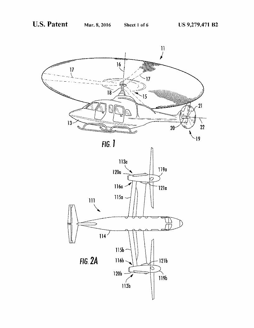
FIG. 1 is a perspective view of a helicopter, according to the present application;
FIG. 2A is a plan view of a tilt rotor aircraft, according to the present application in an airplane mode;
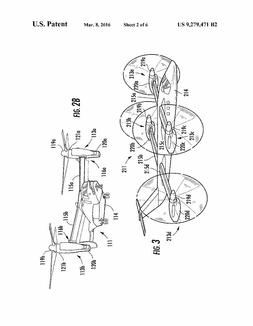
FIG. 2B is a perspective view of a tilt rotor aircraft, accord ing to the present application in a helicopter mode;
FIG. 3 is a perspective view of a quad tilt rotor aircraft, according to the present application in an airplane mode;
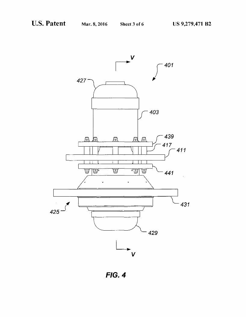
FIG. 4 is a side view of a vibration isolator, according to the preferred embodiment of the present application;
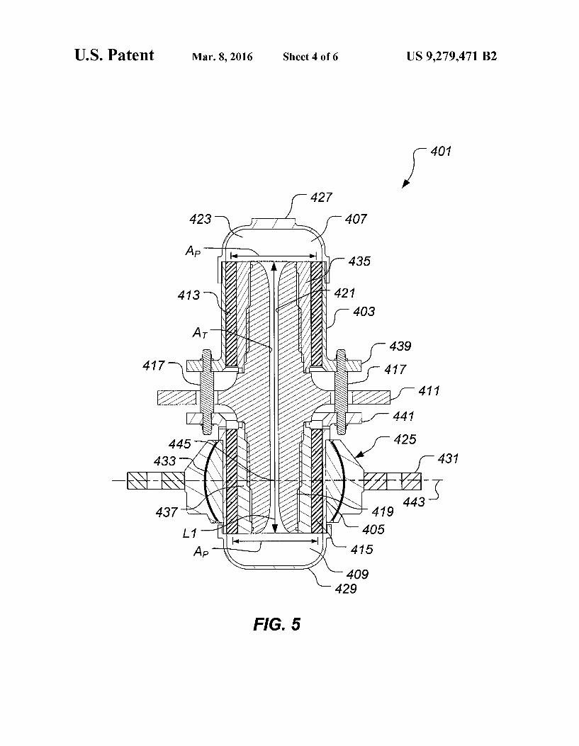
FIG. 5 is a cross-sectional view of the vibration isolator, taken from section lines V-V in FIG. 4, according to the preferred embodiment of the present application;
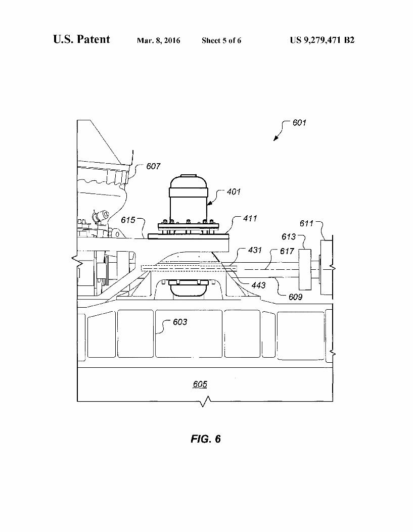
FIG. 6 is a side view of a pylon system, according to the preferred embodiment of the present application;
FIG. 7 is a mechanical equivalent force diagram of the vibration isolator of FIGS. 4 and 5; and
FIG. 8 is a schematic plan view of the pylon system of FIG. 6, according to the preferred embodiment of the present appli cation.
DESCRIPTION OF THE PREFERRED EMBODIMENT
Referring to FIG. 1 in the drawings, a helicopter 11 accord ing to the present application is illustrated. Helicopter 11 has a fuselage 13 and a main rotor assembly 15, including main rotor blades 17 and a main rotor shaft 18. Helicopter 11 has a tail rotor assembly 19, including tail rotor blades 21 and a tail rotor shaft 20. Main rotor blades 17 generally rotate about a vertical axis 16 of main rotor shaft 18. Tail rotor blades 21 generally rotate about a lateral axis 22 of tail rotor shaft 20. Helicopter 11 also includes a vibration isolation system according to the present application for isolating fuselage 13 or other portions of helicopter 11 from mechanical vibrations, Such as harmonic vibrations, which are associated with the propulsion system and which arise from the engine, transmis sion, and rotors of helicopter 11. The systems of the present application may also be utilized
on other types of rotary wing aircraft. Referring now to FIGS. 2A and 2B in the drawings, a tilt rotor aircraft 111 according to the present application is illustrated. As is conventional with tilt rotor aircraft, rotor assemblies 113a and 113b are carried by wings 115a and 115b, and are disposed at end portions 116a and 116b of wings 115a and 115b, respectively. Tilt rotor assemblies 113a and 113b include nacelles 120a and 120b, which carry the engines and transmissions of tilt rotor aircraft 111, as well as, rotor hubs 119a and 119b on forward ends 121a and 121b of tiltrotor assemblies 113a and 113b, respectively.
Tilt rotor assemblies 113a and 113b move or rotate relative to wing members 115a and 115b between a helicopter mode in which tilt rotor assemblies 113a and 113b are tilted upward, such that tilt rotor aircraft 111 flies like a conven
10
15
25
30
35
40
45
50
55
60
65
4 tional helicopter; and an airplane mode in which tilt rotor assemblies 113a and 113b are tilted forward, such that tilt rotor aircraft 111 flies like a conventional propeller driven aircraft. In FIG. 2A, tilt rotor aircraft 111 is shown in the airplane mode; and in FIG.2B, tiltrotor aircraft 111 is shown in the helicopter mode. As shown in FIGS. 2A and 2B, wings 115a and 115b are coupled to a fuselage 114. Tilt rotor air craft 111 also includes a vibration isolation system according to the present application for isolating fuselage 114 or other portions of tilt rotor aircraft 111 from mechanical vibrations, Such as harmonic vibrations, which are associated with the propulsion system and which arise from the engines, trans missions, and rotors of tilt rotor aircraft 111.
Referring now to FIG. 3 in the drawings, a quad tilt rotor aircraft 211 according to the present application is illustrated. As with the tilt rotor aircraft 111 of FIGS. 2A and 2B, rotor assemblies 213a, 213b, 213c, and 213d are carried by a for ward wing 215a, 215c, and an aft wing 215b, 215d, respec tively. Tilt rotor assemblies 213a, 213b, 213c, and 213d include nacelles 220a, 220b, 220c, and 220d, which carry the engines and transmissions of quad tilt rotor aircraft 211, as well as, rotor hubs 219a, 219b, 219C, and 219d on forward ends of tilt rotor assemblies 213a, 213b, 213c, and 213d. respectively.
Tilt rotor assemblies 213a, 213b, 213c, and 213d move or rotate relative to wing members 215a, 215b, 215c, and 215d between a helicopter mode in which tilt rotor assemblies 213a, 213b, 213c, and 213d are tilted upward, such that quad tilt rotor aircraft 211 flies like a conventional helicopter; and an airplane mode in which tilt rotor assemblies 213a, 213b, 213c, and 213d are tilted forward, such that quad tilt rotor aircraft 211 flies like a conventional propeller driven aircraft. In FIG. 3, quad tilt rotor aircraft 111 is shown in the airplane mode. As shown in FIG.3, wings 215a, 215b, 215c, and 215d are coupled to a fuselage 214. Tilt rotor aircraft 211 also includes a vibration isolation system according to the present application for isolating fuselage 214 or other portions of quad tilt rotor aircraft 211 from mechanical vibrations, such as harmonic vibrations, which are associated with the propul sion system and which arise from the engines, transmissions, and rotors of quad tilt rotor aircraft 211. It should be under stood that the systems of the present application may be used with any aircraft on which it would be desirable to have vibration isolation, including unmanned aerial vehicles that are remotely piloted.
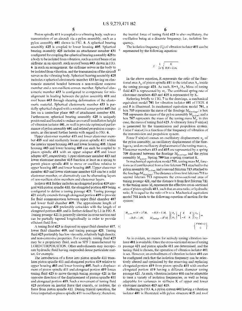
Referring now to FIGS. 4 and 5, a vibration isolator 401 according to the present application is illustrated. Isolator 401 comprises an upper housing 403 and a lowerhousing 405. An upper reservoir housing 427 and a lower reservoir housing 429 are coupled to end portions of upper housing 403 and a lower reservoir housing 405 define an upper fluid chamber 407 and a lower fluid chamber 409, respectively. A piston spindle 411 includes a cylindrical portion that is at least partially disposed within the interior of upper housing 403 and lowerhousing 405. A plurality of studs 417 rigidly couple together upper housing 403 and a lower housing 405 via an upper ring 439 and a lower ring 441, respectively, so that upper housing 403 and lowerhousing 405 function as a single rigid body. Studs 417 extend through piston spindle 411 within apertures sized to prevent any contact between studs 417 and piston spindle 411 during operation. Further, piston spindle 411 is resiliently coupled to upper housing 403 and lower housing 405 via an upper elastomer member 413 and a lower elastomer member 415, respectively. Upper elastomer member 413 and lower elastomer member 415 each function similar to a journal bearing, as further discussed herein.
US 9,279,471 B2 5
Piston spindle 411 is coupled to a vibrating body, such as a transmission of an aircraft via a pylon assembly, such as a pylon assembly 601 shown in FIG. 6. A spherical bearing assembly 425 is coupled to lower housing 405. Spherical bearing assembly 425 includes an attachment member 431 configured for coupling the spherical bearing assembly 425 to a body to be isolated from vibration, such as a roofbeam of an airframe in an aircraft, such as roofbeam 603 shown in FIG. 6. In Such an arrangement, the airframe serves as the body to be isolated from vibration, and the transmission of the aircraft serves as the vibrating body. Spherical bearing assembly 425 includes a spherical elastomeric member 433 having an elas tomeric material bonded between a non-resilient concave member and a non-resilient convex member. Spherical elas tomeric member 433 is configured to compensate for mis alignment in loading between the pylon assembly 601 and roof beam 603 through shearing deformation of the elasto meric material. Spherical elastomeric member 433 is par tially spherical shaped with a rotational centerpoint 445 that lies on a centerline plane 443 of attachment member 431. Furthermore, spherical bearing assembly 425 is uniquely positioned and located to reduce an overall installation height of vibration isolator 401, as well is provide optimized perfor mance of pylon assembly 601 and related propulsion compo nents, as discussed further herein with regard to FIG. 6.
Upper elastomer member 413 and lower elastomer mem ber 415 seal and resiliently locate piston spindle 411 within the interior upper housing 403 and lower housing 405. Upper housing 403 and lower housing 405 can each be coupled to piston spindle 411 with an upper adapter 435 and lower adapter 437, respectively. Upper elastomer member 413 and lower elastomer member 415 function at least as a spring to permit piston spindle 411 to move or oscillate relative to upper housing 403 and lower housing 405. Upper elastomer member 413 and lower elastomer member 415 can be a solid elastomer member, or alternatively can be alternating layers of non-resilient shim members and elastomer layers.
Isolator 401 further includes an elongated portion 419 inte gral with piston spindle 411, the elongated portion 419 being configured to define a tuning passage 421. Tuning passage 421 axially extends through elongated portion 419 to provide for fluid communication between upper fluid chamber 407 and lower fluid chamber 409. The approximate length of tuning passage 421 preferably coincides with the length of elongated portion 419, and is further defined by L1 in FIG. 5. Tuning passage 421 is generally circular in cross-section and can be partially tapered longitudinally in order to provide efficient fluid flow. A tuning fluid 423 is disposed in upper fluid chamber 407,
lower fluid chamber 409, and tuning passage 421. Tuning fluid 423 preferably has low viscosity, relatively high density, and non-corrosive properties. For example, tuning fluid 423 may be a proprietary fluid, such as SPF I manufactured by LORD CORPORATION. Other embodiments may incorpo rate hydraulic fluid having Suspended dense particulate mat ter, for example.
The introduction of a force into piston spindle 411 trans lates piston spindle 411 and elongated portion 419 relative to upper housing 403 and lower housing 405. Such a displace ment of piston spindle 411 and elongated portion 419 forces tuning fluid 423 to move through tuning passage 421 in the opposite direction of the displacement of piston spindle 411 and elongated portion 419. Such a movement of tuning fluid 423 produces an inertial force that cancels, or isolates, the force from piston spindle 411. During typical operation, the force imparted on piston spindle 411 is oscillatory; therefore,
10
15
25
30
35
40
45
50
55
60
65
6 the inertial force of tuning fluid 423 is also oscillatory, the oscillation being at a discrete frequency, i.e., isolation fre quency. The isolation frequency (f) of vibration isolator 401 can be
represented by the following equation:
1 K f = 3 R(R - 1)m;
In the above equation, R represents the ratio of the func tional area A of piston spindle 411 to the total area A inside the tuning passage 421. As such, R=A/A Mass of tuning fluid 423 is represented by m. The combined spring rate of elastomer members 413 and 415 is represented by K.
Referring briefly to FIG. 7 in the drawings, a mechanical equivalent model 701 for vibration isolator 401 of FIGS. 4 and 5 is illustrated. In mechanical equivalent model 701, a box 703 represents the mass of the fuselage M. : a box itselage 705 represents the mass of the pylon assembly M.; and a box 707 represents the mass of the tuning mass M, in this case, the mass of tuning fluid 423. A vibratory force F. sin(cot) is generated by the transmission and propulsion system. Force F. sin(ot) is a function of the frequency of vibration of the transmission and propulsion system.
Force F sin(cot) causes an oscillatory displacement u of the pylon assembly; an oscillatory displacement of the fuse lage u, and an oscillatory displacement of the tuning mass u. Elastomer members 413 and 415 are represented by a spring 709 disposed between the fuselage M. and the pylon assembly M. Spring 709 has a spring constant K.
In mechanical equivalent model 701, tuning mass M, func tions as ificantilevered from a first fulcrum 711 attached to the pylon assembly M and a second fulcrum 713 attached to the fuselage M. The distance a from first fulcrum 711 to second fulcrum 713 represents the cross-sectional area of tuning passage 421, and the distance b from first fulcrum 711 to the tuning mass M, represents the effective cross-sectional area of piston spindle 411. Such that an area ratio, or hydraulic ratio, R is equal to the ratio of b to a. Mechanical equivalent model 701 leads to the following equation of motion for the system:
Mylon + (R-1) M, -R (R - 1)M,
- R(R - 1)M,
As is evident, no means for actively tuning vibration iso lator 401 is available. Once the cross-sectional areas oftuning passage 421 and piston spindle 411 are determined, and the tuning fluid is chosen, the operation of vibration isolator 401 is set. However, an embodiment of vibration isolator 401 can be configured such that the isolation frequency can be selec tively altered and optimized by the removing and replacing elongated portion 419 from piston spindle 411 with another elongated portion 419 having a different diameter tuning passage 421. As such, vibration isolator 401 can be adaptable to treat a variety of isolation frequencies, as well as being adaptable for variances in stiffness K of upper and lower elastomer members 413 and 415.
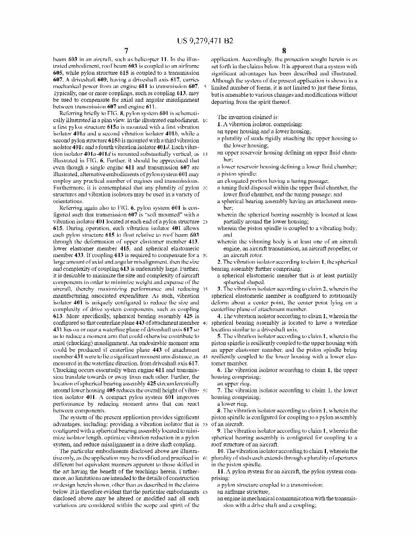
Referring to FIG. 6, a pylon system 601 having a vibration isolator 401 is illustrated with pylon structure 615 and roof
Miselage + RM,
US 9,279,471 B2 7
beam 603 in an aircraft, such as helicopter 11. In the illus trated embodiment, roof beam 603 is coupled to an airframe 605, while pylon structure 615 is coupled to a transmission 607. A driveshaft 609, having a driveshaft axis 617, carries mechanical power from an engine 611 to transmission 607. Typically, one or more couplings, such as coupling 613, may be used to compensate for axial and angular misalignment between transmission 607 and engine 611.
Referring briefly to FIG. 8, pylon system 601 is schemati cally illustrated in a plan view. In the illustrated embodiment, a first pylon structure 615a is mounted with a first vibration isolator 401a and a second vibration isolator 401b, while a second pylon structure 615b is mounted with a third vibration isolator 401 canda fourth vibration isolator 401d. Each vibra tion isolator 401a-401d is mounted substantially vertical, as illustrated in FIG. 6. Further, it should be appreciated that even though a single engine 611 and transmission 607 are illustrated, alternative embodiments of pylon system 601 may employ any practical number of engines and transmissions. Furthermore, it is contemplated that any plurality of pylon structures and vibration isolators may be used in a variety of orientations.
Referring again also to FIG. 6, pylon system 601 is con figured such that transmission 607 is “soft mounted with a vibration isolator 401 located at each end of a pylon structure 615. During operation, each vibration isolator 401 allows each pylon structure 615 to float relative to roof beam 603 through the deformation of upper elastomer member 413. lower elastomer member 415, and spherical elastomeric member 433. If coupling 613 is required to compensate for a large amount of axial and angular misalignment, then the size and complexity of coupling 613 is undesirably large. Further, it is desirable to minimize the size and complexity of aircraft components in order to minimize weight and expense of the aircraft, thereby maximizing performance and reducing manufacturing associated expenditure. As such, vibration isolator 401 is uniquely configured to reduce the size and complexity of drive system components, such as coupling 613. More specifically, spherical bearing assembly 425 is configured so that centerline plane 443 of attachment member 431 lies on or near a waterline plane of driveshaft axis 617 so as to reduce a moment arm that could otherwise contribute to axial (chucking) misalignment. An undesirable moment arm could be produced if centerline plane 443 of attachment member 431 were to lie a significant moment arm distance, as measured in the waterline direction, from driveshaft axis 617. Chucking occurs essentially when engine 611 and transmis sion translate towards or away from each other. Further, the location of spherical bearing assembly 425 circumferentially around lowerhousing 405 reduces the overall height of vibra tion isolator 401. A compact pylon system 601 improves performance by reducing moment arms that can react between components.
The system of the present application provides significant advantages, including: providing a vibration isolator that is configured with a spherical bearing assembly located to mini mize isolator length, optimize vibration reduction in a pylon system, and reduce misalignment in a drive shaft coupling. The particular embodiments disclosed above are illustra
tive only, as the application may be modified and practiced in different but equivalent manners apparent to those skilled in the art having the benefit of the teachings herein. Further more, no limitations are intended to the details of construction or design herein shown, other than as described in the claims below. It is therefore evident that the particular embodiments disclosed above may be altered or modified and all such variations are considered within the scope and spirit of the
10
15
25
30
35
40
45
50
55
60
65
8 application. Accordingly, the protection sought herein is as set forth in the claims below. It is apparent that a system with significant advantages has been described and illustrated. Although the system of the present application is shown in a limited number of forms, it is not limited to just these forms, but is amenable to various changes and modifications without departing from the spirit thereof.
The invention claimed is: 1. A vibration isolator, comprising: an upper housing and a lower housing: a plurality of studs rigidly attaching the upper housing to
the lowerhousing: an upper reservoir housing defining an upper fluid cham
ber; a lower reservoir housing defining a lower fluid chamber; a piston spindle; an elongated portion having a tuning passage; a tuning fluid disposed within the upper fluid chamber, the
lower fluid chamber, and the tuning passage; and a spherical bearing assembly having an attachment mem
ber; wherein the spherical bearing assembly is located at least
partially around the lower housing: wherein the piston spindle is coupled to a vibrating body;
and wherein the vibrating body is at least one of an aircraft
engine, an aircraft transmission, an aircraft propeller, or an aircraft rotor.
2. The vibration isolator according to claim 1, the spherical bearing assembly further comprising:
a spherical elastomeric member that is at least partially spherical shaped.
3. The vibration isolator according to claim 2, wherein the spherical elastomeric member is configured to rotationally deform about a center point, the center point lying on a centerline plane of attachment member.
4. The vibration isolator according to claim 1, wherein the spherical bearing assembly is located to have a waterline location similar to a driveshaft axis.
5. The vibration isolator according to claim 1, wherein the piston spindle is resiliently coupled to the upper housing with an upper elastomer member, and the piston spindle being resiliently coupled to the lower housing with a lower elas tomer member.
6. The vibration isolator according to claim 1, the upper housing comprising:
an upper ring. 7. The vibration isolator according to claim 1, the lower
housing comprising: a lower ring. 8. The vibration isolator according to claim 1, wherein the
piston spindle is configured for coupling to a pylon assembly of an aircraft.
9. The vibration isolator according to claim 1, wherein the spherical bearing assembly is configured for coupling to a roof structure of an aircraft.
10. The vibration isolator according to claim 1, wherein the plurality of studs each extends through a plurality of apertures in the piston spindle.
11. A pylon system for an aircraft, the pylon system com prising:
a pylon structure coupled to a transmission; an airframe structure; an engine in mechanical communication with the transmis
sion with a drive shaft and a coupling;

US 9,279,471 B2 9
a vibration isolator coupled between the pylon structure and the airframe structure, the vibration isolator com prising: an upper housing and a lower housing: a plurality of studs rigidly attaching the upper housing to
the lower housing: an upper reservoir housing defining an upper fluid cham
ber; a lower reservoir housing defining a lower fluid cham
ber; a piston spindle; an elongated portion having a tuning passage; a tuning fluid disposed within the upper fluid chamber,
the lower fluid chamber, and the tuning passage; and a spherical bearing assembly with an attachment mem
ber; wherein the spherical bearing assembly of the vibration
isolator is located near a waterline location of a rota tional axis of the drive shaft; and
wherein the spherical bearing assembly is located at least partially around the lower housing of the vibration iso lator.
12. The pylon system according to claim 11, the spherical bearing assembly of the vibration isolator further comprising:
a spherical elastomeric member that is at least partially spherical shaped.
13. The pylon system according to claim 12, wherein the spherical elastomeric member is configured to rotationally deform about a center point, the center point lying on a centerline plane of attachment member.
14. The pylon system according to claim 11, wherein the piston spindle is resiliently coupled to the upper housing with an upper elastomer member, and the piston spindle being resiliently coupled to the lower housing with a lower elas tomer member.
15. The pylon system according to claim 11, wherein the transmission is a vibrating body.
10
15
25
30
35
10 16. The pylon system according to claim 11, wherein the
plurality of studs each extends through apertures in the piston spindle; and
wherein the apertures in the piston spindle are sized to prevent contact between the plurality of studs and the piston spindle during operation of the aircraft.
17. The pylon system according to claim 11, wherein the location of the spherical bearing assembly minimizes mis alignment in the coupling.
18. The pylon system according to claim 11, wherein the location of the spherical bearing assembly minimizes chuck ing in the coupling.
19. The pylon system according to claim 11, wherein the coupling is located between the engine and the transmission.
20. A vibration isolator, comprising: an upper housing having an upper ring: a lower housing having a lower ring; a plurality of studs rigidly attaching the upper ring to the
lower ring; an upper reservoir housing defining an upper fluid cham
ber; a lower reservoir housing defining a lower fluid chamber; a piston spindle having a plurality of apertures; an elongated portion having a tuning passage; a tuning fluid disposed within the upper fluid chamber, the
lower fluid chamber, and the tuning passage; and a spherical bearing assembly having an attachment mem
ber; wherein the apertures isolate the piston spindle from the
plurality of studs: wherein the spherical bearing assembly is located at least
partially around the lower housing: wherein the piston spindle is coupled to a vibrating body;
and wherein the vibrating body is at least one of an aircraft
engine, an aircraft transmission, an aircraft propeller, or an aircraft rotor.