Embed Size (px)
Citation preview
GRID MODERNIZATION INITIATIVE
HELICS1.4.15 - Development of Integrated Transmission,
Distribution and Communication (TDC) Models
HENRY HUANG
7/26/2017 1
July 21, 2017
Presented at the SunShot SuNLaMP Workshop, ANL
Design and Planning Tools
7/26/2017 2
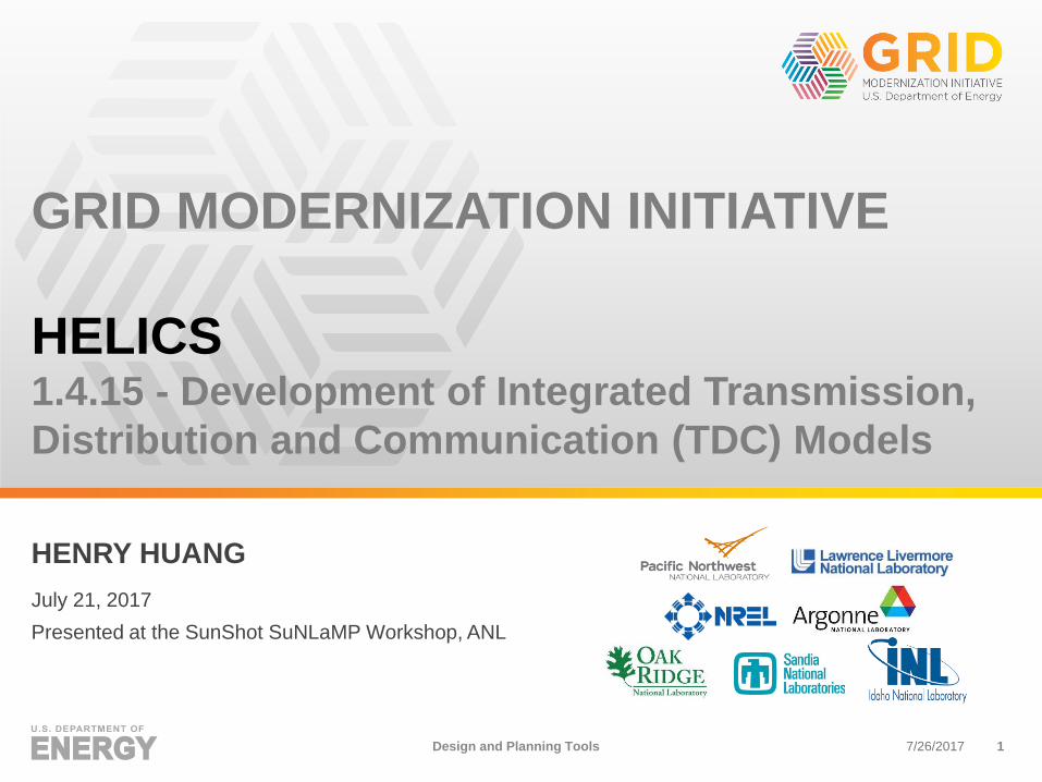
► TRC webinar
► TRC in-person meeting
GMLC 1.4.15 TDC Models:
Extensive industry engagement
Design and Planning Tools
7/26/2017 3
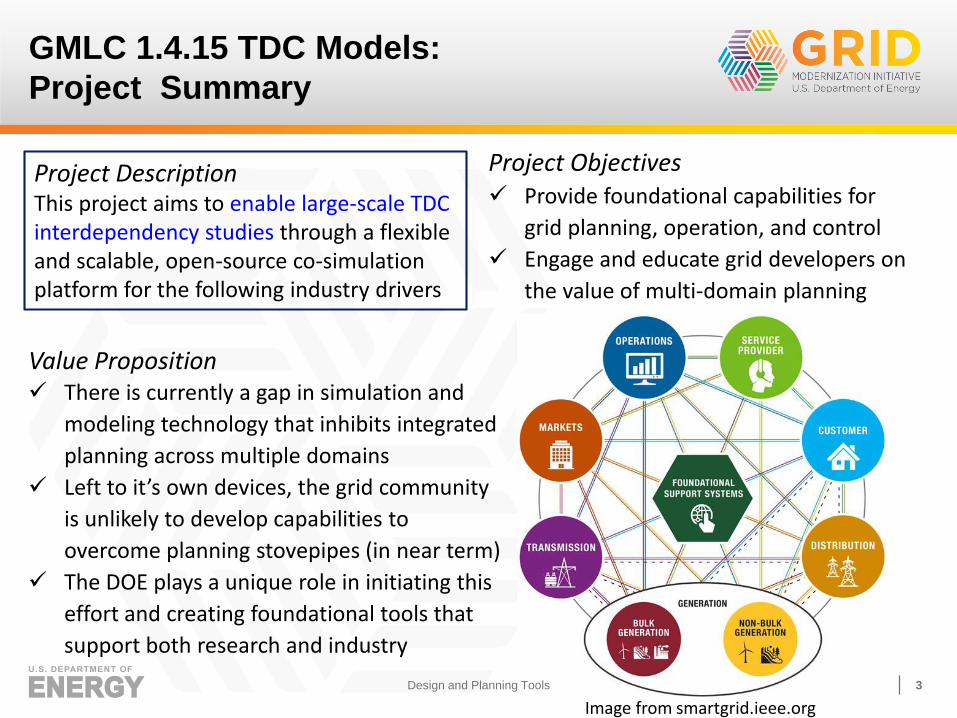
Project DescriptionThis project aims to enable large-scale TDC interdependency studies through a flexible and scalable, open-source co-simulation platform for the following industry drivers
Value Proposition There is currently a gap in simulation and
modeling technology that inhibits integrated
planning across multiple domains
Left to it’s own devices, the grid community
is unlikely to develop capabilities to
overcome planning stovepipes (in near term)
The DOE plays a unique role in initiating this
effort and creating foundational tools that
support both research and industry
Project Objectives Provide foundational capabilities for
grid planning, operation, and control
Engage and educate grid developers on
the value of multi-domain planning
GMLC 1.4.15 TDC Models:
Project Summary
Image from smartgrid.ieee.org
Design and Planning Tools
7/26/2017 4
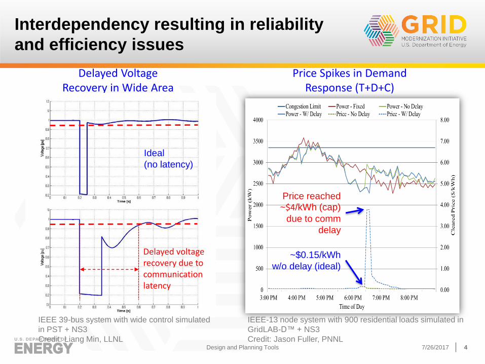
Interdependency resulting in reliability
and efficiency issues
Delayed Voltage Recovery in Wide Area
Control (T+C)
Delayed voltage recovery due to communication latency
~$0.15/kWh
w/o delay (ideal)
Price reached ~$4/kWh (cap)
due to comm
delay
Price Spikes in Demand Response (T+D+C)
IEEE-13 node system with 900 residential loads simulated in
GridLAB-D™ + NS3
Credit: Jason Fuller, PNNL
Ideal
(no latency)
IEEE 39-bus system with wide control simulated
in PST + NS3
Credit: Liang Min, LLNLDesign and Planning Tools
7/26/2017 5
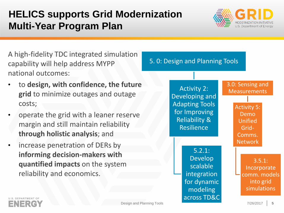
A high-fidelity TDC integrated simulation capability will help address MYPP national outcomes:
• to design, with confidence, the future grid to minimize outages and outage costs;
• operate the grid with a leaner reserve margin and still maintain reliability through holistic analysis; and
• increase penetration of DERs by informing decision-makers with quantified impacts on the system reliability and economics.
HELICS supports Grid Modernization
Multi-Year Program Plan
5. 0: Design and Planning Tools
Activity 2: Developing and Adapting Tools for Improving Reliability & Resilience
5.2.1: Develop scalable
integration for dynamic
modeling across TD&C
3.0: Sensing and Measurements
Activity 5: Demo
Unified Grid-
Comms. Network
3.5.1: Incorporate
comm. models into grid
simulations
Design and Planning Tools
7/26/2017 6
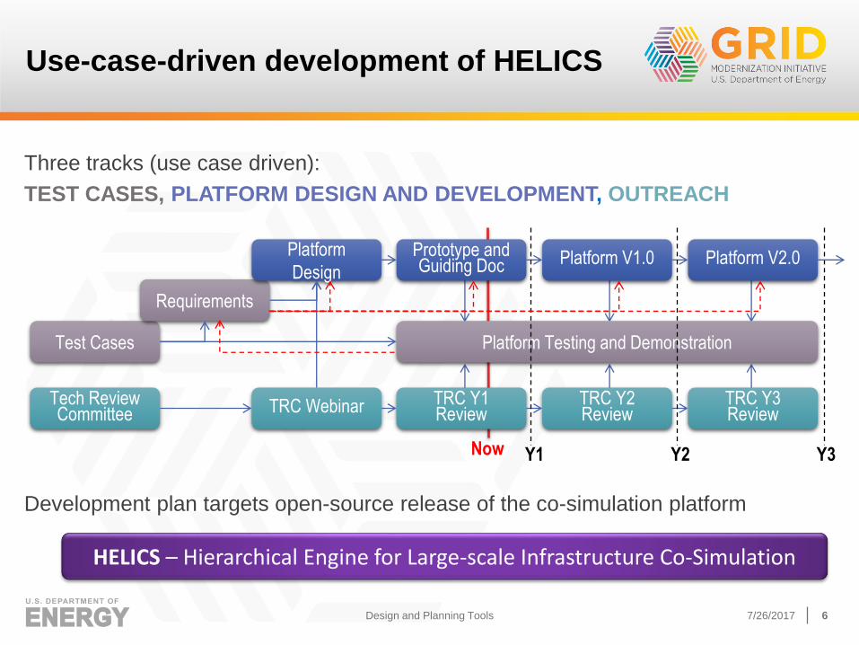
Three tracks (use case driven):
TEST CASES, PLATFORM DESIGN AND DEVELOPMENT, OUTREACH
Development plan targets open-source release of the co-simulation platform
Use-case-driven development of HELICS
Test Cases
Requirements
Platform
Design
Prototype and Guiding Doc Platform V1.0 Platform V2.0
Platform Testing and Demonstration
Tech Review Committee TRC Webinar TRC Y1
ReviewTRC Y2 Review
TRC Y3 Review
Y1 Y2 Y3Now
HELICS – Hierarchical Engine for Large-scale Infrastructure Co-Simulation
Design and Planning Tools
7/26/2017 7
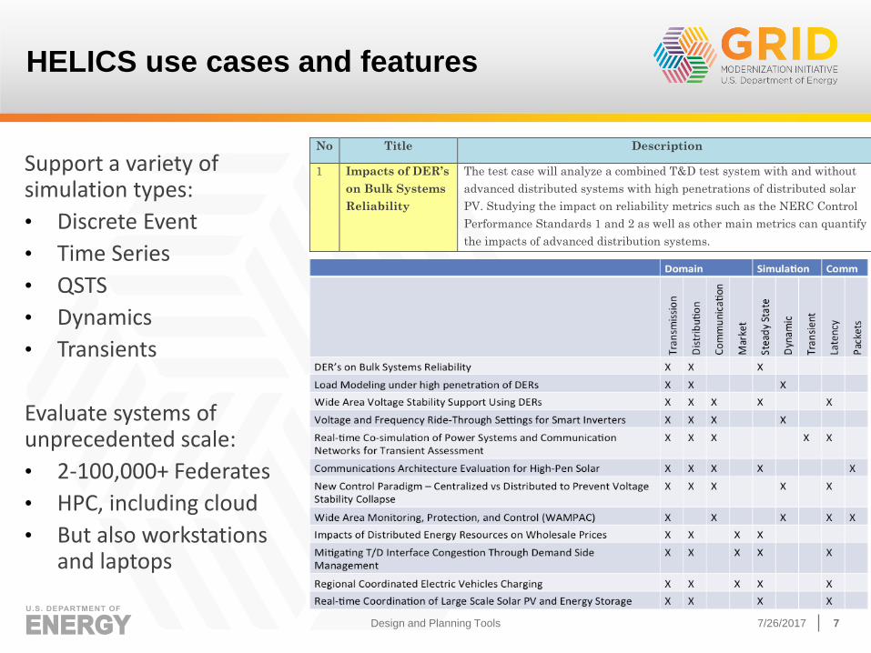
HELICS use cases and features
No Title Description
1 Impacts of DER’s
on Bulk Systems
Reliability
The test case will analyze a combined T&D test system with and without
advanced distributed systems with high penetrations of distributed solar
PV. Studying the impact on reliability metrics such as the NERC Control
Performance Standards 1 and 2 as well as other main metrics can quantify
the impacts of advanced distribution systems.
Design and Planning Tools
Support a variety of simulation types:
• Discrete Event
• Time Series
• QSTS
• Dynamics
• Transients
Evaluate systems of unprecedented scale:
• 2-100,000+ Federates
• HPC, including cloud
• But also workstations and laptops
7/26/2017 8
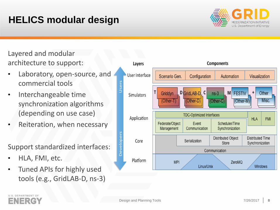
HELICS modular design
Design and Planning Tools
Layered and modular architecture to support:
• Laboratory, open-source, and commercial tools
• Interchangeable time synchronization algorithms (depending on use case)
• Reiteration, when necessary
Support standardized interfaces:
• HLA, FMI, etc.
• Tuned APIs for highly used tools (e.g., GridLAB-D, ns-3)
7/26/2017 9
HELICS development status and next steps
• Developed 12 use cases, with broad coverage
• Released v0.1 of HELICS to the open source in May 2017, including Guiding Document and example use cases
• Currently securing licensing and copyright agreements
• Held TRC Meeting in May 2017 in Richland, WA
• Add additional simulators as identified by working with other GMLC projects and TRC members
• Implement HPC Platform Layer (MPI-based) to address large numbers of federates
• Develop use cases to demonstrate value and address limits of tool
• Develop (and release) tools to increase usability of tool
• Release subsequent versions to open source (Ver 1, 12/1/2017)
Design and Planning Tools
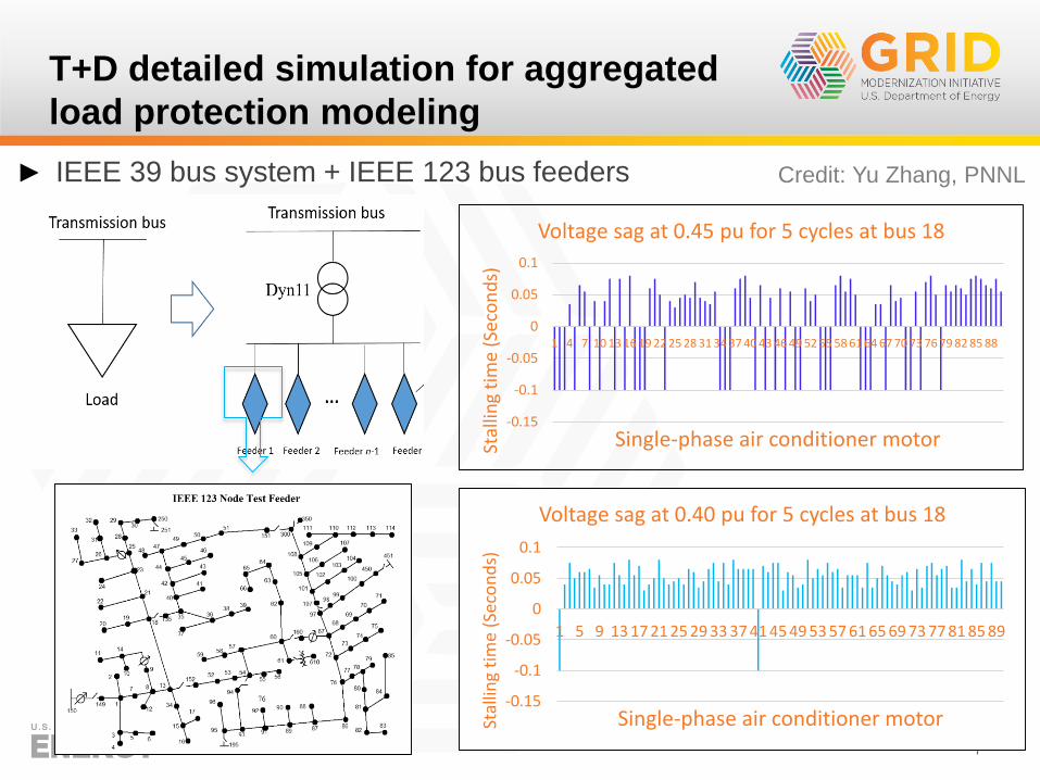
T+D detailed simulation for aggregated
load protection modeling
► IEEE 39 bus system + IEEE 123 bus feeders
10
-0.15
-0.1
-0.05
0
0.05
0.1
1 4 7 10 13 16 19 22 25 28 31 34 37 40 43 46 49 52 55 58 61 64 67 70 73 76 79 82 85 88
Stal
ling
tim
e (S
eco
nd
s)
Single-phase air conditioner motor
Voltage sag at 0.45 pu for 5 cycles at bus 18
-0.15
-0.1
-0.05
0
0.05
0.1
1 5 9 13 17 21 25 29 33 37 41 45 49 53 57 61 65 69 73 77 81 85 89
Stal
ling
tim
e (S
eco
nd
s)
Single-phase air conditioner motor
Voltage sag at 0.40 pu for 5 cycles at bus 18
Credit: Yu Zhang, PNNL
11
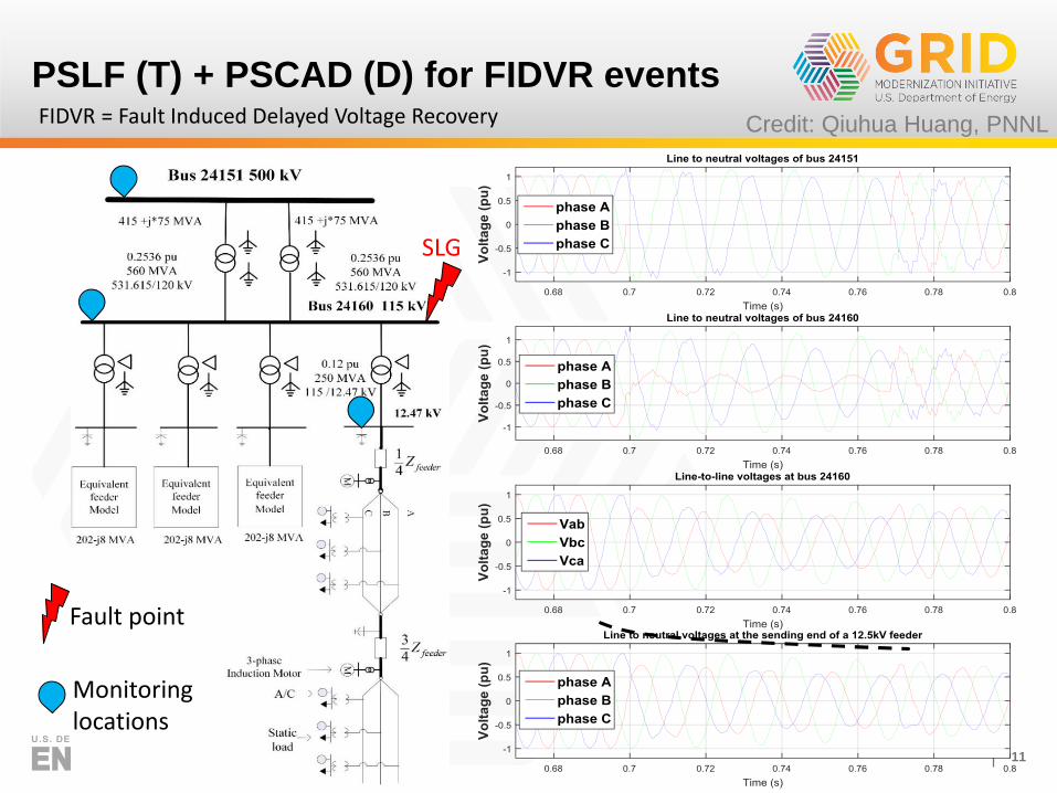
PSLF (T) + PSCAD (D) for FIDVR events
Fault point
Monitoring locations
SLG
FIDVR = Fault Induced Delayed Voltage Recovery Credit: Qiuhua Huang, PNNL
12
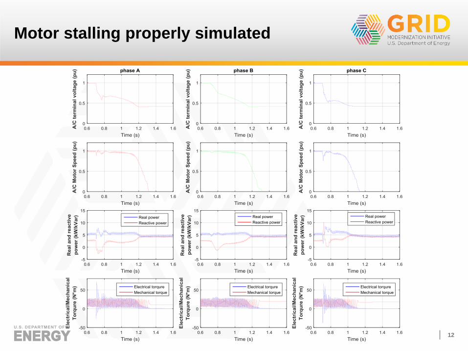
Motor stalling properly simulated
13
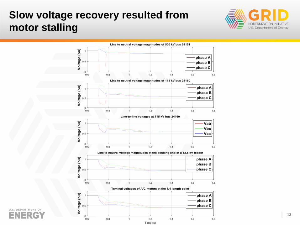
Slow voltage recovery resulted from
motor stalling
14
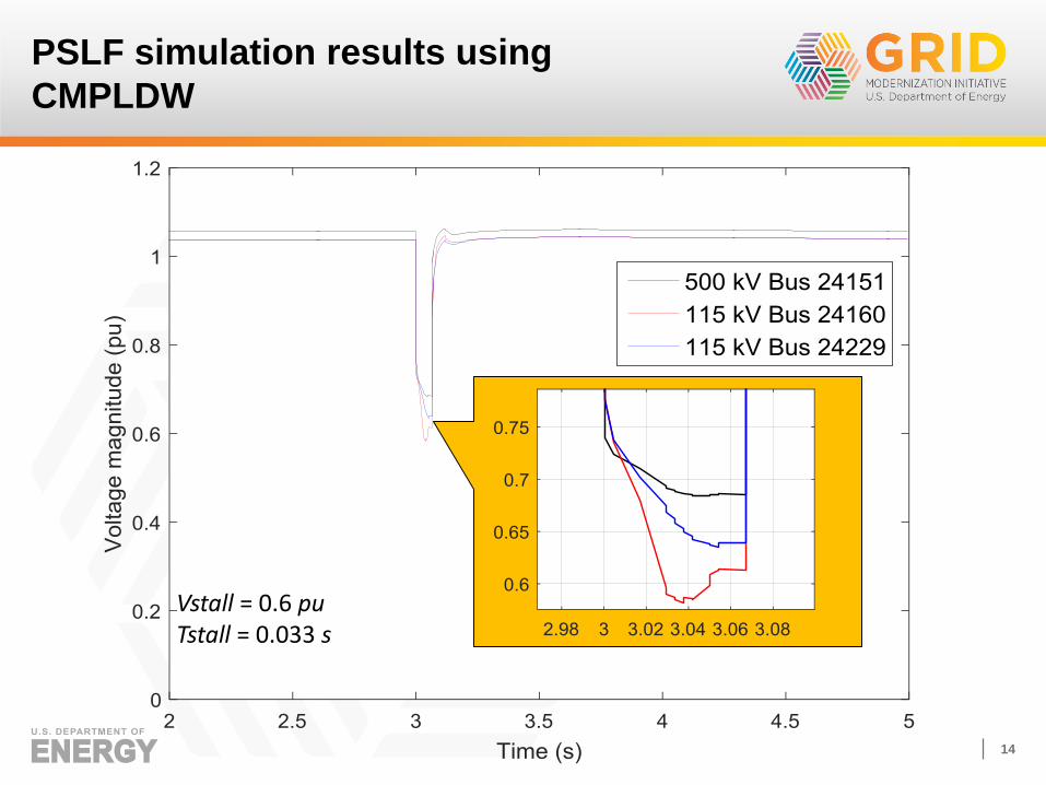
PSLF simulation results using
CMPLDW
Vstall = 0.6 puTstall = 0.033 s