Embed Size (px)
Citation preview

Grid-Connected Photovoltaic System Design Review and
Approval
Author
FSEC PVDG Division
Publication Number FSEC-GP-70-01
Copyright Copyright © Florida Solar Energy Center/University of Central Florida
1679 Clearlake Road, Cocoa, Florida 32922, USA (321) 638-1000
All rights reserved.
Disclaimer
The Florida Solar Energy Center/University of Central Florida nor any agency thereof, nor any of their employees, makes any warranty, express or implied, or assumes any legal liability or responsibility for the accuracy, completeness, or usefulness of any information, apparatus, product, or process disclosed, or represents that its use would not infringe privately owned rights. Reference herein to any specific commercial product, process, or service by trade name, trademark, manufacturer, or otherwise does not necessarily constitute or imply its endorsement, recommendation, or favoring by the Florida Solar Energy Center/University of Central Florida or any agency thereof. The views and opinions of authors expressed herein do not necessarily state or reflect those of the Florida Solar Energy Center/University of Central Florida or any agency thereof.

Photovoltaic System Design Review and Approval, FSEC-GP-70-01 Page 1
Grid-Connected Photovoltaic System Design Review and Approval Operations and Procedures
Florida Solar Energy Center
1679 Clearlake Road Cocoa, Florida 32922-5703
FSEC-GP-70-01
Procedure # 7003 Version 6 – April 23, 2003
1. INTRODUCTION................................................................................................................................................................3 1.1 QUALIFYING STATUS...................................................................................................................................................... 3 1.2 SCOPE............................................................................................................................................................................... 3
2. SYSTEM CLASSIFICATIO NS .......................................................................................................................................4 2.1 GRID-CONNECTED PV SYSTEMS WITHOUT BATTERY STORAGE............................................................................. 4 2.2 GRID-CONNECTED PV SYSTEMS WITH BATTERY STORAGE.................................................................................... 4
3. CRITERIA FOR SYSTEM APPROVAL......................................................................................................................5
4. APPLICATION FOR DESIGN REVIEW ....................................................................................................................5
5. EVALUATION PROCESS................................................................................................................................................6 5.1 SYSTEM DOCUMENTATION REVIEW ............................................................................................................................ 6 5.2 ELECTRICAL DESIGN EVALUATION.............................................................................................................................. 6 5.3 MECHANICAL DESIGN EVALUATION........................................................................................................................... 7 5.4 PV MODULES AND ARRAYS.......................................................................................................................................... 7 5.5 POWER CONDITIONING EQUIPMENT............................................................................................................................. 7 5.6 DESIGN REVIEW AND APPROVAL PROCESS ................................................................................................................ 8
6. ADMINISTRATION...........................................................................................................................................................9 6.1 PERSONNEL...................................................................................................................................................................... 9 6.2 RECORD KEEPING........................................................................................................................................................... 9 6.3 FEES .................................................................................................................................................................................. 9 6.4 USE OF SYSTEM APPROVAL .......................................................................................................................................... 9 6.5 MAINTAINING SYSTEM APPROVALS.......................................................................................................................... 10
6.5.1 Denial of Approval..............................................................................................................................................10 6.5.2 Revocation of Approval......................................................................................................................................10
6.5.2.1 Supplier-initiated................................................................................................................................................ 10 6.5.2.2 FSEC-initiated.................................................................................................................................................... 10
7. GLOSSARY.........................................................................................................................................................................11
8. REFERENCE DOCUMENTS ........................................................................................................................................14
9. APPENDIX...........................................................................................................................................................................15 9.1 DESIGN REVIEW APPLICATION FORM........................................................................................................................ 15 9.2 DESIGN REVIEW CHECKLIST AND REPORTING FORM ............................................................................................. 16
SYSTEM DOCUMENTATION ..............................................................................................................................................16
ELECTRICAL DESIGN ...........................................................................................................................................................17 GENERAL DOCUMENTATION.................................................................................................................................................... 17 DC CONDUCTORS & CONDUIT ................................................................................................................................................ 17
A. Wire Type: Specifies appropriate types, sizes and ratings and locations for all system conductors and wiring ..............................17

Photovoltaic System Design Review and Approval, FSEC-GP-70-01 Page 2
B. Ampacity Calculations (current rating) Including De-rating Values for Temperature & Multiple Conductors..................................................................................................................................................................................................17 C. Conduit Fill.......................................................................................................................................................................17 D. Conduit Type & Coupling/Connectors........................................................................................................................17 E. Voltage Calculations (voltage rating)..........................................................................................................................18 F. Voltage Drop ....................................................................................................................................................................18
AC CONDUCTORS & CONDUIT ................................................................................................................................................ 18 A. Wire Type ..........................................................................................................................................................................18 B. Ampacity Calculations (current sizing) Including De-rating Values for Temperature & Multiple Conductors..................................................................................................................................................................................................18 C. Conduit Fill.......................................................................................................................................................................18 D. Conduit Type & Coupling/Connectors........................................................................................................................18 E. Voltage Calculations (voltage sizing)..........................................................................................................................19
OVERCURRENT PROTECTION & DISCONNECTS..................................................................................................................... 19 A. Fuses ..................................................................................................................................................................................19 B. Disconnects – Circuit Breakers.....................................................................................................................................19
GROUNDING................................................................................................................................................................................ 19 JUNCTION BOXES ....................................................................................................................................................................... 19 SERVICE PANEL .......................................................................................................................................................................... 19
MECHANICAL DESIGN .........................................................................................................................................................20
COMPONENT INFORMATION...........................................................................................................................................21 PV MODULES AND ARRAY....................................................................................................................................................... 21
AN IMPORTANT PART OF THE SYSTEM APPROVALS IS TO ENSURE THAT QUALITY PV MODULES ARE USED FOR INSTALLATIONS. BASIC REQUIREMENTS INCLUDE APPLICABLE QUALIFICATION TESTS AND PRODUCT LISTINGS, AS WELL AS MANUFACTURERS SPECIFICATIONS AND PERFORMANCE RATINGS. ..................................................................21
POWER CONDITIONING EQUIPMENT........................................................................................................................................ 21 BATTERIES & CHARGE CONTROLLERS................................................................................................................................... 22 9.3 EXAMPLE SYSTEM APPROVAL CERTIFICATE............................................................................................................ 23

Photovoltaic System Design Review and Approval, FSEC-GP-70-01 Page 3
1. Introduction This document provides details of operations and procedures for the approval of grid-connected photovoltaic (PV) system designs and documentation conducted by the Florida Solar Energy Center. The principal goal of this process is to help ensure the safety and quality of installed PV systems, and provides an assurance to installers, consumers and financiers that approved designs meet accepted codes and industry practices, and are accompanied by a complete System Manual that meets the minimum requirements outlined in this document.
1.1 Qualifying Status Under the Solar Energy Standards Act of 1976, Florida Statutes 377.705, The Florida Solar Energy Center (FSEC) is mandated to set standards, conduct tests and evaluations, and to certify solar energy systems and equipment manufactured or sold in the State of Florida. For over twenty years, FSEC has developed and maintained standards, testing capabilities and equipment certification programs for solar water and pool heating equipment. FSEC has also been heavily involved in the development, testing, and evaluation of PV systems and equipment, regularly participating in national research and standards development efforts. In recent years, increased subsidies, advancements in equipment and the technology, and reductions in price have resulted in numerous applications and increasing markets for grid-connected PV systems on residential and commercial buildings. As part of an existing rebate program for PV installations in Florida and associated quality assurance requirements, all grid-connected PV system designs installed under this program must undergo a design review process and gain this approval to qualify for rebate funds. Note that these approvals are only required for the Florida rebate program, and do not supercede or replace any requirements associated with permitting or inspection of installations in Florida or any other states. However, other states and programs implementing quality assurance measures for PV installations may use information regarding FSEC-approved PV system packages. In 2001, FSEC received two important accreditations pursuant to the review of PV system designs and approvals. The first, awarded by American Association of Laboratory Accreditation (A2LA), recognizes FSEC for following the quality systems requirements of ISO/IEC 17025 - General Requirements for the Competence of Testing and Calibration Laboratories. The second, awarded by PowerMark Corporation, recognizes FSEC specifically for following procedures outlined in PowerMark document PV 3.3: Design and Documentation Review and Evaluation Requirements for Grid-tied Residential and Small Commercial PV Systems, as a component of the PowerMark Photovoltaic Certification and Labeling Program. As part of maintaining these accreditations, FSEC routinely undergoes audits, and on-site review of procedures, records, reports, accounting and other matters related to conducting these reviews and granting PV system approvals.
1.2 Scope This procedure applies to any type of photovoltaic system interconnected with the utility grid and provides a means for evaluating the complete design and documentation package. Items evaluated include safety and code compliance of the overall design, individual components and their interactions with one another, and the completeness of the instructions, diagrams and schematics for the installation, operation and maintenance of the system. This review and approval procedure does not cover site-specific requirements or issues, nor do these approvals replace or exempt any requirements of electric utilities or local jurisdictional authorities such as permitting, inspections or utility interconnection agreements as required for PV system installations.

Photovoltaic System Design Review and Approval, FSEC-GP-70-01 Page 4
2. System Classifications Two types of grid-connected photovoltaic systems are considered in the Grid-Connected Photovoltaic System Design Review and Approval process. These include 1) Grid-Connected PV Systems without Battery Storage, and 2) Grid-Connected PV Systems with Battery Storage. For the purposes of this document and the scope of the design review and approval process, the following is the intended definition of a grid-connected photovoltaic system: “An electrical power generating system that uses a photovoltaic (PV) array as the primary source of electricity generation, and is intended to operate synchronously and in parallel with the electric utility network. Such systems may also include battery storage, other generating sources, and may operate on site loads independent of the utility network during outages.”
2.1 Grid-Connected PV Systems without Battery Storage Grid-connected or utility-interactive PV systems are designed to operate in parallel with and interconnected to the electric utility grid. The primary component in grid-connected PV systems is the inverter, or power-conditioning unit (PCU). The PCU converts the DC power produced by the PV array into AC power consistent with the voltage and power quality requirements of the utility grid, and automatically stops supplying power to the grid when the utility grid is not energized. A bi-directional interface is made between the PV system AC output circuits and the electric utility network, typically at the on-site distribution panel or service entrance. This allows the AC power produced by the PV system to either supply on-site electrical loads, or to back feed the grid when the PV system output is greater than the on-site load demand. At night and during other periods when the electrical loads are greater than the PV system output, the balance of power required by the loads is received from the electric utility. When the utility grid is down, these systems automatically shut down and disconnect from the grid. This safety feature is required in all grid-connected PV systems, and ensures that the PV system will not continue to operate and feed back onto the utility grid when the grid is down for service or repair.
2.2 Grid-Connected PV Systems with Battery Storage This type of system is extremely popular for homeowners and small businesses where backup power is required for critical loads such as refrigeration, water pumps, lighting and other necessities. Under normal circumstances, the system operates in a grid-connected mode, supplementing the on-site loads or sending excess power back onto the grid while keeping the battery fully charged. In the event the grid becomes de-energized, control circuitry in the inverter opens the connection with the utility through a bus transfer mechanism, and operates the inverter from the battery to supply power to the dedicated critical load circuits only. In this configuration, critical loads are typically supplied from a dedicated load sub panel.
PV Array
Inverter/Power Conditioner
BatteryStorage
Critical LoadSub Panel
CriticalAC Loads
Main Panel
Non-CriticalAC Loads
ElectricUtility
DistributionPanel
PV Array Inverter/Power Conditioner
AC Loads
ElectricUtility
Photovoltaic System Design Review and Approval, FSEC-GP-70-01 Page 5
3. Criteria for System Approval Criteria for system approvals are based on applicable codes and standards, and consistency with industry accepted design practices. Evidence to support these criteria must be contained in the supplier’s System Manual. General criteria include: § Conformance of the overall electrical design and specified installation methods with all relevant sections of the
2002 National Electrical Code. § Evidence of applicable product listings for major components from Underwriters Laboratory (UL) or other
recognized laboratory. PV modules must meet current versions of UL Std. 1703 for Flat Plate Photovoltaic Modules and Panels, and inverters and charge controllers must meet UL Std. 1741 for Inverters, Converters and Controllers for use in Independent Power Systems.
§ Evidence of PV module qualification tests consistent with the standards: § IEEE 1262 - Recommended Practice for Qualification of Photovoltaic (PV) Modules, or § IEC 61215 - Crystalline Silicon Terrestrial Photovoltaic (PV) Modules - Design Qualification and Type
Approval. § Ratings for PV module performance conducted by FSEC or other independent recognized laboratory. § Conformance of overall system design and installation requirements with § IEEE Std. 929 - Recommended Practice for Utility Interface of Photovoltaic (PV) Systems and § IEEE Std. 1374 - Guide for Terrestrial Photovoltaic Power System Safety.
§ Where battery storage is used, conformance with (as applicable) § IEEE Std. 937-2000: Recommended Practice for Installation and Maintenance of Lead-Acid Batteries for
Photovoltaic (PV) Systems § IEEE 1145 - IEEE Recommended Practice for the Installation and Maintenance of Nickel-Cadmium
Batteries for Photovoltaic (PV) Systems § Evidence of independent test results or certification from a licensed engineer certifying that the array mounting
system design is capable of adequately supporting the modules within specified deflection limits under loading conditions of at least 55 lbs/ft.
§ Warranty information for complete system and individual components. 4. Application for Design Review Any system integrator, supplier or installation contractor may initiate the design review process by completing an application form and submitting all required documentation and materials to FSEC for review. A single application may be used for multiple size systems of a basic type or model, as long as each system model is indicated on the application, and these designs are adequately documented in the System Manual. Any manufacturer, system integrator or organization requesting design review and approval should use the Photovoltaic System Design Review and Approval: Application Form and Checklist as a guide for submitting the required System Manual. The application form and checklist for submitting designs for review are include in the Appendix, and are also available from FSEC’s web site at: http://www.fsec.ucf.edu/pvt/ The organization or individual submitting the design for approval will be responsible for meeting all criteria on the checklist by providing the necessary documentation, drawings, schematics, parts lists, manuals, and warranty documentation. The initial system design review process will typically be completed within six weeks of formal submission to FSEC. Items that are incomplete or inaccurate required will be identified for the applicant, and the designs will be appropriately amended by the applicant prior to approval.

Photovoltaic System Design Review and Approval, FSEC-GP-70-01 Page 6
5. Evaluation Process System manuals, electrical and mechanical drawings, component manuals and other documentation submitted for review will be evaluated according to the requirements of this document. When the review is completed, FSEC will provide the supplier with a report on the evaluation, and note any deficiencies required for approval. After all deficiencies have been resolved, approval will be granted and the supplier will be awarded a System Approval Certificate.
5.1 System Documentation Review A complete system documentation package is a fundamental requirement for system approvals. At a minimum, this documentation must include system specifications, parts lists, electrical schematics, mechanical drawings, and instructions for the installation, operation and maintenance of the system. The supplied documentation is reviewed to verify that the following items are included: § System description and specifications § Parts and source lists for equipment supplied and not supplied with package § Electrical diagrams and schematics § Mechanical drawings and panel/array installation detail § System installation and checkout procedures § System operation, maintenance and troubleshooting instructions § Owners manuals for individual major components § Warranty information on components and complete system
5.2 Electrical Design Evaluation Safe and code-compliant electrical designs are a principal concern of these approvals, and must be consistent with the requirements of the 2002 National Electrical Code. At a minimum, supplier's electrical drawings must include the types, sizes, ratings and locations of all conductors, overcurrent and disconnect devices, terminations and connectors, conduit and junction boxes, and grounding systems. Complete electrical schematics are required for these items. Design documentation, installation instructions and electrical schematics are reviewed to verify that they specify and diagram: § Types, sizes and locations of all system conductors § Types, ratings and locations for all required system disconnect and overcurrent devices § Ratings and locations for blocking and bypass diodes, as applicable § Requirements for equipment and system grounding and surge suppression § Methods and equipment required to interface the PV system output with the electric utility grid § Types, ratings and locations for all conduit and junction boxes § DC voltage drop limitations and conductors required for given length

Photovoltaic System Design Review and Approval, FSEC-GP-70-01 Page 7
5.3 Mechanical Design Evaluation Methods for the safe, secure and durable attachment of PV arrays to rooftops or other support is an essential part of the complete design package. At a minimum, supplier’s documentation and drawings must include details for assembling module/panels, layouts for the entire array, making structural connections to rooftops, and weather sealing roof penetrations. Independent laboratory test results or certification from a licensed engineer must be provided for mechanical loads on PV arrays and mounting systems. Note that additional structural certifications from a licensed engineer may be required in many jurisdictions for permitting actual installations. The documentation and drawings are reviewed to verify that the following items are included: § Procedures and materials required for assembling modules and panels § Procedures and materials for making structural attachments to rooftops § Procedures for locating and orienting arrays on rooftop § Methods and materials for weather sealing roof penetrations § Safety considerations for installing PV array on rooftops § Independent test results or certification for mechanical loads on PV array and support structures
5.4 PV Modules and Arrays An important part of the system design reviews is ensuring that quality PV modules are used. Basic requirements include applicable qualification tests and product listings, and manufacturers’ specifications. Independent performance tests (conducted by FSEC or other accredited lab) are also required for system approvals. Documentation submitted for review is evaluated to verify that: § PV modules comply with IEEE Standard 1262 or IEC Std 61215 qualification test standard § PV modules comply with UL Standard 1703 product listing § Methods and materials for assembling and wiring modules, panels and arrays are described and diagrammed § STC ratings for PV modules, panels and entire array are specified § Locations for bypass diodes are specified § Procedures for handling and installing modules and arrays are provided § Module manufacturers documentation is included
5.5 Power Conditioning Equipment Inverters, chargers, controllers and other power processing hardware are critical components in these approvals, and this equipment must meet industry standards for grid-connected PV systems. Acceptable voltage set points, and other system programming or control set points must also be consistent for the type of batteries used, as applicable. The system documentation and equipment specifications are reviewed for: § Compliance with current standards UL 1741 and IEEE 929 § Specification and appropriateness of inverter/controller operating windows for PV array under highest and
lowest temperature extremes § Specification and appropriateness of control or programmable set points for charge control with given battery § Inclusion of owner’s, operator’s and user’s manuals for all major power processing components

Photovoltaic System Design Review and Approval, FSEC-GP-70-01 Page 8
5.6 Design Review and Approval Process • Application for Design Review and Approval Received at
FSEC, date and submitted materials recorded • Review documents distributed to FSEC Design Review
Committee (DRC)
• Verification hat all information and documents required for the application and in the Design Review and Approval Checklist are present.
• Application returned with request for missing information.
• DRC evaluation of materials submitted, in accordance with FSEC Document GP-70-01
• Completion of Design Review and Approval Checklist
NO YES
• Final application review meeting by all members of DRC • Individual review compiled and discussed
• Approval decision made
• Approval denied • Reasons for denying
approval documented in writing to applicant.
• Application returned
• Approval granted • Applicant advised of requirements
for use and maintaining approval per FSEC Document GP-70-01
• Approval listed in Approved Systems directory on FSEC’s web site
• Deficiencies noted • Requirements for
resubmission identified in writing to applicant
• Application returned to applicant

Photovoltaic System Design Review and Approval, FSEC-GP-70-01 Page 9
6. Administration
6.1 Personnel A Design Review Committee (DRC) consisting of designated FSEC staff members evaluates all submittals. DRC members are all experts in the field and have cumulative experience of over fifty years in the design, operation and evaluation of grid-connected PV systems. The DRC consists of the following five FSEC staff members and alternate: Brian Farhi (Chair) Gerard Ventre, Ph.D., P.E. Gobind Atmaram, Ph.D. James Dunlop, P.E. Kevin Lynn William Wilson (Alternate) All DRC members and alternate are committed to objectivity, impartiality and fairness in the reviews, in the overall quality of the process, and in maintaining requirements of FSEC’s accreditation governing these reviews and approvals.
6.2 Record Keeping Documentation and archives for all correspondence are kept electronically and in hardcopy in the file room in the FSEC PVDG Division.
6.3 Fees At present, there are no fees charged for the PV System Design Review and Approval process. This system approval program is currently conducted on a voluntary participation basis. However, at a later date PV system design review and certification may be required for all PV systems manufactured or sold in the State of Florida. .
6.4 Use of System Approval Upon request, the system manufacturer, supplier or installation contractor may furnish a copy of the complete System Manual and the System Approval Certificate to system owners, code enforcement officials , electric utilities or others involved in purchasing, installing, inspecting, operating or maintaining the system. In all cases, the complete, approved System Manual must be used to qualify as an approved system, and must accompany use of the System Approval Certificate. An assembly of similar components, without approved documentation, does not constitute an approved system. An example of a System Approval Certificate is contained in the Appendix. Note that these approvals do not replace or exempt any requirements of electric utilities or local jurisdictional authorities in matters such as permitting, inspections or utility interconnection agreements as required for PV system installations. When referring to FSEC approvals in any documentation produced by the supplier, including technical or marketing information, there shall be the following statement: “The photovoltaic system design described in this manual, when properly installed and maintained, meets the minimum recommended practices established by the Florida Solar Energy Center. This “approval” does not imply endorsement or warranty of this product by the Florida Solar Energy Center or the State of Florida.”

Photovoltaic System Design Review and Approval, FSEC-GP-70-01 Page 10
6.5 Maintaining System Approvals A database of approved grid-connected PV systems will be maintained by FSEC and produced on the Internet for public access. To verify the approval status of a PV system design package, an official or other interested party may contact FSEC or access the information via the Internet at http://www.fsec.ucf.edu/pvt/. FSEC will contact manufacturers and suppliers on an annual basis to determine if each System Manual and the system and components are still accurate and up to date, and if any changes or updates are required. Changes in an approved system that require the approval of FSEC include: § Changes in the type, model or manufacturer of the photovoltaic modules/arrays, battery bank, inverter or other
primary system components § A change in the system diagram (configuration) or electrical schematic; that is, a change in the arrangement of
components in the system, or a change in the ratings of specific components § Any significant change in the System Manual, drawings, electrical components or array mounting hardware or
design
6.5.1 Denial of Approval
If FSEC determines that the applicant does not satisfy all the criteria as outlined in this document, FSEC shall give the applicant a written report detailing all reasons for denying approval using the Design Review Checklist and Reporting Form contained in the Appendix. An applicant aggrieved by the FSEC decision may file a written request for review with FSEC. The FSEC Director shall appoint a Laboratory Complaint Review Board, which will reconsider the information on file. The FSEC Photovoltaic Projects Office shall, based on the Review Board’s findings, affirm, modify or reverse the initial decision and shall so inform the applicant of the review board’s recommendations.
6.5.2 Revocation of Approval
6.5.2.1 Supplier-initiated The party who has been issued an approval for a photovoltaic system may voluntarily terminate the approval by giving written notice to FSEC. The note shall state the effective termination date and the reasons for termination. 6.5.2.2 FSEC-initiated FSEC may revoke or suspend an approval for a grid-connected PV system package in the event of: § Deliberate misrepresentation of documentation submitted in the application for design review and approval § Claiming that one PV system approval applies to another system which has not been approved § Failure to comply with a condition of approval or product labeling § Failure to correct a discrepancy that is detected by FSEC after initial FSEC approval. Supplier will be given 30
days in which to make corrections. The procedure for revoking certification shall conform to the process for denial of certification specified above.

Photovoltaic System Design Review and Approval, FSEC-GP-70-01 Page 11
7. Glossary The terms defined below have the given meaning in this document and the procedures described herein. Alternating Current (AC): Waveform characteristic of electrical power produced from rotating machinery, typical for utility generation, transmission and distribution. Allowable DOD: The maximum percentage of full-rated capacity that can be operationally withdrawn from a battery, dictated by the cut off voltage and discharge rate. Ampere-Hour (Ah): Common measure of a battery's electrical storage capacity. An ampere-hour is equal to the transfer of one amp over one hour. A battery that discharges 5 amps for 20 hours delivers 100 ampere-hours. Array: A group of panels (modules) that comprises the complete PV generating unit. Average Daily DOD: The percentage of the full-rated capacity that is withdrawn from a battery with the average daily load profile. Autonomy: A term used to describe the period the electrical load can operate with the given battery storage capacity in a PV system. Determined by the load current and the battery capacity from full state of charge to the load disconnect point, with no input from the PV array. Balance of System (BOS) Components: A term used to describe components other than the major PV system components, including but not limited to: conductors and terminations; disconnects and overcurrent protection devices; grounding and surge protection equipment; support structures and enclosures; auxiliary systems; and instrumentation and monitoring equipment. Batteries and Battery Bank: An electrochemical energy storage and delivery system, used in PV systems to store the energy produced by the PV array, and to provide back-up power to on-site loads or to feed the utility grid. Battery Capacity: A measure of a battery's ability to store and deliver electrical energy. Commonly expressed in units of ampere-hours (Ah) at a specified temperature, discharge rate and cut-off voltage. Design features that affect battery capacity include quantity of active material; number, design and physical dimensions of the plates; and electrolyte specific gravity. Operational factors that affect battery capacity include discharge rate; depth of discharge; cut off voltage; temperature; battery age and cycle history. Blocking Diode: Placed in series with a module or "string" of modules to prevent reverse current flow and protect PV modules. Conducts current during normal operation. Can be used to prevent discharge of batteries at night in stand-alone systems. Bypass Diode: Also called "shunt" diodes, used to pass current around, rather than through a group of cells or modules. Permit the power produced by other parts of the array to pass around groups of cells or modules that develop an open-circuit or high resistance condition. Charge Controller Algorithm: Defines the way the charge controller regulates the array charging of the battery. Common types include series, shunt, on-off (interrupting), constant-voltage and pulse-width-modulated (PWM). Cut Off Voltage: The lowest voltage that a battery is allowed to reach in operation, defining the battery capacity at a specific discharge rate. Cycle: Refers to a discharge to a given depth of discharge followed by a complete recharge. A 100 percent depth of discharge cycle provides a measure of the total battery capacity. Depth of Discharge (DOD): The percentage of capacity that has been withdrawn from a battery compared to the total fully charged capacity.

Photovoltaic System Design Review and Approval, FSEC-GP-70-01 Page 12
Direct Current (DC): A unidirectional current or signal in an electrical circuit, usually represented with a positive and negative (ground) polarity. Photovoltaic cells and batteries are direct current (DC) devices. Efficiency (%): The ratio of the output and input power of an energy conversion system. Photovoltaic module and array efficiency is defined as the maximum power output of the module/array divided by the irradiance and array surface area. FSEC: The Florida Solar Energy Center, 1679 Clearlake Road, Cocoa, Florida 32922-5703. I-V Curve: Represents the current-voltage (I-V) performance of a photovoltaic cell, module or array at a given operating temperature and solar irradiance. Innovative Equipment: Photovoltaic systems and/or equipment which, due to its design, can not be evaluated adequately and fairly by methods described in this document. Insolation: The energy flux from the sun received on a unit surface area, usually expressed in units of kWh/m2-day for the average daily or monthly conditions at a given location. For a given location, the amount of insolation received defines the maximum energy production of a photovoltaic array. Inverter: A power conversion device that transforms DC power into AC power at specified voltage and frequency. Can operate directly from either PV arrays or batteries, and produce AC power to operate loads independently, or operate interconnected to and in parallel with the utility grid. Interconnection: The technical and administrative process by which PV systems and other distributed generators are connected to and operated in parallel with the electric utility network. Irradiance: The instantaneous solar power or rate of solar flux received on a unit surface area, generally expressed in units of watts per square meter (W/m2). A typical peak value for irradiance at noon on a clear day, on a surface normal to the sun’s rays is 1000 W/m2. Junction Box: An enclosed terminal block on the back of PV modules or in other parts of a system, which allows the modules/array and other subsystems to be connected electrically in the system. With few exceptions, all connections between conductors in PV system must be made in junction boxes. Low Voltage Disconnect (LVD): The battery voltage at which a controller disconnects the load, defining the maximum DOD. Low Voltage Disconnect Hysteresis (LVDH): The voltage between the LVD and the voltage at which the load is reconnected. Major System Components: Includes the photovoltaic (PV) modules and array, batteries, system controller and inverter, as applicable. Maximum Power (Pmp): The maximum power output of a photovoltaic cell, module or array when operated at its highest efficiency point, corresponding with the maximum power current and voltage (Imp and Vmp). Maximum Power Current (Imp): The current output of a photovoltaic cell, module or array when operated at its maximum power point, corresponding with the maximum power voltage (Vmp). Maximum Power Voltage (Vmp): The voltage output of a photovoltaic cell, module or array when operated at its maximum power point, corresponding with the maximum power current (Imp). Maximum System Voltage: The maximum rated voltage for a PV system, based on the rated open-circuit voltage of the array, and adjusted for the lowest ambient temperature at the installation site. Used to determine acceptable ratings for electrical devices used in the system. Model: A photovoltaic system or component that is distinguished by a specified size, set of materials, configuration and performance. A change in any of these basic characteristics constitutes a new model.
Photovoltaic System Design Review and Approval, FSEC-GP-70-01 Page 13
Module: A group of PV cells connected in series and/or parallel and encapsulated in a laminate. The basic building block for PV arrays. Nominal Operating Cell Temperature (NOCT): A reference temperature of a photovoltaic module or array, operating at an irradiance level of 800 W/m2, an ambient temperature of 20o C, a wind speed of 1.0 m/s, and with the module or array in open-circuit condition. Open-Circuit Voltage (Voc): The maximum voltage output of a photovoltaic cell, module or array; measured in an open-circuit condition. Panel: A group of modules that is the basic building block for installing PV arrays. Peak Sun Hours: See Insolation Rate of Charge/Discharge: The current flow into or out of a battery. Expressed as a ratio of the nominal battery capacity to the charge or discharge time period in hours. Regulation Voltage (VR): The maximum voltage the controller allows the battery to reach before the array is disconnected. Regulation Voltage Hysteresis (VRH): The voltage span between the VR and the voltage at which the array is reconnected to the battery. Short-Circuit Current (Isc): The maximum current output of a photovoltaic cell, module or array; measured in a short-circuit condition, and directly proportional to the solar irradiance. Standard Operating Conditions (SOC): A secondary reference condition for the performance ratings of photovoltaic modules and arrays. Based on a solar irradiance of 1,000 W/m2, nominal operating cell temperature (NOCT), air mass 1.5 and under the ASTM standard spectrum. SOC represents a more typical temperature condition for PV modules and arrays operating in the field. Standard Test Conditions (STC): The industry accepted primary reference condition for the performance ratings of photovoltaic cells, modules and arrays. Based on a solar irradiance of 1,000 W/m2, a PV cell temperature of 25o C, air mass 1.5 and under the ASTM standard spectrum. Seldom do PV devices operate at STC, rather actual measurements are translated to these conditions for the purposes of ratings and comparison between different modules and arrays. Standard: A document that specifies the performance, test procedures, durability or safety requirements for a system or component. State of Charge (SOC): The amount of energy in a battery, expressed as a percentage of the energy stored in a fully charged battery. System Approval: The process outlined in this standards document that provides a method for evaluating the suitability of PV system design packages . System Controller: The device or combination of devices in a PV system that regulates the state of charge of the battery subsystem and may also provide load control functions. System Manual: The complete documentation package accompanying an approved PV system design. Must be submitted for design review, and include at a minimum, electrical and mechanical drawings, parts/source lists, manuals for major components (modules, inverters, etc.), and instructions for installation, operation and maintenance of the system.

Photovoltaic System Design Review and Approval, FSEC-GP-70-01 Page 14
8. Reference Documents 1. National Electrical Code, 2002 Edition, NFPA 70, National Fire Protection Association, Batterymarch Park, Quincy, MA 02269 2. IEEE Standards Coordinating Committee 21, IEEE Recommended Practice for Qualification of Photovoltaic (PV) Modules, IEEE Std. 1262-2000. 3. IEEE Standards Coordinating Committee 21, IEEE Recommended Practice for Utility Interface of Photovoltaic (PV) Systems, IEEE Std. 929-2000. 4. IEEE Standards Coordinating Committee 21, IEEE Guide for Terrestrial Photovoltaic (PV) Power System Safety, IEEE Std.1374-1998. 5. IEEE Standards Coordinating Committee 21, IEEE Recommended Practice for Installation and Maintenance of Lead-Acid Batteries for Photovoltaic (PV) Systems, IEEE Std. 937. 6. Underwriters Laboratories, Standard for Safety: Flat-Plate Photovoltaic Modules and Panels, Standard UL 1703 7. Underwriters Laboratories, Standard for Static Inverters and Charge Controllers for Use in Photovoltaic Power Systems, Standard UL 1741 8. Wiles, J.W., Photovoltaic Power Systems and the National Electric Code: Suggested Practices, Southwest Technology Development Institute 9. PowerMark Photovoltaic Certification and Labeling Program, Document PV3.3 - Design and Documentation Review and Evaluation Requirements for Grid-tied Residential and Small Commercial PV Systems

Photovoltaic System Design Review and Approval, FSEC-GP-70-01 Page 15
9. Appendix
9.1 Design Review Application Form
Photovoltaic System Design Review and Approval
Florida Solar Energy Center Application for PV System Design Review
Submit applications and documentation to: Florida Solar Energy Center Attn: PV Design Review Committee Chair 1679 Clearlake Road Cocoa, FL 32922-5703 Ph: (321) 638-1471 [email protected]
Case No. FSPV-____
Application Date: Most Recently Updated:
Initial Review Completed / Forwarded to Applicant:
Final Approval:
Supplier Designation (Manufacturer/Model):
System Description:
System Supplier:
Name: Address: Phone No: E-mail: Web Site:
Technical Contact:
Name: Address: Phone No: E-mail: Web Site:
Marketing Contact:
Name: Address: Phone No: E-mail: Web Site:
Photovoltaic Modules Array DC Rating @ STC (W)
Inverter(s) Inverter AC Power Rating (W)
System Components & Ratings
Battery Storage (If Applicable)
Approx. Storage Capacity (kWh, C/Rate, Vmin)

Photovoltaic System Design Review and Approval, FSEC-GP-70-01 Page 16
9.2 Design Review Checklist and Reporting Form
SYSTEM DOCUMENTATION A complete system documentation package is a fundamental requirement for system approvals. At a minimum, this documentation must include system specifications, parts lists, electrical schematics, mechanical drawings, and instructions for installation, operation and maintenance of the system(s). This information should be delivered to the end-user upon completion of installation.
STATUS ü/X
CRITERION COMPLIANCE/COMMENTS LOCATION OF MATERIALS
X Includes system description and specifications
X Includes electrical diagrams and schematics with all items in section on Electrical Design below
X Includes mechanical drawings with all items in section on Mechanical Design below
X Includes all items in section on Component Information below
X Includes information about siting
X Includes parts lists (both supplied with package and those to be purchased separately), lists of manuals, and other documentation
X Includes safety instructions and hazard warnings for installation, operation and maintenance of system
X Includes system installation procedures
X Includes system start-up and acceptance (initial performance) test procedures
X Includes operation procedures
X Includes maximum and minimum ambient temperature of system site (necessary for electrical calculations)
X Includes warranty
X Includes owner’s manual (with maintenance and troubleshooting instructions)
X Includes signed copy of FSEC signature page

Photovoltaic System Design Review and Approval, FSEC-GP-70-01 Page 17
ELECTRICAL DESIGN Safe and code-compliant electrical designs are a principal concern of these approvals, and must be consistent with the requirements of the 2002 National Electrical Code. At a minimum, supplier's electrical drawings must include the types, sizes, ratings and locations of all conductors and wiring, overcurrent and disconnect devices, terminations and connectors, junction boxes, conduit, wire ways, and grounding systems. Complete electrical schematics are required for these items.
STATUS ü/X
CRITERION COMPLIANCE/COMMENTS LOCATION OF MATERIALS
General Documentation
X Describes methods and materials required for wiring system
X Provides schematics and drawings, and details the methods and equipment required to interface the PV system output with the electric utility grid
DC Conductors & Conduit
A. Wire Type: Specifies appropriate types, sizes and ratings and locations for all system conductors and wiring
X Wire Type: Outdoor-exposed versus in conduit; Temperature rating
X Wire Gauge: Minimum/Maximum allowable, and under what circumstances; Based on B, E, and F below
X Substitutes: Allowed by designer? Allowed by code?
B. Ampacity Calculations (current rating) Including De-rating Values for Temperature & Multiple Conductors
X Wire Gauge: Based on calculations [1.56 multiplier, temperature de-rating], is sizing acceptable
C. Conduit Fill
X Conduit Fill: Require code-compliant fill percentage and diameter and/or equivalents (exact type/size need not be specified)
D. Conduit Type & Coupling/Connectors
X Conduit Type: Require code-compliant types and diameter and/or equivalents (exact type/size need not be specified)

Photovoltaic System Design Review and Approval, FSEC-GP-70-01 Page 18
X Conduit Fittings/Strain-Reliefs: Require code-compliant types and sizes and/or equivalents (exact type/size need not be specified)
E. Voltage Calculations (voltage rating)
X Maximum Voltage: Conductors rated for maximum allowable voltage
F. Voltage Drop
X Maximum Voltage Drop < 3%: Given maximum wire length and wire gauge, conductors should allow less than 3% voltage drop
AC Conductors & Conduit
A. Wire Type
X Wire Type: Outdoor-exposed versus in conduit; Temperature rating
X Wire Gauge: Minimum/Maximum allowable, and under what circumstances; Based on B, E, and F below
X Substitutes: Allowed by designer? Allowed by code?
B. Ampacity Calculations (current sizing) Including De-rating Values for Temperature & Multiple Conductors
X Wire Gauge: Based on calculations [1.56 multiplier, temperature de-rating], is sizing acceptable
C. Conduit Fill
X Conduit Fill: Require code-compliant fill percentage and diameter and/or equivalents (exact type/size need not be specified)
D. Conduit Type & Coupling/Connectors
X Conduit Type: Require code-compliant types and diameter and/or equivalents (exact type/size need not be specified)
X Conduit Fittings/Strain-Reliefs: Require code-compliant types and sizes and/or equivalents (exact type/size need not be specified)

Photovoltaic System Design Review and Approval, FSEC-GP-70-01 Page 19
E. Voltage Calculations (voltage sizing)
X Maximum Voltage: Conductors rated for max allowable voltage
Overcurrent Protection & Disconnects
A. Fuses
X Conductor Protection: Based on module manufacturer specifications and calculations [1.56 multiplier, temperature de-rating], fuses protect smallest conductor in series
X Type & Placement: Appropriate type [AC, DC] and placement [each series string if there are multiple strings] specified
B. Disconnects – Circuit Breakers
X
Type, Rating & Placement: Disconnects are appropriately rated [1.56 multiplier, temperature de-rating] and of proper type [AC/DC, voltage rating] and placement [both AC and DC required to protect all current carrying conductors from building/distribution panel]
X Lockable Disconnects: Locking disconnects meet applicable standards
Grounding
X Grounding Gauge: Minimum/Maximum allowable, and under what circumstance
X Grounding Type: Outdoor-exposed versus use in conduit; Temperature rating
X Grounding Placement: Only one bonding conductor/electrode allowed; preferably run separate from current carrying conductors
Junction Boxes
X Labeled on Component List or Schematic, appropriate NEMA rating
Service Panel
X Labeled on Schematic, and approved for appropriate voltage/current throughput

Photovoltaic System Design Review and Approval, FSEC-GP-70-01 Page 20
MECHANICAL DESIGN Methods for the safe, secure and durable attachment of PV arrays to rooftops or other support is an essential part of the complete design package. At a minimum, supplier’s documentation and drawings must include details for assembling module/panels, layouts for the entire array, making structural connections to rooftops, and weather sealing roof penetrations. Note that additional structural certifications from a licensed engineer may be required in many jurisdictions for permitting actual installations.
STATUS ü/X
CRITERION COMPLIANCE/COMMENTS LOCATION OF MATERIALS
X Guidelines and Drawings: Provides guidelines and drawings for locating and orienting PV arrays on rooftops and specifies deflection limits & static and wind loading conditions
X
Mounting Design: Includes independent test results or certification from licensed engineer certifying that array mounting system design adequately supports modules within minimum specified deflection limits & loading conditions
X Array Assembly Instructions: Describes and illustrates procedures required for assembling modules and panels
X Array Assembly Hardware: Provides and specifies hardware for mechanical assembly of modules and panels
X Structural Assembly Instructions: Describes and diagrams procedures for making structural attachments to rooftops
X Structural Assembly Hardware: Provides and specifies hardware for making structural attachments to rooftops
X Weather Sealing: Includes description of appropriate methods and materials for weather sealing roof penetrations

Photovoltaic System Design Review and Approval, FSEC-GP-70-01 Page 21
COMPONENT INFORMATION
PV Modules and Array An important part of the system approvals is to ensure that quality PV modules are used for installations. Basic requirements include applicable qualification tests and product listings, as well as manufacturers specifications and performance ratings.
STATUS ü/X
CRITERION COMPLIANCE/COMMENTS LOCATION OF MATERIALS
X Rating Verification: Independent laboratory mo dule performance test results (from FSEC or equivalent laboratory)
X IEEE Compliance: Complies with IEEE Std. 1262, IEC Stds. 61215 or 61646 module qualification test
X UL Listing: Complies with UL Standard 1703 or equivalent safety listing; Listing contained in system or component manual
X Diodes: Provides information about diode placement/conditions of use
Power Conditioning Equipment The inverter, chargers, controllers and other power processing hardware are critical components in these approvals, and this equipment must meet industry standards for grid-connected PV systems. Acceptable voltage set points must also be consistent with the type of batteries.
STATUS ü/X
CRITERION COMPLIANCE/COMMENTS LOCATION OF MATERIALS
X UL Listing: UL Standard 1741 Listing evident
X IEEE Compliance: Complies with most recent version of IEEE 929
X Total Power: Rated value is greater than or equal to maximum expected AC power; Listed in Component or System Manual
X Voltage Window: DC Input Voltage Falls within Inverter Voltage Window under highest and lowest temperature extremes; Listed in Component or System Manual
X Grid-Voltage: Transformer Specified if Necessary
X Single Branch Circuit: System is on Dedicated Branch Circuit

Photovoltaic System Design Review and Approval, FSEC-GP-70-01 Page 22
X Phasing: Appropriately Phased Inverter for System; Listed in Component or System Manual
X Charge Control: Provides acceptable control or programmable set points for charge control with given battery specifications
X Location: Location of power conditioning equipment consistent with listed use and code-compliant practice
Batteries & Charge Controllers
STATUS ü/X
CRITERION COMPLIANCE/COMMENTS LOCATION OF MATERIALS
X Type: Liquid flooded, AGM, gel, Ni-Cd, etc.
X Capacity Rating: Nominal voltage rating; Rated number of either Ah or kWh and the respective charge rate for that value
X Charge Controller UL Listing: UL listing evident
X Charge Control: Provides acceptable control or programmable set points for charge control with given battery specifications
X Voltage Setpoints: Recommended regulation voltage, float voltage, low voltage disconnect, etc.
X Series/Parallel Configuration: Number of batteries connected in series and in parallel
X Location: Location of batteries consistent with listed use and code-compliant practice
Photovoltaic System Design Review and Approval, FSEC-GP-70-01 Page 23
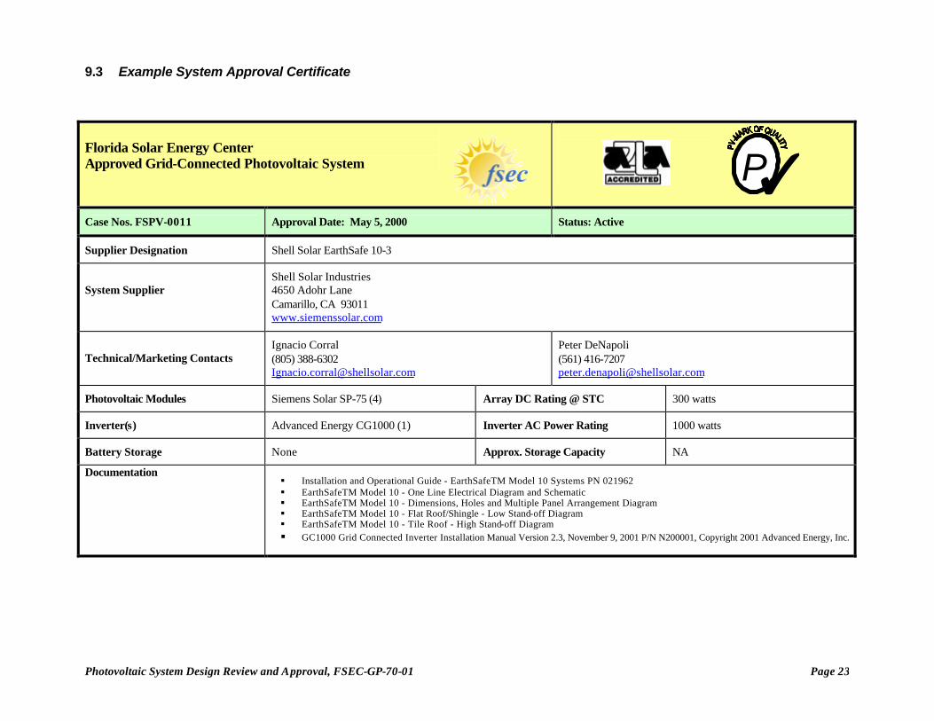
9.3 Example System Approval Certificate
Florida Solar Energy Center Approved Grid-Connected Photovoltaic System
Case Nos. FSPV-0011 Approval Date: May 5, 2000 Status: Active
Supplier Designation Shell Solar EarthSafe 10-3
System Supplier
Shell Solar Industries 4650 Adohr Lane Camarillo, CA 93011 www.siemenssolar.com
Technical/Marketing Contacts Ignacio Corral (805) 388-6302 [email protected]
Peter DeNapoli (561) 416-7207 [email protected]
Photovoltaic Modules Siemens Solar SP-75 (4) Array DC Rating @ STC 300 watts
Inverter(s) Advanced Energy CG1000 (1) Inverter AC Power Rating 1000 watts
Battery Storage None Approx. Storage Capacity NA
Documentation § Installation and Operational Guide - EarthSafeTM Model 10 Systems PN 021962 § EarthSafeTM Model 10 - One Line Electrical Diagram and Schematic § EarthSafeTM Model 10 - Dimensions, Holes and Multiple Panel Arrangement Diagram § EarthSafeTM Model 10 - Flat Roof/Shingle - Low Stand-off Diagram § EarthSafeTM Model 10 - Tile Roof - High Stand-off Diagram § GC1000 Grid Connected Inverter Installation Manual Version 2.3, November 9, 2001 P/N N200001, Copyright 2001 Advanced Energy, Inc.
TP


![Design of Grid-Connected Photovoltaic System · weight of photovoltaic system [7]. The grid[6] -connected photovoltaic systems also need the inverters for power conversion, grid interconnection](https://img.pdfslide.us/doc/110x75/5fba0adb999fbb3bbe303c6e/design-of-grid-connected-photovoltaic-system-weight-of-photovoltaic-system-7.jpg)