Embed Size (px)
Citation preview
GEEnergy Connections
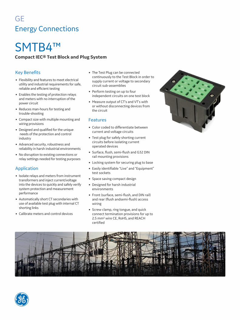
SMTB4™ Compact IEC® Test Block and Plug System
Key Benefits� Flexibility and features to meet electrical
utility and industrial requirements for safe, reliable and efficient testing
� Enables the testing of protection relays and meters with no interruption of the power circuit
� Reduces man-hours for testing and trouble-shooting
� Compact size with multiple mounting and wiring provisions
� Designed and qualified for the unique needs of the protection and control industry
� Advanced security, robustness and reliability in harsh industrial environments
� No disruption to existing connections or relay settings needed for testing purposes
Application� Isolate relays and meters from instrument
transformers and inject current/voltage into the devices to quickly and safely verify system protection and measurement performance
� Automatically short CT secondaries with use of available test plug with internal CT shorting links
� Calibrate meters and control devices
� The Test Plug can be connected continuously to the Test Block in order to supply current or voltage to secondary circuit sub-assemblies
� Perform testing on up to four independent circuits on one test block
� Measure output of CT’s and VT’s with or without disconnecting devices from the circuit
Features� Color coded to differentiate between
current and voltage circuits
� Test plug for safely shorting current circuits before isolating current operated devices
� Surface, flush, semi-flush and G32 DIN rail mounting provisions
� Locking system for securing plug to base
� Easily identifiable “Live” and “Equipment” test sockets
� Space saving compact design
� Designed for harsh industrial environments
� Front (surface, semi-flush, and DIN rail) and rear (flush andsemi-flush) access wiring
� Screw clamp, ring tongue, and quick connect termination provisions for up to 2.5 mm² wire CE, RoHS, and REACH certified

Test Block
Test Block DetailsDimensions (for reference only) are shown below for the four (4) different test block mounting styles available. Part numbers for the different styles are shown on page 7. Flush mount and DIN rail adapter kits are available in kit form.
G32 DIN Rail Mount
Available with screw clamp terminations only
Semi-Flush Mount
Available with ring tongue, quick connect, and screw clamp terminations
Surface Mount
Available with screw clamp terminations only
SMTB4™ Test Block and Plug System
Threaded insert for securing test plug to block to prevent unplugging during testing
GEGridSolutions.com
Terminal numbers:Incoming transformers: 1, 2, 3, 4Equipment: 01, 02, 03, 04
Threaded insert for securing test plug to block to prevent unplugging during testing
Screw clamp terminal location:Available with surface, semi-flush &G32 DIN rail mount only
Flush Mount
Available with ring tongue and quick connect terminations only
Test Block Cover
Order part number SMTB4TBLA separately, see page 7
Test Block Outline
Overall dimensions apply to all test blocks; however, rear provision for ring tongue and quick connect terminations is not provided for surface and DIN rail mounting styles
Ring tongue & quick connect terminal location: Available with flush & semi-flush mount only
Coding pin location6 positions
Color Coded Face:Current = GreenVoltage = Black
Plug directionpositioning feature

Test PlugThe test plug is available with and without test leads. Insulated plugs are available (see part number on page 7) for user to assemble custom test lead lengths and colors as required. Contact pins are included with both options. Pin crimping and installation instructions are shown below. Plugs are color coded for safety purposes and are designed to provide a convenient and safe means of testing current and voltage circuits. The test plugs are equipped with coding pins for installation by user to ensure proper match between block and plug. Operator safety has been the primary concern during the design of the SMTB4 test block system.
SMTB4™ Test Block and Plug System
Test Plug Pin Installation� See pin installation instructions
to the right.
� Pre-wired current and voltage plugs without internal shorting
� links supplied with (8) 2.5mm² x 1.7m insulated leads with 4mm
� diameter insulated double test plugs.
� Pre-wired current plugs with internal shorting links supplied with
� (4) 2.5mm² x 1.7m insulated leads with 4 mm diameter insulated double test plugs.
� Leads marked 1, 2, 3, 4 on pre-wired plugs are red.
� Leads marked 01, 02, 03, 04 on pre-wired plugs are black.
GEGridSolutions.com

Coding Pin Installation1. Locate the one hex shaped coding pin provision in the test block corner close to terminal 4 and insert the coding pin from the bottom of the test block into any one of the six available locations. See step 1.2. Insert the test plug coding pin into the opening left by the test block coding pin. See step 2.3. Install the test plug into the test block. This will align the two mating coding pins. See step 3.4. Remove the test plug from the test block and gently tap the coding pin into the plug to make sure it has been properly seated. See step 4.
Step 4
Step 2
SMTB4™ Test Block and Plug System
GEGridSolutions.com
Step 1
Step 3

SMTB4™ Test Block and Plug System
GEGridSolutions.com
Typical Current Test Block and Plug Applications

Typical Voltage Test Block and Plug Applications
� USERS must ensure that external shorting links are NOT installed on POTENTIAL circuits.
� USERS must ensure that when using test plugs with internally shorted terminals the CTs are wired to the corresponding test block terminals.
SMTB4™ Test Block and Plug System
Caution Statements � To avoid high voltage shock hazard, external CT terminals must
NOT be open circuited. Shorting links MUST be in place BEFORE Test Plug insertion.
� USERS must ensure that external shorting links are installed for CT secondary windings prior to inserting the Test Plug into the Test Block.
GEGridSolutions.com

SMTB4™ Test Block and Plug System
GEGridSolutions.com

Specifications
Voltage
Rated 400 V AC/DCImpulse Withstand 4 kV
Current
Rated 20 A ACShort Circuit 200 A / 1s AC 100 A / 5 s. AC
Temperature Range
IEC 60255-1 Storage & Transit -25 °C to +70 °COperating -25 °C to +55 °C
IP Rating
Front panel IP40 (w/cover) IP20 (w/o cover)
Maximum Working Voltage
IEC 60255-5:2000 400 V AC or DC continuous
Position diagram front view
GEGridSolutions.comGrid-AIS-L4-ITI_Model_SMTB4-1578-2017_05-EN. © Copyright 2017. General Electric Company and Instrument Transformers LLC reserve the right to change specifications of described products at any time without notice and without obligation to notify any person of such changes.
Worldwide Contact CenterWeb: www.GEGridSolutions.com/contactPhone: +44 (0) 1785 250 070USA and Canada: +1 (0) 800 547 8629Europe, Middle East and Africa: +34 (0) 94 485 88 00
Insulation Withstand
IEC 60255-5:2000 4 kV rms for one minute between poles and between poles and ground.
Surge
IEC 61000-4-5
Environmental
IEC 60068-2-1/2IEC 60068-2-78RoHS / REACH
Mechanical
IEC 60255-21-1/2/3 Class II
EMC
Electromagnetically benign; Excluded from Directive 2004/108/EC
Product Safety
CE 2006/95/EC