Embed Size (px)
Citation preview
Greg Bessette and Jason LiberskyComputational Physics Research and Development (9231)
Sandia National Laboratories
Albuquerque NM
8th US National Congress on Computational Mechanics
Austin TX
25 – 27 July 2005
Sandia is a multiprogram laboratory operated by Sandia Corporation, a Lockheed Martin Company,for the United States Department of Energy under contract DE-AC04-94AL85000.
A Coupled Euler-Lagrange Approach for Modeling Penetration and
Blast/Structure Interaction

Zapotec Collaborators
• John Prentice (SCI-TAC LLC)• Paul Yarrington (SNL, 9902)• Courtenay Vaughan (SNL, 9224)• Ray Bell (SNL, 9231)• Sue Goudy (SNL, 9224)• Steve Attaway (SNL, 9134)• Steward Silling (SNL, 9231)• Richard Koteras (SNL, 9142)• Bob Cole (Orion International Technologies)• And others ....

Motivation
• Penetration and blast/structure interaction characterized by:– Transient wave propagation, large material deformations, high
strain rates, multi-body contact, etc.– Materials exhibiting vastly differing strengths and degrees of
deformation
• Many regimes of interest cannot be modeled using traditional methods
• Coupled solution approach can fill the void
Earth Penetration Blast Loading on a Building

Coupled Methods
• Many coupled approaches available for modeling penetration and blast/structure interaction– Engineering models/FE, CEL, FE/SPH, ALE, etc. – One-way vs. loosely-coupled methods
• Present discussion focused on coupled Euler-Lagrange (CEL) approach embedded in the Zapotec code

• Coupled Euler-Lagrange computer code
• Directly couples two production codes– CTH: Eulerian shock physics code– Pronto3D: Explicit, Lagrangian FE code
• Zapotec couples interaction between Lagrangian and Eulerian materials
• Only handles 3D problems
What is Zapotec?

Zapotec Background The Coupled Algorithm in Time
• CTH and Pronto3D are run sequentially, cycle by cycle• Algorithm permits Pronto3D subcycling

The Zapotec Coupling Algorithm
• Coupled treatment conducted in two steps, referred to as material insertion and force application
• Material insertion step updates CTH data
• Force application step updates Pronto3D data

The Zapotec Coupling Algorithm
Material Insertion Step
• Remove pre-existing Lagrangian material from the CTH mesh
• Get updated Lagrangian data• Insert Lagrangian material into CTH
mesh– Compute volume overlaps– Map Lagrangian data – mass,
momentum, sound speed, stress, internal energy
LagrangianMaterial
CTH Mesh
tn
L1
L2
PL,inserted = (VO,L1 PL1 + VO,L2 PL2) / VO
Voverlap = VO = VO,L1 + VO,L2
The Zapotec Coupling Algorithm
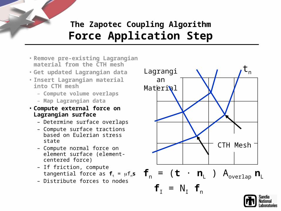
Force Application Step
• Remove pre-existing Lagrangian material from the CTH mesh
• Get updated Lagrangian data• Insert Lagrangian material into CTH
mesh– Compute volume overlaps– Map Lagrangian data
• Compute external force on Lagrangian surface
– Determine surface overlaps– Compute surface tractions based on
Eulerian stress state– Compute normal force on element
surface (element-centered force)– If friction, compute tangential force
as ft = fns– Distribute forces to nodes
LagrangianMaterial
CTH Mesh
tn
fn = (t · nL ) Aoverlap nL
fI = NI fn

Highlight of Zapotec Capabilities
• Supports several Pronto3D element types for material insertion– 8-node hexahedral element– 8-node tetrahedral element– 4-node shell element
• Compatible with CTH-AMR capability
• Can model response of complex, thin-shell structures
• Element death (a.k.a. erosion) accounted for in the force application step
• Parallel implementation

CTH
Parallel ImplementationPronto3D
Master processor
Workers
CTH
Zapotec
Contact
• CTH and Pronto3D have different mesh decompositions
• Data resides on different processors
• Lagrangian data communicated for coupled calculations

Processor Interactions Between CTH and Pronto3D
Processor InteractionsCTH / PRONTO Total• 1 - 7, 8, 9, 10 4• 2 - 6, 7, 8, 9 4• 5 - 5, 7 2• 6 - 1, 2, 3, 4, 5, 6, 7 7• 10 - 0, 1, 2 3
CTH Mesh Decomposition
Pronto3D Mesh Decomposition
Overlapping data owned by different processors Pronto3D data and CTH mesh coordinates communicated to idle processors to load balance work
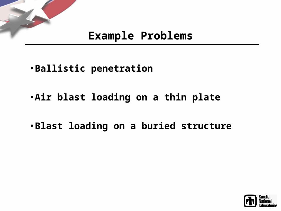
Example Problems
• Ballistic penetration
• Air blast loading on a thin plate
• Blast loading on a buried structure

Ballistic Penetration
• Normal impact of 4340 steel penetrator into 6061-T651 aluminum plate
– Piekutowski, Forrestal, Poorman, and Warren, “Penetration of Aluminum Plates with Ogive-nose Steel Rods at Normal and Oblique Impacts”, Int. J. Impact Engng, Vol. 18, pp. 877-887 (1996)
• Penetrator characteristics– Ogive nose (3CRH), 88.9 mm long, 12.9 mm
diameter– Impact velocities range from 282 to 863 m/s– Pitch/yaw generally less than one degree
• Plate dimensions: 304 x 304 x 26.3 mm
• Drivers for coupled modeling– Disparity in material response– Relatively low impact velocities

Ballistic Penetration
• Penetrator is Lagrangian, plate is Eulerian
• AOA modeled in some instances
• Model friction with a velocity-dependent friction model where friction coefficient is specified as a function of sliding velocity
– No data available for steel-aluminum contact, but data is available for steel-steel contact
• Bowden and Persson, “Deformation, heating, and melting of solids in high-speed friction”, Proc. Royal Society, Vol. 160, pp. 433-458 (1961)
• Friction coefficients range from 5 to 18 percent at sliding velocities of 600 and 20 m/s, respectively
– Zapotec utilizes a piecewise linear fit to the data
• Comparisons with measured residual velocity
(Courtesy: Bowden and Persson)

Ballistic Penetration
• Plate response modeled using EP and Johnson-Cook constitutive models with Mie-Gruneisen EOS
• AOA (combined pitch and yaw) also considered
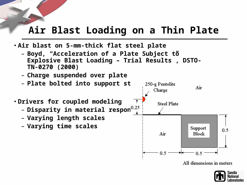
Air Blast Loading on a Thin Plate
• Air blast on 5-mm-thick flat steel plate– Boyd, “Acceleration of a Plate Subject to Explosive Blast
Loading – Trial Results”, DSTO-TN-0270 (2000)– Charge suspended over plate– Plate bolted into support structure
• Drivers for coupled modeling– Disparity in material response– Varying length scales– Varying time scales

Air Blast Loading on a Thin Plate
• Charge and air are Eulerian
• Plate and support are Lagrangian– Plate modeled with 4-node shell elements– Block modeled with 8-node hex elements– Joint modeled as clamped BC
• CTH calculation cutoff after 400 sec
• Pronto3D calculation run to 100 msec
• Run with and without CTH-AMR– Phenomenological-based indicators– Charge: Volume fraction > 0– Shock: Pressure difference histogram– Plate: Vmag > 10 cm/s
• Comparisons for centerline displacements
AirCharge

Air Blast Loading on a Thin Plate
CTH CellSize (cm)
2.0
0.5
Test
8.0 (LOR=4)
Permanent
9
9.8
12.0
12.5
Peak
35
24.2
25.1
25.3
Centerline Displacement (mm)

Air Blast Loading on a Thin Plate

Blast Loading on a Buried Structure• Conventional Weapon Effects Backfill (CONWEB) Test 1
–Hayes, “Backfill Effects on Response of Buried Reinforced Concrete Slabs”, TR-SL-89-19–15.4-lb cased C-4 charge at 5-ft standoff in clay backfill–Test Structure
• Reinforced concrete (RC) slab bolted to reusable reaction structure• Slab thickness: 4.3 inches• Reaction Structure: 15 ft long, 65 inches high, 4 ft deep
– Structure and soil instrumented
• Drivers for coupled modeling–Disparity in material response–Load duration

Blast Loading on a Buried Structure
• Soil and charge are Eulerian–Charge: JWL Library EOS for C-4–Steel case: Elastic-plastic –Soil: P-alpha EOS with Geologic (GEO)
strength model
• Structure is Lagrangian–Reinforcement and bolted connections
explicitly modeled–Concrete: K&C model–Reinforcement: Rebar model–Displacement-based death criterion used
to model breach (d/CS > 0.3)
• Comparisons–Free-field soil stress and velocity–Structure velocities–Interface pressures
CTH MeshBoundaries
Plane ofSymmetry
Free Surface
Plane ofSymmetry

Blast Loading on a Buried Structure
AHS-0: Center of RC Slab
AHS-10: Base of Reaction Structure
RC Slab: Thickness: 4.3 inches Strength (fc’): 6095 psi Reinforcement: 1.0 % Backfill: Clay

Blast Loading on a Buried Structure

Concluding Remarks
• CEL approach well suited for modeling penetration and blast/structure interaction
• Open issues for coupling algorithm– Consistent material modeling for insertion step
– Overfilled cells
– Cost of volume/area overlap calculations