Embed Size (px)
Citation preview

L N 3N1 1 2 6a654
!
231
0 4bar
Internal Terminal Connection Block
Greenstar Danesmoor Kitchen System ErP2H-R-E
All electrical work should be carried out by a registered engineer. Wiring must comply with the latest IET wiring regulations. Isolate the mains electricity supply before starting any work and observe all relevant safety precautions. Refer to all relevant product installation manuals for safety and installation instructions. Whilst it is always our intention to fully assist, it is essential to recognise that all information given by the company is provided in good faith and based upon the information available. Connection labels may not match those of the products installed on site. We recommend that advice should always be checked with your installer, electrician or the manufacturer of the product in question. Consequently, the company cannot be held responsible for any liability relating to the use or repetition of such information or part thereof. In addition, whilst making every reasonable effort to monitor the performance and quality of our supply, installation and service network, we do not accept responsibility for the workmanship or operation of any third party company.
WG D-KS-2H-R-E a (2016/12)
2 Heating Zones
L LIVE N NEUTRAL EARTHE
The following labels and those like them are used to denote generic connections (such as the live supply to components) in order to simplify the diagram:
Programmer
~ ~
Room Thermostat 1
CH1 D CH2 D
HeatingZone Valve 2
HeatingZone Valve 1
230V MainsVoltage
Double PoleFused Spur
1 2 3 4 5 7 8 9 106
C D
Legend:LNLRECSDMCH DHW D
= Live= Neutral= Live Return= Earth= Common= Satisfied= Demand= Motor= Central Heating Demand= Hot Water Demand
Room Thermostat 2
C D
Wiring Centre
7 8 109Internal Programmer Connector
Link Connector Fitted
EL N
N
L
LN
E
N E
N N
EN
L EN
L
!
231
0 4bar
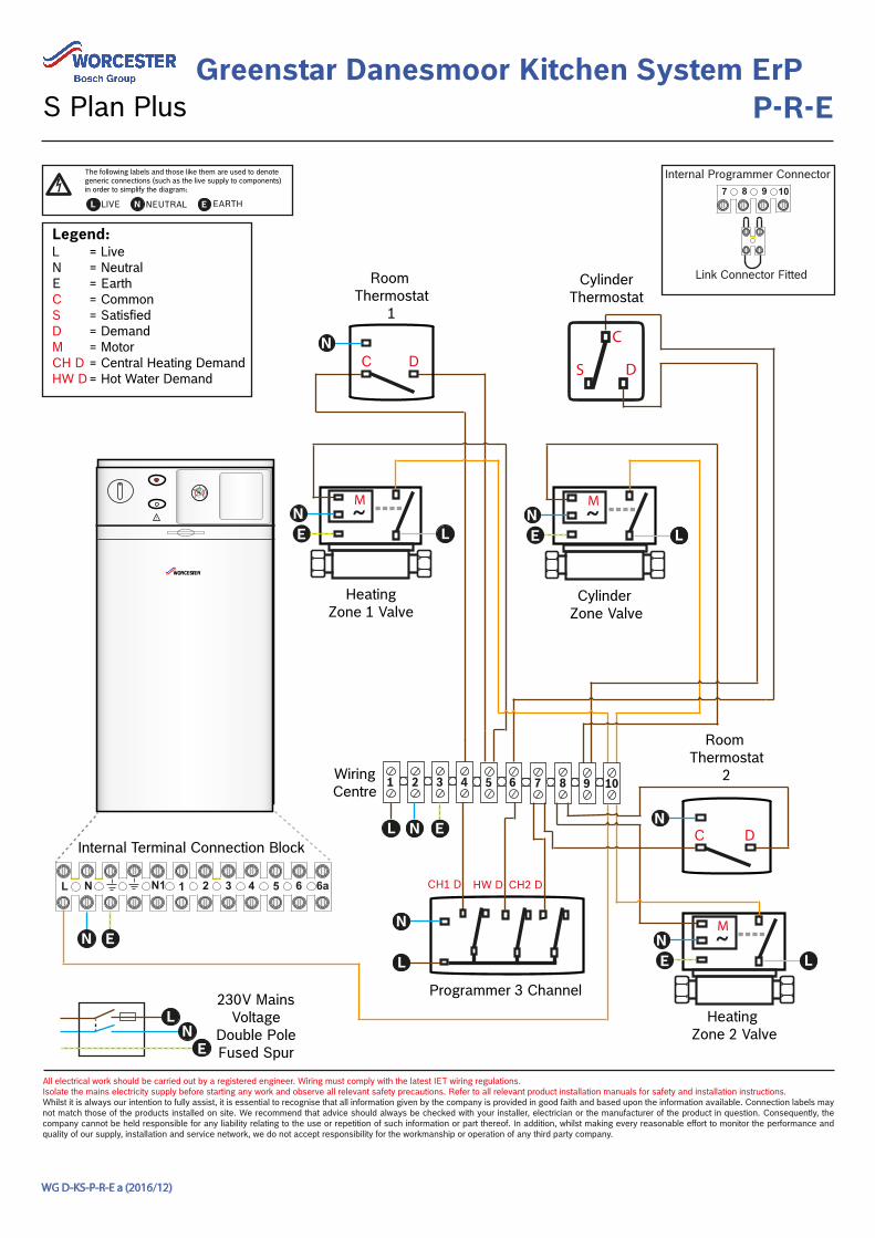
Room Thermostat
1
CylinderThermostat
Programmer 3 Channel
CH1 D HW D
C D
~
HeatingZone 1 Valve
~
Cylinder Zone Valve
Legend:LNECSDMCH DHW D
= Live = Neutral = Earth= Common= Satisfied= Demand= Motor= Central Heating Demand= Hot Water Demand
L N 3N1 1 2 6a654
Internal Terminal Connection Block
230V MainsVoltage
Double PoleFused Spur
7 8 109Internal Programmer Connector
Link Connector Fitted
C
S D
CH2 D
Room Thermostat
2
~
Heating Zone 2 Valve
1 2 3 4 5 7 8 9 106Wiring Centre
EN
L EN
L
EN
L
N
L
EL N
N
N
LN
E
N E
C D
Greenstar Danesmoor Kitchen System ErPP-R-E
All electrical work should be carried out by a registered engineer. Wiring must comply with the latest IET wiring regulations. Isolate the mains electricity supply before starting any work and observe all relevant safety precautions. Refer to all relevant product installation manuals for safety and installation instructions. Whilst it is always our intention to fully assist, it is essential to recognise that all information given by the company is provided in good faith and based upon the information available. Connection labels may not match those of the products installed on site. We recommend that advice should always be checked with your installer, electrician or the manufacturer of the product in question. Consequently, the company cannot be held responsible for any liability relating to the use or repetition of such information or part thereof. In addition, whilst making every reasonable effort to monitor the performance and quality of our supply, installation and service network, we do not accept responsibility for the workmanship or operation of any third party company.
WG D-KS-P-R-E a (2016/12)
S Plan Plus
L LIVE N NEUTRAL EARTHE
The following labels and those like them are used to denote generic connections (such as the live supply to components) in order to simplify the diagram:
!
231
0 4bar
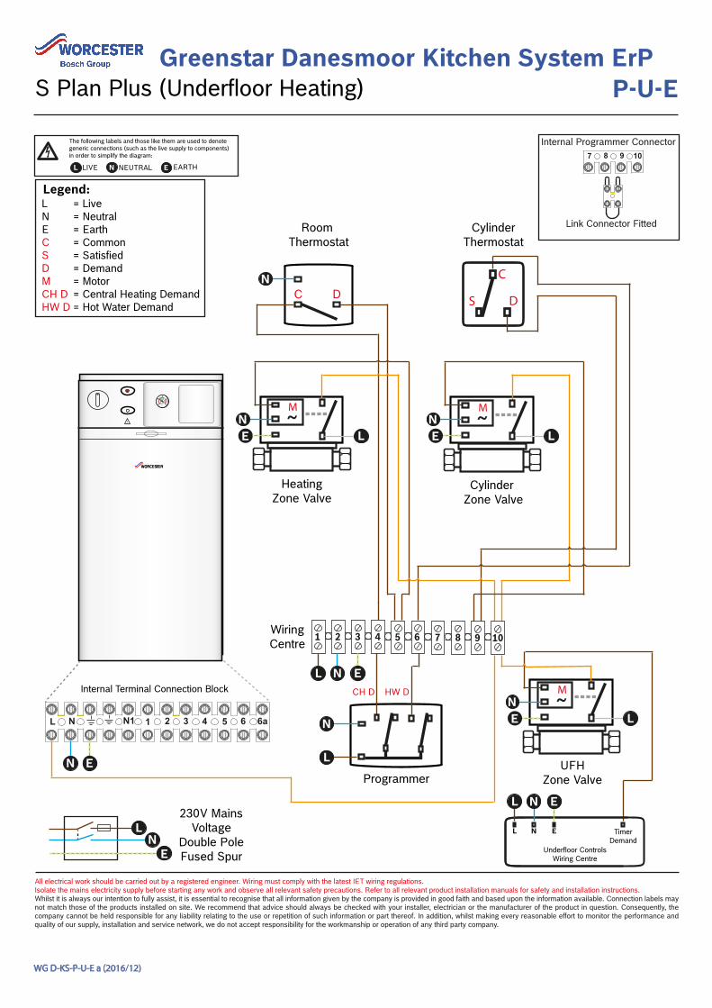
Greenstar Danesmoor Kitchen System ErPP-U-E
All electrical work should be carried out by a registered engineer. Wiring must comply with the latest IET wiring regulations. Isolate the mains electricity supply before starting any work and observe all relevant safety precautions. Refer to all relevant product installation manuals for safety and installation instructions. Whilst it is always our intention to fully assist, it is essential to recognise that all information given by the company is provided in good faith and based upon the information available. Connection labels may not match those of the products installed on site. We recommend that advice should always be checked with your installer, electrician or the manufacturer of the product in question. Consequently, the company cannot be held responsible for any liability relating to the use or repetition of such information or part thereof. In addition, whilst making every reasonable effort to monitor the performance and quality of our supply, installation and service network, we do not accept responsibility for the workmanship or operation of any third party company.
WG D-KS-P-U-E a (2016/12)
S Plan Plus (Underfloor Heating)
L LIVE N NEUTRAL EARTHE
The following labels and those like them are used to denote generic connections (such as the live supply to components) in order to simplify the diagram:
~
Room Thermostat
CylinderThermostat
Programmer
CH D HW D
Cylinder Zone Valve
C D
~
HeatingZone Valve
Legend:LNECSDMCH DHW D
= Live = Neutral = Earth= Common= Satisfied= Demand= Motor= Central Heating Demand= Hot Water Demand
L N 3N1 1 2 6a654
Internal Terminal Connection Block
230V MainsVoltage
Double PoleFused Spur
7 8 109Internal Programmer Connector
Link Connector Fitted
1 2 3 4 5 7 8 9 106
C
S D
EN
L
Timer Demand
~
UFHZone Valve
Wiring Centre
N
EN
L
EL N
EN
L
LN
E
N E
Underfloor ControlsWiring Centre
L N E
EL N
N
L

!
231
0 4bar
N
~ ~
Room Thermostat
C
S D
CylinderThermostat
EN
L
Programmer
CH D HW D
Cylinder Zone Valve
HeatingZone Valve
C D
Legend:LNECSDMCH DHW D
= Live = Neutral = Earth= Common= Satisfied= Demand= Motor= Central Heating Demand= Hot Water Demand
L N 3N1 1 2 6a654
Internal Terminal Connection Block
230V MainsVoltage
Double PoleFused Spur
7 8 109Internal Programmer Connector
Link Connector Fitted
1 2 3 4 5 7 8 9 106Wiring Centre
EN
L
N E
N
L
EL N
LN
E
Greenstar Danesmoor Kitchen System ErPS-R-E
All electrical work should be carried out by a registered engineer. Wiring must comply with the latest IET wiring regulations. Isolate the mains electricity supply before starting any work and observe all relevant safety precautions. Refer to all relevant product installation manuals for safety and installation instructions. Whilst it is always our intention to fully assist, it is essential to recognise that all information given by the company is provided in good faith and based upon the information available. Connection labels may not match those of the products installed on site. We recommend that advice should always be checked with your installer, electrician or the manufacturer of the product in question. Consequently, the company cannot be held responsible for any liability relating to the use or repetition of such information or part thereof. In addition, whilst making every reasonable effort to monitor the performance and quality of our supply, installation and service network, we do not accept responsibility for the workmanship or operation of any third party company.
WG D-KS-S-R-E a (2016/12)
S Plan
L LIVE N NEUTRAL EARTHE
The following labels and those like them are used to denote generic connections (such as the live supply to components) in order to simplify the diagram:

!
231
0 4bar
~ ~
Room Thermostat
C
S D
CylinderThermostat
Programmer
Wiring Centre
CH D HW D
Cylinder Zone Valve
HeatingZone Valve
C D
Legend:LNLRECSDMCH DHW D
= Live = Neutral = Live Return= Earth= Common= Satisfied= Demand= Motor= Central Heating Demand= Hot Water Demand
Internal Terminal Connection Block
230V MainsVoltage
Double PoleFused Spur
7 8 109Internal Programmer Connector
Link Connector Fitted
1 2 3 4 5 7 8 9 106
L N 3N1 1 2 6a654
EN
L EN
L
EL N
N
L
LN
E
N E
Greenstar Danesmoor Kitchen System ErPS-R-E-FZ
All electrical work should be carried out by a registered engineer. Wiring must comply with the latest IET wiring regulations. Isolate the mains electricity supply before starting any work and observe all relevant safety precautions. Refer to all relevant product installation manuals for safety and installation instructions. Whilst it is always our intention to fully assist, it is essential to recognise that all information given by the company is provided in good faith and based upon the information available. Connection labels may not match those of the products installed on site. We recommend that advice should always be checked with your installer, electrician or the manufacturer of the product in question. Consequently, the company cannot be held responsible for any liability relating to the use or repetition of such information or part thereof. In addition, whilst making every reasonable effort to monitor the performance and quality of our supply, installation and service network, we do not accept responsibility for the workmanship or operation of any third party company.
WG D-KS-S-R-E-FZ a (2016/12)
Frost Protection (with Zoned Pipework)
L LIVE N NEUTRAL EARTHE
The following labels and those like them are used to denote generic connections (such as the live supply to components) in order to simplify the diagram:
L
ExternalFrost Thermostat
C D
ReturnPipe Thermostat
CD
N

!
231
0 4bar
Room Thermostat
C DC
S D
CylinderThermostat
230V MainsVoltage
Double PoleFused Spur
Legend:LNECSDMCH DHW DHW O
= Live = Neutral = Earth= Common= Satisfied= Demand= Motor= Central Heating Demand= Hot Water Demand= Hot Water Off
Mid PositionValve
Orange = DGrey = SWhite = CH D
(Remove link 1 to 3)
1 2 3 4 5 7 8 9 106
HW DCH D
HW O
L N 3N1 1 2 6a654
WiringCentre
L
7 8 109
Hot Water Central Heating
Advance Set ?
YesSelect
Advance
Select
Off
OnOnceTimed
Off
OnOnceTimed
Optional Worcester Programmer:Refer to Installation instructions for detailed guidance.
N
EL N
LN
E
EN
Greenstar Danesmoor Kitchen System ErPY-R-I
All electrical work should be carried out by a registered engineer. Wiring must comply with the latest IET wiring regulations. Isolate the mains electricity supply before starting any work and observe all relevant safety precautions. Refer to all relevant product installation manuals for safety and installation instructions. Whilst it is always our intention to fully assist, it is essential to recognise that all information given by the company is provided in good faith and based upon the information available. Connection labels may not match those of the products installed on site. We recommend that advice should always be checked with your installer, electrician or the manufacturer of the product in question. Consequently, the company cannot be held responsible for any liability relating to the use or repetition of such information or part thereof. In addition, whilst making every reasonable effort to monitor the performance and quality of our supply, installation and service network, we do not accept responsibility for the workmanship or operation of any third party company.
WG D-KS-Y-R-I a (2016/12)
Y Plan (Mid Position Valve)
L LIVE N NEUTRAL EARTHE
The following labels and those like them are used to denote generic connections (such as the live supply to components) in order to simplify the diagram:
Internal Terminal Connection Block