Embed Size (px)
Citation preview
e-ISSN: 2582-5208 International Research Journal of Modernization in Engineering Technology and Science
( Peer-Reviewed, Open Access, Fully Refereed International Journal )
Volume:03/Issue:09/September-2021 Impact Factor- 6.752 www.irjmets.com
www.irjmets.com @International Research Journal of Modernization in Engineering, Technology and Science
[1578]
GREENHOUSE ENVIRONMENT CONTROLLING ROBOT
Vinaya Pandurang Chandanshiv*1, Prof. S.K. Kapde*2
*1P.G. Student, Dept Of Electronics And Telecommunication Engineering, Deogiri College Of
Engineering And Management, Aurangabad, Maharashtra, India.
*2Assistant Professor, Dept Of Electronics And Telecommunication Engineering, Deogiri College Of
Engineering And Management, Aurangabad, Maharashtra, India.
ABSTRACT
In this project an automated greenhouse robot was built with the purpose of controlling the greenhouse
environment Parameters such as tempreture and humidity. The microcontroller used to create the automated
greenhouse robot was an AT89s51. This project utilizes three different sensors, a humidity sensor, a Light
sensor and a temperature sensor. The 2sensors are controlling the two Relays which are a fan (for cooling) and
a bulb (for heating). The fan is used to change the temperature and the bulb is used to heat the plants. The
humidity control system and the temperature control system were tested both separately and together. The
result showed that the tempreture and humidity could be maintained in the desired range.
Keywords: Light Sensor, Temperature Sensor, Humidity Sensor, Monitoring, Controlling, PIC Microcontroller.
I. INTRODUCTION
Greenhouses plays a major role in today's agriculture since farmers can grow plants under controlled climatic
conditions and can optimize production. The greenhouses are usually built-in areas where the climatic
condition for the growth of plants are not optimal so requires some artificial setups to bring about productivity.
Automating process of a greenhouse requires monitoring and controlling of the climatic parameters. With the
increasing population and the need of the human being for more space has led to reduction of forests, farm etc.
This in turn results in global heating which has adverse effects on our life. The importance of plants, trees is
thus increasing with time. This led us to do a project on the greenhouse, a place we can grow plants of different
varieties under one roof. Using machine tools and robotics new harvesting systems are starting to emerge for
high value crops. Here in this project, we are monitoring and controlling the different parameters through
microcontroller. The applications of instrumental robotics are spreading everyday to cover further domains as
the opportunity of replacing humans’ operators provides effective solutions with return on investment. This is
especially important when duties, that need to be performed, are potentially harmful for the society or the
health of the worker, or when more conservative issues are granted by robotics. Heavy chemicals or drug
dispenser, manure or fertilizers spreaders, etc. are activities more and more concerned by the deployment of
unmanned options greenhouses are translucent glass or plastic constructions for hastening the growth of the
plants. The distribution of plants inside greenhouses usually consists of an alteration of double rows of plants
and narrow corridors for human operation and walkway. This kind of agricultural technique is massively used
for intensive production of horticultural products in region with adverse natural climatic conditions, since it
allows a more effective use of water and daylight.
1.1 Project specification
This project deals with the monitoring and controlling of the greenhouse parameters such as humidity,
temperature and light. Here we have designed a microcontroller-based prototype model where we are
controlling the above-mentioned parameters through the microcontroller. Here we are monitoring parameters
like temperature, light and humidity. For measurement of these parameters, we need sensors which respond to
the changes in the parameters appropriately. Hence, we have used LM35 as temperature sensors, SY-HS-220 as
the humidity sensor and LDR as the light sensor. As the signals measured are of very low value therefore their
amplification is very necessary. Hence LM324 has been used as a non-inverting amplifier. As LM324 contains 4
op-amps per IC hence it has been used. For the purpose of analog to digital conversion we have used ADC0808.
We are using it as 3:1 multiplexer. IC 555 has been used as a timer IC to provide a clock signal to the ADC0808.
It is used as astable multivibrator with 50% duty cycle for 220 KHz frequency. The heart of the project i.e., the
microcontroller is AT89S51. It is used because of its larger memory. The display is done through 16×2-line LCD.

e-ISSN: 2582-5208 International Research Journal of Modernization in Engineering Technology and Science
( Peer-Reviewed, Open Access, Fully Refereed International Journal )
Volume:03/Issue:09/September-2021 Impact Factor- 6.752 www.irjmets.com
www.irjmets.com @International Research Journal of Modernization in Engineering, Technology and Science
[1579]
We can also use 4 lines LCD. MAX232 has been used for the interfacing purpose. With the help of this IC, we can
display the data on the computer also. For storing the data for the future use we used EEPROM IC 24C16. The
power module consists of IC7805 for 5V supply and IC7812 for 12V supply.
1.2 Inputs defined in project & their purpose
The input signal in our project is generated through the sensors which are used for sensing the light,
temperature and humidity. The sensors used are:
1. LDR
2. LM35
3. SY-HS-220
1. LDR: The LDR is used for the purpose of light detection. It is a light dependent resistor. The LDR is the
simplest light detector.
2. LM35: The LM35 series are precision integrated-circuit temperature sensors, whose output voltage is
linearly proportional to the Celsius (Centigrade) temperature. The LM35 thus has an advantage over linear
temperature sensors calibrated in ºKelvin, as the user is not required to subtract a large constant voltage
from its output to obtain convenient Centigrade scaling.
3. SY-HS-220: Humidity transmitter provides a high accuracy of 4 to 20mA humidity measurement Accuracies
of 2% RH is available.
1.3 Outputs defined in project & their purpose
The outputs used in the project are
1. Fan
2. Exhaust
3. Heater
1. Fan: The fan is used at the time of increase in the humidity. The fans are used to bring down the moisture
content in the air and thus bring it back within the required range which is set previously.
2. Exhaust: The exhaust fans are used to bring back the temperature within the required level i.e. the higher
range and the lower range which is set previously using the keypad.
3. Heaters: The heaters are used to increase the temperature if the temperature falls below the required
the heater gets switched off when the temperature comes back within the range.
II. BLOCK DIAGRAM
The block diagram consists of six main parts. These are:
1. The sensors
2. ADC
3. Keypad
4. EEPROM
5. Microcontroller
6. The controllers and display
There are 3 sensors blocks i.e., the temperature sensor and amplifier block, the light sensor and amplifier block
and the humidity sensor and amplifier block. The function of this block is to sense the changes in the light,
temperature and humidity respectively and give the output, which is then amplified by the amplifier. The
sensor block basically consists of the sensors and the op-amps. The amplified output is then given to the ADC
for analog to digital conversion. The ADC also provides the control signals to the microcontroller. There is a
keypad which is used to set the temperature ranges, light and humidity, so that the output values can be
compared with these reference values. It also serves the purpose of displaying the various options. The ADC
and the keypad are interfaced with the microcontroller. The microcontroller controls all the output action. The
input from the ADC is used to provide display to the LCD. The microcontroller also provides the data to the
EEPROM where the readings are stored after every certain specified time. This stored data can be checked by
the user, whenever required. The output from the microcontroller is then given to the controller blocks i.e., the
e-ISSN: 2582-5208 International Research Journal of Modernization in Engineering Technology and Science
( Peer-Reviewed, Open Access, Fully Refereed International Journal )
Volume:03/Issue:09/September-2021 Impact Factor- 6.752 www.irjmets.com
www.irjmets.com @International Research Journal of Modernization in Engineering, Technology and Science
[1580]
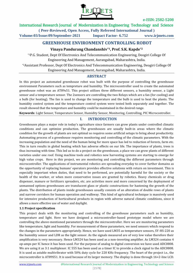
temperature controller, the humidity controller and the motor. The output from the microcontroller is also
given to the PC interface block, which allows data which is being displayed on the LCD to be displayed on the
computer for further calculations, manipulations.
Block diagram
Temperature sensor and amplifier: Temperature sensor is the sensor that measures the amount of heat that
it observes. There are contact and non-contact type of temperature sensors.
Light sensor: Light sensor is the sensor that measures the amount of the light that it sees. Light sensors are
devices convert light energy or affect some electrical parameters. The output of the LDR light sensor is in the
form of resistance.
Humidity sensor: Humidity sensor is the sensor that measures the percentage of moisture content i.e., the
humidity in the air.
ANALOG TO DIGITAL CONVERTER (ADC): -ADC is used as a signal conditioner, which is given as an input to
the micro controller. Most of the information carrying signals such as voltage, current, temperature, pressure
and time are available in analog form.
Block diagram of Power Supply Module
MICRO-CONTROLLER (8051): It is the major part of the system. It maintains the temperature, humidity and
light intensity to the desired value. The 8051 has one serial port that receives and transmits data. Transmission
and reception can take place simultaneously.
Temperature
Sensor &
Amplifier
ADC
Micro-
controller
LCD Display
Relay 1
Motor
Driver
Humidity
Sensor
Relay 2
Buzzer
Light Sensor
Moto
r
1
Motor 2
Filter
Capacitor
Transformer Rectifier
(Bridge)
Voltage
Regulator
5VDC
e-ISSN: 2582-5208 International Research Journal of Modernization in Engineering Technology and Science
( Peer-Reviewed, Open Access, Fully Refereed International Journal )
Volume:03/Issue:09/September-2021 Impact Factor- 6.752 www.irjmets.com
www.irjmets.com @International Research Journal of Modernization in Engineering, Technology and Science
[1581]
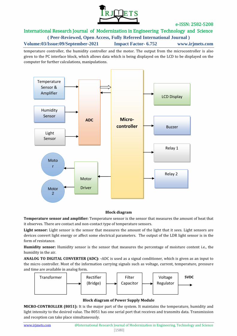
Photograph of an 89s51 microcontroller
LCD DISPLAY: It is used to display the current values of the measuring quantities. It can be used to display the
various options and all the readings that have been stored in the EEPROM. LCD or 7 segment LED display can be
used. Here the LCD used is the 16×2-line LCD.
Photograph of A typical 16 by 2 alphanumeric LCD display
Relay: Relay is used to control the on/off operation of device. Relays are driven by the transistors. We are using
single pole double throw (SPDT) relay.
Temperature Controller: The error between the reference and present value is given to the temperature
controller, which responds correspondingly to the error and gives the feedback to the sensors.
Humidity Controller: The error between the reference and present value is given to the humidity controller,
which responds correspondingly to the error and gives the feedback to the sensors.
DC Motor: A DC motor is a mechanically commutated electric motor powered from direct current (DC). In DC
motor, operation is based on simple electromagnetism.
III. CIRCUIT DIAGRAM
3.1 Circuit Design Procedure
The circuit designing has been divided into three parts. The first part comprises of the op-amps and sensors,
the second part comprises of the processing and displaying part i.e., the microcontroller, ADC, and the LCD. The
third part comprise of the output i.e., the relays through which the controlling action is taken. The first board
consists of one operational amplifier and three sensors. The operational amplifier used is LM358. It is a 8 pin IC
and which consists of 2 op-amps. The op-amp is used as an amplifier. The sensors used for measurement of
temperature, light and humidity are LDR, LM35, SY-HS-220(R).
LDR is the simplest type of light sensor. It is most sensitive to visible light in red. There other sensors also
available like infrared reflectance sensor, infrared slotted optical switch, modulated infrared light detector etc.
But as the name suggests they are sensitive to both visible and infrared light. Our requirement is limited till
visible light only hence LDR is used. Also, LDR is cost effective and readily available in the market.
LM35 is the temperature sensor. This is the simplest type of temperature sensor. We are using the plastic
package LM35DP. The operating temperature range is from -55 to 150ºC. The humidity sensor used is SY-HS-
220. These are available in three types, outside air, duct and room humidity sensor. Since our requirement is of
room humidity hence, we have used SY-HS-220(R). The operating temperature range is from 0 to 70ºC. Also,
the output range is from 4-20 mA. The sensor is readily available in the market. The only drawback is that it is
quite costly.
There are 3 pots used of 10k each, 3 resistors of 2.2k each and 6 resistors of 1k each. The resistors are used for
the gain purpose. The 1k resistor which is connected through pin no. 6 and 13 to the ground act as
compensating resistors. The 20k pot is adjusted to give a voltage of 5V at 60º. From here on the temperature is
e-ISSN: 2582-5208 International Research Journal of Modernization in Engineering Technology and Science
( Peer-Reviewed, Open Access, Fully Refereed International Journal )
Volume:03/Issue:09/September-2021 Impact Factor- 6.752 www.irjmets.com
www.irjmets.com @International Research Journal of Modernization in Engineering, Technology and Science
[1582]
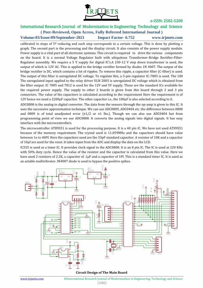
calibrated in steps of 5º reducing and each step corresponds to a certain voltage. This is done by plotting a
graph. The second part is the processing and the display circuit. It also consists of the power supply module.
Power supply is a vital part of all electronic systems. This circuit is required to drive the various components
on the board. It is a normal Voltage Regulator built with ubiquitous Transformer-Bridge Rectifier-Filter-
Regulator assembly. We require a 5 V supply for digital IC’s.A 230-12 V step down transformer is used, the
output of which is 12V AC. This is applied to the bridge rectifier formed by diodes 1N 4007. The output of the
bridge rectifier is DC, which contains a lot of ripples. To remove this ripple, a capacitor filter (C-filter) is used.
The output of this filter is unregulated DC voltage. To regulate this, a 3-pin regulator IC-7805 is used. The 100
The unregulated input applied to the relay driver ULN 2003 is unregulated DC voltage which is obtained from
the filter output. IC 7805 and 7812 is used for the 12V and 5V supply. These are the standard ICs available for
the required power supply. The supply to other 2 boards is given from this board through 2 and 3 pin
connectors. The value of the capacitors is calculated according to the requirement Here the requirement is of
12V hence we need a 2200µF capacitor. The other capacitor i.e., the 100µF is also selected according to it.
ADC0808 is the analog to digital converter. The data from the sensors through the op-amp is given to this IC. It
uses the successive approximation technique. We can use ADC0809, ADC0404 etc. the difference between 0808
and 0809 is of total unadjusted error (±1/2 or ±1 lbs.). Though we can also use ADC0404 but from
programming point of view we use ADC0808. It converts the analog signals into digital signals. It has easy
interface with the microcontrollers.
The microcontroller AT89S51 is used for the processing purpose. It is a 40 pin IC. We have not used AT89S51
because of the memory requirement. The crystal used is 11.059MHz and the capacitors should have value
between 1o to 40Pf. Here the capacitors used are the 33pF standard capacitor. A resistor of 10K and a capacitor
of 10µf are used for the reset. It takes input from the ADC and display the data on the LCD.
IC555 is used as a timer IC. It provides clock signal to the ADC0808. It is an 8 pin IC. The IC is used at 220 KHz
with 50% duty cycle. Hence the value of the resistor and the capacitor is calculated from this value. Here we
have used 2 resistors of 2.2K, a capacitor of .1µF and a capacitor of 1Pf. This is a standard timer IC. It is used as
an astable multivibrator. IN4007 diode is used to bypass the positive spikes.
Circuit Design of The Main Board
e-ISSN: 2582-5208 International Research Journal of Modernization in Engineering Technology and Science
( Peer-Reviewed, Open Access, Fully Refereed International Journal )
Volume:03/Issue:09/September-2021 Impact Factor- 6.752 www.irjmets.com
www.irjmets.com @International Research Journal of Modernization in Engineering, Technology and Science
[1583]
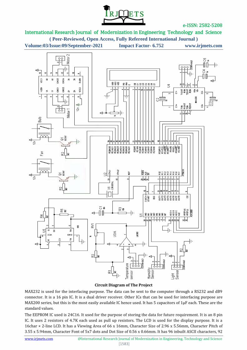
Circuit Diagram of The Project
MAX232 is used for the interfacing purpose. The data can be sent to the computer through a RS232 and dB9
connector. It is a 16 pin IC. It is a dual driver receiver. Other ICs that can be used for interfacing purpose are
MAX200 series, but this is the most easily available IC hence used. It has 5 capacitors of 1µF each. These are the
standard values.
The EEPROM IC used is 24C16. It used for the purpose of storing the data for future requirement. It is an 8 pin
IC. It uses 2 resistors of 4.7K each used as pull up resistors. The LCD is used for the display purpose. It is a
16char × 2-line LCD. It has a Viewing Area of 66 x 16mm, Character Size of 2.96 x 5.56mm, Character Pitch of
3.55 x 5.94mm, Character Font of 5x7 dots and Dot Size of 0.56 x 0.66mm. It has 96 inbuilt ASCII characters, 92
e-ISSN: 2582-5208 International Research Journal of Modernization in Engineering Technology and Science
( Peer-Reviewed, Open Access, Fully Refereed International Journal )
Volume:03/Issue:09/September-2021 Impact Factor- 6.752 www.irjmets.com
www.irjmets.com @International Research Journal of Modernization in Engineering, Technology and Science
[1584]
special characters and 8 custom characters. We can also use 16char × 4-line LCD, but since our requirement is
of 2 lines only hence, we have used this LCD. Here an array of resistor is used with 8 resistors of 4.7K each used
as pull up resistors. These are standard values of the pull-up resistor. A pot of 4.7K is also used for contrast
adjustment. We can also use any other value pot. Power supply is a vital part of all electronic systems. This
circuit is required to drive the various components on the board. It is a normal Voltage Regulator built with
ubiquitous Transformer-Bridge Rectifier-Filter-Regulator assembly. We require a 5 V supply for digital IC’s. A
230-12 V step down transformer is used, the output of which is 12V AC. This is applied to the bridge rectifier
formed by diodes 1N 4007. The output of the bridge rectifier is DC, which contains a lot of ripples. To remove
this ripple, a capacitor filter (C-filter) is used. The output of this filter is unregulated DC voltage. To regulate
this, a 3-pin regulator IC-7805 is used. The 100 The unregulated input applied to the relay driver ULN 2003 is
unregulated DC voltage which is obtained from the filter output.
IC 7805 and 7812 is used for the 12V and 5V supply. These are the standard ICs available for the required
power supply. The supply to other 2 boards is given from this board through 2 and 3 pin connectors. The value
of the capacitors is calculated according to the requirement Here the requirement is of 12V hence we need a
2200µF capacitor. The other capacitor i.e., the 100µF is also selected according to it. ADC0808 is the analog to
digital converter. The data from the sensors through the op-amp is given to this IC. It uses the successive
approximation technique. We can use ADC0809, ADC0404 etc. the difference between 0808 and 0809 is of total
unadjusted error (±1/2 or ±1 lbs.). Though we can also use ADC0404 but from programming point of view we
use ADC0808. It converts the analog signals into digital signals. It has easy interface with the microcontrollers.
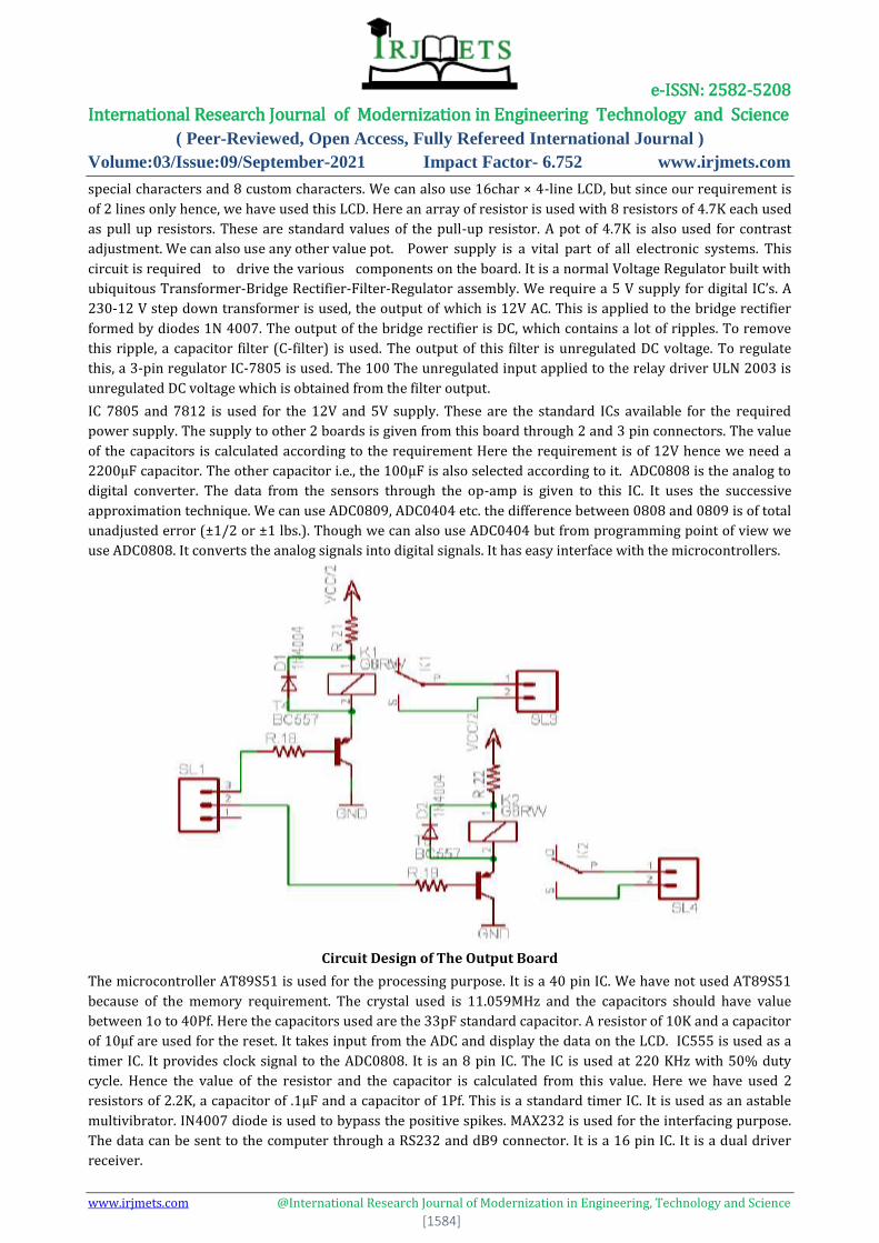
Circuit Design of The Output Board
The microcontroller AT89S51 is used for the processing purpose. It is a 40 pin IC. We have not used AT89S51
because of the memory requirement. The crystal used is 11.059MHz and the capacitors should have value
between 1o to 40Pf. Here the capacitors used are the 33pF standard capacitor. A resistor of 10K and a capacitor
of 10µf are used for the reset. It takes input from the ADC and display the data on the LCD. IC555 is used as a
timer IC. It provides clock signal to the ADC0808. It is an 8 pin IC. The IC is used at 220 KHz with 50% duty
cycle. Hence the value of the resistor and the capacitor is calculated from this value. Here we have used 2
resistors of 2.2K, a capacitor of .1µF and a capacitor of 1Pf. This is a standard timer IC. It is used as an astable
multivibrator. IN4007 diode is used to bypass the positive spikes. MAX232 is used for the interfacing purpose.
The data can be sent to the computer through a RS232 and dB9 connector. It is a 16 pin IC. It is a dual driver
receiver.
e-ISSN: 2582-5208 International Research Journal of Modernization in Engineering Technology and Science
( Peer-Reviewed, Open Access, Fully Refereed International Journal )
Volume:03/Issue:09/September-2021 Impact Factor- 6.752 www.irjmets.com
www.irjmets.com @International Research Journal of Modernization in Engineering, Technology and Science
[1585]
IV. EXPLAINATION OF CIRCUIT DIAGRAM
The AT89S51 is a low-power, high-performance CMOS 8-bit microcontroller with 8K bytes of in-system
programmable Flash memory. The device is manufactured using Atmel’s high-density nonvolatile memory
technology and is compatible with the industry- standard 80C51 instruction set and pin-out. The on-chip Flash
allows the program memory to be reprogrammed in-system or by a conventional nonvolatile memory
programmer. By combining a versatile 8-bit CPU with in-system programmable Flash on a monolithic chip, the
Atmel AT89S51 is a powerful microcontroller which provides a highly-flexible and cost-effective solution to
many embedded control applications.
The AT89S51 provides the following standard features: 8K bytes of Flash, 256 bytes of RAM, 32 I/O lines,
Watchdog timer, two data pointers, three 16-bit timer/counters, a six-vector two-level interrupt architecture, a
full duplex serial port, on-chip oscillator, and clock circuitry. In addition, the AT89S51 is designed with static
logic for operation down to zero frequency and supports two software selectable power saving modes. The Idle
Mode stops the CPU while allowing the RAM, timer/counters, serial port, and interrupt system to continue
functioning. The Power-down mode saves the RAM contents but freezes the oscillator, disabling all other chip
functions until the next interrupt or hardware reset.
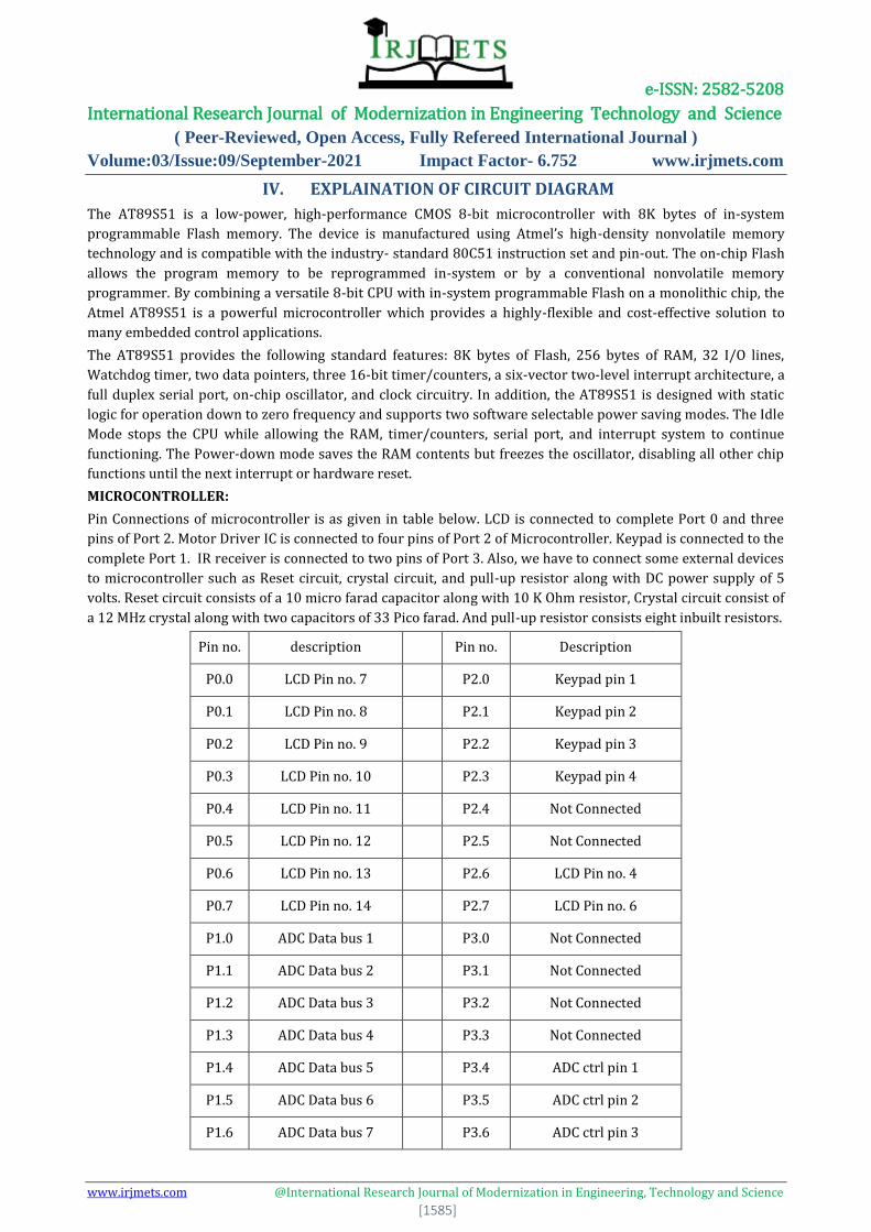
MICROCONTROLLER:
Pin Connections of microcontroller is as given in table below. LCD is connected to complete Port 0 and three
pins of Port 2. Motor Driver IC is connected to four pins of Port 2 of Microcontroller. Keypad is connected to the
complete Port 1. IR receiver is connected to two pins of Port 3. Also, we have to connect some external devices
to microcontroller such as Reset circuit, crystal circuit, and pull-up resistor along with DC power supply of 5
volts. Reset circuit consists of a 10 micro farad capacitor along with 10 K Ohm resistor, Crystal circuit consist of
a 12 MHz crystal along with two capacitors of 33 Pico farad. And pull-up resistor consists eight inbuilt resistors.
Pin no. description Pin no. Description
P0.0 LCD Pin no. 7 P2.0 Keypad pin 1
P0.1 LCD Pin no. 8 P2.1 Keypad pin 2
P0.2 LCD Pin no. 9 P2.2 Keypad pin 3
P0.3 LCD Pin no. 10 P2.3 Keypad pin 4
P0.4 LCD Pin no. 11 P2.4 Not Connected
P0.5 LCD Pin no. 12 P2.5 Not Connected
P0.6 LCD Pin no. 13 P2.6 LCD Pin no. 4
P0.7 LCD Pin no. 14 P2.7 LCD Pin no. 6
P1.0 ADC Data bus 1 P3.0 Not Connected
P1.1 ADC Data bus 2 P3.1 Not Connected
P1.2 ADC Data bus 3 P3.2 Not Connected
P1.3 ADC Data bus 4 P3.3 Not Connected
P1.4 ADC Data bus 5 P3.4 ADC ctrl pin 1
P1.5 ADC Data bus 6 P3.5 ADC ctrl pin 2
P1.6 ADC Data bus 7 P3.6 ADC ctrl pin 3
e-ISSN: 2582-5208 International Research Journal of Modernization in Engineering Technology and Science
( Peer-Reviewed, Open Access, Fully Refereed International Journal )
Volume:03/Issue:09/September-2021 Impact Factor- 6.752 www.irjmets.com
www.irjmets.com @International Research Journal of Modernization in Engineering, Technology and Science
[1586]
P1.7 ADC Data bus 8 P3.7 ADC ctrl pin 4
DC MOTOR
A DC motor is a mechanically commutated electric motor powered from direct current (DC). In DC motor,
operation is based on simple electromagnetism. A current-carrying conductor generates a magnetic field; when
this is then placed in an external magnetic field, it will experience a force proportional to the current in the
conductor, and to the strength of the external magnetic field. Opposite (North and South) polarities of magnet
attract, while like polarities (North and North, South and South) repel. Internal configuration of a DC motor is
designed to harness the magnetic interaction between a current-carrying conductor and external magnetic field
to generate rotational motion.
Buzzer
A buzzer is an audio signaling device, which may be mechanical, electromechanical, or piezoelectric. Typical
uses of buzzers and beepers include alarm devices, timers and confirmation of user input. In simplest terms, a
piezo buzzer is a type of electronic device that’s used to produce a tone, alarm or sound. It’s lightweight with a
simple construction, and it’s typically a low-cost product.
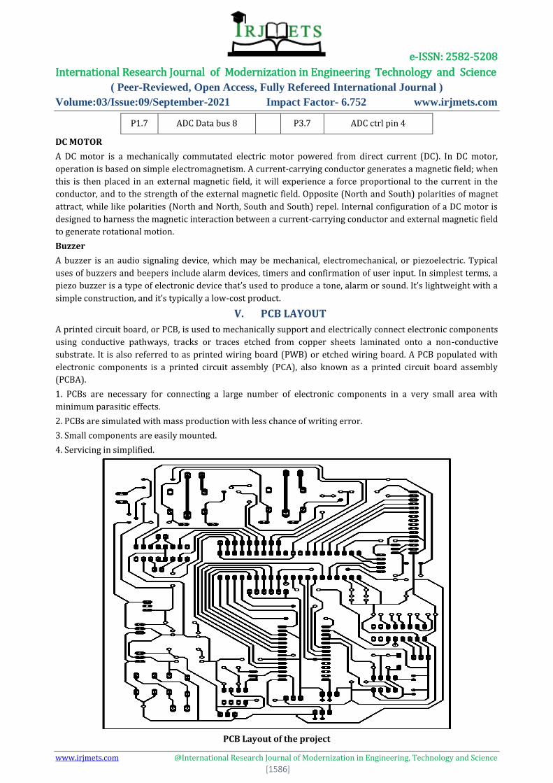
V. PCB LAYOUT
A printed circuit board, or PCB, is used to mechanically support and electrically connect electronic components
using conductive pathways, tracks or traces etched from copper sheets laminated onto a non-conductive
substrate. It is also referred to as printed wiring board (PWB) or etched wiring board. A PCB populated with
electronic components is a printed circuit assembly (PCA), also known as a printed circuit board assembly
(PCBA).
1. PCBs are necessary for connecting a large number of electronic components in a very small area with
minimum parasitic effects.
2. PCBs are simulated with mass production with less chance of writing error.
3. Small components are easily mounted.
4. Servicing in simplified.
PCB Layout of the project
e-ISSN: 2582-5208 International Research Journal of Modernization in Engineering Technology and Science
( Peer-Reviewed, Open Access, Fully Refereed International Journal )
Volume:03/Issue:09/September-2021 Impact Factor- 6.752 www.irjmets.com
www.irjmets.com @International Research Journal of Modernization in Engineering, Technology and Science
[1587]
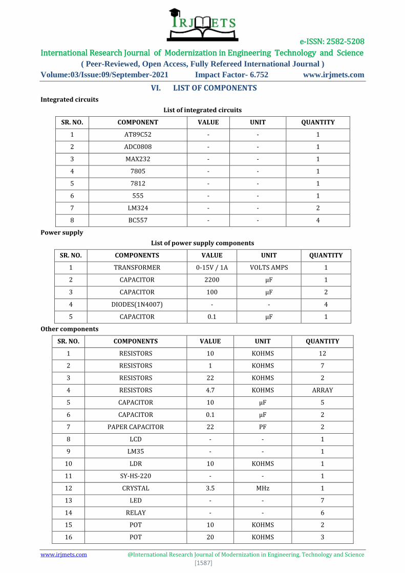
VI. LIST OF COMPONENTS
Integrated circuits
List of integrated circuits
SR. NO. COMPONENT VALUE UNIT QUANTITY
1 AT89C52 - - 1
2 ADC0808 - - 1
3 MAX232 - - 1
4 7805 - - 1
5 7812 - - 1
6 555 - - 1
7 LM324 - - 2
8 BC557 - - 4
Power supply
List of power supply components
SR. NO. COMPONENTS VALUE UNIT QUANTITY
1 TRANSFORMER 0-15V / 1A VOLTS AMPS 1
2 CAPACITOR 2200 µF 1
3 CAPACITOR 100 µF 2
4 DIODES(1N4007) - - 4
5 CAPACITOR 0.1 µF 1
Other components
SR. NO. COMPONENTS VALUE UNIT QUANTITY
1 RESISTORS 10 KOHMS 12
2 RESISTORS 1 KOHMS 7
3 RESISTORS 22 KOHMS 2
4 RESISTORS 4.7 KOHMS ARRAY
5 CAPACITOR 10 µF 5
6 CAPACITOR 0.1 µF 2
7 PAPER CAPACITOR 22 PF 2
8 LCD - - 1
9 LM35 - - 1
10 LDR 10 KOHMS 1
11 SY-HS-220 - - 1
12 CRYSTAL 3.5 MHz 1
13 LED - - 7
14 RELAY - - 6
15 POT 10 KOHMS 2
16 POT 20 KOHMS 3
e-ISSN: 2582-5208 International Research Journal of Modernization in Engineering Technology and Science
( Peer-Reviewed, Open Access, Fully Refereed International Journal )
Volume:03/Issue:09/September-2021 Impact Factor- 6.752 www.irjmets.com
www.irjmets.com @International Research Journal of Modernization in Engineering, Technology and Science
[1588]
17 POT 4.7 KOHMS 1
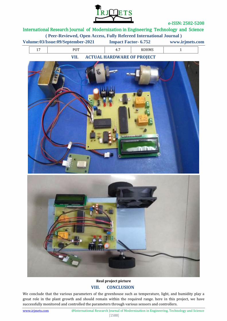
VII. ACTUAL HARDWARE OF PROJECT
Real project picture
VIII. CONCLUSION
We conclude that the various parameters of the greenhouse such as temperature, light, and humidity play a
great role in the plant growth and should remain within the required range. here in this project, we have
successfully monitored and controlled the parameters through various sensors and controllers.
e-ISSN: 2582-5208 International Research Journal of Modernization in Engineering Technology and Science
( Peer-Reviewed, Open Access, Fully Refereed International Journal )
Volume:03/Issue:09/September-2021 Impact Factor- 6.752 www.irjmets.com
www.irjmets.com @International Research Journal of Modernization in Engineering, Technology and Science
[1589]
This is one of the important projects amongst various agriculture projects for engineering students. This
project consists of temperature, humidity monitoring & controlling and light monitoring. This unit is installed
on a robot which moves through the greenhouse on a predefined track. This High technology farming project
will consist of three basis modules. First is “Parameters Monitoring” second is “Parameters Controlling” and
third is automatic movement of Robot on a predefined path.
IX. REFERENCES [1] Ganesh Kumar and Vasanth Sena, “Novel Artificial Neural Networks and Logistic Approach for
Detecting Credit Card Deceit,” International Journal of Computer Science and Network Security, Vol. 15,
issue 9, Sep. 2015, pp. 222-234
[2] Gyusoo Kim and Seulgi Lee, “2014 Payment Research”, Bank of Korea, Vol. 2015, No. 1, Jan. 2015.
[3] Chengwei Liu, Yixiang Chan, Syed Hasnain Alam Kazmi, Hao Fu, “Financial Fraud Detection Model:
Based on Random Forest,” International Journal of Economics and Finance, Vol. 7, Issue. 7, pp. 178-188,
2015.
[4] Hitesh D. Bambhava, Prof. Jayeshkumar Pitroda, Prof. Jaydev J. Bhavsar (2013), “A Comparative Study
on Bamboo Scaffolding and Metal Scaffolding in Construction Industry Using Statistical Methods”,
International Journal of Engineering Trends and Technology (IJETT) – Volume 4, Issue 6, June 2013,
Pg.2330-2337.
[5] P. Ganesh Prabhu, D. Ambika, “Study on Behaviour of Workers in Construction Industry to Improve
Production Efficiency”, International Journal of Civil, Structural, Environmental and Infrastructure
Engineering Research and Development (IJCSEIERD), Vol. 3, Issue 1, Mar 2013, 59-66
BOOKS:
[6] Kenneth. J. Ayala – The 8051 Micro-Controller.
[7] Douglas Hal
[8] PHILIPS Handbook
[9] Lampex.
[10] N. C. Goyal -R. K. Khaitan – A Monograph on Electronics Design Principles
[11] R. S. Gaonkar.
[12] U.P Bakshi - A.P Godse- Integrated Circuits and Applications
WEBSITES:
[13] www.ATMEL.com
[14] www.nsc.com
[15] www.spj.com