Embed Size (px)
Citation preview

0
Mitsubishi Smart Grid Activities
December 10, 2012
Yasuhiro Kojima
Mitsubishi Electric Corporation
Green Technology WS

1
Grid Operation Challenges caused by Renewable Energy Penetration
Challenge Reason Technical Solution
1
Frequency Deviation Unstable output from renewable (PhotoVoltaic
and Wind Turbine)
•
Forecasting
•
Control for PV and WT
•
Hydro Optimization (Variable Speed
Pumped Storage)
•
Installation of Battery
2
Excess Power A large amount of unstable output from PV and WT at low load period (Weekend of Spring)
•
Installation of Battery
•
Control for PV and Wind
•
EV utilization
•
Demand Response
3
Over Voltage, Voltage Deviation Excess power output from individual PV panel in the feeder
•Installation of Local Voltage Regulator
•Control for PV
•Optimal Power Flow (Central Control)

2
Smart Grid
Generation(Conventional)
Trans. & Dis. Consumers(Factory/Building/house)
<Current>
<Smart Grid>
Generation(Conventional)
Trans. & Dis. Consumers(Factory/Building/house)
Generation (Renewable)Wind Photovoltaic Battery
(local)
Battery
Battery Photovoltaic
EVHeat pump
Smart Meter
BEMS
Information Network
Electricity Electricity
ElectricityElectricity
Renewable Progressing Renewable Progressing
Demand Response with IT
Demand Response with IT
Grid Reinforcement
Grid Reinforcement

3
Balance ManagementBalance Management
Distribution ManagementDistribution Management
Advance metering Infra.Advance metering Infra.
Bulk System(22kV~500kV)
Power Plants, UHV and HV transmission system
Distribution(100/200V、6.6kV)
Medium /Low voltage distribution network
Demand(100/200V)Building, Residential Houses, EV
Central Control Center
Large Size Battery
Distribution Management NetworkDistribution Management Network
Intelligent Switch
Hydro Plant Nuclear PlantWTThermal Plant
Large Scale Photovoltaic
SVG
SubstationSVC
SVR
Photovoltaic
Battery
Smart Meter Access NetworkSmart Meter Access Network
Smart Grid Test Facility: Scope and System
Energy Management SystemEnergy Management System
Smart Meter
Concentrator
Demand
Distribution
Bulk System

4
Project Objective
The test facility was develop with the intent to have a real analog power system to simulate and verify the performances of algorithms and equipment under the following conditions;
• Political changes (deregulation, interconnection requirements, FIT, wheeling rules)• Business environment changes (power system management, regional distributed resources).• Climate changes (solar radiation, wind speed, temperature, etc.)• Severe power system conditions (earth fault, short circuit, generator fault)
Mitsubishi intend to find the specific requirements to keep the future power system economical and stable, and to provide and validate solutions in the real field
5
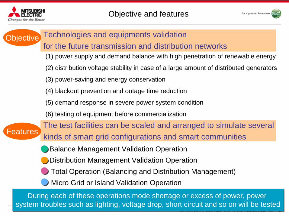
Technologies and equipments validation for the future transmission and distribution networks
Objective and features
The test facilities can be scaled and arranged to simulate several kinds of smart grid configurations and smart communities
Balance Management Validation OperationDistribution Management Validation OperationTotal Operation (Balancing and Distribution Management)Micro Grid or Island Validation Operation
During each of these operations mode shortage or excess of power, power system troubles such as lighting, voltage drop, short circuit and so on will be tested
During each of these operations mode shortage or excess of power, power system troubles such as lighting, voltage drop, short circuit and so on will be tested
Objective
Features
(1) power supply and demand balance with high penetration of renewable energy
(2) distribution voltage stability in case of a large amount of distributed generators
(3) power-saving and energy conservation
(4) blackout prevention and outage time reduction
(5) demand response in severe power system condition
(6) testing of equipment before commercialization
6
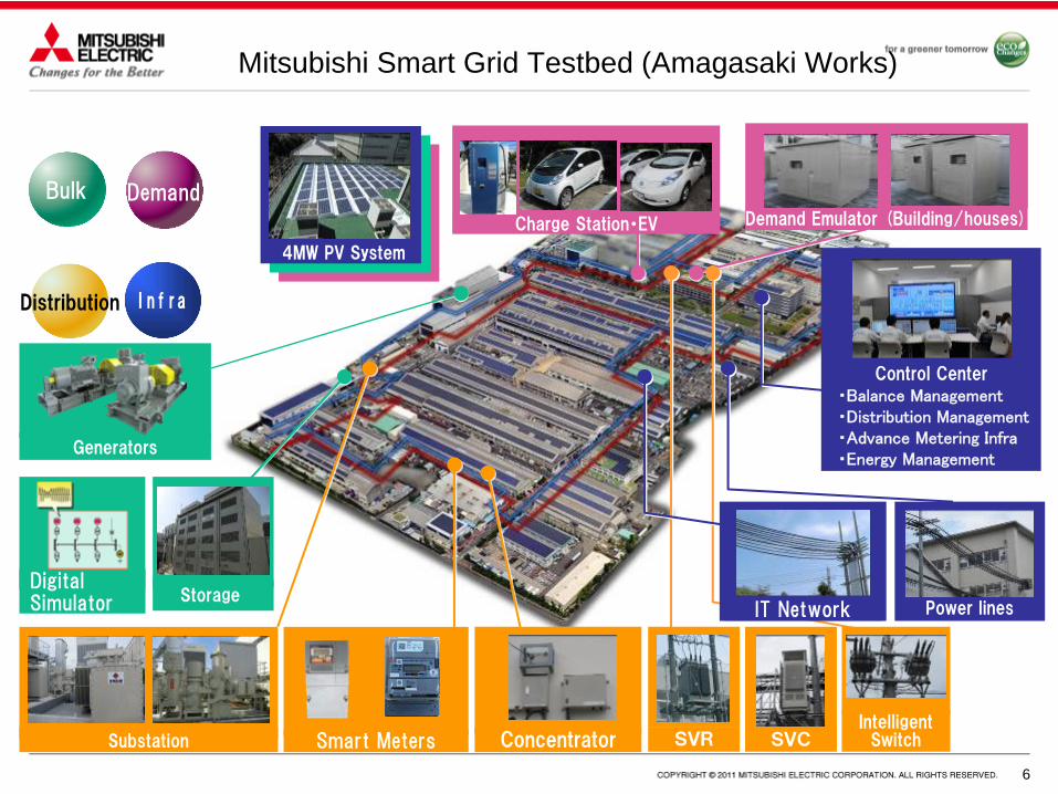
Mitsubishi Smart Grid Testbed (Amagasaki Works)
Bulk
Distribution
DemandDemand Emulator (Building/houses)
Generators
Digital Simulator
Smart MetersSubstation Concentrator
Infra
IT Network
Control Center・Balance Management・Distribution Management・Advance Metering Infra・Energy Management
4MW PV System
Power lines
SVCSVRIntelligent
Switch
Storage
Charge Station・EV
77
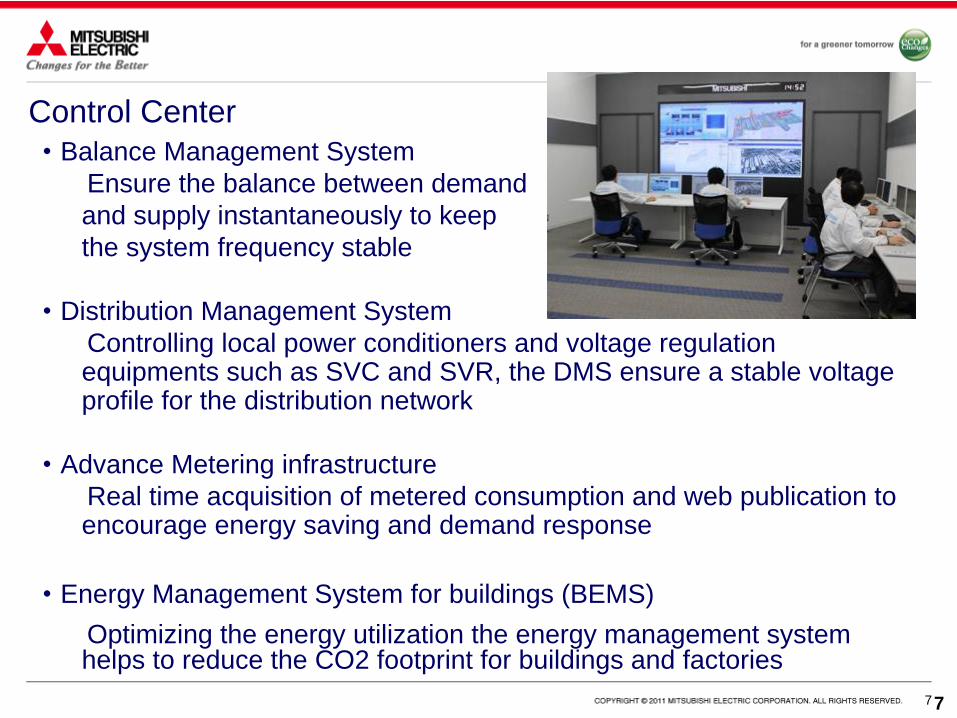
・Balance Management SystemEnsure the balance between demand and supply instantaneously to keep the system frequency stable
・Distribution Management SystemControlling local power conditioners and voltage regulation equipments such as SVC and SVR, the DMS ensure a stable voltage profile for the distribution network
・Advance Metering infrastructureReal time acquisition of metered consumption and web publication to encourage energy saving and demand response
・Energy Management System for buildings (BEMS)Optimizing the energy utilization the energy management system helps to reduce the CO2 footprint for buildings and factories
Control Center

8
Assets
System/equipment Characteristics
Infra- structure
Large Scale Photovoltaic System (4,000kW)
5 types of PV Power Conditioner (5kW for home use, 10kW, 100kW, 250kW and 500kW for commercial use)
Distribution network(6.6kV, 7km-16km)
A real distribution network for testing propose. The length can be adapted based on the type of test
Communication Network 3 types of communication network: high speed optical fiber, metal cable and wireless
Bulk system
Balance Management System Optimal balance control system for thermal and hydro generators, batteries and PV
Digital simulator and BTB Connected digital and analog power network with a BTB to simulate many power network situation (West Japan area, Kansai, island, fault, etc.)
Variable Speed Pump StorageThermal GeneratorBatteries(NAS: 500kW、Li-ion: 250kW)
A set of generation assets to simulate several kind of power system
BTB: Back to Back (AC-DC-AC converter)

9
System/Asset CharacteristicsDistribution Next Generation
Distribution Management System
Next generation DAS, includes voltage control, loss minimization power flow and phase unbalance monitoring
Instantaneous switching equipmentIntelligent switch
Switching equipment that allowed the switching from one feeder to another without black out and collect power system information
Advance Metering Infrastructure
Mesh network based AMI supporting 429 and 950MHz band
Smart Meters (150) Smart meter to monitor real time consumption of offices and factories
Demand Demand Emulator Programmable active and reactive demand to create several scenarios
Assets

10
-Power System Stability Control and Optimal Energy Dispatch-Distribution Management-Metering Management-Demand Side Management
Smart Grid Management Systems

● Large amount of photovoltaic may cause imbalance in the production and a consequent deterioration of the power quality
● Optimal dispatch of the supply resource coordinating thermal power plants, pump storage plants and batteries
● The dispatch and control algorithm was tested in a scenario with high penetration of photovoltaic and the power quality level (frequency within +/-0.2Hz from nominal value) was ensured
Time
Pow
er
Generation
Time
Pow
er
Thermal Pump Storage Batteries
Balance Management
System
Photovoltaic
Pow
er
Coordination of Batteries and controllable plants Weather Dependent
Demand Frequency- +
Nuclear→Fix
Production
Pow
er
Distributed ResourceControl Signal
Demand Supply Balance Management

12
Hierarchal Recursive Monitoring and Control• Large amount of resources have to be
monitored and controlled. In addition resources can be owned and operated by different organization.
• Coordination and standardization of operation needed
- Hierarchal object-oriented definition of operation cell. Each cell may contain loads, batteries, and distributed generators.
- Each cell may contain another cell with the same conceptual definition.
- Each cell is operated by a control system that interface with each element of the cell and with another cell or the central control center
- The control system can operate the cell in independent mode or follow the instruction of the upper cell or of the central control center.
Conventional Generation
Dispatch and Control (Central)
Distributed Generation
Operational Cell

13
Local Voltage Control with Conventional and Power Electronics Devices
SVRDistributed Generator
L
Building, Factory etc.
Target point
Voltage at SVR
Is=0
G=L=Max
G=L=0
SVR (SVC) can detect only voltage at its location. Voltage at Target point can be strongly
Vs Vc
Vs
Vc?
G
LRTL
L
Feeder 2
Feeder 1 Several PV
Voltage
Distance
Upper Limit
Lower Limit
Voltage Feeder 1
Voltage Feeder 2
• Distributed generators affect the distribution network voltage. It is expected an increase of voltage and high fluctuation in the profile.
• Voltage increase may cause damage to customers appliances and PV stopping.
- Power electronic devices able to monitor the voltage locally and to supply or absorb reactive power can be a solution to the challenge:
1) LRT (Load Ratio Control Transformer)2) SVR (Step Voltage Regulator)3) SVC (Static Var Compensator)
-Location and sizing of the devices are designed using power flow simulation
14
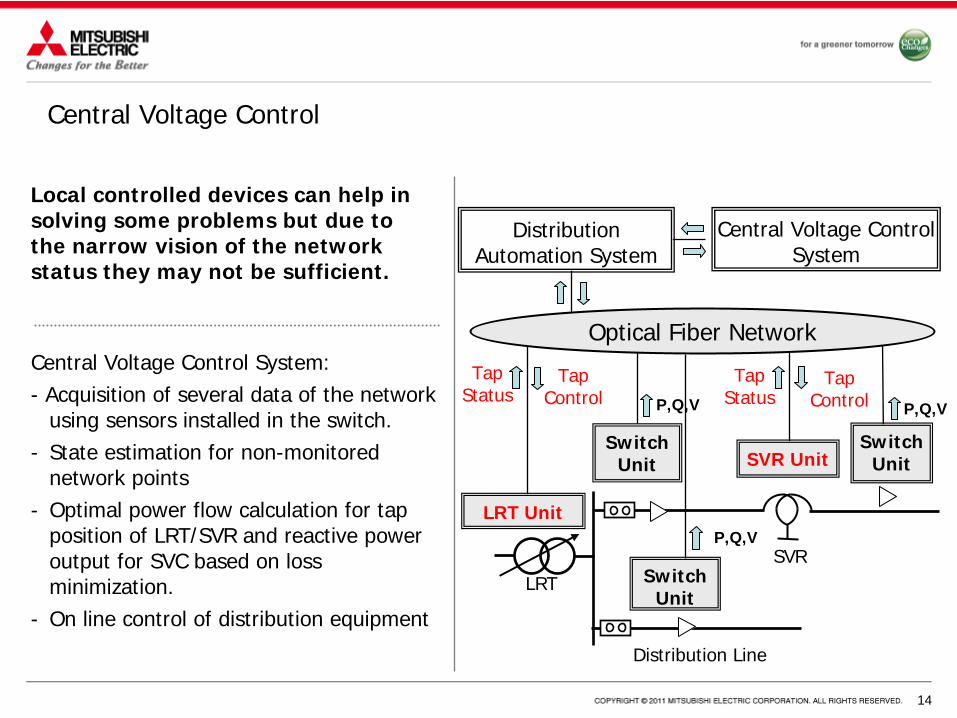
Central Voltage Control
P,Q,V
Central Voltage Control System
LRT
Distribution Line
SVR
Switch Unit
Switch Unit SVR Unit
LRT Unit
Tap Status
Tap Control
P,Q,V
P,Q,V
Distribution Automation System
Switch Unit
Optical Fiber Network
Tap Status
Tap Control
Local controlled devices can help in solving some problems but due to the narrow vision of the network status they may not be sufficient.
Central Voltage Control System:- Acquisition of several data of the network
using sensors installed in the switch.- State estimation for non-monitored
network points- Optimal power flow calculation for tap
position of LRT/SVR and reactive power output for SVC based on loss minimization.
- On line control of distribution equipment

15
IP Network
Consol
Brunch Office
ITC Consol
Brunch Office
ITC Consol
Brunch Office
ITC
AMI server
DistributionAutomation
・Demand management・Voltage management・Planning・DG monitoring・Forecast
Applicationserver
Central control center
Distribution Management

16
Smart Metering
Smart Meter
GW
Smart Meter Device(1million - 10 million)
GW
(thousands of)
Dedicated line
(IP network)
Public network
(IP network)
Handy Terminal
Data Collector Data Management
Network Management
Smart Metering FunctionInterval metering(15,30,60min)
On demand metering
Remote connect/disconnect
Outage management
Flexible tariff
Demand response
Home Gateway
Operation Center

17
Smart Grid/Smart Community Concept
Compatibility between a low-carbon society and prosperous lifestyles: Smart community/Smart gridRealize optimal energy control integrating Mitsubishi Electric’s expertise in all areas,
from power systems to consumer electronics