Embed Size (px)
Citation preview

Working Version
Green Cleaning
A Handbook on Designing an Environmentally Friendly
Milking Machine CIP System
August 2008
Gabriel Hakim
AgVet Projects PO Box 1390
Warragul, 3820
AUSTRALIA
www.agvetprojects.com.au This version: July 29, 2010
Milking Machine CIP Almanac July 29.docx
Working Version July 29, 2010 Page 2 of 36
Acknowledgements
I wish to acknowledge the following publications were valuable resources and were
extensively referred to in the preparation of this almanac.
Dairy hygiene and detergent handbook (2000) Alfa Laval Agri, Australia
Allinson G, Dyer M (2007). Closing the Loop: An holistic approach to the management of
dairy processor waste streams. Progress Report 8 (Final Report). Department of
Primary Industries, Queenscliff, Australia.
Weeks M, Issa J, Warren S, Knight G (2004) Closing the Loop: An holistic approach to the
management of dairy processor waste streams. Review of Products and Processes
to reduce Sodium Usage in Dairy CIP Manufacturing Procedures. Milestone Report
1. Department of Primary Industries, Queenscliff, Australia.
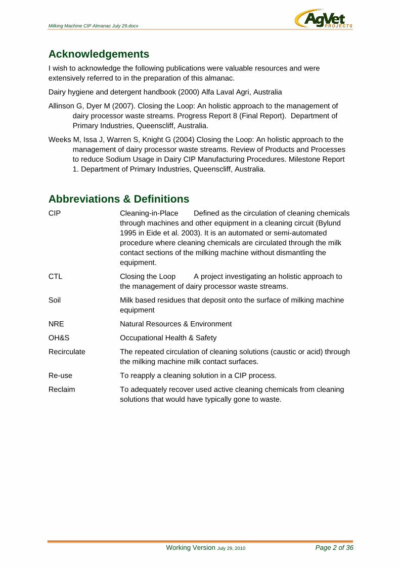
Abbreviations & Definitions
CIP Cleaning-in-Place Defined as the circulation of cleaning chemicals
through machines and other equipment in a cleaning circuit (Bylund
1995 in Eide et al. 2003). It is an automated or semi-automated
procedure where cleaning chemicals are circulated through the milk
contact sections of the milking machine without dismantling the
equipment.
CTL Closing the Loop A project investigating an holistic approach to
the management of dairy processor waste streams.
Soil Milk based residues that deposit onto the surface of milking machine
equipment
NRE Natural Resources & Environment
OH&S Occupational Health & Safety
Recirculate The repeated circulation of cleaning solutions (caustic or acid) through
the milking machine milk contact surfaces.
Re-use To reapply a cleaning solution in a CIP process.
Reclaim To adequately recover used active cleaning chemicals from cleaning
solutions that would have typically gone to waste.

Milking Machine CIP Almanac July 29.docx
Working Version July 29, 2010 Page 3 of 36
Table of Contents Acknowledgements ............................................................................................................... 2
Abbreviations & Definitions ................................................................................................... 2
Introduction ........................................................................................................................... 5
Principles of Cleaning ........................................................................................................... 6
Water .................................................................................................................................... 7
Water Quality ................................................................................................................. 7
Water Quantity ............................................................................................................... 8
Cleaning Procedure .............................................................................................................. 9
Existing Cleaning Cycles ................................................................................................... 9
Chemicals ....................................................................................................................... 10
CIP Mechanics ................................................................................................................ 10
Performance Monitoring Systems .................................................................................... 11
Energy Inputs ...................................................................................................................... 12
Feature Prerequisites .......................................................................................................... 13
Design ................................................................................................................................ 14
Dosing & Filling ............................................................................................................ 14
Heating the Rinse Cycle ............................................................................................... 15
Heating the Wash Cycle ............................................................................................... 17
Wash Suction Line ....................................................................................................... 18
Wash Return Line ........................................................................................................ 19
The Complete System.................................................................................................. 20
The Rinse Tank............................................................................................................ 21
The Wash Tanks .......................................................................................................... 22
The Software Program ................................................................................................. 23
Renewable Sources ........................................................................................................ 24
Proposed Cleaning Cycle ................................................................................................ 24
Valves, Senses & Switches .......................................................................................... 25
References ......................................................................................................................... 25
Appendix ............................................................................................................................. 26
Program Specifications & Description .............................................................................. 26
Functional Description - Overview. ...................................................................................... 29
PC + Software. ................................................................................................................ 29
Touch Screen. ................................................................................................................. 30
1WB Interface (EDS HA7E). ............................................................................................ 30
Temperature Sensor. ....................................................................................................... 30
Float Switch Input. ........................................................................................................... 30
Milking Machine CIP Almanac July 29.docx
Working Version July 29, 2010 Page 4 of 36
Control Outputs. .............................................................................................................. 31
Analogue Input. ............................................................................................................... 31
Power Supply. ................................................................................................................. 31
System Name Cross-Reference. ......................................................................................... 32
Suitability checklist for a Green Cleaning trial site ........................................................... 33
Water............................................................................................................................... 34
Floor Space ..................................................................................................................... 34
Milking Machines ............................................................................................................. 34
Renewable Energy Sources ............................................................................................ 35
Milk Quality ...................................................................................................................... 36
OH & S ............................................................................................................................ 36

Milking Machine CIP Almanac July 29.docx
Working Version July 29, 2010 Page 5 of 36
Introduction
The principles of cleaning milking machines have not changed over the last twenty years or
more. Dairies around the world apply these same principles, albeit with localised
interpretations. What has changed is the manner in which milking machines are cleaned.
Cleaning in place (CIP) has been for at least the last 15 years the universal way to wash
milking machines in Australia. It is labour and water efficient and much safer than the
alternatives of “reverse flow” and “bucket cleaning”.
Technology and automation have also helped to make cleaning easier and more consistent.
Modern dairies now use automated systems that control chemical dosing, water volumes,
wash cycles, temperatures as well as monitoring and alerting on system performance. It is a
vast difference to the bucket cleaning method employed only 15 years ago.
This change in the way milking machines are cleaned, as opposed to principles of cleaning,
is reflected in the literature. Research over the last decade has predominantly focused on
refining cleaning system performance, for example, improving slug flow conditions, and
improving the analysis and interpretation of cleaning assessment procedures.
The thrust of the Green Cleaning project is to inject the principles of energy and water
efficiency into the CIP systems used in Australian dairies. The project will develop an
energy efficient re-use CIP system that can be used as a product in its own right or
preferably as a platform for exploitation by the commercial sector.
Either way the project’s ultimate aim is to have available “on the shelf” CIP product(s) that
will reduce the environmental footprint of Australian dairy farms.
Milking Machine CIP Almanac July 29.docx
Working Version July 29, 2010 Page 6 of 36
Principles of Cleaning
Regardless of the techniques employed, or the layout of the milking equipment, there are six
key elements that are fundamental to the success in cleaning a milking machine. Whether it
is a “bucket milker” or a 100 unit fully automated dairy these basic principles of cleaning
remain the same.
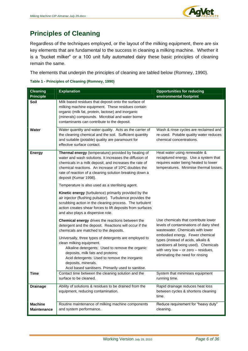
The elements that underpin the principles of cleaning are tabled below (Romney, 1990).
Table 1 - Principles of Cleaning (Romney, 1990)
Cleaning
Principle
Explanation Opportunities for reducing
environmental footprint
Soil Milk based residues that deposit onto the surface of
milking machine equipment. These residues contain
organic (milk fat, protein, lactose) and inorganic
(minerals) compounds. Microbial and water borne
contaminants can contribute to the deposit.
Water Water quantity and water quality. Acts as the carrier of
the cleaning chemical and the soil. Sufficient quantity
and suitable (potable) quality are paramount for
effective surface contact.
Wash & rinse cycles are reclaimed and
re-used. Potable quality water reduces
chemical concentrations.
Energy Thermal energy (temperature) provided by heating of
water and wash solutions. It increases the diffusion of
chemicals in a milk deposit, and increases the rate of
chemical reactions. An increase of 10ºC doubles the
rate of reaction of a cleaning solution breaking down a
deposit (Kumar 1998).
Temperature is also used as a sterilising agent.
Kinetic energy (turbulence) primarily provided by the
air injector (flushing pulsator). Turbulence provides the
scrubbing action in the cleaning process. The turbulent
action creates shear forces to lift deposits from surfaces
and also plays a dispersive role.
Chemical energy drives the reactions between the
detergent and the deposit. Reactions will occur if the
chemicals are matched to the deposits.
Universally, three types of detergents are employed to
clean milking equipment.
Alkaline detergents: Used to remove the organic
deposits, milk fats and proteins;
Acid detergents: Used to remove the inorganic
deposits, minerals.
Acid based sanitisers. Primarily used to sanitise.
Heat water using renewable &
recaptured energy. Use a system that
requires water being heated to lower
temperatures. Minimise thermal losses.
Use chemicals that contribute lower
levels of contaminations of dairy shed
wastewater. Chemicals with lower
embodied energy. Fewer chemical
types (instead of acids, alkalis &
sanitisers all being used). Chemicals
with very low – or zero – residues,
eliminating the need for rinsing
Time Contact time between the cleaning solution and the
surface to be cleaned.
System that minimises equipment
running time.
Drainage Ability of solutions & residues to be drained from the
equipment, reducing contamination.
Rapid drainage reduces heat loss
between cycles & shortens cleaning
time.
Machine
Maintenance
Routine maintenance of milking machine components
and system performance.
Reduce requirement for “heavy duty”
cleaning.
Milking Machine CIP Almanac July 29.docx
Working Version July 29, 2010 Page 7 of 36
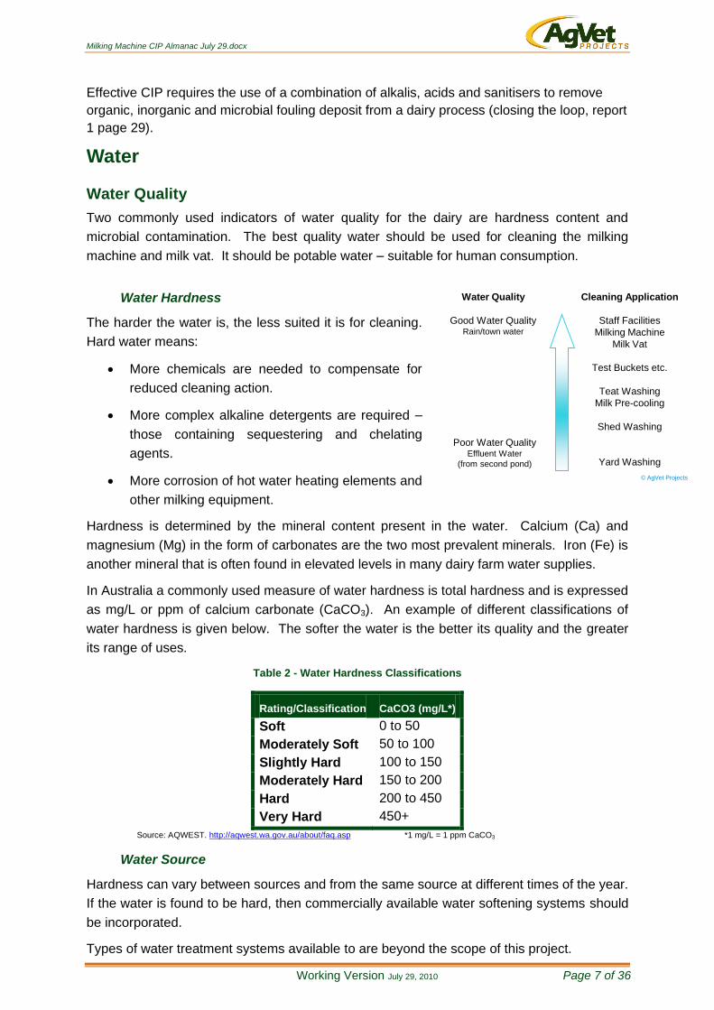
Water Quality
Good Water QualityRain/town water
Poor Water QualityEffluent Water
(from second pond)
Cleaning Application
Staff Facilities
Milking Machine
Milk Vat
Test Buckets etc.
Teat Washing
Milk Pre-cooling
Shed Washing
Yard Washing
© AgVet Projects
Effective CIP requires the use of a combination of alkalis, acids and sanitisers to remove
organic, inorganic and microbial fouling deposit from a dairy process (closing the loop, report
1 page 29).
Water
Water Quality
Two commonly used indicators of water quality for the dairy are hardness content and
microbial contamination. The best quality water should be used for cleaning the milking
machine and milk vat. It should be potable water – suitable for human consumption.
Water Hardness
The harder the water is, the less suited it is for cleaning.
Hard water means:
More chemicals are needed to compensate for
reduced cleaning action.
More complex alkaline detergents are required –
those containing sequestering and chelating
agents.
More corrosion of hot water heating elements and
other milking equipment.
Hardness is determined by the mineral content present in the water. Calcium (Ca) and
magnesium (Mg) in the form of carbonates are the two most prevalent minerals. Iron (Fe) is
another mineral that is often found in elevated levels in many dairy farm water supplies.
In Australia a commonly used measure of water hardness is total hardness and is expressed
as mg/L or ppm of calcium carbonate (CaCO3). An example of different classifications of
water hardness is given below. The softer the water is the better its quality and the greater
its range of uses.
Table 2 - Water Hardness Classifications
Rating/Classification CaCO3 (mg/L*)
Soft 0 to 50
Moderately Soft 50 to 100
Slightly Hard 100 to 150
Moderately Hard 150 to 200
Hard 200 to 450
Very Hard 450+
Source: AQWEST. http://aqwest.wa.gov.au/about/faq.asp *1 mg/L = 1 ppm CaCO3
Water Source
Hardness can vary between sources and from the same source at different times of the year.
If the water is found to be hard, then commercially available water softening systems should
be incorporated.
Types of water treatment systems available to are beyond the scope of this project.
Milking Machine CIP Almanac July 29.docx
Working Version July 29, 2010 Page 8 of 36
Water Quality Parameters
The water quality to use in a re-use system should have a hardness of <150ppm (CaCO3)
and an iron level of less than 0.5 ppm.
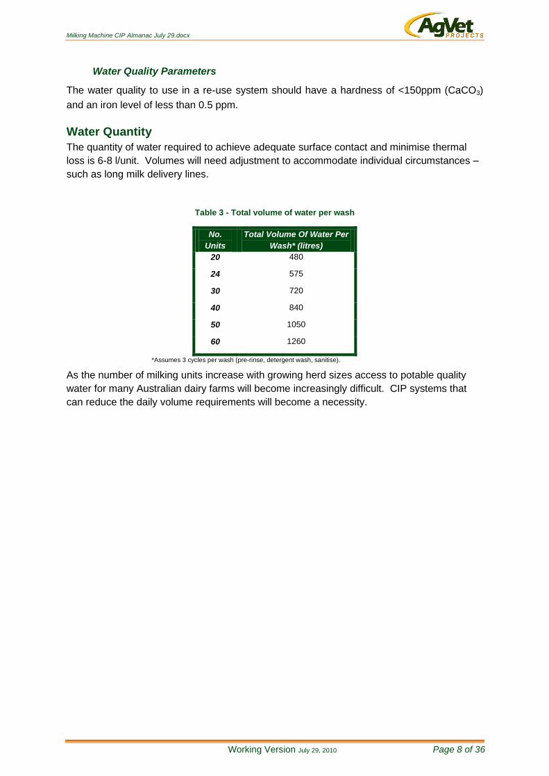
Water Quantity
The quantity of water required to achieve adequate surface contact and minimise thermal
loss is 6-8 l/unit. Volumes will need adjustment to accommodate individual circumstances –
such as long milk delivery lines.
Table 3 - Total volume of water per wash
No.
Units
Total Volume Of Water Per
Wash* (litres)
20 480
24 575
30 720
40 840
50 1050
60 1260
*Assumes 3 cycles per wash (pre-rinse, detergent wash, sanitise).
As the number of milking units increase with growing herd sizes access to potable quality
water for many Australian dairy farms will become increasingly difficult. CIP systems that
can reduce the daily volume requirements will become a necessity.
Milking Machine CIP Almanac July 29.docx
Working Version July 29, 2010 Page 9 of 36
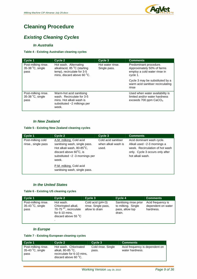
Cleaning Procedure
Existing Cleaning Cycles
In Australia
Table 4 - Existing Australian cleaning cycles
In New Zealand
Table 5 - Existing New Zealand cleaning cycles
In the United States
Table 6 - Existing US cleaning cycles
Cycle 1 Cycle 2 Cycle 3 Cycle 4 Comments
Post-milking rinse. 35-43
oC, single
pass
Hot wash. Chlorinated alkali, 70-75
oC, recirculate
for 6-10 mins, discard above 55
oC
.
Cold acid (pH<3) rinse. Single pass, allow to drain
Sanitising rinse prior to milking. Single pass, allow top drain.
Acid frequency is dependent on water hardness.
In Europe
Table 7 - Existing European cleaning cycles
Cycle 1 Cycle 2 Cycle 3 Comments
Post-milking rinse. 35-43
oC, single
pass
Hot wash. Chlorinated alkali, 80-85
oC,
recirculate for 6-10 mins, discard above 60
oC.
Cold rinse. Single pass.
Acid frequency is dependent on water hardness.
Cycle 1 Cycle 2 Cycle 3 Comments
Post-milking rinse. 35-38
oC, single
pass
Hot wash. Alternating alkali/acid, 85
oC (starting
temp), recirculate for 3-5 mins, discard above 60
oC.
Hot water rinse. Single pass.
Predominant procedure. Approximately 50% of farms employ a cold water rinse in cycle 1.
Cycle 3 may be substituted by a warm acid sanitiser recirculating rinse
Post-milking rinse. 35-38
oC, single
pass
Warm-hot acid sanitising wash. Recirculate for 3-5 mins. Hot alkali wash is substituted ~2 milkings per week.
Used when water availability is limited and/or water hardness exceeds 700 ppm CaCO3.
Cycle 1 Cycle 2 Cycle 3 Comments
Post-milking cold
rinse., single pass
A.M. milking. Cold acid
sanitising wash, single pass.
Hot alkali wash, 80-85oC,
discard above 60oC, is
substituted ~2 -3 mornings per
week.
P.M. milking. Cold acid
sanitising wash, single pass.
Cold acid sanitiser
when alkali wash is
used.
Acid dominant wash cycle.
Alkali used ~2-3 mornings a
week. Recirculation of hot wash
only. Cycle 3 occurs only after
hot alkali wash.
Milking Machine CIP Almanac July 29.docx
Working Version July 29, 2010 Page 10 of 36
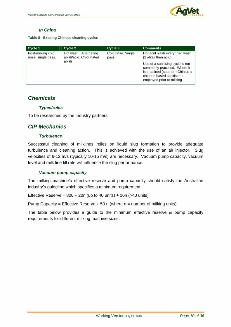
In China
Table 8 - Existing Chinese cleaning cycles
Chemicals
Types/roles
To be researched by the Industry partners.
CIP Mechanics
Turbulence
Successful cleaning of milklines relies on liquid slug formation to provide adequate
turbulence and cleaning action. This is achieved with the use of an air injector. Slug
velocities of 6-12 m/s (typically 10-15 m/s) are necessary. Vacuum pump capacity, vacuum
level and milk line fill rate will influence the slug performance.
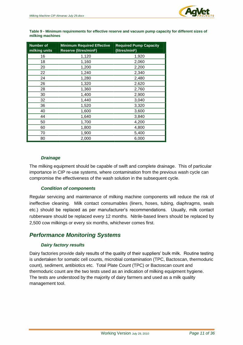
Vacuum pump capacity
The milking machine’s effective reserve and pump capacity should satisfy the Australian
industry’s guideline which specifies a minimum requirement.
Effective Reserve = 800 + 20n (up to 40 units) + 10n (>40 units)
Pump Capacity = Effective Reserve + 50 n (where n = number of milking units).
The table below provides a guide to the minimum effective reserve & pump capacity
requirements for different milking machine sizes.
Cycle 1 Cycle 2 Cycle 3 Comments
Post-milking cold rinse, single pass.
Hot wash. Alternating alkali/acid. Chlorinated alkali
Cold rinse. Single pass.
Hot acid wash every third wash (2 alkali then acid).
Use of a sanitising cycle is not commonly practiced. Where it is practiced (southern China), a chlorine based sanitiser is employed prior to milking.
Milking Machine CIP Almanac July 29.docx
Working Version July 29, 2010 Page 11 of 36
Table 9 - Minimum requirements for effective reserve and vacuum pump capacity for different sizes of
milking machines
Number of
milking units
Minimum Required Effective
Reserve (litres/minF)
Required Pump Capacity
(litres/minF)
16 1,120 1,920
18 1,160 2,060
20 1,200 2,200
22 1,240 2,340
24 1,280 2,480
26 1,320 2,620
28 1,360 2,760
30 1,400 2,900
32 1,440 3,040
36 1,520 3,320
40 1,600 3,600
44 1,640 3,840
50 1,700 4,200
60 1,800 4,800
70 1,900 5,400
80 2,000 6,000
Drainage
The milking equipment should be capable of swift and complete drainage. This of particular
importance in CIP re-use systems, where contamination from the previous wash cycle can
compromise the effectiveness of the wash solution in the subsequent cycle.
Condition of components
Regular servicing and maintenance of milking machine components will reduce the risk of
ineffective cleaning. Milk contact consumables (liners, hoses, tubing, diaphragms, seals
etc.) should be replaced as per manufacturer’s recommendations. Usually, milk contact
rubberware should be replaced every 12 months. Nitrile-based liners should be replaced by
2,500 cow milkings or every six months, whichever comes first.
Performance Monitoring Systems
Dairy factory results
Dairy factories provide daily results of the quality of their suppliers’ bulk milk. Routine testing
is undertaken for somatic cell counts, microbial contamination (TPC, Bactoscan, thermoduric
count), sediment, antibiotics etc. Total Plate Count (TPC) or Bactoscan count and
thermoduric count are the two tests used as an indication of milking equipment hygiene.
The tests are understood by the majority of dairy farmers and used as a milk quality
management tool.

Milking Machine CIP Almanac July 29.docx
Working Version July 29, 2010 Page 12 of 36
Table 10 - Example of milk quality criteria thresholds used by Victorian dairy factories
Parameter Premium Grade Standard Grade Sub-standard Grade
Total Plate Count (cfu/ml) <20,000 20,000 – 50,000 >50,000
Bactoscan ≤80,000 >80,000 - ≤200,000 >200,000
Thermodurics (cfu/ml) <2,000 2,000 – 5,000 >5,000
Thermophiles (cfu/ml) <1,000 1,000 – 5,000 >5,000
Manual/visual procedures
Physical and visual inspection of milk contact surfaces remains an integral tool to evaluate
cleaning effectiveness. Inspection involves systematic dismantling of milking machine
components to identify any deposits. The type of deposit (protein based, fat based, mineral
based) and where it is located will highlight cleaning performance deficiencies.
Commercial Diagnostic Tests
ATP bioluminescence is diagnostic test that can be used to estimate the cleanliness of
surfaces. Its application and usefulness in the dairy industry was reviewed by Griffiths
(1993). It is extensively used throughout the food and health care industries and scores of
ATP test kits are commercially available. However, the extreme variability of farm
environmental conditions and test results limit their suitability for assessing the hygiene
status of milking machine equipment (Reinemann, personal comms; Vilar et. al., 2008).
Energy Inputs
On most Australian dairy farms the thermal energy used for cleaning the milking machine is
derived from electric hot water services (HWS). Typically there are two types of hot water
systems: a mains pressure domestic HWS that heats water to 60-65oC which is used for
cleaning the milk vat; and an un-pressurised HWS that heats water to 95oC used for cleaning
the milking equipment.
Vat refrigeration heat reclaim systems are used on a small proportion of farms. These
systems can heat water to about 65oC; however the quantity of water (280-400 litres) heated
and the temperatures achieved are dependent on the amount of milk to be cooled and the
amount of “work” required of the refrigeration system. Vat washing is typically the end use
for this heated water.
For many dairying areas of Australia, solar hot water systems are an energy efficient way
obtaining hot water. Appropriately sized solar hot water systems can reduce electricity
demand by 50% and more.
Recent (2009) incentive schemes made available through the Federal Government have led
to the sale of heat pumps to dairy farms. These heat pumps offer a more energy efficient
means of heating water used for cleaning milking machines. Water can be heated to 55-
60oC using a heat pump. Therefore, typically they are used as a means of pre-heating the
water prior to it entering the dairy’s hot water service.
Milking Machine CIP Almanac July 29.docx
Working Version July 29, 2010 Page 13 of 36
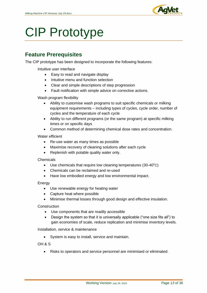
CIP Prototype
Feature Prerequisites
The CIP prototype has been designed to incorporate the following features:
Intuitive user interface
Easy to read and navigate display
Intuitive menu and function selection
Clear and simple descriptions of step progression
Fault notification with simple advice on corrective actions.
Wash program flexibility
Ability to customise wash programs to suit specific chemicals or milking
equipment requirements – including types of cycles, cycle order, number of
cycles and the temperature of each cycle
Ability to run different programs (or the same program) at specific milking
times or on specific days
Common method of determining chemical dose rates and concentration.
Water efficient
Re-use water as many times as possible
Maximise recovery of cleaning solutions after each cycle
Replenish with potable quality water only.
Chemicals
Use chemicals that require low cleaning temperatures (30-40oC)
Chemicals can be reclaimed and re-used
Have low embodied energy and low environmental impact.
Energy
Use renewable energy for heating water
Capture heat where possible
Minimise thermal losses through good design and effective insulation.
Construction
Use components that are readily accessible
Design the system so that it is universally applicable (“one size fits all”) to
gain economies of scale, reduce replication and minimise inventory levels.
Installation, service & maintenance
System is easy to install, service and maintain.
OH & S
Risks to operators and service personnel are minimised or eliminated.

Milking Machine CIP Almanac July 29.docx
Working Version July 29, 2010 Page 14 of 36
Design
The following schematic diagrams detail the layout of the various components of the
prototype CIP system. It is important to note that additional components were included in
the design to accommodate flexibility and to conduct research.
Dosing & Filling
Design particulars
50mm SS pipes.
Valves to be the same size as the pipes – 50mm.
Valves to be installed as close as possible to an intersection to ensure proper
drainage and minimise cross-contamination of liquids.
Valves used on prototype are pneumatically operated and are normally
closed. The drainage valve (V4 normally open) is vacuum operated.
Slope direction of return line should fall towards the drain valve (V4).
Pipes can enter via the wall of the tanks rather than through the lid. This
allows easier access to the inside of the tank.
Each return pipe terminates approximately 1/3 from the top of the tank.
Dosing tubes are connected to a ss nipple on the relevant return line entering
the tank (downstream of the valve).
Fresh water flow rate should be capable of filling the tank within 10 minutes –
at least 60 l/min.
A common fresh water supply is used to economise on the number of valves.
Milking Machine CIP Almanac July 29.docx
Working Version July 29, 2010 Page 15 of 36
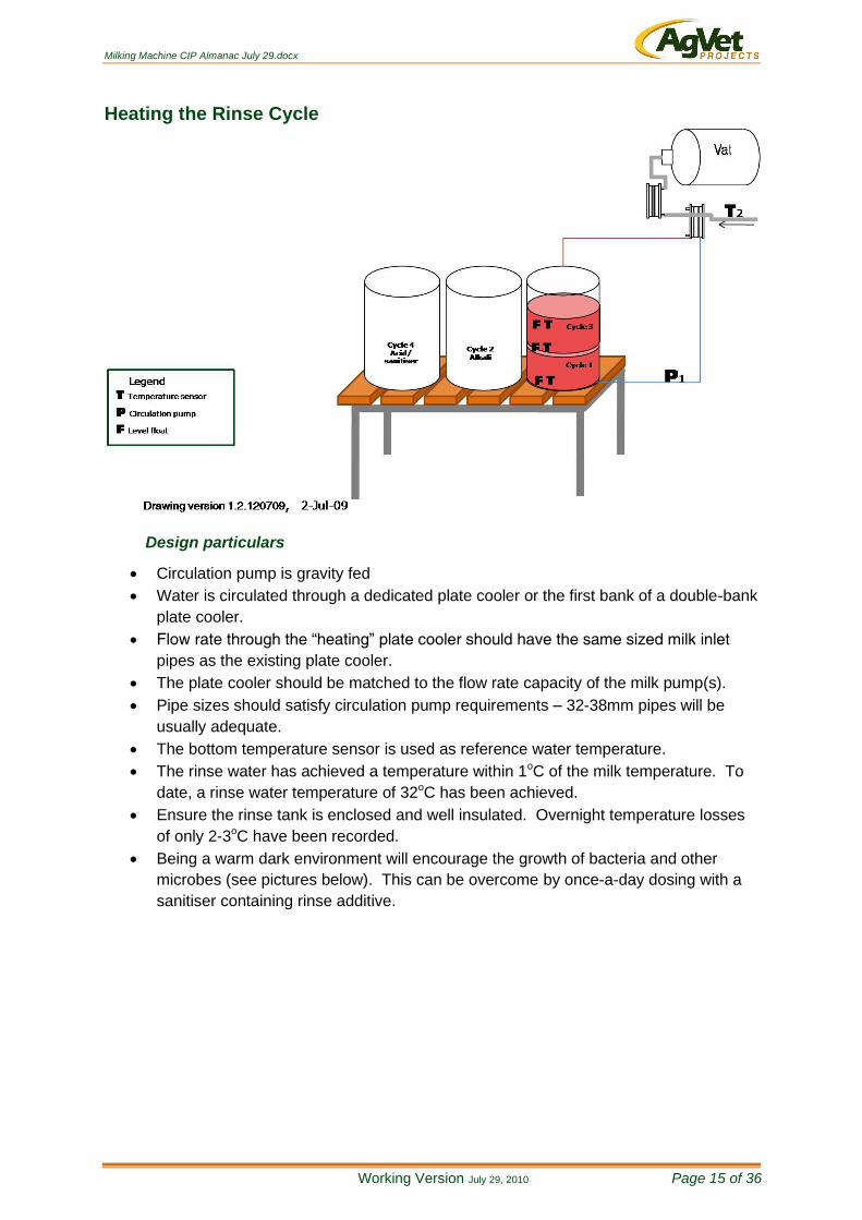
Heating the Rinse Cycle
Design particulars
Circulation pump is gravity fed
Water is circulated through a dedicated plate cooler or the first bank of a double-bank
plate cooler.
Flow rate through the “heating” plate cooler should have the same sized milk inlet
pipes as the existing plate cooler.
The plate cooler should be matched to the flow rate capacity of the milk pump(s).
Pipe sizes should satisfy circulation pump requirements – 32-38mm pipes will be
usually adequate.
The bottom temperature sensor is used as reference water temperature.
The rinse water has achieved a temperature within 1oC of the milk temperature. To
date, a rinse water temperature of 32oC has been achieved.
Ensure the rinse tank is enclosed and well insulated. Overnight temperature losses
of only 2-3oC have been recorded.
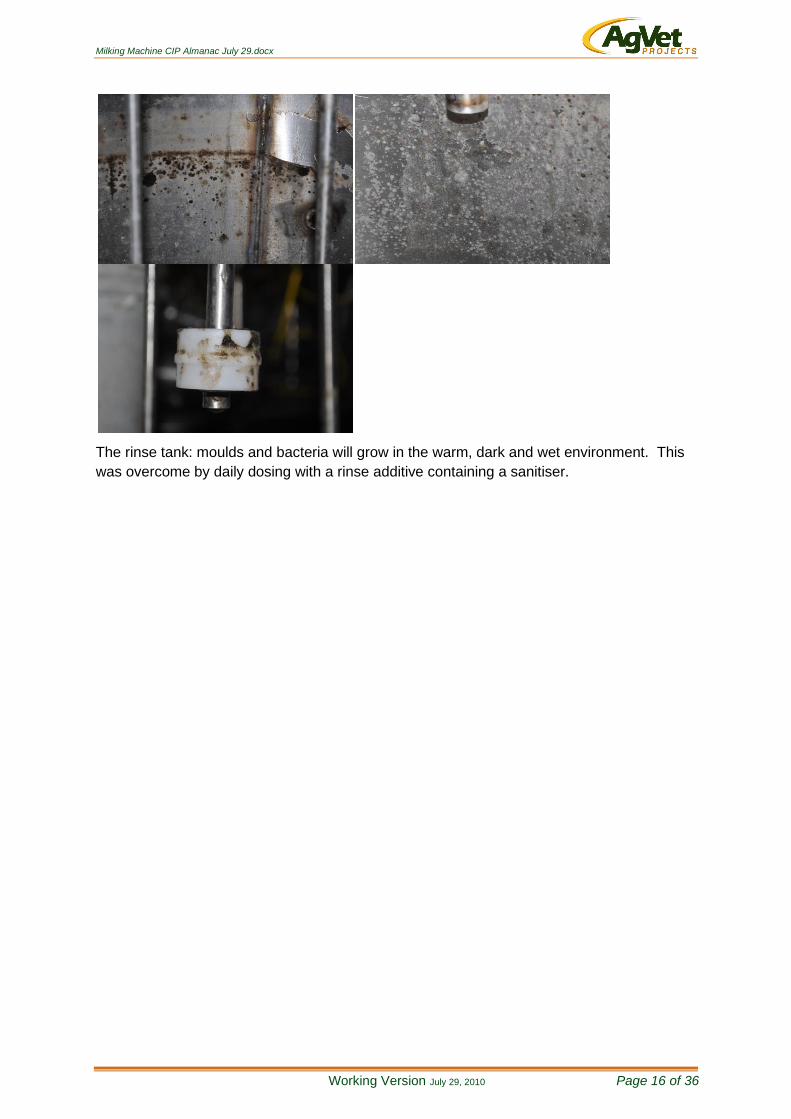
Being a warm dark environment will encourage the growth of bacteria and other
microbes (see pictures below). This can be overcome by once-a-day dosing with a
sanitiser containing rinse additive.
Milking Machine CIP Almanac July 29.docx
Working Version July 29, 2010 Page 16 of 36
The rinse tank: moulds and bacteria will grow in the warm, dark and wet environment. This
was overcome by daily dosing with a rinse additive containing a sanitiser.
Milking Machine CIP Almanac July 29.docx
Working Version July 29, 2010 Page 17 of 36
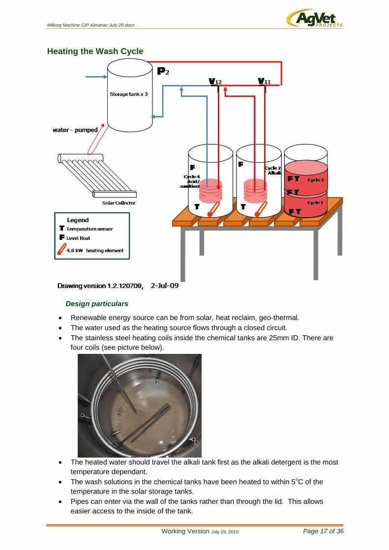
Heating the Wash Cycle
Design particulars
Renewable energy source can be from solar, heat reclaim, geo-thermal.
The water used as the heating source flows through a closed circuit.
The stainless steel heating coils inside the chemical tanks are 25mm ID. There are
four coils (see picture below).
The heated water should travel the alkali tank first as the alkali detergent is the most
temperature dependant.
The wash solutions in the chemical tanks have been heated to within 5oC of the
temperature in the solar storage tanks.
Pipes can enter via the wall of the tanks rather than through the lid. This allows
easier access to the inside of the tank.

Milking Machine CIP Almanac July 29.docx
Working Version July 29, 2010 Page 18 of 36
A 4.8kW heating element is installed at the base of the tank to provide supplementary
heating if required. It is a low watt density Incoly 825 element.
Wash Suction Line
Design particulars
50mm SS pipes.
Valves to be the same size as the pipes – 50mm.
Valves to be installed as close as possible to an intersection to ensure proper
drainage and minimise cross-contamination of liquids.
Valves used on prototype are pneumatically operated and are normally closed.
Line should fall towards the plant.
Pipes can enter via the wall of the tanks rather than through the lid. This allows
easier access to the inside of the tank.
Each return pipe terminates approximately 3/4 from the bottom of the tank.
The pipes entering the tanks should be higher than the conveyance pipe. These
pipes on the prototype have 180 degree bends to minimise the chance of cross-
contamination.
Milking Machine CIP Almanac July 29.docx
Working Version July 29, 2010 Page 19 of 36
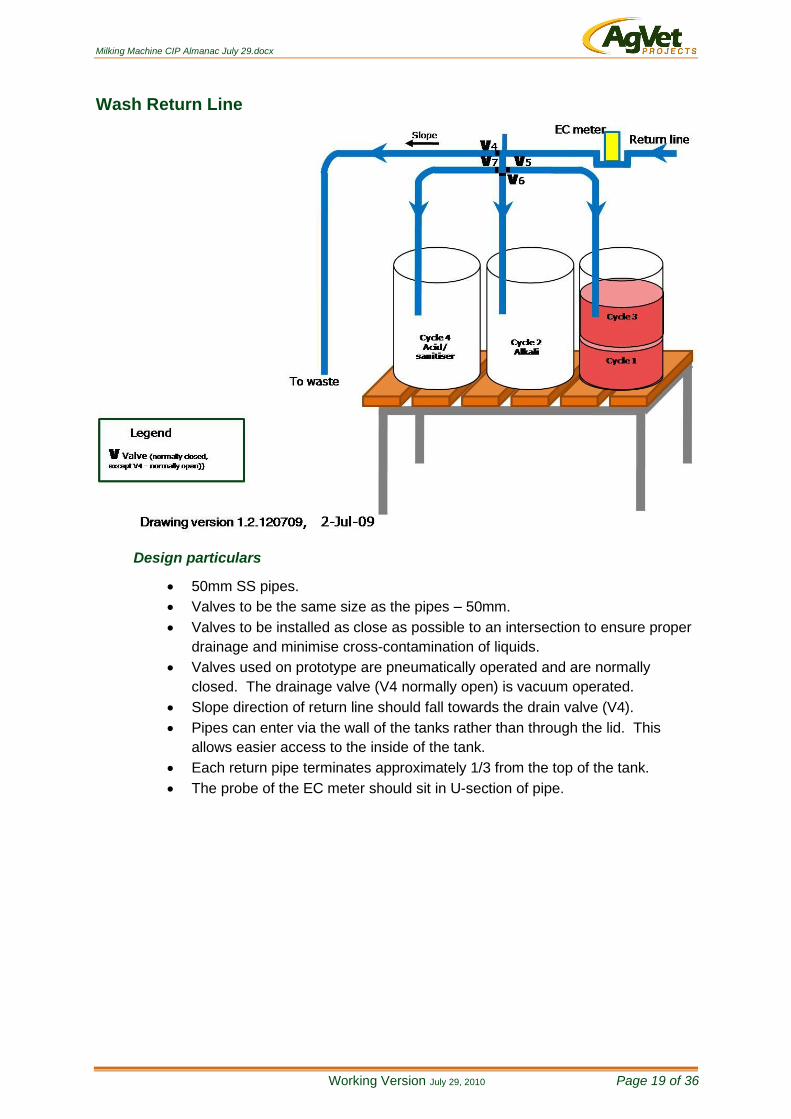
Wash Return Line
Design particulars
50mm SS pipes.
Valves to be the same size as the pipes – 50mm.
Valves to be installed as close as possible to an intersection to ensure proper
drainage and minimise cross-contamination of liquids.
Valves used on prototype are pneumatically operated and are normally
closed. The drainage valve (V4 normally open) is vacuum operated.
Slope direction of return line should fall towards the drain valve (V4).
Pipes can enter via the wall of the tanks rather than through the lid. This
allows easier access to the inside of the tank.
Each return pipe terminates approximately 1/3 from the top of the tank.
The probe of the EC meter should sit in U-section of pipe.
Milking Machine CIP Almanac July 29.docx
Working Version July 29, 2010 Page 20 of 36
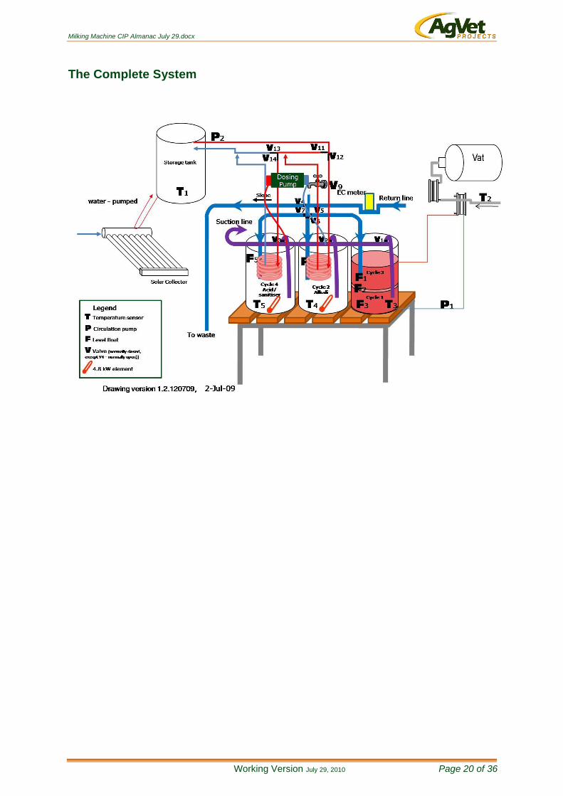
The Complete System

Milking Machine CIP Almanac July 29.docx
Working Version July 29, 2010 Page 21 of 36
The Rinse Tank
Milking Machine CIP Almanac July 29.docx
Working Version July 29, 2010 Page 22 of 36
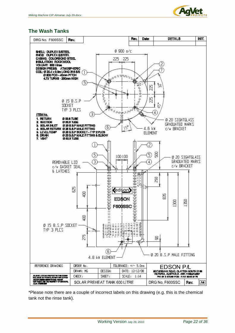
The Wash Tanks
*Please note there are a couple of incorrect labels on this drawing (e.g. this is the chemical
tank not the rinse tank).
Milking Machine CIP Almanac July 29.docx
Working Version July 29, 2010 Page 23 of 36
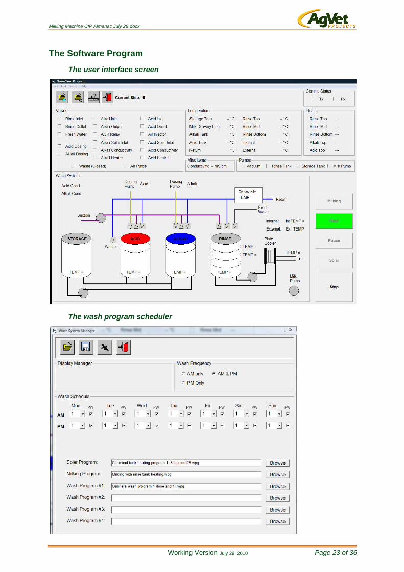
The Software Program
The user interface screen
The wash program scheduler
Milking Machine CIP Almanac July 29.docx
Working Version July 29, 2010 Page 24 of 36
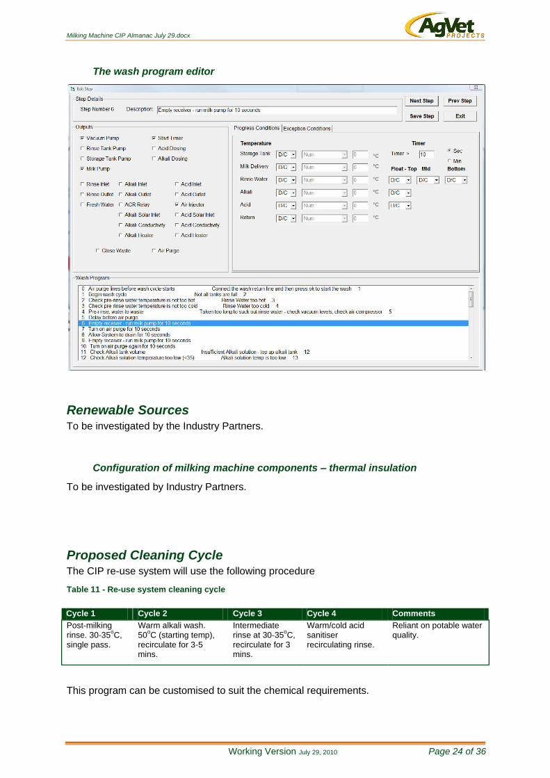
The wash program editor
Renewable Sources To be investigated by the Industry Partners.
Configuration of milking machine components – thermal insulation
To be investigated by Industry Partners.
Proposed Cleaning Cycle The CIP re-use system will use the following procedure
Table 11 - Re-use system cleaning cycle
This program can be customised to suit the chemical requirements.
Cycle 1 Cycle 2 Cycle 3 Cycle 4 Comments
Post-milking rinse. 30-35
oC,
single pass.
Warm alkali wash. 50
oC (starting temp),
recirculate for 3-5 mins.
Intermediate rinse at 30-35
oC,
recirculate for 3 mins.
Warm/cold acid sanitiser recirculating rinse.
Reliant on potable water quality.

Milking Machine CIP Almanac July 29.docx
Working Version July 29, 2010 Page 25 of 36
Valves, Senses & Switches
Floats & temperature sensors
Please refer to the appendix for details of the floats and temperature sensors used in the
prototype.
Solar inlet valve
3-way ss ball valve with pneumatic actuator. It has a T-port configuration with a
spring return. It operates on 12 V DC.
Tank inlet and outlet valves
Keystone 2” butterfly valves with pneumatic actuator, operating on 12 V DC.
References
Griffiths, M. W. 1993. Applications of bioluminescence in the dairy industry. J Dairy Sci.
76:3118-3125.
Romney AJD (ed.). 1990. CIP: Cleaning in Place, 2nd edition. The Society of Dairy
Technology, Cambridgeshire.
Vilar MJ, Rodríguez-Otero JL, Diéguez FJ, Sanjuán ML, Yus E. (2008) Application of ATP
bioluminescence for evaluation of surface cleanliness of milking equipment. Int J Food
Microbiol. May 2. [Epub ahead of print]
FINAL REPORT

Milking Machine CIP Almanac July 29.docx
Working Version July 29, 2010 Page 26 of 36
Appendix
Program Specifications & Description
Title: Project Description. - CONFIDENTIAL -
© Copyright Creative Product Design 2008
Page 26 This document and the information which it contains is the property of Creative Product Design Pty. Ltd.
and may only be used for the purpose for which it is provided.
GREEN CLEANING
WASH SYSTEM
- PROGRAM DESCRIPTION

Milking Machine CIP Almanac July 29.docx
Working Version July 29, 2010 Page 27 of 36
Preface
This document details various technical aspects of the AgVet GreenClean Wash System. It
is intended for use by qualified engineering professionals for servicing and post-design
engineering, therefore considerable knowledge of the various systems is assumed.
Milking Machine CIP Almanac July 29.docx
Working Version July 29, 2010 Page 28 of 36
Abbreviations
ADC Analogue to Digital Converter (MCU Module).
1WB 1-Wire Bus.
CPU Central Processing Unit.
CPD Creative Product Design.
I/O Input and/or Output.
LCD Liquid Crystal Display.
PC Personal Computer.
PWM Pulse Width Modulation.
WDT Watchdog Timer (MCU Module).
Notes
Unless indicated otherwise, signals are active-High. Where a signal is labelled with /(signal
name), that signal is to be considered active-Low.
‘High’ refers to a logical ‘1’.
‘Low’ refers to a logical ‘0’.
Universal logic notation is used throughout this document. It describes the state of a signal
as either ‘asserted’ or ‘de-asserted’ and is independent of whether that signal is active-High
or active-Low. Hence an active-Low signal that is asserted is ‘Low’ or logical 0, whereas an
active-High signal that is asserted is ‘High’ or logical 1.
Signal labels are shown in Bold throughout this document to differentiate from component or
pin names.
Milking Machine CIP Almanac July 29.docx
Working Version July 29, 2010 Page 29 of 36
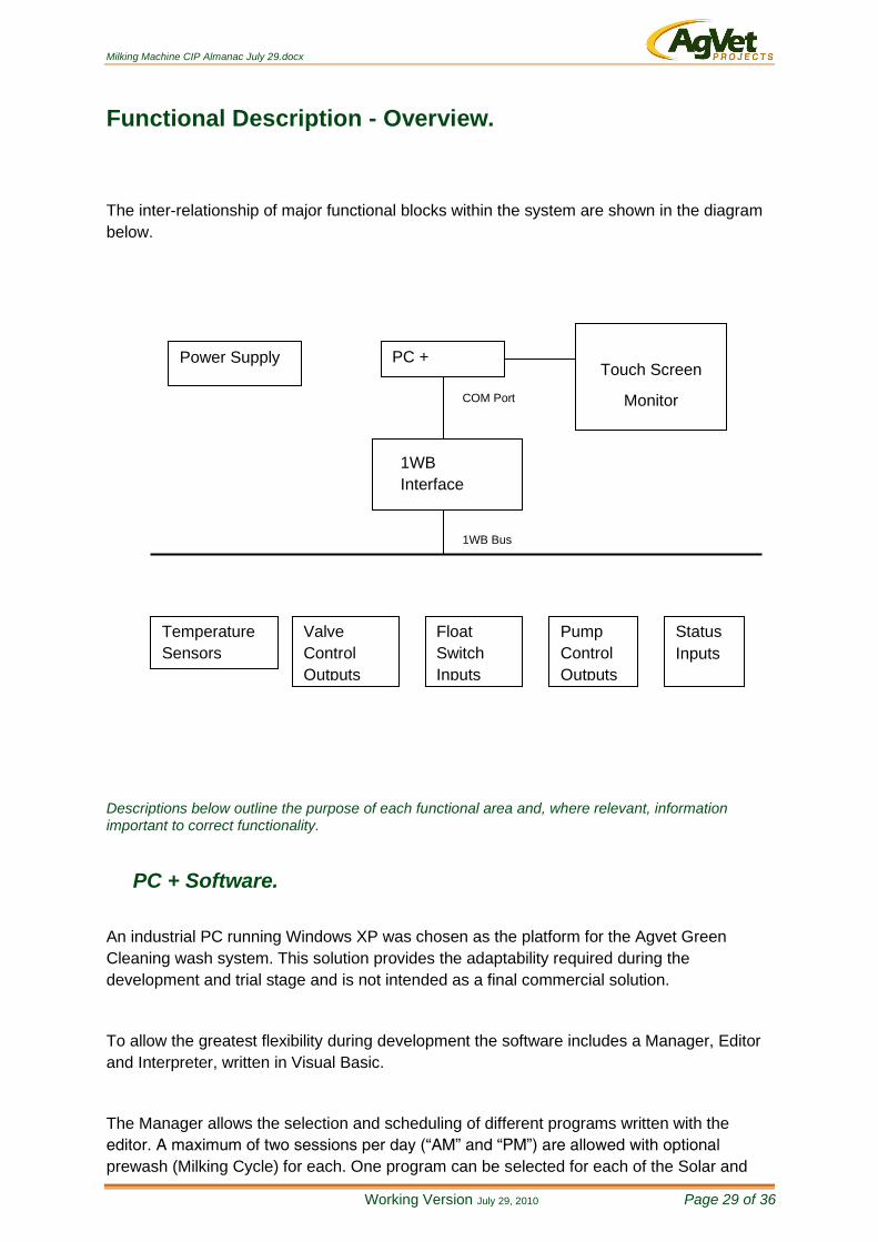
Functional Description - Overview.
The inter-relationship of major functional blocks within the system are shown in the diagram
below.
Descriptions below outline the purpose of each functional area and, where relevant, information important to correct functionality.
PC + Software.
An industrial PC running Windows XP was chosen as the platform for the Agvet Green
Cleaning wash system. This solution provides the adaptability required during the
development and trial stage and is not intended as a final commercial solution.
To allow the greatest flexibility during development the software includes a Manager, Editor
and Interpreter, written in Visual Basic.
The Manager allows the selection and scheduling of different programs written with the
editor. A maximum of two sessions per day (“AM” and “PM”) are allowed with optional
prewash (Milking Cycle) for each. One program can be selected for each of the Solar and
1WB Bus
PC +
Software
1WB
Interface
(EDS HA7E)
COM Port
Temperature
Sensors
Valve
Control
Outputs
Power Supply
Float
Switch
Inputs
Pump
Control
Outputs
Status
Inputs
Touch Screen
Monitor

Milking Machine CIP Almanac July 29.docx
Working Version July 29, 2010 Page 30 of 36
Milking cycles and up to four different wash programs can be specified and selected over the
7 day schedule..
The Editor enables specific functionality to be realised for each cycle, namely Milking,
Washing and Solar and for this functionality to be altered as required. Each cycle consists of
multiple steps that define the outputs that are enabled, and the conditions to progress to the
next step, plus exception conditions for alternative progress. The conditions are made up of
the various temperature and float switch inputs, plus timers.
The Interpreter decodes the program and provides the interface to and control of the pumps,
valves, sensors and switch inputs. The current status of the system is displayed using a
pictogram and tabulated data.
Other functions implemented include data logging of all inputs and automated dosing
calculations based on the specific characteristics of the chemicals being used. Chemical
characteristics can be altered to suit different chemicals as required.
Touch Screen.
The operator intereface is a 17” 1280X1024 touchscreen driven by the industrial PC under
the control of Windows XP.
1WB Interface (EDS HA7E).
To further allow flexibility in the system setup, a One-wire bus (1WB) network of sensors was
utilised. The 1WB is a proprietary network that can easily be expanded. A 1WB to RS232
convertor, the EDS HA7E, was selected to enable easy setup and configuration of the 1WB
through the PC.
Temperature Sensor.
The temperature sensor is a 1WB device with digital output and CRC error checking.
Float Switch Input.
The float switch input is a 1WB digital I/O device. It has been interfaced with a reed switch
and magnetic float to indicate fluid level.

Milking Machine CIP Almanac July 29.docx
Working Version July 29, 2010 Page 31 of 36
Control Outputs.
The control outputs consist of a 1WB digital I/O device connected to a relay to provide both
NO and NC dry contacts.
Analogue Input.
The analogue input is made up of a 1WB interfaced Analogue to Digital Converter with 4-
20mA loop inputs. The loop inputs are connected to a Jumo CTI-500 Conductivity and
Temperature sensor, which takes readings from the return water.
Power Supply.
The Power supply consists of a wide-input switch mode power supply to allow operation over
a wide and potentially varying input voltage, plus battery backup for brown and black-out
power failures.
Milking Machine CIP Almanac July 29.docx
Working Version July 29, 2010 Page 32 of 36
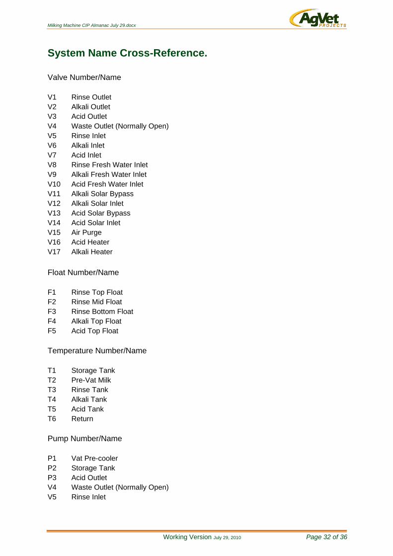
System Name Cross-Reference.
Valve Number/Name
V1 Rinse Outlet
V2 Alkali Outlet
V3 Acid Outlet
V4 Waste Outlet (Normally Open)
V5 Rinse Inlet
V6 Alkali Inlet
V7 Acid Inlet
V8 Rinse Fresh Water Inlet
V9 Alkali Fresh Water Inlet
V10 Acid Fresh Water Inlet
V11 Alkali Solar Bypass
V12 Alkali Solar Inlet
V13 Acid Solar Bypass
V14 Acid Solar Inlet
V15 Air Purge
V16 Acid Heater
V17 Alkali Heater
Float Number/Name
F1 Rinse Top Float
F2 Rinse Mid Float
F3 Rinse Bottom Float
F4 Alkali Top Float
F5 Acid Top Float
Temperature Number/Name
T1 Storage Tank
T2 Pre-Vat Milk
T3 Rinse Tank
T4 Alkali Tank
T5 Acid Tank
T6 Return
Pump Number/Name
P1 Vat Pre-cooler
P2 Storage Tank
P3 Acid Outlet
V4 Waste Outlet (Normally Open)
V5 Rinse Inlet
Milking Machine CIP Almanac July 29.docx Working Version February 9, 2010 Page 33 of 36
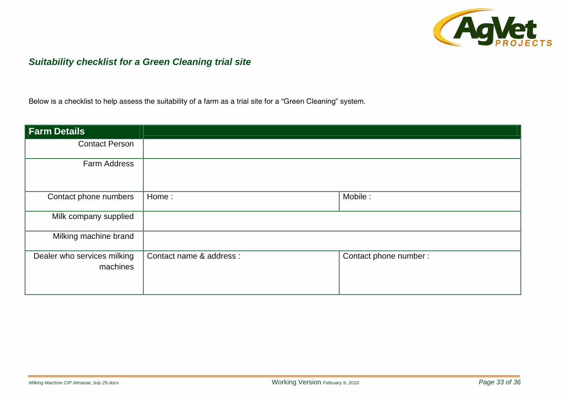
Suitability checklist for a Green Cleaning trial site
Below is a checklist to help assess the suitability of a farm as a trial site for a “Green Cleaning” system.
Farm Details
Contact Person
Farm Address
Contact phone numbers Home : Mobile :
Milk company supplied
Milking machine brand
Dealer who services milking
machines
Contact name & address :
Contact phone number :
Milking Machine CIP Almanac July 29.docx
Milking Machine CIP Almanac July 29.docx Working Version July 29, 2010 Page 34 of 36
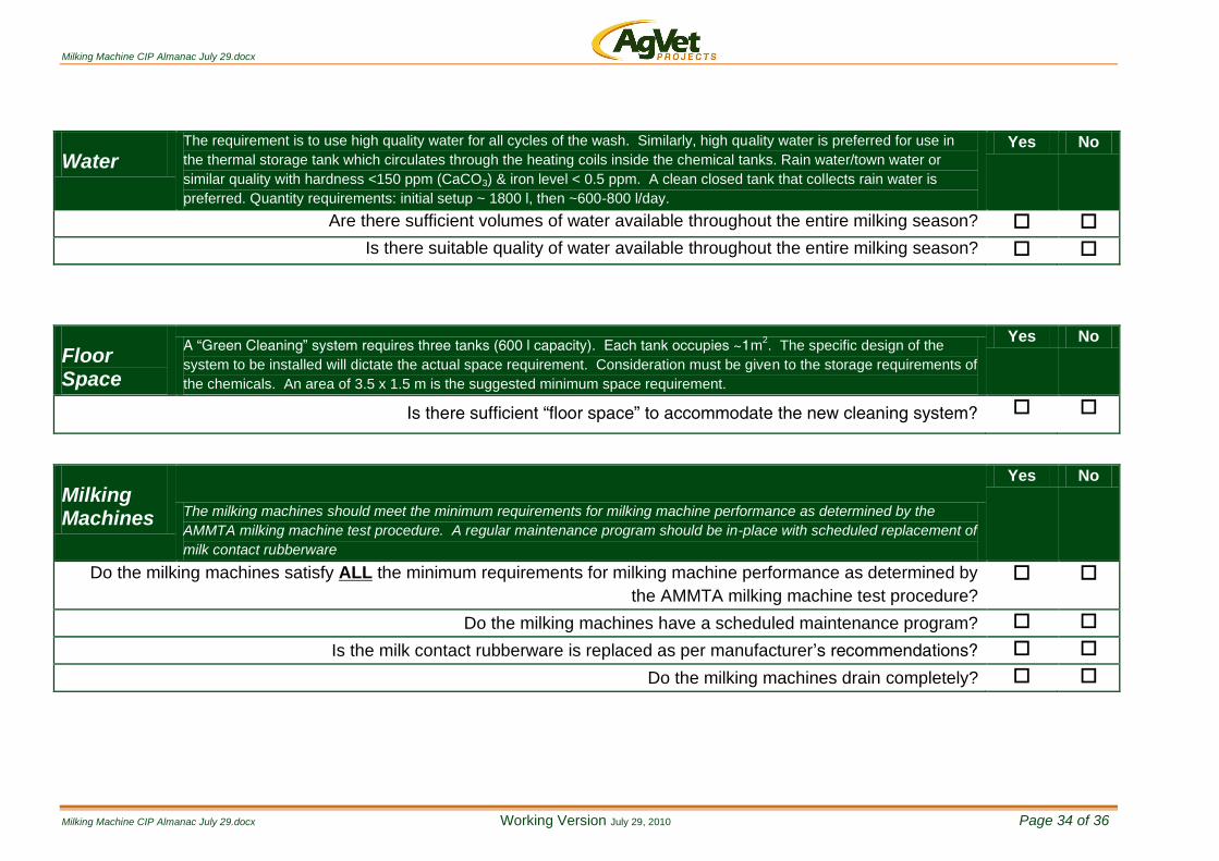
Water The requirement is to use high quality water for all cycles of the wash. Similarly, high quality water is preferred for use in
the thermal storage tank which circulates through the heating coils inside the chemical tanks. Rain water/town water or
similar quality with hardness <150 ppm (CaCO3) & iron level < 0.5 ppm. A clean closed tank that collects rain water is
preferred. Quantity requirements: initial setup ~ 1800 l, then ~600-800 l/day.
Yes No
Are there sufficient volumes of water available throughout the entire milking season?
Is there suitable quality of water available throughout the entire milking season?
Floor Space
A “Green Cleaning” system requires three tanks (600 l capacity). Each tank occupies ~1m2. The specific design of the
system to be installed will dictate the actual space requirement. Consideration must be given to the storage requirements of
the chemicals. An area of 3.5 x 1.5 m is the suggested minimum space requirement.
Yes No
Is there sufficient “floor space” to accommodate the new cleaning system?
Milking Machines The milking machines should meet the minimum requirements for milking machine performance as determined by the
AMMTA milking machine test procedure. A regular maintenance program should be in-place with scheduled replacement of
milk contact rubberware
Yes No
Do the milking machines satisfy ALL the minimum requirements for milking machine performance as determined by
the AMMTA milking machine test procedure?
Do the milking machines have a scheduled maintenance program?
Is the milk contact rubberware is replaced as per manufacturer’s recommendations?
Do the milking machines drain completely?

Milking Machine CIP Almanac July 29.docx
Milking Machine CIP Almanac July 29.docx Working Version July 29, 2010 Page 35 of 36
Renewable Energy Sources
The most likely forms of renewable energy will be solar or heat reclaim. Whilst products such as heat pumps can be used,
they are grid connected and the energy supply is from non-renewable sources. Likewise, adaptation of existing HWS could
also be considered but again, their energy source is typically non-renewable.
Yes No
Solar Hot Water Systems
Solar hot water systems are better suited to some geographical areas than others. Having access to an unobstructed north-facing roof for the solar
collectors is paramount. Consultation with a solar hot water specialist to determine size & performance characteristics is necessary.
Is the orientation for solar hot water service correct?
Is there sufficient “floor space” to accommodate the water storage tank(s)?
Heat Reclaim Systems
If a heat reclaim system on the milk tank refrigeration unit is a considered possibility/option then a farm with a minimum daily production of ~7,000 l is
preferred. On smaller farms a year-round or split calving farm is best suited to achieving the minimum daily production volumes. It is important to
note that many factors are considered when calculating the minimum milk production requirements. Such factors include:
Type & performance of the pre-cooling system;
Type of refrigeration system (different refrigerant gases have different evaporative temperatures);
Type and performance of the heat reclaim system.
Volume of chemical wash solutions to be heated.
Temperatures to which each chemical wash solution must be heated.
How the rinse water will be heated.
Is there sufficient “floor space” to accommodate the heat reclaim system?
Is the heat reclaim system close enough to the chemical wash tanks to minimise heat losses?
Can the heat reclaim system and the chemical wash system be connected without pipework causing obstructions?

Milking Machine CIP Almanac July 29.docx
Milking Machine CIP Almanac July 29.docx Working Version July 29, 2010 Page 36 of 36
Milk Quality
The farm should be able to demonstrate a record of good (premium) milk quality. The quality parameters should include
BMCCs, Temperature, TPC/Bactoscan & thermodurics.
Yes No
Are all parameters for good milk quality met?
Are the results consistently good throughout the year?
OH & S The farm will be a workplace & demonstration site and so a safe environment should exist at all times. A risk assessment
should be undertaken and any identified risks mitigated.
Yes No
Does the site provide a safe workplace?
Is the site safe?
Have identified risks been mitigated?
For further information contact
Gabriel Hakim
m: 0407 358 399
f: 03 5626 1141 (Ellinbank office)
f: 03 5623 5583 (Warragul office)