Embed Size (px)
Citation preview
�
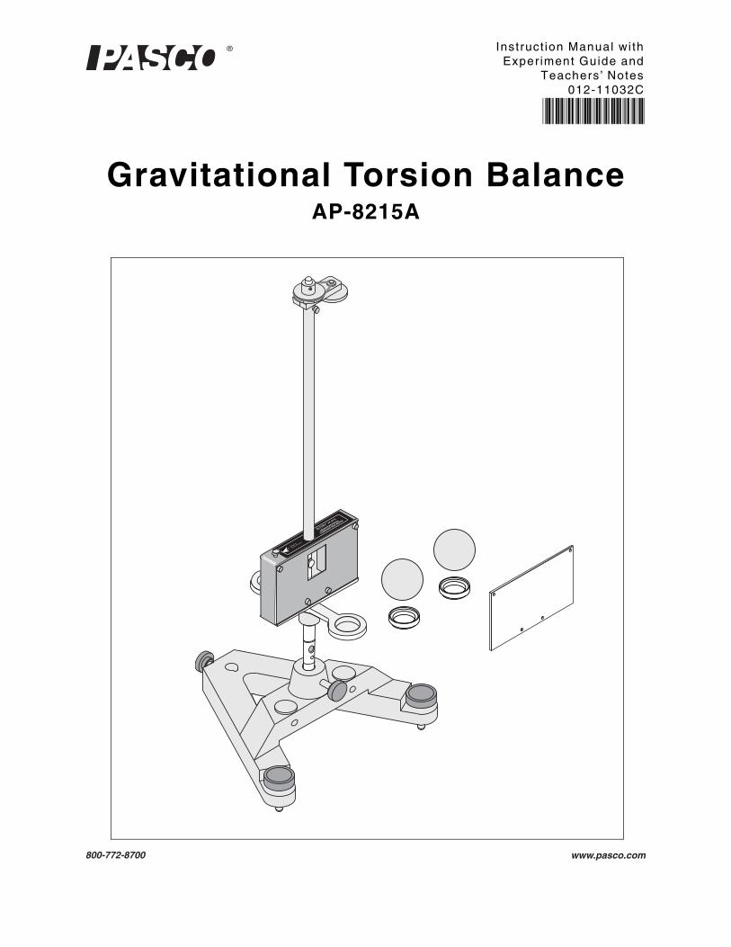
Gravitational Torsion BalanceAP-8215A
Instruct ion Manual wi thExper iment Guide and
Teachers’ Notes012-11032C
*012-11032*
Attach to
EarthGround.
GRAVITATIONAL
TORSION BALANCE
AP-8215

Note: To avoid breaking the torsion ribbon, the locking mechanism must be fully raised on both sides when moving or transporting the Gravitational Torsion Balance.
Note: Save the packing material from the interior of the box, and re-install this material when moving or transporting the Gravitational Torsion Balance.
Gravi tat ional Torsion Balance Table of Contents
i
Section Page
Copyright, Warranty and Equipment Return . . . . . . . . . . . . . . . . . . . . . . . . . . . . . . . . . . ii
Introduction . . . . . . . . . . . . . . . . . . . . . . . . . . . . . . . . . . . . . . . . . . . . . . . . . . . . . . . . . . . 1
Equipment . . . . . . . . . . . . . . . . . . . . . . . . . . . . . . . . . . . . . . . . . . . . . . . . . . . . . . . . . . . . 2
Equipment Parameters . . . . . . . . . . . . . . . . . . . . . . . . . . . . . . . . . . . . . . . . . . . . . . . . . . . 3
Equipment Setup . . . . . . . . . . . . . . . . . . . . . . . . . . . . . . . . . . . . . . . . . . . . . . . . . . . . . . . 3
Initial Setup. . . . . . . . . . . . . . . . . . . . . . . . . . . . . . . . . . . . . . . . . . . . . . . . . . . . . . . . . . . . . 3
Leveling the Gravitational Torsion Balance . . . . . . . . . . . . . . . . . . . . . . . . . . . . . . . . . . . . 4
Vertical Adjustment of the Pendulum . . . . . . . . . . . . . . . . . . . . . . . . . . . . . . . . . . . . . . . . . 4
Rotational Alignment of the Pendulum Bob Arms (Zeroing). . . . . . . . . . . . . . . . . . . . . . . . 5
Setting up for the Experiment . . . . . . . . . . . . . . . . . . . . . . . . . . . . . . . . . . . . . . . . . . . . . . . 6
Measuring the Gravitational Constant . . . . . . . . . . . . . . . . . . . . . . . . . . . . . . . . . . . . . . . 7
Overview of the Experiment . . . . . . . . . . . . . . . . . . . . . . . . . . . . . . . . . . . . . . . . . . . . . . . . 7
Method I: Measurement by Final Deflection . . . . . . . . . . . . . . . . . . . . . . . . . . . . . . . . . . 7
Theory . . . . . . . . . . . . . . . . . . . . . . . . . . . . . . . . . . . . . . . . . . . . . . . . . . . . . . . . . . . . . . . . 7
Procedure . . . . . . . . . . . . . . . . . . . . . . . . . . . . . . . . . . . . . . . . . . . . . . . . . . . . . . . . . . . . . 9
Analysis . . . . . . . . . . . . . . . . . . . . . . . . . . . . . . . . . . . . . . . . . . . . . . . . . . . . . . . . . . . . . . 10
Method II: Measurement by Equilibrium Positions. . . . . . . . . . . . . . . . . . . . . . . . . . . . . 11
Theory . . . . . . . . . . . . . . . . . . . . . . . . . . . . . . . . . . . . . . . . . . . . . . . . . . . . . . . . . . . . . . . 11
Procedure . . . . . . . . . . . . . . . . . . . . . . . . . . . . . . . . . . . . . . . . . . . . . . . . . . . . . . . . . . . . 11
Analysis . . . . . . . . . . . . . . . . . . . . . . . . . . . . . . . . . . . . . . . . . . . . . . . . . . . . . . . . . . . . . . 11
Method III: Measurement by Acceleration . . . . . . . . . . . . . . . . . . . . . . . . . . . . . . . . . . . 12
Theory . . . . . . . . . . . . . . . . . . . . . . . . . . . . . . . . . . . . . . . . . . . . . . . . . . . . . . . . . . . . . . . 12
Procedure. . . . . . . . . . . . . . . . . . . . . . . . . . . . . . . . . . . . . . . . . . . . . . . . . . . . . . . . . . . . . 13
Analysis . . . . . . . . . . . . . . . . . . . . . . . . . . . . . . . . . . . . . . . . . . . . . . . . . . . . . . . . . . . . . . 13
Maintenance . . . . . . . . . . . . . . . . . . . . . . . . . . . . . . . . . . . . . . . . . . . . . . . . . . . . . . . . . 14
Transporting and Storing . . . . . . . . . . . . . . . . . . . . . . . . . . . . . . . . . . . . . . . . . . . . . . . . 15
Safety Precaution. . . . . . . . . . . . . . . . . . . . . . . . . . . . . . . . . . . . . . . . . . . . . . . . . . . . . . 15
Technical Support . . . . . . . . . . . . . . . . . . . . . . . . . . . . . . . . . . . . . . . . . . . . . . . . . . . . . 15
�
Gravi tat ional Torsion Balance Copyr ight , Warranty, and Equipment Return
ii
Copyright, Warranty, and Equipment ReturnPlease—Feel free to duplicate this manual subject to the copyright restrictions below.
Copyright Notice
The PASCO scientific 012-11032C Gravitational Torsion Balance manual is copyrighted and all rights reserved. However, permission is granted to non-profit educational institutions for reproduction of any part of the manual providing the reproductions are used only for their laboratories and are not sold for profit. Reproduction under any other circumstances, without the written consent of PASCO scientific, is prohibited.
Limited Warranty
PASCO scientific warrants the product to be free from defects in materials and workmanship for a period of one year from the date of shipment to the customer. PASCO will repair or replace at its option any part of the product which is deemed to be defective in material or workmanship. The warranty does not cover damage to the product caused by abuse or improper use. Determination of whether a product failure is the result of a manufacturing defect or improper use by the customer shall be made solely by PASCO scientific. Responsibility for the return of equipment for warranty repair belongs to the customer. Equipment must be properly packed to prevent dam-age and shipped postage or freight prepaid. (Damage caused by improper packing of the equipment for return shipment will not be covered by the warranty.) Shipping costs for returning the equipment after repair will be paid by PASCO scientific.
Equipment Return
Should the product have to be returned to PASCO scientific for any reason, notify PASCO scientific by letter, phone, or fax BEFORE returning the product. Upon notification, the return authorization and shipping instruc-tions will be promptly issued.
• NOTE: NO EQUIPMENT WILL BE ACCEPTED FOR RETURN WITHOUT AN AUTHORIZATION FROM PASCO.
When returning equipment for repair, the units must be packed properly. Carriers will not accept responsibility for damage caused by improper packing. To be certain the unit will not be damaged in shipment, observe the fol-lowing rules:
• The packing carton must be strong enough for the item shipped.
• Make certain there are at least two inches of packing material between any point on the apparatus and the inside walls of the carton.
• Make certain that the packing material cannot shift in the box or become compressed, allowing theinstrument come in contact with the packing carton.
Address: PASCO scientific10101 Foothills Blvd.Roseville, CA 95747-7100
Phone:(916) 786-3800 (worldwide) or 800-772-8700 (US)web:www.pasco.com
�
Model No. AP-8215A Introduct ion
1012-11032C
Introduction
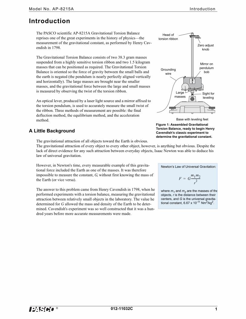
The PASCO scientific AP-8215A Gravitational Torsion Balance reprises one of the great experiments in the history of physics—the measurement of the gravitational constant, as performed by Henry Cav-endish in 1798.
The Gravitational Torsion Balance consists of two 38.3 gram masses suspended from a highly sensitive torsion ribbon and two 1.5 kilogram masses that can be positioned as required. The Gravitational Torsion Balance is oriented so the force of gravity between the small balls and the earth is negated (the pendulum is nearly perfectly aligned vertically and horizontally). The large masses are brought near the smaller masses, and the gravitational force between the large and small masses is measured by observing the twist of the torsion ribbon.
An optical lever, produced by a laser light source and a mirror affixed to the torsion pendulum, is used to accurately measure the small twist of the ribbon. Three methods of measurement are possible: the final deflection method, the equilibrium method, and the acceleration method.
A Little Background
The gravitational attraction of all objects toward the Earth is obvious. The gravitational attraction of every object to every other object, however, is anything but obvious. Despite the lack of direct evidence for any such attraction between everyday objects, Isaac Newton was able to deduce his law of universal gravitation.
However, in Newton's time, every measurable example of this gravita-tional force included the Earth as one of the masses. It was therefore impossible to measure the constant, G, without first knowing the mass of the Earth (or vice versa).
The answer to this problem came from Henry Cavendish in 1798, when he performed experiments with a torsion balance, measuring the gravitational attraction between relatively small objects in the laboratory. The value he determined for G allowed the mass and density of the Earth to be deter-mined. Cavendish's experiment was so well constructed that it was a hun-dred years before more accurate measurements were made.
Base with leveling feet
Large masses
Sight for leveling
Grounding wire
Head of torsion ribbon
Zero adjust knob
Mirror on pendulum
bob
Figure 1: Assembled Gravitational Torsion Balance, ready to begin Henry Cavendish’s classic experiment to determine the gravitational constant.
Newton’s Law of Universal Gravitation:
where m1 and m2 are the masses of theobjects, r is the distance between their centers, and G is the universal gravita-tional constant, 6.67 x 10⁻¹¹ Nm2/kg2.
F Gm1m2
r2
--------------=
�
Gravi tat ional Torsion Balance Equipment
2 012-11032C
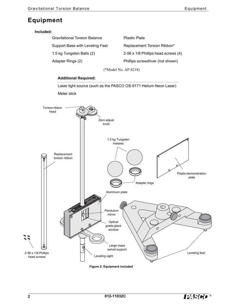
Equipment
Included:
(*Model No. AP-8218)
Gravitational Torsion Balance Plastic Plate
Support Base with Leveling Feet Replacement Torsion Ribbon*
1.5 kg Tungsten Balls (2) 2-56 x 1/8 Phillips head screws (4)
Adapter Rings (2) Phillips screwdriver (not shown)
Additional Required:
Laser light source (such as the PASCO OS-9171 Helium-Neon Laser)
Meter stick
Attach to
EarthGround.
GRAVITATIONAL
TORSION BALANCE
AP-8215
1.5 kg Tungsten masses
Adapter rings
Plastic demonstration plate
Replacement torsion ribbon
Zero adjust knob
Torsion ribbon head
Aluminum plate
Leveling feet
Pendulum mirror
Optical grade glass
window
Large mass swivel support
Leveling sight2-56 x 1/8 Phillips
head screws
Figure 2: Equipment included
�
Model No. AP-8215A Equipment Setup
3012-11032C
Equipment Parameters
• Small tungsten balls
Mass: 38.3 g ±0.2 g (m2)
Radius: 8.19 mmDistance from ball center to torsion axis: d = 50.0 mm
• Large tungsten balls
Mass: 1500 ±10 g (m1)
Radius: 27.6 mm
• Distance from the center of the large ball to the center of mass of the small ball when the large ball is against the aluminum plate and the small ball is in the center position within the case: b = 42.2 mm. (Note: Tolerances may vary depending on the accuracy of the horizontal alignment of the pendulum.)
• Distance from the surface of the mirror to the outer surface of the glass window: 11.4 mm
• Torsion Ribbon
Material: Beryllium CopperLength: approximately 260 mmCross-section: 0.017 by 0.150 mm
Equipment Setup
Initial Setup
1. Place the support base on a flat, stable table that is located such that the Gravitational Torsion Balance will be at least 5 meters away from a wall or screen.
Note: For best results, use a very sturdy table, such as an optics table.
2. Carefully remove the Gravitational Torsion Balance from the box, and secure it in the base.
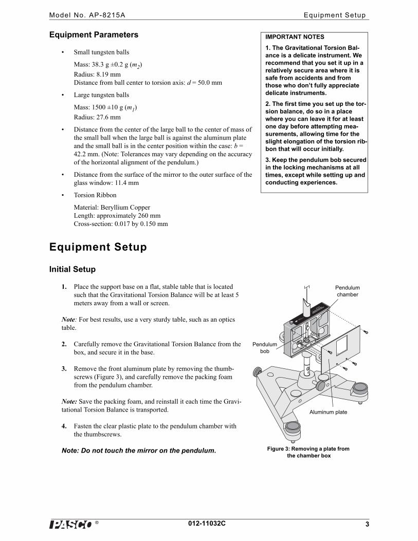
3. Remove the front aluminum plate by removing the thumb-screws (Figure 3), and carefully remove the packing foam from the pendulum chamber.
Note: Save the packing foam, and reinstall it each time the Gravi-tational Torsion Balance is transported.
4. Fasten the clear plastic plate to the pendulum chamber with the thumbscrews.
Note: Do not touch the mirror on the pendulum.
IMPORTANT NOTES
1. The Gravitational Torsion Bal-ance is a delicate instrument. We recommend that you set it up in a relatively secure area where it is safe from accidents and from those who don’t fully appreciate delicate instruments.
2. The first time you set up the tor-sion balance, do so in a place where you can leave it for at least one day before attempting mea-surements, allowing time for the slight elongation of the torsion rib-bon that will occur initially.
3. Keep the pendulum bob secured in the locking mechanisms at all times, except while setting up and conducting experiences.
Attach to
EarthGround.
GRAVITATIONAL
TORSION BALANCE
AP-8215
Figure 3: Removing a plate from the chamber box
Aluminum plate
Pendulum chamber
Pendulum bob
�
Gravi tat ional Torsion Balance Equipment Setup
4 012-11032C
Leveling the Gravitational Torsion Balance
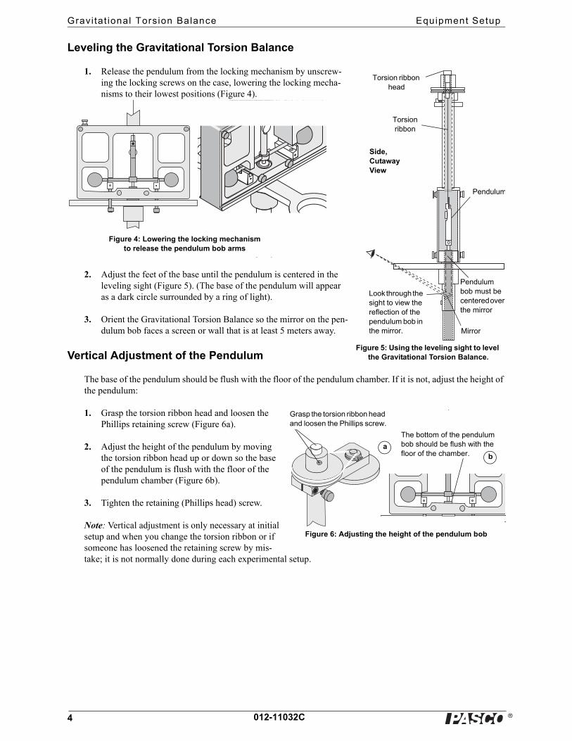
1. Release the pendulum from the locking mechanism by unscrew-ing the locking screws on the case, lowering the locking mecha-nisms to their lowest positions (Figure 4).
2. Adjust the feet of the base until the pendulum is centered in the leveling sight (Figure 5). (The base of the pendulum will appear as a dark circle surrounded by a ring of light).
3. Orient the Gravitational Torsion Balance so the mirror on the pen-dulum bob faces a screen or wall that is at least 5 meters away.
Vertical Adjustment of the Pendulum
The base of the pendulum should be flush with the floor of the pendulum chamber. If it is not, adjust the height of the pendulum:
1. Grasp the torsion ribbon head and loosen the Phillips retaining screw (Figure 6a).
2. Adjust the height of the pendulum by moving the torsion ribbon head up or down so the base of the pendulum is flush with the floor of the pendulum chamber (Figure 6b).
3. Tighten the retaining (Phillips head) screw.
Note: Vertical adjustment is only necessary at initial setup and when you change the torsion ribbon or if someone has loosened the retaining screw by mis-take; it is not normally done during each experimental setup.
Pendulum bob must be centered over the mirror
Mirror
Pendulum
Torsion ribbon
Torsion ribbon head
Look through the sight to view the reflection of the pendulum bob in the mirror.
Figure 5: Using the leveling sight to level the Gravitational Torsion Balance.
Side, Cutaway View
Attach to
EarthGround.
Figure 4: Lowering the locking mechanism to release the pendulum bob arms
Figure 6: Adjusting the height of the pendulum bob
The bottom of the pendulum bob should be flush with the floor of the chamber.
ab
Grasp the torsion ribbon head and loosen the Phillips screw.
�
Model No. AP-8215A Equipment Setup
5012-11032C
Rotational Alignment of the Pendulum Bob Arms (Zeroing)
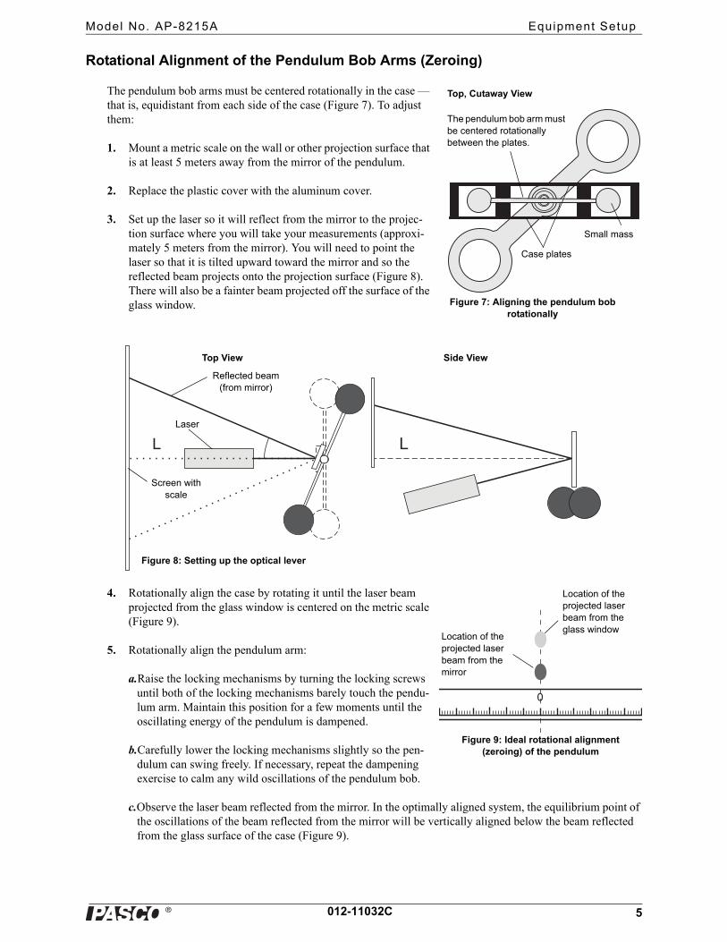
The pendulum bob arms must be centered rotationally in the case — that is, equidistant from each side of the case (Figure 7). To adjust them:
1. Mount a metric scale on the wall or other projection surface that is at least 5 meters away from the mirror of the pendulum.
2. Replace the plastic cover with the aluminum cover.
3. Set up the laser so it will reflect from the mirror to the projec-tion surface where you will take your measurements (approxi-mately 5 meters from the mirror). You will need to point the laser so that it is tilted upward toward the mirror and so the reflected beam projects onto the projection surface (Figure 8). There will also be a fainter beam projected off the surface of the glass window.
4. Rotationally align the case by rotating it until the laser beam projected from the glass window is centered on the metric scale (Figure 9).
5. Rotationally align the pendulum arm:
a.Raise the locking mechanisms by turning the locking screws until both of the locking mechanisms barely touch the pendu-lum arm. Maintain this position for a few moments until the oscillating energy of the pendulum is dampened.
b.Carefully lower the locking mechanisms slightly so the pen-dulum can swing freely. If necessary, repeat the dampening exercise to calm any wild oscillations of the pendulum bob.
c.Observe the laser beam reflected from the mirror. In the optimally aligned system, the equilibrium point of the oscillations of the beam reflected from the mirror will be vertically aligned below the beam reflected from the glass surface of the case (Figure 9).
Case plates
Small mass
The pendulum bob arm must be centered rotationally between the plates.
Figure 7: Aligning the pendulum bob rotationally
Top, Cutaway View
L L
Top View
Figure 8: Setting up the optical lever
Side View
Screen with scale
Laser
Reflected beam (from mirror)
0
Figure 9: Ideal rotational alignment (zeroing) of the pendulum
Location of the projected laser beam from the glass window
Location of the projected laser beam from the mirror
�
Gravi tat ional Torsion Balance Equipment Setup
6 012-11032C
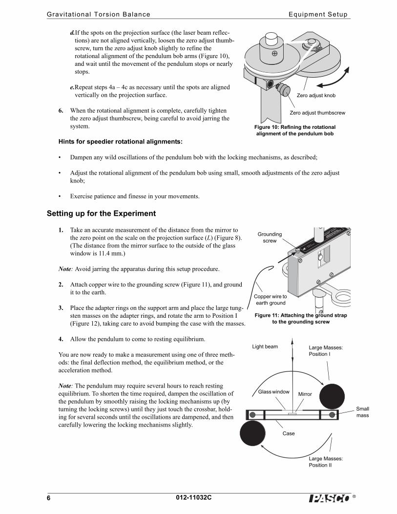
d.If the spots on the projection surface (the laser beam reflec-tions) are not aligned vertically, loosen the zero adjust thumb-screw, turn the zero adjust knob slightly to refine the rotational alignment of the pendulum bob arms (Figure 10), and wait until the movement of the pendulum stops or nearly stops.
e.Repeat steps 4a – 4c as necessary until the spots are aligned vertically on the projection surface.
6. When the rotational alignment is complete, carefully tighten the zero adjust thumbscrew, being careful to avoid jarring the system.
Hints for speedier rotational alignments:
• Dampen any wild oscillations of the pendulum bob with the locking mechanisms, as described;
• Adjust the rotational alignment of the pendulum bob using small, smooth adjustments of the zero adjust knob;
• Exercise patience and finesse in your movements.
Setting up for the Experiment
1. Take an accurate measurement of the distance from the mirror to the zero point on the scale on the projection surface (L) (Figure 8). (The distance from the mirror surface to the outside of the glass window is 11.4 mm.)
Note: Avoid jarring the apparatus during this setup procedure.
2. Attach copper wire to the grounding screw (Figure 11), and ground it to the earth.
3. Place the adapter rings on the support arm and place the large tung-sten masses on the adapter rings, and rotate the arm to Position I (Figure 12), taking care to avoid bumping the case with the masses.
4. Allow the pendulum to come to resting equilibrium.
You are now ready to make a measurement using one of three meth-ods: the final deflection method, the equilibrium method, or the acceleration method.
Note: The pendulum may require several hours to reach resting equilibrium. To shorten the time required, dampen the oscillation of the pendulum by smoothly raising the locking mechanisms up (by turning the locking screws) until they just touch the crossbar, hold-ing for several seconds until the oscillations are dampened, and then carefully lowering the locking mechanisms slightly.
Zero adjust knob
Zero adjust thumbscrew
Figure 10: Refining the rotational alignment of the pendulum bob
Attach to
EarthGround.
GRAVITATIONAL
TORSION BALANCE
AP-8215
Grounding screw
Copper wire to earth ground
Light beam Large Masses: Position I
Large Masses: Position II
Glass window Mirror
Case
Figure 11: Attaching the ground strap to the grounding screw
Small mass
�
Model No. AP-8215A Measur ing the Gravi tat ional Constant
7012-11032C
Measuring the Gravitational Constant
Overview of the Experiment
The gravitational attraction between a 38.3 gram mass and a 1.5 kg mass when their centers are separated by a dis-tance of approximately 42.2 mm (a situation similar to that of the Gravitational Torsion Balance) is about 7 x 10 -10 newtons. If this doesn’t seem like a small quantity to measure, consider that the weight of the small mass is more than two hundred million times this amount.
The enormous strength of the Earth's attraction for the small masses, in comparison with their attraction for the large masses, is what originally made the measurement of the gravitational constant such a difficult task. The tor-sion balance (invented by Charles Coulomb) provides a means of negating the otherwise overwhelming effects of the Earth's attraction in this experiment. It also provides a force delicate enough to counterbalance the tiny gravitational force that exists between the large and small masses. This force is provided by twisting a very thin beryllium copper ribbon.
The large masses are first arranged in Position I, as shown in Figure 12, and the balance is allowed to come to equilibrium. The swivel support that holds the large masses is then rotated, so the large masses are moved to Position II, forcing the system into disequilibrium. The resulting oscillatory rotation of the system is then observed by watching the movement of the light spot on the scale, as the light beam is deflected by the mirror.
Any of three methods can be used to determine the gravitational constant, G, from the motion of the small masses. In Method I, the final deflection method, the motion is allowed to come to resting equilibrium—a process that requires several hours—and the result is accurate to within approxi-mately 5%. In Method II, the equilibrium method, the experiment takes 90 minutes or more and produces an accuracy of approximately 5% when graphical analysis is used in the proce-dure. In Method III, the acceleration method, the motion is observed for only 5 minutes, and the result is accurate to within approximately 15%.
METHOD I: Measurement by Final Deflection
Setup Time: ~ 45 minutes; Experiment Time: several hoursAccuracy: ~ 5%
Theory
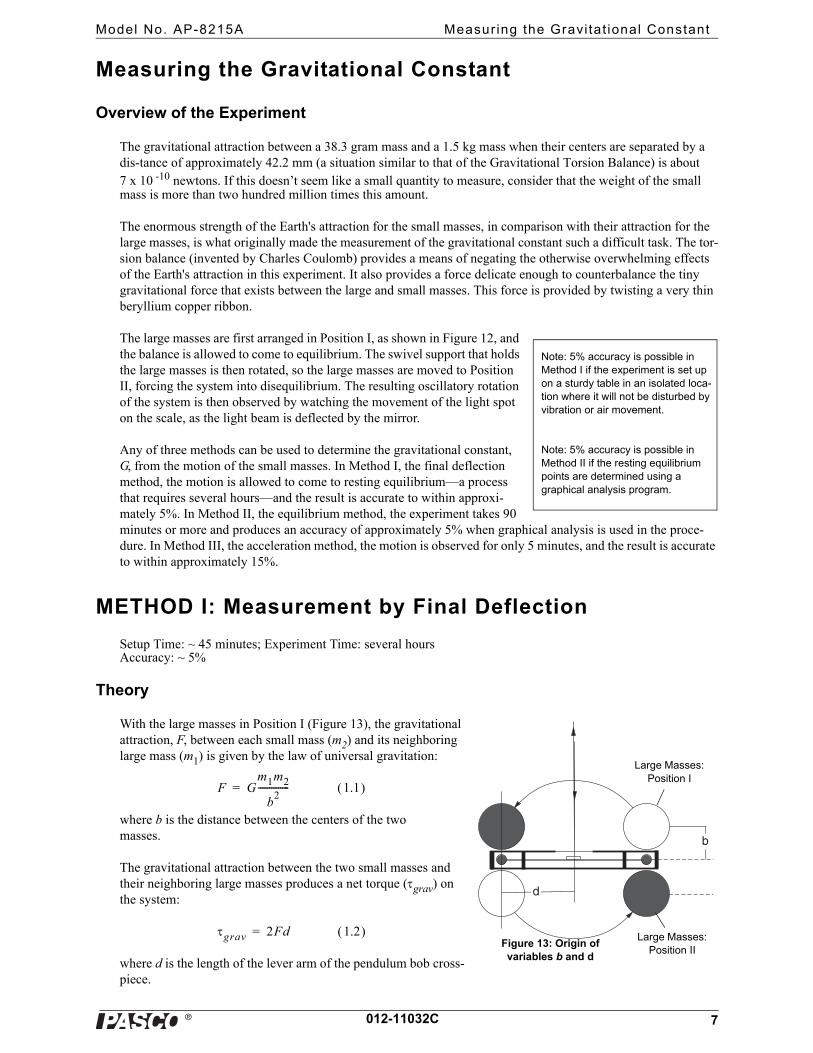
With the large masses in Position I (Figure 13), the gravitational attraction, F, between each small mass (m2) and its neighboring large mass (m1) is given by the law of universal gravitation:
where b is the distance between the centers of the two masses.
The gravitational attraction between the two small masses and their neighboring large masses produces a net torque (grav) on the system:
where d is the length of the lever arm of the pendulum bob cross-piece.
Note: 5% accuracy is possible in Method I if the experiment is set up on a sturdy table in an isolated loca-tion where it will not be disturbed by vibration or air movement.
Note: 5% accuracy is possible in Method II if the resting equilibrium points are determined using a graphical analysis program.
d
b
Large Masses: Position I
Large Masses: Position II
Figure 13: Origin of variables b and d
F Gm1m2
b2
-------------- 1.1 =
grav 2Fd 1.2 =
�
Gravi tat ional Torsion Balance METHOD I : Measurement by Final Def lect ion
8 012-11032C
Since the system is in equilibrium, the twisted torsion band must be supplying an equal and opposite torque. This torque (band) is equal to the torsion constant for the band () times the angle through which it is twisted (), or:
Combining equations 1.1, 1.2, and 1.3, and taking into account that grav = –band, gives:
Rearranging this equation gives an expression for G:
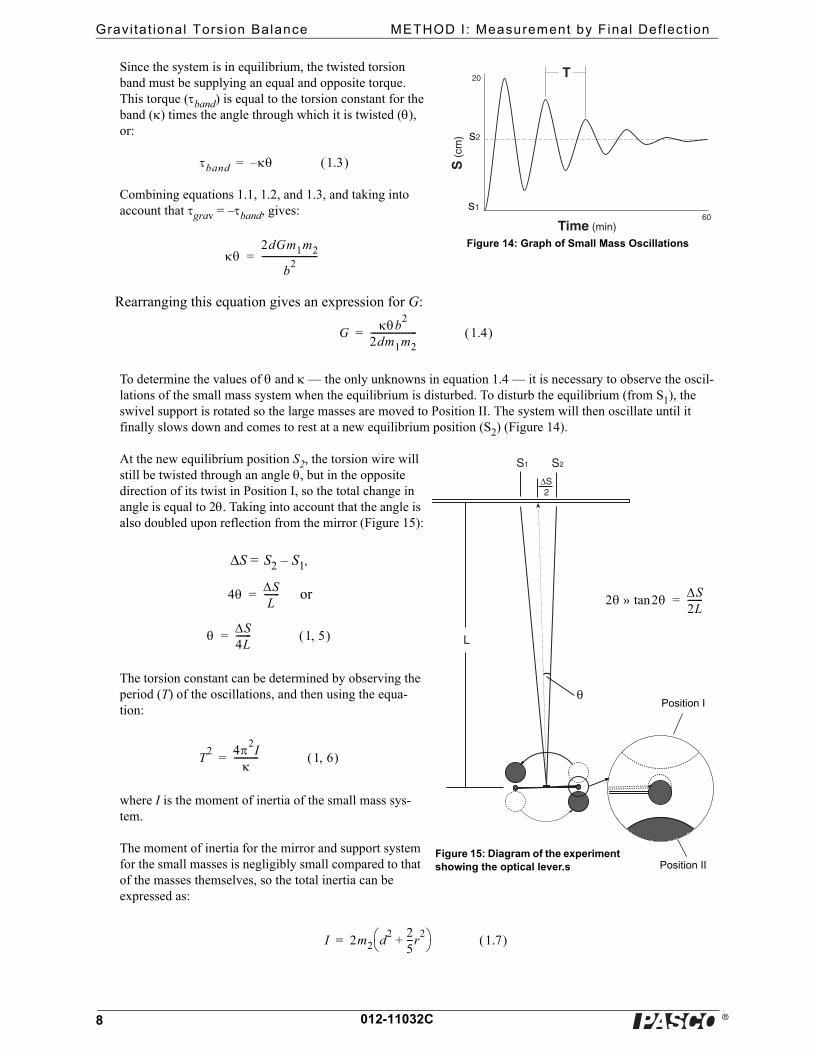
To determine the values of and — the only unknowns in equation 1.4 — it is necessary to observe the oscil-lations of the small mass system when the equilibrium is disturbed. To disturb the equilibrium (from S1), the swivel support is rotated so the large masses are moved to Position II. The system will then oscillate until it finally slows down and comes to rest at a new equilibrium position (S2) (Figure 14).
At the new equilibrium position S2, the torsion wire will still be twisted through an angle , but in the opposite direction of its twist in Position I, so the total change in angle is equal to 2. Taking into account that the angle is also doubled upon reflection from the mirror (Figure 15):
S = S2 – S1,
or
The torsion constant can be determined by observing the period (T) of the oscillations, and then using the equa-tion:
where I is the moment of inertia of the small mass sys-tem.
The moment of inertia for the mirror and support system for the small masses is negligibly small compared to that of the masses themselves, so the total inertia can be expressed as:
T20
60
S(c
m)
Time (min)
s2
s1
Figure 14: Graph of Small Mass Oscillations
band 1.3 –=
2dGm1m2
b2
-------------------------=
Gb
2
2dm1m2--------------------- 1.4 =
S1 S2
ΔS2
θ
L
Figure 15: Diagram of the experiment showing the optical lever.s
Position I
Position II
2 2tan»S2L-------=4 S
L-------=
S4L------- 1 5 =
T2 42
I
----------- 1 6 =
I 2m2 d2 2
5---r
2+
1.7 =
�
Model No. AP-8215A METHOD I : Measurement by Final Def lect ion
9012-11032C
Therefore:
Substituting equations 1.5 and 1.8 into equation 1.4 gives:
All the variables on the right side of equation 1.9 are known or measurable:
r = 9.55 mm
d = 50 mm
b = 42.2 mm
m1 = 1.5 kg
L = (Measure as in step 1 of the setup.)
By measuring the total deflection of the light spot (S) and the period of oscillation (T), the value of G can there-fore be determined.
Procedure
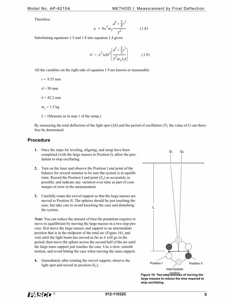
1. Once the steps for leveling, aligning, and setup have been completed (with the large masses in Position I), allow the pen-dulum to stop oscillating.
2. Turn on the laser and observe the Position I end point of the balance for several minutes to be sure the system is at equilib-rium. Record the Position I end point (S1) as accurately as possible, and indicate any variation over time as part of your margin of error in the measurement.
3. Carefully rotate the swivel support so that the large masses are moved to Position II. The spheres should be just touching the case, but take care to avoid knocking the case and disturbing the system.
Note: You can reduce the amount of time the pendulum requires to move to equilibrium by moving the large masses in a two-step pro-cess: first move the large masses and support to an intermediate position that is in the midpoint of the total arc (Figure 16), and wait until the light beam has moved as far as it will go in the period; then move the sphere across the second half of the arc until the large mass support just touches the case. Use a slow, smooth motion, and avoid hitting the case when moving the mass support.
4. Immediately after rotating the swivel support, observe the light spot and record its position (S1).
82m2
d2 2
5---r
2+
T2
-------------------- 1.8 =
G 2Sb2
d2 2
5---r
2+
T2m1Ld
--------------------
1.9 =
S1 S2
L
Position I Position II
Intermediate position
Figure 16: Two-step process of moving the large masses to reduce the time required to stop oscillating.
�
Gravi tat ional Torsion Balance METHOD I : Measurement by Final Def lect ion
10 012-11032C
5. Use a stop watch to determine the time required for one period of oscillation (T). For greater accuracy, include several periods, and then find the average time required for one period of oscillation.
Note: The accuracy of this period value (T) is very important, since the T is squared in the calculation of G.
6. Wait until the oscillations stop, and record the resting equilibrium point (S2).
Analysis
1. Use your results and equation 1.9 to determine the value of G.
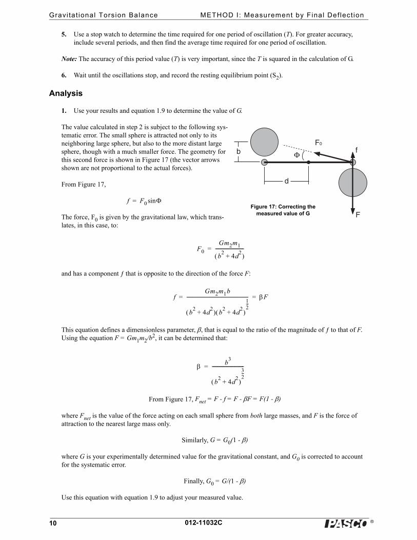
The value calculated in step 2 is subject to the following sys-tematic error. The small sphere is attracted not only to its neighboring large sphere, but also to the more distant large sphere, though with a much smaller force. The geometry for this second force is shown in Figure 17 (the vector arrows shown are not proportional to the actual forces).
From Figure 17,
The force, F0 is given by the gravitational law, which trans-lates, in this case, to:
and has a component ƒ that is opposite to the direction of the force F:
This equation defines a dimensionless parameter, , that is equal to the ratio of the magnitude of ƒ to that of F. Using the equation F = Gm1m2/b2, it can be determined that:
From Figure 17, Fnet = F - f = F - F = F(1 - )
where Fnet is the value of the force acting on each small sphere from both large masses, and F is the force of attraction to the nearest large mass only.
Similarly, G = G0(1 - )
where G is your experimentally determined value for the gravitational constant, and G0 is corrected to account for the systematic error.
Finally, G0 = G/(1 - )
Use this equation with equation 1.9 to adjust your measured value.
Φ
d
bF0
F
f
Figure 17: Correcting the measured value of G
f F0 sin=
F0
Gm2m1
b2
4d2
+ -------------------------=
fGm2m1b
b2
4d2
+ b2
4d2
+
12---
------------------------------------------------------ F= =
b3
b2
4d2
+
32---
----------------------------=
�
Model No. AP-8215A METHOD I I : Measurement by Equi l ibr ium Posi t ions
11012-11032C
METHOD II: Measurement by Equilibrium Positions
Observation Time: ~90+ minutes
Accuracy: ~5%
Theory
When the large masses are placed on the swivel support and moved to either Position I or Position II, the torsion balance oscillates for a time before coming to rest at a new equilibrium position. This oscillation can be described by a damped sine wave with an offset, where the value of the off-set represents the equilibrium point for the balance. By finding the equilib-rium point for both Position I and Position II and taking the difference, the value of S can be obtained. The remainder of the theory is identical to that described in Method I.
Procedure
1. Set up the experiment following steps 1–3 of Method I.
2. Immediately after rotating the swivel support to Position II, observe the light spot. Record the position of the light spot (S) and the time (t) every 15 seconds.Continue recording the position and time for about 45 min-utes.
3. Rotate the swivel support to Position I. Repeat the procedure described in step 2.
Note: Although it is not imperative that step 3 be performed immediately after step 2, it is a good idea to proceed with it as soon as possible in order to minimize the risk that the system will be disturbed between the two mea-surements. Waiting more than a day to perform step 3 is not advised.
Analysis
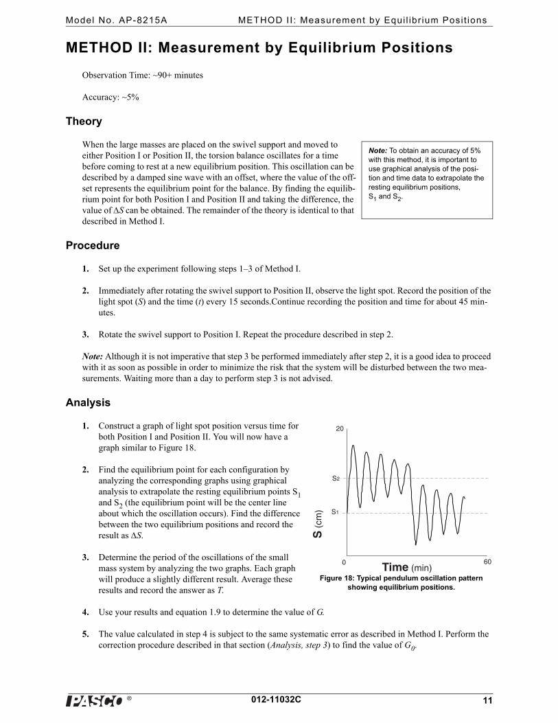
1. Construct a graph of light spot position versus time for both Position I and Position II. You will now have a graph similar to Figure 18.
2. Find the equilibrium point for each configuration by analyzing the corresponding graphs using graphical analysis to extrapolate the resting equilibrium points S1 and S2 (the equilibrium point will be the center line about which the oscillation occurs). Find the difference between the two equilibrium positions and record the result as S.
3. Determine the period of the oscillations of the small mass system by analyzing the two graphs. Each graph will produce a slightly different result. Average these results and record the answer as T.
4. Use your results and equation 1.9 to determine the value of G.
5. The value calculated in step 4 is subject to the same systematic error as described in Method I. Perform the correction procedure described in that section (Analysis, step 3) to find the value of G0.
Note: To obtain an accuracy of 5% with this method, it is important to use graphical analysis of the posi-tion and time data to extrapolate the resting equilibrium positions, S1 and S2.
60
S(c
m)
Time (min)
S2
S1
0
20
Figure 18: Typical pendulum oscillation pattern showing equilibrium positions.
�
Gravi tat ional Torsion Balance METHOD I I I : Measurement by Accelerat ion
12 012-11032C
METHOD III: Measurement by Acceleration
Observation Time: ~ 5 minutes
Accuracy: ~ 15%
Theory
With the large masses in Position I, the gravitational attraction, F, between each small mass (m2) and its neigh-boring large mass (m1) is given by the law of universal gravitation:
This force is balanced by a torque from the twisted torsion ribbon, so that the system is in equilibrium. The angle of twist, , is measured by noting the position of the light spot where the reflected beam strikes the scale. This position is carefully noted, and then the large masses are moved to Position II. The position change of the large masses disturbs the equilibrium of the system, which will now oscillate until friction slows it down to a new equilibrium position.
Since the period of oscillation of the small masses is long (approximately 10 minutes), they do not move signifi-cantly when the large masses are first moved from Position I to Position II. Because of the symmetry of the setup, the large masses exert the same gravitational force on the small masses as they did in Position I, but now in the opposite direction. Since the equilibrating force from the torsion band has not changed, the total force (Ftotal) that is now acting to accelerate the small masses is equal to twice the original gravitational force from the large masses, or:
Each small mass is therefore accelerated toward its neighboring large mass, with an initial acceleration (a0) that is expressed in the equation:
Of course, as the small masses begin to move, the torsion ribbon becomes more and more relaxed so that the force decreases and their acceleration is reduced. If the system is observed over a relatively long period of time, as in Method I, it will be seen to oscillate. If, however, the acceleration of the small masses can be measured before the torque from the torsion ribbon changes appreciably, equation 3.3 can be used to determine G. Given the nature of the motion—damped harmonic—the initial acceleration is constant to within about 5% in the first one tenth of an oscillation. Reasonably good results can therefore be obtained if the acceleration is measured in the first minute after rearranging the large masses, and the following relationship is used:
F Gm1m2
b2
-------------- 3.1 =
Ftotal 2F 2Gm1m2
b2
-------------- 3.2 = =
m2a0 2Gm1m2
b2
-------------- 3.3 =
G b2 a0
2m1---------- 3.4 =
�
Model No. AP-8215A METHOD I I I : Measurement by Accelerat ion
13012-11032C
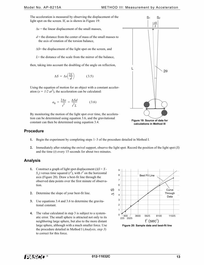
The acceleration is measured by observing the displacement of the light spot on the screen. If, as is shown in Figure 19:
s = the linear displacement of the small masses,
d = the distance from the center of mass of the small masses to the axis of rotation of the torsion balance,
S= the displacement of the light spot on the screen, and
L= the distance of the scale from the mirror of the balance,
then, taking into account the doubling of the angle on reflection,
Using the equation of motion for an object with a constant acceler-ation (x = 1/2 at2), the acceleration can be calculated:
By monitoring the motion of the light spot over time, the accelera-tion can be determined using equation 3.6, and the gravitational constant can then be determined using equation 3.4.
Procedure
1. Begin the experiment by completing steps 1–3 of the procedure detailed in Method I.
2. Immediately after rotating the swivel support, observe the light spot. Record the position of the light spot (S) and the time (t) every 15 seconds for about two minutes.
Analysis
1. Construct a graph of light spot displacement (S = S - S1) versus time squared (t2), with t2 on the horizontal axis (Figure 20). Draw a best-fit line through the observed data points over the first minute of observa-tion.
2. Determine the slope of your best-fit line.
3. Use equations 3.4 and 3.6 to determine the gravita-tional constant.
4. The value calculated in step 3 is subject to a system-atic error. The small sphere is attracted not only to its neighboring large sphere, but also to the more distant large sphere, although with a much smaller force. Use the procedure detailed in Method I (Analysis, step 3) to correct for this force.
S1 S2
ΔS2
2θL
Figure 19: Source of data for calculations in Method III
S s2Ld
------ 3.5 =
a02s
t2
--------- Sd
t2L
---------- 3.6 = =
ΔS
0
1
2
3
4
5
6
7
8
9
225 2025900 3600 5625 8100 11025
t2 (sec2)
Best Fit Line
Curve Through
Data
Figure 20: Sample data and best-fit line
�
Gravi tat ional Torsion Balance Maintenance
14 012-11032C
Maintenance
Replacing the Torsion Ribbon Assembly
If the torsion ribbon breaks, replace it as follows:
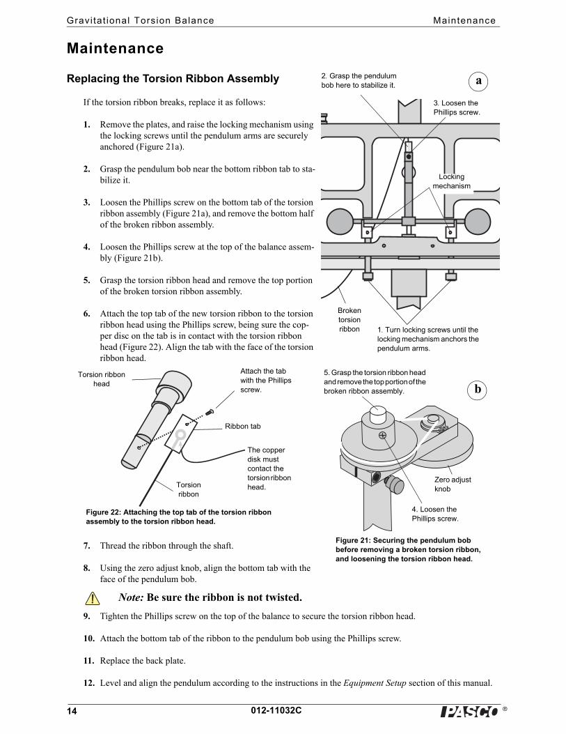
1. Remove the plates, and raise the locking mechanism using the locking screws until the pendulum arms are securely anchored (Figure 21a).
2. Grasp the pendulum bob near the bottom ribbon tab to sta-bilize it.
3. Loosen the Phillips screw on the bottom tab of the torsion ribbon assembly (Figure 21a), and remove the bottom half of the broken ribbon assembly.
4. Loosen the Phillips screw at the top of the balance assem-bly (Figure 21b).
5. Grasp the torsion ribbon head and remove the top portion of the broken torsion ribbon assembly.
6. Attach the top tab of the new torsion ribbon to the torsion ribbon head using the Phillips screw, being sure the cop-per disc on the tab is in contact with the torsion ribbon head (Figure 22). Align the tab with the face of the torsion ribbon head.
7. Thread the ribbon through the shaft.
8. Using the zero adjust knob, align the bottom tab with the face of the pendulum bob.
9. Tighten the Phillips screw on the top of the balance to secure the torsion ribbon head.
10. Attach the bottom tab of the ribbon to the pendulum bob using the Phillips screw.
11. Replace the back plate.
12. Level and align the pendulum according to the instructions in the Equipment Setup section of this manual.
Broken torsion ribbon 1. Turn locking screws until the
locking mechanism anchors the pendulum arms.
Locking mechanism
3. Loosen the Phillips screw.
4. Loosen the Phillips screw.
5. Grasp the torsion ribbon head and remove the top portion of the broken ribbon assembly. b
Figure 21: Securing the pendulum bob before removing a broken torsion ribbon, and loosening the torsion ribbon head.
Zero adjust knobTorsion
ribbon
The copper disk must contact the torsion ribbon head.
Ribbon tab
Torsion ribbon head
Attach the tab with the Phillips screw.
Figure 22: Attaching the top tab of the torsion ribbon assembly to the torsion ribbon head.
Note: Be sure the ribbon is not twisted.
2. Grasp the pendulum bob here to stabilize it. a
�
Model No. AP-8215A Transport ing and Stor ing
15012-11032C
Transporting and Storing
1. To prepare the Gravitational Torsion Balance for transporting or storing:
a.Remove the front plate.
b.Raise the locking mechanism to securely anchor the pendulum bob.
c.Check to be sure that the torsion ribbon is hanging straight down the center of the tube. If it is not, lower the locking mechanisms, be sure the torsion wire is centered, and raise the locking mechanisms again. Repeat as necessary until the ribbon is centered in the tube.
d.Reinstall the packing foam into the chamber to secure the pendulum bob.
e.Replace the plate.
2. The Gravitational Torsion Balance may be stored flat in its shipping container.
3. Store in a cool, dry place, and protect the device from any jarring or rough handling.
Safety Precaution
The large masses are made of tungsten, which is not toxic. Be careful not to drop the 1.5 kg masses.
Technical Support
Feedback
If you have any comments about the product or manual, please let us know. If you have any suggestions on alter-nate experiments or find a problem in the manual, please tell us. PASCO appreciates any customer feedback. Your input helps us evaluate and improve our product.
Contacting Technical Support
Before you call PASCO technical support, have the apparatus and this user's guide available. Please note the follow-ing:
• Product name and model number (e.g., Gravitational Torsion Balance, AP-8215A)
• Approximate age of the product;
• Detailed description of the problem/sequence of events required to duplicate the problem.
For assistance with any PASCO product, contact PASCO at:
For the latest information about this product or the latest revision of the Instruction Manual, visit the PASCO web site and enter AP-8215A in the Search window.
Address: PASCO scientific10101 Foothills Blvd.Roseville, CA 95747-7100
Phone: +1 916 462 8384 (worldwide)877-373-0300 (U.S.)
Web: www.pasco.com
Email: [email protected]

�
Gravi tat ional Torsion Balance Technical Support
16 012-11032C