Embed Size (px)
Citation preview
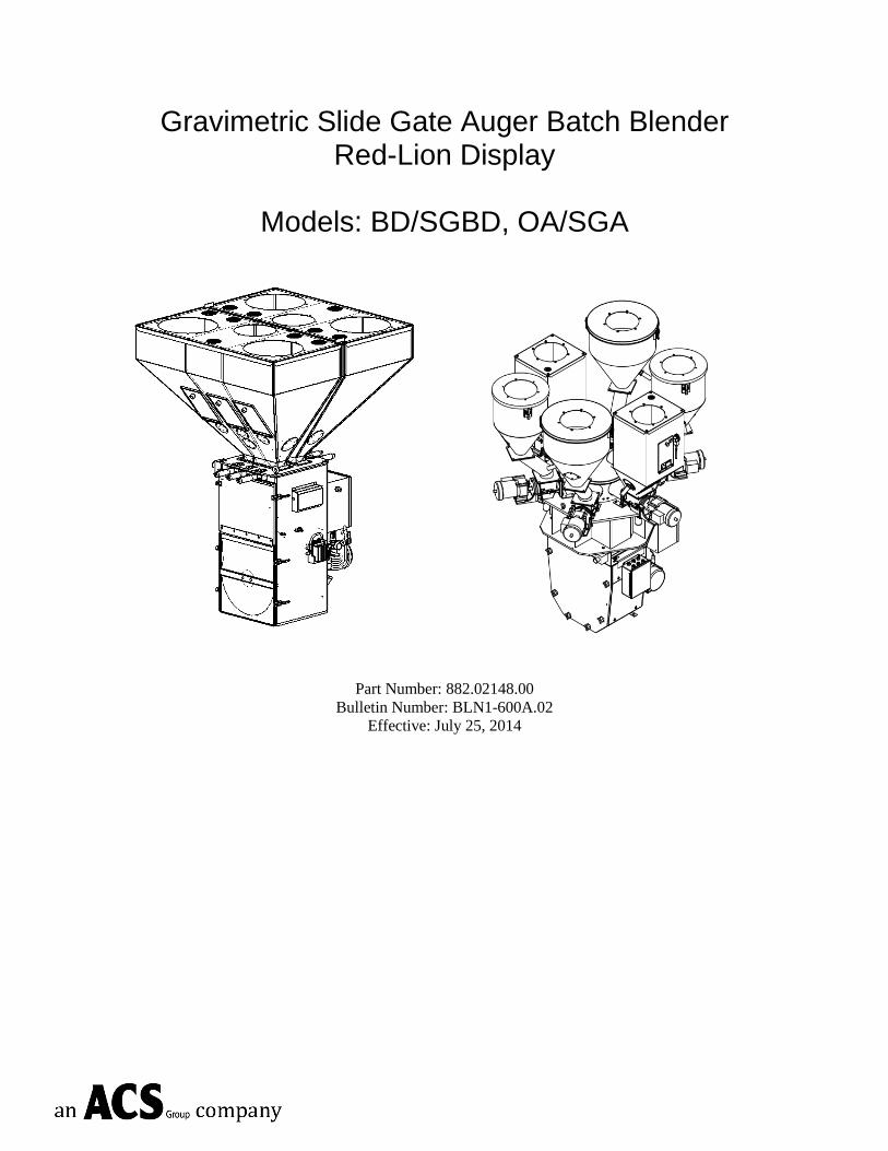
Gravimetric Slide Gate Auger Batch Blender Red-Lion Display
Models: BD/SGBD, OA/SGA
Part Number: 882.02148.00
Bulletin Number: BLN1-600A.02
Effective: July 25, 2014
ii
Write Down Your Serial and Software Revision Numbers Here For Future Reference: _________________________ _________________________ _________________________ _________________________ _________________________ _________________________
We are committed to a continuing program of product improvement.
Specifications, appearance, and dimensions described in this manual are subject to change without notice.
DCN No. ____________
© Copyright 2014
All rights reserved.
iii
Shipping Info
Unpacking and Inspection
You should inspect your equipment for possible shipping damage.
Thoroughly check the equipment for any damage that might have occurred in transit, such as
broken or loose wiring and components, loose hardware and mounting screws, etc.
In the Event of Shipping Damage
According to the contract terms and conditions of the Carrier, the responsibility of the
Shipper ends at the time and place of shipment.
Notify the transportation company’s local agent if you discover damage.
Hold the damaged goods and packing material for the examining agent’s inspection. Do not
return any goods before the transportation company’s inspection and authorization.
File a claim with the transportation company. Substantiate the claim by referring to the
agent’s report. A certified copy of our invoice is available upon request. The original Bill of
Lading is attached to our original invoice. If the shipment was prepaid, write us for a
receipted transportation bill.
Advise customer service regarding your wish for assistance and to obtain an RMA (return
material authorization) number.
If the Shipment is Not Complete
Check the packing list as back-ordered items are noted on the packing list. In addition to the
equipment itself, you should have:
Bill of lading
Packing list
Operating and Installation packet
Electrical schematic and panel layout drawings
Component instruction manuals (if applicable)
Re-inspect the container and packing material to see if you missed any smaller items during
unpacking.
If the Shipment is Not Correct
If the shipment is not what you ordered, contact the shipping department immediately. For
immediate assistance, please contact the correct facility located in the technical assistance
section of this manual. Have the order number and item number available. Hold the items
until you receive shipping instructions.
Storage and Handling
Keep equipment in a clean, dry location when storing/handling. Environment should not
exceed -25°C to 65°C (-13°F to 149°F) with no icing.
iv
Returns
Do not return any damaged or incorrect items until you receive shipping instructions from the
shipping department.
Credit Returns
Prior to the return of any material, authorization must be given by the manufacturer. A
RMA number will be assigned for the equipment to be returned.
Reason for requesting the return must be given.
ALL returned material purchased from the manufacturer returned is subject to 15% ($75.00
minimum) restocking charge.
ALL returns are to be shipped prepaid.
The invoice number and date or purchase order number and date must be supplied.
No credit will be issued for material that is not within the manufacturer’s warranty period
and/or in new and unused condition, suitable for resale.
Warranty Returns
Prior to the return of any material, authorization must be given by the manufacturer. A
RMA number will be assigned for the equipment to be returned.
Reason for requesting the return must be given.
All returns are to be shipped prepaid.
The invoice number and date or purchase order number and date must be supplied.
After inspecting the material, a replacement or credit will be given at the manufacturer’s
discretion. If the item is found to be defective in materials or workmanship, and it was
manufactured by our company, purchased components are covered under their specific
warranty terms.
v
Table of Contents
CHAPTER 1: SAFETY ................................................................ 8
1-1 How to Use This Manual ............................................................................................ 8 Safety Symbols Used in this Manual ................................................................... 8
1-2 Warnings and Precautions ....................................................................................... 11 1-3 Responsibility .......................................................................................................... 12
General Responsibility .......................................................................................12 Operator Responsibility ......................................................................................12 Maintenance Responsibility ...............................................................................13 Reporting a Safety Defect ..................................................................................14
CHAPTER 2: FUNCTIONAL DESCRIPTION ........................... 15
2-1 Models Covered in This Manual ............................................................................... 15 2-2 General Description ................................................................................................. 15
Accessories .......................................................................................................15 Customer Service ..............................................................................................15
2-3 Typical Features and Components .......................................................................... 18 Mechanical Features ..........................................................................................18
Slide Gate Blenders ............................................................................................. 18 Auger Blenders .................................................................................................... 18 Both Blender Styles ............................................................................................. 18
Slide Gate & Auger Blender System Component Description ............................18 Material Supply Hoppers ..................................................................................... 19 Slide Gates – BD/SGBD ...................................................................................... 20 Weigh Hopper ...................................................................................................... 21 Auger Metering Assemblies ................................................................................ 21 Mix Chamber ....................................................................................................... 24 “HC” Mixer ......................................................................................................... 25
Controller Features ............................................................................................26 2-4 Optional Components .............................................................................................. 35
Pneumatic Slide Gate below Mixer ....................................................................35 Low Level Sensors .............................................................................................35 Remote Touch Screen .......................................................................................35 Mezzanine and Floor Stands .............................................................................36 Regrind Auger Metering (R.A.M.) Hopper ..........................................................36 Additive Feeder Hopper .....................................................................................37 Take-off Compartments .....................................................................................37
2-5 Safety Features ....................................................................................................... 37 Safety Circuit Standards ....................................................................................37 Fail Safe Operation ............................................................................................38 Safety Device Lock-Outs ....................................................................................38 Twist Cap Plug Connected to Each Feeder Auger Motor ...................................39
CHAPTER 3: INSTALLATION .................................................. 41
3-1 Uncrating the Equipment ......................................................................................... 41 3-2 Mechanical Installation ............................................................................................ 41
Site Requirements .............................................................................................42
vi
Mounting Configurations ....................................................................................42 Machine Mount .................................................................................................... 42 Mezzanine Mount ................................................................................................ 43 Floor Mount (Central Blender) ............................................................................ 44
3-3 Electrical Connections ............................................................................................. 44 3-4 Pneumatic Connections ........................................................................................... 46 3-5 Initial Set-up............................................................................................................. 46
Mechanical Set-up .............................................................................................47 Stroke Limiters for Metering Gates ..................................................................... 47 Weigh Hopper Installation ................................................................................... 47 Load Cell Adjustment – OA/SGA Models .......................................................... 47 Final Connections ................................................................................................ 49
Controller Set-up ................................................................................................49 Blender Calibration .............................................................................................. 50 Alarm Setup ......................................................................................................... 54 Network Setup ..................................................................................................... 56 Display IP Address and Setting the Time/Date ................................................... 56 Configure the blender for LBS or KGS. .............................................................. 57 Mixer and Dump Setup ........................................................................................ 57
3-6 Initial Startup ............................................................................................................ 58
CHAPTER 4: OPERATION ....................................................... 59
4-1 Start-up .................................................................................................................... 59 General Operation .............................................................................................59 Quick Start Procedure ........................................................................................60
New Recipes ........................................................................................................ 60 Existing Recipes .................................................................................................. 60
4-2 Operation Procedures .............................................................................................. 61 Operator Displays ..............................................................................................61 Recipe Entry Formats ........................................................................................66
“EZ Recipe” Mode (Most common in injection molding) .................................. 67 “Percentage” Mode (Most common in extrusion and blow molding) ................. 69 “Parts” Mode (Often used in Compounding Applications) ................................. 69
Recipe Setup .....................................................................................................69 Mixer and Dump Setup ......................................................................................73 Alarm Messages ................................................................................................75 Blending Mode Sequence ..................................................................................76 Printer Features .................................................................................................77 Color Changes ...................................................................................................78
4-3 Shut-down ............................................................................................................... 80
CHAPTER 5: MAINTENANCE ................................................. 81
5-1 Preventative Maintenance Schedule ........................................................................ 81 5-2 Preventative Maintenance ....................................................................................... 82 5-3 Corrective Maintenance ........................................................................................... 83
CHAPTER 6: TROUBLESHOOTING ....................................... 85
6-1 Introduction .............................................................................................................. 85
CHAPTER 7: APPENDIX .......................................................... 90
vii
7-1 Technical Specifications .......................................................................................... 90 Annex B Information ..........................................................................................90
7-2 Drawings and Diagrams for BD and SGBD .............................................................. 91 Final Assembly ..................................................................................................91 Standard Mixer Sub-Assembly……………………………………………………….93 Mixer Sub-Assembly with Optional Bowl Mixer ..................................................94 Hopper Sub-assembly .......................................................................................96 Hopper R.A.M. (Regrind Auger Metering) Sub-Assembly (Optional) ..................97 Hopper Additive Feeder Sub-Assembly (Optional) .............................................98 Weigh Hopper Sub-assembly ............................................................................99 Slide Gate Sub-assembly ................................................................................. 100 Knife Gate Sub-assembly HD (Optional) .......................................................... 101 Knife Gate Sub-assembly RD (Optional) .......................................................... 102 Control Panel Layout ....................................................................................... 103
7-3 Spare Parts Kits for BD and SGBD *...................................................................... 105 7-4 Drawings & Diagrams for OA/SGA ........................................................................ 106
Typical OA/SGA Model Assembly Overview .................................................... 106 Typical OA/SGA Model Assembly Parts List .................................................... 107 OA/SGA-060 Weigh Hopper Assembly Parts List ............................................ 108 Mixer Assembly HC-Style Parts List ................................................................. 109 Air Valve Connections Parts List ...................................................................... 112 Heavy Duty Feeder Assembly Parts List .......................................................... 113 Agitated Supply Hopper Assembly ................................................................... 114 16” Supply Hopper Parts List ........................................................................... 115 20” Supply Hopper Parts List ........................................................................... 116 OA/SGA Feeder Assembly Parts List ............................................................... 117
7-5 Spare Parts List ..................................................................................................... 118 Slide Gate Gravimetric Batch Blending Systems .............................................. 118 Auger Gravimetric Batch Blending Systems ..................................................... 118
7-6 Addendum (Service Supervisor Information).......................................................... 120 7-7 Blender Identification (Serial Number) Tag ............................................................ 137 7-8 Technical Assistance ............................................................................................. 138
BLN1-600A.1 Chapter 1: Safety 8 of 138
Chapter 1: Safety
1-1 How to Use This Manual
Use this manual as a guide and reference for installing, operating, and maintaining your
blender. The purpose is to assist you in applying efficient, proven techniques that enhance
equipment productivity.
This manual covers only light corrective maintenance. No other maintenance should be
undertaken without first contacting a service engineer.
The Functional Description section outlines models covered, standard features, and safety
features. Additional sections within the manual provide instructions for installation, pre-
operational procedures, operation, preventive maintenance, and corrective maintenance.
The Installation chapter includes required data for receiving, unpacking, inspecting, and setup
of the blender. We can also provide the assistance of a factory-trained technician to help train
your operator(s) for a nominal charge. This section includes instructions, checks, and
adjustments that should be followed before commencing with operation of the blender.
These instructions are intended to supplement standard shop procedures performed at shift,
daily, and weekly intervals.
The Operation chapter includes a description of electrical and mechanical controls, in
addition to information for operating the blender safely and efficiently.
The Maintenance chapter is intended to serve as a source of detailed assembly and
disassembly instructions for those areas of the equipment requiring service. Preventive
maintenance sections are included to ensure that your blender provides excellent, long
service.
The Troubleshooting chapter serves as a guide for identification of most common problems.
Potential problems are listed, along with possible causes and related solutions.
The Appendix contains technical specifications, drawings, schematics, parts lists, and
available options. Refer to this section for a listing of spare parts for purchase. Have your
serial number and model number ready when ordering.
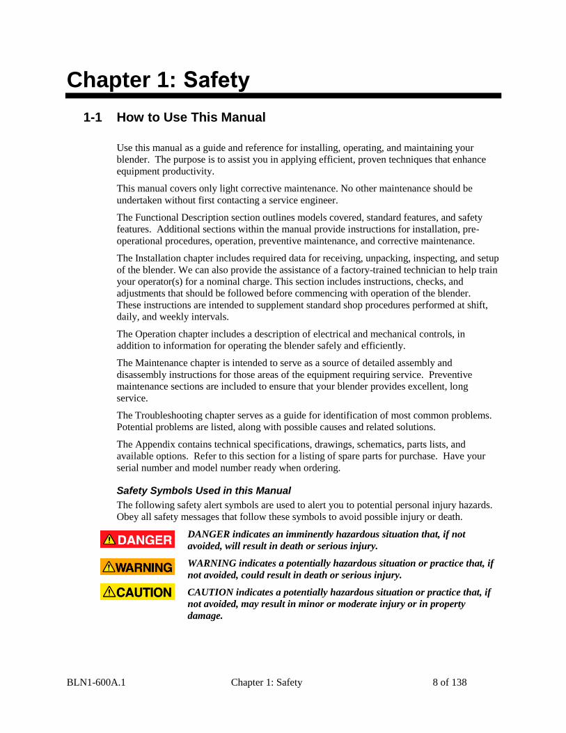
Safety Symbols Used in this Manual
The following safety alert symbols are used to alert you to potential personal injury hazards.
Obey all safety messages that follow these symbols to avoid possible injury or death.
DANGER indicates an imminently hazardous situation that, if not
avoided, will result in death or serious injury.
WARNING indicates a potentially hazardous situation or practice that, if
not avoided, could result in death or serious injury.
CAUTION indicates a potentially hazardous situation or practice that, if
not avoided, may result in minor or moderate injury or in property
damage.
BLN1-600A.1 Chapter 1: Safety 9 of 138
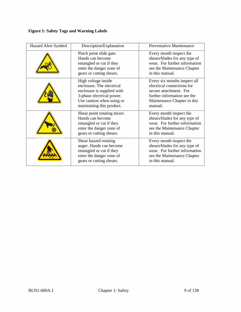
Figure 1: Safety Tags and Warning Labels
Hazard Alert Symbol Description/Explanation Preventative Maintenance
Pinch point slide gate.
Hands can become
entangled or cut if they
enter the danger zone of
gears or cutting shears.
Every month inspect the
shears/blades for any type of
wear. For further information
see the Maintenance Chapter
in this manual.
High voltage inside
enclosure. The electrical
enclosure is supplied with
3-phase electrical power.
Use caution when using or
maintaining this product.
Every six months inspect all
electrical connections for
secure attachment. For
further information see the
Maintenance Chapter in this
manual.
Shear point rotating mixer.
Hands can become
entangled or cut if they
enter the danger zone of
gears or cutting shears.
Every month inspect the
shears/blades for any type of
wear. For further information
see the Maintenance Chapter
in this manual.
Shear hazard rotating
auger. Hands can become
entangled or cut if they
enter the danger zone of
gears or cutting shears.
Every month inspect the
shears/blades for any type of
wear. For further information
see the Maintenance Chapter
in this manual.
BLN1-600A.1 Chapter 1: Safety 10 of 138
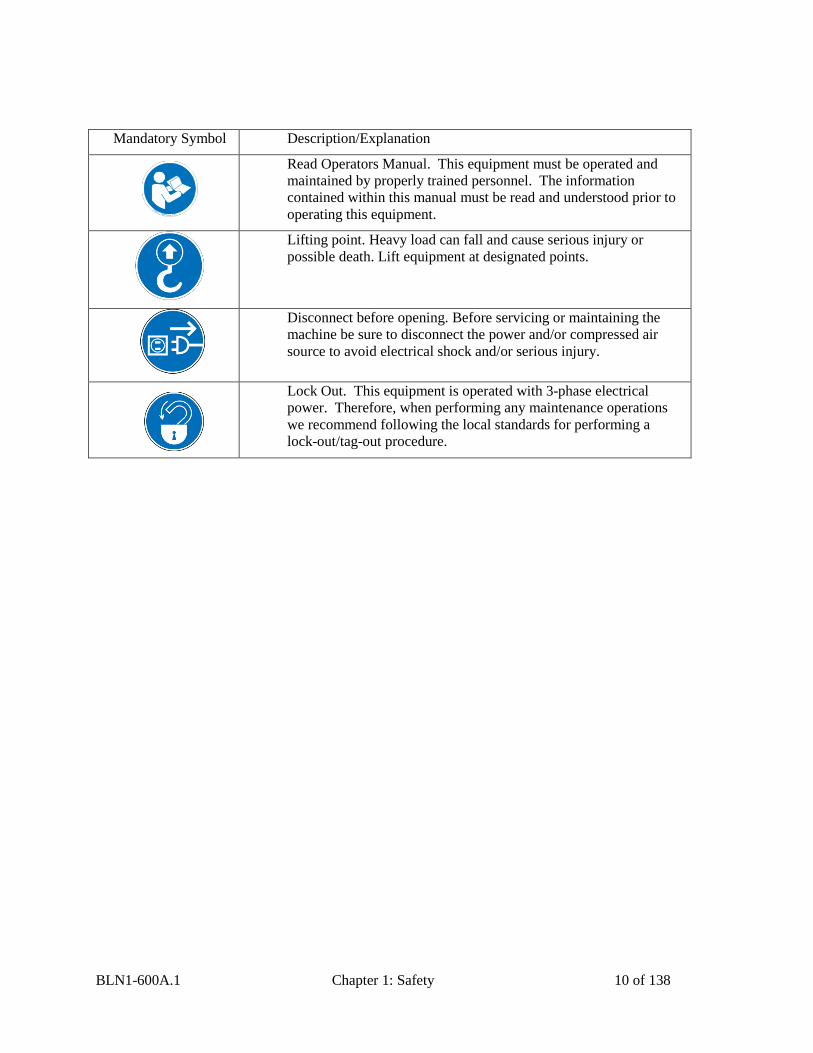
Mandatory Symbol Description/Explanation
Read Operators Manual. This equipment must be operated and
maintained by properly trained personnel. The information
contained within this manual must be read and understood prior to
operating this equipment.
Lifting point. Heavy load can fall and cause serious injury or
possible death. Lift equipment at designated points.
Disconnect before opening. Before servicing or maintaining the
machine be sure to disconnect the power and/or compressed air
source to avoid electrical shock and/or serious injury.
Lock Out. This equipment is operated with 3-phase electrical
power. Therefore, when performing any maintenance operations
we recommend following the local standards for performing a
lock-out/tag-out procedure.

BLN1-600A.1 Chapter 1: Safety 11 of 138
1-2 Warnings and Precautions Our equipment is designed to provide safe and reliable operation when installed and operated
within design specifications, following national and local safety codes. This may include, but
is not limited to OSHA, NEC, CSA, SPI, and any other local, national and international
regulations.
To avoid possible personal injury or equipment damage when installing, operating, or
maintaining this equipment, use good judgment and follow these safe practices:
Read and follow these operation and installation instructions when installing,
operating, and maintaining this equipment. If these instructions become
damaged or unreadable, additional copies are available from the manufacturer.
Follow all SAFETY CODES.
Keep fingers away from slide gates, augers, clean-outs, and calibration hatches.
Automatic operation may start unexpectedly, A PINCH HAZARD CAPABLE OF
CAUSING BODILY INJURY EXISTS ANY TIME THE POWER IS ON.
Wear SAFETY GLASSES and WORK GLOVES.
Work only with approved tools and devices.
Disconnect and/or lock out power and compressed air before servicing or maintaining
the equipment.
Use care when LOADING, UNLOADING, RIGGING, or MOVING this
equipment.
Operate this equipment within design specifications.
OPEN, TAG, and LOCK ALL DISCONNECTS before working on equipment.
You should remove the fuses and carry them with you.
NEVER PUT FINGERS OR TOOLS IN AN AUGER OR SLIDE GATE AREA.
Make sure the equipment and components are properly GROUNDED before you
switch on power.
Do not restore power until you remove all tools, test equipment, etc., and the
equipment and related components are fully reassembled.
Only PROPERLY TRAINED personnel familiar with the information in this
manual should work on this equipment.
We have long recognized the importance of safety and have designed and manufactured our
equipment with operator safety as a prime consideration. We expect you, as a user, to abide
by the foregoing recommendations in order to make operator safety a reality.
BLN1-600A.1 Chapter 1: Safety 12 of 138
1-3 Responsibility These machines are constructed for maximum operator safety when used under standard
operating conditions and when recommended instructions are followed in the maintenance
and operation of the machine.
All personnel engaged in the use of the machine should become familiar with its operation as
described in this manual.
Proper operation of the machine promotes safety for the operator and all workers in its
vicinity.
Becoming familiar with materials, inspection, speed limitations, and guard maintenance and
total user responsibility will assist you in learning potential areas in need of observation for
danger.
Each individual must take responsibility for observing the prescribed safety rules as outlined.
All caution, warning and danger signs must be observed and obeyed. All actual or potential
danger areas must be reported to your immediate supervisor.
General Responsibility
No matter who you are, safety is important. Owners, operators and maintenance personnel
must realize that every day, safety is a vital part of their jobs.
If your main concern is loss of productivity, remember that production is always affected in a
negative way following an accident. The following are some of the ways that accidents can
affect your production:
Loss of a skilled operator (temporarily or permanently)
Breakdown of shop morale
Costly damage to equipment
Downtime
An effective safety program is responsible and economically sound.
Organize a safety committee or group, and hold regular meetings. Promote this group from
the management level. Through this group, the safety program can be continually reviewed,
maintained, and improved. Keep minutes or a record of the meetings.
Hold daily equipment inspections in addition to regular maintenance checks. You will keep
your equipment safe for production and exhibit your commitment to safety.
Please read and use this manual as a guide to equipment safety. This manual contains safety
warnings throughout, specific to each function and point of operation.
Operator Responsibility
The operator’s responsibility does not end with efficient production. The operator usually has
the most daily contact with the equipment and intimately knows its capabilities and
limitations.
Plant and personnel safety is sometimes forgotten in the desire to meet incentive rates, or
through a casual attitude toward machinery formed over a period of months or years. Your
employer probably has established a set of safety rules in your workplace. Those rules, this
manual, or any other safety information will not keep you from being injured while operating
your equipment.
BLN1-600A.1 Chapter 1: Safety 13 of 138
Learn and always use safe operation. Cooperate with co-workers to promote safe practices.
Immediately report any potentially dangerous situation to your supervisor or appropriate
person.
REMEMBER:
NEVER place your hands or any part of your body in any dangerous location.
NEVER operate, service, or adjust the blender without appropriate training and first
reading and understanding this manual.
NEVER try to pull material out of the blender with your hands while it is running!
Before you start the blender check the following:
Remove all tools from the unit;
Be sure no objects (tools, nuts, bolts, clamps, bars) are laying in the metering or If your
blender has been inoperative or unattended, check all settings before starting the unit.
Report the following occurrences IMMEDIATELY:
unsafe operation or condition
unusual blender action
leakage
improper maintenance
At the beginning of your shift and after breaks, verify that the controls and
other auxiliary equipment are functioning properly.
Keep all safety guards in place and in good repair. NEVER attempt to
bypass, modify, or remove safety guards. Such alteration is not only unsafe,
but will void the warranty on your equipment.
When changing control settings to perform a different mode of operation, be
sure selector switches are correctly positioned. Locking selector switches
should only be adjusted by authorized personnel and the keys removed after
setting.
NEVER stand or sit where you could slip or stumble into the blender while
working on it.
DO NOT wear loose clothing or jewelry, which can be caught while working
on an blender. In addition, cover or tie back long hair.
Clean the blender and surrounding area DAILY, and inspect the machine
for loose, missing or broken parts.
Shut off power to the blender when it is not in use. Turn the switch to the
OFF position, or unplug it from the power source.
BLN1-600A.1 Chapter 1: Safety 14 of 138
Maintenance Responsibility
Proper maintenance is essential to safety. If you are a maintenance worker, you must make
safety a priority to effectively repair and maintain equipment.
Before removing, adjusting, or replacing parts on a machine, remember to turn off all electric
supplies and all accessory equipment at the machine, and disconnect and lockout electrical
power. Attach warning tags to the disconnect switch.
When you need to perform maintenance or repair work on a blender above floor level, use a
solid platform or a hydraulic elevator. If there is a permanently installed catwalk around your
blender, use it. The work platform should have secure footing and a place for tools and parts.
DO NOT climb on unit, machines, or work from ladders.
If you need to repair a large component, use appropriate handling equipment. Before you use
handling equipment (portable “A” frames, electric boom trucks, fork trucks, overhead cranes)
be sure the load does not exceed the capacity of the handling equipment or cause it to become
unstable.
Carefully test the condition of lifting cables, chains, ropes, slings, and hooks before using
them to lift a load.
Be sure that all non-current carrying parts are correctly connected to earth ground with an
electrical conductor that complies with current codes. Install in accordance with national and
local codes.
When you have completed the repair or maintenance procedure, check your work and remove
your tools, rigging, and handling equipment.
Do not restore power to the blender until all persons are clear of the area. DO NOT start and
run the unit until you are sure all parts are functioning correctly.
BEFORE you turn the blender over to the operator for production, verify all enclosure
panels, guards and safety devices are in place and functioning properly.
Reporting a Safety Defect
If you believe that your equipment has a defect that could cause injury, you should
immediately discontinue its use and inform the manufacturer.
The principle factors that can result in injury are failure to follow proper operating procedures
(i.e. lockout/tagout), or failure to maintain a clean and safe working environment.

BLN1-600A.1 Chapter 2: Functional Description 15 of 138
Chapter 2: Functional Description
2-1 Models Covered in This Manual This manual provides operation, installation, and maintenance instructions for the BD/SGBD
Series slide gate blenders and OA/SGA Series auger blenders of various blending rates and
specifications. See below for a list of available models.
BD, SGBD Blenders OA, SGA Blenders
200 "002"
500 "012"
900 "060"
2500
4000
6000
Model numbers are listed on the serial tag. Make sure you know the model and serial number
of your equipment before contacting the manufacturer for parts or service.
Blending systems are as varied as the applications they service. All slide gate blenders are
sized to meet the specific requirements stated by the Customer at the time of purchase.
2-2 General Description All blenders are designed to blend plastic pellets and regrind, and supply the blended material
to the processing machine. Standard equipment is not designed to blend powder or any other
materials.
Accessories
The manufacturer offers a variety of standard options for blenders including floor stands,
RAM feeders, loading equipment, etc. All accessories are designed and manufactured to
ensure proper results for your application.
Customer Service
The intent of this manual is to familiarize the operator and maintenance personnel with these
blenders and help your organization get the maximum service from your equipment. If you
have any questions regarding installation, service, repair, custom equipment, or applications,
please do not hesitate to contact us for the information required. Prices for additional
equipment, accessories, or repair parts will be furnished promptly upon request.
If you desire to use a blender for an application other than that for which it
was purchased, please contact your sales representative or our factory to
verify compatibility of the equipment with the new process. Misapplication
of the equipment could result in injury to the operator or damage to the
equipment.
BLN1-600A.1 Chapter 2: Functional Description 16 of 138
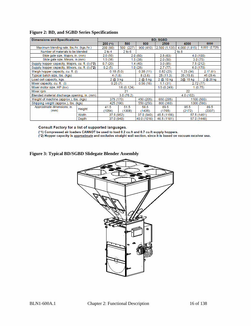
Figure 2: BD, and SGBD Series Specifications
Figure 3: Typical BD/SGBD Slidegate Blender Assembly
BLN1-600A.1 Chapter 2: Functional Description 17 of 138
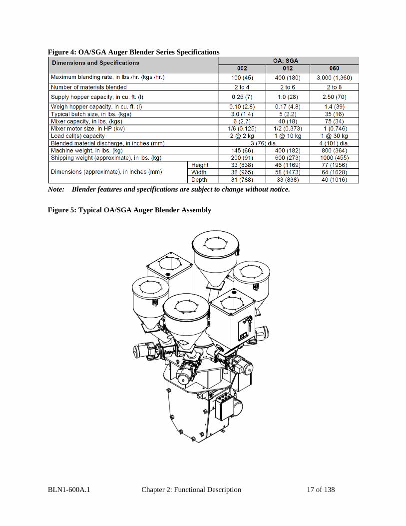
Figure 4: OA/SGA Auger Blender Series Specifications
Note: Blender features and specifications are subject to change without notice.
Figure 5: Typical OA/SGA Auger Blender Assembly
BLN1-600A.1 Chapter 2: Functional Description 18 of 138
2-3 Typical Features and Components
Mechanical Features
Slide Gate Blenders
Exclusive diamond design slide gate metering assemblies meter a large range for free-
flowing pellet materials
Adjustable slide gate stroke limiting restrictors provided for accurate metering of
minor ingredients (not available on 200 models, or removable hopper components)
Removable stainless steel weigh hopper and mixing components
Powder coated mild steel material supply hoppers with machined polycarbonate
cleanout doors and optional material drains (stainless steel hoppers on 200 models)
Precision 0.02% span accurate cantilever load cell weighing system
Compressed air hose with nozzle provided as a convenience for clean-out
Auger Blenders
Efficient Opti-Mixer® (002) and “HC” (012 & 060) mixer designs promote
homogeneity
Precision auger metering (standard on Auger Blenders, optional on Slide Gate
Blenders)
Removable stainless steel mixer agitator and mixer wrap (Opti-Mixer® only)
Both Blender Styles
Precision 1/10% span accurate cantilever load cell weighing system
Safety-interlocked system shuts off compressed air and electricity if mixer is opened
Compressed air hose with nozzle for clean-out
Slide Gate & Auger Blender System Component Description
This section describes the various components of the blending system. The Slide Gate &
Auger blending system is made up of the following components:
Material Supply Hoppers
Slide Gate Metering Assemblies
Auger Metering Assemblies
Weigh Hopper
Weigh Hopper Dump Valve
Mix Chamber
Operator Control Panel
BLN1-600A.1 Chapter 2: Functional Description 19 of 138
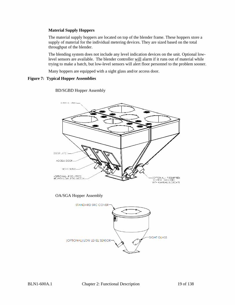
Material Supply Hoppers
The material supply hoppers are located on top of the blender frame. These hoppers store a
supply of material for the individual metering devices. They are sized based on the total
throughput of the blender.
The blending system does not include any level indication devices on the unit. Optional low-
level sensors are available. The blender controller will alarm if it runs out of material while
trying to make a batch, but low-level sensors will alert floor personnel to the problem sooner.
Many hoppers are equipped with a sight glass and/or access door.
Figure 7: Typical Hopper Assemblies
BD/SGBD Hopper Assembly
OA/SGA Hopper Assembly
BLN1-600A.1 Chapter 2: Functional Description 20 of 138
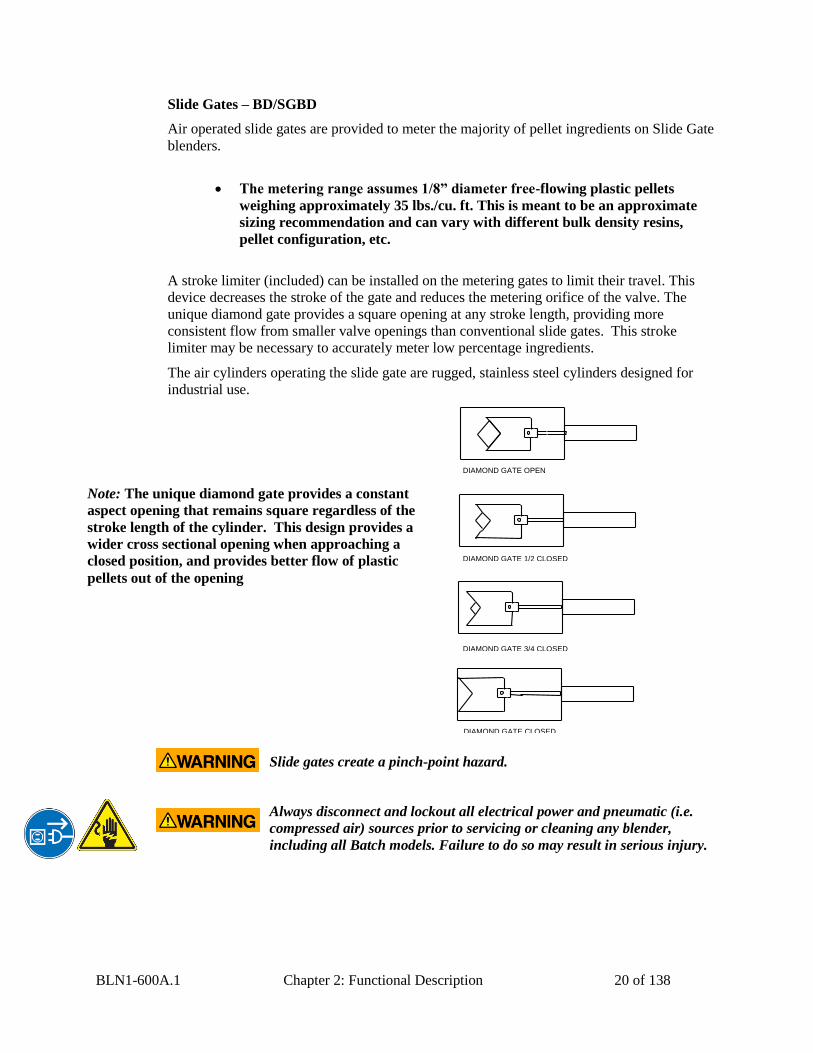
Slide Gates – BD/SGBD
Air operated slide gates are provided to meter the majority of pellet ingredients on Slide Gate
blenders.
A stroke limiter (included) can be installed on the metering gates to limit their travel. This
device decreases the stroke of the gate and reduces the metering orifice of the valve. The
unique diamond gate provides a square opening at any stroke length, providing more
consistent flow from smaller valve openings than conventional slide gates. This stroke
limiter may be necessary to accurately meter low percentage ingredients.
The air cylinders operating the slide gate are rugged, stainless steel cylinders designed for
industrial use.
Slide gates create a pinch-point hazard.
Always disconnect and lockout all electrical power and pneumatic (i.e.
compressed air) sources prior to servicing or cleaning any blender,
including all Batch models. Failure to do so may result in serious injury.
The metering range assumes 1/8” diameter free-flowing plastic pellets
weighing approximately 35 lbs./cu. ft. This is meant to be an approximate
sizing recommendation and can vary with different bulk density resins,
pellet configuration, etc.
DIAMOND GATE CLOSED
DIAMOND GATE 3/4 CLOSED
DIAMOND GATE 1/2 CLOSED
DIAMOND GATE OPEN
Note: The unique diamond gate provides a constant
aspect opening that remains square regardless of the
stroke length of the cylinder. This design provides a
wider cross sectional opening when approaching a
closed position, and provides better flow of plastic
pellets out of the opening
BLN1-600A.1 Chapter 2: Functional Description 21 of 138
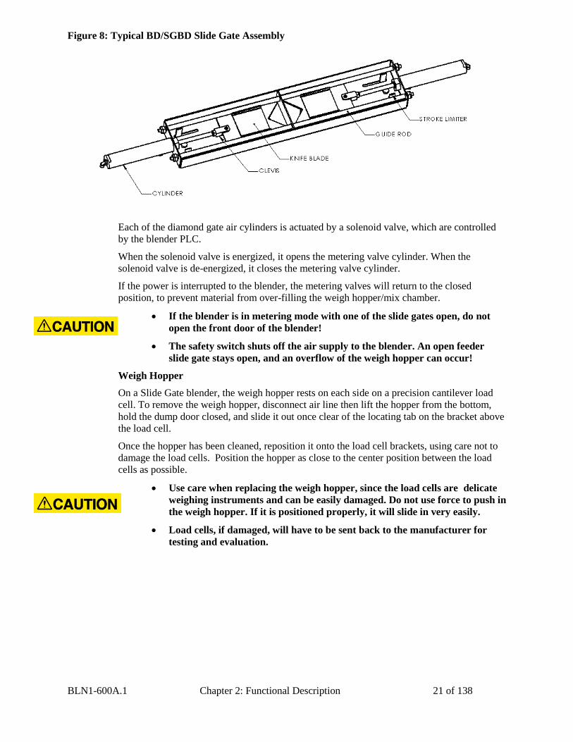
Figure 8: Typical BD/SGBD Slide Gate Assembly
Each of the diamond gate air cylinders is actuated by a solenoid valve, which are controlled
by the blender PLC.
When the solenoid valve is energized, it opens the metering valve cylinder. When the
solenoid valve is de-energized, it closes the metering valve cylinder.
If the power is interrupted to the blender, the metering valves will return to the closed
position, to prevent material from over-filling the weigh hopper/mix chamber.
Weigh Hopper
On a Slide Gate blender, the weigh hopper rests on each side on a precision cantilever load
cell. To remove the weigh hopper, disconnect air line then lift the hopper from the bottom,
hold the dump door closed, and slide it out once clear of the locating tab on the bracket above
the load cell.
Once the hopper has been cleaned, reposition it onto the load cell brackets, using care not to
damage the load cells. Position the hopper as close to the center position between the load
cells as possible.
If the blender is in metering mode with one of the slide gates open, do not
open the front door of the blender!
The safety switch shuts off the air supply to the blender. An open feeder
slide gate stays open, and an overflow of the weigh hopper can occur!
Use care when replacing the weigh hopper, since the load cells are delicate
weighing instruments and can be easily damaged. Do not use force to push in
the weigh hopper. If it is positioned properly, it will slide in very easily.
Load cells, if damaged, will have to be sent back to the manufacturer for
testing and evaluation.
BLN1-600A.1 Chapter 2: Functional Description 22 of 138
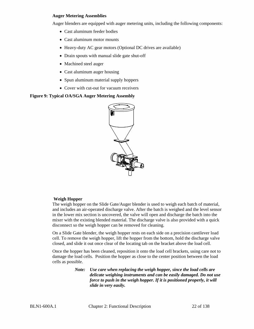
Auger Metering Assemblies
Auger blenders are equipped with auger metering units, including the following components:
Cast aluminum feeder bodies
Cast aluminum motor mounts
Heavy-duty AC gear motors (Optional DC drives are available)
Drain spouts with manual slide gate shut-off
Machined steel auger
Cast aluminum auger housing
Spun aluminum material supply hoppers
Cover with cut-out for vacuum receivers
Figure 9: Typical OA/SGA Auger Metering Assembly
Weigh Hopper
The weigh hopper on the Slide Gate/Auger blender is used to weigh each batch of material,
and includes an air-operated discharge valve. After the batch is weighed and the level sensor
in the lower mix section is uncovered, the valve will open and discharge the batch into the
mixer with the existing blended material. The discharge valve is also provided with a quick
disconnect so the weigh hopper can be removed for cleaning.
On a Slide Gate blender, the weigh hopper rests on each side on a precision cantilever load
cell. To remove the weigh hopper, lift the hopper from the bottom, hold the discharge valve
closed, and slide it out once clear of the locating tab on the bracket above the load cell.
Once the hopper has been cleaned, reposition it onto the load cell brackets, using care not to
damage the load cells. Position the hopper as close to the center position between the load
cells as possible.
Note: Use care when replacing the weigh hopper, since the load cells are
delicate weighing instruments and can be easily damaged. Do not use
force to push in the weigh hopper. If it is positioned properly, it will
slide in very easily.
BLN1-600A.1 Chapter 2: Functional Description 23 of 138
Note: Load cells, if damaged, will have to be sent back to the manufacturer
for testing and evaluation.
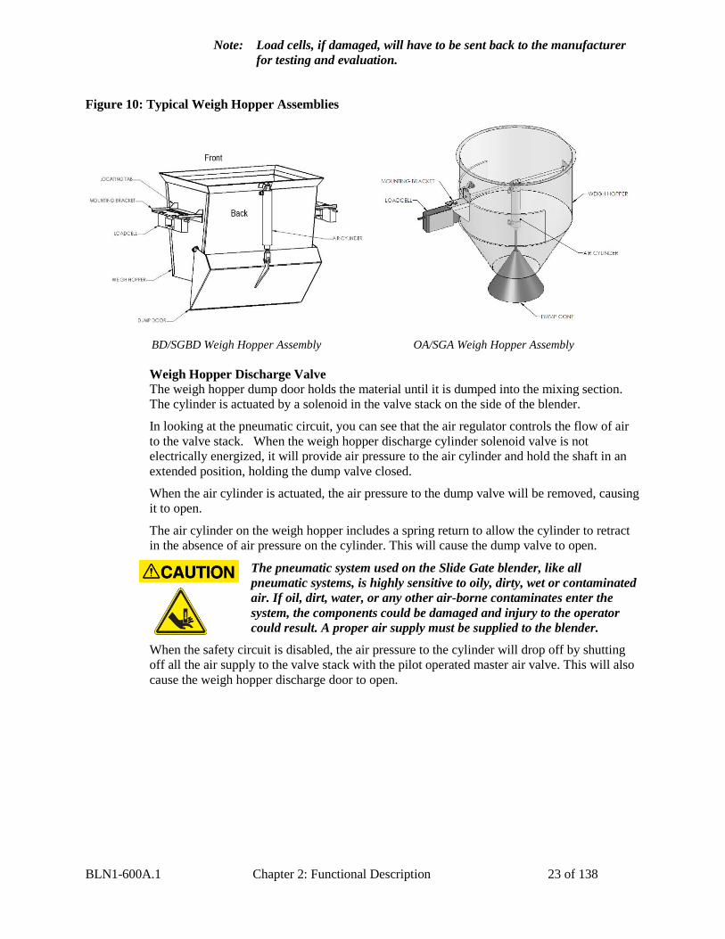
Figure 10: Typical Weigh Hopper Assemblies
BD/SGBD Weigh Hopper Assembly OA/SGA Weigh Hopper Assembly
Weigh Hopper Discharge Valve
The weigh hopper dump door holds the material until it is dumped into the mixing section.
The cylinder is actuated by a solenoid in the valve stack on the side of the blender.
In looking at the pneumatic circuit, you can see that the air regulator controls the flow of air
to the valve stack. When the weigh hopper discharge cylinder solenoid valve is not
electrically energized, it will provide air pressure to the air cylinder and hold the shaft in an
extended position, holding the dump valve closed.
When the air cylinder is actuated, the air pressure to the dump valve will be removed, causing
it to open.
The air cylinder on the weigh hopper includes a spring return to allow the cylinder to retract
in the absence of air pressure on the cylinder. This will cause the dump valve to open.
The pneumatic system used on the Slide Gate blender, like all
pneumatic systems, is highly sensitive to oily, dirty, wet or contaminated
air. If oil, dirt, water, or any other air-borne contaminates enter the
system, the components could be damaged and injury to the operator
could result. A proper air supply must be supplied to the blender.
When the safety circuit is disabled, the air pressure to the cylinder will drop off by shutting
off all the air supply to the valve stack with the pilot operated master air valve. This will also
cause the weigh hopper discharge door to open.
BLN1-600A.1 Chapter 2: Functional Description 24 of 138
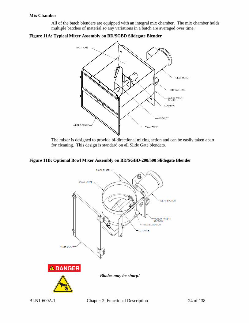
Mix Chamber
All of the batch blenders are equipped with an integral mix chamber. The mix chamber holds
multiple batches of material so any variations in a batch are averaged over time.
Figure 11A: Typical Mixer Assembly on BD/SGBD Slidegate Blender
The mixer is designed to provide bi-directional mixing action and can be easily taken apart
for cleaning. This design is standard on all Slide Gate blenders.
Figure 11B: Optional Bowl Mixer Assembly on BD/SGBD-200/500 Slidegate Blender
Blades may be sharp!
BLN1-600A.1 Chapter 2: Functional Description 25 of 138
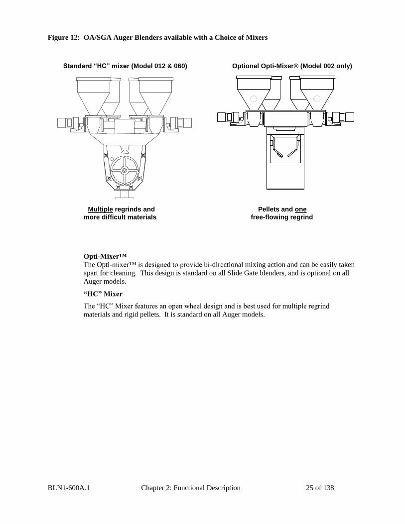
Figure 12: OA/SGA Auger Blenders available with a Choice of Mixers
Standard “HC” mixer (Model 012 & 060) Optional Opti-Mixer® (Model 002 only)
Opti-Mixer™
The Opti-mixer™ is designed to provide bi-directional mixing action and can be easily taken
apart for cleaning. This design is standard on all Slide Gate blenders, and is optional on all
Auger models.
“HC” Mixer
The “HC” Mixer features an open wheel design and is best used for multiple regrind
materials and rigid pellets. It is standard on all Auger models.
Multiple regrinds and Pellets and one
more difficult materials free-flowing regrind
BLN1-600A.1 Chapter 2: Functional Description 26 of 138
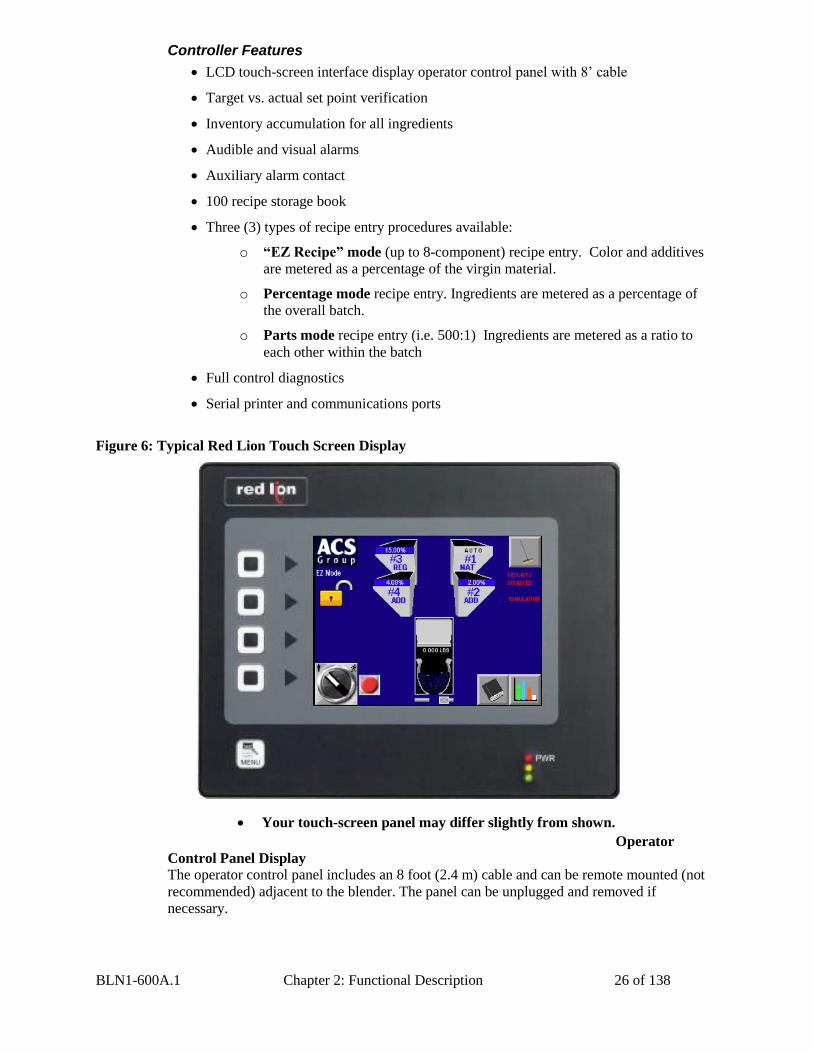
Controller Features
LCD touch-screen interface display operator control panel with 8’ cable
Target vs. actual set point verification
Inventory accumulation for all ingredients
Audible and visual alarms
Auxiliary alarm contact
100 recipe storage book
Three (3) types of recipe entry procedures available:
o “EZ Recipe” mode (up to 8-component) recipe entry. Color and additives
are metered as a percentage of the virgin material.
o Percentage mode recipe entry. Ingredients are metered as a percentage of
the overall batch.
o Parts mode recipe entry (i.e. 500:1) Ingredients are metered as a ratio to
each other within the batch
Full control diagnostics
Serial printer and communications ports
Figure 6: Typical Red Lion Touch Screen Display
Operator
Control Panel Display
The operator control panel includes an 8 foot (2.4 m) cable and can be remote mounted (not
recommended) adjacent to the blender. The panel can be unplugged and removed if
necessary.
Your touch-screen panel may differ slightly from shown.
BLN1-600A.1 Chapter 2: Functional Description 27 of 138
A programmable logic controller (PLC) controls the blender operation. This design provides
excellent blender performance along with an easily replaceable control panel in the unlikely
failure of any computer or electronic part.
The display menu format is very simple. After installation and setup, simply enter in the
recipe and start the blender. See the following pages for controller pushbutton & touchscreen
tags along with typical operator screens.
If it is desired to have a local display and control of the blender closer to a remote operator
station, an optional remote mount operator panel is available.
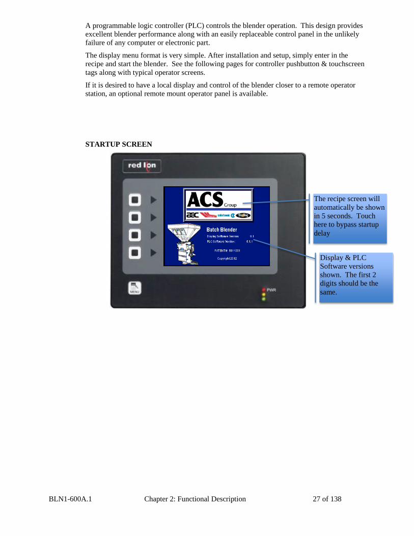
STARTUP SCREEN
The recipe screen will
automatically be shown
in 5 seconds. Touch
here to bypass startup
delay
Display & PLC
Software versions
shown. The first 2
digits should be the
same.
BLN1-600A.1 Chapter 2: Functional Description 28 of 138
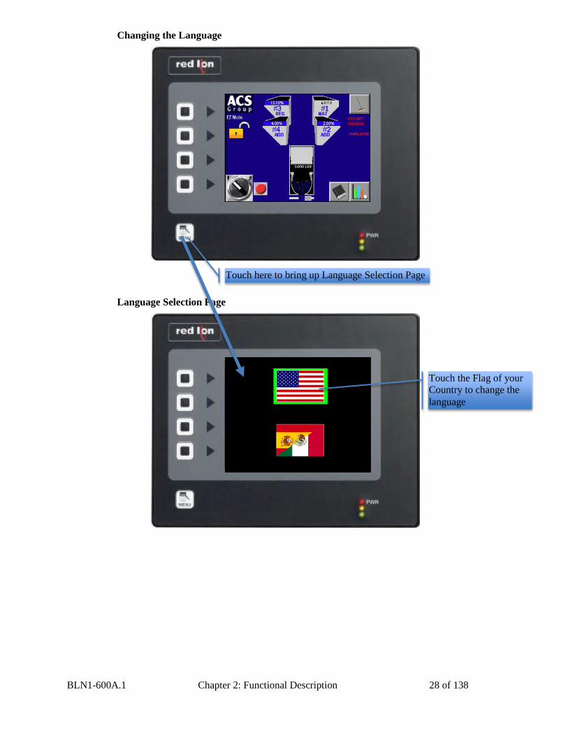
Changing the Language
Language Selection Page
Touch here to bring up Language Selection Page
Touch the Flag of your
Country to change the
language
BLN1-600A.1 Chapter 2: Functional Description 29 of 138
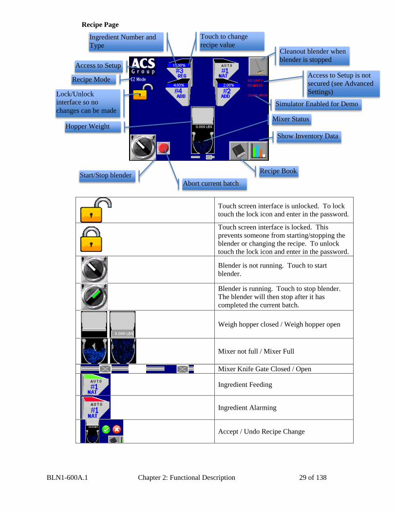
Recipe Page
Touch screen interface is unlocked. To lock
touch the lock icon and enter in the password.
Touch screen interface is locked. This
prevents someone from starting/stopping the
blender or changing the recipe. To unlock
touch the lock icon and enter in the password.
Blender is not running. Touch to start
blender.
Blender is running. Touch to stop blender.
The blender will then stop after it has
completed the current batch.
Weigh hopper closed / Weigh hopper open
Mixer not full / Mixer Full
Mixer Knife Gate Closed / Open
Ingredient Feeding
Ingredient Alarming
Accept / Undo Recipe Change
Cleanout blender when
blender is stopped
Show Inventory Data
Recipe Book
Abort current batch
Start/Stop blender
Lock/Unlock
interface so no
changes can be made
Access to Setup
Touch to change
recipe value
Mixer Status
Recipe Mode Access to Setup is not
secured (see Advanced
Settings)
Simulator Enabled for Demo
Ingredient Number and
Type
Hopper Weight
BLN1-600A.1 Chapter 2: Functional Description 30 of 138
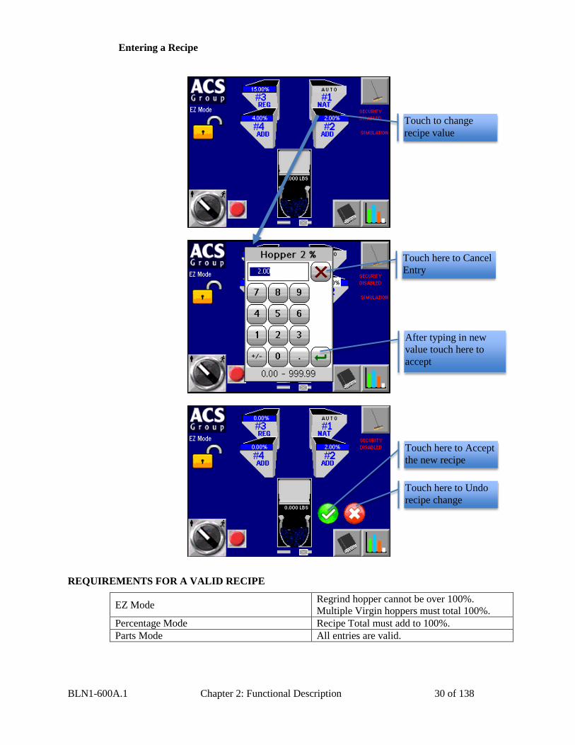
Entering a Recipe
REQUIREMENTS FOR A VALID RECIPE
EZ Mode Regrind hopper cannot be over 100%.
Multiple Virgin hoppers must total 100%.
Percentage Mode Recipe Total must add to 100%.
Parts Mode All entries are valid.
Touch to change
recipe value
After typing in new
value touch here to
accept
Touch here to Cancel
Entry
Touch here to Accept
the new recipe
Touch here to Undo
recipe change
BLN1-600A.1 Chapter 2: Functional Description 31 of 138
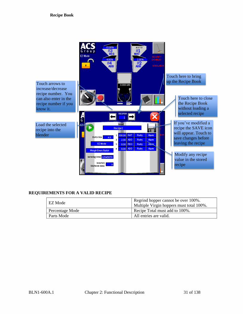
Recipe Book
REQUIREMENTS FOR A VALID RECIPE
EZ Mode Regrind hopper cannot be over 100%.
Multiple Virgin hoppers must total 100%.
Percentage Mode Recipe Total must add to 100%.
Parts Mode All entries are valid.
Touch here to bring
up the Recipe Book
Modify any recipe
value in the stored
recipe
Touch here to close
the Recipe Book
without loading a
selected recipe
Load the selected
recipe into the
blender
Touch arrows to
increase/decrease
recipe number. You
can also enter in the
recipe number if you
know it.
If you’ve modified a
recipe the SAVE icon
will appear. Touch to
save changes before
leaving the recipe
BLN1-600A.1 Chapter 2: Functional Description 32 of 138
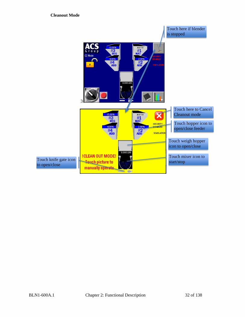
Cleanout Mode
3
Touch here if blender
is stopped
Touch hopper icon to
open/close feeder
Touch weigh hopper
icon to open/close
Touch mixer icon to
start/stop Touch knife gate icon
to open/close
Touch here to Cancel
Cleanout mode
BLN1-600A.1 Chapter 2: Functional Description 33 of 138
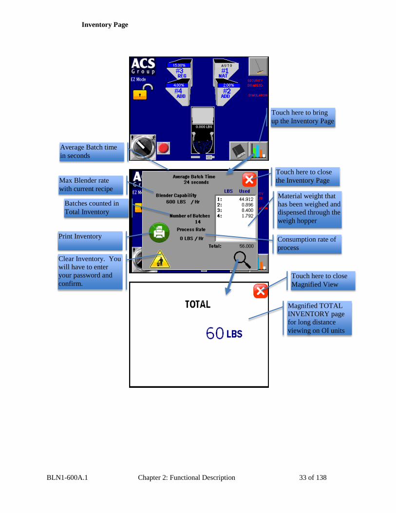
Inventory Page
Touch here to bring
up the Inventory Page
Material weight that
has been weighed and
dispensed through the
weigh hopper
Print Inventory
Magnified TOTAL
INVENTORY page
for long distance
viewing on OI units
Clear Inventory. You
will have to enter
your password and
confirm.
Touch here to close
the Inventory Page
Batches counted in
Total Inventory
Max Blender rate
with current recipe
Average Batch time
in seconds
Consumption rate of
process
Touch here to close
Magnified View
BLN1-600A.1 Chapter 2: Functional Description 34 of 138
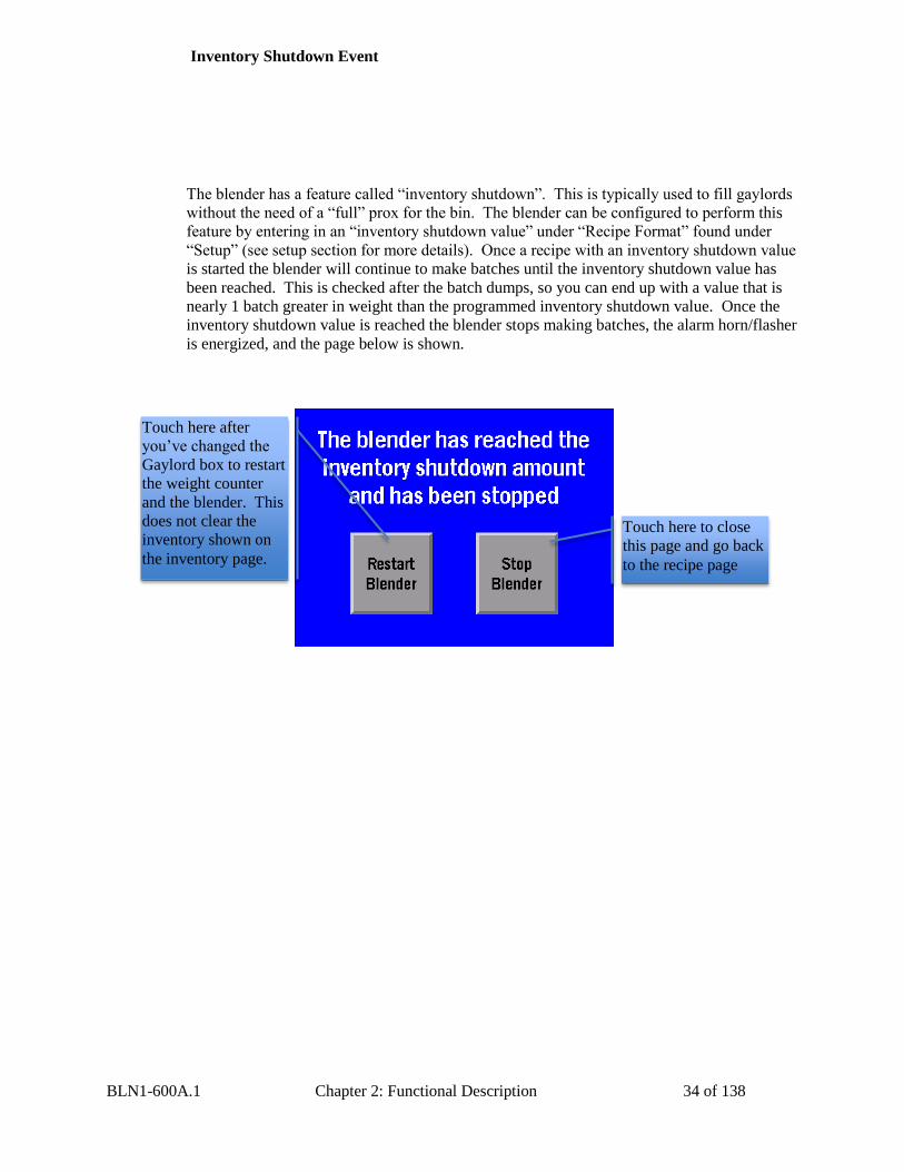
Inventory Shutdown Event
The blender has a feature called “inventory shutdown”. This is typically used to fill gaylords
without the need of a “full” prox for the bin. The blender can be configured to perform this
feature by entering in an “inventory shutdown value” under “Recipe Format” found under
“Setup” (see setup section for more details). Once a recipe with an inventory shutdown value
is started the blender will continue to make batches until the inventory shutdown value has
been reached. This is checked after the batch dumps, so you can end up with a value that is
nearly 1 batch greater in weight than the programmed inventory shutdown value. Once the
inventory shutdown value is reached the blender stops making batches, the alarm horn/flasher
is energized, and the page below is shown.
Touch here to close
this page and go back
to the recipe page
Touch here after
you’ve changed the
Gaylord box to restart
the weight counter
and the blender. This
does not clear the
inventory shown on
the inventory page.
BLN1-600A.1 Chapter 2: Functional Description 35 of 138
2-4 Optional Components The following is a list of options, which your blender may have been equipped with:
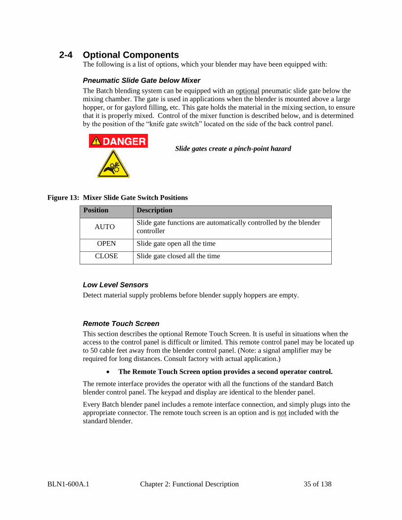
Pneumatic Slide Gate below Mixer
The Batch blending system can be equipped with an optional pneumatic slide gate below the
mixing chamber. The gate is used in applications when the blender is mounted above a large
hopper, or for gaylord filling, etc. This gate holds the material in the mixing section, to ensure
that it is properly mixed. Control of the mixer function is described below, and is determined
by the position of the “knife gate switch” located on the side of the back control panel.
Slide gates create a pinch-point hazard
Figure 13: Mixer Slide Gate Switch Positions
Position Description
AUTO Slide gate functions are automatically controlled by the blender
controller
OPEN Slide gate open all the time
CLOSE Slide gate closed all the time
Low Level Sensors
Detect material supply problems before blender supply hoppers are empty.
Remote Touch Screen
This section describes the optional Remote Touch Screen. It is useful in situations when the
access to the control panel is difficult or limited. This remote control panel may be located up
to 50 cable feet away from the blender control panel. (Note: a signal amplifier may be
required for long distances. Consult factory with actual application.)
The remote interface provides the operator with all the functions of the standard Batch
blender control panel. The keypad and display are identical to the blender panel.
Every Batch blender panel includes a remote interface connection, and simply plugs into the
appropriate connector. The remote touch screen is an option and is not included with the
standard blender.
The Remote Touch Screen option provides a second operator control.
BLN1-600A.1 Chapter 2: Functional Description 36 of 138
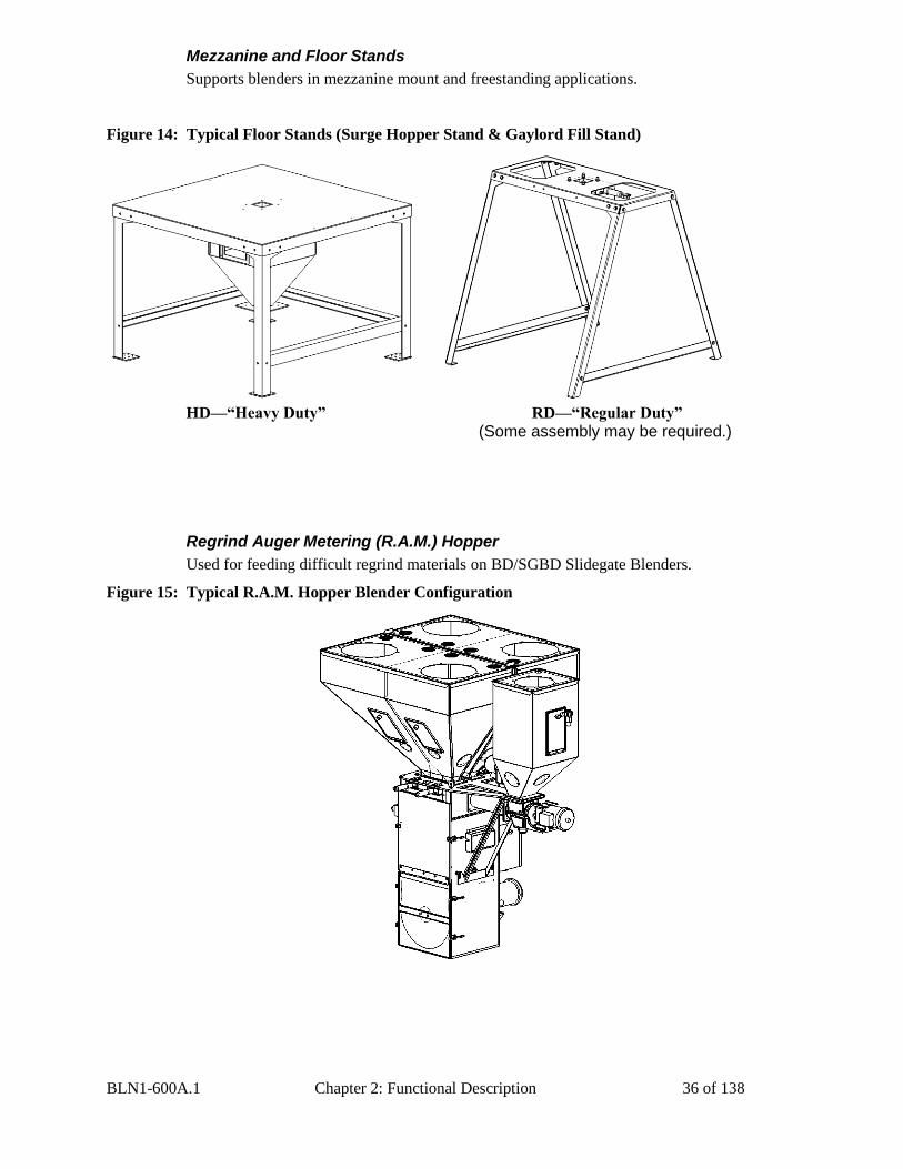
Mezzanine and Floor Stands
Supports blenders in mezzanine mount and freestanding applications.
Figure 14: Typical Floor Stands (Surge Hopper Stand & Gaylord Fill Stand)
HD—“Heavy Duty” RD—“Regular Duty”
(Some assembly may be required.)
Regrind Auger Metering (R.A.M.) Hopper
Used for feeding difficult regrind materials on BD/SGBD Slidegate Blenders.
Figure 15: Typical R.A.M. Hopper Blender Configuration
BLN1-600A.1 Chapter 2: Functional Description 37 of 138
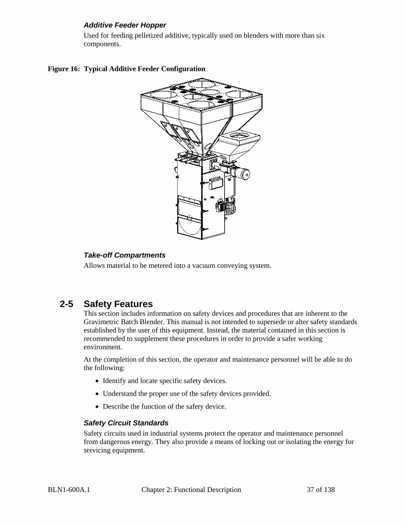
Additive Feeder Hopper
Used for feeding pelletized additive, typically used on blenders with more than six
components.
Figure 16: Typical Additive Feeder Configuration
Take-off Compartments
Allows material to be metered into a vacuum conveying system.
2-5 Safety Features This section includes information on safety devices and procedures that are inherent to the
Gravimetric Batch Blender. This manual is not intended to supersede or alter safety standards
established by the user of this equipment. Instead, the material contained in this section is
recommended to supplement these procedures in order to provide a safer working
environment.
At the completion of this section, the operator and maintenance personnel will be able to do
the following:
Identify and locate specific safety devices.
Understand the proper use of the safety devices provided.
Describe the function of the safety device.
Safety Circuit Standards
Safety circuits used in industrial systems protect the operator and maintenance personnel
from dangerous energy. They also provide a means of locking out or isolating the energy for
servicing equipment.
BLN1-600A.1 Chapter 2: Functional Description 38 of 138
Various agencies have contributed to the establishment of safety standards that apply to the
design and manufacture of automated equipment. The Occupational Safety and Health
Administration (OSHA) article 1910.147 and NFPA 70 and 79 are just a few of the
organizations that have joined with the plastics industry to develop safety standards.
Every effort has been made to incorporate these standards into the design of the Batch
Blender; however, it is the responsibility of the personnel operating and maintaining the
equipment to familiarize themselves with the safety procedures and the proper use of any
safety devices.
Fail Safe Operation
If a safety device or circuit should fail, the design must be such that the failure causes a
“Safe” condition. As an example, a safety switch must be a normally open switch. The switch
must be held closed with the device it is to protect. If the switch fails, it will go to the open
condition, tripping out the safety circuit.
At no time should the safety device fail and allow the operation to continue. For
example, if a safety switch is guarding a motor, and the safety switch fails, the motor should
not be able to run.
Safety Device Lock-Outs
Some safety devices disconnect electrical energy from a circuit. The safety devices that are
used on the Batch Blenders are primarily concerned with pneumatic and electrical power
disconnection and the disabling of moving parts that may need to be accessed during the
normal operation of the machine.
Some of the safety devices utilize a manual activator. This is the method of initiating the
safety lock out. This may be in the form of a plug, lever or a handle. Within this lockable
handle, there may be a location for a padlock. Personnel servicing the equipment should
place a padlock in the lockout handle.
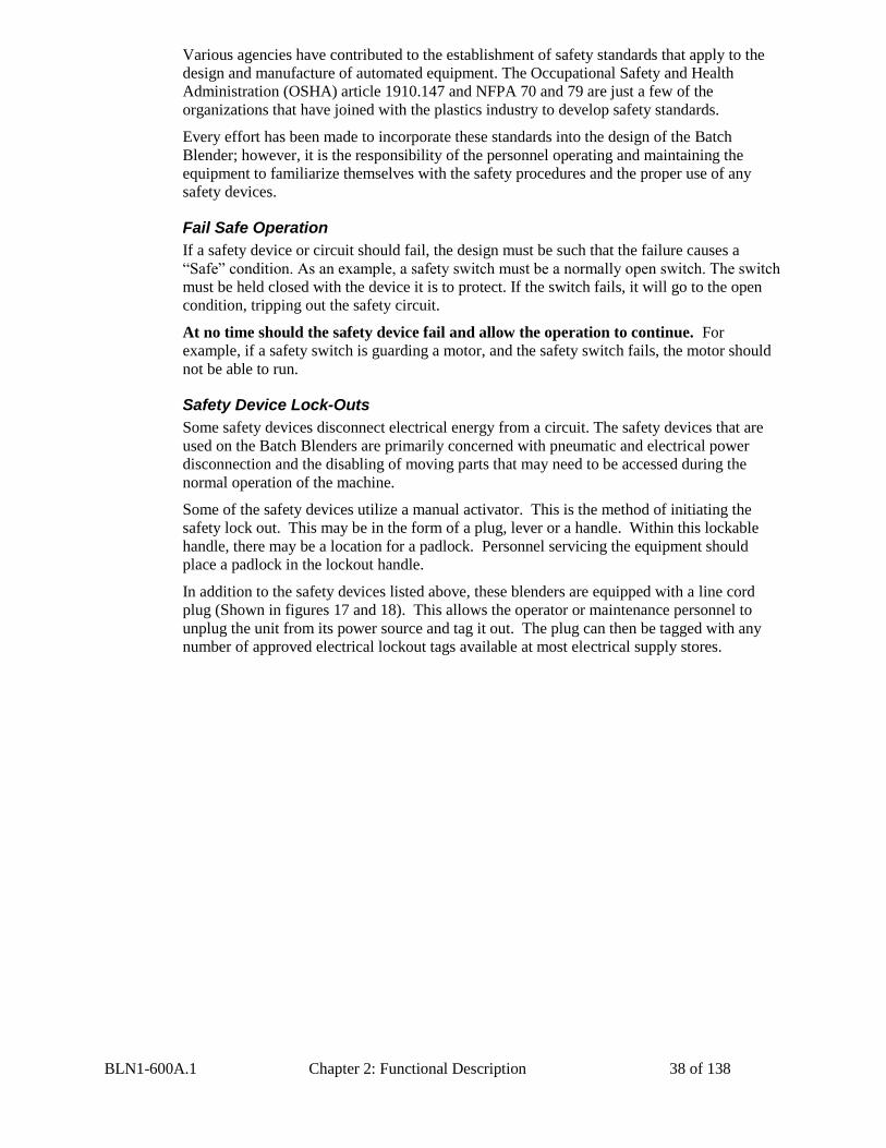
In addition to the safety devices listed above, these blenders are equipped with a line cord
plug (Shown in figures 17 and 18). This allows the operator or maintenance personnel to
unplug the unit from its power source and tag it out. The plug can then be tagged with any
number of approved electrical lockout tags available at most electrical supply stores.
BLN1-600A.1 Chapter 2: Functional Description 39 of 138
Figure 17: Electrical Disconnect Plug
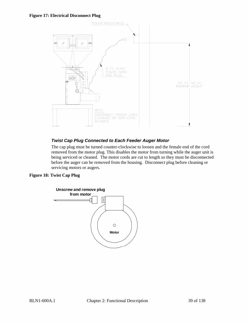
Twist Cap Plug Connected to Each Feeder Auger Motor
The cap plug must be turned counter-clockwise to loosen and the female end of the cord
removed from the motor plug. This disables the motor from turning while the auger unit is
being serviced or cleaned. The motor cords are cut to length so they must be disconnected
before the auger can be removed from the housing. Disconnect plug before cleaning or
servicing motors or augers.
Figure 18: Twist Cap Plug
Motor
Unscrew and remove plug from motor
BLN1-600A.1 Chapter 2: Functional Description 40 of 138
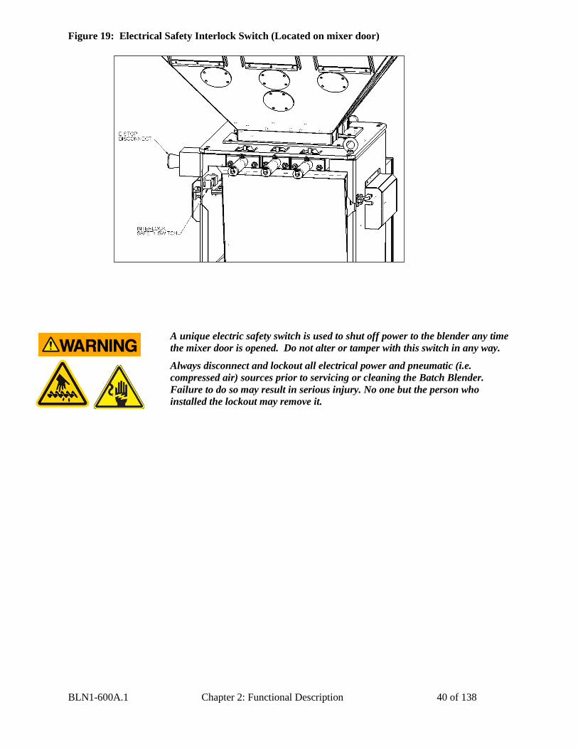
Figure 19: Electrical Safety Interlock Switch (Located on mixer door)
A unique electric safety switch is used to shut off power to the blender any time
the mixer door is opened. Do not alter or tamper with this switch in any way.
Always disconnect and lockout all electrical power and pneumatic (i.e.
compressed air) sources prior to servicing or cleaning the Batch Blender.
Failure to do so may result in serious injury. No one but the person who
installed the lockout may remove it.
BLN1-600A.1 Chapter 3: Installation 41 of 138
Chapter 3: Installation
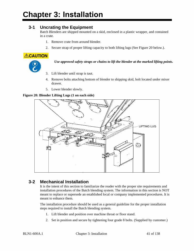
3-1 Uncrating the Equipment Batch Blenders are shipped mounted on a skid, enclosed in a plastic wrapper, and contained
in a crate.
1. Remove crate from around blender.
2. Secure strap of proper lifting capacity to both lifting lugs (See Figure 20 below.).
Use approved safety straps or chains to lift the blender at the marked lifting points.
3. Lift blender until strap is taut.
4. Remove bolts attaching bottom of blender to shipping skid, bolt located under mixer
drawer.
5. Lower blender slowly.
Figure 20: Blender Lifting Lugs (1 on each side)
3-2 Mechanical Installation It is the intent of this section to familiarize the reader with the proper site requirements and
installation procedures of the Batch blending system. The information in this section is NOT
meant to replace or supersede an established local or company implemented procedures. It is
meant to enhance them.
The installation procedure should be used as a general guideline for the proper installation
steps required to install the Batch blending system.
1. Lift blender and position over machine throat or floor stand.
2. Set in position and secure by tightening four grade 8 bolts. (Supplied by customer.)
BLN1-600A.1 Chapter 3: Installation 42 of 138
3. Remove lifting strap.
4. If equipped; adjust the four leveling bolts on the floor stand blender support rails.
5. Mount the material conveying system receivers on the top of the blender supply
hoppers.
6. Align the weigh hopper on the load cell brackets with air cylinder toward rear of
blender. Carefully adjust the load cell brackets to ensure that the weigh hopper is
centered on the brackets without rocking. If for some reason the locating tabs do not
align with the weigh hopper, they can easily be loosened and adjusted.
7. Check the slide gate metering assemblies to ensure they are not damaged, and will
slide back and forth freely. These are the most important items on the blender,
besides the load cell and weigh hopper assemblies.
Site Requirements
This section describes site requirements in detail. These requirements are broken down into
mechanical mounting, electrical connections and pneumatic connections. Since the Slide Gate
Blender is available in several different mounting arrangements, it is necessary for the reader
to become familiar with the different arrangements.
Mounting Configurations
The Slide Gate Blending System is available in (3) three basic mounting arrangements. They
are:
Machine Mount
Mezzanine Mount
Floor Mount
Machine Mount
In a machine mounting application of the Slide Gate unit, there are a few items to review
before placement and mounting of the blending system begins.
First, verify the machine flange dimensions match the Slide Gate blender flange (if the
optional pre-drilled holes were ordered). The Slide Gate blender can also be equipped with an
optional cast throat section with a drain port. This will bolt under the bottom plate of the
blender.
Verify that the machine throat is physically capable of supporting the Slide Gate blending
system with a full load of material and vacuum loading equipment installed.
While in operation, the slide gate blender applies horizontal and vertical
pressures to the mounting flange. If there is a question as to the mechanical
stability of a mounting flange, contact the manufacturer’s engineering
department.
Verify all clearances on the top and beside the processing machine. This is to insure that all
motors, hoppers, control panels, etc. have adequate room for proper operation and servicing.
Refer to the assembly drawing with the unit for actual height and width dimensions.
Use extreme care when tightening bolts on top of the load cells so you do not
spring the load cells. The load cells are extremely delicate and should be
treated with care!
BLN1-600A.1 Chapter 3: Installation 43 of 138
Allow at least 36” clearance around blender to provide adequate room for
cleaning, servicing, etc.
Using proper lifting equipment, lift the blender, using the lifting lugs attached to the top plate
of the blender. These lifting lugs can also be used to fasten horizontal or angled braces to the
blender if more stability is needed.
Larger blenders need to be braced as part of the installation. Take care to insure
proper orientation with adequate access to operator controls, mix chamber, and
metering units
Never weld on the blender, support stand, machine or mezzanine without first
removing the control panel and verifying that the blender is properly grounded.
Mezzanine Mount
In a mezzanine mount application, review the following items before installation begins.
First, verify the Batch mounting locations match the mezzanine supports. Verify that the
mezzanine is capable of supporting the blender with a full load of material and vacuum
loading equipment installed.
While in operation, the batch blender applies horizontal and vertical pressures
to the mounting flange. If there is a question as to the mechanical stability of a
mounting flange, contact the manufacturer’s mechanical engineering
department.
Ensure that the gravity feed tube is installed in a vertical position, so that the materials will
gravity flow to the extruder hopper. Use aluminum tubing or smooth wall flex hose.
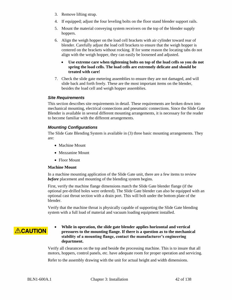
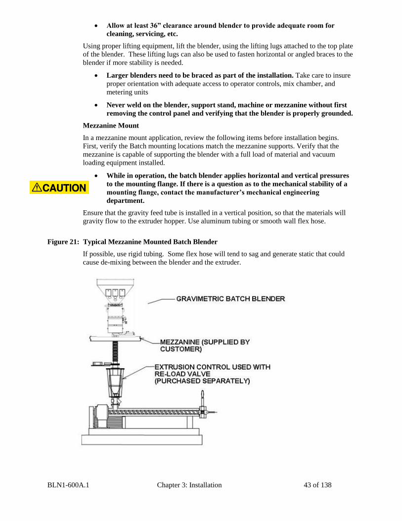
Figure 21: Typical Mezzanine Mounted Batch Blender
If possible, use rigid tubing. Some flex hose will tend to sag and generate static that could
cause de-mixing between the blender and the extruder.
BLN1-600A.1 Chapter 3: Installation 44 of 138
Make sure that adequate space is around the blender (36” recommended) to allow proper
cleaning, servicing, etc.
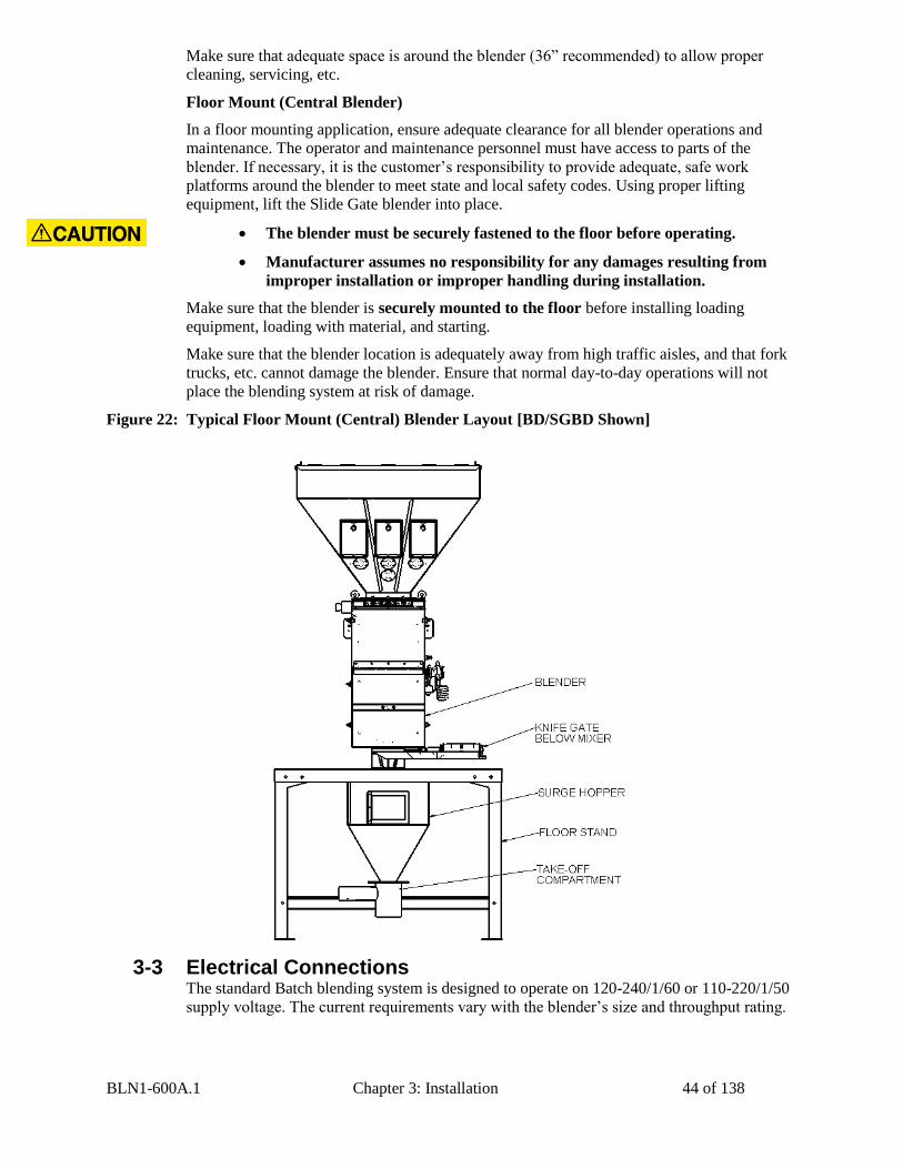
Floor Mount (Central Blender)
In a floor mounting application, ensure adequate clearance for all blender operations and
maintenance. The operator and maintenance personnel must have access to parts of the
blender. If necessary, it is the customer’s responsibility to provide adequate, safe work
platforms around the blender to meet state and local safety codes. Using proper lifting
equipment, lift the Slide Gate blender into place.
Make sure that the blender is securely mounted to the floor before installing loading
equipment, loading with material, and starting.
Make sure that the blender location is adequately away from high traffic aisles, and that fork
trucks, etc. cannot damage the blender. Ensure that normal day-to-day operations will not
place the blending system at risk of damage.
Figure 22: Typical Floor Mount (Central) Blender Layout [BD/SGBD Shown]
3-3 Electrical Connections The standard Batch blending system is designed to operate on 120-240/1/60 or 110-220/1/50
supply voltage. The current requirements vary with the blender’s size and throughput rating.
The blender must be securely fastened to the floor before operating.
Manufacturer assumes no responsibility for any damages resulting from
improper installation or improper handling during installation.

BLN1-600A.1 Chapter 3: Installation 45 of 138
For exact current requirements, check the blender serial number tag, located on the rear plate
of the mixer section.
If a step down transformer was provided, it should never be used to power anything other
than the blender. Loading equipment, etc. must be powered by another power source. As well
as possibly overloading the transformer, the additional equipment may induce power line
noise that may affect the operation of the blending system.
The transformer will be mounted and wired by the customer or your installer. If company or
local codes require fusing or disconnects, these items must be supplied, wired, and mounted
by the customer.
1. Provide a correctly sized and protected power supply to the unit.
2. If an electrical supply disconnect is not installed as a factory option, the customer is responsible to properly size and install a suitable disconnect.
3. Refer to National Electric Code (NEC) 430-24-26 for proper feed conductor and supply disconnect sizing.
4. Voltages must be within plus or minus ten percent (±10%) of the nameplate rating.
5. Maintain a safe ground and disconnect the power supply before servicing the unit (NFPA Article 250).
A qualified electrician should make electrical connections and disconnect the electricity when service calls are needed.
Improper electrical connections can damage the unit and cause serious operator injury or death!
MAKE SURE THAT ALL ELECTRICAL CONNECTIONS ARE MADE BY A QUALIFIED ELECTRICIAN, AND THAT ALL CONNECTIONS ARE TIGHT.
Each blending system MUST be connected to a separate source of power. Do
not connect other electrical equipment, especially self-contained hopper
loaders, on the same line as the blending system.
BLN1-600A.1 Chapter 3: Installation 46 of 138
Ensure that the power entrance location on the blender panel remains unchanged. Make sure
that the proper size wire and proper wire routing techniques are used when installing the
supply wiring to the control panel. Care must be taken to ensure that the supply wiring does
not interfere with the low voltage DC wiring.
The blender is equipped with a plug that functions as the disconnect device (See Figure 19 on
Page 27 for an example). The mating receptacle must be installed no higher than 5’ feet
(1.6 m) above the floor. Make sure your installation conforms to your regional electrical
standards.
3-4 Pneumatic Connections The Batch blending system uses plant-supplied compressed air to operate the metering and
dump valves on the blender.
CLEAN AND DRY air must be supplied to the blender. The air supply should be filtered
through a 5 micron air filter with a water separator. Oil should not be used unless air dryers
are installed on the compressed air supply. In this situation, an oiler may be required on the
blender to keep the air cylinder seals lubricated.
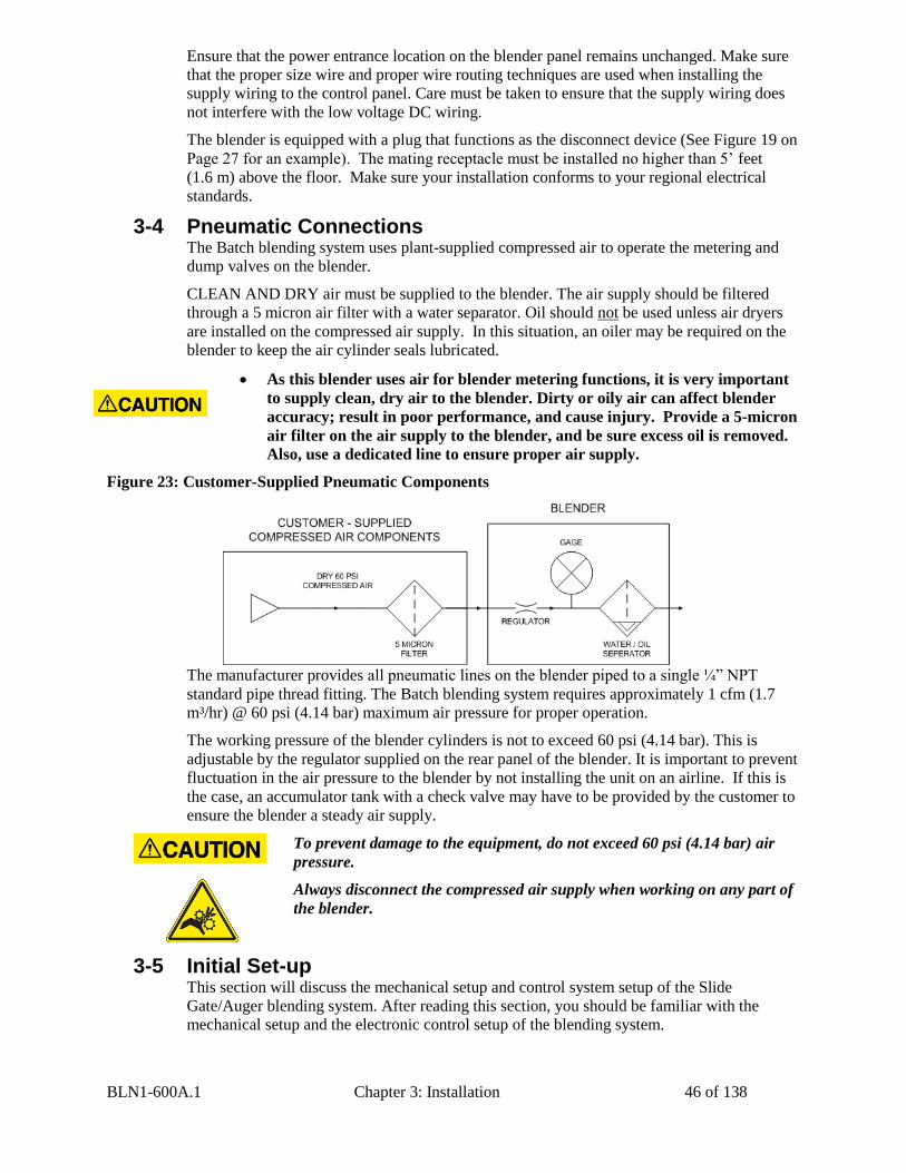
Figure 23: Customer-Supplied Pneumatic Components
The manufacturer provides all pneumatic lines on the blender piped to a single ¼” NPT
standard pipe thread fitting. The Batch blending system requires approximately 1 cfm (1.7
m³/hr) @ 60 psi (4.14 bar) maximum air pressure for proper operation.
The working pressure of the blender cylinders is not to exceed 60 psi (4.14 bar). This is
adjustable by the regulator supplied on the rear panel of the blender. It is important to prevent
fluctuation in the air pressure to the blender by not installing the unit on an airline. If this is
the case, an accumulator tank with a check valve may have to be provided by the customer to
ensure the blender a steady air supply.
To prevent damage to the equipment, do not exceed 60 psi (4.14 bar) air
pressure.
Always disconnect the compressed air supply when working on any part of
the blender.
3-5 Initial Set-up This section will discuss the mechanical setup and control system setup of the Slide
Gate/Auger blending system. After reading this section, you should be familiar with the
mechanical setup and the electronic control setup of the blending system.
As this blender uses air for blender metering functions, it is very important
to supply clean, dry air to the blender. Dirty or oily air can affect blender
accuracy; result in poor performance, and cause injury. Provide a 5-micron
air filter on the air supply to the blender, and be sure excess oil is removed.
Also, use a dedicated line to ensure proper air supply.
BLN1-600A.1 Chapter 3: Installation 47 of 138
Mechanical Set-up
Stroke Limiters for Metering Gates
Stroke limiters are supplied on components 1 through 6 with all Slide Gate blenders to allow
standard metering gates to meter small amounts of low percentage additive materials.
Generally, the stroke limiter is not required on major ingredients (usually number 1 and 3)
and should be adjusted to the rear-most position. If they are used on components number 1
and 3 the throughput of the blender will be reduced.
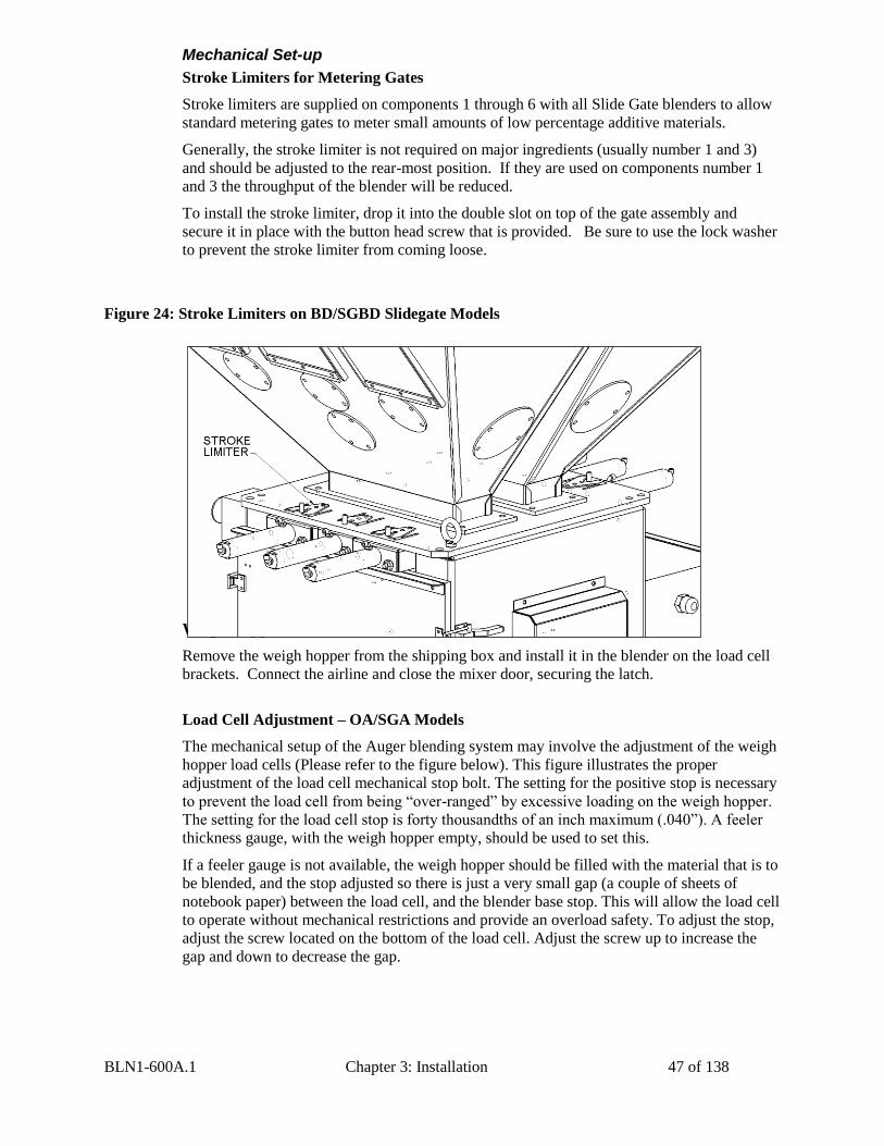
To install the stroke limiter, drop it into the double slot on top of the gate assembly and
secure it in place with the button head screw that is provided. Be sure to use the lock washer
to prevent the stroke limiter from coming loose.
Figure 24: Stroke Limiters on BD/SGBD Slidegate Models
Weigh Hopper Installation
Remove the weigh hopper from the shipping box and install it in the blender on the load cell
brackets. Connect the airline and close the mixer door, securing the latch.
Load Cell Adjustment – OA/SGA Models
The mechanical setup of the Auger blending system may involve the adjustment of the weigh
hopper load cells (Please refer to the figure below). This figure illustrates the proper
adjustment of the load cell mechanical stop bolt. The setting for the positive stop is necessary
to prevent the load cell from being “over-ranged” by excessive loading on the weigh hopper.
The setting for the load cell stop is forty thousandths of an inch maximum (.040”). A feeler
thickness gauge, with the weigh hopper empty, should be used to set this.
If a feeler gauge is not available, the weigh hopper should be filled with the material that is to
be blended, and the stop adjusted so there is just a very small gap (a couple of sheets of
notebook paper) between the load cell, and the blender base stop. This will allow the load cell
to operate without mechanical restrictions and provide an overload safety. To adjust the stop,
adjust the screw located on the bottom of the load cell. Adjust the screw up to increase the
gap and down to decrease the gap.
BLN1-600A.1 Chapter 3: Installation 48 of 138
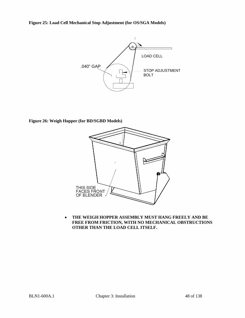
Figure 25: Load Cell Mechanical Stop Adjustment (for OS/SGA Models)
LOAD CELL
.040" GAPSTOP ADJUSTMENTBOLT
Figure 26: Weigh Hopper (for BD/SGBD Models)
THE WEIGH HOPPER ASSEMBLY MUST HANG FREELY AND BE
FREE FROM FRICTION, WITH NO MECHANICAL OBSTRUCTIONS
OTHER THAN THE LOAD CELL ITSELF.
BLN1-600A.1 Chapter 3: Installation 49 of 138
Final Connections
Connect the blender to the appropriate power source.
Connect the compressed air piping, ensuring that a 5-micron air filter is installed, along with
the proper water trap, and lubrication unit, if required. Verify that 60 psi (4.14 bar) of clean,
dry compressed air is supplied to the blender.
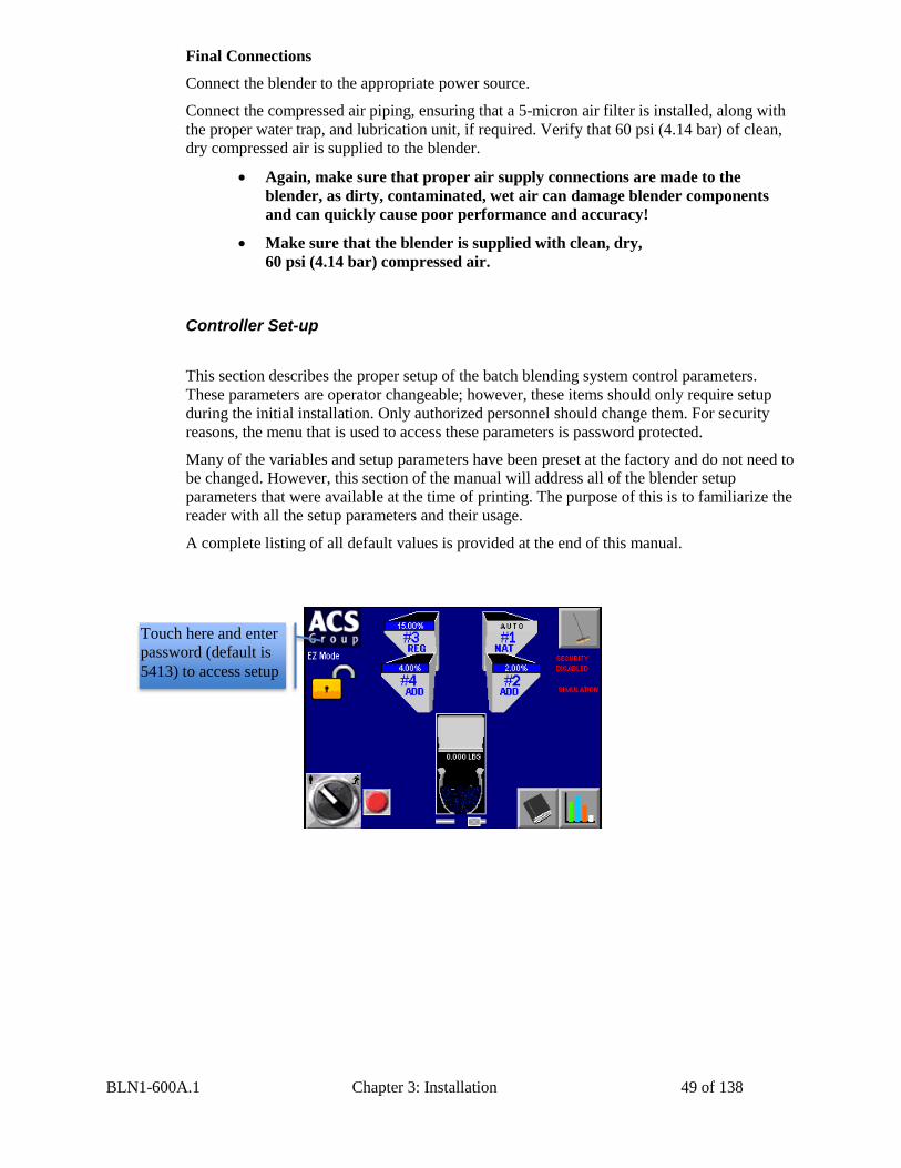
Controller Set-up
This section describes the proper setup of the batch blending system control parameters.
These parameters are operator changeable; however, these items should only require setup
during the initial installation. Only authorized personnel should change them. For security
reasons, the menu that is used to access these parameters is password protected.
Many of the variables and setup parameters have been preset at the factory and do not need to
be changed. However, this section of the manual will address all of the blender setup
parameters that were available at the time of printing. The purpose of this is to familiarize the
reader with all the setup parameters and their usage.
A complete listing of all default values is provided at the end of this manual.
Again, make sure that proper air supply connections are made to the
blender, as dirty, contaminated, wet air can damage blender components
and can quickly cause poor performance and accuracy!
Make sure that the blender is supplied with clean, dry,
60 psi (4.14 bar) compressed air.
Touch here and enter
password (default is
5413) to access setup
BLN1-600A.1 Chapter 3: Installation 50 of 138
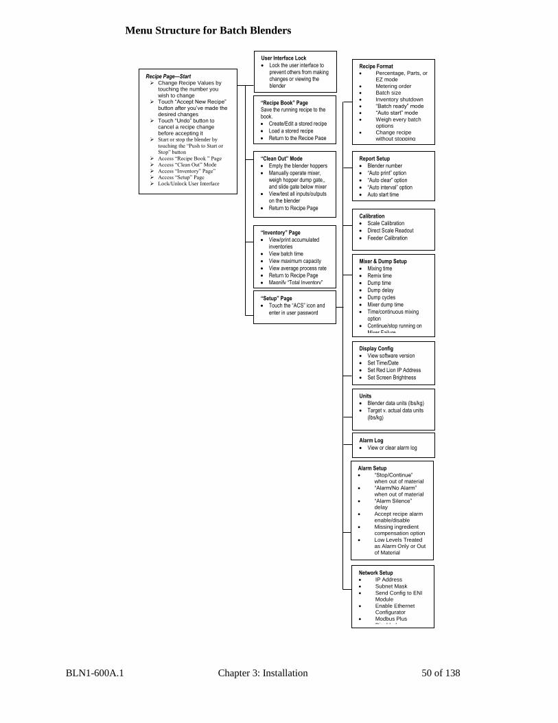
Menu Structure for Batch Blenders
Recipe Page—Start Change Recipe Values by
touching the number you wish to change
Touch “Accept New Recipe” button after you’ve made the desired changes
Touch “Undo” button to cancel a recipe change before accepting it
Start or stop the blender by
touching the “Push to Start or
Stop” button
Access “Recipe Book ” Page
Access “Clean Out” Mode
Access “Inventory” Page”
Access “Setup” Page
Lock/Unlock User Interface
“Recipe Book” Page Save the running recipe to the book.
Create/Edit a stored recipe
Load a stored recipe
Return to the Recipe Page
“Clean Out” Mode
Empty the blender hoppers
Manually operate mixer, weigh hopper dump gate,, and slide gate below mixer
View/test all inputs/outputs on the blender
Return to Recipe Page
“Inventory” Page
View/print accumulated inventories
View batch time
View maximum capacity
View average process rate
Return to Recipe Page
Magnify “Total Inventory”
“Setup” Page
Touch the “ACS” icon and
enter in user password
Recipe Format Percentage, Parts, or
EZ mode
Metering order
Batch size
Inventory shutdown
“Batch ready” mode
“Auto start” mode
Weigh every batch options
Change recipe without stopping
Report Setup
Blender number
“Auto print” option
“Auto clear” option
“Auto interval” option
Auto start time
Calibration
Scale Calibration
Direct Scale Readout
Feeder Calibration
Mixer & Dump Setup
Mixing time
Remix time
Dump time
Dump delay
Dump cycles
Mixer dump time
Time/continuous mixing option
Continue/stop running on Mixer Failure
Display Config
View software version
Set Time/Date
Set Red Lion IP Address
Set Screen Brightness
Units
Blender data units (lbs/kg)
Target v. actual data units
(lbs/kg)
Alarm Log
View or clear alarm log
Alarm Setup “Stop/Continue”
when out of material
“Alarm/No Alarm” when out of material
“Alarm Silence” delay
Accept recipe alarm enable/disable
Missing ingredient compensation option
Low Levels Treated as Alarm Only or Out
of Material
Network Setup IP Address
Subnet Mask
Send Config to ENI Module
Enable Ethernet Configurator
Modbus Plus Disabled
User Interface Lock
Lock the user interface to prevent others from making changes or viewing the blender
BLN1-600A.1 Chapter 3: Installation 51 of 138
Blender Calibration
The load cells on the blender are FACTORY CALIBRATED. Since the load cells can be
subject to shock loading during shipping, moving, etc., we recommend that they be
recalibrated.
The load cells monitor the weight of each ingredient added to the blender weigh hopper.
Since load cells are reading the actual material weight that is metered by the feeders, the
proper calibration of these load cells is essential for the correct operation of the blender.
The load cells should be checked once a month with a calibration weight and if
necessary recalibrated to ensure that they have not been damaged in the normal routine
of removing and replacing the weigh hopper for cleaning, color changes, etc.
The calibration of each load cell is accomplished by using two reference points on the output
of the load cell scale. The first of these points is known as the “Tare Weight”. This is the
weight of the empty hopper assembly on the load cell. This is also known as the zero weight
point (starting point) of the scale. This zero or starting point must be initialized with an empty
weigh hopper. There must be no binding or leverage put on the load cell.
The second weight point used in the load cell calibration procedure is a known amount of
weight for the weigh hopper. A calibration weight is provided with all Batch blending
systems. The calibration weight is stamped with its actual weight on top. If this is not
available, any object with a known weight accurate +/- 0.01 lbs. will suffice. (The weight
should be as close as possible to the maximum batch size you plan to run.) The weight will
be in pounds, unless the blender is provided for metric operation. In the case of a metric
blender display, the weight to be used is calibrated in kilograms.
Given the two weight points on the load cell scale, the controller should determine any other
weight on the load cell span. This is limited to the maximum capacity of the load cell. The
standard load cell used on these blenders has a span accuracy of 0.02%.
The maximum capacity of each load cell is clearly marked on top of the load cell. This value
will be indicated in kilograms (1 kg = 2.2 lbs.).
The weight scale on a new blender comes pre-calibrated, but it is
recommended to periodically check the calibration to ensure that the
reported inventory levels are accurate.

BLN1-600A.1 Chapter 3: Installation 52 of 138
Verify Weigh Hopper (Load Cell) Calibration
Verifying Calibration (Recommended on a periodic basis to ensure accuracy)
1. The blender must be stopped before this can be done.
2. From the Setup Menu touch “Calibration” and then “Direct Scale Readout”.
3. Remove the weigh hopper.
4. Locate the weight display for each of the two load cells. Write down the displayed
value.
5. Add the calibration weight to each load cell mounting bracket and write down the
value displayed in “weight”, as in step 4.
6. Subtract the values recorded in step 4 from step 5. This is the measured weight. If
the measured weight is within a 0.003 pounds of the weight stamped on the
calibration weight, then you are within spec. If not, follow the steps above to
calibrate the blender. (If your blender is frequently out of calibration, verify the
operator is being cautious removing the weigh hopper during clean out.)
7. Press “X” until you have reached the Recipe screen.
Weight for each loadcell
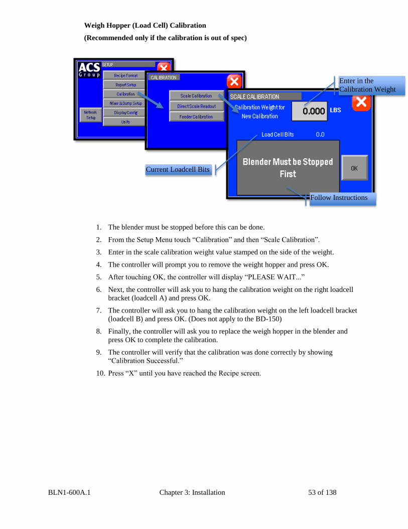
BLN1-600A.1 Chapter 3: Installation 53 of 138
Weigh Hopper (Load Cell) Calibration
(Recommended only if the calibration is out of spec)
1. The blender must be stopped before this can be done.
2. From the Setup Menu touch “Calibration” and then “Scale Calibration”.
3. Enter in the scale calibration weight value stamped on the side of the weight.
4. The controller will prompt you to remove the weight hopper and press OK.
5. After touching OK, the controller will display “PLEASE WAIT...”
6. Next, the controller will ask you to hang the calibration weight on the right loadcell
bracket (loadcell A) and press OK.
7. The controller will ask you to hang the calibration weight on the left loadcell bracket
(loadcell B) and press OK. (Does not apply to the BD-150)
8. Finally, the controller will ask you to replace the weigh hopper in the blender and
press OK to complete the calibration.
9. The controller will verify that the calibration was done correctly by showing
“Calibration Successful.”
10. Press “X” until you have reached the Recipe screen.
Follow Instructions
Enter in the
Calibration Weight
Current Loadcell Bits
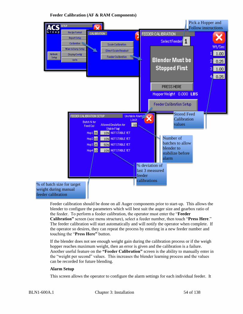
BLN1-600A.1 Chapter 3: Installation 54 of 138
Feeder Calibration (AF & RAM Components)
Feeder calibration should be done on all Auger components prior to start-up. This allows the
blender to configure the parameters which will best suit the auger size and gearbox ratio of
the feeder. To perform a feeder calibration, the operator must enter the “Feeder
Calibration” screen (see menu structure), select a feeder number, then touch “Press Here.”
The feeder calibration will start automatically and will notify the operator when complete. If
the operator so desires, they can repeat the process by entering in a new feeder number and
touching the “Press Here” button.
If the blender does not see enough weight gain during the calibration process or if the weigh
hopper reaches maximum weight, then an error is given and the calibration is a failure.
Another useful feature on the “Feeder Calibration” screen is the ability to manually enter in
the “weight per second” values. This increases the blender learning process and the values
can be recorded for future blending.
Alarm Setup
This screen allows the operator to configure the alarm settings for each individual feeder. It
Follow Instructions
Pick a Hopper and
Follow instructions
Stored Feed
Calibration
values
Number of
batches to allow
blender to
stabilize before
alarm
% deviation of
last 3 measured
feeder
calibrations % of batch size for target
weight during manual
feeder calibration
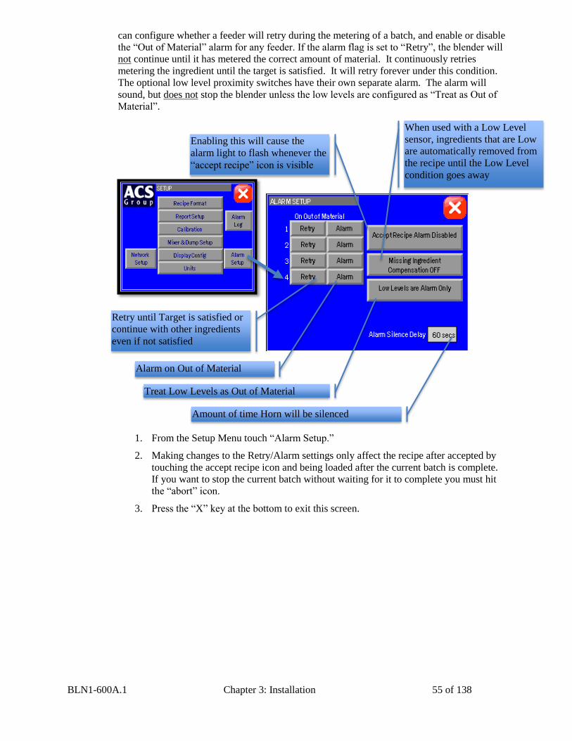
BLN1-600A.1 Chapter 3: Installation 55 of 138
can configure whether a feeder will retry during the metering of a batch, and enable or disable
the “Out of Material” alarm for any feeder. If the alarm flag is set to “Retry”, the blender will
not continue until it has metered the correct amount of material. It continuously retries
metering the ingredient until the target is satisfied. It will retry forever under this condition.
The optional low level proximity switches have their own separate alarm. The alarm will
sound, but does not stop the blender unless the low levels are configured as “Treat as Out of
Material”.
1. From the Setup Menu touch “Alarm Setup.”
2. Making changes to the Retry/Alarm settings only affect the recipe after accepted by
touching the accept recipe icon and being loaded after the current batch is complete.
If you want to stop the current batch without waiting for it to complete you must hit
the “abort” icon.
3. Press the “X” key at the bottom to exit this screen.
Enabling this will cause the
alarm light to flash whenever the
“accept recipe” icon is visible
Retry until Target is satisfied or
continue with other ingredients
even if not satisfied
Alarm on Out of Material
Treat Low Levels as Out of Material
Amount of time Horn will be silenced
When used with a Low Level
sensor, ingredients that are Low
are automatically removed from
the recipe until the Low Level
condition goes away
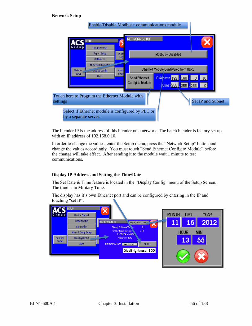
BLN1-600A.1 Chapter 3: Installation 56 of 138
Network Setup
The blender IP is the address of this blender on a network. The batch blender is factory set up
with an IP address of 192.168.0.10.
In order to change the values, enter the Setup menu, press the “Network Setup” button and
change the values accordingly. You must touch “Send Ethernet Config to Module” before
the change will take effect. After sending it to the module wait 1 minute to test
communications.
Display IP Address and Setting the Time/Date
The Set Date & Time feature is located in the “Display Config” menu of the Setup Screen.
The time is in Military Time.
The display has it’s own Ethernet port and can be configured by entering in the IP and
touching “set IP”.
Enable/Disable Modbus+ communications module
Select if Ethernet module is configured by PLC or
by a separate server.
Set IP and Subnet
Touch here to Program the Ethernet Module with
settings
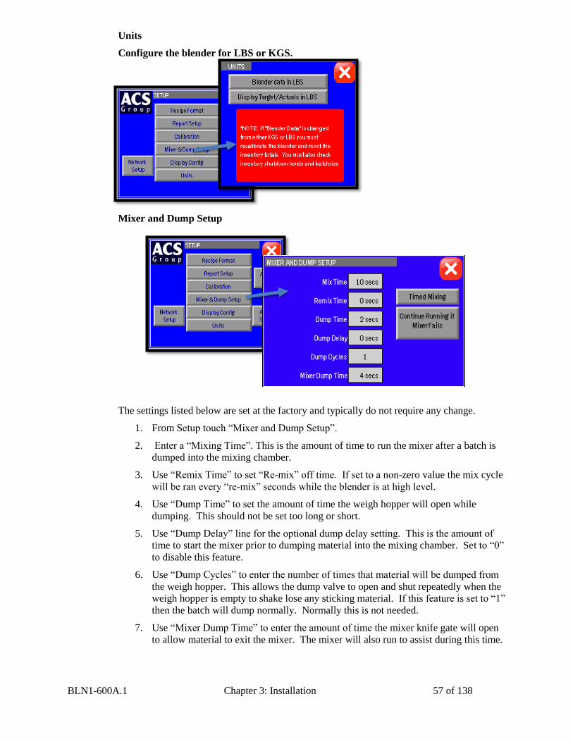
BLN1-600A.1 Chapter 3: Installation 57 of 138
Units
Configure the blender for LBS or KGS.
Mixer and Dump Setup
The settings listed below are set at the factory and typically do not require any change.
1. From Setup touch “Mixer and Dump Setup”.
2. Enter a “Mixing Time”. This is the amount of time to run the mixer after a batch is
dumped into the mixing chamber.
3. Use “Remix Time” to set “Re-mix” off time. If set to a non-zero value the mix cycle
will be ran every “re-mix” seconds while the blender is at high level.
4. Use “Dump Time” to set the amount of time the weigh hopper will open while
dumping. This should not be set too long or short.
5. Use “Dump Delay” line for the optional dump delay setting. This is the amount of
time to start the mixer prior to dumping material into the mixing chamber. Set to “0”
to disable this feature.
6. Use “Dump Cycles” to enter the number of times that material will be dumped from
the weigh hopper. This allows the dump valve to open and shut repeatedly when the
weigh hopper is empty to shake lose any sticking material. If this feature is set to “1”
then the batch will dump normally. Normally this is not needed.
7. Use “Mixer Dump Time” to enter the amount of time the mixer knife gate will open
to allow material to exit the mixer. The mixer will also run to assist during this time.
BLN1-600A.1 Chapter 3: Installation 58 of 138
8. Press “X” to return to the “Setup” screen.
3-6 Initial Startup
The operator can start the blender by touching on the Recipe Page.
The switch will show when running. If the operator selects “Stop Blender” then the
current batch in progress is first finished and then the blender will stop making new batches.
To immediately stop the blender, the operator can touch on the Recipe Page. This will
cause the blender to stop making the current batch immediately. If the blender is stopped in
this method then the current batch will not be completed properly.
BLN1-600A.1 Chapter 4: Operation 59 of 138
Chapter 4: Operation
4-1 Start-up
General Operation
The general operation of the Batch blending system is as follows: Once the system is properly
installed and set up, the system will be ready for operation. Please see the Installation and
Setup chapter in this manual for further information.
Once the batch blending system is powered on, the unit will display the recipe screen (the
recipe format should be in “EZ Recipe” mode). Pressing the highlighted box on the feeder
number, the operator can enter a valid recipe or use a previously stored recipe from the recipe
book.
1. The blender is started by turning system on or material dropping below level switch
in mix chamber.
2. Metering gates are opened (or auger motors are turned on) to meter material into the
weigh hopper in the programmed order.
3. Each component is weighed, then the batch is dumped into the mix chamber
(provided the mixer “High level” switch is not covered).
4. The material is mixed in the mix chamber and flows into the processing machine.
5. The optional slide gate below the mixer may control the flow of material to the
molding machine or extruder.
BLN1-600A.1 Chapter 4: Operation 60 of 138
Quick Start Procedure
New Recipes
1. Verify the weigh hopper calibration before running the blender (page 47)
2. Ensure that all ingredient supply hoppers to be used are filled with material. Virgin
material should be loaded into hopper #1 and regrind into hopper #3.
3. Enter the recipe menu on the touch screen by turning on the touch screen controller
(It will automatically default to this screen), and enter the blend recipe desired
following the steps listed below:
a. Touch the hopper and enter a new value (0 to 999.99), then hit the green arrow.
b. After you have entering all values push the “Accept New Recipe” icon
Existing Recipes
The operator can load a previously stored recipe from the Recipe Book. The Recipe book
also allows the operators to save the current running recipe. This can be done by performing
the following steps:
1. Touch the Recipe Book icon located on the Recipe Screen.
2. Select a stored recipe by changing the number next to “Recipe #”
3. Touch the “load recipe” icon
4. Touch the “accept new recipe” icon
To edit/save a recipe to the Recipe Book:
1. Go to the Recipe Book by touching the Recipe Book icon.
2. Select a stored recipe by changing the number next to “Recipe #”.
3. Make desired changes to the stored recipe.
4. Touch the “save” icon and wait for it to disappear.
Hopper #3 on some models is equipped with an oversized square gate to
assist in the feeding of the regrind material.
The blender only shows the “accept new recipe” icon if the recipe is valid.
Recipes can also be changed while the blender is running. The new accepted
recipe is loaded at the beginning of the next batch. This allows the operator
to modify the new recipe without affecting the blender until they hit the
“Accept New Recipe” button.
BLN1-600A.1 Chapter 4: Operation 61 of 138
4-2 Operation Procedures The objective of this section is to familiarize the reader with the Slide Gate blender recipe
menus, run mode operation, run mode menus and displays. Upon the completion of this
section, the reader will be familiar with the recipes and run mode displays that are available
on one blender, including the recipe book and recipe storage facilities. Other items covered in
this section are optional printer functions and report generation capabilities of the Batch
blending system.
Topics covered in this section are:
General Operation
Recipe Menu
Recipe Book
Cleanout Mode
Inventory Page
Inventory Shutdown Event
Recipe Formats
Optional Printer Menu
All personnel operating the Batch blending system should read this section of the manual
before operating the blending system.
Operator Displays
The batch blending system utilizes a standardized menu format. Each screen was designed
to be user-friendly and provide the operator with the necessary information to run the blender.
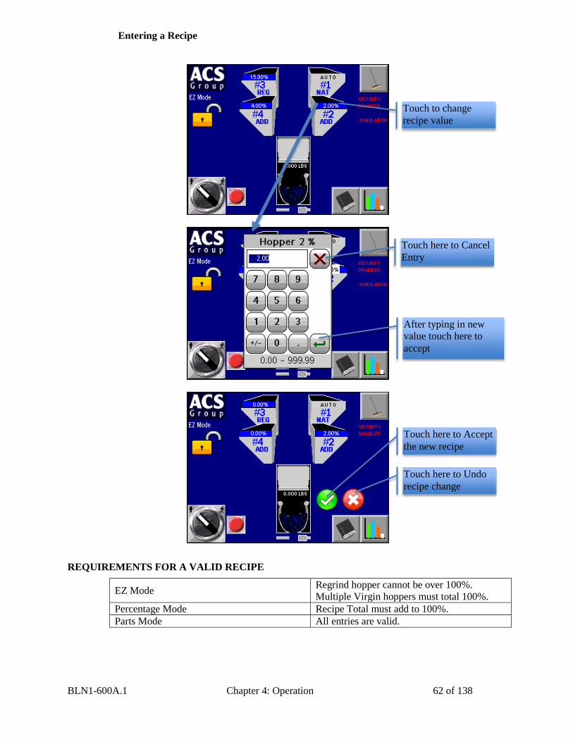
BLN1-600A.1 Chapter 4: Operation 62 of 138
Entering a Recipe
REQUIREMENTS FOR A VALID RECIPE
EZ Mode Regrind hopper cannot be over 100%.
Multiple Virgin hoppers must total 100%.
Percentage Mode Recipe Total must add to 100%.
Parts Mode All entries are valid.
Touch to change
recipe value
After typing in new
value touch here to
accept
Touch here to Cancel
Entry
Touch here to Accept
the new recipe
Touch here to Undo
recipe change
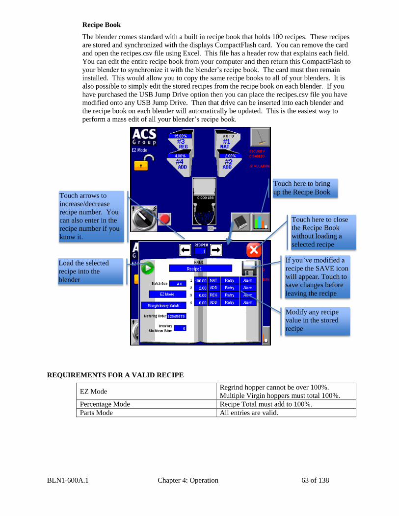
BLN1-600A.1 Chapter 4: Operation 63 of 138
Recipe Book
The blender comes standard with a built in recipe book that holds 100 recipes. These recipes
are stored and synchronized with the displays CompactFlash card. You can remove the card
and open the recipes.csv file using Excel. This file has a header row that explains each field.
You can edit the entire recipe book from your computer and then return this CompactFlash to
your blender to synchronize it with the blender’s recipe book. The card must then remain
installed. This would allow you to copy the same recipe books to all of your blenders. It is
also possible to simply edit the stored recipes from the recipe book on each blender. If you
have purchased the USB Jump Drive option then you can place the recipes.csv file you have
modified onto any USB Jump Drive. Then that drive can be inserted into each blender and
the recipe book on each blender will automatically be updated. This is the easiest way to
perform a mass edit of all your blender’s recipe book.
REQUIREMENTS FOR A VALID RECIPE
EZ Mode Regrind hopper cannot be over 100%.
Multiple Virgin hoppers must total 100%.
Percentage Mode Recipe Total must add to 100%.
Parts Mode All entries are valid.
Touch here to bring
up the Recipe Book
Modify any recipe
value in the stored
recipe
Touch here to close
the Recipe Book
without loading a
selected recipe
Load the selected
recipe into the
blender
Touch arrows to
increase/decrease
recipe number. You
can also enter in the
recipe number if you
know it.
If you’ve modified a
recipe the SAVE icon
will appear. Touch to
save changes before
leaving the recipe
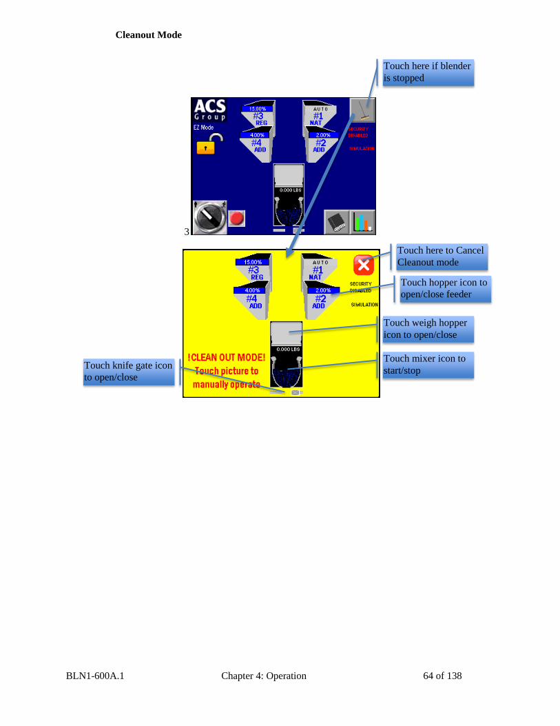
BLN1-600A.1 Chapter 4: Operation 64 of 138
Cleanout Mode
3
Touch here if blender
is stopped
Touch hopper icon to
open/close feeder
Touch weigh hopper
icon to open/close
Touch mixer icon to
start/stop Touch knife gate icon
to open/close
Touch here to Cancel
Cleanout mode
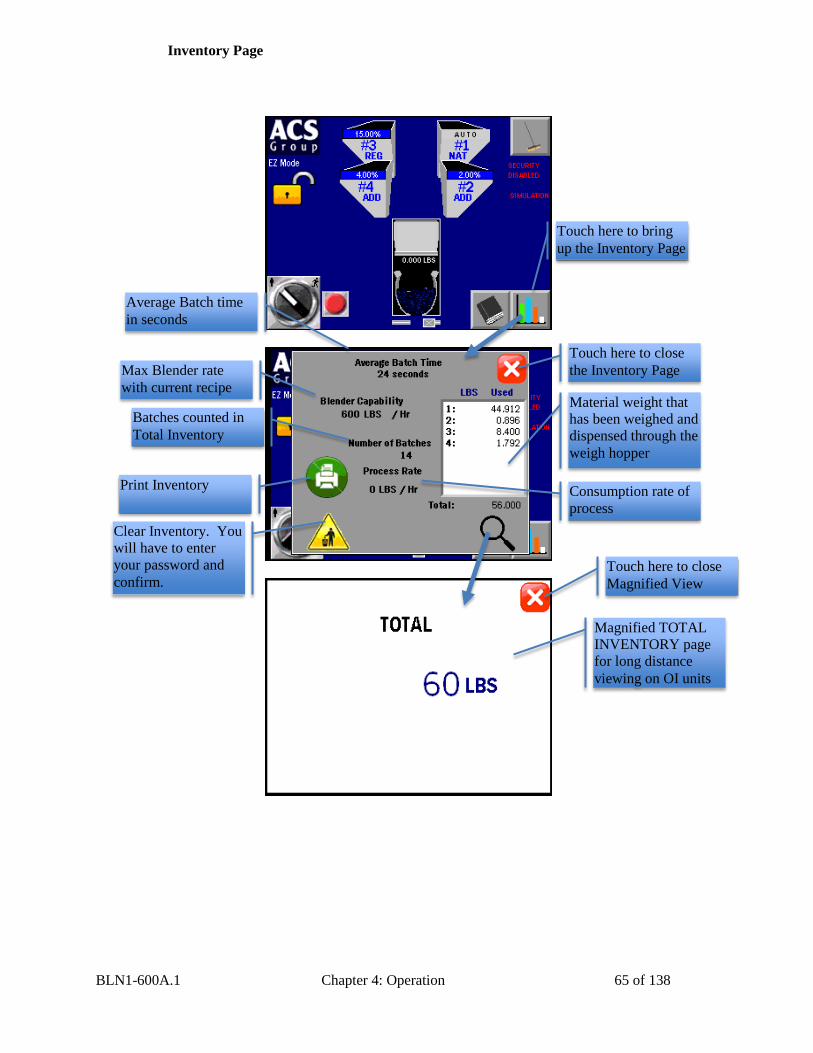
BLN1-600A.1 Chapter 4: Operation 65 of 138
Inventory Page
Touch here to bring
up the Inventory Page
Material weight that
has been weighed and
dispensed through the
weigh hopper
Print Inventory
Magnified TOTAL
INVENTORY page
for long distance
viewing on OI units
Clear Inventory. You
will have to enter
your password and
confirm.
Touch here to close
the Inventory Page
Batches counted in
Total Inventory
Max Blender rate
with current recipe
Average Batch time
in seconds
Consumption rate of
process
Touch here to close
Magnified View
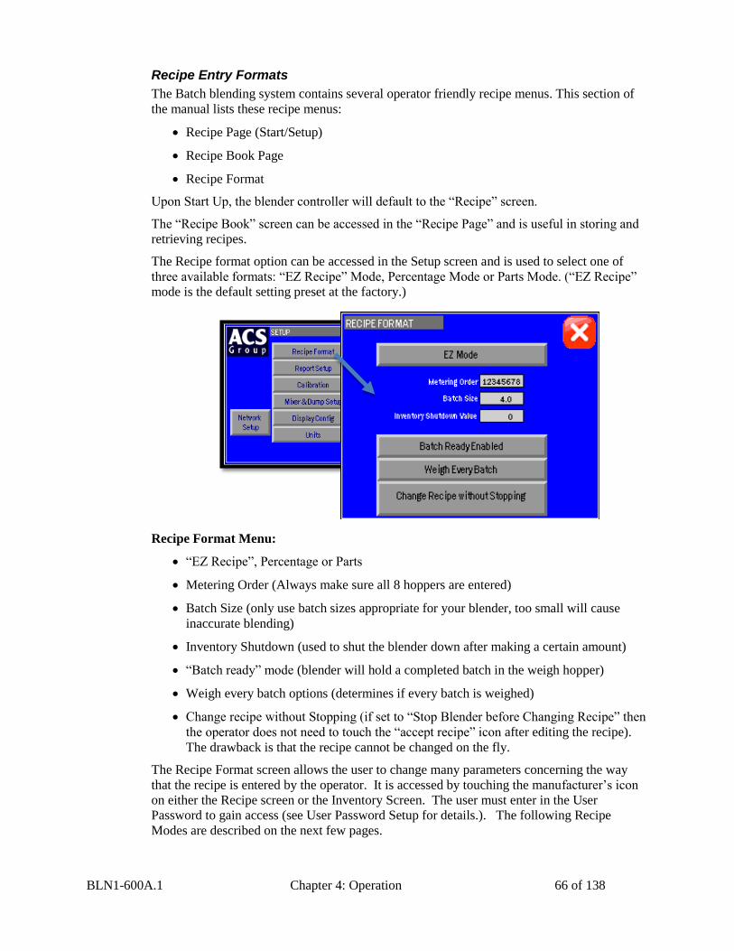
BLN1-600A.1 Chapter 4: Operation 66 of 138
Recipe Entry Formats
The Batch blending system contains several operator friendly recipe menus. This section of
the manual lists these recipe menus:
Recipe Page (Start/Setup)
Recipe Book Page
Recipe Format
Upon Start Up, the blender controller will default to the “Recipe” screen.
The “Recipe Book” screen can be accessed in the “Recipe Page” and is useful in storing and
retrieving recipes.
The Recipe format option can be accessed in the Setup screen and is used to select one of
three available formats: “EZ Recipe” Mode, Percentage Mode or Parts Mode. (“EZ Recipe”
mode is the default setting preset at the factory.)
Recipe Format Menu:
“EZ Recipe”, Percentage or Parts
Metering Order (Always make sure all 8 hoppers are entered)
Batch Size (only use batch sizes appropriate for your blender, too small will cause
inaccurate blending)
Inventory Shutdown (used to shut the blender down after making a certain amount)
“Batch ready” mode (blender will hold a completed batch in the weigh hopper)
Weigh every batch options (determines if every batch is weighed)
Change recipe without Stopping (if set to “Stop Blender before Changing Recipe” then
the operator does not need to touch the “accept recipe” icon after editing the recipe).
The drawback is that the recipe cannot be changed on the fly.
The Recipe Format screen allows the user to change many parameters concerning the way
that the recipe is entered by the operator. It is accessed by touching the manufacturer’s icon
on either the Recipe screen or the Inventory Screen. The user must enter in the User
Password to gain access (see User Password Setup for details.). The following Recipe
Modes are described on the next few pages.
BLN1-600A.1 Chapter 4: Operation 67 of 138
“EZ Recipe” Mode (Most common in injection molding)
The “EZ Recipe” menu structure allows recipes to be entered and adjusted by touching the
buttons on the panel face (for 1 to 6 components). In this mode, hopper #1 is configured as
virgin, hopper #3 is configured as regrind, and the others are configured as additives, i.e.
color. The operator enters in the percentage of regrind and additives, and the virgin
percentage is automatically calculated. The regrind percentage represents a percentage of the
total batch, and the additives are based on a percentage of the virgin weight. This is useful
because the percentage of regrind can be changed without affecting the ratio of color or
additive to the virgin weight. Each percentage can be up to 100%, but not greater. The virgin
percentage is automatically calculated by the blender and the operator is not required to enter
it.
The ingredient names selected will be displayed on the run mode display so the operator will
know what material is being blended.
The #1 hopper (“NAT” - Virgin Material) recipe ingredient will not be
shown on the recipe setup menu.
ADD (Additive) designations will weigh the ingredient as a percentage of
natural material only.
RGD (Regrind) designations will weigh the ingredient as a percentage of the
total batch. (It is assumed the regrind has been generated from pre-blended
production and already contains the same color and/or additives.)
Virgin material must be loaded into hopper #1 and regrind into hopper #3.
Component #3 is designed to handle regrind and most models come
equipped with a larger, square gate to reduce the likelihood of bridging. If
regrind is being used, it should always be run through component #3. If you
don’t have regrind, another major ingredient can be run through
component #3.
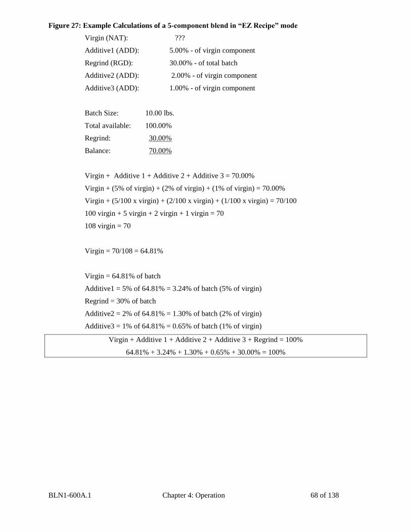
BLN1-600A.1 Chapter 4: Operation 68 of 138
Figure 27: Example Calculations of a 5-component blend in “EZ Recipe” mode
Virgin (NAT): ???
Additive1 (ADD): 5.00% - of virgin component
Regrind (RGD): 30.00% - of total batch
Additive2 (ADD): 2.00% - of virgin component
Additive3 (ADD): 1.00% - of virgin component
Batch Size: 10.00 lbs.
Total available: 100.00%
Regrind: 30.00%
Balance: 70.00%
Virgin + Additive 1 + Additive 2 + Additive 3 = 70.00%
Virgin + (5% of virgin) + (2% of virgin) + (1% of virgin) = 70.00%
Virgin + (5/100 x virgin) + (2/100 x virgin) + (1/100 x virgin) = 70/100
100 virgin + 5 virgin + 2 virgin + 1 virgin = 70
108 virgin = 70
Virgin = 70/108 = 64.81%
Virgin = 64.81% of batch
Additive1 = 5% of 64.81% = 3.24% of batch (5% of virgin)
Regrind = 30% of batch
Additive2 = 2% of 64.81% = 1.30% of batch (2% of virgin)
Additive3 = 1% of 64.81% = 0.65% of batch (1% of virgin)
Virgin + Additive 1 + Additive 2 + Additive 3 + Regrind = 100%
64.81% + 3.24% + 1.30% + 0.65% + 30.00% = 100%
BLN1-600A.1 Chapter 4: Operation 69 of 138
“Percentage” Mode (Most common in extrusion and blow molding)
Extrusion processing often requires recipes in percentage format, especially if regrind is not
involved, i.e. blown or cast film.
In this mode, operators enter in values for each hopper up to 100%. The total of all the
hoppers must equal 100%. If they don’t, an error message appears on the Recipe screen and
prevents the recipe from being accepted. All hoppers are a percentage of the total batch size.
“Parts” Mode (Often used in Compounding Applications)
The “Parts” recipe entry mode lets the operator enter in values based on a parts ratio rather
than a percentage. Each entry can be up to 999.99 and the total of all hoppers does not have
to be 100. After all values are entered, the total parts are calculated. The individual hopper
target is then calculated based on each hopper’s entered parts. These parts represent ratios of
the total batch. For instance: Hop 1=300 parts, Hop 2=100 parts, Hop 3=10 parts, Hop 4=5
parts. This would mean that if the batch was divided into 415 parts, then Hop 1 would make
up 300 of those parts, Hop 2 would make up 100, Hop 3 10 parts, and Hop 4 5 parts.
Figure 28: Example Calculations of a 4-component blend in “Parts” mode
Feeder Tag Preset Part Calculated Weight
(Ratio Control)
Virgin #1 7,200 7,200/10,000
Regrind #2 2,000 2,000/10,000
Color #3 500 500/10,000
Additive #4 300 300/10,000
Total: 10,000
Switching Modes
Recipe Modes can be switched while the blender is making a batch. At any time the operator
can switch the recipe entry mode without affecting the current batch being made. The recipe
mode is part of the “New Recipe” and is separate from the running recipe.
Recipe Setup
Metering Order
The Batch blender allows the operator to set the ingredient metering order when making a
batch. In order to access the metering order menu, enter the Setup menu and press the
“Recipe Format” button (refer to the menu structure on page 39). Once in the “Recipe
Format” menu, view “Metering Order.” This display will indicate the current order in which
the ingredients are metered. A Metering Order of “12345678” means that the blender will
feed hopper 1 first and hopper 8 last.
In order to change the metering order, simply press the “Metering Order” button. In the next
screen, the operator must select a value from 1 to 87654321 and press the green enter key.
Once the desired metering order is displayed, simply press the “X” exit. If the order is
changed, then you will need to touch “Accept New Recipe” icon on the Recipe Screen
before the change takes effect.
All ingredients are weighed as a percentage of the total batch.
The preset part will be divided by the total of all parts, with each part
representing the calculated weight for ratio control.
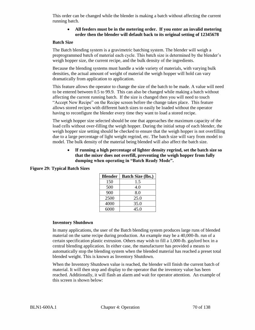
BLN1-600A.1 Chapter 4: Operation 70 of 138
This order can be changed while the blender is making a batch without affecting the current
running batch.
Batch Size
The Batch blending system is a gravimetric batching system. The blender will weigh a
preprogrammed batch of material each cycle. This batch size is determined by the blender’s
weigh hopper size, the current recipe, and the bulk density of the ingredients.
Because the blending systems must handle a wide variety of materials, with varying bulk
densities, the actual amount of weight of material the weigh hopper will hold can vary
dramatically from application to application.
This feature allows the operator to change the size of the batch to be made. A value will need
to be entered between 0.5 to 99.9. This can also be changed while making a batch without
affecting the current running batch. If the size is changed then you will need to touch
“Accept New Recipe” on the Recipe screen before the change takes place. This feature
allows stored recipes with different batch sizes to easily be loaded without the operator
having to reconfigure the blender every time they want to load a stored recipe.
The weigh hopper size selected should be one that approaches the maximum capacity of the
load cells without over-filling the weigh hopper. During the initial setup of each blender, the
weigh hopper size setting should be checked to ensure that the weigh hopper is not overfilling
due to a large percentage of light weight regrind, etc. The batch size will vary from model to
model. The bulk density of the material being blended will also affect the batch size.
Figure 29: Typical Batch Sizes
Blender Batch Size (lbs.)
150 1.5
500 4.0
900 8.0
2500 25.0
4000 35.0
6000 45.0
Inventory Shutdown
In many applications, the user of the Batch blending system produces large runs of blended
material on the same recipe during production. An example may be a 40,000-lb. run of a
certain specification plastic extrusion. Others may wish to fill a 1,000-lb. gaylord box in a
central blending application. In either case, the manufacturer has provided a means to
automatically stop the blending system when the blended material has reached a preset total
blended weight. This is known as Inventory Shutdown.
When the Inventory Shutdown value is reached, the blender will finish the current batch of
material. It will then stop and display to the operator that the inventory value has been
reached. Additionally, it will flash an alarm and wait for operator attention. An example of
this screen is shown below:
All feeders must be in the metering order. If you enter an invalid metering
order then the blender will default back to its original setting of 12345678
If running a high percentage of lighter density regrind, set the batch size so
that the mixer does not overfill, preventing the weigh hopper from fully
dumping when operating in “Batch Ready Mode”.
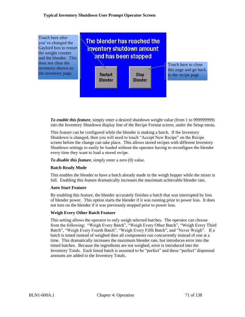
BLN1-600A.1 Chapter 4: Operation 71 of 138
Typical Inventory Shutdown User Prompt Operator Screen
To enable this feature, simply enter a desired shutdown weight value (from 1 to 999999999)
into the Inventory Shutdown display line of the Recipe Format screen, under the Setup menu.
This feature can be configured while the blender is making a batch. If the Inventory
Shutdown is changed, then you will need to touch “Accept New Recipe” on the Recipe
screen before the change can take place. This allows stored recipes with different Inventory
Shutdown settings to easily be loaded without the operator having to reconfigure the blender
every time they want to load a stored recipe.
To disable this feature, simply enter a zero (0) value.
Batch Ready Mode
This enables the blender to have a batch already made in the weigh hopper while the mixer is
full. Enabling this feature dramatically increases the maximum achievable blender rate.
Auto Start Feature
By enabling this feature, the blender accurately finishes a batch that was interrupted by loss
of blender power. This option starts the blender if it was running prior to power loss. It does
not turn on the blender if it was previously stopped prior to power loss.
Weigh Every Other Batch Feature
This setting allows the operator to only weigh selected batches. The operator can choose
from the following: “Weigh Every Batch”, “Weigh Every Other Batch”, “Weigh Every Third
Batch”, “Weigh Every Fourth Batch”, “Weigh Every Fifth Batch”, and “Never Weigh”. If a
batch is timed instead of weighed then all components run concurrently instead of one at a
time. This dramatically increases the maximum blender rate, but introduces error into the
timed batches. Because the ingredients are not weighed, error is introduced into the
Inventory Totals. Each timed batch is assumed to be “perfect” and these “perfect” dispensed
amounts are added to the Inventory Totals.
Touch here to close
this page and go back
to the recipe page
Touch here after
you’ve changed the
Gaylord box to restart
the weight counter
and the blender. This
does not clear the
inventory shown on
the inventory page.
BLN1-600A.1 Chapter 4: Operation 72 of 138
Every Batch:
This mode of operation weighs every component of every batch that is metered by the
Batch blending system.
Every Other Batch:
First batch weighed. Second batch is metered based on the metering times of the first
batch.
Every Third Batch:
First batch weighed. Second and third batches are metered based on the metering times
of the first batch.
Every Fourth Batch:
First batch weighed. Second, third, and fourth batches are metered based on the metering
times of the first batch.
Every Fifth Batch:
First batch weighed. Second, third, fourth, and fifth batches are metered based on the
metering times of the first batch.
Never Weigh:
Metering is based on Feed Calibration values only. Loadcells are not used. This is only
used if you have a failed loadcell.
Not weighing every batch sacrifices blender weighing accuracy, but
increases the blender’s maximum rate.
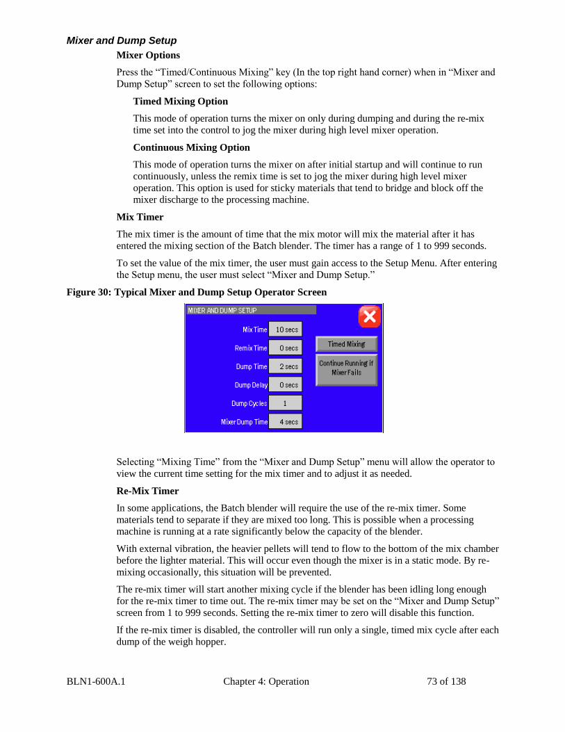
BLN1-600A.1 Chapter 4: Operation 73 of 138
Mixer and Dump Setup
Mixer Options
Press the “Timed/Continuous Mixing” key (In the top right hand corner) when in “Mixer and
Dump Setup” screen to set the following options:
Timed Mixing Option
This mode of operation turns the mixer on only during dumping and during the re-mix
time set into the control to jog the mixer during high level mixer operation.
Continuous Mixing Option
This mode of operation turns the mixer on after initial startup and will continue to run
continuously, unless the remix time is set to jog the mixer during high level mixer
operation. This option is used for sticky materials that tend to bridge and block off the
mixer discharge to the processing machine.
Mix Timer
The mix timer is the amount of time that the mix motor will mix the material after it has
entered the mixing section of the Batch blender. The timer has a range of 1 to 999 seconds.
To set the value of the mix timer, the user must gain access to the Setup Menu. After entering
the Setup menu, the user must select “Mixer and Dump Setup.”
Figure 30: Typical Mixer and Dump Setup Operator Screen
Selecting “Mixing Time” from the “Mixer and Dump Setup” menu will allow the operator to
view the current time setting for the mix timer and to adjust it as needed.
Re-Mix Timer
In some applications, the Batch blender will require the use of the re-mix timer. Some
materials tend to separate if they are mixed too long. This is possible when a processing
machine is running at a rate significantly below the capacity of the blender.
With external vibration, the heavier pellets will tend to flow to the bottom of the mix chamber
before the lighter material. This will occur even though the mixer is in a static mode. By re-
mixing occasionally, this situation will be prevented.
The re-mix timer will start another mixing cycle if the blender has been idling long enough
for the re-mix timer to time out. The re-mix timer may be set on the “Mixer and Dump Setup”
screen from 1 to 999 seconds. Setting the re-mix timer to zero will disable this function.
If the re-mix timer is disabled, the controller will run only a single, timed mix cycle after each
dump of the weigh hopper.
BLN1-600A.1 Chapter 4: Operation 74 of 138
To view and change the value of the re-mix timer, refer to the “Mixer and Dump Setup”
menu. All current values for Mixing and Remixing Times will be shown on this screen. The
re-mix timer default value is factory preset at zero.
Weigh Hopper Dump Time
The weigh hopper dump time is the amount of time the weigh hopper’s dump valve remains
open to allow weighed material to exit the hopper and enter the mixer.
To view and change the current weigh hopper dump time settings, enter the Setup menu and
select the “Mixer and Dump Setup” screen. Press the field next to “Dump Time” to set the
operation of the Dump Valve.
The timer should be set to close the dump valve shortly after the material has totally dumped
from the weigh hopper. This time can vary due to material flow characteristics, and the size
of the batch that is programmed into the blender control. Experimentation with this setting
can allow the operator to determine the best cycle for the material being weighed.
Weigh Hopper Dump Delay Time
The dump delay time is the amount of time from the end of metering the last ingredient until
the start of the actual dump cycle. The start of the dump cycle is marked by the opening of
the weigh hopper dump valve. This value has a range from 1 second to 999 seconds. To view
and change the current dump delay time, enter the Setup Menu, select “Mixer and Dump
Setup” screen, and then select “Dump Delay”.
The default time is factory set at zero seconds. This delay time is used to start the mixer prior
to dumping the material from the weigh hopper into the mix chamber of the blender.
Weigh Hopper Dump Cycle
The dump cycle allows the weigh hopper dump valve to cycle, or open and close, a number
of times prior to commencing with the next batch cycle. The setting allows from 1 to 9 dump
cycles between batches (open and closed cycles).
The normal and default factory setting is 1, meaning the weigh hopper dump valve will open
at the end of the weighed batch and close after the batch is discharged into the mixer.
Setting the dump cycle to more than one cycle may be useful when blending high static, dusty
material or those that have sticky tendencies. This will cycle the dump valve open and closed
to allow any material that may cling to the dump valve.
To enter the dump cycle menu, first enter the Setup menu by pressing the Manufacturer’s
icon from the main menu. Enter the password and press enter. Next, press the button marked
“Mixer and Dump Setup”. The display will show the “Mixer and Dump Setup” menu. Press
the “Dump Cycle” key to enter a dump cycle value and press enter. Please refer to the menu
structure tree shown in section 3-5.
Mixer Dump Time
The mixer dump time is the amount of time the knife gate below mixer’s valve remains open
to allow blended material to exit the blender.
To view and change the current mixer dump time settings, enter the Setup menu and select
the “Mixer and Dump Setup” screen. Press the field next to “Mixer Dump Time” to set the
operation of the Dump Valve.
The timer should be set to close the dump valve shortly after all material has been emptied
from the mix chamber. This time can vary due to material flow characteristics, and the size
of the batch that is programmed into the blender control. Experimentation with this setting
can allow the operator to determine the best cycle for the material being mixed.
BLN1-600A.1 Chapter 4: Operation 75 of 138
Continue/Stop Running if Mixer Fails
If the blender is configured with the “Mixer Failure Detection” option then the user can select
if he wants the blender to alarm only or stop if the mixer movement is not detected during
mixing.
Alarm Messages
An alarm message will be shown if any alarm condition occurs. A message will pop up on
the screen until the alarm condition is resolved. During an alarm condition, not only will a
visual alarm show up on the screen but also an audible alarm will sound. The operator can
press “OK” on this pop-up to hide the screen temporarily, but if the alarm condition is still
unresolved, then the message and horn will reappear after a short delay.
The blender will log when the alarm event occurred and when the condition went away.
The following is a list of all alarm names and descriptions:
Hopper 1-8 Out of Material: This alarm indicates that a hopper is out of material and
signals the operator that they should check the resin system.
Hopper 1-8 Low Level: This alarm indicates that a hopper with a low level prox sensor is
low.
Surge Hopper Empty: This alarm indicates that the surge hopper sensor is sensing a low
level. This can be any surge hopper and not necessarily related to the blender. It is a
customer specified alarm input.
Mixer Failure: This alarm indicates that mixer movement was not detected when it was
suppose to be. This is only available if the Optional “Mixer Failure” feature has been added
to the blender.
Unable to Make Rate: This alarm indicates that the blender has not hit high level in an
appropriate amount of time.
Hopper 1-8 Unstable Alarm: This alarm indicates that a hopper has not stabilized. This is
determined by examining the last 3 feed calibration measurements while the blender is
running. If the 3 measurements are within a set deviation of each other than the hopper is
“stable” and these measurements are used to average the feed calibration value. If not then a
counter is increased every batch and the feed calibration value remains unchanged. After a
set amount of batches that are not “stable” then an alarm is given.
Hopper 1-8 Overfeed Alarm: This alarm indicates that a hopper has put too much into the
current batch.
Max Hopper Weight Exceeded, check batch size: This alarm indicates that the weight in
the weigh hopper has exceeded the maximum allowed weight. This alarm can happen if the
operator changes material density and does not perform a feeder calibration, but will usually
be automatically fixed after the first batch. As long as this alarm doesn’t continue to
reappear, then the operator should not be concerned. If the alarm continues to occur, then the
operator should have maintenance check the blender.
Calibration Error, Clean out hopper and check calibration: This alarm indicates that the
maximum empty weight for the weigh hopper has been exceeded. The blender will
automatically tare up to 0.25 lbs of material, but if this weight is exceeded, then an alarm will
appear. This alarm is most commonly caused by a build up of sticky material in the weigh
hopper and can be corrected by simply cleaning out the weigh hopper. If this does not correct
the problem, then the scale calibration should be checked by maintenance.
BLN1-600A.1 Chapter 4: Operation 76 of 138
Power Interruption while metering a Batch: This alarm indicates that the blender’s power
was turned off while the blender was making a batch. The batch accuracy would have been
compromised since it did not finish the batch in progress.
PLC Battery Low: PLC battery is low and may cause the blender to lose both the program
and the blender configuration. Notify Maintenance immediately.
PLC Module Loaded: This alarm occurs after a software upgrade to the PLC. The alarm
instructs you to turn off power to the blender, remove the Memory Module, turn on power,
and then reconfigure the blender parameters.
Inventory Cleared: This is only logged in the Alarm Log and does not cause a pop-up
message or audible alarm. Each time the inventory is cleared, the time and date are logged to
the Alarm Log. An alarm will sound and a screen will pop up when Auto. Inventory
Shutdown has been reached.
E-Stop Screen: The blender is equipped with an System-stop switch that removes the power
from all mechanical outputs. The System-stop Screen appears along with an audible alarm
whenever the System-stop is activated. The operator can not access any screens until
System-stop is deactivated. The Panel View will then put the screen back to the display that
the operator was on prior to hitting the System-stop. The System-stop does not provide a
category 0 or 1 stop. It is recommended that the System-stop be moved closer to the power
input so as to disconnect all power when the System-stop is pushed.
Blending Mode Sequence
Once the operator initiates the run mode of operation, the blending system controller will
begin monitoring the mixer high-level switch. Nothing will happen until the mixer high-level
switch is uncovered. This tells the controller that the mixing chamber is capable of holding
another batch of material.
Once the mixer high-level switch is uncovered, and the weigh hopper has dumped, the system
will meter the ingredients from the supply hoppers, through the metering units, into the weigh
hopper. Each component will be metered individually to allow accurate weighing of the
material.
Each component is metered in the order specified by the “Metering Order” setup. See the
Installation & Setup chapter for further details.
Once the final ingredient specified in the recipe has been metered into the weigh hopper, the
controller will take a final weight reading of the weigh hopper. This will start the “Dump
Delay” timer. (See Page 58). Once the dump delay timer has timed out, the controller will
activate the weigh hopper dump valve, initiating the weigh hopper dump cycle.
The open weigh hopper dump door will allow the material to drop into the mixer section of
the blender. If the dump delay is set, the mixer will start before the weigh hopper dump will
open for the selected time.
The blender will sit at rest until the high-level sensor in the mixing chamber is uncovered to
start another weigh cycle. (Unless the Re-Mix timer is set to a value other than 0 and times
out to restart the mixer to run for another mix cycle.)
The level sensor is located on the back wall of the mixer chamber. If the sensor is covered
with material, the indicator light on the back of the sensor will be lit.
Before starting Batch blending systems, each ingredient hopper in the
current recipe must contain material! Virgin material must be loaded in
hopper #1 and hopper #3 should only be used for regrind!!
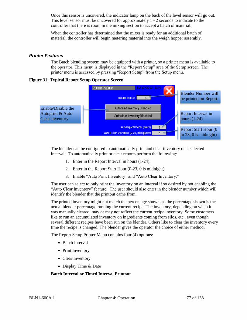
BLN1-600A.1 Chapter 4: Operation 77 of 138
Once this sensor is uncovered, the indicator lamp on the back of the level sensor will go out.
This level sensor must be uncovered for approximately 1 - 2 seconds to indicate to the
controller that there is room in the mixing section to accept a batch of material.
When the controller has determined that the mixer is ready for an additional batch of
material, the controller will begin metering material into the weigh hopper assembly.
Printer Features
The Batch blending system may be equipped with a printer, so a printer menu is available to
the operator. This menu is displayed in the “Report Setup” area of the Setup screen. The
printer menu is accessed by pressing “Report Setup” from the Setup menu.
Figure 31: Typical Report Setup Operator Screen
The blender can be configured to automatically print and clear inventory on a selected
interval. To automatically print or clear reports perform the following:
1. Enter in the Report Interval in hours (1-24).
2. Enter in the Report Start Hour (0-23, 0 is midnight).
3. Enable “Auto Print Inventory” and “Auto Clear Inventory.”
The user can select to only print the inventory on an interval if so desired by not enabling the
“Auto Clear Inventory” feature. The user should also enter in the blender number which will
identify the blender that the printout came from.
The printed inventory might not match the percentage shown, as the percentage shown is the
actual blender percentage running the current recipe. The inventory, depending on when it
was manually cleared, may or may not reflect the current recipe inventory. Some customers
like to run an accumulated inventory on ingredients coming from silos, etc., even though
several different recipes have been run on the blender. Others like to clear the inventory every
time the recipe is changed. The blender gives the operator the choice of either method.
The Report Setup Printer Menu contains four (4) options:
Batch Interval
Print Inventory
Clear Inventory
Display Time & Date
Batch Interval or Timed Interval Printout
Blender Number will
be printed on Report
Report Interval in
hours (1-24)
Report Start Hour (0
to 23, 0 is midnight)
Enable/Disable the
Autoprint & Auto
Clear Inventory
BLN1-600A.1 Chapter 4: Operation 78 of 138
The Batch Interval item under the Recipe menu works in conjunction with the Auto Print
Interval to set the number of batches between printouts or on a timed interval between
printouts.
Timed Printout
When entering the Report Setup menu, the operator will have to decide whether the printout
should be timed and by the number of batches between each printout. The operator will have
to toggle between the “Recipe Format” and the “Report Setup” screens to configure the
settings properly.
If you want to print out on a time format, press the button next to the “Auto Print/Clear
Interval” key. The screen will then prompt the operator to set the time interval in hours (1 to
24).
If you want to change the hours between printouts, press the “Auto Print/Clear Interval” key
again to change the value to the desired time.
The operator will then need to program in when they want to begin the timed printouts.
Simply select the time (0-23, {midnight =0} on a 24-hour clock) and press the “Done” key to
retain the current settings in the “Report Setup” screen.
Batch Printout
The target vs actual weight data for every batch can also be printed. See “Advanced Weight
Options” to turn this on/off. This feature uses an excessive amount of paper and should only
be used for trouble shooting.
Print Inventory
The print inventory menu item is used to produce on demand, inventory printouts. Before
selecting this item, be sure that the printer is properly connected and ready. This function will
generate an inventory printout with the current date and time information.
Display Time and Date
The display Time and Date item in the upper right corner of the “Report Setup” menu is used
to verify the current time and date information.
Color Changes
The color change procedure is meant for use with the basic Batch Blender. This procedure
assumes that the color component of the blend is in an additive ingredient hopper (#2, #4, #5,
or #6).
1. Disable and clean any color loading equipment. Please refer to the loading equipment
manual for any clean up recommendations.
2. Using the blender “Abort” or “Push to Start or Stop” key, put the blender in stop
mode. After the cycle has completed, switch “OFF” the main power switch and
unplug the blender power supply.
3. Open the upper mixer access door. This shuts off air to the blender circuit by
deactivating the master air valve. Then unplug the quick disconnect from the air
The blender must be stopped to make color changes. The processing
machine can operate on virgin material only during this procedure with an
optional quick color change bypass tube that can be installed to bypass the
blender. Contact the factory for details.
BLN1-600A.1 Chapter 4: Operation 79 of 138
supply hose to the blender to further ensure that no air pressure is supplied to the
blender.
Always unplug the main power cord.
Always disconnect the air supply to the blender.
Prior to performing any operations inside any access areas of the blende
where there are moving parts.
6. Remove the weigh hopper by unplugging the air line disconnect fitting, holding the
dump door closed, lifting the hopper to clear the load cell brackets, and gently pulling
the weigh hopper out of the blender.
To reduce the chance for damage to delicate load cells, use care when
lifting the weigh hopper off load cell locating tabs and when reinstalling
the weigh hopper on load cell brackets.
7. If you want to catch the color, use a small plastic pail or chute to collect the material
from the slide gate assembly. Reach up inside the blender to the color slide gate and
push it open. At this point, there should be no air pressure on the blender, and the
slide gate should move easily. Drain the color out in the bucket. Blend and Reclaim
normally provides a JIT (Just in time) approach to the minor ingredients, so that a
minimum amount of material is held in the blender so that color changes can be made
easily.
8. If any other ingredients need to be changed for the next recipe, simply drain the
larger hoppers with the drain tubes provided on the side of the hoppers. When the
material level is below the drain tube, open the slide gate manually to dump the rest
of the material. If you wish to speed the emptying process, material can be manually
drained out of the slide gate assembly into a dump chute or bucket, while draining
from the drain tube.
9. Using a vacuum cleaner or air hose, clean out all the hoppers that have been emptied.
Always start at the uppermost part of the blender and work downward to prevent dust
and pellets from falling into an already cleaned area.
The auger metering assemblies on Auger blenders can be removed after
the hoppers above them have been drained.
10. Clean the weigh hopper and mixer assemblies on the blender using a vacuum cleaner.
The mixer agitator is removable for cleaning if desired.
11. Reinstall any metering units that were removed from the blender during clean out.
12. Reinstall the weigh hopper using care to center the hopper on the load cells on the
weigh hopper bracket.
13. Load the blender with new material.
14. Restart the unit with the new recipe.
Always disconnect and lockout all electrical power and pneumatic (i.e.
compressed air) sources prior to servicing or cleaning any product,
including all Batch blending systems. Failure to do so may result in
serious injury or death.
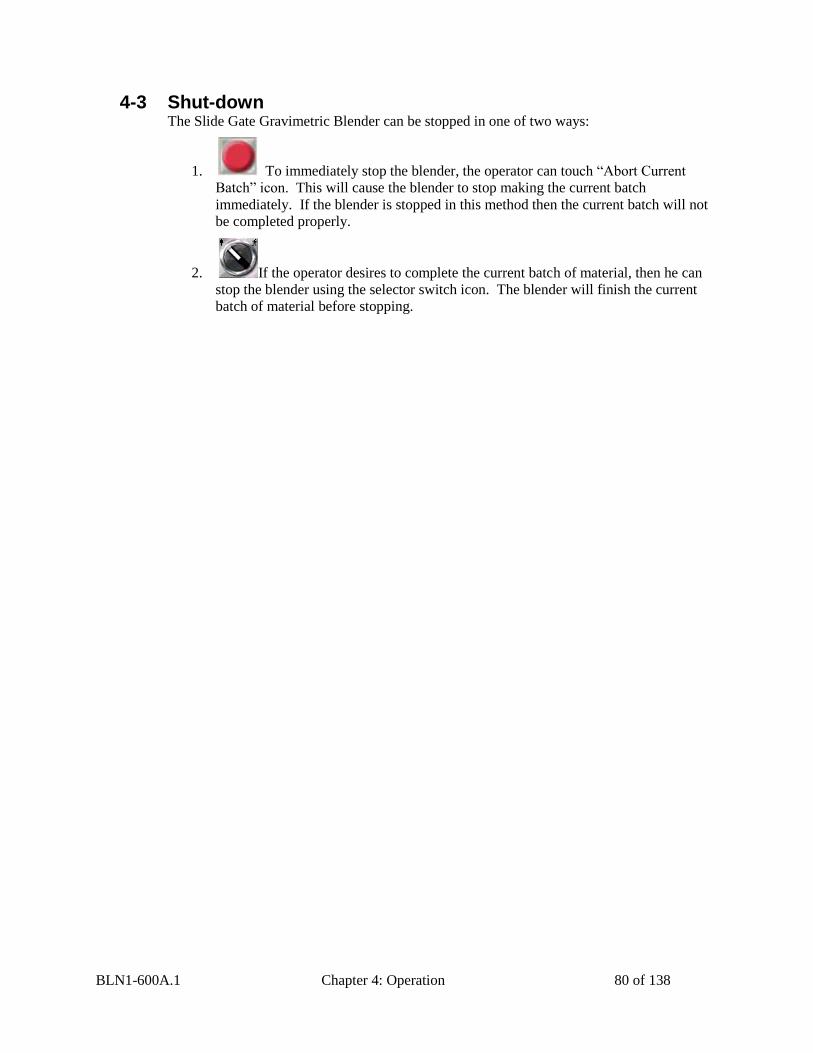
BLN1-600A.1 Chapter 4: Operation 80 of 138
4-3 Shut-down The Slide Gate Gravimetric Blender can be stopped in one of two ways:
1. To immediately stop the blender, the operator can touch “Abort Current
Batch” icon. This will cause the blender to stop making the current batch
immediately. If the blender is stopped in this method then the current batch will not
be completed properly.
2. If the operator desires to complete the current batch of material, then he can
stop the blender using the selector switch icon. The blender will finish the current
batch of material before stopping.
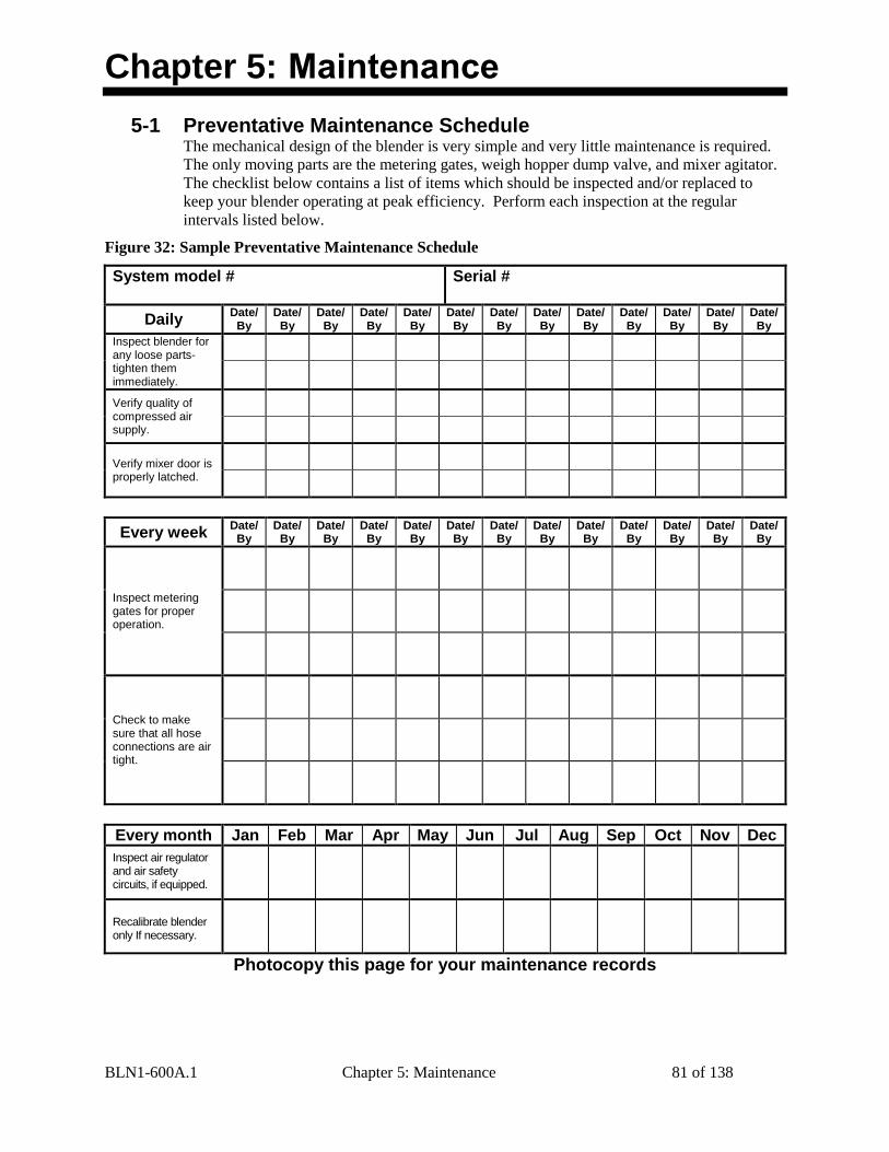
BLN1-600A.1 Chapter 5: Maintenance 81 of 138
Chapter 5: Maintenance
5-1 Preventative Maintenance Schedule The mechanical design of the blender is very simple and very little maintenance is required.
The only moving parts are the metering gates, weigh hopper dump valve, and mixer agitator.
The checklist below contains a list of items which should be inspected and/or replaced to
keep your blender operating at peak efficiency. Perform each inspection at the regular
intervals listed below.
Figure 32: Sample Preventative Maintenance Schedule
System model #
Serial #
Daily Date/
By Date/
By Date/
By Date/
By Date/
By Date/
By Date/
By Date/
By Date/
By Date/
By Date/
By Date/
By Date/
By
Inspect blender for any loose parts-tighten them immediately.
Verify quality of compressed air supply.
Verify mixer door is properly latched.
Every week Date/
By Date/
By Date/
By Date/
By Date/
By Date/
By Date/
By Date/
By Date/
By Date/
By Date/
By Date/
By Date/
By
Inspect metering gates for proper operation.
Check to make sure that all hose connections are air tight.
Every month Jan Feb Mar Apr May Jun Jul Aug Sep Oct Nov Dec
Inspect air regulator and air safety circuits, if equipped.
Recalibrate blender only If necessary.
Photocopy this page for your maintenance records
BLN1-600A.1 Chapter 5: Maintenance 82 of 138
5-2 Preventative Maintenance Our blenders need periodic maintenance to provide long dependable service. Check these
elements regularly:
Check functionality of safety circuit daily.
Maintain proper air pressure and drain water from trap assembly on regulator – as
required.
Periodically lubricate slide gate rails.
Always remove plug and disconnect power before servicing blender.
Always read operating manual before operating or servicing blender.
For gear boxes on BD, SGBD, and RAM units with right angle gear boxes:
Change oil after initial break-in period of 250 hours of operation and at 2500 hours of
operation or 6 month intervals after break-in period.
Recommended oil is Mobil SHC 634 Synthetic oil. 5 gal P/N: OIL0041
Part Description Part Number Oil Capacity
(Fluid Ounces)
4000/6000 Right Angle Reducer
51415 13
160.00280.00 11
RAM 51183 4
BLN1-600A.1 Chapter 5: Maintenance 83 of 138
5-3 Corrective Maintenance Electrical
This section is designed to give the operator an overview of the electrical system that controls
the Batch blending system. Since the blender’s control panel is a self-contained pluggable
item, seldom will a maintenance person be required to enter the control panel. For purposes
of understanding the system, it is advisable that the maintenance personnel be familiar with
not only the internal workings of the control panel, but also with the input and output signals
to the Batch blender.
This section includes the following:
Internal components of the control panel
Input signal to the control panel
Output signals from the control panel
Internal Components of the Control Panel
This section describes the internal components of the Batch blending system control panel. It
is not the intent of this section to completely familiarize the reader with the details on
industrial control panel construction or standards, but simply to familiarize the reader with
the major components inside the control panel.
The customer must supply 120-240/1/60 or 110-220/1/50 voltage via wires L1 & L2 (N).
Please insure that the earth ground connection is properly connected to an established earth
ground.
“Power on” is indicated by a lighted on/off selector switch.
“Slide gate below mixer” switch controls position of optional slide gate.
“Safety Active” light displays status of safety interlock circuit.
Audible alarm horn alerts operator to blender fault.
See Installation Packet supplied with unit for complete electrical schematics.
BLN1-600A.1 Chapter 5: Maintenance 84 of 138
Input Signals to Programmable Controller
The Batch blending system has two main input signals that it uses from the blending process:
the mix hopper high level signal and the weigh hopper load cells. This, of course, does not
include the operator touchscreen input.
The mix hopper high level signal is generated by a proximity level sensor located in the right
hand portion of the mixer chamber (viewing from the mixer door).
Load cells require +10 volts DC to operate. This is known as the load cell’s excitation
voltage.
Output Signals from Programmable Controller
The Batch blending system uses several output control signals to control the process. All of
these are very similar in nature, the first of which is the mixer motor control.
The mixer motor is controlled by a PLC output.
The weigh hopper dump valve output functions similar to the mix motor output. Please refer
back to the wiring diagram. The origin of the weigh hopper dump signal is a PLC output.
The auger motor outputs are driven from a control output from the PLC.
Each blending system includes an auxiliary customer alarm output. This dry contact can be
used to switch a remote alarm signal.
The customer alarm output is provided to actuate or energize a variety of alarm horns,
buzzers, strobe lights, and beacons. These are normally provided by the customer, and
care will have to be exercised not to exceed the maximum current draw (3 amp
maximum). The contacts will close whenever the control detects a fault that will somehow
inhibit the blending system from properly blending the material.
The customer alarm contact is open if the panel control power is turned off.
This contact is for use with a customer supplied alarm device as described
above.
The alarm contact has a maximum load of 3 amps.
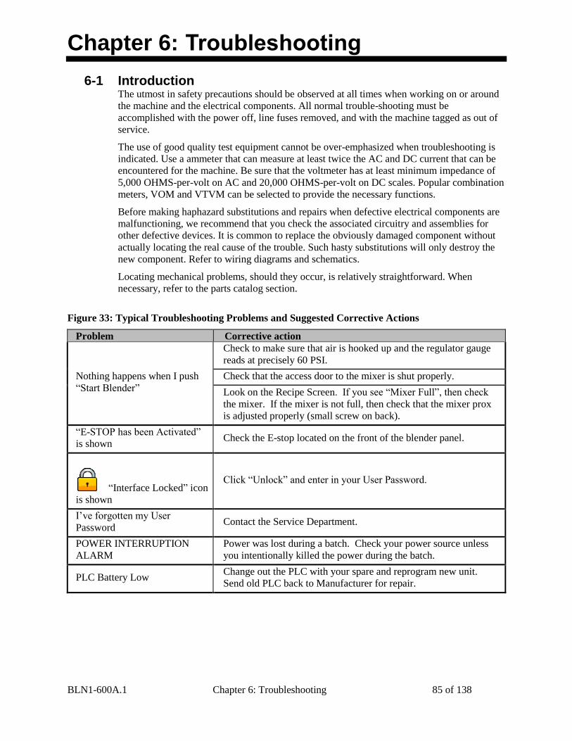
BLN1-600A.1 Chapter 6: Troubleshooting 85 of 138
Chapter 6: Troubleshooting
6-1 Introduction The utmost in safety precautions should be observed at all times when working on or around
the machine and the electrical components. All normal trouble-shooting must be
accomplished with the power off, line fuses removed, and with the machine tagged as out of
service.
The use of good quality test equipment cannot be over-emphasized when troubleshooting is
indicated. Use a ammeter that can measure at least twice the AC and DC current that can be
encountered for the machine. Be sure that the voltmeter has at least minimum impedance of
5,000 OHMS-per-volt on AC and 20,000 OHMS-per-volt on DC scales. Popular combination
meters, VOM and VTVM can be selected to provide the necessary functions.
Before making haphazard substitutions and repairs when defective electrical components are
malfunctioning, we recommend that you check the associated circuitry and assemblies for
other defective devices. It is common to replace the obviously damaged component without
actually locating the real cause of the trouble. Such hasty substitutions will only destroy the
new component. Refer to wiring diagrams and schematics.
Locating mechanical problems, should they occur, is relatively straightforward. When
necessary, refer to the parts catalog section.
Figure 33: Typical Troubleshooting Problems and Suggested Corrective Actions
Problem Corrective action
Nothing happens when I push
“Start Blender”
Check to make sure that air is hooked up and the regulator gauge
reads at precisely 60 PSI.
Check that the access door to the mixer is shut properly.
Look on the Recipe Screen. If you see “Mixer Full”, then check
the mixer. If the mixer is not full, then check that the mixer prox
is adjusted properly (small screw on back).
“E-STOP has been Activated”
is shown Check the E-stop located on the front of the blender panel.
“Interface Locked” icon
is shown
Click “Unlock” and enter in your User Password.
I’ve forgotten my User
Password Contact the Service Department.
POWER INTERRUPTION
ALARM
Power was lost during a batch. Check your power source unless
you intentionally killed the power during the batch.
PLC Battery Low Change out the PLC with your spare and reprogram new unit.
Send old PLC back to Manufacturer for repair.
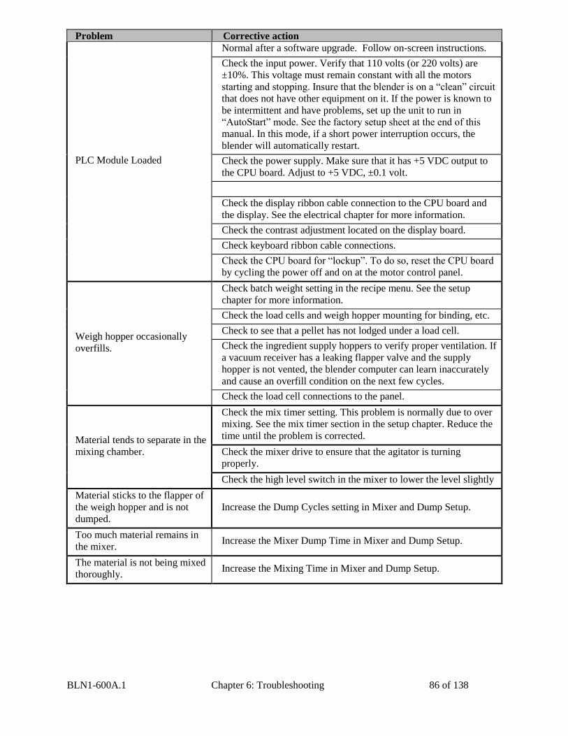
BLN1-600A.1 Chapter 6: Troubleshooting 86 of 138
Problem Corrective action
PLC Module Loaded
Normal after a software upgrade. Follow on-screen instructions.
Check the input power. Verify that 110 volts (or 220 volts) are
±10%. This voltage must remain constant with all the motors
starting and stopping. Insure that the blender is on a “clean” circuit
that does not have other equipment on it. If the power is known to
be intermittent and have problems, set up the unit to run in
“AutoStart” mode. See the factory setup sheet at the end of this
manual. In this mode, if a short power interruption occurs, the
blender will automatically restart.
Check the power supply. Make sure that it has +5 VDC output to
the CPU board. Adjust to +5 VDC, ±0.1 volt.
Check the display ribbon cable connection to the CPU board and
the display. See the electrical chapter for more information.
Check the contrast adjustment located on the display board.
Check keyboard ribbon cable connections.
Check the CPU board for “lockup”. To do so, reset the CPU board
by cycling the power off and on at the motor control panel.
Weigh hopper occasionally
overfills.
Check batch weight setting in the recipe menu. See the setup
chapter for more information.
Check the load cells and weigh hopper mounting for binding, etc.
Check to see that a pellet has not lodged under a load cell.
Check the ingredient supply hoppers to verify proper ventilation. If
a vacuum receiver has a leaking flapper valve and the supply
hopper is not vented, the blender computer can learn inaccurately
and cause an overfill condition on the next few cycles.
Check the load cell connections to the panel.
Material tends to separate in the
mixing chamber.
Check the mix timer setting. This problem is normally due to over
mixing. See the mix timer section in the setup chapter. Reduce the
time until the problem is corrected.
Check the mixer drive to ensure that the agitator is turning
properly.
Check the high level switch in the mixer to lower the level slightly
Material sticks to the flapper of
the weigh hopper and is not
dumped.
Increase the Dump Cycles setting in Mixer and Dump Setup.
Too much material remains in
the mixer. Increase the Mixer Dump Time in Mixer and Dump Setup.
The material is not being mixed
thoroughly. Increase the Mixing Time in Mixer and Dump Setup.
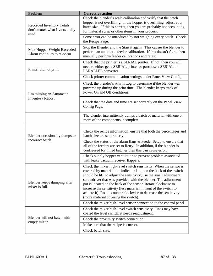
BLN1-600A.1 Chapter 6: Troubleshooting 87 of 138
Problem Corrective action
Recorded Inventory Totals
don’t match what I’ve actually
used
Check the blender’s scale calibration and verify that the batch
hopper is not overfilling. If the hopper is overfilling, adjust your
batch size. If this is correct, then you are probably not accounting
for material scrap or other items in your process.
Some error can be introduced by not weighing every batch. Check
the Recipe Page.
Max Hopper Weight Exceeded
Alarm continues to re-occur.
Stop the Blender and the Start it again. This causes the blender to
perform an automatic feeder calibration. If this doesn’t fix it, then
manually perform feeder calibrations and retest.
Printer did not print
Check that the printer is a SERIAL printer. If not, then you will
need to either get a SERIAL printer or purchase a SERIAL to
PARALLEL converter.
Check printer communication settings under Panel View Config.
I’m missing an Automatic
Inventory Report
Check the blender’s Alarm Log to determine if the blender was
powered up during the print time. The blender keeps track of
Power On and Off conditions.
Check that the date and time are set correctly on the Panel View
Config Page.
Blender occasionally dumps an
incorrect batch.
The blender intermittently dumps a batch of material with one or
more of the components incomplete.
Check the recipe information; ensure that both the percentages and
batch size are set properly.
Check the status of the alarm flags & Feeder Setup to ensure that
all of the feeders are set to Retry. In addition, if the blender is
configured for timed batches then this can cause error.
Check supply hopper ventilation to prevent problem associated
with leaky vacuum receiver flappers.
Blender keeps dumping after
mixer is full.
Check the mixer high-level switch sensitivity. When the sensor is
covered by material, the indicator lamp on the back of the switch
should be lit. To adjust the sensitivity, use the small adjustment
screwdriver that was provided with the blender. The adjustment
pot is located on the back of the sensor. Rotate clockwise to
increase the sensitivity (less material in front of the switch to
actuate it). Rotate counter clockwise to decrease the sensitivity
(more material covering the switch).
Check the mixer high-level sensor connection to the control panel.
Blender will not batch with
empty mixer.
Check the mixer high-level switch sensitivity. Fines may have
coated the level switch; it needs readjustment.
Check the proximity switch connection.
Make sure that the recipe is correct.
Check batch size.
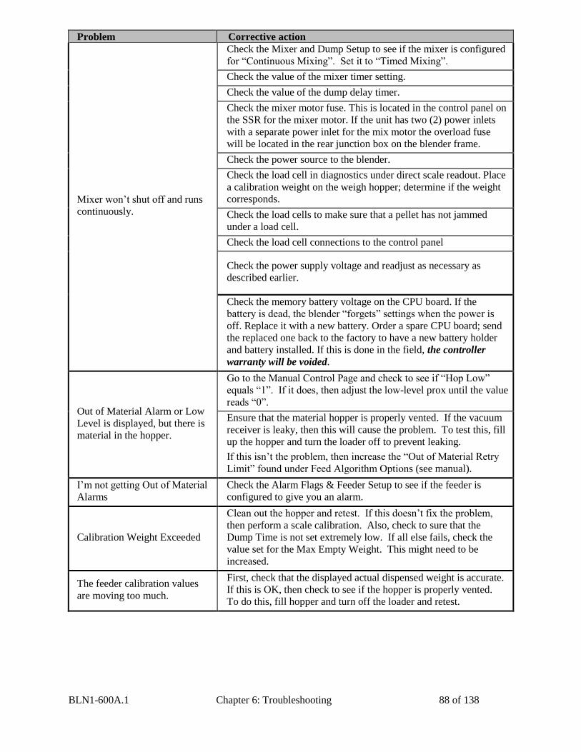
BLN1-600A.1 Chapter 6: Troubleshooting 88 of 138
Problem Corrective action
Mixer won’t shut off and runs
continuously.
Check the Mixer and Dump Setup to see if the mixer is configured
for “Continuous Mixing”. Set it to “Timed Mixing”.
Check the value of the mixer timer setting.
Check the value of the dump delay timer.
Check the mixer motor fuse. This is located in the control panel on
the SSR for the mixer motor. If the unit has two (2) power inlets
with a separate power inlet for the mix motor the overload fuse
will be located in the rear junction box on the blender frame.
Check the power source to the blender.
Check the load cell in diagnostics under direct scale readout. Place
a calibration weight on the weigh hopper; determine if the weight
corresponds.
Check the load cells to make sure that a pellet has not jammed
under a load cell.
Check the load cell connections to the control panel
Check the power supply voltage and readjust as necessary as
described earlier.
Check the memory battery voltage on the CPU board. If the
battery is dead, the blender “forgets” settings when the power is
off. Replace it with a new battery. Order a spare CPU board; send
the replaced one back to the factory to have a new battery holder
and battery installed. If this is done in the field, the controller
warranty will be voided.
Out of Material Alarm or Low
Level is displayed, but there is
material in the hopper.
Go to the Manual Control Page and check to see if “Hop Low”
equals “1”. If it does, then adjust the low-level prox until the value
reads “0”.
Ensure that the material hopper is properly vented. If the vacuum
receiver is leaky, then this will cause the problem. To test this, fill
up the hopper and turn the loader off to prevent leaking.
If this isn’t the problem, then increase the “Out of Material Retry
Limit” found under Feed Algorithm Options (see manual).
I’m not getting Out of Material
Alarms
Check the Alarm Flags & Feeder Setup to see if the feeder is
configured to give you an alarm.
Calibration Weight Exceeded
Clean out the hopper and retest. If this doesn’t fix the problem,
then perform a scale calibration. Also, check to sure that the
Dump Time is not set extremely low. If all else fails, check the
value set for the Max Empty Weight. This might need to be
increased.
The feeder calibration values
are moving too much.
First, check that the displayed actual dispensed weight is accurate.
If this is OK, then check to see if the hopper is properly vented.
To do this, fill hopper and turn off the loader and retest.
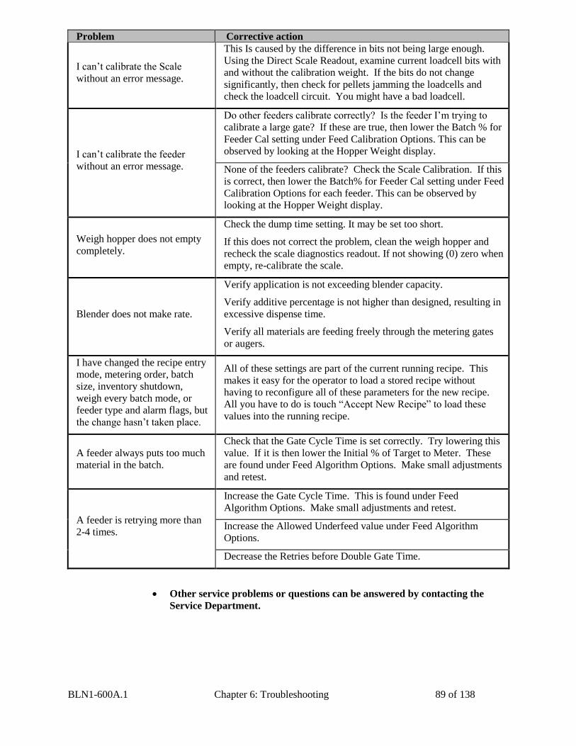
BLN1-600A.1 Chapter 6: Troubleshooting 89 of 138
Problem Corrective action
I can’t calibrate the Scale
without an error message.
This Is caused by the difference in bits not being large enough.
Using the Direct Scale Readout, examine current loadcell bits with
and without the calibration weight. If the bits do not change
significantly, then check for pellets jamming the loadcells and
check the loadcell circuit. You might have a bad loadcell.
I can’t calibrate the feeder
without an error message.
Do other feeders calibrate correctly? Is the feeder I’m trying to
calibrate a large gate? If these are true, then lower the Batch % for
Feeder Cal setting under Feed Calibration Options. This can be
observed by looking at the Hopper Weight display.
None of the feeders calibrate? Check the Scale Calibration. If this
is correct, then lower the Batch% for Feeder Cal setting under Feed
Calibration Options for each feeder. This can be observed by
looking at the Hopper Weight display.
Weigh hopper does not empty
completely.
Check the dump time setting. It may be set too short.
If this does not correct the problem, clean the weigh hopper and
recheck the scale diagnostics readout. If not showing (0) zero when
empty, re-calibrate the scale.
Blender does not make rate.
Verify application is not exceeding blender capacity.
Verify additive percentage is not higher than designed, resulting in
excessive dispense time.
Verify all materials are feeding freely through the metering gates
or augers.
I have changed the recipe entry
mode, metering order, batch
size, inventory shutdown,
weigh every batch mode, or
feeder type and alarm flags, but
the change hasn’t taken place.
All of these settings are part of the current running recipe. This
makes it easy for the operator to load a stored recipe without
having to reconfigure all of these parameters for the new recipe.
All you have to do is touch “Accept New Recipe” to load these
values into the running recipe.
A feeder always puts too much
material in the batch.
Check that the Gate Cycle Time is set correctly. Try lowering this
value. If it is then lower the Initial % of Target to Meter. These
are found under Feed Algorithm Options. Make small adjustments
and retest.
A feeder is retrying more than
2-4 times.
Increase the Gate Cycle Time. This is found under Feed
Algorithm Options. Make small adjustments and retest.
Increase the Allowed Underfeed value under Feed Algorithm
Options.
Decrease the Retries before Double Gate Time.
Other service problems or questions can be answered by contacting the
Service Department.

BLN1-600A.1 Chapter 7: Appendix 90 of 138
Chapter 7: Appendix
7-1 Technical Specifications
Annex B Information
The following design information is provided for your reference:
1. No modifications are allowed to this equipment that could alter the CE compliance
2. Ambient temperature: 40°C – Maximum (104°F)
3. Humidity range: 50% relative humidity
4. Altitude: Up to 1000m above sea level
5. Environment: Clean, dust-free and non-explosive
6. Radiation: None
7. Vibration: Minimal, i.e. machine mounting
8. Special installation requirements: Clean, dry compressed air 1 cfm @ 60 psi (1.7
m³/hr @ 4.14 bar)
9. Allowable voltage fluctuation: +/- 10%
10. Allowable frequency fluctuation: Continuous +/- 1%
Intermittent +/- 2%
11. The addition of an auger feeder (RAM option) for regrind will increase the electrical
supply requirements of a standard blender.
12. Nominal supply voltage: 120-240/1/60 or 110-220/1/50/60 (serial number tag)
13. Earth ground type: TN (system has one point directly earthed through a
protective conductor)
14. Power source should include a neutral power connection.
15. Over-current protection is supplied in the blender, but additional protection should be
supplied by the user. NFPA 70 article 430.24 to 430.26.
16. The plug on the power cord serves as the electrical disconnect device (located 0.6m
to 1.9m above floor).
17. Unit is not equipped with three-phase motors.
18. Blender is not equipped with local lighting.
19. Functional identification
20. Blender is equipped with an optional CE mark or UL label.
21. Blender is supplied with an operating manual in the language of the destination
country.
22. Cable support may be required for power cord, depending on final installation.
23. No one is required to be in the interior of the electrical enclosure during the normal
operation of the unit. Only skilled electricians should be inside the enclosure for
maintenance.
24. Doors can be opened with a screwdriver.
25. Two-hand control is not required or provided.
26. All blenders should be moved around and set in a place with a lift truck or equivalent.
27. There are no frequent repetitive cycles that require manual controlrepetitive
functions are automatic while the blender is operating.
28. An inspection report detailing the functional test is included with the blender.
29. The machine is not equipped with cableless controls.
30. Color-coded (harmonized) power cord is sufficient for proper installation.
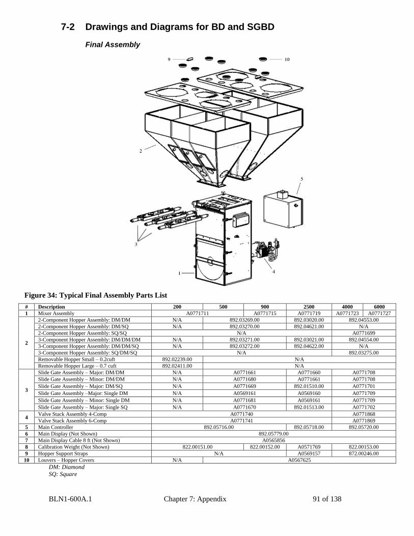
BLN1-600A.1 Chapter 7: Appendix 91 of 138
7-2 Drawings and Diagrams for BD and SGBD
Final Assembly
Figure 34: Typical Final Assembly Parts List
# Description 200 500 900 2500 4000 6000
1 Mixer Assembly A0771711 A0771715 A0771719 A0771723 A0771727
2
2-Component Hopper Assembly: DM/DM N/A 892.03269.00 892.03020.00 892.04553.00
2-Component Hopper Assembly: DM/SQ N/A 892.03270.00 892.04621.00 N/A
2-Component Hopper Assembly: SQ/SQ N/A A0771699
3-Component Hopper Assembly: DM/DM/DM N/A 892.03271.00 892.03021.00 892.04554.00
3-Component Hopper Assembly: DM/DM/SQ N/A 892.03272.00 892.04622.00 N/A
3-Component Hopper Assembly: SQ/DM/SQ N/A 892.03275.00
Removable Hopper Small – 0.2cuft 892.02239.00 N/A
Removable Hopper Large – 0.7 cuft 892.02411.00 N/A
3
Slide Gate Assembly – Major: DM/DM N/A A0771661 A0771660 A0771708
Slide Gate Assembly – Minor: DM/DM N/A A0771680 A0771661 A0771708
Slide Gate Assembly – Major: DM/SQ N/A A0771669 892.01510.00 A0771701
Slide Gate Assembly –Major: Single DM N/A A0569161 A0569160 A0771709
Slide Gate Assembly – Minor: Single DM N/A A0771681 A0569161 A0771709
Slide Gate Assembly – Major: Single SQ N/A A0771670 892.01513.00 A0771702
4 Valve Stack Assembly 4-Comp A0771740 A0771868
Valve Stack Assembly 6-Comp A0771741 A0771869
5 Main Controller 892.05716.00 892.05718.00 892.05720.00
6 Main Display (Not Shown) 892.05779.00
7 Main Display Cable 8 ft (Not Shown) A0565856
8 Calibration Weight (Not Shown) 822.00151.00 822.00152.00 A0571769 822.00153.00
9 Hopper Support Straps N/A A0569157 872.00246.00
10 Louvers – Hopper Covers N/A A0567625
DM: Diamond
SQ: Square
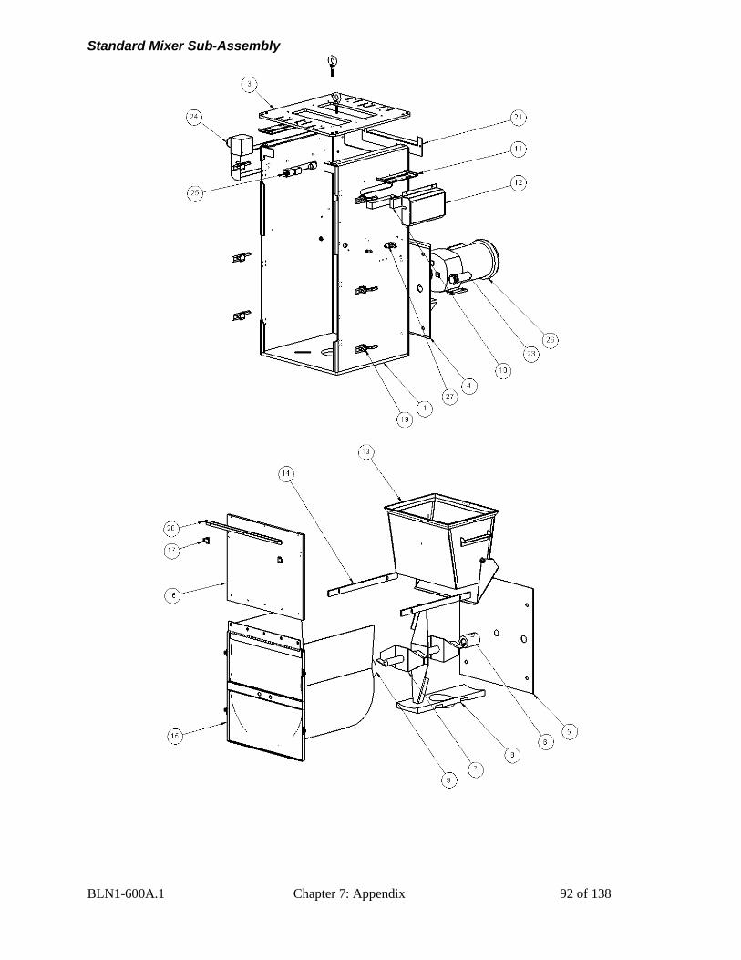
BLN1-600A.1 Chapter 7: Appendix 92 of 138
Standard Mixer Sub-Assembly
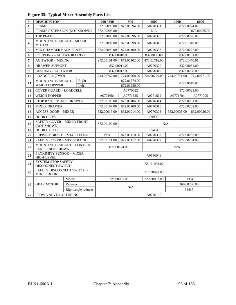
BLN1-600A.1 Chapter 7: Appendix 93 of 138
Figure 35: Typical Mixer Assembly Parts List
# DESCRIPTION 200 / 500 900 2500 4000 6000
1 FRAME 872.00093.00 872.00094.00 A0770301 872.00224.00
2 FRAME EXTENSION (NOT SHOWN) 872.00208.00 N/A 872.00225.00
3 TOP PLATE 872.00095.00 872.00096.00 A0770300 872.00226.00
4 MOUNTING BRACKET – MIXER
MOTOR 872.00097.00 872.00098.00 A0770316 872.01318.00
5 MIX CHAMBER BACK PLATE 872.00099.00 872.00100.00 A0770333 872.00227.00
6 COUPLING – AGITATOR DRIVE 832.00010.00 832.0003.00 832.00181.00
7 AGITATOR – MIXING 872.00101.00 872.00102.00 872.01716.00 872.01470.01
8 DRAWER SUPPORT 832.00011.00 A0770320 832.00034.00
9 BUSHING – AGITATOR 832.00012.00 A0770319 832.00238.00
10 LOADCELL (TWO) 724.00767.00 724.00768.00 724.00770.00 724.00771.00 724.00771.00
11 MOUNTING BRACKET –
WEIGH HOPPPER
Right 872.01774.00 872.00519.00
Left 872.01280.00
12 COVER GUARD – LOADCELL A0770322 872.00521.00
13 WEIGH HOPPER A0771684 A0771685 A0771662 A0771704 A0771705
14 STOP RAIL – MIXER DRAWER 872.00105.00 872.00106.00 A0770314 872.00231.00
15 MIXER DRAWER 872.00107.00 872.00108.00 A0770315 872.00232.00
16 ACCESS DOOR – MIXER 832.00013.00 832.00014.00 A0770303 832.00035.00 832.00036.00
17 DOOR CLIPS 09990
18 SAFETY COVER – MIXER FRONT
(NOT SHOWN) 872.00109.00 N/A
19 DOOR LATCH 35454
20 SUPPORT BRACE – MIXER DOOR N/A 872.00110.00 A0770332 872.00233.00
21 SAFETY COVER – MIXER BACK 872.00111.00 872.00112.00 A0770302 872.00234.00
22 MOUNTING BRACKET – CONTROL
PANEL (NOT SHOWN) 872.00124.00 N/A
23 PROXIMITY SENSOR – MIXER
HIGH-LEVEL A0556548
24 SYSTEM-STOP SAFETY
DISCONNECT SWITCH 721.01058.02
25 SAFETY DISCONNECT SWITCH –
MIXER DOOR 717.00078.00
26 GEAR MOTOR
Motor 720.00001.00 720.00002.00 51354
Reducer N/A
160.00280.00
Right angle reducer 51415
27 FLOW VALVE 1/4" TUBING A0770190
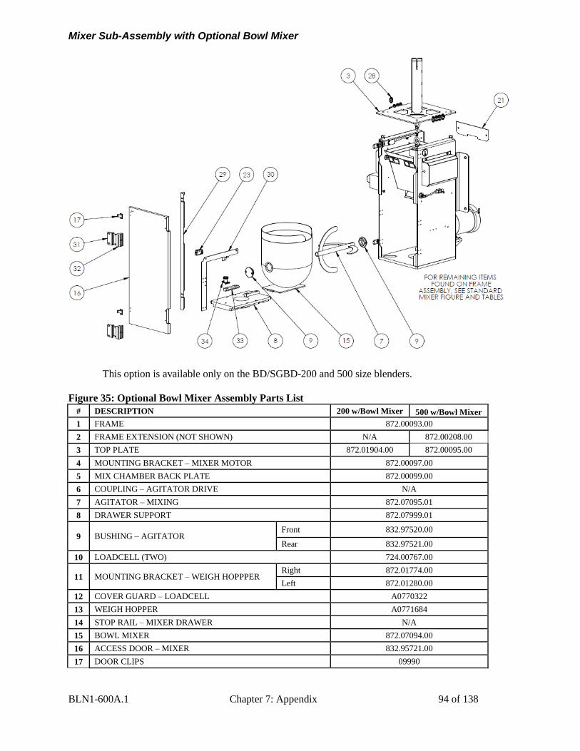
BLN1-600A.1 Chapter 7: Appendix 94 of 138
Mixer Sub-Assembly with Optional Bowl Mixer
This option is available only on the BD/SGBD-200 and 500 size blenders.
Figure 35: Optional Bowl Mixer Assembly Parts List
# DESCRIPTION 200 w/Bowl Mixer 500 w/Bowl Mixer
1 FRAME 872.00093.00
2 FRAME EXTENSION (NOT SHOWN) N/A 872.00208.00
3 TOP PLATE 872.01904.00 872.00095.00
4 MOUNTING BRACKET – MIXER MOTOR 872.00097.00
5 MIX CHAMBER BACK PLATE 872.00099.00
6 COUPLING – AGITATOR DRIVE N/A
7 AGITATOR – MIXING 872.07095.01
8 DRAWER SUPPORT 872.07999.01
9 BUSHING – AGITATOR Front 832.97520.00
Rear 832.97521.00
10 LOADCELL (TWO) 724.00767.00
11 MOUNTING BRACKET – WEIGH HOPPPER Right 872.01774.00
Left 872.01280.00
12 COVER GUARD – LOADCELL A0770322
13 WEIGH HOPPER A0771684
14 STOP RAIL – MIXER DRAWER N/A
15 BOWL MIXER 872.07094.00
16 ACCESS DOOR – MIXER 832.95721.00
17 DOOR CLIPS 09990
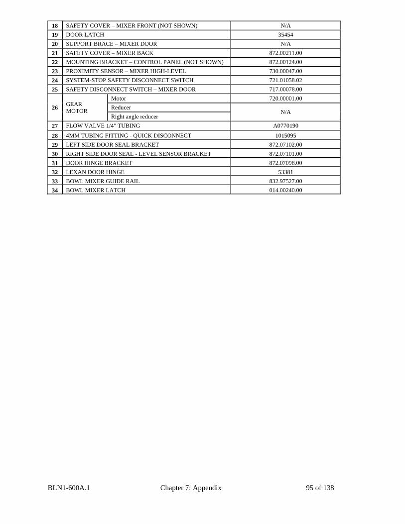
BLN1-600A.1 Chapter 7: Appendix 95 of 138
18 SAFETY COVER – MIXER FRONT (NOT SHOWN) N/A
19 DOOR LATCH 35454
20 SUPPORT BRACE – MIXER DOOR N/A
21 SAFETY COVER – MIXER BACK 872.00211.00
22 MOUNTING BRACKET – CONTROL PANEL (NOT SHOWN) 872.00124.00
23 PROXIMITY SENSOR – MIXER HIGH-LEVEL 730.00047.00
24 SYSTEM-STOP SAFETY DISCONNECT SWITCH 721.01058.02
25 SAFETY DISCONNECT SWITCH – MIXER DOOR 717.00078.00
26 GEAR
MOTOR
Motor 720.00001.00
Reducer N/A
Right angle reducer
27 FLOW VALVE 1/4" TUBING A0770190
28 4MM TUBING FITTING - QUICK DISCONNECT 1015095
29 LEFT SIDE DOOR SEAL BRACKET 872.07102.00
30 RIGHT SIDE DOOR SEAL - LEVEL SENSOR BRACKET 872.07101.00
31 DOOR HINGE BRACKET 872.07098.00
32 LEXAN DOOR HINGE 53381
33 BOWL MIXER GUIDE RAIL 832.97527.00
34 BOWL MIXER LATCH 014.00240.00
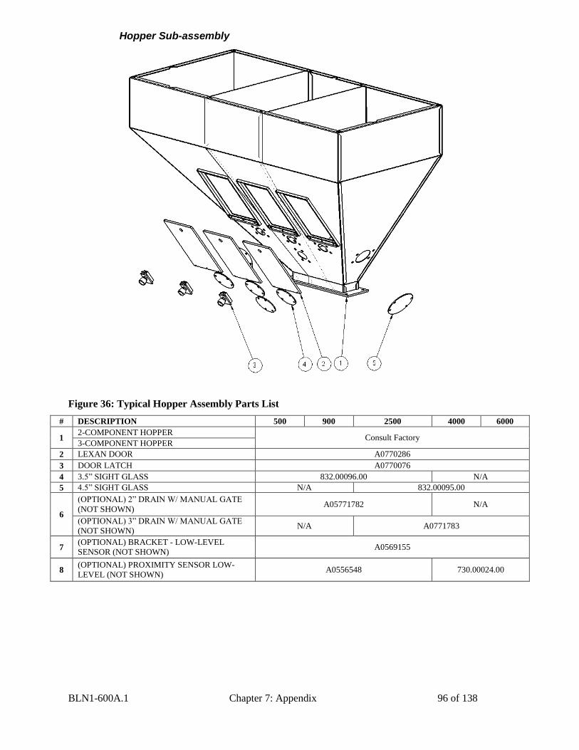
BLN1-600A.1 Chapter 7: Appendix 96 of 138
Hopper Sub-assembly
Figure 36: Typical Hopper Assembly Parts List
# DESCRIPTION 500 900 2500 4000 6000
1 2-COMPONENT HOPPER
Consult Factory 3-COMPONENT HOPPER
2 LEXAN DOOR A0770286
3 DOOR LATCH A0770076
4 3.5” SIGHT GLASS 832.00096.00 N/A
5 4.5” SIGHT GLASS N/A 832.00095.00
6
(OPTIONAL) 2” DRAIN W/ MANUAL GATE
(NOT SHOWN) A05771782 N/A
(OPTIONAL) 3” DRAIN W/ MANUAL GATE
(NOT SHOWN) N/A A0771783
7 (OPTIONAL) BRACKET - LOW-LEVEL
SENSOR (NOT SHOWN) A0569155
8 (OPTIONAL) PROXIMITY SENSOR LOW-
LEVEL (NOT SHOWN) A0556548 730.00024.00
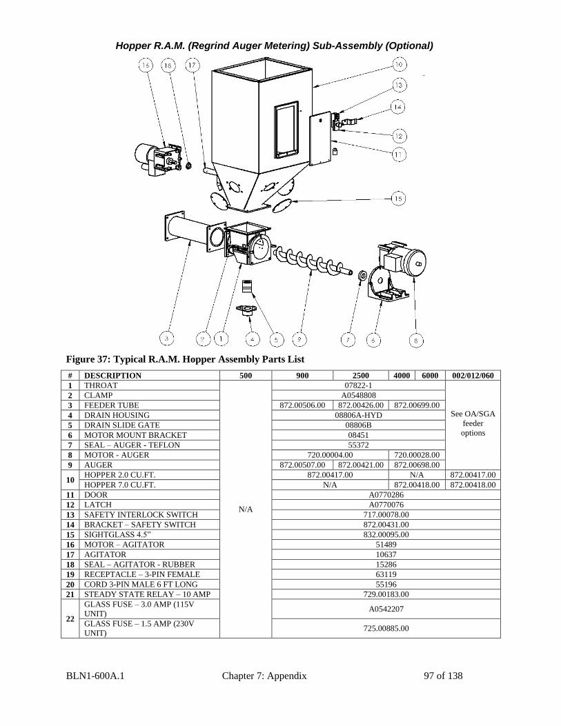
BLN1-600A.1 Chapter 7: Appendix 97 of 138
Hopper R.A.M. (Regrind Auger Metering) Sub-Assembly (Optional)
Figure 37: Typical R.A.M. Hopper Assembly Parts List
# DESCRIPTION 500 900 2500 4000 6000 002/012/060
1 THROAT
N/A
07822-1
See OA/SGA
feeder
options
2 CLAMP A0548808
3 FEEDER TUBE 872.00506.00 872.00426.00 872.00699.00
4 DRAIN HOUSING 08806A-HYD
5 DRAIN SLIDE GATE 08806B
6 MOTOR MOUNT BRACKET 08451
7 SEAL – AUGER - TEFLON 55372
8 MOTOR - AUGER 720.00004.00 720.00028.00
9 AUGER 872.00507.00 872.00421.00 872.00698.00
10 HOPPER 2.0 CU.FT. 872.00417.00 N/A 872.00417.00
HOPPER 7.0 CU.FT. N/A 872.00418.00 872.00418.00
11 DOOR A0770286
12 LATCH A0770076
13 SAFETY INTERLOCK SWITCH 717.00078.00
14 BRACKET – SAFETY SWITCH 872.00431.00
15 SIGHTGLASS 4.5” 832.00095.00
16 MOTOR – AGITATOR 51489
17 AGITATOR 10637
18 SEAL – AGITATOR - RUBBER 15286
19 RECEPTACLE – 3-PIN FEMALE 63119
20 CORD 3-PIN MALE 6 FT LONG 55196
21 STEADY STATE RELAY – 10 AMP 729.00183.00
22
GLASS FUSE – 3.0 AMP (115V
UNIT) A0542207
GLASS FUSE – 1.5 AMP (230V
UNIT) 725.00885.00
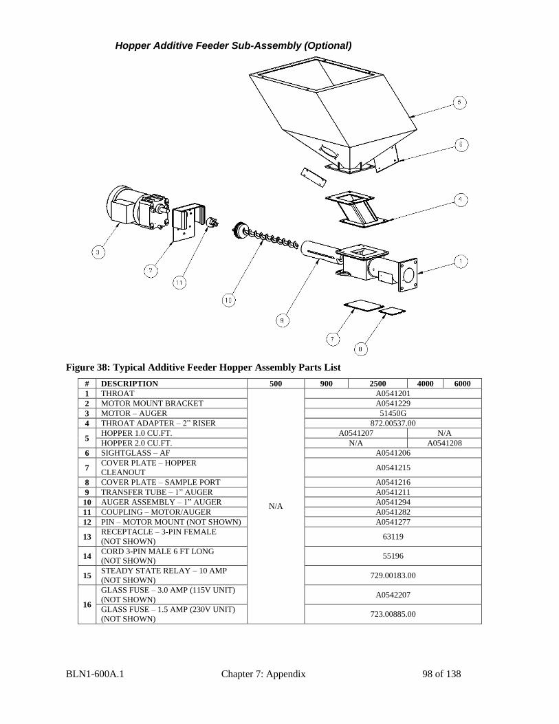
BLN1-600A.1 Chapter 7: Appendix 98 of 138
Hopper Additive Feeder Sub-Assembly (Optional)
Figure 38: Typical Additive Feeder Hopper Assembly Parts List
# DESCRIPTION 500 900 2500 4000 6000
1 THROAT
N/A
A0541201
2 MOTOR MOUNT BRACKET A0541229
3 MOTOR – AUGER 51450G
4 THROAT ADAPTER – 2” RISER 872.00537.00
5 HOPPER 1.0 CU.FT. A0541207 N/A
HOPPER 2.0 CU.FT. N/A A0541208
6 SIGHTGLASS – AF A0541206
7 COVER PLATE – HOPPER
CLEANOUT A0541215
8 COVER PLATE – SAMPLE PORT A0541216
9 TRANSFER TUBE – 1” AUGER A0541211
10 AUGER ASSEMBLY – 1” AUGER A0541294
11 COUPLING – MOTOR/AUGER A0541282
12 PIN – MOTOR MOUNT (NOT SHOWN) A0541277
13 RECEPTACLE – 3-PIN FEMALE
(NOT SHOWN) 63119
14 CORD 3-PIN MALE 6 FT LONG
(NOT SHOWN) 55196
15 STEADY STATE RELAY – 10 AMP
(NOT SHOWN) 729.00183.00
16
GLASS FUSE – 3.0 AMP (115V UNIT)
(NOT SHOWN) A0542207
GLASS FUSE – 1.5 AMP (230V UNIT)
(NOT SHOWN) 723.00885.00
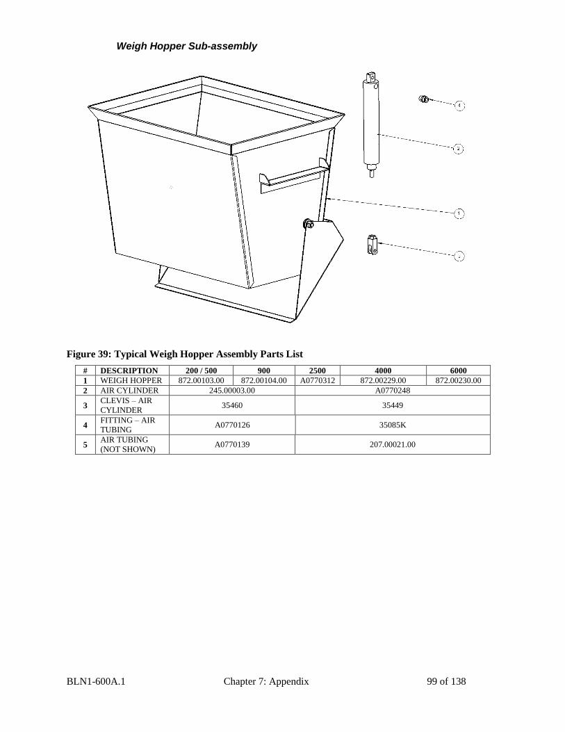
BLN1-600A.1 Chapter 7: Appendix 99 of 138
Weigh Hopper Sub-assembly
Figure 39: Typical Weigh Hopper Assembly Parts List
# DESCRIPTION 200 / 500 900 2500 4000 6000
1 WEIGH HOPPER 872.00103.00 872.00104.00 A0770312 872.00229.00 872.00230.00
2 AIR CYLINDER 245.00003.00 A0770248
3 CLEVIS – AIR
CYLINDER 35460 35449
4 FITTING – AIR
TUBING A0770126 35085K
5 AIR TUBING
(NOT SHOWN) A0770139 207.00021.00
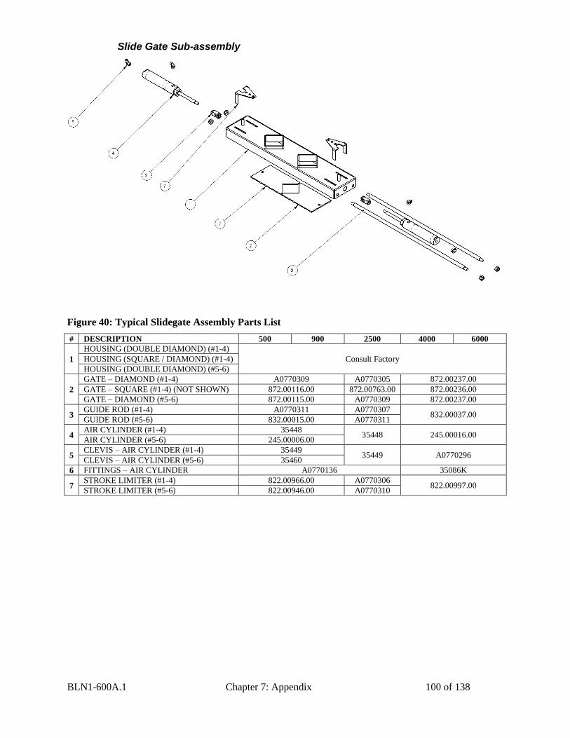
BLN1-600A.1 Chapter 7: Appendix 100 of 138
Slide Gate Sub-assembly
Figure 40: Typical Slidegate Assembly Parts List
# DESCRIPTION 500 900 2500 4000 6000
1
HOUSING (DOUBLE DIAMOND) (#1-4)
Consult Factory HOUSING (SQUARE / DIAMOND) (#1-4)
HOUSING (DOUBLE DIAMOND) (#5-6)
2
GATE – DIAMOND (#1-4) A0770309 A0770305 872.00237.00
GATE – SQUARE (#1-4) (NOT SHOWN) 872.00116.00 872.00763.00 872.00236.00
GATE – DIAMOND (#5-6) 872.00115.00 A0770309 872.00237.00
3 GUIDE ROD (#1-4) A0770311 A0770307
832.00037.00 GUIDE ROD (#5-6) 832.00015.00 A0770311
4 AIR CYLINDER (#1-4) 35448
35448 245.00016.00 AIR CYLINDER (#5-6) 245.00006.00
5 CLEVIS – AIR CYLINDER (#1-4) 35449
35449 A0770296 CLEVIS – AIR CYLINDER (#5-6) 35460
6 FITTINGS – AIR CYLINDER A0770136 35086K
7 STROKE LIMITER (#1-4) 822.00966.00 A0770306
822.00997.00 STROKE LIMITER (#5-6) 822.00946.00 A0770310
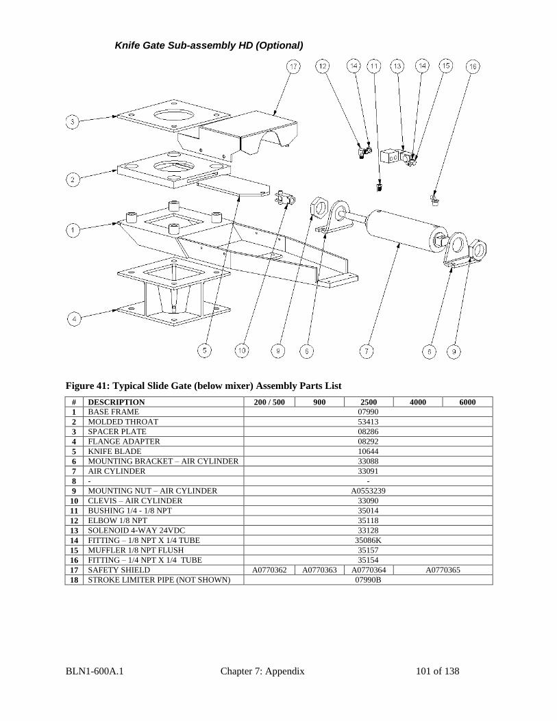
BLN1-600A.1 Chapter 7: Appendix 101 of 138
Knife Gate Sub-assembly HD (Optional)
Figure 41: Typical Slide Gate (below mixer) Assembly Parts List
# DESCRIPTION 200 / 500 900 2500 4000 6000
1 BASE FRAME 07990
2 MOLDED THROAT 53413
3 SPACER PLATE 08286
4 FLANGE ADAPTER 08292
5 KNIFE BLADE 10644
6 MOUNTING BRACKET – AIR CYLINDER 33088
7 AIR CYLINDER 33091
8 - -
9 MOUNTING NUT – AIR CYLINDER A0553239
10 CLEVIS – AIR CYLINDER 33090
11 BUSHING 1/4 - 1/8 NPT 35014
12 ELBOW 1/8 NPT 35118
13 SOLENOID 4-WAY 24VDC 33128
14 FITTING – 1/8 NPT X 1/4 TUBE 35086K
15 MUFFLER 1/8 NPT FLUSH 35157
16 FITTING – 1/4 NPT X 1/4 TUBE 35154
17 SAFETY SHIELD A0770362 A0770363 A0770364 A0770365
18 STROKE LIMITER PIPE (NOT SHOWN) 07990B
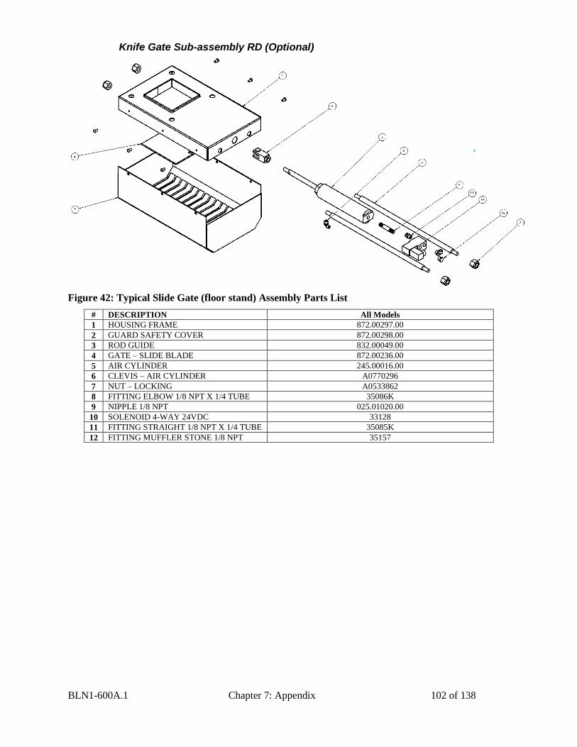
BLN1-600A.1 Chapter 7: Appendix 102 of 138
Knife Gate Sub-assembly RD (Optional)
Figure 42: Typical Slide Gate (floor stand) Assembly Parts List
# DESCRIPTION All Models
1 HOUSING FRAME 872.00297.00
2 GUARD SAFETY COVER 872.00298.00
3 ROD GUIDE 832.00049.00
4 GATE – SLIDE BLADE 872.00236.00
5 AIR CYLINDER 245.00016.00
6 CLEVIS – AIR CYLINDER A0770296
7 NUT – LOCKING A0533862
8 FITTING ELBOW 1/8 NPT X 1/4 TUBE 35086K
9 NIPPLE 1/8 NPT 025.01020.00
10 SOLENOID 4-WAY 24VDC 33128
11 FITTING STRAIGHT 1/8 NPT X 1/4 TUBE 35085K
12 FITTING MUFFLER STONE 1/8 NPT 35157
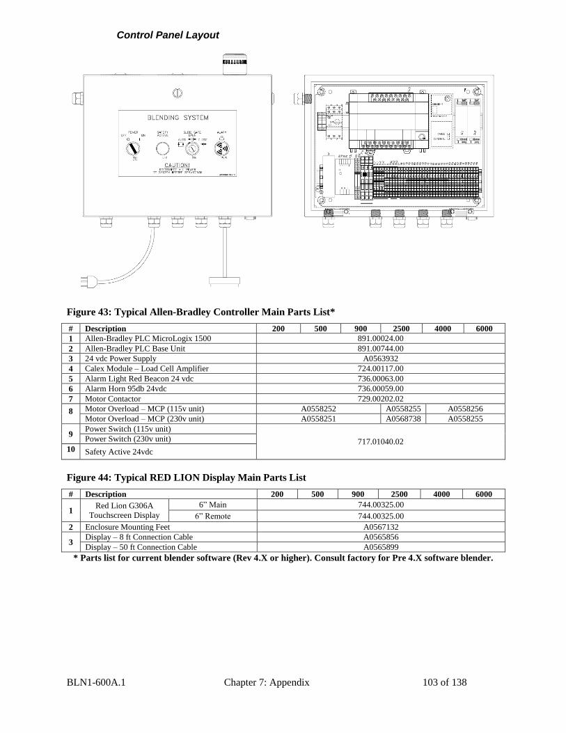
BLN1-600A.1 Chapter 7: Appendix 103 of 138
Control Panel Layout
Figure 43: Typical Allen-Bradley Controller Main Parts List*
# Description 200 500 900 2500 4000 6000
1 Allen-Bradley PLC MicroLogix 1500 891.00024.00
2 Allen-Bradley PLC Base Unit 891.00744.00
3 24 vdc Power Supply A0563932
4 Calex Module – Load Cell Amplifier 724.00117.00
5 Alarm Light Red Beacon 24 vdc 736.00063.00
6 Alarm Horn 95db 24vdc 736.00059.00
7 Motor Contactor 729.00202.02
8 Motor Overload – MCP (115v unit) A0558252 A0558255 A0558256
Motor Overload – MCP (230v unit) A0558251 A0568738 A0558255
9 Power Switch (115v unit)
717.01040.02 Power Switch (230v unit)
10 Safety Active 24vdc
Figure 44: Typical RED LION Display Main Parts List
# Description 200 500 900 2500 4000 6000
1 Red Lion G306A
Touchscreen Display
6” Main 744.00325.00
6” Remote 744.00325.00
2 Enclosure Mounting Feet A0567132
3 Display – 8 ft Connection Cable A0565856
Display – 50 ft Connection Cable A0565899
* Parts list for current blender software (Rev 4.X or higher). Consult factory for Pre 4.X software blender.
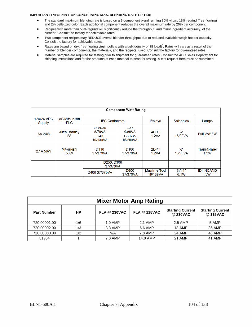
BLN1-600A.1 Chapter 7: Appendix 104 of 138
IMPORTANT INFORMATION CONCERNING MAX. BLENDING RATE LISTED:
The standard maximum blending rate is based on a 3-component blend running 80% virgin, 18% regrind (free-flowing) and 2% pelletized color. Each additional component reduces the overall maximum rate by 20% per component.
Recipes with more than 50% regrind will significantly reduce the throughput, and minor ingredient accuracy, of the blender. Consult the factory for achievable rates.
Two component recipes may REDUCE overall blender throughput due to reduced available weigh hopper capacity. Consult the factory for achievable rates.
Rates are based on dry, free-flowing virgin pellets with a bulk density of 35 lbs./ft3. Rates will vary as a result of the
number of blender components, the materials, and the recipe(s) used. Consult the factory for guaranteed rates.
Material samples are required for testing prior to shipment for guaranteed rates. Consult the AEC Sales Department for shipping instructions and for the amounts of each material to send for testing. A test request form must be submitted,
Mixer Motor Amp Rating
Part Number HP FLA @ 230VAC FLA @ 115VAC Starting Current
@ 230VAC Starting Current
@ 115VAC
720.00001.00 1/6 1.0 AMP 2.1 AMP 2.5 AMP 5 AMP
720.00002.00 1/3 3.3 AMP 6.6 AMP 18 AMP 36 AMP
720.00030.00 1/2 N/A 7.8 AMP 24 AMP 48 AMP
51354 1 7.0 AMP 14.0 AMP 21 AMP 41 AMP
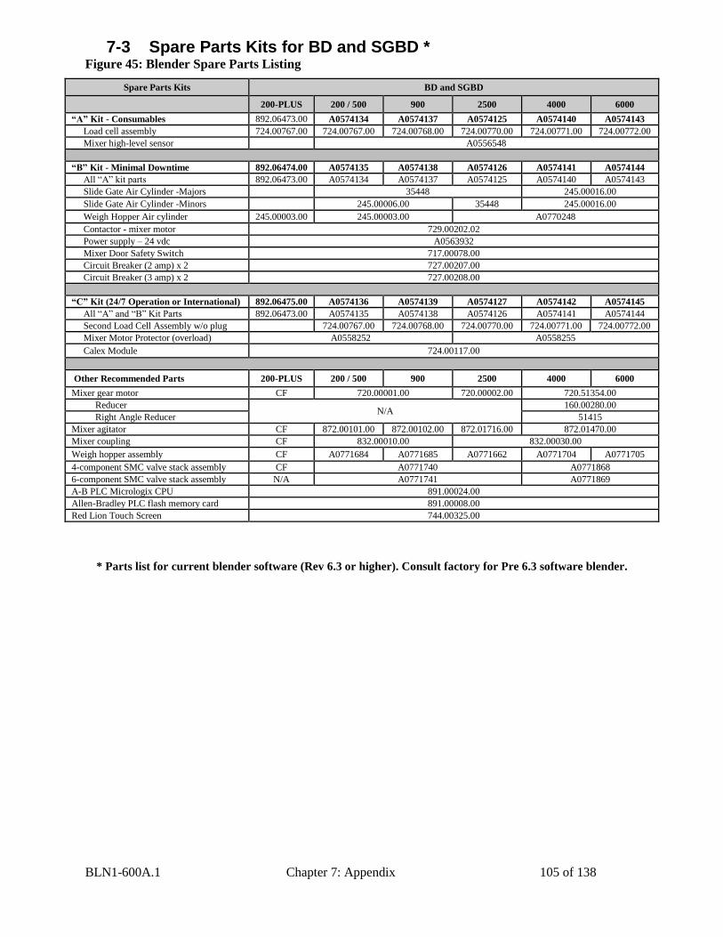
BLN1-600A.1 Chapter 7: Appendix 105 of 138
7-3 Spare Parts Kits for BD and SGBD * Figure 45: Blender Spare Parts Listing
Spare Parts Kits BD and SGBD
200-PLUS 200 / 500 900 2500 4000 6000
“A” Kit - Consumables 892.06473.00 A0574134 A0574137 A0574125 A0574140 A0574143
Load cell assembly 724.00767.00 724.00767.00 724.00768.00 724.00770.00 724.00771.00 724.00772.00
Mixer high-level sensor A0556548
“B” Kit - Minimal Downtime 892.06474.00 A0574135 A0574138 A0574126 A0574141 A0574144
All “A” kit parts 892.06473.00 A0574134 A0574137 A0574125 A0574140 A0574143
Slide Gate Air Cylinder -Majors 35448 245.00016.00
Slide Gate Air Cylinder -Minors 245.00006.00 35448 245.00016.00
Weigh Hopper Air cylinder 245.00003.00 245.00003.00 A0770248
Contactor - mixer motor 729.00202.02
Power supply – 24 vdc A0563932
Mixer Door Safety Switch 717.00078.00
Circuit Breaker (2 amp) x 2 727.00207.00
Circuit Breaker (3 amp) x 2 727.00208.00
“C” Kit (24/7 Operation or International) 892.06475.00 A0574136 A0574139 A0574127 A0574142 A0574145
All “A” and “B” Kit Parts 892.06473.00 A0574135 A0574138 A0574126 A0574141 A0574144
Second Load Cell Assembly w/o plug 724.00767.00 724.00768.00 724.00770.00 724.00771.00 724.00772.00
Mixer Motor Protector (overload) A0558252 A0558255
Calex Module 724.00117.00
Other Recommended Parts 200-PLUS 200 / 500 900 2500 4000 6000
Mixer gear motor CF 720.00001.00 720.00002.00 720.51354.00
Reducer N/A
160.00280.00
Right Angle Reducer 51415
Mixer agitator CF 872.00101.00 872.00102.00 872.01716.00 872.01470.00
Mixer coupling CF 832.00010.00 832.00030.00
Weigh hopper assembly CF A0771684 A0771685 A0771662 A0771704 A0771705
4-component SMC valve stack assembly CF A0771740 A0771868
6-component SMC valve stack assembly N/A A0771741 A0771869
A-B PLC Micrologix CPU 891.00024.00
Allen-Bradley PLC flash memory card 891.00008.00
Red Lion Touch Screen 744.00325.00
* Parts list for current blender software (Rev 6.3 or higher). Consult factory for Pre 6.3 software blender.
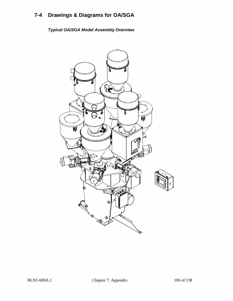
BLN1-600A.1 Chapter 7: Appendix 106 of 138
7-4 Drawings & Diagrams for OA/SGA
Typical OA/SGA Model Assembly Overview
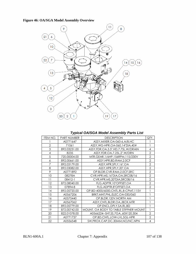
BLN1-600A.1 Chapter 7: Appendix 107 of 138
Figure 46: OA/SGA Model Assembly Overview
Typical OA/SGA Model Assembly Parts List
ITEM NO. PART NUMBER DESCRIPTION QTY.
1 A0771647 ASSY,MIXER,OA-060-6,A/B,HC 1
2 71061 ASSY,WG-HPR,OA-060,14"DIA,40# 1
3 892.03231.00 ASSY,FDR,OA,3.5",HD,7.75L,W/DRAIN 4
4 8235 ASSY,FDR,OA,7.25L,2",W/DRN 2
5 720.00004.00 MTR,GEAR,1/6HP,156RPM,115/230V 2
6 892.00661.00 ASSY,HPR,BD,RAM,2.0CF 2
7 892.03179.00 ASSY,HPR,SPLY,16",OA 2
8 892.03082.00 ASSY,HPR,SPLY,20",OA 2
9 A0771892 OP,BLDR,CVR,RAM,2.0CF,SRC 2
10 08278A CVR,HPR,MS,16"DIA,OA,SRC08/16 2
11 08412-1 CVR,HPR,MS,20"DIA,SRC08/16 2
12 872.08040.00 FLG,ADPTR,10"OFFSET,OA 2
13 07894-8 FLG,ADPTR,8"OFFSET,OA 2
14 892.05720.00 OP,BD-4000/6000,CNTL,RL,8-CPMT,115V 1
15 A0567206 BRKT,MNT,PNL,ELEC,OA-030/060 1
16 A0575440 OP,BLDR,120V,NORTH AM 1
17 A0567062 ASSY,CNTL,BLDR,OA,JBOX,MTR 1
18 892.05779.00 OP,ENCL,DPLY,SA,RL,BD 1
19 872.00742.00 MOUNT, OA BODY TO TABLE STIFFNER MOUNT 1
20 822.01078.00 A0566224--SHT,SS,7GA.,60X120,304 2
21 A0771737 OP,BD,CNTL,LOW-LVL,SGL-HPR 2
22 A0556548 SW,PROX,CAP,DC,30MM,NO/NC,NPN 4
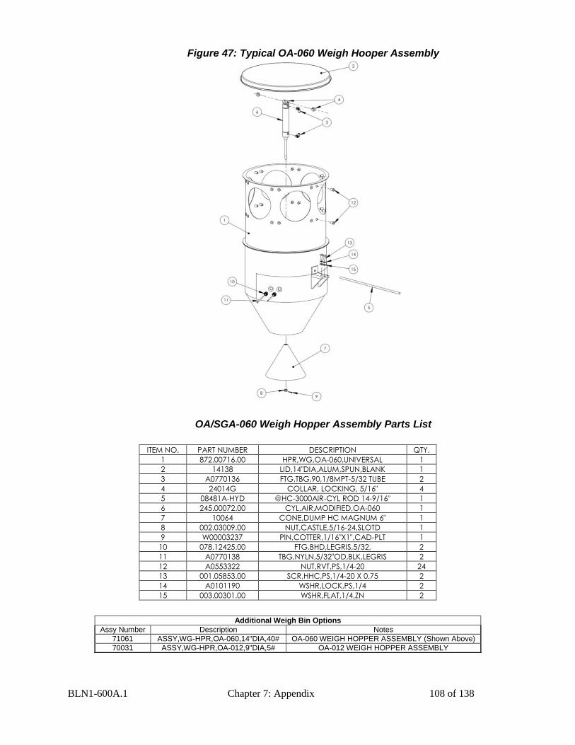
BLN1-600A.1 Chapter 7: Appendix 108 of 138
Figure 47: Typical OA-060 Weigh Hooper Assembly
OA/SGA-060 Weigh Hopper Assembly Parts List
ITEM NO. PART NUMBER DESCRIPTION QTY.
1 872.00716.00 HPR,WG,OA-060,UNIVERSAL 1
2 14138 LID,14"DIA,ALUM,SPUN,BLANK 1
3 A0770136 FTG,TBG,90,1/8MPT-5/32 TUBE 2
4 24014G COLLAR, LOCKING, 5/16" 4
5 08481A-HYD @HC-3000AIR-CYL ROD 14-9/16" 1
6 245.00072.00 CYL,AIR,MODIFIED,OA-060 1
7 10064 CONE,DUMP HC MAGNUM 6" 1
8 002.03009.00 NUT,CASTLE,5/16-24,SLOTD 1
9 W00003237 PIN,COTTER,1/16"X1",CAD-PLT 1
10 078.12425.00 FTG,BHD,LEGRIS,5/32, 2
11 A0770138 TBG,NYLN,5/32"OD,BLK,LEGRIS 2
12 A0553322 NUT,RVT,PS,1/4-20 24
13 001.05853.00 SCR,HHC,PS,1/4-20 X 0.75 2
14 A0101190 WSHR,LOCK,PS,1/4 2
15 003.00301.00 WSHR,FLAT,1/4,ZN 2
Additional Weigh Bin Options
Assy Number Description Notes
71061 ASSY,WG-HPR,OA-060,14"DIA,40# OA-060 WEIGH HOPPER ASSEMBLY (Shown Above)
70031 ASSY,WG-HPR,OA-012,9"DIA,5# OA-012 WEIGH HOPPER ASSEMBLY
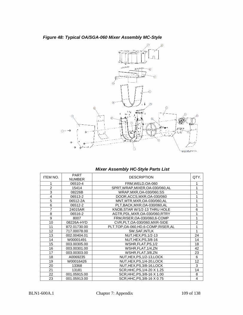
BLN1-600A.1 Chapter 7: Appendix 109 of 138
Figure 48: Typical OA/SGA-060 Mixer Assembly MC-Style
Mixer Assembly HC-Style Parts List
ITEM NO. PART
NUMBER DESCRIPTION QTY.
1 06510-4 FRM,WELD,OA-060 1
2 15414 SPRT,WRAP,MIXER,OA-030/060,AL 1
3 08226B WRAP,MXR,OA-030/060,SS 1
4 06513-2 DOOR,ACCS,MXR,OA-030/060 1
5 06512-2A MNT,MTR,MXR,OA-030/060,AL 1
6 06512-2 PLT,BACK,MXR,OA-030/060,AL 1
7 24015AR KNOB,STAR W/1/2-13 THRU HOLE 6
8 06516-2 AGTR,PDL,MXR,OA-030/060,RTRY 1
9 8007 FRM,RISER,OA-030/060,6-COMP 1
10 08226A-HYD CVR,PLT,OA-030/060,MXR-SIDE 2
11 872.01730.00 PLT,TOP,OA-060,HD,6-COMP,RISER,AL 1
12 717.00078.00 SW,SAF,INTLK 1
13 002.00404.01 NUT,HEX,PS,1/2-13 24
14 W00001491 NUT,HEX,PS,3/8-16 14
15 003.00305.00 WSHR,FLAT,PS,1/2 18
16 003.00301.00 WSHR,FLAT,1/4,ZN 42
17 003.00303.00 WSHR,FLAT,3/8,ZN 23
18 A0069235 NUT,HEX,PS,1/2-13,LOCK 6
19 W00016426 NUT,HEX,PS,1/4-20,LOCK 12
20 13368 NUT,HEX,PS,3/8-16,LOCK 3
21 13181 SCR,HHC,PS,1/4-20 X 1.25 14
22 001.05915.00 SCR,HHC,PS,3/8-16 X 1.00 8
23 001.05913.00 SCR,HHC,PS,3/8-16 X 0.75 4
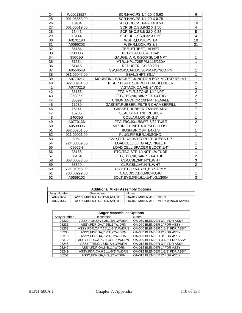
BLN1-600A.1 Chapter 7: Appendix 110 of 138
24 W00013527 SCR,HHC,PS,1/4-20 X 0.63 6
25 001.05853.00 SCR,HHC,PS,1/4-20 X 0.75 1
26 13434 SCR,BHC,SS,1/4-20 X 0.50 10
27 001.00019.00 SCR,BHC,SS,8-32 X 1.50 4
28 13443 SCR,BHC,SS,8-32 X 0.38 5
29 13144 SCR,BHC,SS,8-32 X 0.50 4
30 A0101190 WSHR,LOCK,PS,1/4 18
31 A0069203 WSHR,LOCK,PS,3/8 21
32 35184 TEE, STREET,1/4"NPT 1
33 35060G REGULATOR, AIR 1/4" 1
34 35061G GAUGE, AIR, 0-200PSI, 1/8 NPT 1
35 51354 MTR,1HP,1725RPM,115/230V 1
36 51415 REDUCER,ICS-60 20:1 1
37 A0556548 SW,PROX,CAP,DC,30MM,NO/NC,NPN 1
38 081.00042.00 SEAL,SHFT,SS,1" 1
39 A0770217 MOUNTING BRACKET JUNCTION BOX MOTOR RELAY 1
40 822.00904.00 RISER PLATE SUPPORT OA BLENDER 2
41 A0770218 V,STACK,OA,A/B,24VDC 1
42 35158 FTG,MFLR,STONE,1/4" NPT 2
43 35086K FTG,TBG,90,1/8NPT X 1/4TBG 2
44 35392 UNION,ANCHOR 1/8"NPT FEMALE 1
45 15239 GASKET,RUBBER, FILTER CHAMBERFILL 7
46 15241 GASKET,RUBBER, RWIMB-MINI 7
47 15286 SEAL,SHFT,1"ID,RUBBER 1
48 24008G COLLAR,LOCKING,1" 1
49 A0770136 FTG,TBG,90,1/8MPT-5/32 TUBE 2
50 A0538306 NIP,BR,0.13NPT X 0.75LG,CLOSE 1
51 032.00201.00 BUSH,BR,OSH,1/4X1/8 1
52 021.00001.00 PLUG,PIPE,BR,1/8,SQHD, 1
53 8982 CVR,PLT,OA-060,TOPPLT,DRESS-UP 1
54 724.00839.00 LOADCELL,30KG,AL,SINGLE P 1
55 08605N LOAD CELL SPACER BLOCK 1/4" 1
56 35155 FTG,TBG,STR,1/4NPT-1/4 TUBE 1
57 35154 FTG,TBG,90,1/4NPT-1/4 TUBE 2
58 008.00038.00 CLP,CBL,3/8",NYL,WHT 3
59 53329 CLP,CBL,1/4",NYL,WHT 2
60 721.01058.02 PB,E,STOP,N4,YEL,BOX,40MM 1
61 700.00299.00 CA,QDISC,DC,MICRO,4C 1
62 A0569102 BOLT,EYE,3/8-16,1-1/4"LG,1300# 3
Additional Mixer Assembly Options Assy Number Description Notes
A0771657 ASSY,MIXER,OA-012-6,A/B,HC OA-012 MIXER ASSEMBLY
A0771647 ASSY,MIXER,OA-060-6,A/B,HC OA-060 MIXER ASSEMBLY (Shown Above)
Auger Assemblies Options Assy Number Description Notes
08229 ASSY,FDR,OA,7.25L,3/4",W/DRN OA-060 BLENDER 3/4" FDR ASSY
08231 ASSY,FDR,OA,7.25L,1",W/DRN OA-060 BLENDER 1" FDR ASSY
08233 ASSY,FDR,OA,7.25L,1-5/8",W/DRN OA-060 BLENDER 1-5/8" FDR ASSY
08235 ASSY,FDR,OA,7.25L,2",W/DRN OA-060 BLENDER 2" FDR ASSY
08310 ASSY,FDR,OA,7.75L,3",W/DRN OA-060 BLENDER 3" FDR ASSY
08312 ASSY,FDR,OA,7.75L,3-1/2",W/DRN OA-060 BLENDER 3-1/2" FDR ASSY
08245 ASSY,FDR,OA,6.5L,3/4",W/DRN OA-012 BLENDER 3/4" FDR ASSY
08247 ASSY,FDR,OA,6.5L,1",W/DRN OA-012 BLENDER 1" FDR ASSY
08249 ASSY,FDR,OA,6.5L,1-5/8",W/DRN OA-012 BLENDER 1-5/8" FDR ASSY
08251 ASSY,FDR,OA,6.5L,2",W/DRN OA-012 BLENDER 2" FDR ASSY
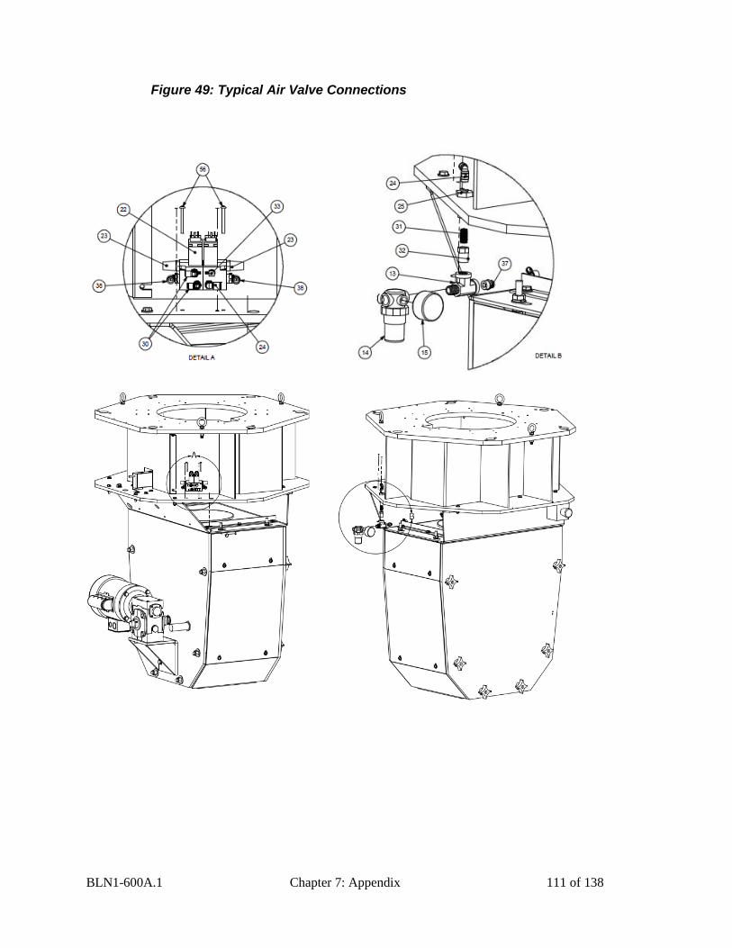
BLN1-600A.1 Chapter 7: Appendix 111 of 138
Figure 49: Typical Air Valve Connections
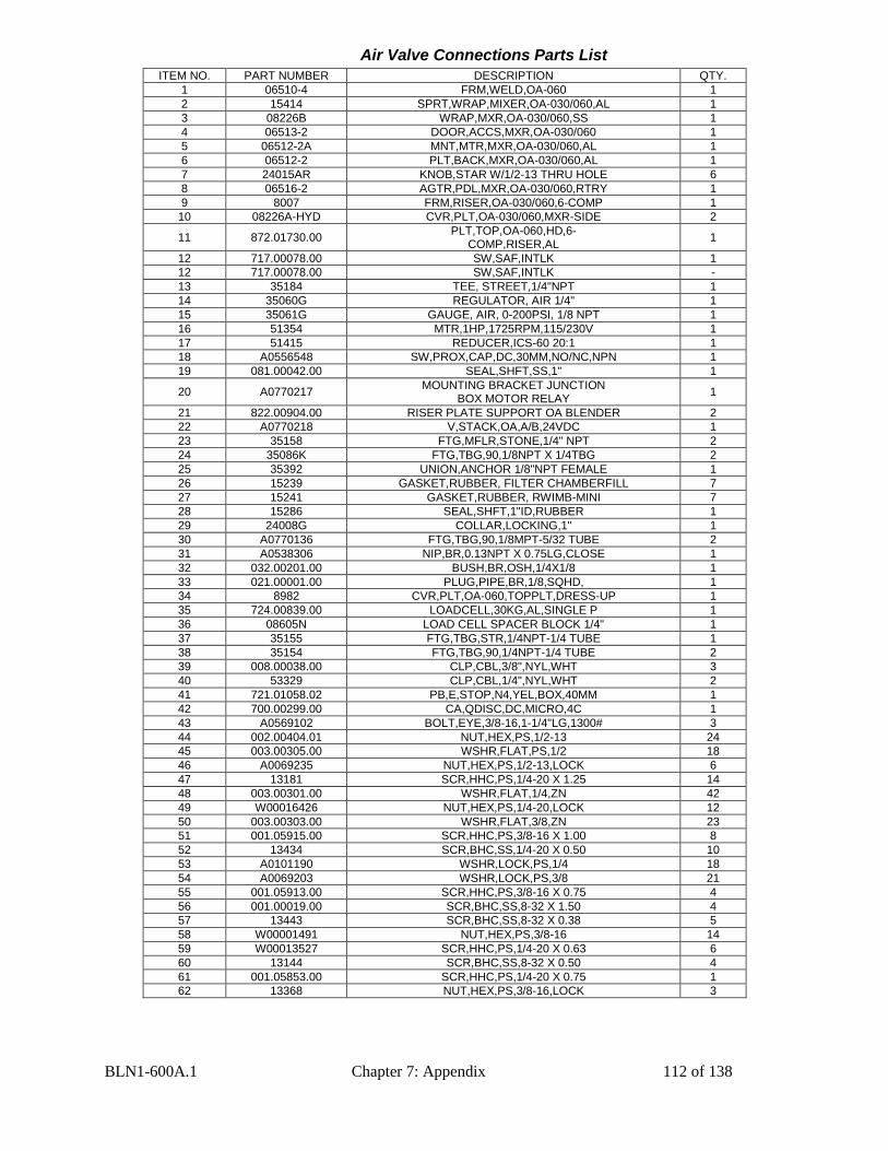
BLN1-600A.1 Chapter 7: Appendix 112 of 138
Air Valve Connections Parts List
ITEM NO. PART NUMBER DESCRIPTION QTY.
1 06510-4 FRM,WELD,OA-060 1
2 15414 SPRT,WRAP,MIXER,OA-030/060,AL 1
3 08226B WRAP,MXR,OA-030/060,SS 1
4 06513-2 DOOR,ACCS,MXR,OA-030/060 1
5 06512-2A MNT,MTR,MXR,OA-030/060,AL 1
6 06512-2 PLT,BACK,MXR,OA-030/060,AL 1
7 24015AR KNOB,STAR W/1/2-13 THRU HOLE 6
8 06516-2 AGTR,PDL,MXR,OA-030/060,RTRY 1
9 8007 FRM,RISER,OA-030/060,6-COMP 1
10 08226A-HYD CVR,PLT,OA-030/060,MXR-SIDE 2
11 872.01730.00 PLT,TOP,OA-060,HD,6-
COMP,RISER,AL 1
12 717.00078.00 SW,SAF,INTLK 1
12 717.00078.00 SW,SAF,INTLK -
13 35184 TEE, STREET,1/4"NPT 1
14 35060G REGULATOR, AIR 1/4" 1
15 35061G GAUGE, AIR, 0-200PSI, 1/8 NPT 1
16 51354 MTR,1HP,1725RPM,115/230V 1
17 51415 REDUCER,ICS-60 20:1 1
18 A0556548 SW,PROX,CAP,DC,30MM,NO/NC,NPN 1
19 081.00042.00 SEAL,SHFT,SS,1" 1
20 A0770217 MOUNTING BRACKET JUNCTION
BOX MOTOR RELAY 1
21 822.00904.00 RISER PLATE SUPPORT OA BLENDER 2
22 A0770218 V,STACK,OA,A/B,24VDC 1
23 35158 FTG,MFLR,STONE,1/4" NPT 2
24 35086K FTG,TBG,90,1/8NPT X 1/4TBG 2
25 35392 UNION,ANCHOR 1/8"NPT FEMALE 1
26 15239 GASKET,RUBBER, FILTER CHAMBERFILL 7
27 15241 GASKET,RUBBER, RWIMB-MINI 7
28 15286 SEAL,SHFT,1"ID,RUBBER 1
29 24008G COLLAR,LOCKING,1" 1
30 A0770136 FTG,TBG,90,1/8MPT-5/32 TUBE 2
31 A0538306 NIP,BR,0.13NPT X 0.75LG,CLOSE 1
32 032.00201.00 BUSH,BR,OSH,1/4X1/8 1
33 021.00001.00 PLUG,PIPE,BR,1/8,SQHD, 1
34 8982 CVR,PLT,OA-060,TOPPLT,DRESS-UP 1
35 724.00839.00 LOADCELL,30KG,AL,SINGLE P 1
36 08605N LOAD CELL SPACER BLOCK 1/4" 1
37 35155 FTG,TBG,STR,1/4NPT-1/4 TUBE 1
38 35154 FTG,TBG,90,1/4NPT-1/4 TUBE 2
39 008.00038.00 CLP,CBL,3/8",NYL,WHT 3
40 53329 CLP,CBL,1/4",NYL,WHT 2
41 721.01058.02 PB,E,STOP,N4,YEL,BOX,40MM 1
42 700.00299.00 CA,QDISC,DC,MICRO,4C 1
43 A0569102 BOLT,EYE,3/8-16,1-1/4"LG,1300# 3
44 002.00404.01 NUT,HEX,PS,1/2-13 24
45 003.00305.00 WSHR,FLAT,PS,1/2 18
46 A0069235 NUT,HEX,PS,1/2-13,LOCK 6
47 13181 SCR,HHC,PS,1/4-20 X 1.25 14
48 003.00301.00 WSHR,FLAT,1/4,ZN 42
49 W00016426 NUT,HEX,PS,1/4-20,LOCK 12
50 003.00303.00 WSHR,FLAT,3/8,ZN 23
51 001.05915.00 SCR,HHC,PS,3/8-16 X 1.00 8
52 13434 SCR,BHC,SS,1/4-20 X 0.50 10
53 A0101190 WSHR,LOCK,PS,1/4 18
54 A0069203 WSHR,LOCK,PS,3/8 21
55 001.05913.00 SCR,HHC,PS,3/8-16 X 0.75 4
56 001.00019.00 SCR,BHC,SS,8-32 X 1.50 4
57 13443 SCR,BHC,SS,8-32 X 0.38 5
58 W00001491 NUT,HEX,PS,3/8-16 14
59 W00013527 SCR,HHC,PS,1/4-20 X 0.63 6
60 13144 SCR,BHC,SS,8-32 X 0.50 4
61 001.05853.00 SCR,HHC,PS,1/4-20 X 0.75 1
62 13368 NUT,HEX,PS,3/8-16,LOCK 3
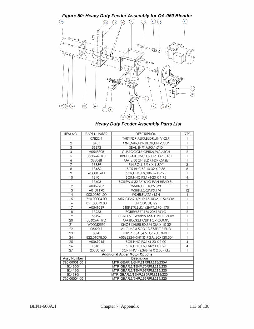
BLN1-600A.1 Chapter 7: Appendix 113 of 138
Figure 50: Heavy Duty Feeder Assembly for OA-060 Blender
Heavy Duty Feeder Assembly Parts List
ITEM NO. PART NUMBER DESCRIPTION QTY.
1 07822-1 THRT,FDR,AUG,BLDR,UNIV,CLP 1
2 8451 MNT,MTR,FDR,BLDR,UNIV,CLP 1
3 55372 SEAL,SHFT,AUG,1.0"ID 1
4 A0548808 CLP,TOGGLE,CPRSN,W/LATCH 2
5 08806A-HYD BRKT,GATE,DSCH,BLDR,FDR,CAST 1
6 08806B GATE,DSCH,BLDR,FDR,CASE 1
7 13389 PIN,ROLL 5/16 X 1-3/4" 3
8 13436 SCR,BHC,SS,10-32 X 0.38 8
9 W00001414 SCR,HHC,PS,3/8-16 X 2.25 1
10 13401 SCR,HHC,PS,1/4-20 X 1.75 4
11 13403 SCREW,6-32 3/16"LG PAN HEAD SL 1
12 A0069203 WSHR,LOCK,PS,3/8 2
13 A0101190 WSHR,LOCK,PS,1/4 12
14 003.00301.00 WSHR,FLAT,1/4,ZN 4
15 720.00004.00 MTR,GEAR,1/6HP,156RPM,115/230V 1
16 051.00012.00 LN,CDCUT,1/2 1
17 A0541039 STRF,STR,BLK,1/2NPT,.170-.470 1
18 13263 SCREW,SET,1/4-20X1/4"LG 2
19 55196 CORD,6FT,W/3PIN MALE PLUG,600V 1
20 08605A-HYD OA BUCKET CLIP FOR COMP. 1
21 W00052550 KNOB,KNURLED,3/4 DIA X 10-32 1
22 08320-1 AUG,MS,3.5OD,13.375FLT,F-END 1
23 8320 FDR,PIPE,AL,4.5ID,7.75L,DRBLL 1
24 822.01078.00 A0566224--SHT,SS,7GA.,60X120,304 1
25 A0069215 SCR,HHC,PS,1/4-20 X 1.00 4
26 13181 SCR,HHC,PS,1/4-20 X 1.25 4
27 120330163 SCR,HHC,PS,3/8-16 X 2.00 - G5 1 Additional Auger Motor Options
Assy Number Description
720.00001.00 MTR,GEAR,1/6HP,21RPM,115/230V
51450G MTR,GEAR,1/15HP,70RPM,115/230
51449G MTR,GEAR,1/15HP,97RPM,115/230
51453G MTR,GEAR,1/15HP,139RPM,115/230
720.00004.00 MTR,GEAR,1/6HP,156RPM,115/230
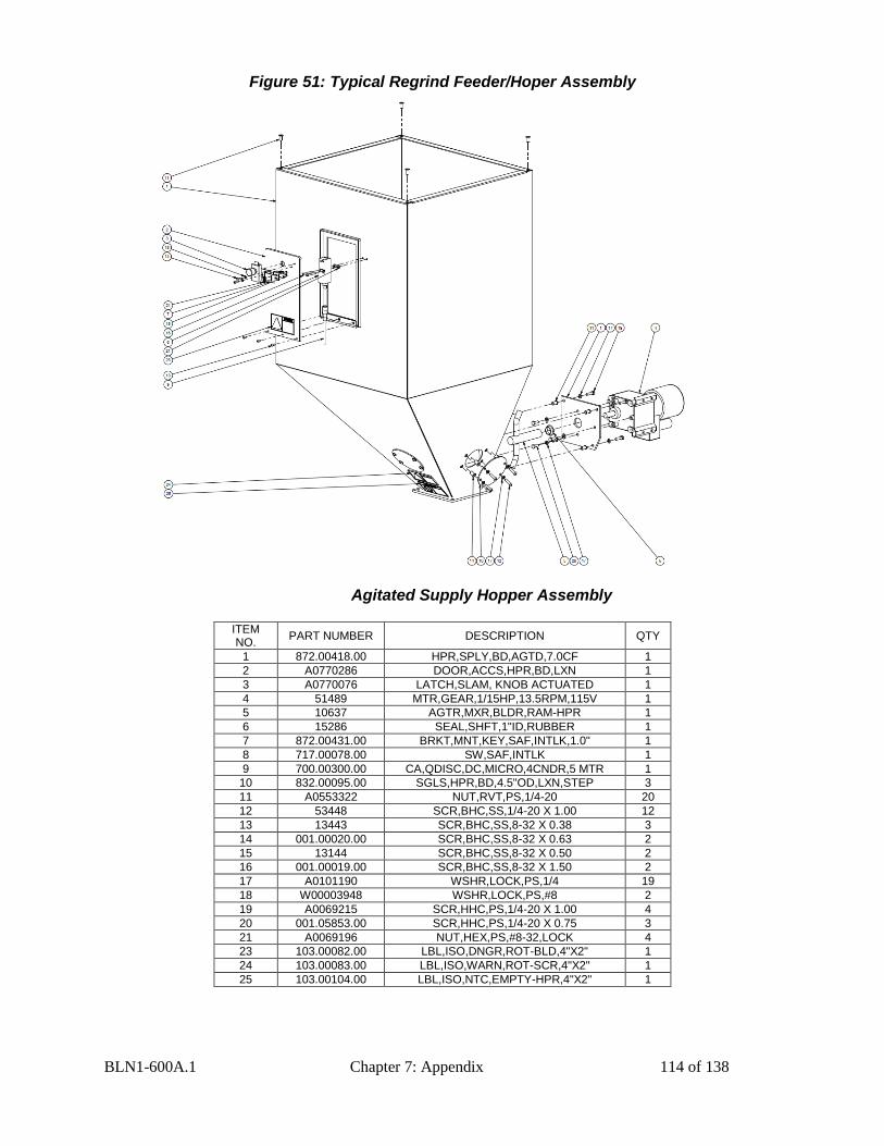
BLN1-600A.1 Chapter 7: Appendix 114 of 138
Figure 51: Typical Regrind Feeder/Hoper Assembly
Agitated Supply Hopper Assembly
ITEM NO.
PART NUMBER DESCRIPTION QTY
1 872.00418.00 HPR,SPLY,BD,AGTD,7.0CF 1
2 A0770286 DOOR,ACCS,HPR,BD,LXN 1
3 A0770076 LATCH,SLAM, KNOB ACTUATED 1
4 51489 MTR,GEAR,1/15HP,13.5RPM,115V 1
5 10637 AGTR,MXR,BLDR,RAM-HPR 1
6 15286 SEAL,SHFT,1"ID,RUBBER 1
7 872.00431.00 BRKT,MNT,KEY,SAF,INTLK,1.0" 1
8 717.00078.00 SW,SAF,INTLK 1
9 700.00300.00 CA,QDISC,DC,MICRO,4CNDR,5 MTR 1
10 832.00095.00 SGLS,HPR,BD,4.5"OD,LXN,STEP 3
11 A0553322 NUT,RVT,PS,1/4-20 20
12 53448 SCR,BHC,SS,1/4-20 X 1.00 12
13 13443 SCR,BHC,SS,8-32 X 0.38 3
14 001.00020.00 SCR,BHC,SS,8-32 X 0.63 2
15 13144 SCR,BHC,SS,8-32 X 0.50 2
16 001.00019.00 SCR,BHC,SS,8-32 X 1.50 2
17 A0101190 WSHR,LOCK,PS,1/4 19
18 W00003948 WSHR,LOCK,PS,#8 2
19 A0069215 SCR,HHC,PS,1/4-20 X 1.00 4
20 001.05853.00 SCR,HHC,PS,1/4-20 X 0.75 3
21 A0069196 NUT,HEX,PS,#8-32,LOCK 4
23 103.00082.00 LBL,ISO,DNGR,ROT-BLD,4"X2" 1
24 103.00083.00 LBL,ISO,WARN,ROT-SCR,4"X2" 1
25 103.00104.00 LBL,ISO,NTC,EMPTY-HPR,4"X2" 1
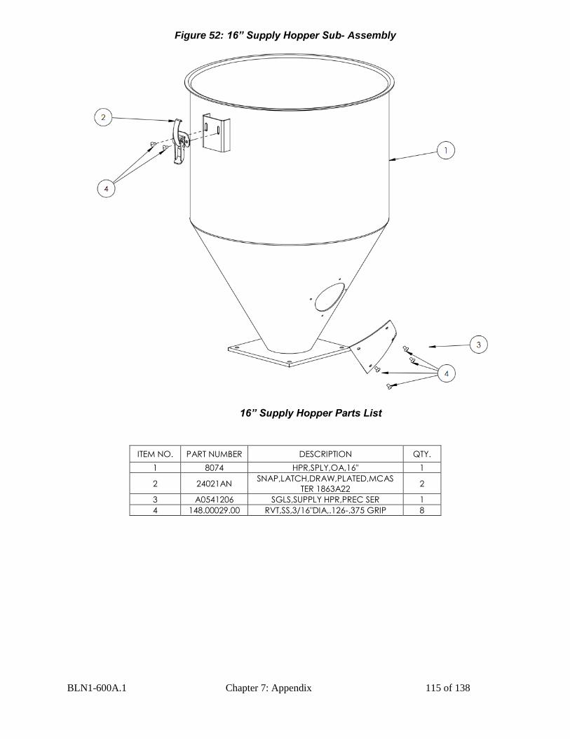
BLN1-600A.1 Chapter 7: Appendix 115 of 138
Figure 52: 16” Supply Hopper Sub- Assembly
16” Supply Hopper Parts List
ITEM NO. PART NUMBER DESCRIPTION QTY.
1 8074 HPR,SPLY,OA,16" 1
2 24021AN SNAP,LATCH,DRAW,PLATED,MCAS
TER 1863A22 2
3 A0541206 SGLS,SUPPLY HPR,PREC SER 1
4 148.00029.00 RVT,SS,3/16"DIA,.126-.375 GRIP 8
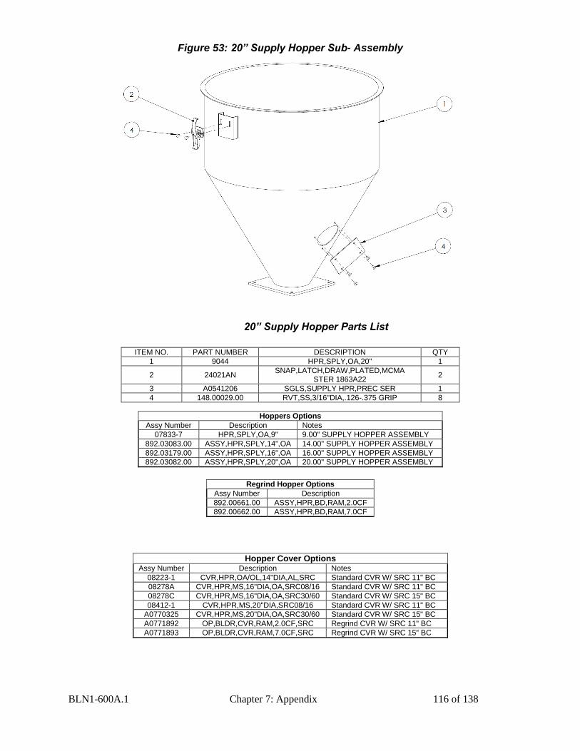
BLN1-600A.1 Chapter 7: Appendix 116 of 138
Figure 53: 20” Supply Hopper Sub- Assembly
20” Supply Hopper Parts List
ITEM NO. PART NUMBER DESCRIPTION QTY
1 9044 HPR,SPLY,OA,20" 1
2 24021AN SNAP,LATCH,DRAW,PLATED,MCMA
STER 1863A22 2
3 A0541206 SGLS,SUPPLY HPR,PREC SER 1
4 148.00029.00 RVT,SS,3/16"DIA,.126-.375 GRIP 8
Hoppers Options
Assy Number Description Notes
07833-7 HPR,SPLY,OA,9" 9.00" SUPPLY HOPPER ASSEMBLY
892.03083.00 ASSY,HPR,SPLY,14",OA 14.00" SUPPLY HOPPER ASSEMBLY
892.03179.00 ASSY,HPR,SPLY,16",OA 16.00" SUPPLY HOPPER ASSEMBLY
892.03082.00 ASSY,HPR,SPLY,20",OA 20.00" SUPPLY HOPPER ASSEMBLY
Regrind Hopper Options
Assy Number Description
892.00661.00 ASSY,HPR,BD,RAM,2.0CF
892.00662.00 ASSY,HPR,BD,RAM,7.0CF
Hopper Cover Options
Assy Number Description Notes
08223-1 CVR,HPR,OA/OL,14"DIA,AL,SRC Standard CVR W/ SRC 11" BC
08278A CVR,HPR,MS,16"DIA,OA,SRC08/16 Standard CVR W/ SRC 11" BC
08278C CVR,HPR,MS,16"DIA,OA,SRC30/60 Standard CVR W/ SRC 15" BC
08412-1 CVR,HPR,MS,20"DIA,SRC08/16 Standard CVR W/ SRC 11" BC
A0770325 CVR,HPR,MS,20"DIA,OA,SRC30/60 Standard CVR W/ SRC 15" BC
A0771892 OP,BLDR,CVR,RAM,2.0CF,SRC Regrind CVR W/ SRC 11" BC
A0771893 OP,BLDR,CVR,RAM,7.0CF,SRC Regrind CVR W/ SRC 15" BC
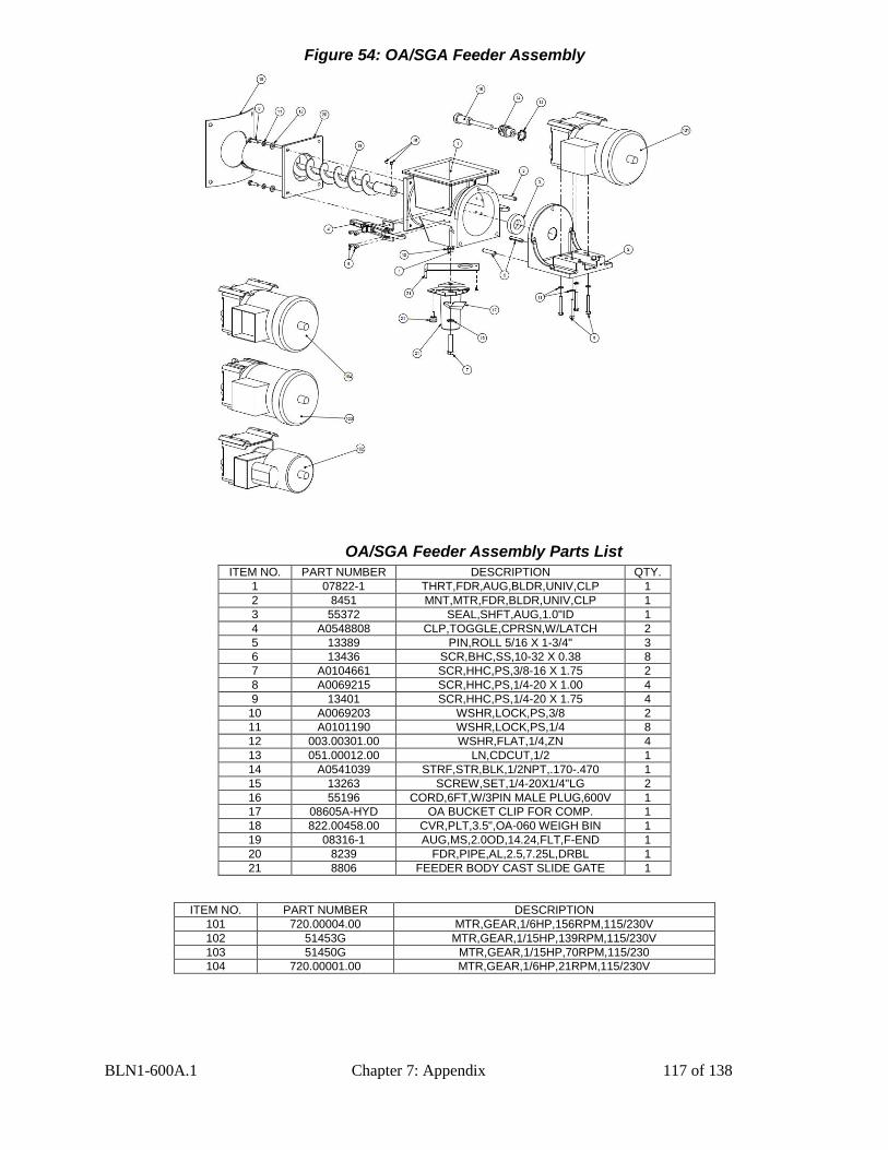
BLN1-600A.1 Chapter 7: Appendix 117 of 138
Figure 54: OA/SGA Feeder Assembly
OA/SGA Feeder Assembly Parts List
ITEM NO. PART NUMBER DESCRIPTION QTY.
1 07822-1 THRT,FDR,AUG,BLDR,UNIV,CLP 1
2 8451 MNT,MTR,FDR,BLDR,UNIV,CLP 1
3 55372 SEAL,SHFT,AUG,1.0"ID 1
4 A0548808 CLP,TOGGLE,CPRSN,W/LATCH 2
5 13389 PIN,ROLL 5/16 X 1-3/4" 3
6 13436 SCR,BHC,SS,10-32 X 0.38 8
7 A0104661 SCR,HHC,PS,3/8-16 X 1.75 2
8 A0069215 SCR,HHC,PS,1/4-20 X 1.00 4
9 13401 SCR,HHC,PS,1/4-20 X 1.75 4
10 A0069203 WSHR,LOCK,PS,3/8 2
11 A0101190 WSHR,LOCK,PS,1/4 8
12 003.00301.00 WSHR,FLAT,1/4,ZN 4
13 051.00012.00 LN,CDCUT,1/2 1
14 A0541039 STRF,STR,BLK,1/2NPT,.170-.470 1
15 13263 SCREW,SET,1/4-20X1/4"LG 2
16 55196 CORD,6FT,W/3PIN MALE PLUG,600V 1
17 08605A-HYD OA BUCKET CLIP FOR COMP. 1
18 822.00458.00 CVR,PLT,3.5",OA-060 WEIGH BIN 1
19 08316-1 AUG,MS,2.0OD,14.24,FLT,F-END 1
20 8239 FDR,PIPE,AL,2.5,7.25L,DRBL 1
21 8806 FEEDER BODY CAST SLIDE GATE 1
ITEM NO. PART NUMBER DESCRIPTION
101 720.00004.00 MTR,GEAR,1/6HP,156RPM,115/230V
102 51453G MTR,GEAR,1/15HP,139RPM,115/230V
103 51450G MTR,GEAR,1/15HP,70RPM,115/230
104 720.00001.00 MTR,GEAR,1/6HP,21RPM,115/230V
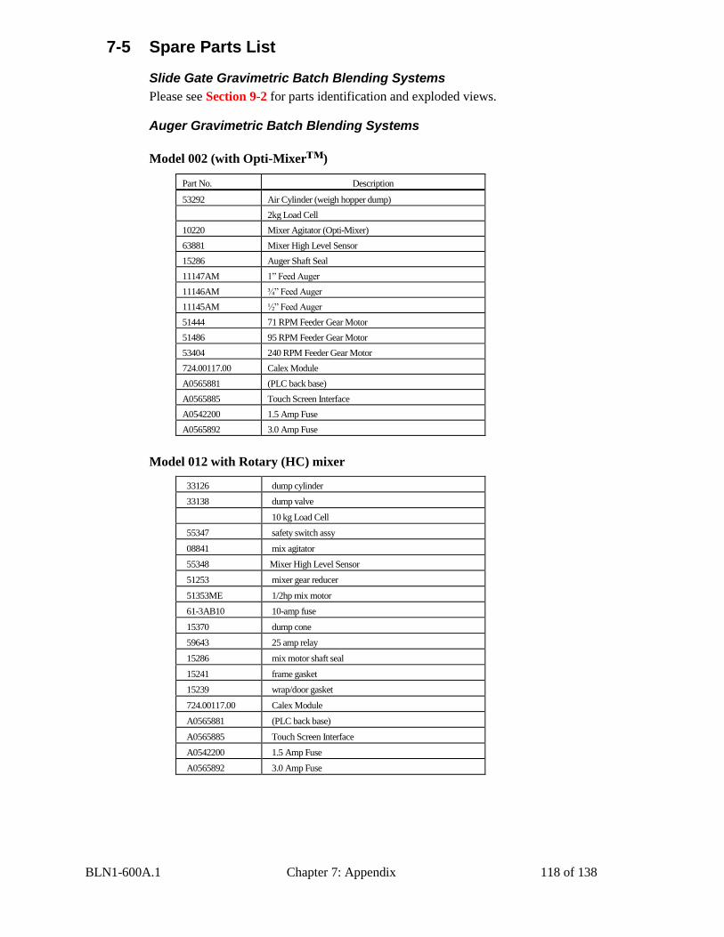
BLN1-600A.1 Chapter 7: Appendix 118 of 138
7-5 Spare Parts List
Slide Gate Gravimetric Batch Blending Systems
Please see Section 9-2 for parts identification and exploded views.
Auger Gravimetric Batch Blending Systems
Model 002 (with Opti-Mixer™)
Part No. Description
53292 Air Cylinder (weigh hopper dump)
2kg Load Cell
10220 Mixer Agitator (Opti-Mixer)
63881 Mixer High Level Sensor
15286 Auger Shaft Seal
11147AM 1” Feed Auger
11146AM ¾” Feed Auger
11145AM ½” Feed Auger
51444 71 RPM Feeder Gear Motor
51486 95 RPM Feeder Gear Motor
53404 240 RPM Feeder Gear Motor
724.00117.00 Calex Module
A0565881 (PLC back base)
A0565885 Touch Screen Interface
A0542200 1.5 Amp Fuse
A0565892 3.0 Amp Fuse
Model 012 with Rotary (HC) mixer
33126 dump cylinder
33138 dump valve
10 kg Load Cell
55347 safety switch assy
08841 mix agitator
55348 Mixer High Level Sensor
51253 mixer gear reducer
51353ME 1/2hp mix motor
61-3AB10 10-amp fuse
15370 dump cone
59643 25 amp relay
15286 mix motor shaft seal
15241 frame gasket
15239 wrap/door gasket
724.00117.00 Calex Module
A0565881 (PLC back base)
A0565885 Touch Screen Interface
A0542200 1.5 Amp Fuse
A0565892 3.0 Amp Fuse
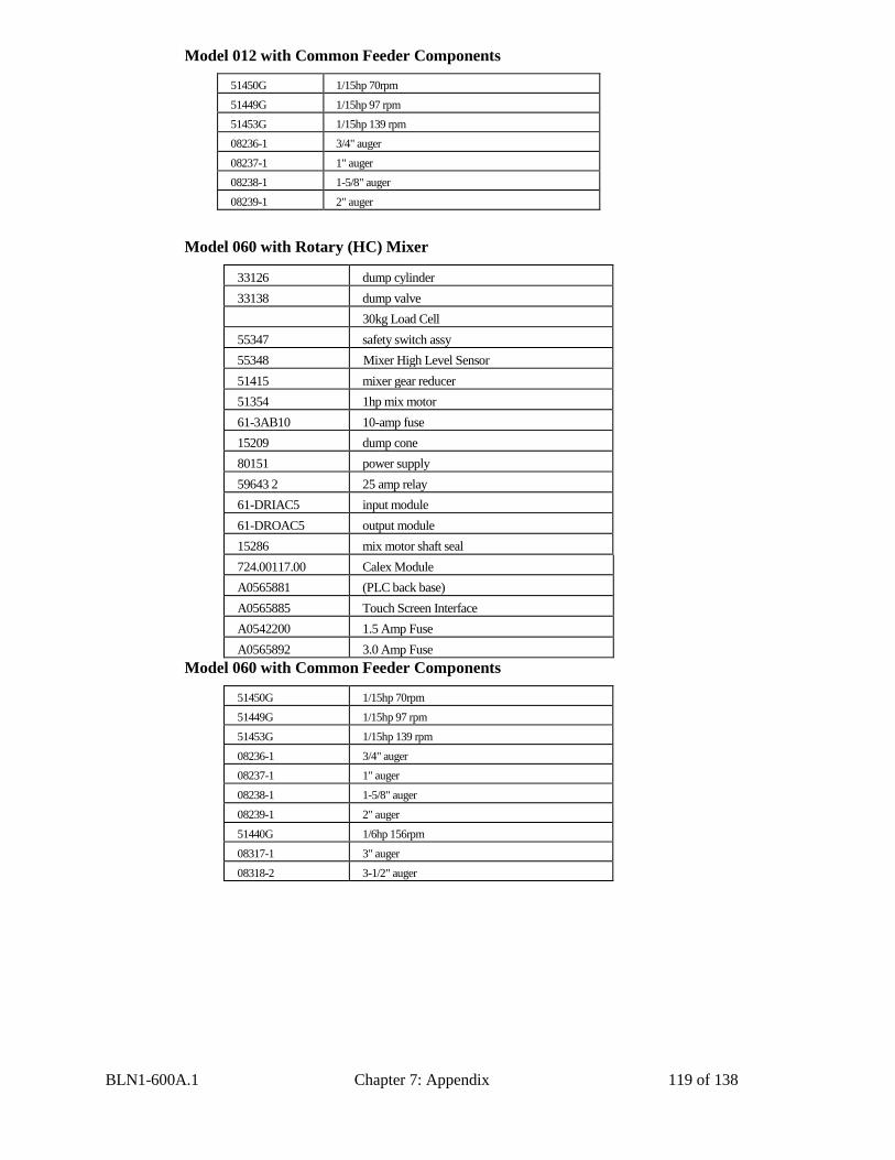
BLN1-600A.1 Chapter 7: Appendix 119 of 138
Model 012 with Common Feeder Components
51450G 1/15hp 70rpm
51449G 1/15hp 97 rpm
51453G 1/15hp 139 rpm
08236-1 3/4" auger
08237-1 1" auger
08238-1 1-5/8" auger
08239-1 2" auger
Model 060 with Rotary (HC) Mixer
33126 dump cylinder
33138 dump valve
30kg Load Cell
55347 safety switch assy
55348 Mixer High Level Sensor
51415 mixer gear reducer
51354 1hp mix motor
61-3AB10 10-amp fuse
15209 dump cone
80151 power supply
59643 2 25 amp relay
61-DRIAC5 input module
61-DROAC5 output module
15286 mix motor shaft seal
724.00117.00 Calex Module
A0565881 (PLC back base)
A0565885 Touch Screen Interface
A0542200 1.5 Amp Fuse
A0565892 3.0 Amp Fuse
Model 060 with Common Feeder Components
51450G 1/15hp 70rpm
51449G 1/15hp 97 rpm
51453G 1/15hp 139 rpm
08236-1 3/4" auger
08237-1 1" auger
08238-1 1-5/8" auger
08239-1 2" auger
51440G 1/6hp 156rpm
08317-1 3" auger
08318-2 3-1/2" auger
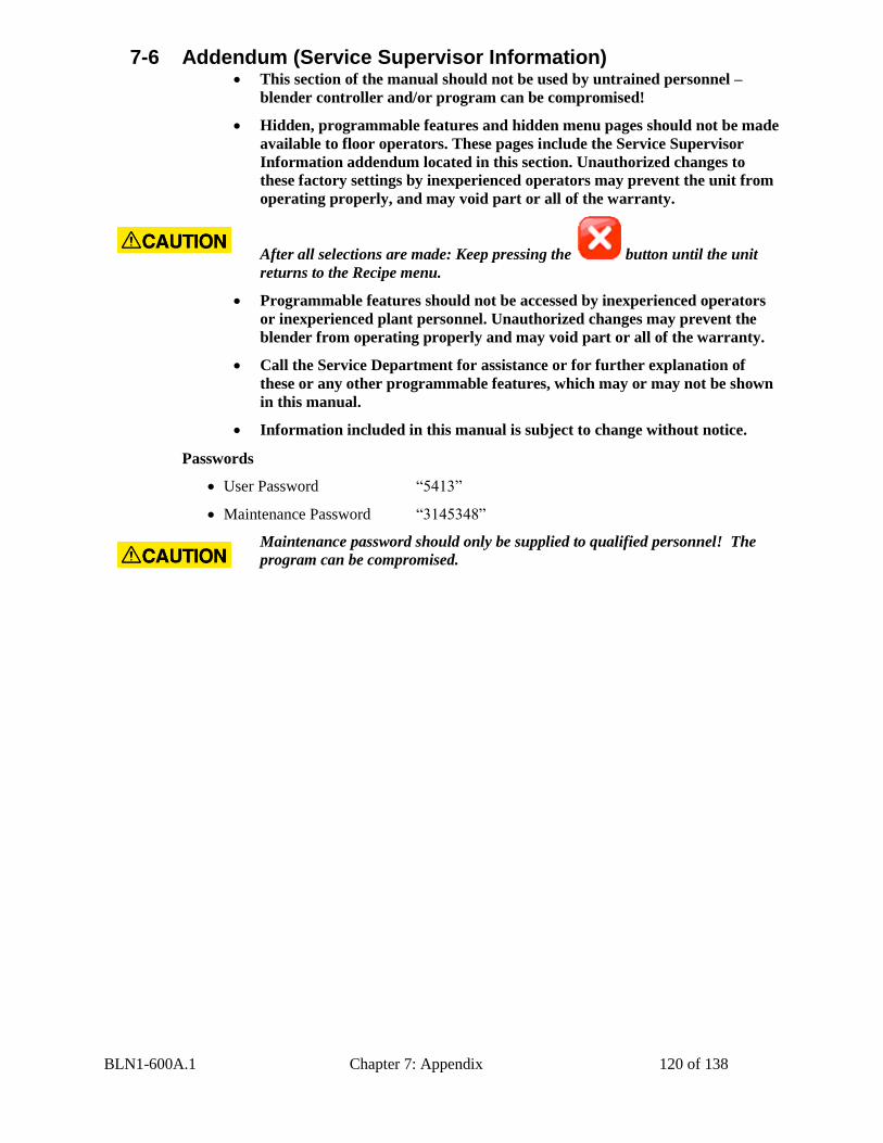
BLN1-600A.1 Chapter 7: Appendix 120 of 138
7-6 Addendum (Service Supervisor Information)
After all selections are made: Keep pressing the button until the unit
returns to the Recipe menu.
Passwords
User Password “5413”
Maintenance Password “3145348”
Maintenance password should only be supplied to qualified personnel! The
program can be compromised.
This section of the manual should not be used by untrained personnel –
blender controller and/or program can be compromised!
Hidden, programmable features and hidden menu pages should not be made
available to floor operators. These pages include the Service Supervisor
Information addendum located in this section. Unauthorized changes to
these factory settings by inexperienced operators may prevent the unit from
operating properly, and may void part or all of the warranty.
Programmable features should not be accessed by inexperienced operators
or inexperienced plant personnel. Unauthorized changes may prevent the
blender from operating properly and may void part or all of the warranty.
Call the Service Department for assistance or for further explanation of
these or any other programmable features, which may or may not be shown
in this manual.
Information included in this manual is subject to change without notice.
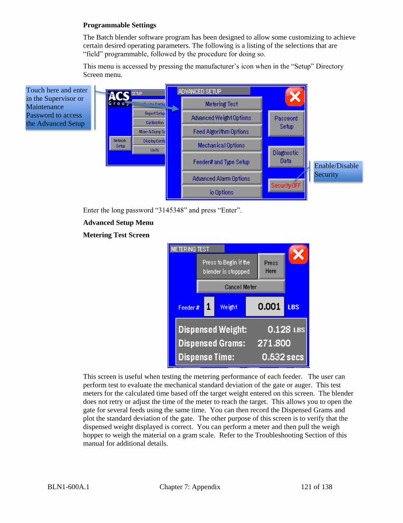
BLN1-600A.1 Chapter 7: Appendix 121 of 138
Programmable Settings
The Batch blender software program has been designed to allow some customizing to achieve
certain desired operating parameters. The following is a listing of the selections that are
“field” programmable, followed by the procedure for doing so.
This menu is accessed by pressing the manufacturer’s icon when in the “Setup” Directory
Screen menu.
Enter the long password “3145348” and press “Enter”.
Advanced Setup Menu
Metering Test Screen
This screen is useful when testing the metering performance of each feeder. The user can
perform test to evaluate the mechanical standard deviation of the gate or auger. This test
meters for the calculated time based off the target weight entered on this screen. The blender
does not retry or adjust the time of the meter to reach the target. This allows you to open the
gate for several feeds using the same time. You can then record the Dispensed Grams and
plot the standard deviation of the gate. The other purpose of this screen is to verify that the
dispensed weight displayed is correct. You can perform a meter and then pull the weigh
hopper to weigh the material on a gram scale. Refer to the Troubleshooting Section of this
manual for additional details.
Touch here and enter
in the Supervisor or
Maintenance
Password to access
the Advanced Setup
Menu
Enable/Disable
Security
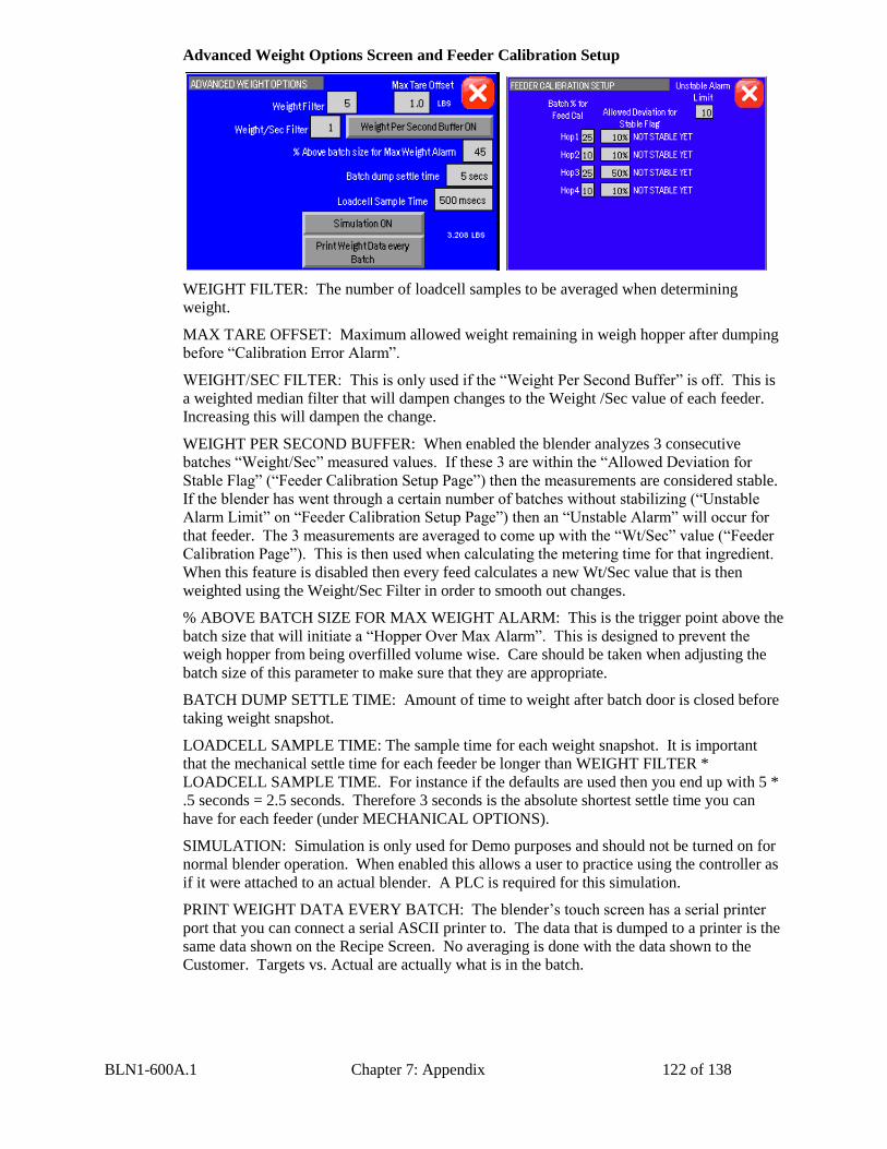
BLN1-600A.1 Chapter 7: Appendix 122 of 138
Advanced Weight Options Screen and Feeder Calibration Setup
WEIGHT FILTER: The number of loadcell samples to be averaged when determining
weight.
MAX TARE OFFSET: Maximum allowed weight remaining in weigh hopper after dumping
before “Calibration Error Alarm”.
WEIGHT/SEC FILTER: This is only used if the “Weight Per Second Buffer” is off. This is
a weighted median filter that will dampen changes to the Weight /Sec value of each feeder.
Increasing this will dampen the change.
WEIGHT PER SECOND BUFFER: When enabled the blender analyzes 3 consecutive
batches “Weight/Sec” measured values. If these 3 are within the “Allowed Deviation for
Stable Flag” (“Feeder Calibration Setup Page”) then the measurements are considered stable.
If the blender has went through a certain number of batches without stabilizing (“Unstable
Alarm Limit” on “Feeder Calibration Setup Page”) then an “Unstable Alarm” will occur for
that feeder. The 3 measurements are averaged to come up with the “Wt/Sec” value (“Feeder
Calibration Page”). This is then used when calculating the metering time for that ingredient.
When this feature is disabled then every feed calculates a new Wt/Sec value that is then
weighted using the Weight/Sec Filter in order to smooth out changes.
% ABOVE BATCH SIZE FOR MAX WEIGHT ALARM: This is the trigger point above the
batch size that will initiate a “Hopper Over Max Alarm”. This is designed to prevent the
weigh hopper from being overfilled volume wise. Care should be taken when adjusting the
batch size of this parameter to make sure that they are appropriate.
BATCH DUMP SETTLE TIME: Amount of time to weight after batch door is closed before
taking weight snapshot.
LOADCELL SAMPLE TIME: The sample time for each weight snapshot. It is important
that the mechanical settle time for each feeder be longer than WEIGHT FILTER *
LOADCELL SAMPLE TIME. For instance if the defaults are used then you end up with 5 *
.5 seconds = 2.5 seconds. Therefore 3 seconds is the absolute shortest settle time you can
have for each feeder (under MECHANICAL OPTIONS).
SIMULATION: Simulation is only used for Demo purposes and should not be turned on for
normal blender operation. When enabled this allows a user to practice using the controller as
if it were attached to an actual blender. A PLC is required for this simulation.
PRINT WEIGHT DATA EVERY BATCH: The blender’s touch screen has a serial printer
port that you can connect a serial ASCII printer to. The data that is dumped to a printer is the
same data shown on the Recipe Screen. No averaging is done with the data shown to the
Customer. Targets vs. Actual are actually what is in the batch.
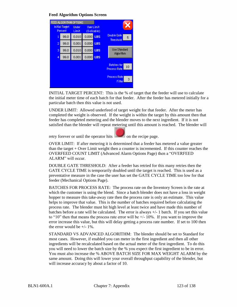
BLN1-600A.1 Chapter 7: Appendix 123 of 138
Feed Algorithm Options Screen
INITIAL TARGET PERCENT: This is the % of target that the feeder will use to calculate
the initial meter time of each batch for that feeder. After the feeder has metered initially for a
particular batch then this value is not used.
UNDER LIMIT: Allowed underfeed of target weight for that feeder. After the meter has
completed the weight is observed. If the weight is within the target by this amount then that
feeder has completed metering and the blender moves to the next ingredient. If it is not
satisfied than the blender will repeat metering until this amount is reached. The blender will
retry forever or until the operator hits on the recipe page.
OVER LIMIT: If after metering it is determined that a feeder has metered a value greater
than the target + Over Limit weight then a counter is incremented. If this counter reaches the
OVERFEED COUNT LIMIT (Advanced Alarm Options Page) then a “OVERFEED
ALARM” will occur.
DOUBLE GATE THRESHOLD: After a feeder has retried for this many retries then the
GATE CYCLE TIME is temporarily doubled until the target is reached. This is used as a
preventative measure in the case the user has set the GATE CYCLE TIME too low for that
feeder (Mechanical Options Page).
BATCHES FOR PROCESS RATE: The process rate on the Inventory Screen is the rate at
which the customer is using the blend. Since a batch blender does not have a loss in weight
hopper to measure this take-away rate then the process rate is only an estimate. This value
helps to improve that value. This is the number of batches required before calculating the
process rate. The blender must hit high level at least twice and have made this number of
batches before a rate will be calculated. The error is always +/- 1 batch. If you set this value
to “10” then that means the process rate error will be +/- 10%. If you want to improve the
error increase this value, but this will delay getting a process rate number. If set to 100 then
the error would be +/- 1%.
STANDARD VS ADVANCED ALGORITHM: The blender should be set to Standard for
most cases. However, if enabled you can meter in the first ingredient and then all other
ingredients will be recalculated based on the actual meter of the first ingredient. To do this
you will need to lower the batch size by the % you expect the first ingredient to be in error.
You must also increase the % ABOVE BATCH SIZE FOR MAX WEIGHT ALARM by the
same amount. Doing this will lower your overall throughput capability of the blender, but
will increase accuracy by about a factor of 10.
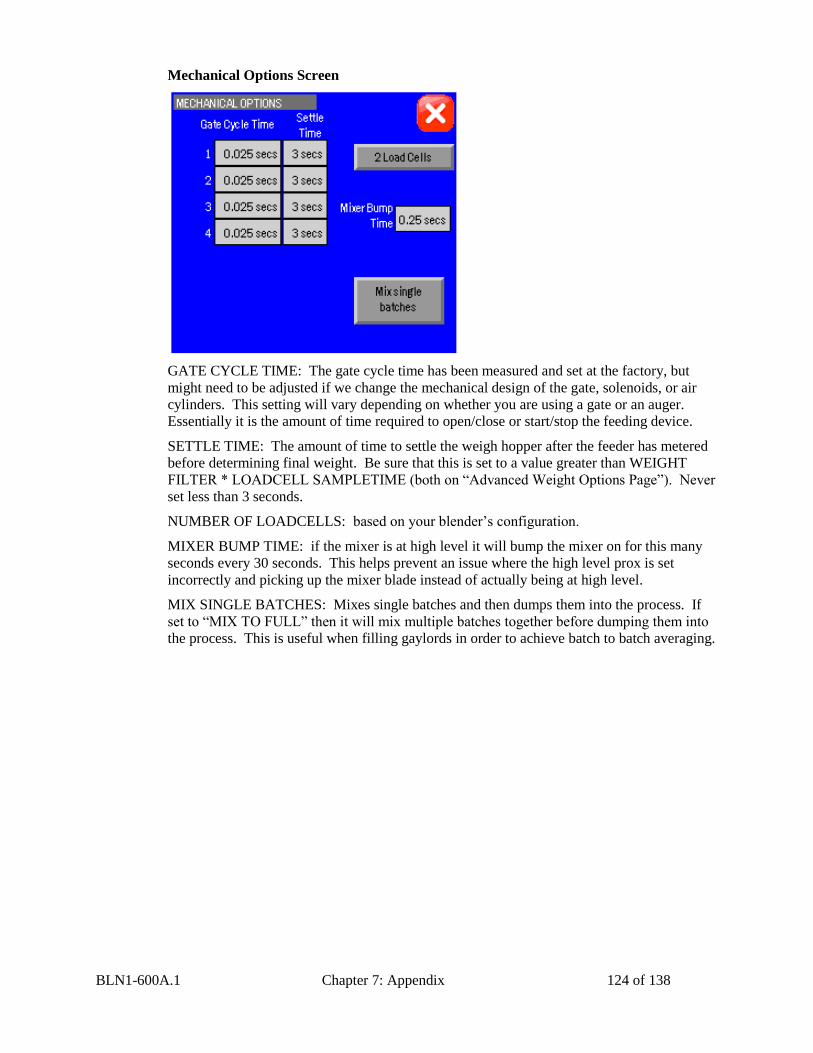
BLN1-600A.1 Chapter 7: Appendix 124 of 138
Mechanical Options Screen
GATE CYCLE TIME: The gate cycle time has been measured and set at the factory, but
might need to be adjusted if we change the mechanical design of the gate, solenoids, or air
cylinders. This setting will vary depending on whether you are using a gate or an auger.
Essentially it is the amount of time required to open/close or start/stop the feeding device.
SETTLE TIME: The amount of time to settle the weigh hopper after the feeder has metered
before determining final weight. Be sure that this is set to a value greater than WEIGHT
FILTER * LOADCELL SAMPLETIME (both on “Advanced Weight Options Page”). Never
set less than 3 seconds.
NUMBER OF LOADCELLS: based on your blender’s configuration.
MIXER BUMP TIME: if the mixer is at high level it will bump the mixer on for this many
seconds every 30 seconds. This helps prevent an issue where the high level prox is set
incorrectly and picking up the mixer blade instead of actually being at high level.
MIX SINGLE BATCHES: Mixes single batches and then dumps them into the process. If
set to “MIX TO FULL” then it will mix multiple batches together before dumping them into
the process. This is useful when filling gaylords in order to achieve batch to batch averaging.
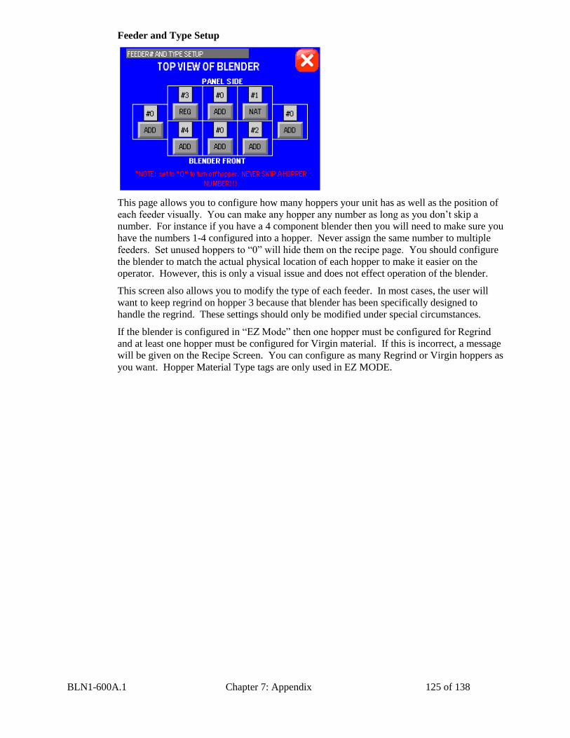
BLN1-600A.1 Chapter 7: Appendix 125 of 138
Feeder and Type Setup
This page allows you to configure how many hoppers your unit has as well as the position of
each feeder visually. You can make any hopper any number as long as you don’t skip a
number. For instance if you have a 4 component blender then you will need to make sure you
have the numbers 1-4 configured into a hopper. Never assign the same number to multiple
feeders. Set unused hoppers to “0” will hide them on the recipe page. You should configure
the blender to match the actual physical location of each hopper to make it easier on the
operator. However, this is only a visual issue and does not effect operation of the blender.
This screen also allows you to modify the type of each feeder. In most cases, the user will
want to keep regrind on hopper 3 because that blender has been specifically designed to
handle the regrind. These settings should only be modified under special circumstances.
If the blender is configured in “EZ Mode” then one hopper must be configured for Regrind
and at least one hopper must be configured for Virgin material. If this is incorrect, a message
will be given on the Recipe Screen. You can configure as many Regrind or Virgin hoppers as
you want. Hopper Material Type tags are only used in EZ MODE.
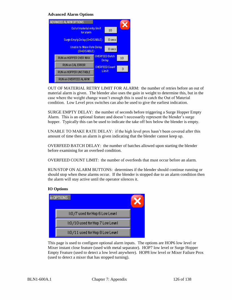
BLN1-600A.1 Chapter 7: Appendix 126 of 138
Advanced Alarm Options
OUT OF MATERIAL RETRY LIMIT FOR ALARM: the number of retries before an out of
material alarm is given. The blender also uses the gain in weight to determine this, but in the
case where the weight change wasn’t enough this is used to catch the Out of Material
condition. Low Level prox switches can also be used to give the earliest indication.
SURGE EMPTY DELAY: the number of seconds before triggering a Surge Hopper Empty
Alarm. This is an optional feature and doesn’t necessarily represent the blender’s surge
hopper. Typically this can be used to indicate the take off box below the blender is empty.
UNABLE TO MAKE RATE DELAY: if the high level prox hasn’t been covered after this
amount of time then an alarm is given indicating that the blender cannot keep up.
OVERFEED BATCH DELAY: the number of batches allowed upon starting the blender
before examining for an overfeed condition.
OVERFEED COUNT LIMIT: the number of overfeeds that must occur before an alarm.
RUN/STOP ON ALARM BUTTONS: determines if the blender should continue running or
should stop when these alarms occur. If the blender is stopped due to an alarm condition then
the alarm will stay active until the operator silences it.
IO Options
This page is used to configure optional alarm inputs. The options are HOP6 low level or
Mixer instant close feature (used with metal separator). HOP7 low level or Surge Hopper
Empty Feature (used to detect a low level anywhere). HOP8 low level or Mixer Failure Prox
(used to detect a mixer that has stopped turning).
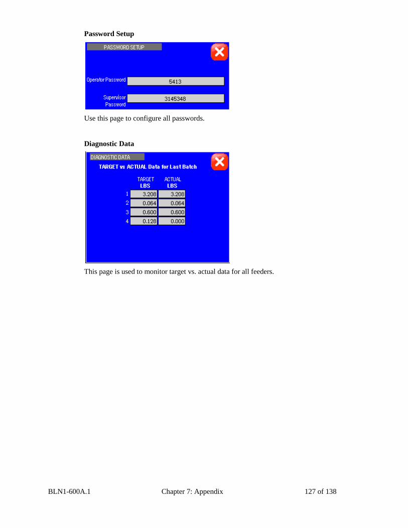
BLN1-600A.1 Chapter 7: Appendix 127 of 138
Password Setup
Use this page to configure all passwords.
Diagnostic Data
This page is used to monitor target vs. actual data for all feeders.
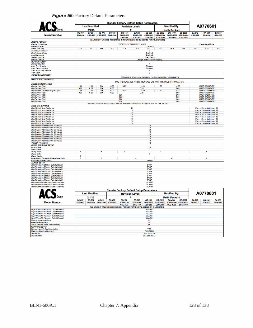
BLN1-600A.1 Chapter 7: Appendix 128 of 138
Figure 55: Factory Default Parameters
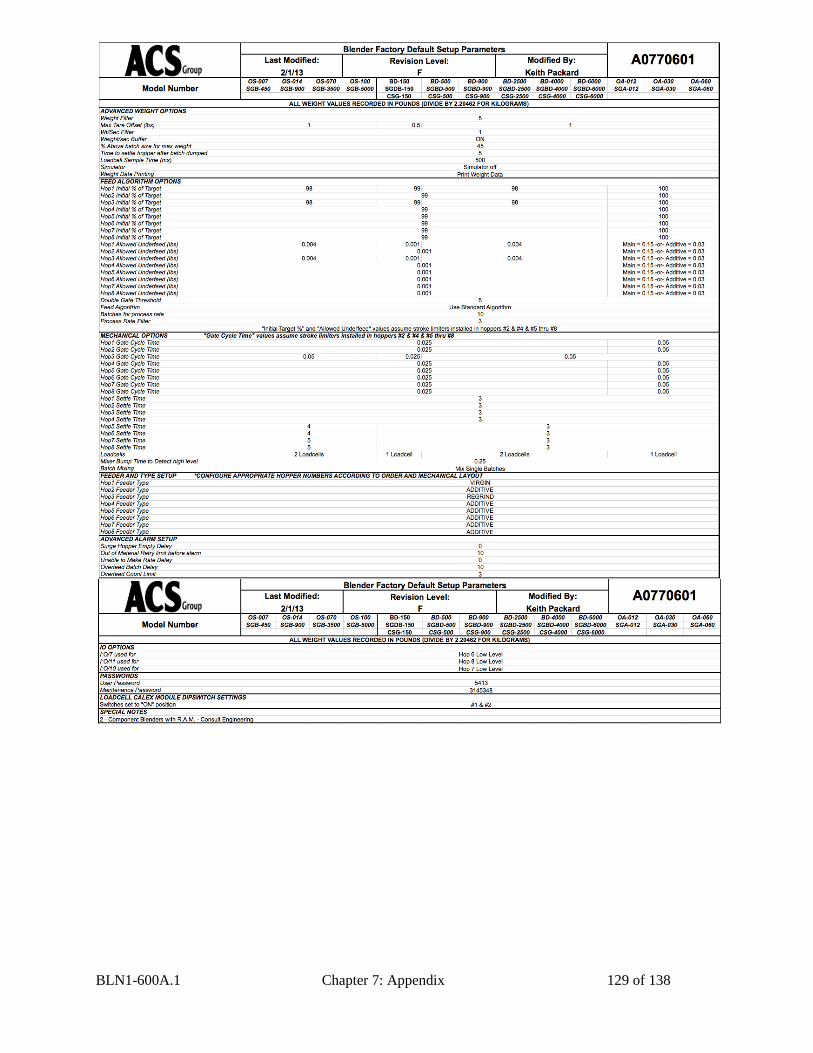
BLN1-600A.1 Chapter 7: Appendix 129 of 138
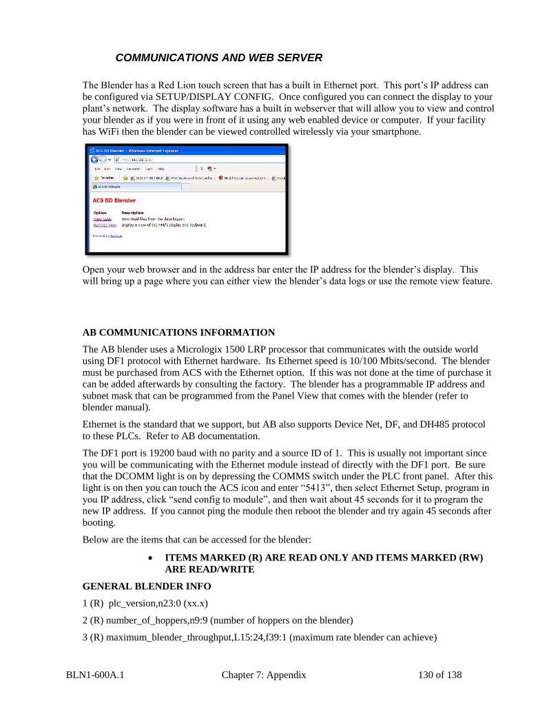
BLN1-600A.1 Chapter 7: Appendix 130 of 138
COMMUNICATIONS AND WEB SERVER
The Blender has a Red Lion touch screen that has a built in Ethernet port. This port’s IP address can
be configured via SETUP/DISPLAY CONFIG. Once configured you can connect the display to your
plant’s network. The display software has a built in webserver that will allow you to view and control
your blender as if you were in front of it using any web enabled device or computer. If your facility
has WiFi then the blender can be viewed controlled wirelessly via your smartphone.
Open your web browser and in the address bar enter the IP address for the blender’s display. This
will bring up a page where you can either view the blender’s data logs or use the remote view feature.
AB COMMUNICATIONS INFORMATION
The AB blender uses a Micrologix 1500 LRP processor that communicates with the outside world
using DF1 protocol with Ethernet hardware. Its Ethernet speed is 10/100 Mbits/second. The blender
must be purchased from ACS with the Ethernet option. If this was not done at the time of purchase it
can be added afterwards by consulting the factory. The blender has a programmable IP address and
subnet mask that can be programmed from the Panel View that comes with the blender (refer to
blender manual).
Ethernet is the standard that we support, but AB also supports Device Net, DF, and DH485 protocol
to these PLCs. Refer to AB documentation.
The DF1 port is 19200 baud with no parity and a source ID of 1. This is usually not important since
you will be communicating with the Ethernet module instead of directly with the DF1 port. Be sure
that the DCOMM light is on by depressing the COMMS switch under the PLC front panel. After this
light is on then you can touch the ACS icon and enter “5413”, then select Ethernet Setup, program in
you IP address, click “send config to module”, and then wait about 45 seconds for it to program the
new IP address. If you cannot ping the module then reboot the blender and try again 45 seconds after
booting.
Below are the items that can be accessed for the blender:
GENERAL BLENDER INFO
1 (R) plc_version,n23:0 (xx.x)
2 (R) number_of_hoppers,n9:9 (number of hoppers on the blender)
3 (R) maximum_blender_throughput,L15:24,f39:1 (maximum rate blender can achieve)
ITEMS MARKED (R) ARE READ ONLY AND ITEMS MARKED (RW)
ARE READ/WRITE
BLN1-600A.1 Chapter 7: Appendix 131 of 138
4 (R) average_batch_time, n16:3 (average amount of time it takes to finish the batch)
5 (R) average_process_rate,L30:30,f39:2 (average rate at which the process is consuming blended
material)
BLENDER STARTING AND STOPPING
1 (R) blender_started,b3:0/0
2 (RW) blender_start_request,b3:0/11 (toggle this to start or stop the blender, blender will switch it’s
current status, you must also reset this bit after completion)
3 (RW) abort_batch_request,b3:0/8 (toggle this to immediately stop the blender even if the batch is
incomplete, you must also reset this bit after completion)
BLENDER ALARMS
1 (R) alarm_number,n11:74 (see below for description)
2 (R) hop1_out_of_material,b28:0/0
3 (R) hop2_out_of_material,b28:0/1
4 (R) hop3_out_of_material,b28:0/2
5 (R) hop4_out_of_material,b28:0/3
6 (R) hop5_out_of_material,b28:0/4
7 (R) hop6_out_of_material,b28:0/5
8 (R) hop7_out_of_material,b28:0/6
9 (R) hop8_out_of_material,b28:0/7
10 (R) hopper_over_max_alarm,b28:0/9
11 (R) empty_weight_exceeded,b28:0/10
12 (R) inventory_cleared,b28:0/11 (use this bit to record when an operator cleared the inventory at the blender)
13 (R) power_interruption,b28:0/15 (this alarm engages when the PLC loses power during a batch)
14 (R) hop1_low_level,b29:2/0 (this alarm is only available if the hoppers have low level prox switches)
15 (R) hop2_low_level,b29:2/1 (this alarm is only available if the hoppers have low level prox switches)
16 (R) hop3_low_level,b29:2/2 (this alarm is only available if the hoppers have low level prox switches)
17 (R) hop4_low_level,b29:2/3 (this alarm is only available if the hoppers have low level prox switches)
18 (R) hop5_low_level,b29:2/4 (this alarm is only available if the hoppers have low level prox switches)
19 (R) hop6_low_level,b29:2/5 (this alarm is only available if the hoppers have low level prox switches)
20 (R) hop7_low_level,b29:2/6 (this alarm is only available if the hoppers have low level prox switches)
21 (R) hop8_low_level,b29:2/7 (this alarm is only available if the hoppers have low level prox switches)
22 (R) plc_battery_low,s:5/11
23 (R) plc_memory_module_loaded,s:5/8 (this alarm only happens while upgrading the blender’s software)
BLN1-600A.1 Chapter 7: Appendix 132 of 138
INVENTORY INFO
1 (RW) clear_inventory,b3:0/3 (toggle this to clear all inventory, you must also reset this bit after
completion)
2 (RW) batch_counter,L30:31,f39:37 (number of batches made)
3 (R) hop1_inventory,L30:0 (this is the whole portion of the inventory) , f39:3 (entire number)
4 (R) hop2_inventory,L30:1 (this is the whole portion of the inventory) , f39:4 (entire number)
5 (R) hop3_inventory,L30:2 (this is the whole portion of the inventory) , f39:5 (entire number)
6 (R) hop4_inventory,L30:3 (this is the whole portion of the inventory) , f39:6 (entire number)
7 (R) hop5_inventory,L30:4 (this is the whole portion of the inventory) , f39:7 (entire number)
8 (R) hop6_inventory,L30:5 (this is the whole portion of the inventory) , f39:8 (entire number)
9 (R) hop7_inventory,L30:6 (this is the whole portion of the inventory) , f39:9 (entire number)
10 (R) hop8_inventory,L30:7 (this is the whole portion of the inventory) , f39:10 (entire number)
11 (R) batch_inventory,L30:35 (this is the whole portion of the inventory) , f39:11 (entire number)
12(R) hop1_fractional_inventory,L30:16 (this is the fractional part of the inventory .xxx)
13 (R) hop2_fractional_inventory,L30:17 (this is the fractional part of the inventory .xxx)
14 (R) hop3_fractional_inventory,L30:18 (this is the fractional part of the inventory .xxx)
15 (R) hop4_fractional_inventory,L30:19 (this is the fractional part of the inventory .xxx)
16 (R) hop5_fractional_inventory,L30:20 (this is the fractional part of the inventory .xxx)
17 (R) hop6_fractional_inventory,L30:21 (this is the fractional part of the inventory .xxx)
18 (R) hop7_fractional_inventory,L30:22 (this is the fractional part of the inventory .xxx)
19 (R) hop8_fractional_inventory,L30:23 (this is the fractional part of the inventory .xxx)
20 (R) batch_inventory_decimal_part,L30:39 (this is the fractional part of the inventory .xxx)
BLN1-600A.1 Chapter 7: Appendix 133 of 138
RECIPE INFO (THIS IS WHERE YOU RIGHT THE NEW RECIPE TO)
1 (RW) temp_recipe_entry_mode,n9:11 (0=percentage mode, 1=parts mode, 2=EZ mode)
2 (R) temp_batch_size_recipe_value,L21:53 (xxx.x lbs or kgs)
3 (RW) pv1_hop1_temp_recipe_value,L20:0 (xxx.xx, write your new recipe here)
4 (RW) pv1_hop2_temp_recipe_value,L20:1 (xxx.xx, write your new recipe here)
5 (RW) pv1_hop3_temp_recipe_value,L20:2 (xxx.xx, write your new recipe here)
6 (RW) pv1_hop4_temp_recipe_value,L20:3 (xxx.xx, write your new recipe here)
7 (RW) pv1_hop5_temp_recipe_value,L20:4 (xxx.xx, write your new recipe here)
8 (RW) pv1_hop6_temp_recipe_value,L20:5 (xxx.xx, write your new recipe here)
9 (RW) pv1_hop7_temp_recipe_value,L20:6 (xxx.xx, write your new recipe here)
10 (RW) pv1_hop8_temp_recipe_value,L20:7 (xxx.xx, write your new recipe here)
11 (R) pv1_recipe_error_message,n9:2 (1=total not 100%, 2=feeder type error, 3=entry over 100%)
12 (R) pv1_accept_recipe_enabled,b3:0/4 (this bit goes high if a new recipe is valid)
13 (RW) pv1_accept_recipe_requested,b3:0/6 (toggle this bit to accept a valid recipe, you must also
reset this bit after completion)
CURRENT RECIPE INFO (THIS IS THE RECIPE THAT IS CURRENTLY BEING MADE)
1 (R) current_recipe_entry_mode,n9:1 (0=percentage mode, 1=parts mode, 2=EZ mode)
2 (R) current_batch_size_recipe_value,L21:20 (xxx.x lbs or kgs), f39:36
3 (R) current_hop1_recipe_value,L21:11 (xxx.xx, recipe value for running recipe), f39:12
4 (R) current_hop2_recipe_value,L21:12 (xxx.xx, recipe value for running recipe) , f39:13
5 (R) current_hop3_recipe_value,L21:13 (xxx.xx, recipe value for running recipe) , f39:14
6 (R) current_hop4_recipe_value,L21:14 (xxx.xx, recipe value for running recipe) , f39:15
7 (R) current_hop5_recipe_value,L21:15 (xxx.xx, recipe value for running recipe) , f39:16
8 (R) current_hop6_recipe_value,L21:16 (xxx.xx, recipe value for running recipe) , f39:17
9 (R) current_hop7_recipe_value,L21:17 (xxx.xx, recipe value for running recipe) , f39:18
10 (R) current_hop8_recipe_value,L21:18 (xxx.xx, recipe value for running recipe) , f39:19
HIDDEN RECIPE INFO (THIS IS THE RAW RECIPE THAT WILL BE LOADED AT NEXT
BATCH)
1 (R) recipe_entry_mode,n9:0 (0=percentage mode, 1=parts mode, 2=EZ mode)
2 (R) batch_size_recipe_value,L21:9 (xxx.x lbs or kgs)
3 (R) hop1_recipe_value,L21:0 (xxx.xx, recipe value for running recipe)
4 (R) hop2_recipe_value,L21:1 (xxx.xx, recipe value for running recipe)
5 (R) hop3_recipe_value,L21:2 (xxx.xx, recipe value for running recipe)
6 (R) hop4_recipe_value,L21:3 (xxx.xx, recipe value for running recipe)
7 (R) hop5_recipe_value,L21:4 (xxx.xx, recipe value for running recipe)
8 (R) hop6_recipe_value,L21:5 (xxx.xx, recipe value for running recipe)
9 (R) hop7_recipe_value,L21:6 (xxx.xx, recipe value for running recipe)
BLN1-600A.1 Chapter 7: Appendix 134 of 138
10 (R) hop8_recipe_value,L21:7 (xxx.xx, recipe value for running recipe)
11 (R) recipe_target_total,L21:8 (xxx.xx, the is the total of hop1-hop8 from above, you must manually
add this if you chose to skip the blenders error checking, you must also ensure that you are in the
correct recipe_entry_mode! SEE BELOW FOR DETAILS)
TARGETS VS. ACTUAL WEIGHT INFO
1 (R) print_data_now,b3:1/11 (read this tag and when it goes high record the actual weights)
2 (R) hop1_displayed_target_weight,L18:0 (target meter weight for batch, xxx.xxx) , f39:20
3 (R) hop2_displayed_target_weight,L18:1 (target meter weight for batch, xxx.xxx) , f39:21
4 (R) hop3_displayed_target_weight,L18:2 (target meter weight for batch, xxx.xxx) , f39:22
5 (R) hop4_displayed_target_weight,L18:3 (target meter weight for batch, xxx.xxx) , f39:23
6 (R) hop5_displayed_target_weight,L18:4 (target meter weight for batch, xxx.xxx) , f39:24
7 (R) hop6_displayed_target_weight,L18:5 (target meter weight for batch, xxx.xxx) , f39:25
8 (R) hop7_displayed_target_weight,L18:6 (target meter weight for batch, xxx.xxx) , f39:26
9 (R) hop8_displayed_target_weight,L18:7 (target meter weight for batch, xxx.xxx) , f39:27
10 (R) hop1_displayed_actual_weight,L19:0 (actual metered weight in batch, xxx.xxx) , f39:28
11 (R) hop2_displayed_actual_weight,L19:1 (actual metered weight in batch, xxx.xxx) , f39:29
12 (R) hop3_displayed_actual_weight,L19:2 (actual metered weight in batch, xxx.xxx) , f39:30
13 (R) hop4_displayed_actual_weight,L19:3 (actual metered weight in batch, xxx.xxx) , f39:31
14 (R) hop5_displayed_actual_weight,L19:4 (actual metered weight in batch, xxx.xxx) , f39:32
15 (R) hop6_displayed_actual_weight,L19:5 (actual metered weight in batch, xxx.xxx) , f39:33
16 (R) hop7_displayed_actual_weight,L19:6 (actual metered weight in batch, xxx.xxx) , f39:34
17 (R) hop8_displayed_actual_weight,L19:7 (actual metered weight in batch, xxx.xxx) , f39:35
CUSTOMER FREE STORAGE SPOTS (use for anything)
1 (RW) customer_free_spot, f42:0
2 (RW) customer_free_spot, f42:1
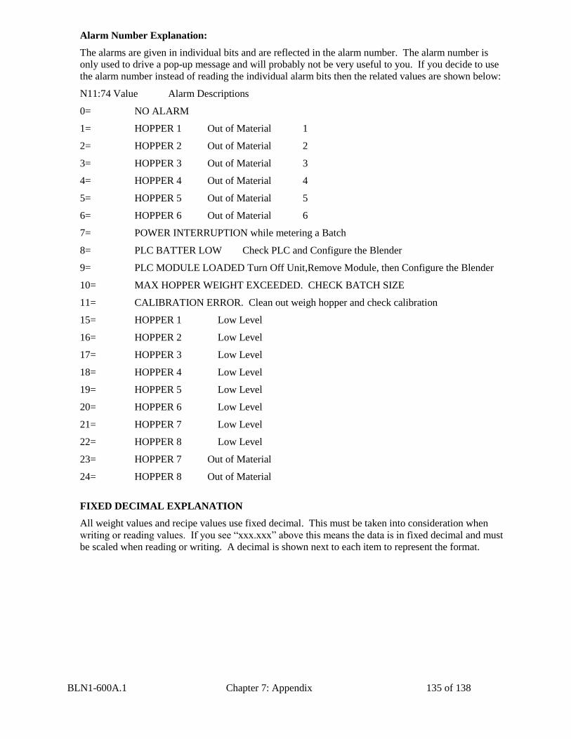
BLN1-600A.1 Chapter 7: Appendix 135 of 138
Alarm Number Explanation:
The alarms are given in individual bits and are reflected in the alarm number. The alarm number is
only used to drive a pop-up message and will probably not be very useful to you. If you decide to use
the alarm number instead of reading the individual alarm bits then the related values are shown below:
N11:74 Value Alarm Descriptions
0= NO ALARM
1= HOPPER 1 Out of Material 1
2= HOPPER 2 Out of Material 2
3= HOPPER 3 Out of Material 3
4= HOPPER 4 Out of Material 4
5= HOPPER 5 Out of Material 5
6= HOPPER 6 Out of Material 6
7= POWER INTERRUPTION while metering a Batch
8= PLC BATTER LOW Check PLC and Configure the Blender
9= PLC MODULE LOADED Turn Off Unit,Remove Module, then Configure the Blender
10= MAX HOPPER WEIGHT EXCEEDED. CHECK BATCH SIZE
11= CALIBRATION ERROR. Clean out weigh hopper and check calibration
15= HOPPER 1 Low Level
16= HOPPER 2 Low Level
17= HOPPER 3 Low Level
18= HOPPER 4 Low Level
19= HOPPER 5 Low Level
20= HOPPER 6 Low Level
21= HOPPER 7 Low Level
22= HOPPER 8 Low Level
23= HOPPER 7 Out of Material
24= HOPPER 8 Out of Material
FIXED DECIMAL EXPLANATION
All weight values and recipe values use fixed decimal. This must be taken into consideration when
writing or reading values. If you see “xxx.xxx” above this means the data is in fixed decimal and must
be scaled when reading or writing. A decimal is shown next to each item to represent the format.
BLN1-600A.1 Chapter 7: Appendix 136 of 138
WRITING RECIPE EXPLANATION
To write a recipe you must first write to the “temp recipe” value locations above. After this is
complete you should read the “accept recipe enabled” and the “recipe error” values. If you have a
recipe error then you should display the appropriate text. If the “accept recipe enabled” is high then
show a button that will then write to “accept recipe” bit. This will load in the recipe. You do not need
to check the sum of the recipe that they’ve entered. The blender will do that for you.
RECORDING THE TARGETS VS. ACTUALS FOR EACH BATCH
The targets that are read are in lbs or kgs. When a batch is complete and dumped the blender will
toggle high the “print data now” bit. At this time you should then read the “actual displayed weights”
values and record them into a log or chart. If you are not getting the “print now” bit, then refer to the
blender manual to configure “print batch data”.
INVENTORY EXPLANATION
In order to keep track of very large numbers while accurately keeping track of small increments the
blender uses two numbers for each inventory value. One number is the “whole” portion of the
inventory and the other is the “decimal” portion of the inventory in 3 decimal places. Most people
choose to ignore the decimal portion, but it’s there to provide additional accuracy. An example is
given below:
Whole portion value: 12345
Decimal (or Fractional) portion value: 678
This would represent 12345.678 lbs or kgs.
If you chose to write the recipe to the raw recipe locations you run the risk
of inadvertently entering the incorrect recipe. This is not recommended
because it will bypass all the checks that the blender makes before letting
you hit “accept new recipe”. Also if you chose to use the raw method then
you must add up the totals for your recipe and write that at the exact same
time that you write the other raw recipe values. You must also right the
batch size and recipe entry information or the blender might not make a
batch.
WHEN THE BLENDER IS NOT RUNNING THE “TARGET” VALUES
GET SET TO “999999999” AND IN THE BEGINNING OF EACH BATCH
ALL ACTUAL VALUES GET SET TO “999999999” UNTIL THE
HOPPER FEEDS MATERIAL INTO THE NEW BATCH.
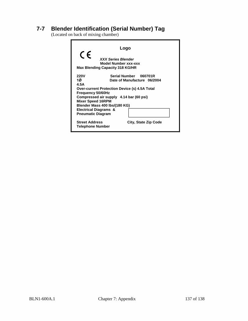
BLN1-600A.1 Chapter 7: Appendix 137 of 138
7-7 Blender Identification (Serial Number) Tag (Located on back of mixing chamber)
Logo
XXX Series Blender
Model Number xxx-xxx Max Blending Capacity 318 KG/HR 220V Serial Number 060701R 1Ǿ Date of Manufacture 06/2004 4.5A Over-current Protection Device (s) 4.5A Total Frequency 50/60Hz Compressed air supply 4.14 bar (60 psi) Mixer Speed 16RPM Blender Mass 400 lbs/(180 KG) Electrical Diagrams & Pneumatic Diagram Street Address City, State Zip Code Telephone Number
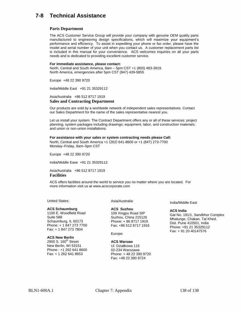
BLN1-600A.1 Chapter 7: Appendix 138 of 138
7-8 Technical Assistance
Parts Department
The ACS Customer Service Group will provide your company with genuine OEM quality parts manufactured to engineering design specifications, which will maximize your equipment’s performance and efficiency. To assist in expediting your phone or fax order, please have the model and serial number of your unit when you contact us. A customer replacement parts list is included in this manual for your convenience. ACS welcomes inquiries on all your parts needs and is dedicated to providing excellent customer service. For immediate assistance, please contact:
North, Central and South America, 8am – 5pm CST +1 (800) 483-3919. North America, emergencies after 5pm CST (847) 439-5855 Europe +48 22 390 9720 India/Middle East +91 21 35329112 Asia/Australia +86 512 8717 1919
Sales and Contracting Department
Our products are sold by a worldwide network of independent sales representatives. Contact our Sales Department for the name of the sales representative nearest you. Let us install your system. The Contract Department offers any or all of these services: project planning; system packages including drawings; equipment, labor, and construction materials; and union or non-union installations.
For assistance with your sales or system contracting needs please Call:
North, Central and South America +1 (262) 641-8600 or +1 (847) 273-7700 Monday–Friday, 8am–5pm CST Europe +48 22 390 9720 India/Middle Ease +91 21 35329112 Asia/Australia +86 512 8717 1919
Facilities
ACS offers facilities around the world to service you no matter where you are located. For more information visit us at www.acscorporate.com
United States: ACS Schaumburg
1100 E. Woodfield Road Suite 588 Schaumburg, IL 60173 Phone: + 1 847 273 7700 Fax: + 1 847 273 7804 ACS New Berlin
2900 S. 160th
Street New Berlin, WI 53151 Phone : +1 262 641 8600 Fax: + 1 262 641 8653
India/Middle East ACS India
Gat No. 191/1, Sandbhor Complex Mhalunge, Chakan, Tal Khed, Dist. Pune 410501, India Phone: +91 21 35329112 Fax: + 91 20 40147576
Asia/Australia: ACS Suzhou
109 Xingpu Road SIP Suzhou, China 215126 Phone: + 86 8717 1919 Fax: +86 512 8717 1916 Europe: ACS Warsaw
Ul. Działkowa 115 02-234 Warszawa Phone: + 48 22 390 9720 Fax: +48 22 390 9724