Embed Size (px)
Citation preview

Owner/Operator Manual
Models
927060 - 1028927062 - 1232927064 - 1440
Rear-Engine Rider
02777600E 5/03Supersedes 02777600, A–D
Printed in USA
ENGLISH
FRANÇAIS
ESPAÑOL
Transfer model &
serial number label from
product reg-istration here.
Coller l’autocollant du modèle et du numéro de série dans cet encadré.
Transferir aquí la etiqueta del modelo y número de serie del registro del producto.
GB - 2
Safety . . . . . . . . . . . . . . . . . . . . . . . . . . . . . . 3
Assembly . . . . . . . . . . . . . . . . . . . . . . . . . . . 8
Operation . . . . . . . . . . . . . . . . . . . . . . . . . . . 9
Maintenance Schedule . . . . . . . . . . . . . . . 12
Service and Adjustments . . . . . . . . . . . . . 14
Storage . . . . . . . . . . . . . . . . . . . . . . . . . . . 22
Troubleshooting. . . . . . . . . . . . . . . . . . . . 23
Service Parts . . . . . . . . . . . . . . . . . . . . . . 24
Specifications . . . . . . . . . . . . . . . . . . . . . 25
Warranty . . . . . . . . . . . . . . . . . . . . . . . . . . 26
THE MANUAL
Before operation of unit, carefully and completely read your manuals. The contents will provide you with an understanding of safety instructions and controls during normal operation and maintenance.All reference to left, right, front, or rear are given from operator seated in operation position and facing the direction of forward travel.
MODEL AND SERIAL NUMBERS
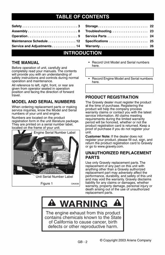
When ordering replacement parts or making service inquiries, know the Model and Serial numbers of your unit and engine.Numbers are located on the product registration form in the unit literature package. They are printed on a serial number label, located on the frame of your unit.
• Record Unit Model and Serial numbers here.
• Record Engine Model and Serial numbers here.
PRODUCT REGISTRATION
The Gravely dealer must register the product at the time of purchase. Registering the product will help the company process warranty claims or contact you with the latest service information. All claims meeting requirements during the limited warranty period will be honored, whether or not the product registration card is returned. Keep a proof of purchase if you do not register your unit.
Customer Note:
If the dealer does not register your product, please fill out, sign, and return the product registration card to Gravely or go to www.gravely.com.
UNAUTHORIZED REPLACEMENT PARTS
Use only Gravely replacement parts. The replacement of any part on this unit with anything other than a Gravely authorized replacement part may adversely affect the performance, durability, and safety of this unit and may void the warranty. Gravely disclaims liability for any claims or damages, whether warranty, property damage, personal injury or death arising out of the use of unauthorized replacement parts.
TABLE OF CONTENTS
INTRODUCTION
OA0038
Engine Serial Number Label
Figure 1
Unit Serial Number Label
The engine exhaust from this productcontains chemicals known to the State
of California to cause cancer, birthdefects or other reproductive harm.
WARNING
© Copyright 2003 Ariens Company

GB - 3
DELIVERY
Customer Note:
If you have purchased this product without complete assembly and instruction by your retailer, it is your responsibility to:
• Read and understand all assembly instructions in this manual. If you do not understand or have difficulty following the instructions, contact your nearest Ariens Dealer for assistance.
NOTE:
To locate your nearest Gravely Dealer, call 1-800-472-8359 or go to www.gravely.com on the internet.
Before attempting to operate your unit:
1. Make sure all assembly has been properly completed.
2. Understand all Safety Precautions provided in the manuals.
3. Review control functions and operation of the unit. Do not operate the unit unless all controls function as described in this manual.
4. Review recommended lubrication, maintenance and adjustments.
5. Review Limited Warranty Policy.6. Fill out a Product Registration Card and
return the card to the Ariens Company or go to www.gravely.com.
DISCLAIMER
Gravely reserves the right to discontinue, change, and improve its products at any time without notice or obligation to the purchaser. The descriptions and specifications contained in this manual were in effect at printing. Equipment described within this manual may be optional. Some illustrations may not be applicable to your unit.
SAFETY ALERTS
The safety alert symbol is used in decals and with this manual. Understand the safety message. It contains important information about personal safety.
NOTATIONS
NOTE:
General reference information for proper operation and maintenance practices.
IMPORTANT:
Specific procedures or information required to prevent damage to unit or attachment.
SAFETY DECALS AND LOCATIONS
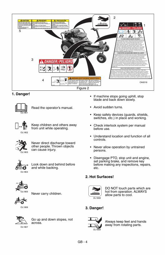
ALWAYS replace missing or damaged Safety Decals. Refer to figure 2 for Safety Decal locations.
WARNING:
Improper assembly or adjustments can cause serious injury.
SAFETY
WARNING:
This cutting machine is capable of amputating hands and feet and throwing objects. Failure to observe the safety instructions in the manuals and on decals could result in serious injury or death.Slopes are a major factor related to loss-of-control and tip-over accidents. Operation on all slopes requires extra caution.Tragic accidents can occur if the operator is not alert to the presence of children. Never assume that children will remain where you last saw them.Gasoline is extremely flammable and the vapors are explosive, handle with care.Disengage attachment, stop unit and engine, remove key, engage parking brake, and allow moving parts to stop before leaving operator’s position.
Look for these symbols to point out important safety precautions. They mean:
• Attention!• Personal Safety Is
Involved!• Become Alert! • Obey The Message!
DANGER:
IMMINENTLY HAZARDOUS SITUATION! If not avoided, WILL RESULT in death or serious injury.
WARNING:
POTENTIALLY HAZARDOUS SITUATION! If not avoided, COULD RESULT in death or serious injury.
CAUTION:
POTENTIALLY HAZARDOUS SITUATION! If not avoided, MAY RESULT in minor or moderate injury. It may also be used to alert against unsafe practices.
GB - 4
1. Danger!
2. Hot Surfaces!
3. Danger!
DANGER/PELIGRO
07731400D
0530
5000
A• Poids maximum du timon: 30 livres.• Poids maximum de la remorque: 300 livres.• Ne pas utiliser l'attelage lorsque l'ensacheuse est
posée.• Ne pas utiliser sur les pentes abruptes.• Ne pas stationner en pente quand la remorque est
attelée.• Ne pas utiliser avec un outil s'enfonçant dans le sol.
• Maximum tonque weight: 30 lbs.• Maximum trailer weight: 300 lbs.• Do not use hitch with bagger attached.• Do not use on steep hills or slopes.• Do not park on hills when trailer is
attached.• Do not use with any ground
engaging equipment.
• Peso máximo de la lengüeta: 30 lbs.• Peso máximo del remolque: 300 lbs.• No usar el enganche con la embosaldora
acoplada.• No usar en colinas o pendientes empinadas.• No estacionarse en colinas cuando el remolque
está acoplado.• No usar con equipo de manipulación del suelo.
CAUTION PRUDENCE PRECAUCIÓN
WARNING/AVERTISSEMENT/ADVERTENCIADo not operate mowerunless guards are inoperating position orbagger is attached.
Ne jamais utiliserla tondeuse sansprotecteur sur lecanal d'ejection ousans le bac monte.
No operar segadora amenos que las defensasesten en posicion deoperacion o elrecogedor este fijo.07742300B
Figure 2
OA00164
3
2
1
5
Read the operator’s manual.
Keep children and others away from unit while operating.
Never direct discharge toward other people. Thrown objects can cause injury.
Look down and behind before and while backing.
Never carry children.
Go up and down slopes, not across.
OL1801
OL1802
OL1803
OL1804
OL1805
OL1806
MAX10
OL1807
• If machine stops going uphill, stop blade and back down slowly.
• Avoid sudden turns.
• Keep safety devices (guards, shields, switches, etc.) in place and working.
• Check interlock system per manual before use.
• Understand location and function of all controls.
• Never allow operation by untrained persons.
• Disengage PTO, stop unit and engine, set parking brake, and remove key before making any inspections, repairs, etc.
DO NOT touch parts which are hot from operation. ALWAYS allow parts to cool.
Always keep feet and hands away from rotating parts.
OL1808
OL1809
GB - 5
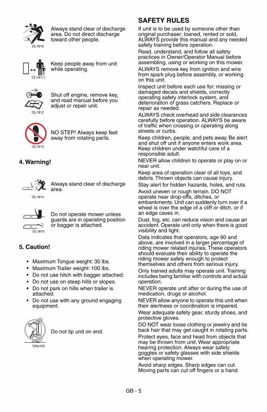
4. Warning!
5. Caution!
SAFETY RULES
If unit is to be used by someone other than original purchaser; loaned, rented or sold, ALWAYS provide this manual and any needed safety training before operation.Read, understand, and follow all safety practices in Owner/Operator Manual before assembling, using or working on this mower.ALWAYS remove key from ignition and wire from spark plug before assembly, or working on this unit.Inspect unit before each use for: missing or damaged decals and shields, correctly operating safety interlock system, and deterioration of grass catchers. Replace or repair as needed.ALWAYS check overhead and side clearances carefully before operation. ALWAYS be aware of traffic when crossing or operating along streets or curbs.Keep children, people, and pets away. Be alert and shut off unit if anyone enters work area. Keep children under watchful care of a responsible adult.NEVER allow children to operate or play on or near unit.Keep area of operation clear of all toys, and debris. Thrown objects can cause injury.Stay alert for hidden hazards, holes, and ruts.Avoid uneven or rough terrain. DO NOT operate near drop-offs, ditches, or embankments. Unit can suddenly turn over if a wheel is over the edge of a cliff or ditch, or if an edge caves in.Dust, fog, etc. can reduce vision and cause an accident. Operate unit only when there is good visibility and light.Data indicates that operators, age 60 and above, are involved in a larger percentage of riding mower related injuries. These operators should evaluate their ability to operate the riding mower safely enough to protect themselves and others from serious injury.Only trained adults may operate unit. Training includes being familiar with controls and actual operation.NEVER operate unit after or during the use of medication, drugs or alcohol. NEVER allow anyone to operate this unit when their alertness or coordination is impaired.Wear adequate safety gear, sturdy shoes, and protective gloves. DO NOT wear loose clothing or jewelry and tie back hair that may get caught in rotating parts.Protect eyes, face and head from objects that may be thrown from unit. Wear appropriate hearing protection. Always wear safety goggles or safety glasses with side shields when operating mower. Avoid sharp edges. Sharp edges can cut. Moving parts can cut off fingers or a hand.
Always stand clear of discharge area. Do not direct discharge toward other people.
Keep people away from unit while operating.
Shut off engine, remove key, and read manual before you adjust or repair unit.
NO STEP! Always keep feet away from rotating parts.
Always stand clear of discharge area.
Do not operate mower unless guards are in operating position or bagger is attached.
• Maximum Tongue weight: 30 lbs.• Maximum Trailer weight: 100 lbs.• Do not use hitch with bagger attached.• Do not use on steep hills or slopes.• Do not park on hills when trailer is
attached.• Do not use with any ground engaging
equipment.
Do not tip unit on end.
OL1810
OL18111
OL1812
OL1813
OL1814
OL1815
OAa100
GB - 6
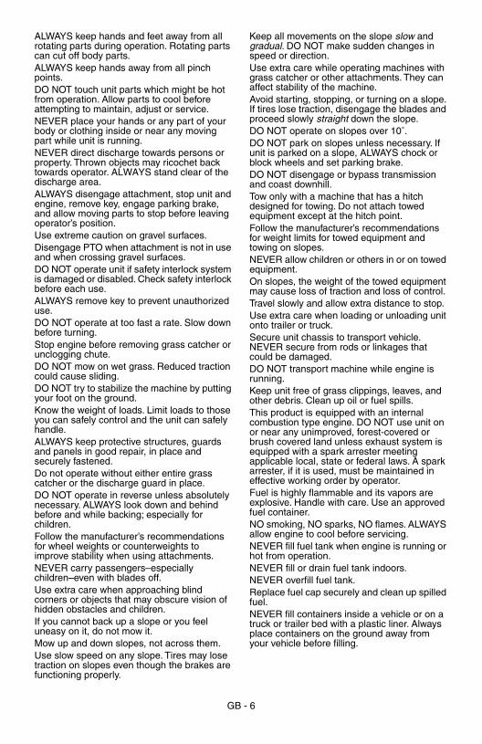
ALWAYS keep hands and feet away from all rotating parts during operation. Rotating parts can cut off body parts.ALWAYS keep hands away from all pinch points.DO NOT touch unit parts which might be hot from operation. Allow parts to cool before attempting to maintain, adjust or service. NEVER place your hands or any part of your body or clothing inside or near any moving part while unit is running.NEVER direct discharge towards persons or property. Thrown objects may ricochet back towards operator. ALWAYS stand clear of the discharge area. ALWAYS disengage attachment, stop unit and engine, remove key, engage parking brake, and allow moving parts to stop before leaving operator’s position.Use extreme caution on gravel surfaces. Disengage PTO when attachment is not in use and when crossing gravel surfaces.DO NOT operate unit if safety interlock system is damaged or disabled. Check safety interlock before each use.ALWAYS remove key to prevent unauthorized use.DO NOT operate at too fast a rate. Slow down before turning.Stop engine before removing grass catcher or unclogging chute.DO NOT mow on wet grass. Reduced traction could cause sliding.DO NOT try to stabilize the machine by putting your foot on the ground.Know the weight of loads. Limit loads to those you can safely control and the unit can safely handle.ALWAYS keep protective structures, guards and panels in good repair, in place and securely fastened.Do not operate without either entire grass catcher or the discharge guard in place.DO NOT operate in reverse unless absolutely necessary. ALWAYS look down and behind before and while backing; especially for children.Follow the manufacturer’s recommendations for wheel weights or counterweights to improve stability when using attachments.NEVER carry passengers–especially children–even with blades off.Use extra care when approaching blind corners or objects that may obscure vision of hidden obstacles and children.If you cannot back up a slope or you feel uneasy on it, do not mow it.Mow up and down slopes, not across them.Use slow speed on any slope. Tires may lose traction on slopes even though the brakes are functioning properly.
Keep all movements on the slope
slow
and
gradual.
DO NOT make sudden changes in speed or direction.Use extra care while operating machines with grass catcher or other attachments. They can affect stability of the machine.Avoid starting, stopping, or turning on a slope. If tires lose traction, disengage the blades and proceed slowly
straight
down the slope.DO NOT operate on slopes over 10˚.DO NOT park on slopes unless necessary. If unit is parked on a slope, ALWAYS chock or block wheels and set parking brake.DO NOT disengage or bypass transmission and coast downhill.Tow only with a machine that has a hitch designed for towing. Do not attach towed equipment except at the hitch point.Follow the manufacturer’s recommendations for weight limits for towed equipment and towing on slopes.NEVER allow children or others in or on towed equipment.On slopes, the weight of the towed equipment may cause loss of traction and loss of control.Travel slowly and allow extra distance to stop.Use extra care when loading or unloading unit onto trailer or truck.Secure unit chassis to transport vehicle. NEVER secure from rods or linkages that could be damaged.DO NOT transport machine while engine is running. Keep unit free of grass clippings, leaves, and other debris. Clean up oil or fuel spills.This product is equipped with an internal combustion type engine. DO NOT use unit on or near any unimproved, forest-covered or brush covered land unless exhaust system is equipped with a spark arrester meeting applicable local, state or federal laws. A spark arrester, if it is used, must be maintained in effective working order by operator.Fuel is highly flammable and its vapors are explosive. Handle with care. Use an approved fuel container.NO smoking, NO sparks, NO flames. ALWAYS allow engine to cool before servicing.NEVER fill fuel tank when engine is running or hot from operation.NEVER fill or drain fuel tank indoors.NEVER overfill fuel tank.Replace fuel cap securely and clean up spilled fuel.NEVER fill containers inside a vehicle or on a truck or trailer bed with a plastic liner. Always place containers on the ground away from your vehicle before filling.

GB - 7
When practical, remove gas-powered equipment from the truck or trailer and refuel it on the ground. If this is not possible, then refuel such equipment on a trailer with a portable container, rather than from a gasoline dispenser nozzle.Keep the nozzle in contact with the rim of the fuel tank or container opening at all times until fueling is complete. Do not use a nozzle lock-open device.If fuel is spilled on clothing, change clothing immediately.Avoid Electric Shock. Objects contacting both battery terminals at the same time may result in injury and unit damage. DO NOT reverse battery connections.Explosive Gases from battery can cause death or serious injury. Poisonous battery fluid contains sulfuric acid and its contact with skin, eyes or clothing can cause severe chemical burns.NO flames, NO sparks, NO smoking near battery.ALWAYS wear safety glasses and protective gear near battery.DO NOT TIP battery beyond a 45˚ angle in any direction.ALWAYS keep batteries out of reach of children.Battery posts, terminals and related accessories contain lead and lead compounds, chemicals known to the State of California to cause cancer and reproductive harm. Wash hands after handling.Reverse connections may result in sparks which can cause serious injury. Always connect positive (+) lead of charger to positive (+) terminal, and negative (-) lead to negative (-) terminal.ALWAYS disconnect negative (-) cable FIRST and positive (+) cable SECOND. ALWAYS connect positive (+) cable FIRST, and negative (-) cable SECOND.
A frozen battery can explode and result in death or serious injury. DO NOT charge or jump start a battery containing frozen fluid. Thaw the battery before putting on a charger or jump starting.ALWAYS keep protective structures, guards, and panels in good repair, in place and securely fastened. NEVER modify or remove safety devices.DO NOT change engine governor settings or over-speed engine. Fumes from engine exhaust can cause injury or death. DO NOT run engine in an enclosed area. Always provide good ventilation.ALWAYS maintain unit in safe operating condition. Damaged or worn out muffler can cause fire or explosion.Stop and inspect equipment if you strike an object or if there is an unusual vibration. Repair, if necessary, before restarting. Never make adjustments or repairs with the engine running.Mower blades are sharp and can cut you. Wrap the blade(s) or wear gloves, and use extra caution when servicing them. NEVER weld or straighten mower blades.Rotation of one blade may cause rotation of the other blades.Check brake operation frequently. Adjust and service as required.Keep all hardware properly tightened.Stored energy in springs can cause injury.Maintain or replace safety and instruction labels, as necessary.Never store the machine or fuel container inside a building where there is an open flame, such as a water heater.Allow engine to cool completely before storing in closed area or covering unit.For extended storage, clean unit thoroughly. See Engine Manual for proper storage.Use only attachments or accessories designed for your unit.Check attachment components frequently. If worn or damaged, replace with manufacturer’s recommended parts.
GB - 8
TOOLS REQUIRED
• Adjustable wrench• Petroleum jelly or dielectric grease.
UNPACK UNIT
Remove unit and all other components from the shipping container. Engage transmission bypass lever (see
Moving The Unit Manually
on page 11). Push unit from container onto a level surface. Disengage transmission bypass lever.
FIRST TIME USE
1. Install steering wheel.2. Connect negative battery cable to battery.
See
Battery Removal and Installation
on page 19 and perform step 1 in the removal section and perform steps 3, 4, and 6 in the installation section.
3. Check oil (see
Check Engine Oil
in
Maintenance Schedule
on page 12).4. Check tire pressure (see
Specifications
on page 25).
5. Fill fuel tank (see
Filling Fuel Tank
on page 10).
6. Adjust seat (see
Seat Adjustment
on page 11).
7. Check safety interlock system (see
Safety Interlock System
on page 9).8. Check level and pitch of mower deck (see
Leveling Mower Deck and Adjusting Mower Deck Pitch
on page 15 and
Adjusting Mower Deck Pitch
on page 16).9. Check function of all controls (see
Operation
on page 9).
ASSEMBLY
WARNING:
AVOID INJURY. Read and understand the entire
Safety
section before proceeding.

GB - 9
CONTROLS AND FEATURES (FIGURE 3)
Safety Interlock System
Perform the following tests to ensure the safety interlock system is working properly. If the unit does not perform as stated, contact your Gravely dealer for repairs.
NOTE:
With the parking brake engaged, the steering levers are locked in neutral.
Ignition Switch (Item 5)
Operated by a removable key:1. Stop2. Run3. Start
OPERATION
WARNING:
AVOID INJURY. Read and understand the entire
Safety
section before proceeding.
Figure 3 OA0016
1. Seat2. Forward and
Reverse Pedal3. Throttle Lever4. PTO Switch5. Ignition Switch
6. Mower Deck7. Parking Brake8. Steering Wheel9. Discharge Chute10. Mower Lift Lever11. Fuel Tank
1
4
5
3
7
8
2
10
6
9
11
WARNING:
Safety interlock failure and improper operation of unit can result in death or serious injury. Check system before each use to make sure it is functioning properly.
Test Forward and
Reverse Pedal
PTO Parking Brake
Engine
1 Neutral Off Engaged Starts
2 Forward Off Engaged Doesn’t Start
3 Reverse Off Engaged Doesn’t Start
4 Neutral On Engaged Doesn’t Start
5 Neutral Off Disengaged Doesn’t Start
6* Forward Off Engaged Shuts Off
7* Reverse Off Engaged Shuts Off
8*+ Neutral On Disengaged Shuts Off
9*+ Neutral Off Disengaged Shuts Off
10*+ Neutral Off Engaged Runs
*Test with engine running.+Operator lifts off seat.
OFF
START
RUN
12
3
OA0004
GB - 10
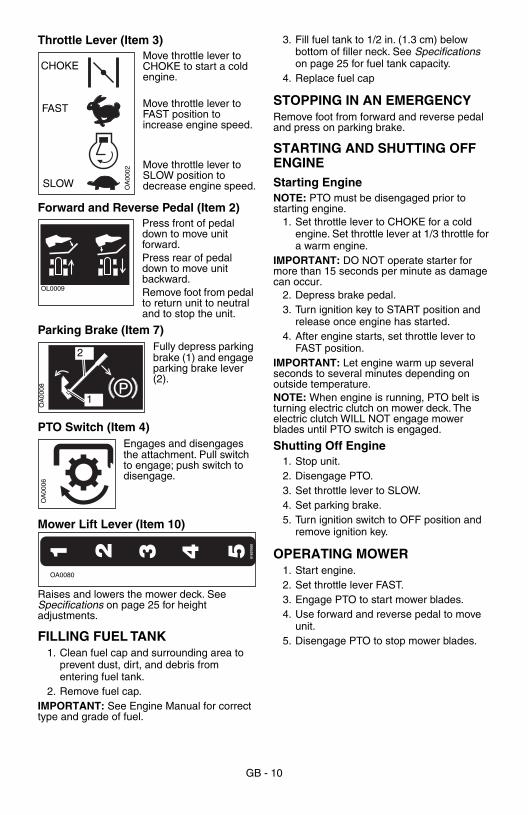
Throttle Lever (Item 3)
Move throttle lever to CHOKE to start a cold engine.
Move throttle lever to FAST position to increase engine speed.
Move throttle lever to SLOW position to decrease engine speed.
Forward and Reverse Pedal (Item 2)
Press front of pedal down to move unit forward.Press rear of pedal down to move unit backward.Remove foot from pedal to return unit to neutral and to stop the unit.
Parking Brake (Item 7)
Fully depress parking brake (1) and engage parking brake lever (2).
PTO Switch (Item 4)
Engages and disengages the attachment. Pull switch to engage; push switch to disengage.
Mower Lift Lever (Item 10)
Raises and lowers the mower deck. See
Specifications
on page 25 for height adjustments.
FILLING FUEL TANK
1. Clean fuel cap and surrounding area to prevent dust, dirt, and debris from entering fuel tank.
2. Remove fuel cap.
IMPORTANT:
See Engine Manual for correct type and grade of fuel.
3. Fill fuel tank to 1/2 in. (1.3 cm) below bottom of filler neck. See
Specifications
on page 25 for fuel tank capacity.4. Replace fuel cap
STOPPING IN AN EMERGENCY
Remove foot from forward and reverse pedal and press on parking brake.
STARTING AND SHUTTING OFF ENGINE
Starting Engine
NOTE:
PTO must be disengaged prior to starting engine.
1. Set throttle lever to CHOKE for a cold engine. Set throttle lever at 1/3 throttle for a warm engine.
IMPORTANT:
DO NOT operate starter for more than 15 seconds per minute as damage can occur.
2. Depress brake pedal.3. Turn ignition key to START position and
release once engine has started.4. After engine starts, set throttle lever to
FAST position.
IMPORTANT:
Let engine warm up several seconds to several minutes depending on outside temperature.
NOTE:
When engine is running, PTO belt is turning electric clutch on mower deck. The electric clutch WILL NOT engage mower blades until PTO switch is engaged.
Shutting Off Engine
1. Stop unit.2. Disengage PTO.3. Set throttle lever to SLOW.4. Set parking brake.5. Turn ignition switch to OFF position and
remove ignition key.
OPERATING MOWER
1. Start engine.2. Set throttle lever FAST.3. Engage PTO to start mower blades.4. Use forward and reverse pedal to move
unit.5. Disengage PTO to stop mower blades.
CHOKE
FAST
SLOW OA
0002
OL0009
OA
0008
1
2
OA
0006
1 2 3 4 5 0160
7000
OA0080
GB - 11
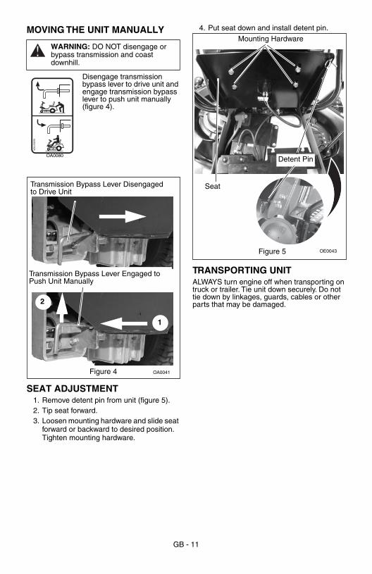
MOVING THE UNIT MANUALLY
Disengage transmission bypass lever to drive unit and engage transmission bypass lever to push unit manually (figure 4).
SEAT ADJUSTMENT
1. Remove detent pin from unit (figure 5).2. Tip seat forward.3. Loosen mounting hardware and slide seat
forward or backward to desired position. Tighten mounting hardware.
4. Put seat down and install detent pin.
TRANSPORTING UNIT
ALWAYS turn engine off when transporting on truck or trailer. Tie unit down securely. Do not tie down by linkages, guards, cables or other parts that may be damaged.
WARNING:
DO NOT disengage or bypass transmission and coast downhill.
05305700A
OA0080
OA0041Figure 4
Transmission Bypass Lever Engaged to Push Unit Manually
1
2
Transmission Bypass Lever Disengaged to Drive Unit
OE0043
Mounting Hardware
Seat
Detent Pin
Figure 5
GB - 12
IMPORTANT:
Proper maintenance can prolong the life of unit. The following chart
shows the recommended service schedule. Refer to the maintenance instructions in the Engine Manual for additional information.
IMPORTANT:
Do not place unit on end.
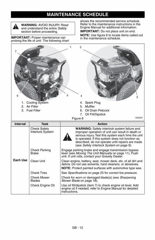
NOTE:
Use figure 6 to locate items called out in the maintenance schedule.
MAINTENANCE SCHEDULE
WARNING:
AVOID INJURY. Read and understand the entire
Safety
section before proceeding.
Figure 6 OA0042
1. Cooling System2. Air Filter3. Fuel Filter
4. Spark Plug5. Muffler6. Oil Drain Petcock7. Oil Fill/Dipstick
7
6
1
5 4 3
2
Interval Task Action
Each Use
Check Safety Interlock System
WARNING:
Safety interlock system failure and improper operation of unit can result in death or serious injury. Test this system each time the unit is operated. If this system does not function as described, do not operate until repairs are made (see
Safety Interlock System
on page 9).
Check Parking Brake
Engage parking brake and engage transmission bypass lever (see
Moving The Unit Manually
on page 11). Push unit. If unit rolls, contact your Gravely Dealer.
Clean Unit Clean engine, battery, seat, mower deck, etc. of all dirt and debris. Do not use solvents, hard cleaners, or abrasives.
NOTE:
Protect painted surfaces with automotive type wax.
Check Tires See
Specifications
on page 25 for correct tire pressure.
Check Mower Blades
Check for worn or damaged blade(s) (see
Sharpening Mower Blade
on page 18).
Check Engine Oil Use oil fill/dipstick (item 7) to check engine oil level. Add engine oil if needed, refer to Engine Manual for detailed instructions.
GB - 13
25 Hours or Every Season
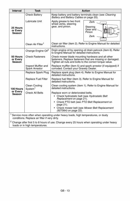
Check Battery Keep battery and battery terminals clean (see
Cleaning Battery and Battery Cables
on page 20).
Lubricate Unit Apply grease to two front wheel zerks, steering gear, and pinion.
Clean Air Filter
1
Clean air filter (item 2). Refer to Engine Manual for detailed instructions.
50 Hours or Every Season
Change Engine Oil
2 Drain engine oil by opening oil drain petcock (item 6). Refer to Engine Manual for detailed instructions.
Check Fasteners Check mower blade mounting hardware and all other fasteners. Replace fasteners that are missing or damaged. Tighten all nuts and bolts to the correct torque value.
Inspect Muffler and Spark Arrestor
Replace muffler (item 5) and spark arrestor (if equipped) if corroded. Contact your Gravely Dealer.
100 Hours or Every Season
Replace Spark Plug Replace spark plug (item 4). Refer to Engine Manual for detailed instructions.
Replace Fuel Filter Replace fuel filter (item 3). Refer to Engine Manual for detailed instructions.
Clean Cooling System1
Clean cooling system (item 1). Refer to Engine Manual for detailed instructions.
Check All Belts Replace worn or deteriorated belts.• Check hydrostatic belt (see Hydrostatic Belt
Replacement on page 21).• Check PTO belt (see PTO Belt Replacement on
page 21).• Check mower belt (see Mower Belt Replacement
(927064) on page 22). 1 Service more often when operating under heavy loads, high temperatures, or dusty
conditions. Replace air filter if very dirty.2 Change after first 5 to 8 hours of use. Change every 25 hours when operating under heavy
loads or in high temperatures.
Interval Task Action
Zerk
Steering Gear and Pinion
Zerk
GB - 14
REMOVING AND INSTALLING THE HOOD (927064)Two clamping knobs hold the hood to the unit. Turn clamping knobs counterclockwise to remove and clockwise to install (figure 7).
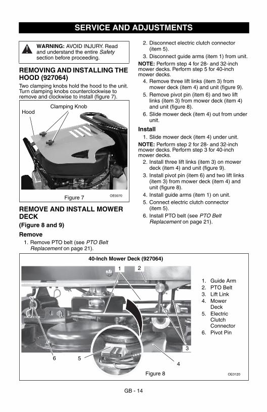
REMOVE AND INSTALL MOWER DECK(Figure 8 and 9)
Remove 1. Remove PTO belt (see PTO Belt
Replacement on page 21).
2. Disconnect electric clutch connector (item 5).
3. Disconnect guide arms (item 1) from unit.NOTE: Perform step 4 for 28- and 32-inch mower decks. Perform step 5 for 40-inch mower decks.
4. Remove three lift links (item 3) from mower deck (item 4) and unit (figure 9).
5. Remove pivot pin (item 6) and two lift links (item 3) from mower deck (item 4) and unit (figure 8).
6. Slide mower deck (item 4) out from under unit.
Install1. Slide mower deck (item 4) under unit.
NOTE: Perform step 2 for 28- and 32-inch mower decks. Perform step 3 for 40-inch mower decks.
2. Install three lift links (item 3) on mower deck (item 4) and unit (figure 9).
3. Install pivot pin (item 6) and two lift links (item 3) from mower deck (item 4) and unit (figure 8).
4. Install guide arms (item 1) on unit.5. Connect electric clutch connector
(item 5).6. Install PTO belt (see PTO Belt
Replacement on page 21).
SERVICE AND ADJUSTMENTS
WARNING: AVOID INJURY. Read and understand the entire Safety section before proceeding.
OE0070
Clamping KnobHood
Figure 7
OE0120
3
2
6 54
Figure 8
1
40-Inch Mower Deck (927064)
1. Guide Arm2. PTO Belt3. Lift Link4. Mower
Deck5. Electric
Clutch Connector
6. Pivot Pin
GB - 15
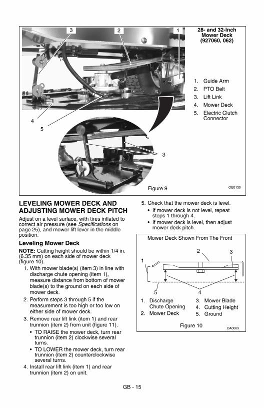
LEVELING MOWER DECK AND ADJUSTING MOWER DECK PITCHAdjust on a level surface, with tires inflated to correct air pressure (see Specifications on page 25), and mower lift lever in the middle position.
Leveling Mower DeckNOTE: Cutting height should be within 1/4 in. (6.35 mm) on each side of mower deck (figure 10).
1. With mower blade(s) (item 3) in line with discharge chute opening (item 1), measure distance from bottom of mower blade(s) to the ground on each side of mower deck.
2. Perform steps 3 through 5 if the measurement is too high or too low on either side of mower deck.
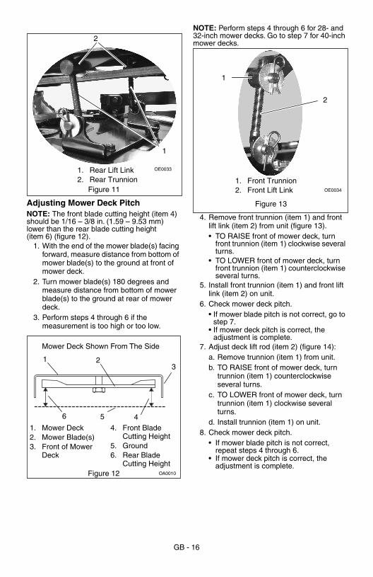
3. Remove rear lift link (item 1) and rear trunnion (item 2) from unit (figure 11).• TO RAISE the mower deck, turn rear
trunnion (item 2) clockwise several turns.
• TO LOWER the mower deck, turn rear trunnion (item 2) counterclockwise several turns.
4. Install rear lift link (item 1) and rear trunnion (item 2) on unit.
5. Check that the mower deck is level.• If mower deck is not level, repeat
steps 1 through 4.• If mower deck is level, then adjust
mower deck pitch.
OE0130
13 2
5
4
Figure 9
3
28- and 32-Inch Mower Deck (927060, 062)
1. Guide Arm
2. PTO Belt
3. Lift Link
4. Mower Deck
5. Electric Clutch Connector
OA0009
1
Mower Deck Shown From The Front
1. Discharge Chute Opening
2. Mower Deck
3. Mower Blade4. Cutting Height5. Ground
2 3
5 4
Figure 10
GB - 16
Adjusting Mower Deck PitchNOTE: The front blade cutting height (item 4) should be 1/16 – 3/8 in. (1.59 – 9.53 mm) lower than the rear blade cutting height (item 6) (figure 12).
1. With the end of the mower blade(s) facing forward, measure distance from bottom of mower blade(s) to the ground at front of mower deck.
2. Turn mower blade(s) 180 degrees and measure distance from bottom of mower blade(s) to the ground at rear of mower deck.
3. Perform steps 4 through 6 if the measurement is too high or too low.
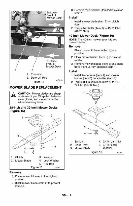
NOTE: Perform steps 4 through 6 for 28- and 32-inch mower decks. Go to step 7 for 40-inch mower decks.
4. Remove front trunnion (item 1) and front lift link (item 2) from unit (figure 13).• TO RAISE front of mower deck, turn
front trunnion (item 1) clockwise several turns.
• TO LOWER front of mower deck, turn front trunnion (item 1) counterclockwise several turns.
5. Install front trunnion (item 1) and front lift link (item 2) on unit.
6. Check mower deck pitch.• If mower blade pitch is not correct, go to
step 7.• If mower deck pitch is correct, the
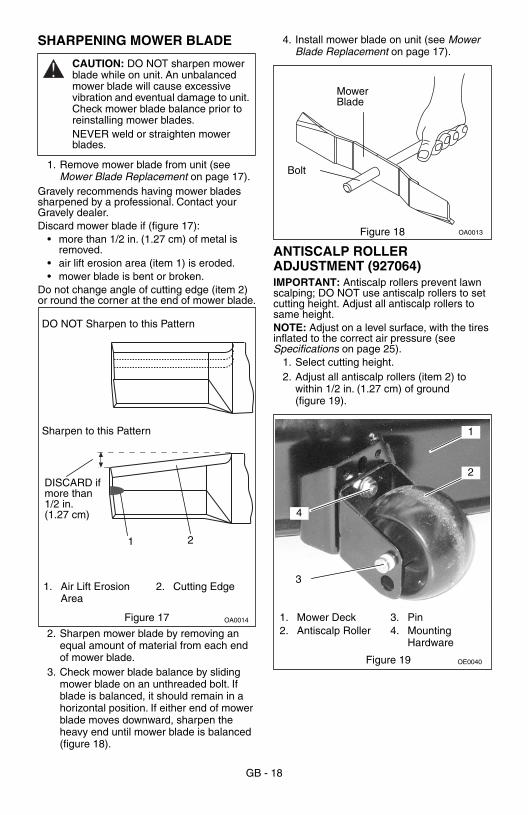
adjustment is complete.7. Adjust deck lift rod (item 2) (figure 14):
a. Remove trunnion (item 1) from unit.b. TO RAISE front of mower deck, turn
trunnion (item 1) counterclockwise several turns.
c. TO LOWER front of mower deck, turn trunnion (item 1) clockwise several turns.
d. Install trunnion (item 1) on unit.8. Check mower deck pitch.
• If mower blade pitch is not correct, repeat steps 4 through 6.
• If mower deck pitch is correct, the adjustment is complete.
1
Figure 11
1. Rear Lift Link2. Rear Trunnion
2
OE0033
Figure 12 OA0010
Mower Deck Shown From The Side
1. Mower Deck2. Mower Blade(s)3. Front of Mower
Deck
4. Front Blade Cutting Height
5. Ground6. Rear Blade
Cutting Height
1
5
2
46
3
Figure 13
2
1
1. Front Trunnion2. Front Lift Link OE0034
GB - 17
MOWER BLADE REPLACEMENT
28-Inch and 32-Inch Mower Decks (Figure 15)
Remove1. Place mower lift lever in the highest
position.2. Block mower blade (item 2) to prevent
rotation.
3. Remove mower blade (item 2) from clutch (item 1).
Install1. Install mower blade (item 2) on clutch
(item 1). 2. Torque hex bolts (item 5) to 45-55 lbf-ft
(61-75 N•m).
40-Inch Mower Deck (Figure 16)NOTE: The 40-inch mower deck has two mower blades.
Remove1. Place mower lift lever in the highest
position.2. Block mower blades (item 3) to prevent
rotation.3. Remove mower blades (item 3) and blade
trays (item 2) from spindles (item 1).
Install1. Install blade trays (item 2) and mower
blades (item 3) on spindles (item 1).2. Torque 3/4 in. jam nuts (item 4) to 48–
72 lbf-ft (65–97 N•m).
CAUTION: Mower blades are sharp and can cut you. Wrap the blades or wear gloves, and use extra caution when servicing them.
Figure 14
1 2
1. Trunnion2. Deck Lift Rod
OE0140
To Lower Front of Mower Deck
To Raise Front of Mower Deck
Figure 15 OA0011
1. Clutch2. Mower Blade
3. Washer4. Lock Washer5. Hex Bolt
3
12
4
5
54
3
1. Spindle2. Blade Tray3. Mower Blade
4. 3/4 in. Jam Nut5. 3/4 in. Lock
Washer
Figure 16 OA0012
1
2
3
4
5
GB - 18
SHARPENING MOWER BLADE
1. Remove mower blade from unit (see Mower Blade Replacement on page 17).
Gravely recommends having mower blades sharpened by a professional. Contact your Gravely dealer.Discard mower blade if (figure 17):
• more than 1/2 in. (1.27 cm) of metal is removed.
• air lift erosion area (item 1) is eroded.• mower blade is bent or broken.
Do not change angle of cutting edge (item 2) or round the corner at the end of mower blade.
2. Sharpen mower blade by removing an equal amount of material from each end of mower blade.
3. Check mower blade balance by sliding mower blade on an unthreaded bolt. If blade is balanced, it should remain in a horizontal position. If either end of mower blade moves downward, sharpen the heavy end until mower blade is balanced (figure 18).
4. Install mower blade on unit (see Mower Blade Replacement on page 17).
.
ANTISCALP ROLLER ADJUSTMENT (927064)IMPORTANT: Antiscalp rollers prevent lawn scalping; DO NOT use antiscalp rollers to set cutting height. Adjust all antiscalp rollers to same height.NOTE: Adjust on a level surface, with the tires inflated to the correct air pressure (see Specifications on page 25).
1. Select cutting height.2. Adjust all antiscalp rollers (item 2) to
within 1/2 in. (1.27 cm) of ground (figure 19).
CAUTION: DO NOT sharpen mower blade while on unit. An unbalanced mower blade will cause excessive vibration and eventual damage to unit. Check mower blade balance prior to reinstalling mower blades. NEVER weld or straighten mower blades.
1. Air Lift Erosion Area
2. Cutting Edge
Figure 17 OA0014
21
DO NOT Sharpen to this Pattern
Sharpen to this Pattern
DISCARD if more than 1/2 in. (1.27 cm)
Figure 18 OA0013
Bolt
Mower Blade
Figure 19
1. Mower Deck2. Antiscalp Roller
3. Pin4. Mounting
Hardware
OE0040
1
2
4
3
GB - 19
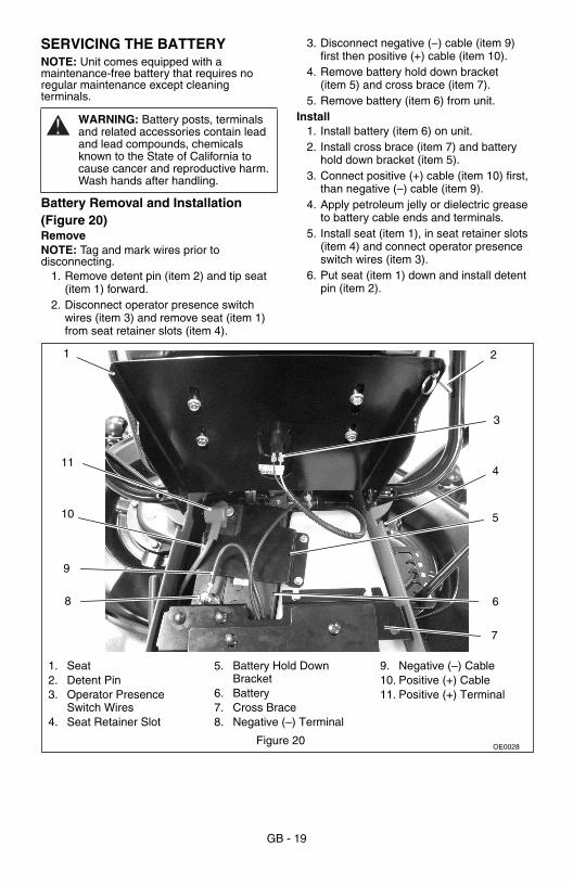
SERVICING THE BATTERYNOTE: Unit comes equipped with a maintenance-free battery that requires no regular maintenance except cleaning terminals.
Battery Removal and Installation(Figure 20)RemoveNOTE: Tag and mark wires prior to disconnecting.
1. Remove detent pin (item 2) and tip seat (item 1) forward.
2. Disconnect operator presence switch wires (item 3) and remove seat (item 1) from seat retainer slots (item 4).
3. Disconnect negative (–) cable (item 9) first then positive (+) cable (item 10).
4. Remove battery hold down bracket (item 5) and cross brace (item 7).
5. Remove battery (item 6) from unit.Install
1. Install battery (item 6) on unit.2. Install cross brace (item 7) and battery
hold down bracket (item 5).3. Connect positive (+) cable (item 10) first,
than negative (–) cable (item 9).4. Apply petroleum jelly or dielectric grease
to battery cable ends and terminals.5. Install seat (item 1), in seat retainer slots
(item 4) and connect operator presence switch wires (item 3).
6. Put seat (item 1) down and install detent pin (item 2).
WARNING: Battery posts, terminals and related accessories contain lead and lead compounds, chemicals known to the State of California to cause cancer and reproductive harm. Wash hands after handling.
OE0028
411
3
10
6
9
8
5
1 2
7
Figure 20
1. Seat2. Detent Pin3. Operator Presence
Switch Wires4. Seat Retainer Slot
5. Battery Hold Down Bracket
6. Battery7. Cross Brace8. Negative (–) Terminal
9. Negative (–) Cable10. Positive (+) Cable11. Positive (+) Terminal

GB - 20
Cleaning Battery and Battery Cables(Figure 20)
1. Remove battery from unit (see Battery Removal and Installation on page 19).
2. Clean or service battery away from unit. Remove corrosion from battery terminals and cable connections with wire brush, then wash with a weak baking soda solution.
3. Install battery on unit (see Battery Removal and Installation on page 19).
Charging the Battery(Figure 20)
Follow First Aid directions for contact with battery fluid.
• External Contact: Flush with water.• Eyes: Flush with water for at least 15
minutes and get medical attention immediately!
• Internal Contact: Drink large quantities of water. Follow with Milk of Magnesia, beaten egg or vegetable oil. Get medical attention immediately!
• In case of internal contact, DO NOT induce vomiting!
IMPORTANT: DO NOT fast charge. Charging at a higher rate will damage or destroy battery.IMPORTANT: ALWAYS follow information provided on battery and battery charger. Contact battery and battery charger manufacturers’ for detailed instructions.
1. Remove battery from unit (see Battery Removal and Installation on page 19).
2. Place battery on bench or other well-ventilated area.
3. Connect positive (+) lead of charger to positive (+) terminal (item 11), and negative (–) lead of charger tonegative (–) terminal (item 8).
4. Charge battery according to battery charger and battery manufacturers’ instructions.
5. Install battery on unit (see Battery Removal and Installation on page 19).
Jump Starting the Battery(Figure 20)IMPORTANT: The unit used for jump starting should have a 12 volt battery with at least 500 cold cranking amperes, and a negatively grounded system.
IMPORTANT: Ensure battery is not frozen. If battery is frozen, remove battery from unit and allow it to thaw before charging.
1. Connect positive (+) jumper cable to positive (+) terminal (item 11) of discharged battery.
2. Connect the other end of positive (+) jumper cable to positive (+) terminal of booster battery.
3. Connect negative (–) jumper cable to negative (–) terminal of the booster battery.
4. Connect the other end of negative (–) jumper cable to engine of unit with discharged battery.
NOTE: If engine will not start, unit or battery may need service.
5. Start engine.6. After engine starts, leave jumper cables
connected for one to two minutes.7. Disconnect jumper cables in reverse
order of installation.8. Operate unit as normal to charge battery.
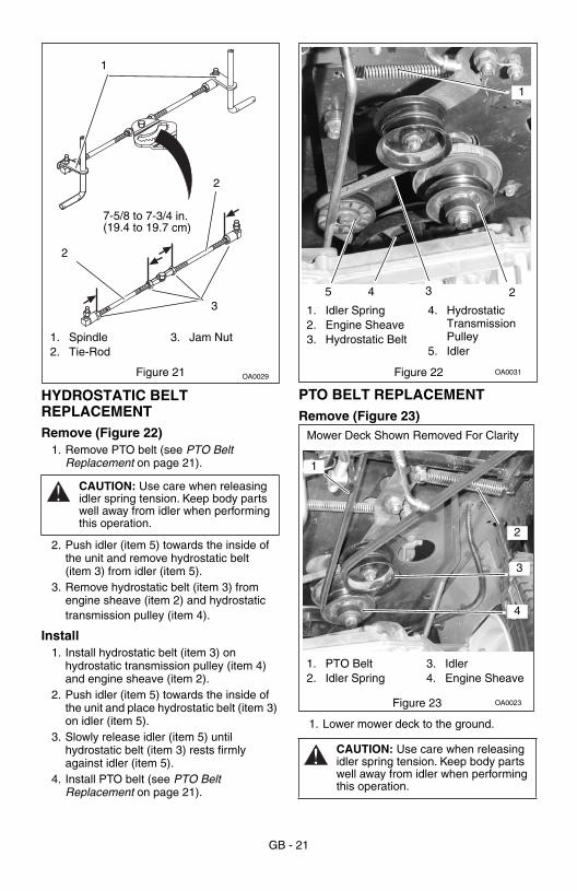
FRONT WHEEL ALIGNMENTCheck (Figure 21)NOTE: The distance between jam nuts (item 3) should be 7-5/8 to 7-3/4 in. (19.4 to 19.7 cm).
1. Measure the distance between jam nuts (item 3).
2. Adjust if needed.
Adjust (Figure 21)1. Remove tie-rod(s) (item 2) from spindle(s)
(item 1).2. Loosen jam nut(s) (item 3) and turn
tie-rod(s) (item 2) clockwise or counterclockwise until the distance between the jam nuts (item 3) is within specifications.
3. Tighten jam nuts (item 3).4. Install tie-rod(s) (item 2) on spindle(s)
(item 1).
WARNING: FROZEN BATTERIES CAN EXPLODE and result in death or serious injury. DO NOT charge a frozen battery. Let the battery thaw before charging.
WARNING: Make sure cables are clear of any moving engine parts before starting engine.
GB - 21
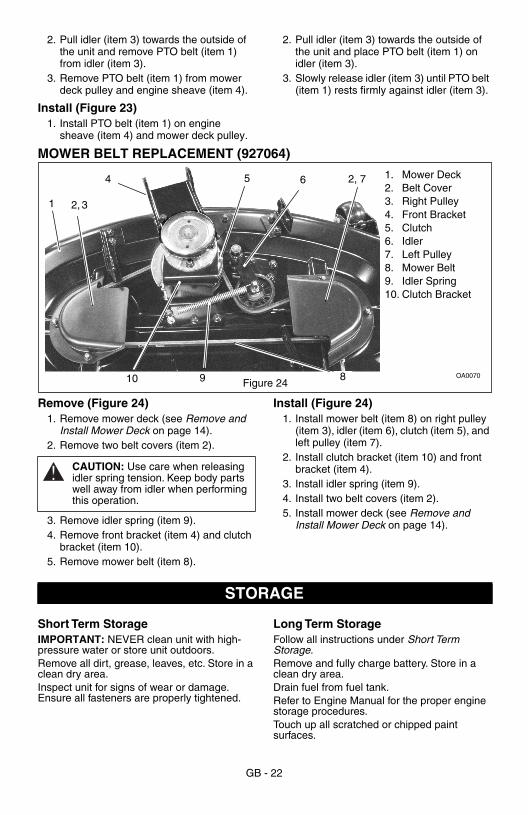
HYDROSTATIC BELT REPLACEMENTRemove (Figure 22)
1. Remove PTO belt (see PTO Belt Replacement on page 21).
2. Push idler (item 5) towards the inside of the unit and remove hydrostatic belt (item 3) from idler (item 5).
3. Remove hydrostatic belt (item 3) from engine sheave (item 2) and hydrostatic transmission pulley (item 4).
Install1. Install hydrostatic belt (item 3) on
hydrostatic transmission pulley (item 4) and engine sheave (item 2).
2. Push idler (item 5) towards the inside of the unit and place hydrostatic belt (item 3) on idler (item 5).
3. Slowly release idler (item 5) until hydrostatic belt (item 3) rests firmly against idler (item 5).
4. Install PTO belt (see PTO Belt Replacement on page 21).
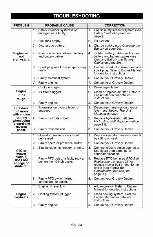
PTO BELT REPLACEMENTRemove (Figure 23)
1. Lower mower deck to the ground.
CAUTION: Use care when releasing idler spring tension. Keep body parts well away from idler when performing this operation.
OA0029Figure 21
1. Spindle2. Tie-Rod
3. Jam Nut
3
2
7-5/8 to 7-3/4 in. (19.4 to 19.7 cm)
2
1
CAUTION: Use care when releasing idler spring tension. Keep body parts well away from idler when performing this operation.
Figure 22 OA0031
5
1
3 24
1. Idler Spring2. Engine Sheave3. Hydrostatic Belt
4. Hydrostatic Transmission Pulley
5. Idler
Figure 23 OA0023
4
3
1
2
Mower Deck Shown Removed For Clarity
1. PTO Belt2. Idler Spring
3. Idler4. Engine Sheave
GB - 22
2. Pull idler (item 3) towards the outside of the unit and remove PTO belt (item 1) from idler (item 3).
3. Remove PTO belt (item 1) from mower deck pulley and engine sheave (item 4).
Install (Figure 23)1. Install PTO belt (item 1) on engine
sheave (item 4) and mower deck pulley.
2. Pull idler (item 3) towards the outside of the unit and place PTO belt (item 1) on idler (item 3).
3. Slowly release idler (item 3) until PTO belt (item 1) rests firmly against idler (item 3).
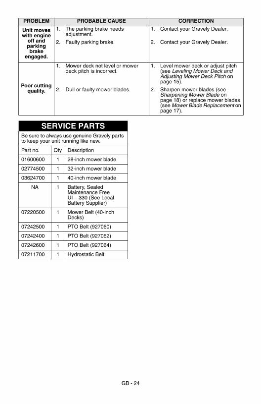
MOWER BELT REPLACEMENT (927064)
Remove (Figure 24)1. Remove mower deck (see Remove and
Install Mower Deck on page 14).2. Remove two belt covers (item 2).
3. Remove idler spring (item 9).4. Remove front bracket (item 4) and clutch
bracket (item 10).5. Remove mower belt (item 8).
Install (Figure 24)1. Install mower belt (item 8) on right pulley
(item 3), idler (item 6), clutch (item 5), and left pulley (item 7).
2. Install clutch bracket (item 10) and front bracket (item 4).
3. Install idler spring (item 9).4. Install two belt covers (item 2).5. Install mower deck (see Remove and
Install Mower Deck on page 14).
Short Term StorageIMPORTANT: NEVER clean unit with high-pressure water or store unit outdoors.Remove all dirt, grease, leaves, etc. Store in a clean dry area.Inspect unit for signs of wear or damage. Ensure all fasteners are properly tightened.
Long Term StorageFollow all instructions under Short Term Storage.Remove and fully charge battery. Store in a clean dry area.Drain fuel from fuel tank.Refer to Engine Manual for the proper engine storage procedures.Touch up all scratched or chipped paint surfaces.
OA0070
4 6
8
2, 3
2, 7
9
5
10
1
Figure 24
1. Mower Deck2. Belt Cover3. Right Pulley4. Front Bracket5. Clutch6. Idler7. Left Pulley8. Mower Belt9. Idler Spring10. Clutch Bracket
CAUTION: Use care when releasing idler spring tension. Keep body parts well away from idler when performing this operation.
STORAGE
GB - 23
TROUBLESHOOTING
PROBLEM PROBABLE CAUSE CORRECTION
Engine will not
crank/start.
1. Safety interlock system is not engaged or is faulty.
1. Check safety interlock system (see Safety Interlock System on page 9).
2. Fuel tank empty. 2. Fill fuel tank.
3. Discharged battery. 3. Charge battery (see Charging the Battery on page 20).
4. Poor connection between battery and battery cables.
4. Tighten battery cables and/or clean battery and battery cables (see Cleaning Battery and Battery Cables on page 20).
5. Spark plug wire loose or spark plug faulty.
5. Connect spark plug wire or replace spark plug. Refer to Engine Manual for detailed instructions.
6. Faulty electrical system. 6. Contact your Gravely Dealer.
7. Faulty engine. 7. Contact your Gravely Dealer.
Engine runs
rough.
1. Choke engaged. 1. Disengage choke.
2. Air filter plugged. 2. Clean or replace air filter. Refer to Engine Manual for detailed instructions.
3. Faulty engine. 3. Contact your Gravely Dealer.
Unit does not move
with engine running
when using forward and
reverse pedal.
1. Transmission bypass lever is engaged.
1. Disengage transmission bypass lever (see Moving The Unit Manually on page 11).
2. Faulty hydrostatic belt. 2. Replace hydrostatic belt (see Hydrostatic Belt Replacement on page 21).
3. Faulty transmission. 3. Contact your Gravely Dealer.
PTO or mower
blade(s) does not
engage or shuts off.
1. Operator presence switch not depressed.
1. Depress operator presence switch by sitting on seat.
2. Faulty operator presence switch. 2. Contact your Gravely Dealer.
3. Electric clutch connector is loose. 3. Connect electric clutch connector. See figure 9 on page 15 for connector location.
4. Faulty PTO belt or a faulty mower belt on the 40-inch decks.
4. Replace PTO belt (see PTO Belt Replacement on page 21) or replace mower belt on the 40-inch decks (see Mower Belt Replacement (927064) on page 22).
5. Faulty PTO switch, wires, connectors, or clutch.
5. Contact your Gravely Dealer.
Engine overheats.
1. Engine oil level low. 1. Add engine oil. Refer to Engine Manual for detailed instructions.
2. Cooling system plugged. 2. Clean cooling system. Refer to Engine Manual for detailed instructions.
3. Faulty engine. 3. Contact your Gravely Dealer.
GB - 24
Unit moves with engine
off and parking brake
engaged.
1. The parking brake needs adjustment.
1. Contact your Gravely Dealer.
2. Faulty parking brake. 2. Contact your Gravely Dealer.
Poor cutting quality.
1. Mower deck not level or mower deck pitch is incorrect.
1. Level mower deck or adjust pitch (see Leveling Mower Deck and Adjusting Mower Deck Pitch on page 15).
2. Dull or faulty mower blades. 2. Sharpen mower blades (see Sharpening Mower Blade on page 18) or replace mower blades (see Mower Blade Replacement on page 17).
PROBLEM PROBABLE CAUSE CORRECTION
SERVICE PARTSBe sure to always use genuine Gravely parts to keep your unit running like new.
Part no. Qty Description
01600600 1 28-inch mower blade
02774500 1 32-inch mower blade
03624700 1 40-inch mower blade
NA 1 Battery, Sealed Maintenance Free UI – 330 (See Local Battery Supplier)
07220500 1 Mower Belt (40-inch Decks)
07242500 1 PTO Belt (927060)
07242400 1 PTO Belt (927062)
07242600 1 PTO Belt (927064)
07211700 1 Hydrostatic Belt
GB - 25
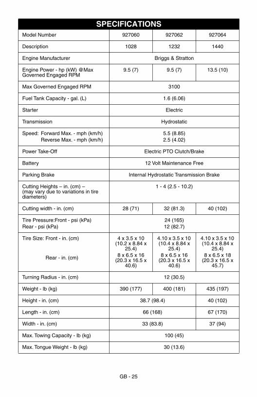
SPECIFICATIONSModel Number 927060 927062 927064
Description 1028 1232 1440
Engine Manufacturer Briggs & Stratton
Engine Power - hp (kW) @Max Governed Engaged RPM
9.5 (7) 9.5 (7) 13.5 (10)
Max Governed Engaged RPM 3100
Fuel Tank Capacity - gal. (L) 1.6 (6.06)
Starter Electric
Transmission Hydrostatic
Speed: Forward Max. - mph (km/h)Reverse Max. - mph (km/h)
5.5 (8.85)2.5 (4.02)
Power Take-Off Electric PTO Clutch/Brake
Battery 12 Volt Maintenance Free
Parking Brake Internal Hydrostatic Transmission Brake
Cutting Heights – in. (cm) – (may vary due to variations in tire diameters)
1 - 4 (2.5 - 10.2)
Cutting width - in. (cm) 28 (71) 32 (81.3) 40 (102)
Tire Pressure:Front - psi (kPa)Rear - psi (kPa)
24 (165)12 (82.7)
Tire Size: Front - in. (cm)
Rear - in. (cm)
4 x 3.5 x 10 (10.2 x 8.84 x
25.4)8 x 6.5 x 16
(20.3 x 16.5 x 40.6)
4.10 x 3.5 x 10 (10.4 x 8.84 x
25.4)8 x 6.5 x 16
(20.3 x 16.5 x 40.6)
4.10 x 3.5 x 10 (10.4 x 8.84 x
25.4)8 x 6.5 x 18
(20.3 x 16.5 x 45.7)
Turning Radius - in. (cm) 12 (30.5)
Weight - lb (kg) 390 (177) 400 (181) 435 (197)
Height - in. (cm) 38.7 (98.4) 40 (102)
Length - in. (cm) 66 (168) 67 (170)
Width - in. (cm) 33 (83.8) 37 (94)
Max. Towing Capacity - lb (kg) 100 (45)
Max. Tongue Weight - lb (kg) 30 (13.6)
GB - 26
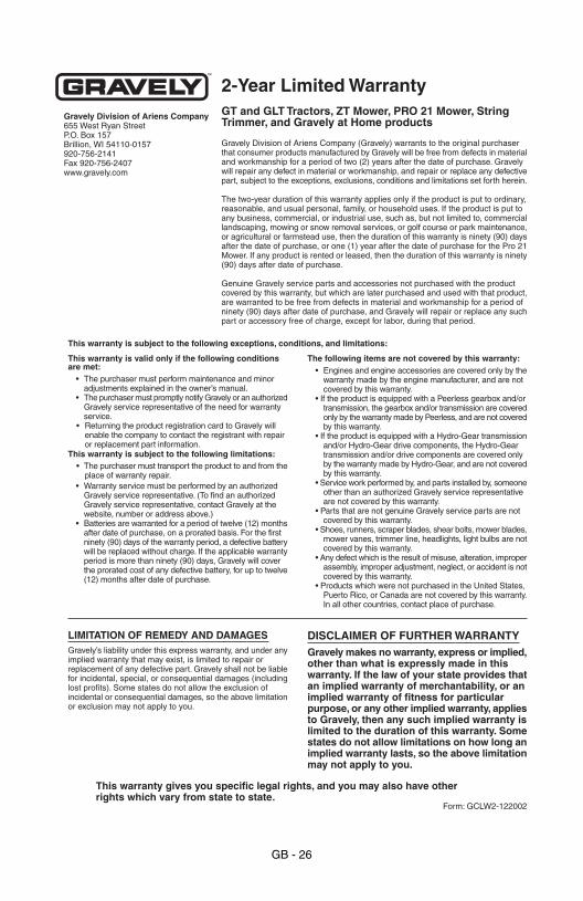
2-Year Limited Warranty
Gravely Division of Ariens Company (Gravely) warrants to the original purchaserthat consumer products manufactured by Gravely will be free from defects in materialand workmanship for a period of two (2) years after the date of purchase. Gravelywill repair any defect in material or workmanship, and repair or replace any defectivepart, subject to the exceptions, exclusions, conditions and limitations set forth herein.
The two-year duration of this warranty applies only if the product is put to ordinary,reasonable, and usual personal, family, or household uses. If the product is put toany business, commercial, or industrial use, such as, but not limited to, commerciallandscaping, mowing or snow removal services, or golf course or park maintenance,or agricultural or farmstead use, then the duration of this warranty is ninety (90) daysafter the date of purchase, or one (1) year after the date of purchase for the Pro 21Mower. If any product is rented or leased, then the duration of this warranty is ninety(90) days after date of purchase.
Genuine Gravely service parts and accessories not purchased with the productcovered by this warranty, but which are later purchased and used with that product,are warranted to be free from defects in material and workmanship for a period ofninety (90) days after date of purchase, and Gravely will repair or replace any suchpart or accessory free of charge, except for labor, during that period.
Gravely Division of Ariens Company655 West Ryan StreetP.O. Box 157Brillion, WI 54110-0157920-756-2141Fax 920-756-2407www.gravely.com
LIMITATION OF REMEDY AND DAMAGESGravely’s liability under this express warranty, and under anyimplied warranty that may exist, is limited to repair orreplacement of any defective part. Gravely shall not be liablefor incidental, special, or consequential damages (includinglost profits). Some states do not allow the exclusion ofincidental or consequential damages, so the above limitationor exclusion may not apply to you.
DISCLAIMER OF FURTHER WARRANTYGravely makes no warranty, express or implied,other than what is expressly made in thiswarranty. If the law of your state provides thatan implied warranty of merchantability, or animplied warranty of fitness for particularpurpose, or any other implied warranty, appliesto Gravely, then any such implied warranty islimited to the duration of this warranty. Somestates do not allow limitations on how long animplied warranty lasts, so the above limitationmay not apply to you.
This warranty is valid only if the following conditionsare met:
• The purchaser must perform maintenance and minoradjustments explained in the owner’s manual.
• The purchaser must promptly notify Gravely or an authorizedGravely service representative of the need for warrantyservice.
• Returning the product registration card to Gravely willenable the company to contact the registrant with repairor replacement part information.
This warranty is subject to the following limitations:• The purchaser must transport the product to and from the
place of warranty repair.• Warranty service must be performed by an authorized
Gravely service representative. (To find an authorizedGravely service representative, contact Gravely at thewebsite, number or address above.)
• Batteries are warranted for a period of twelve (12) monthsafter date of purchase, on a prorated basis. For the firstninety (90) days of the warranty period, a defective batterywill be replaced without charge. If the applicable warrantyperiod is more than ninety (90) days, Gravely will coverthe prorated cost of any defective battery, for up to twelve(12) months after date of purchase.
The following items are not covered by this warranty:• Engines and engine accessories are covered only by the
warranty made by the engine manufacturer, and are notcovered by this warranty.
• If the product is equipped with a Peerless gearbox and/ortransmission, the gearbox and/or transmission are coveredonly by the warranty made by Peerless, and are not coveredby this warranty.
• If the product is equipped with a Hydro-Gear transmissionand/or Hydro-Gear drive components, the Hydro-Geartransmission and/or drive components are covered onlyby the warranty made by Hydro-Gear, and are not coveredby this warranty.
• Service work performed by, and parts installed by, someoneother than an authorized Gravely service representativeare not covered by this warranty.
• Parts that are not genuine Gravely service parts are notcovered by this warranty.
• Shoes, runners, scraper blades, shear bolts, mower blades,mower vanes, trimmer line, headlights, light bulbs are notcovered by this warranty.
• Any defect which is the result of misuse, alteration, improperassembly, improper adjustment, neglect, or accident is notcovered by this warranty.
• Products which were not purchased in the United States,Puerto Rico, or Canada are not covered by this warranty.In all other countries, contact place of purchase.
Form: GCLW2-122002
This warranty is subject to the following exceptions, conditions, and limitations:
This warranty gives you specific legal rights, and you may also have otherrights which vary from state to state.
GT and GLT Tractors, ZT Mower, PRO 21 Mower, StringTrimmer, and Gravely at Home products

GRAVELY’A Division of Ariens Company655 West Ryan StreetP.O. Box 157Brillion, WI 54110-0157920-756-2141Fax 920-756-2407www.gravely.com