Embed Size (px)
Citation preview
1
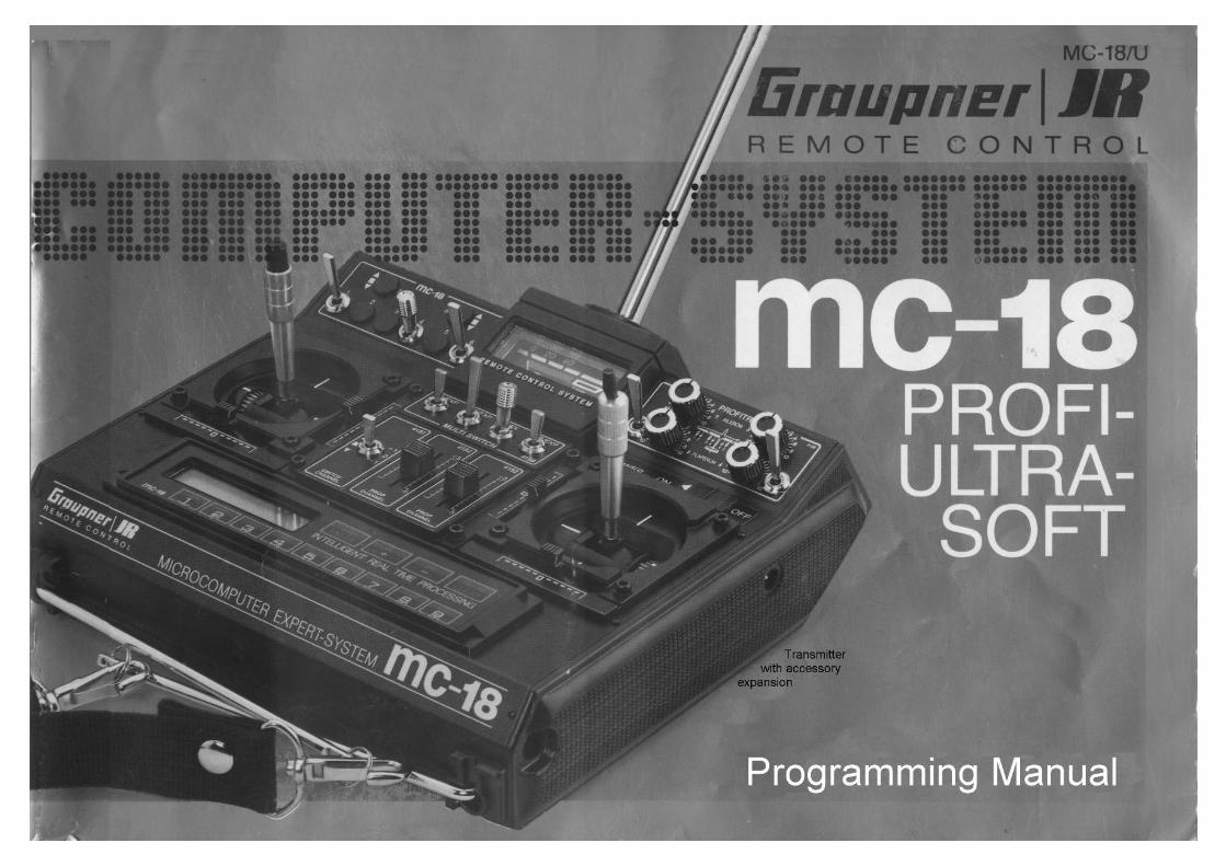
PROFI-ULTRASOFT-MODULE 256k
2
The Graupner PROFI-ULTRASOFT-Module 256k offers the modeller practically all currently imaginable functions for the operation of the most diverse types of sailplanes and powered models, including such complex ones as helicopters. The programs have been developed on the basis of practical experience, in close cooperation with renowned model flyers and, as a result leave barely anything to be desired even for, and in, hard contest environments. The clear, logical design of the various functions, however, enables even the less experienced model flyer to take advantage of these programs in everyday flying conditions and operation.
The complexity of the program and their extreme specialisation on specific model types require separating this programming manual into three sections: a general section which concerns all model types in like manner, another section for fixed-wing power models and sailplane models and a third one for helicopter models. Power models and sailplanes are named fixed-wing models here, to distinguish them from helicopter models.
Fixed-wing model and helicopter sections are arranged in two parts each: the detailed description of the options, which may be called under their specific code numbers, plus a compilation of programming examples which can be used as they are presented here or modified to suit one’s own application requirements.
The numbering of the options has been chosen to suit in-house technical deliberation. Their description, however, follows the sequential order in which they’ll normally be called when performing the setting-up process of a new model.
The high flexibility of adaptability to individual requirements or demands of the operator necessitate the provision of specific allocations before calling and setting up the options depending on them. Thus the possibility of free allocation of the FUAL RATE switches necessitates – for example – the determination of this allocation, before the DUAL RATE values can be adjusted. The same holds true, in similar manner, for other options, in particular those of the helicopter programs.
The beginner and less experienced model flyer will be advised to study and use the programming examples, as practically usable – adjustments can then be made in the shortest possible time, with the essential operational steps being learned at the same time. This applies to the helicopter gyro in particular, which is enabled to adjust a sensible selection of the extensive offering of the helicopter options, and to learn to use them in the process. However, the experienced R/C pilot will benefit as well in studying the programming examples thoroughly and practising the described adjustments, thereby getting familiar with the operation and handling of the transmitter.
In order to spare the user cross-referencing and the bothersome turning of pages from one section to another, both the fixed-wing and helicopter sections contain descriptions of ALL available options, irrespective of whether descriptions have been published previously. This part of the text may appear several times in this manual, as this will help simplify the use of the
MICRO COMPUTER EXPERT SYSTEM MC-18.
Note: All functions of the PROFI-ULTRASOFT-MODUL are compatible with any of the MC-18 transmitters. With transmitters up to the ’88 series only seven models can be stored without back-up copy, however, Conversion from 7 to 30 models storage capacity can be performed by the Graupner Service.
Contents
3
General Section 4 – 7
Codes of the PROFI-ULTRASOFT-MODULE 4 General Information 5 Selection of Model Type 6 – 7 Mode of Operation – Code Menu 7 Analogue Adjustment of Values 7
Fixed-wing model section 8 – 56
Control Connections, Receiver Outlets 8 – 9 Model Type Block Diagrams 10 – 16 Code Chart – Model Types 1 – 5 17 Description of Options – Model Types 1 – 5 18 – 35 Code Chart – F3B Models - Types 6 – 7 36 Description of Options – F3B Models 38 – 43
Fixed-wing Programming Examples
I. Basic Settings 1. Preparations 44 2. Executing a Reset 44 – 45 3. Selection of Model Memory 45 4. Input Name of Model 45 5. Allocation of Control Sticks 46 6. Determining the Type of Model 46 – 47 7. Determining the Idle Trim 47 8. Copying the Settings 48 9. Determining the Modulation Mode 48 – 49
10. Adjusting the Direction of Servo Travel 49 11. Adjusting Servo Throw 50 – 51
II. Supplementary Adjustments 1. Limiting Servo Throw 52 2. Coordination of Throttle Characteristics 52 – 53 3. Storage of Trim Data 35
III. Examples of Copying Single Model Memory 54 All Models Memory 55 Internal Copying 56
Helicopter Section 57 – 118
Receiver Outlets 57 Control Connections 58 Code Chart – Helicopter – Type 8 59 Description of Options – Helicopter Type 8 60 – 87 Description of Options – Helicopter Type 9 87
Helicopter Programming Examples
I. Basic Settings 1. Preparations 88 2. Executing a Reset 88 – 89 3. Selection of Model Memory 89 4. Input Name of Model 89 5. Allocation of Control Sticks 90 6. Determining the Type of Model 90 – 91 7. Direction of Throttle / Pitch Control Stick 91 8. Allocation of Switches 92 9. Copying the Settings 92 – 93
10. Determining the Modulation Mode 93 11. Type of Swashplate 94 12. Direction of Torque Compensation 94 – 95 13. Switching Activation of Auto-rotation 95 14. Adjusting Servo & Rotor Mixer Direction 96 – 97 15. Pitch Adjustments 97 – 99 16. Adjusting Torque Compensation 99 17. Adjusting Carburettor Actuation 100 – 101
II. Upgrading for Advanced Pilots 1. Throttle Preset 102
a. By Slider Control 102 – 103 b. By Switch 103 c. By Switch and Slider Control 103
2. Complementing Auto-Rotation Settings 104 a. Maximum Pitch 104 – 105 b. Minimum Pitch 105 c. Tail Rotor Centre Position in Auto-Rot’n 106
3. Compensating for Tail Rotor Load 106 – 107
III. Further Upgrading for Expert Pilots 1. PROFITRIM Module 108
a. Test Flying with PROFITRIM 108 b. PROFITRIM for Competition Use 109
2. Changeover from Hover to Aerobatics 110 a. Normal Adjustments for Aerobatics 110 b. Alternative Adjustments for Hover 111 – 115
3. Changeover to Auto-Rotation 116 4. Flare Compensation 117 – 118
Appendix Changes from the MULTISOFT-Module 118 – 119
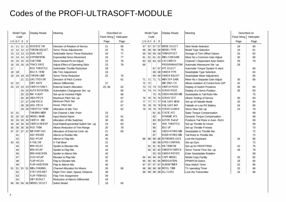
Codes of the PROFI-ULTRASOFT-MODULE
4
Model Type Display Reads Meaning Described on Code Fixed-Wing Helicopter
1-5 6,7 8 9 Page Page
11 11 11 11 REVERSE SW Direction of Rotation of Servos 21 65 12 12 12 12 THROW ADJUST Servo Throw Adjustments 22 75 13 13 13 13 DUAL RATE Switchable Servo Throw Reduction 24 77 14 14 14 14 EXPONENTIAL Exponential Servo Movement 24 77 15 15 15 15 SUB TRIM Servo Neutral Po int Adjust 22 76 16 16 16 16 TRACE RATE Adjust Effect of Operating Stick 23 76 17 RED. THROTTLE Switchable Throttle Reduction 28 18 18 IDLE R. TRIM Idle Trim Adjustment 19 19 19 19 19 THROW LIMIT Servo Throw Reduction 22 76 21 21 GAS STICK DR Direction of Pitch Control 61
22 22 DIFF. RATE Aileron Differential 27 23 23 23 23 SWITCH FUNCT. External Switch Allocation 20, 38 62 24 24 AUTO ROTATION Autorotation Changeover Set -up 66 25 25 INV. FLIGHT Set-up for Inverted Flight 66 26 26 HIGH PITCH Maximum Pitch Set -up 67 27 27 LOW PITCH Minimum Pitch Set 67 28 28 HOV. PITCH Hover. Pitch Set 67 29 29 THROTTLE TRIM Allocation of Idle Trim 62
31 31 THR/BRK MIDP Set Channel 1 Mid -Point 23 32 32 32 32 MODEL NAME Input Model Name 19 61 33 33 33 33 SWITCH MIX Allocation of Mix Switches 30 80 34 34 34 34 SWITCH DR/EXP Dual Rate/Exponential Switch Set -up 24 63 35 35 35 35 RED. TRIM Allows Reduction of Trim Range 25 78 37 37 37 37 INP-PORT ASS Allocation of External Contr ols 21 65 41 AILE RUDD Aileron to Rudder Mix 40 42 AILE FLAP Aileron to Flap Mix 40
43 43 V-TAIL SW V-Tail Mixer 21 44 BRK ELEV Spoiler to Elevator Mix 43 45 BRK FLAP Spoiler to Flap Mix 43 46 BRK AILERON Spoiler to Aileron Mix 43 47 ELEV FLAP Elevator to Flap Mix 42 48 FLAP ELEV Flap to Elevator Mix 42 49 FLAP AILERON Flap to Aileron Mix 40
51 51 51 51 MIXx CHANNEL Channel Allocation for Mixers 30 80 52 STRT-SPD-DIST Flight Trim: Start, Speed, Distance 39 53 FLAP TRIM ASS Flap Trim Assignment 39 54 DIFF REDUCT Reduction of Aileron Differential 43
56 56 56 56 MODEL SELECT Select Model 18 60
Model Type Display Reads Meaning Described on Code Fixed-Wing Helicopter
1-5 6,7 8 9 Page Page
57 57 57 57 MODE SELECT Stick Mode Selection 18 60 58 58 58 58 MODEL TYPE Model Type Selection 19 61 59 59 59 59 TRIM OFFSET Storage of Trim Offset Values 25 82 61 61 61 61 MIXx COM GAIN Mixer No x Common Gain Adjust 30 80 63 63 63 63 CH1-SWITCH Channel 1 Dependant Auto Switch 29 79 66 PROGRAM-AUTOM Automatic Manoeuvre Set -up 28 67 67 ATS SELECT Automatic Torque System S elect 66 68 68 SWASH TYPE Swashplate Type Selection 64 69 69 SWASH ADJUST Swashplate Mixer Adjustment 65
71 71 71 71 MIXx SEP GAIN Mixer No x Separate Gain Adjust 30 80 72 72 MIX ONLY CH Allows Isolation of Control from O/P 32 73 73 73 73 SWITCH POSIT. Display of Switch Positions 36 84 74 74 74 74 SERVO POSIT. Display of a Servo Position 35 83 75 75 SWSH RUDD MIX Swashplate to Tail Rotor Mix 75
76 76 76 76 SERVO TEST Allows Testing of Servos 35 83 77 77 77 77 FAIL SAFE MEM Set-up of Failsafe Mode 33 84 78 78 78 78 FAIL SAFE BAT Failsafe on Low RX Battery 34 85 79 79 79 79 SERVO SLOW-D Servo Slow Set -up 23 78 81 81 STATIC ATS Static Torque Compensation 68 82 DYNAMIC ATS Dynamic Torque Compensation 68 83 83 AUTOR. Rud-of Positions Tail Rotor in Auto -Rot’n 69 84 HOV. THROTTLE Set-up Throttle for Hover 69 85 IDLE UP Set-up Throttle P resets 70 86 SWSH THRO MIX Swashplate to Throttle Mix 72 87 RUDD THRO MIX Tail Rotor to Throttle Mix 72
88 88 88 88 KEYBOARD LOCK Lock the Keyboard 34 86 89 89 GYRO CONTROL Set-up Gyro 72 91 91 91 AN. TRIM SW Set-up for PROFITRIM 42 75 92 92 92 SMOOTH SWITCH Servo Transit Time Set -up 39 78 93 93 SWASH ROTATE Enter Swashplate Rotation 68
94 94 94 94 COPY MODEL Model Copy Facility 26 82 95 95 95 95 MODULATION PPM/PCM Select 18 60 97 97 97 97 ALARM TIMER Stop Watch Timer 32 85 98 98 98 98 INTEG. TIME TX operating Timer 33 86 99 99 99 99 ALL CLOSE Lock the Transmitter 34 86
General Information Applicable to all Model Types
5
The installation of the module is performed as described in the MC-18 programming manual.
IMPORTANT After installation of the module ALL model memories should be cleared. If this is not done, it is possible that fragments of previous programs left in the memory may cause malfunction in conjunction with the PROFI-ULTRASOFT-Module. To this end, after selecting the model No via code 56 ENTER , entering the model number 1…7 (or 1…301), the key CLEAR has to be pressed first instead of just pressing the ENTER , and ENTER is then used to clear the memories. This step should preferably be performed immediately after installation of the module for ALL model memories, one after another.
Therefore input as follows:
ENTER 5 6 ENTER 1 CLEAR ENTER ENTER 5 6 ENTER 2 CLEAR ENTER … ENTER 5 6 ENTER 7 CLEAR ENTER (… ENTER 5 6 ENTER 3 0 CLEAR ENTER )
This procedure needs only to be performed this one time.
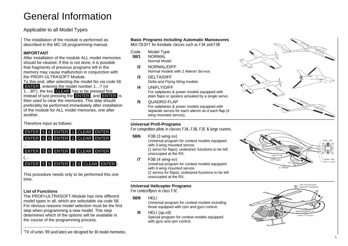
List of Functions The PROFI-ULTRASOFT-Module has nine different model types in all, which are selectable via code 58. For obvious reasons model selection must be the first step when programming a new model. This step determines which of the options will be available in the course of the programming process.
1TX of series ’89 (and later) are designed for 30 model memories.
Basic Programs including Automatic Manoeuvres MULTISOFT for Aerobatic classes such as F3A and F3B
Code Model Type 58/1 NORMAL
Normal Model
/2 NORMAL/DIFF Normal models with 2 Aileron Se rvos
/3 DELTA/DIFF Delta and Flying Wing models
/4 UNIFLY/DIFF For sailplanes & power models equipped with plain flaps or spoilers actuated by a single servo.
/5 QUADRO-FLAP For sailplanes & power models equipped with separate servos for each aileron an d each flap (4 wing mounted servos).
Universal Profi-Programs For competition pilots in classes F3A, F3B, F3E & large soarers.
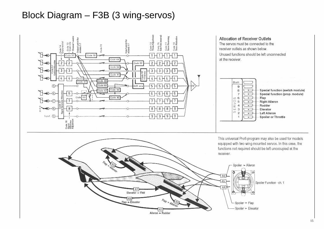
58/6 F3B (3 wing-sv) Universal program for contest models equipped with 3 wing mounted servos. (1 servo for flaps); undesired functions to be left unoccupied at the RX.
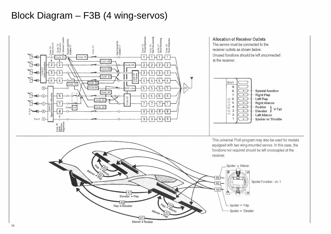
/7 F3B (4 wing-sv) Universal program for contest models equipped with 4 wing mounted servos. (2 servos for flaps); undesired functions to be left unoccupied at the RX.
Universal Helicopter Programs For contest flyers in class F3C
58/8 HELI Universal program for contest models including those equipped with rpm and gyro control.
/9 HELI (sp.ctl) Special program for contest models equipped with gyro and rpm control.
Selection of Model Type
6
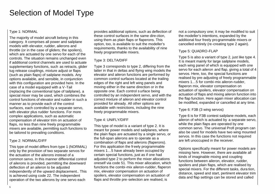
Type 1: NORMAL
The majority of model aircraft belong in this category. It comprises all power and sailplane models with elevator, rudder, ailerons and throttle (or in the case of gliders; the spoilers), which are actuated by one servo for each of the controls. The situation remains unchanged even if additional control channels are used to actuate supplementary functions, such as retracts, glider tug release couplings, mixture adjust or flaps (such as plain flaps) of sailplane models. Any options available, and sensible, in conjunction with this configuration are provided here. In the case of a model equipped with a V -Tail (replacing the conventional type of tailplane), a special mixer may be used, which combines the control functions of elevator and rudder in such a manner as to provide each of the control surfaces, each controlled by a separate servo, with elevator plus rudder functions. For more complex applications, such as automatic compensation of elevator trim on actuation of flaps, no less than nine freely programmable mixers are available, permitting such functions to be tailored to prevailing conditions.
Type 2: NORMAL/DIFF
This type of model differs from type 1 (NORMAL) only by the provision of two separate servos for the actuation of the ailerons instead of a common servo. In this manner differential control of ailerons is provided, permitting the downward deflection of an aileron to be adjusted independently of the upward displacement.. This is achieved using code 22. The independent operation of the two ailerons by one servo each
provides additional options, such as deflection of these control surfaces in the same dire ction, using them as plain flaps or flaperons. This option, too, is available to suit the modeller’s requirements, thanks to the availability of nine freely programmable mixers.
Type 3: DELTA/DIFF
Type 3 corresponds to type 2, differing from the latter in that in deltas and flying wing models the elevator and aileron functions are performed by common control surfaces located at the trailing edges of the right and left wing panels and moving either in the same direction or in the opposite one. Each control surface being controlled by an independent servo, and with the correct mixture of aileron and elevator control provided for already. All other options are available with restrictions, including the nine freely programmable mixers.
Type 4: UNIFLY/DIFF
This type of model is a variant of type 2. It is meant for power models and sailplanes, where the plain flaps are actuated by a single servo, or the full-span ailerons are to operate as a combination of flaps and ailerons (flaperons). For this application the freely programmable mixers 1…5 have already been occupied by certain special functions, just as if one had adjusted type 2 to perform the mixer allocations oneself via code 51. This mixer allocation, which functions the combi-mix aileron-rudder, flaperon mix, elevator compensation on actuation of spoilers, elevator compensation on actuation of flaps and throttle pre-selection are realised, is
not a compulsory one; it may be modified to suit the modeller’s intentions, expanded by the additional four freely programmable mixers or cancelled entirely (re-creating type 2 again).
Type 5: QUADRO-FLAP
Type 5 is also a variant of type 2, just like type 4. It is meant mainly for large sailplane models, each wing panel of which is equipped with one servo for each aileron and flap, giving a total of 4 servos. Here, too, the special functions are realised by pre-adjusting of freely programmable mixers 1…5 for combi-mix aileron-rudder, flaperon mix, elevator compensation on actuation of spoilers, elevator compensation on actuation of flaps and mixing aileron function into the flap function. Here again mixer allocation can be modified, expanded or cancelled at any time.
Type 6: F3B (3 wing servos)
Type 6 is for F3B contest sailplane models, each aileron of which is actuated by a separate servo, while the plain flaps are operated by one common servo. The universal Profi program can also be used for models have two wing mounted servos. In this case the functions not required are left unoccupied in the receiver.
Options specifically meant for power models are missing here. However, there are available all kinds of imaginable mixing and coupling functions between aileron, elevator, rudder, spoilers and plain flaps, which are realised by special mixers. For the different tasks, dura tion, distance, speed and start, pertinent elevator trim data and flap settings can be stored and called
Mode of Operation Analogue Adjustment of Values
7
later on. For other applications seven freely programmable mixers are available.
Type 7: F3B (4 wing servos)
Type 7 corresponds to type 6, with the exc eption that in the case of type 7 the flaps are actuated by a separate servo each, thus providing additional mix options (ailerons -flaps) which are also realised by a special mixer. Here, too, seven freely programmable mixers are available.
The universal Profi program can also be used for models have two wing mounted servos. In this case the functions not required are left unoccupied in the receiver.
Type 8: HELI
Type 8 is a universal helicopter program for practically all helicopters, unless they are not t o be operated exclusively with an RPM regulator which can not be turned off or overridden by the throttle channel. Here one finds all currently imaginable options for helicopters of all types and sizes, both for normal operation and for demanding competition work.
Type 9: HELI (with speed control)
Type 9 is suitable for model helicopters which are exclusively operated with a speed control operated via an auxiliary channel. In this case the compensating functions acting on engine control are missing. Other control functions effect the auxiliary channel, which in turn correspondingly controls the regulator. If a speed control is used, which can be turned off or overridden by normal throttle control, type 8 should be used.
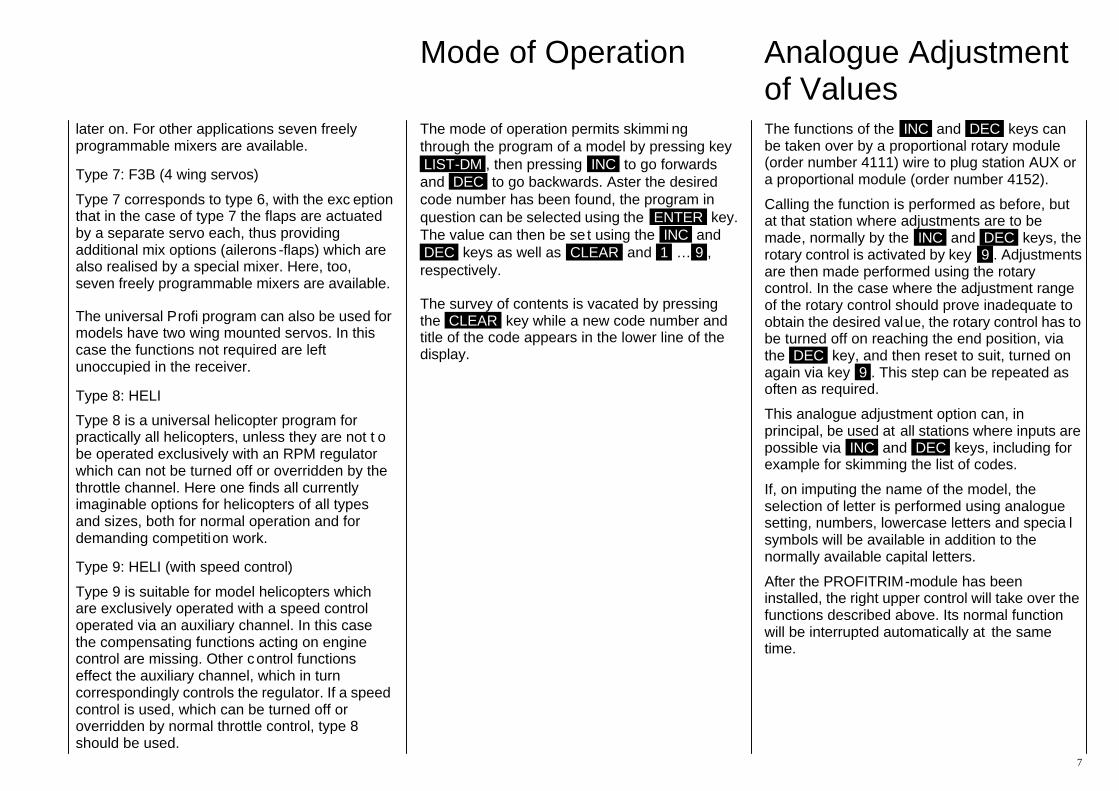
The mode of operation permits skimmi ng through the program of a model by pressing key LIST-DM , then pressing INC to go forwards and DEC to go backwards. Aster the desired code number has been found, the program in question can be selected using the ENTER key. The value can then be se t using the INC and DEC keys as well as CLEAR and 1 … 9 , respectively.
The survey of contents is vacated by pressing the CLEAR key while a new code number and title of the code appears in the lower line of the display.
The functions of the INC and DEC keys can be taken over by a proportional rotary module (order number 4111) wire to plug station AUX or a proportional module (order number 4152).
Calling the function is performed as before, but at that station where adjustments are to be made, normally by the INC and DEC keys, the rotary control is activated by key 9 . Adjustments are then made performed using the rotary control. In the case where the adjustment range of the rotary control should prove inadequate to obtain the desired value, the rotary control has to be turned off on reaching the end position, via the DEC key, and then reset to suit, turned on again via key 9 . This step can be repeated as often as required.
This analogue adjustment option can, in principal, be used at all stations where inputs are possible via INC and DEC keys, including for example for skimming the list of codes.
If, on imputing the name of the model, the selection of letter is performed using analogue setting, numbers, lowercase letters and specia l symbols will be available in addition to the normally available capital letters.
After the PROFITRIM-module has been installed, the right upper control will take over the functions described above. Its normal function will be interrupted automatically at the same time.
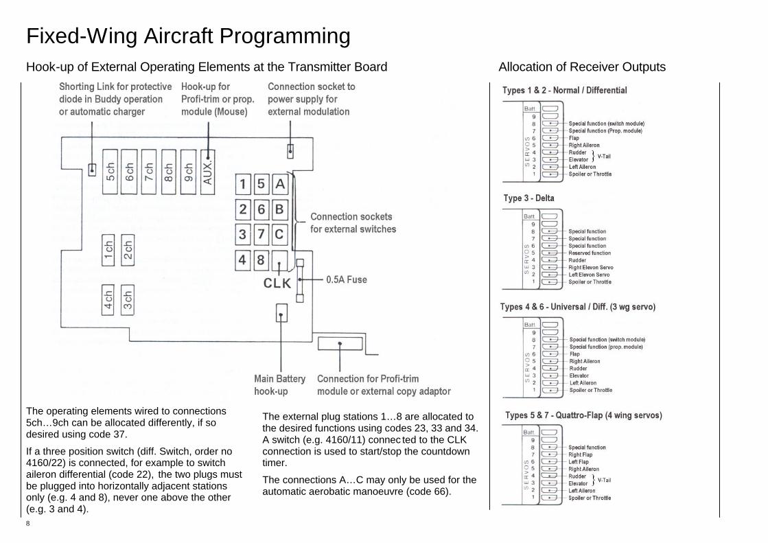
Fixed-Wing Aircraft Programming Hook-up of External Operating Elements at the Transmitter Board Allocation of Receiver Outputs
8
The operating elements wired to connections 5ch…9ch can be allocated differently, if so desired using code 37.
If a three position switch (diff. Switch, order no 4160/22) is connected, for example to switch aileron differential (code 22), the two plugs must be plugged into horizontally adjacent stations only (e.g. 4 and 8), never one above the other (e.g. 3 and 4).
The external plug stations 1…8 are allocated to the desired functions using codes 23, 33 and 34. A switch (e.g. 4160/11) connec ted to the CLK connection is used to start/stop the countdown timer.
The connections A…C may only be used for the automatic aerobatic manoeuvre (code 66).
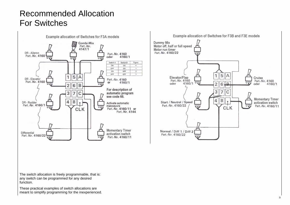
Recommended Allocation For Switches
9
The switch allocation is freely programmable, that is: any switch can be programmed for any desired function.
These practical examples of switch allocations are meant to simplify programming for the inexperienced.
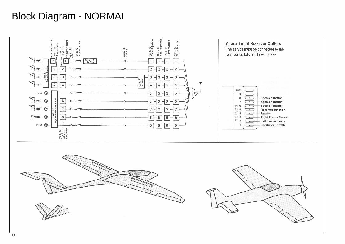
Block Diagram - NORMAL
10
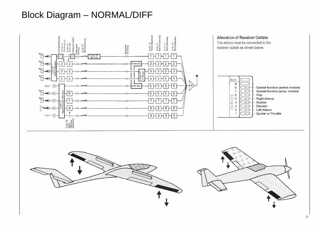
Block Diagram – NORMAL/DIFF
11
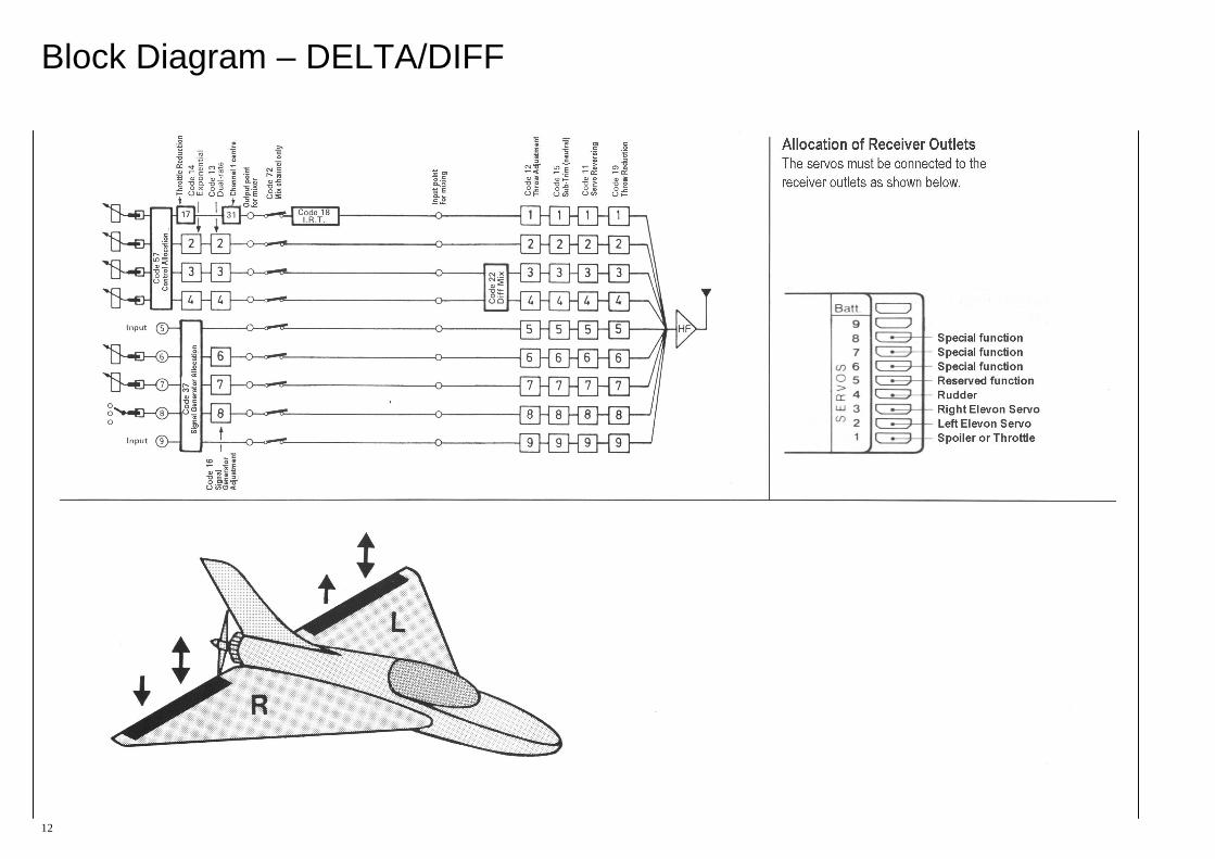
Block Diagram – DELTA/DIFF
12
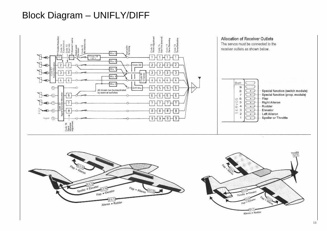
Block Diagram – UNIFLY/DIFF
13

Block Diagram – Quadro-Flap
14
Block Diagram – F3B (3 wing-servos)
15
Block Diagram – F3B (4 wing-servos)
16
Programming Code List (Types 1…5)
17
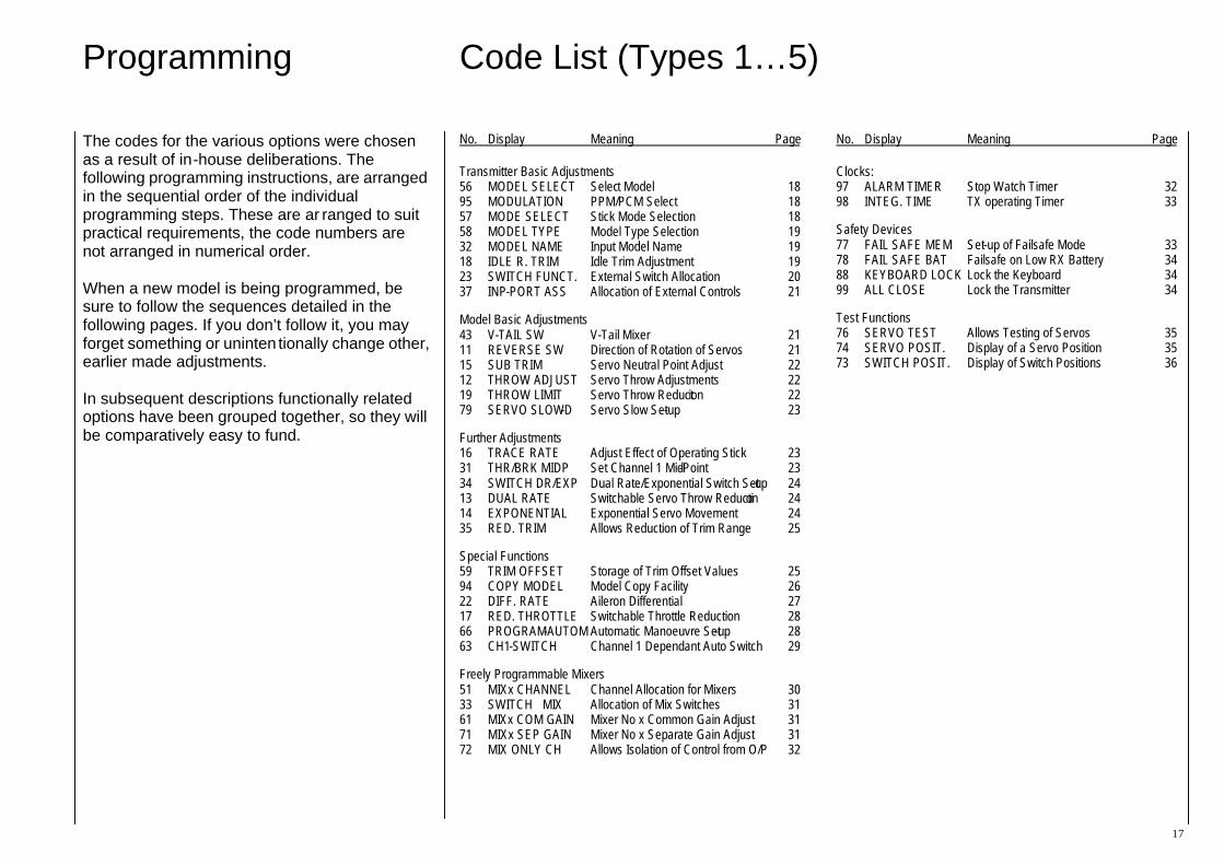
The codes for the various options were chosen as a result of in-house deliberations. The following programming instructions, are arranged in the sequential order of the individual programming steps. These are ar ranged to suit practical requirements, the code numbers are not arranged in numerical order. When a new model is being programmed, be sure to follow the sequences detailed in the following pages. If you don’t follow it, you may forget something or uninten tionally change other, earlier made adjustments. In subsequent descriptions functionally related options have been grouped together, so they will be comparatively easy to fund.
No. Display Meaning Page
Transmitter Basic Adjustments 56 MODEL SELECT Select Model 18 95 MODULATION PPM/PCM Select 18 57 MODE SELECT Stick Mode Selection 18 58 MODEL TYPE Model Type Selection 19 32 MODEL NAME Input Model Name 19 18 IDLE R. TRIM Idle Trim Adjustment 19 23 SWITCH FUNCT. External Switch Allocation 20 37 INP-PORT ASS Allocation of External Controls 21
Model Basic Adjustments 43 V-TAIL SW V-Tail Mixer 21 11 REVERSE SW Direction of Rotation of Servos 21 15 SUB TRIM Servo Neutral Point Adjust 22 12 THROW ADJUST Servo Throw Adjustments 22 19 THROW LIMIT Servo Throw Reduction 22 79 SERVO SLOW-D Servo Slow Set-up 23
Further Adjustments 16 TRACE RATE Adjust Effect of Operating Stick 23 31 THR/BRK MIDP Set Channel 1 Mid-Point 23 34 SWITCH DR/EXP Dual Rate/Exponential Switch Set-up 24 13 DUAL RATE Switchable Servo Throw Reduction 24 14 EXPONENTIAL Exponential Servo Movement 24 35 RED. TRIM Allows Reduction of Trim Range 25
Special Functions 59 TRIM OFFSET Storage of Trim Offset Values 25 94 COPY MODEL Model Copy Facility 26 22 DIFF. RATE Aileron Differential 27 17 RED. THROTTLE Switchable Throttle Reduction 28 66 PROGRAM-AUTOM Automatic Manoeuvre Set-up 28 63 CH1-SWITCH Channel 1 Dependant Auto Switch 29
Freely Programmable Mixers 51 MIXx CHANNEL Channel Allocation for Mixers 30 33 SWITCH MIX Allocation of Mix Switches 31 61 MIXx COM GAIN Mixer No x Common Gain Adjust 31 71 MIXx SEP GAIN Mixer No x Separate Gain Adjust 31 72 MIX ONLY CH Allows Isolation of Control from O/P 32
No. Display Meaning Page
Clocks: 97 ALARM TIMER Stop Watch Timer 32 98 INTEG. TIME TX operating Timer 33
Safety Devices 77 FAIL SAFE MEM Set-up of Failsafe Mode 33 78 FAIL SAFE BAT Failsafe on Low RX Battery 34 88 KEYBOARD LOCK Lock the Keyboard 34 99 ALL CLOSE Lock the Transmitter 34
Test Functions 76 SERVO TEST Allows Testing of Servos 35 74 SERVO POSIT. Display of a Servo Position 35 73 SWITCH POSIT. Display of Switch Positions 36

Code 56 Code 95 Code 57 Model Selection Modulation Control Allocation Selection and Deletion of Models Selection of PPM or PCM Modulation Allocation of Control Functions 1 – 4
18
s e l e c t M O D E L
K E Y 1 - 7 O R + / - The MC-18 transmitter permits the storing the data of seven models and 30 models2, including all trim data. To this end, actual trim data have to be stored into the trim memory via code 59, so the trim sliders of control functions ailerons, elevator and rudder can be moved to the centre position. In this manner finding trim data required for a newly selected model (after a change of model) will be very much simplified, as all you’ve got to remember is that all trim levers will occupy the centre position.
After calling code 56, model selection is performed either directly by entering the model number under which the desired model has been stored, or by skimming through the index of stored models to and fro via keys INC and DEC . In either case the name of the currently selected model will appear in the lower line of the display. You still have the possibility to correct your selection by entering another model or by skimming the index once again.
The selected model will be activated by ENTER . If the CLEAR key is pressed instead of ENTER , complete deletion of the selected model data can be initiated. This process is be performed by the ENTER key, and aborted by any other key.
In case the model selected has been programmed for another kind of modulation than the preceding one, the display message “POWER OFF” indicates that you’ve got to turn the transmitter off and then on again so that the switch from PCM to PPM (or vice versa) can be made.
2 Transmitters are configured for 30 models, starting with series ’89
m c - 1 8 E M O D E L 1
M O D U L A T I O N P P M The MC-18 transmitter permits operation on PPM (Pulse Position Modulation) or PCM (Pulse Code Modulation).
Switch over is provided by code 95, using the INC and DEC keys.
After a change of the modulation mode, the display text will indicate that the transmitter has to be turned off momentarily, so that it can swap over to the changed modulation.
m c - 1 8 E M O D E L 1
M O D E 2 Fundamentally there are four different modes for allocating the control functions ailerons, elevator, rudder and throttle to the two control sticks. Which of them is used depends on the individual preferences of the modeller.
The selection of the desired mode of operation is performed by selection of code 57 via keys 1 ... 4 . Changeover of the internal mechanical spring centring will be required when changing between even and odd mode numbers.
Code 58 Mode 32 Code 18 Model Type Model Name Engine Idle Trim Selection of Model Type Entering Model Names Idle Trim Direction Forward/Backward/Off
19
m c - 1 8 E M O D E L 1
N O R M A L / D I F F
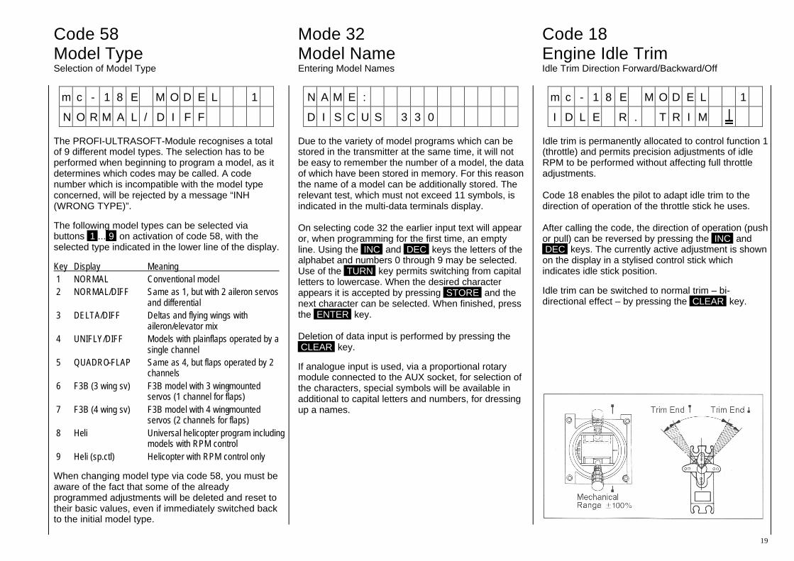
The PROFI-ULTRASOFT-Module recognises a total of 9 different model types. The selection has to be performed when beginning to program a model, as it determines which codes may be called. A code number which is incompatible with the model type concerned, will be rejected by a message “INH (WRONG TYPE)”.
The following model types can be selected via buttons 1 ... 9 on activation of code 58, with the selected type indicated in the lower line of the display.
Key Display Meaning 1 NORMAL Conventional model 2 NORMAL/DIFF Same as 1, but with 2 aileron servos
and differential 3 DELTA/DIFF Deltas and flying wings with
aileron/elevator mix 4 UNIFLY/DIFF Models with plain flaps operated by a
single channel 5 QUADRO-FLAP Same as 4, but flaps operated by 2
channels 6 F3B (3 wing sv) F3B model with 3 wing-mounted
servos (1 channel for flaps) 7 F3B (4 wing sv) F3B model with 4 wing-mounted
servos (2 channels for flaps) 8 Heli Universal helicopter program including
models with RPM control 9 Heli (sp.ctl) Helicopter with RPM control only
When changing model type via code 58, you must be aware of the fact that some of the already programmed adjustments will be deleted and reset to their basic values, even if immediately switched back to the initial model type.
N A M E :
D I S C U S 3 3 0
Due to the variety of model programs which can be stored in the transmitter at the same time, it will not be easy to remember the number of a model, the data of which have been stored in memory. For this reason the name of a model can be additionally stored. The relevant test, which must not exceed 11 symbols, is indicated in the multi-data terminals display. On selecting code 32 the earlier input text will appear or, when programming for the first time, an empty line. Using the INC and DEC keys the letters of the alphabet and numbers 0 through 9 may be selected. Use of the TURN key permits switching from capital letters to lowercase. When the desired character appears it is accepted by pressing STORE and the next character can be selected. When finished, press the ENTER key. Deletion of data input is performed by pressing the CLEAR key.
If analogue input is used, via a proportional rotary module connected to the AUX socket, for selection of the characters, special symbols will be available in additional to capital letters and numbers, for dressing up a names.
m c - 1 8 E M O D E L 1
I D L E R . T R I M
Idle trim is permanently allocated to control function 1 (throttle) and permits precision adjustments of idle RPM to be performed without affecting full throttle adjustments. Code 18 enables the pilot to adapt idle trim to the direction of operation of the throttle stick he uses. After calling the code, the direction of operation (push or pull) can be reversed by pressing the INC and DEC keys. The currently active adjustment is shown on the display in a stylised control stick which indicates idle stick position.
Idle trim can be switched to normal trim – bi-directional effect – by pressing the CLEAR key.
Code 23 Switch Function Allocation of External Switches to Model Types 1 – 5
20
C L K D I 1 D I 2 P R G
N 9 9 N
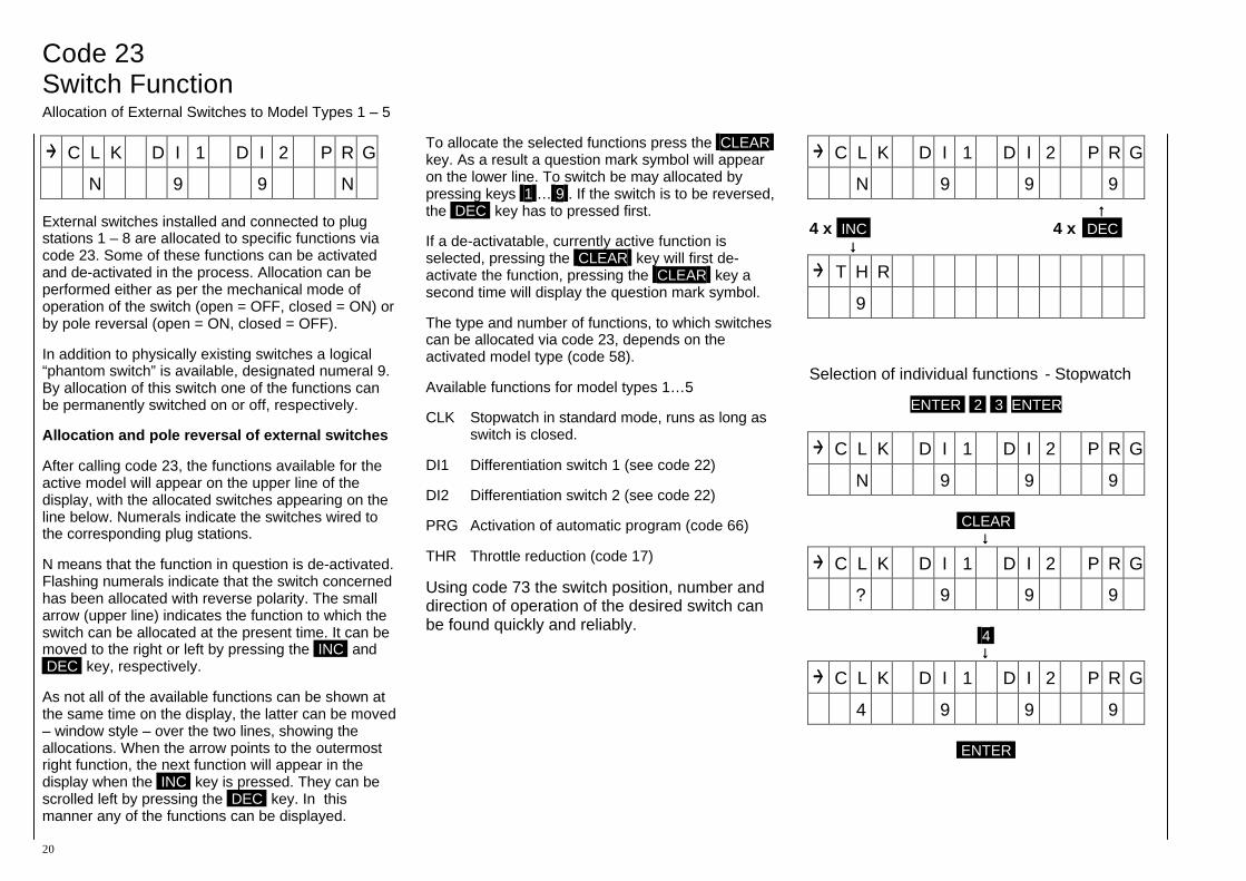
External switches installed and connected to plug stations 1 – 8 are allocated to specific functions via code 23. Some of these functions can be activated and de-activated in the process. Allocation can be performed either as per the mechanical mode of operation of the switch (open = OFF, closed = ON) or by pole reversal (open = ON, closed = OFF).
In addition to physically existing switches a logical “phantom switch” is available, designated numeral 9. By allocation of this switch one of the functions can be permanently switched on or off, respectively.
Allocation and pole reversal of external switches
After calling code 23, the functions available for the active model will appear on the upper line of the display, with the allocated switches appearing on the line below. Numerals indicate the switches wired to the corresponding plug stations.
N means that the function in question is de-activated. Flashing numerals indicate that the switch concerned has been allocated with reverse polarity. The small arrow (upper line) indicates the function to which the switch can be allocated at the present time. It can be moved to the right or left by pressing the INC and DEC key, respectively.
As not all of the available functions can be shown at the same time on the display, the latter can be moved – window style – over the two lines, showing the allocations. When the arrow points to the outermost right function, the next function will appear in the display when the INC key is pressed. They can be scrolled left by pressing the DEC key. In this manner any of the functions can be displayed.
To allocate the selected functions press the CLEAR key. As a result a question mark symbol will appear on the lower line. To switch be may allocated by pressing keys 1 … 9 . If the switch is to be reversed, the DEC key has to pressed first.
If a de-activatable, currently active function is selected, pressing the CLEAR key will first de-activate the function, pressing the CLEAR key a second time will display the question mark symbol.
The type and number of functions, to which switches can be allocated via code 23, depends on the activated model type (code 58).
Available functions for model types 1…5
CLK Stopwatch in standard mode, runs as long as switch is closed.
DI1 Differentiation switch 1 (see code 22)
DI2 Differentiation switch 2 (see code 22)
PRG Activation of automatic program (code 66)
THR Throttle reduction (code 17)
Using code 73 the switch position, number and direction of operation of the desired switch can be found quickly and reliably.
C L K D I 1 D I 2 P R G
N 9 9 9 ↑↑ 4 x INC 4 x DEC ↓↓
T H R
9
Selection of individual functions - Stopwatch
ENTER 2 3 ENTER
C L K D I 1 D I 2 P R G
N 9 9 9
CLEAR ↓↓
C L K D I 1 D I 2 P R G
? 9 9 9 4 ↓↓
C L K D I 1 D I 2 P R G
4 9 9 9
ENTER
Code 37 Code 43 Code 11 Signal Generator Allocation V-Tail Servo Reverse Allocation of Operating Elements Channels 5 – 9 V-Tail Mixer Reversing Direction of Servo Rotation
21
P O R T 5 6 7 8 9
I N P U T 5 6 7 8 9
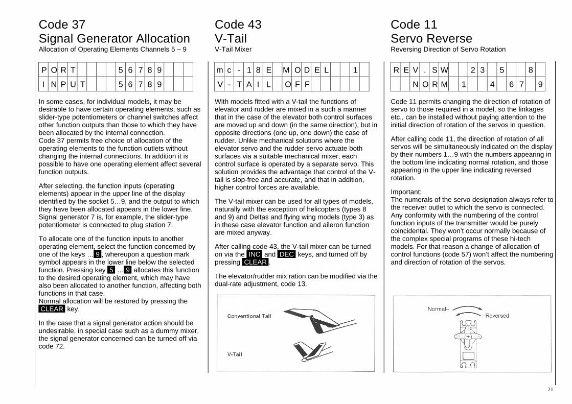
In some cases, for individual models, it may be desirable to have certain operating elements, such as slider-type potentiometers or channel switches affect other function outputs than those to which they have been allocated by the internal connection. Code 37 permits free choice of allocation of the operating elements to the function outlets without changing the internal connections. In addition it is possible to have one operating element affect several function outputs.
After selecting, the function inputs (operating elements) appear in the upper line of the display identified by the socket 5…9, and the output to which they have been allocated appears in the lower line. Signal generator 7 is, for example, the slider-type potentiometer is connected to plug station 7.
To allocate one of the function inputs to another operating element, select the function concerned by one of the keys … 9 , whereupon a question mark symbol appears in the lower line below the selected function. Pressing key 5 … 9 allocates this function to the desired operating element, which may have also been allocated to another function, affecting both functions in that case. Normal allocation will be restored by pressing the CLEAR key.
In the case that a signal generator action should be undesirable, in special case such as a dummy mixer, the signal generator concerned can be turned off via code 72.
m c - 1 8 E M O D E L 1
V - T A I L O F F
With models fitted with a V-tail the functions of elevator and rudder are mixed in a such a manner that in the case of the elevator both control surfaces are moved up and down (in the same direction), but in opposite directions (one up, one down) the case of rudder. Unlike mechanical solutions where the elevator servo and the rudder servo actuate both surfaces via a suitable mechanical mixer, each control surface is operated by a separate servo. This solution provides the advantage that control of the V-tail is slop-free and accurate, and that in addition, higher control forces are available.
The V-tail mixer can be used for all types of models, naturally with the exception of helicopters (types 8 and 9) and Deltas and flying wing models (type 3) as in these case elevator function and aileron function are mixed anyway.
After calling code 43, the V-tail mixer can be turned on via the INC and DEC keys, and turned off by pressing CLEAR .
The elevator/rudder mix ration can be modified via the dual-rate adjustment, code 13.
R E V . S W 2 3 5 8
N O R M 1 4 6 7 9
Code 11 permits changing the direction of rotation of servo to those required in a model, so the linkages etc., can be installed without paying attention to the initial direction of rotation of the servos in question.
After calling code 11, the direction of rotation of all servos will be simultaneously indicated on the display by their numbers 1…9 with the numbers appearing in the bottom line indicating normal rotation, and those appearing in the upper line indicating reversed rotation.
Important: The numerals of the servo designation always refer to the receiver outlet to which the servo is connected. Any conformity with the numbering of the control function inputs of the transmitter would be purely coincidental. They won’t occur normally because of the complex special programs of these hi-tech models. For that reason a change of allocation of control functions (code 57) won’t affect the numbering and direction of rotation of the servos.
Code 15 Code 12 Code 19 Neutral Adjust Servo Travel Adjust Servo Travel Restrict Adjusting the Servo Neutral Position Adjusting Servo Travel Limiting Servo Travel
22
S U B T R I M
p u s h c h k e y 1 - 9
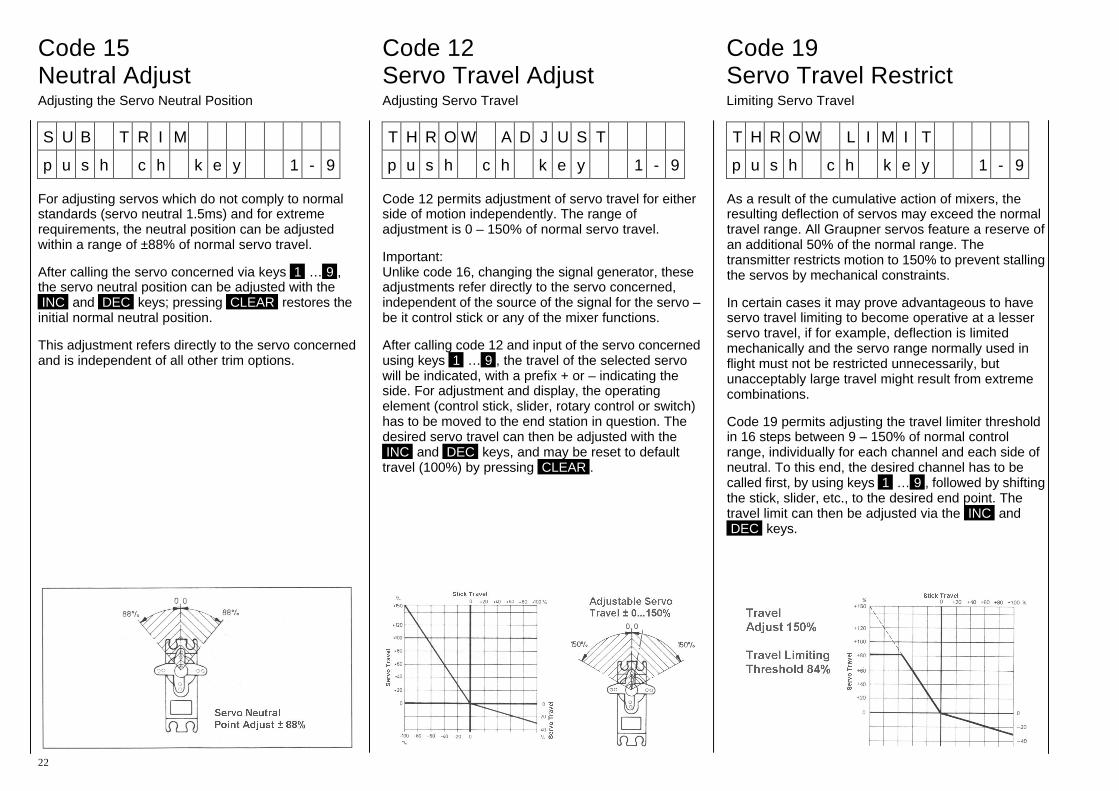
For adjusting servos which do not comply to normal standards (servo neutral 1.5ms) and for extreme requirements, the neutral position can be adjusted within a range of ±88% of normal servo travel.
After calling the servo concerned via keys 1 … 9 , the servo neutral position can be adjusted with the INC and DEC keys; pressing CLEAR restores the initial normal neutral position.
This adjustment refers directly to the servo concerned and is independent of all other trim options.
T H R O W A D J U S T
p u s h c h k e y 1 - 9
Code 12 permits adjustment of servo travel for either side of motion independently. The range of adjustment is 0 – 150% of normal servo travel.
Important: Unlike code 16, changing the signal generator, these adjustments refer directly to the servo concerned, independent of the source of the signal for the servo – be it control stick or any of the mixer functions.
After calling code 12 and input of the servo concerned using keys 1 … 9 , the travel of the selected servo will be indicated, with a prefix + or – indicating the side. For adjustment and display, the operating element (control stick, slider, rotary control or switch) has to be moved to the end station in question. The desired servo travel can then be adjusted with the INC and DEC keys, and may be reset to default travel (100%) by pressing CLEAR .
T H R O W L I M I T
p u s h c h k e y 1 - 9
As a result of the cumulative action of mixers, the resulting deflection of servos may exceed the normal travel range. All Graupner servos feature a reserve of an additional 50% of the normal range. The transmitter restricts motion to 150% to prevent stalling the servos by mechanical constraints.
In certain cases it may prove advantageous to have servo travel limiting to become operative at a lesser servo travel, if for example, deflection is limited mechanically and the servo range normally used in flight must not be restricted unnecessarily, but unacceptably large travel might result from extreme combinations.
Code 19 permits adjusting the travel limiter threshold in 16 steps between 9 – 150% of normal control range, individually for each channel and each side of neutral. To this end, the desired channel has to be called first, by using keys 1 … 9 , followed by shifting the stick, slider, etc., to the desired end point. The travel limit can then be adjusted via the INC and DEC keys.
Code 79 Code 16 Code 31 Servo Slow Down Signal Generator Setting Channel 1 Centre Slowing-Down Transit Time Changing Control Travel Throttle/Spoiler Actuating Curve
23
S L O W D O W N O F F
E N T E R C H T O A C T .
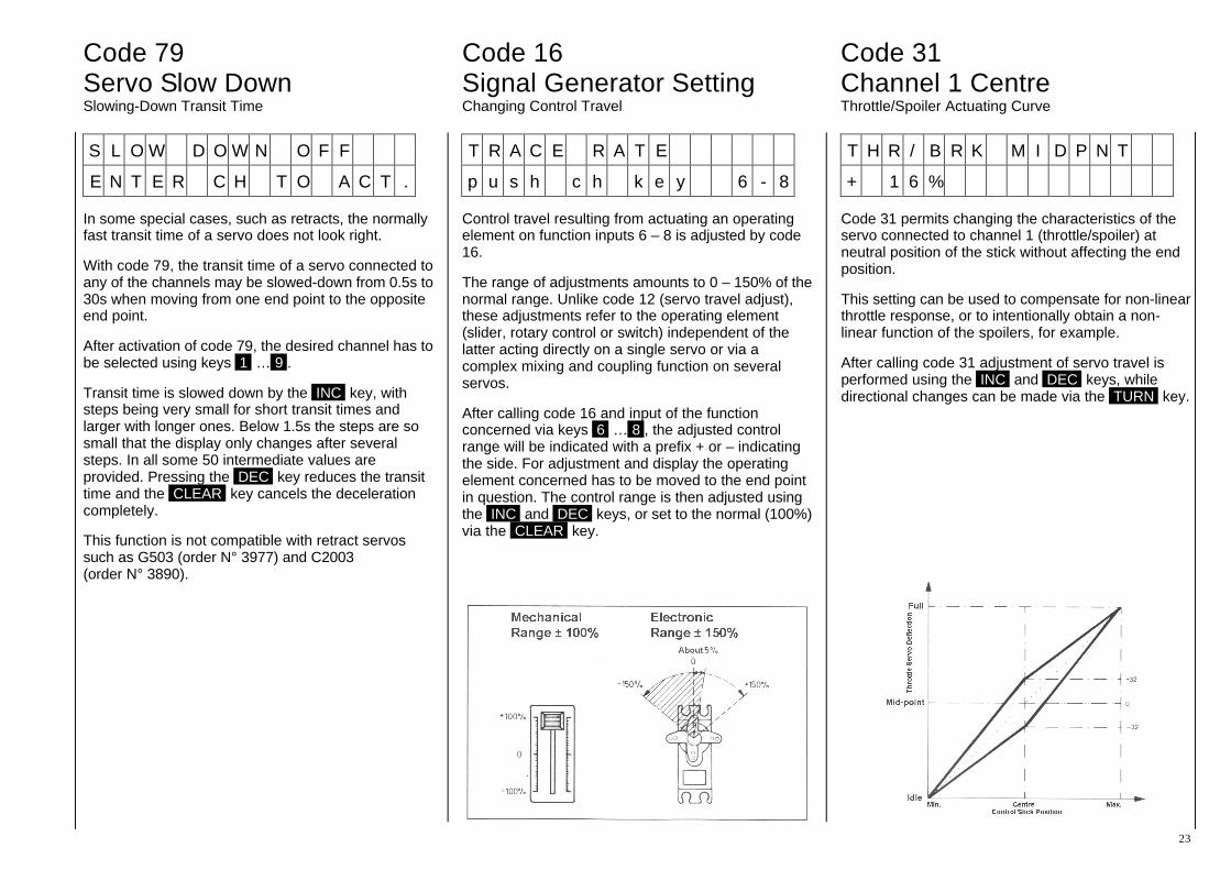
In some special cases, such as retracts, the normally fast transit time of a servo does not look right.
With code 79, the transit time of a servo connected to any of the channels may be slowed-down from 0.5s to 30s when moving from one end point to the opposite end point.
After activation of code 79, the desired channel has to be selected using keys 1 … 9 .
Transit time is slowed down by the INC key, with steps being very small for short transit times and larger with longer ones. Below 1.5s the steps are so small that the display only changes after several steps. In all some 50 intermediate values are provided. Pressing the DEC key reduces the transit time and the CLEAR key cancels the deceleration completely.
This function is not compatible with retract servos such as G503 (order N° 3977) and C2003 (order N° 3890).
T R A C E R A T E
p u s h c h k e y 6 - 8
Control travel resulting from actuating an operating element on function inputs 6 – 8 is adjusted by code 16.
The range of adjustments amounts to 0 – 150% of the normal range. Unlike code 12 (servo travel adjust), these adjustments refer to the operating element (slider, rotary control or switch) independent of the latter acting directly on a single servo or via a complex mixing and coupling function on several servos.
After calling code 16 and input of the function concerned via keys 6 … 8 , the adjusted control range will be indicated with a prefix + or – indicating the side. For adjustment and display the operating element concerned has to be moved to the end point in question. The control range is then adjusted using the INC and DEC keys, or set to the normal (100%) via the CLEAR key.
T H R / B R K M I D P N T
+ 1 6 %
Code 31 permits changing the characteristics of the servo connected to channel 1 (throttle/spoiler) at neutral position of the stick without affecting the end position.
This setting can be used to compensate for non-linear throttle response, or to intentionally obtain a non-linear function of the spoilers, for example.
After calling code 31 adjustment of servo travel is performed using the INC and DEC keys, while directional changes can be made via the TURN key.

Code 34 Code 13 Code 14 DR/EX Switch DUAL RATE EXPONENTIAL Dual Rate / Exponential Switch Allocation Adjustable Servo Throw Reduction Progressive Control Characteristics
24
D R 2 3 4 E X 2 3 4
S W I 9 9 9 9 9 9
The switches for the dual-rate and exponential functions are allocated using code 34. In doing so it is possible to trigger several control functions simultaneously without using multi-function switches.
Due to the possibility of reversing switch functions via the DEC key, dual-rate and exponential can be coupled with ant other function switch.
Allocation and reversing of external switches
After calling the designations of the control functions will appear in the upper line of the display for dual-rate and exponential, with the allocated switches concerned in the lower line. The small arrow in the upper line indicates whether the allocation for dual-rate or exponential is being performed, and it’s position can be changed using the INC and DEC keys.
Allocation of the switches is performed by pressing the key for the input function ( 2 … 4 ) followed by the switch number, if necessary pressing DEC first to reverse the switch polarity.
After all allocations have been made, press ENTER to store the settings.
Using code 73, switch position, the number and orientation of the switches can be found quickly and reliably.
D U A L R A T E
p u s h c h k e y 2 - 4
The dual-rate function permits in-flight switching of control characteristics, with the range of adjustment being variable between 0 – 125% of the normal range for each of the two switch positions. The switched must have been allocated beforehand using code 34.
Dual rate refers directly to the corresponding stick function, independent of whether it affects a single servo or, optionally via complex mixing and coupling functions, several ones.
After calling code 13 the desired control functions can be selected via keys 2 … 4 :
2 = Ailerons 3 = Elevator 4 = Rudder
Adjustments of the control curve are performed using the INC and DEC keys after the switch has been moved to the appropriate position (P0/P1).
E X P O N E N T I A L
p u s h c h k e y 2 - 4
Exponential control permits obtaining sensitive control of a model near the neutral position of the function concerned, whilst maximum travel remains unaffected. The degree of progression can be adjusted from 0 to 100%, with 0 corresponding to normal linear travel.
The three control functions ailerons, elevator and rudder can be switched from linear to progressive control using switches, which have been allocated by code 34 beforehand, or from one progressive adjustment to another progressive one.
These adjustments refer directly to the corresponding stick function, no matter whether it affects a single servo or, optionally via complex mixing and coupling functions, several ones.
After calling code 14 the desired control functions can be selected via keys 2 … 4 :
2 = Ailerons 3 = Elevator 4 = Rudder
Adjustments of the control curve are performed using the INC and DEC keys after the switch has been moved to the appropriate position. (P0/P1)
In some cases linking the two functions of dual-rate and exponential may make sense. This is achieved by using the same switch when allocating the dual-rate and exponential switches using code 34.

Code 35 Code 59 Trim Reduction Trim Data Memory Reducing Trim Range Storing Trim Data
25
T R I M N O R M . 1 4
T R I M R E D . 2 3
When using dual-ate and/or exponential, trim may in some cases, not appear sensitive enough because of the ratchet steps. Code 35 permits reducing the trim action tom 50% independently for each control function.
After calling code 35, the display will indicate the control functions using normal trim in the upper line, and reduced trim in the lower line. Using keys 1 … 4 permits switching the functions between the two options.
1 = Throttle 2 = Ailerons 3 = Elevator 4 = Rudder
T R I M O F F S E T
S T O R E o r C L E A R
Code 59 is used for storing actual trim data. It can be used in addition to display trim data stored in the memory. After calling the display will show the following message.
T R I M O F F S E T
S T O R E o r C L E A R
From here, branching occurs to the functions of “Trim Storage” or “Display of Stored Trim Data”.
a) Trim Storage
To store actual trim data, press the STORE key. As a result, the display will show
S E T T R I M & E N T E R
+ 1 6 - 0 7 + 0 9 - 1 3 Throttle Aileron Elevator Rudder
with the lower line indicating the positions of the trim levers as a deviation from the neutral position. With the aid of the display the trim levers are then shifted to the neutral position, a step which does not change the trim positions of the model. By pressing the ENTER trim data storage process is terminated and the previous in-flight established tri data now corresponds to the mechanical neutral setting of the trim levers.
Important: In normal cases the trim lever for idle trim should not be changed, as the indicated value does not represent a value which has been established in flight, but a random value for the idle trim position. If a larger deviation from normal value has been stored for function 1 (throttle), this will lead to malfunction of the idle trim. When in doubt the stored trim data for function 1 should be displayed and, if necessary, deleted as described below.
b) Display of trim data memory
If the CLEAR key is pressed instead of the ENTER key the stored trim data of each function can be displayed now using keys 1 … 4 and if necessary deleted (returned to 0) by pressing the CLEAR key. The trim values are:
1 = Throttle 2 = Ailerons 3 = Elevator 4 = Rudder
The deletion of trim memories should preferably be performed for all of the functions prior to entering the data for a new model, so the same range will be available for storing trim data in any direction when test-flying that model.

Code 94 Copying Model Copying Functions
26
C O P Y : F R O M M O D E L
K E Y 1 - 7 O R + / -
Code 94 permits copying model data form one model to another one, and also via an external interface of a transmitter to another mc-18 transmitter.
With the aid of a separately available PC adapter, order N° 8181, it is also possible to transfer either individual model adjustments data or the complete contents of the memory of the transmitter (all models) into a personal computer compatible with industrial standards via the serial interface of the latter, saving it there on a disk for possible re-transfer to the transmitter (or some other transmitter).
A special cable, order N° 4180, will be required for the transfer to another mc-18 transmitter, which has to be plugged into the connection socket for the PROFITRIM module of both transmitters.
After activation of code 94, the transmitter expects the input of the model memory of which a copy is to be produced. This is achieved either by input of the model number or by skimming through the list of models using the INC and DEC keys. The selection is then made by pressing the ENTER key. Then the model memory, into which the copy is to be produced, is selected in the same manner. The copying process is triggered by pressing the ENTER key, with all previously stored data being transferred to the model memory, into which the data is copied. If the name of the model the data of which is being copied has been entered, this name will also be transferred to the copy, but with a + symbol added to the last letter of the name to distinguish it from the original.
For safety’s sake, model memories that are active at the moment must not be copied!
When copying from one transmitter to another, or to a personal computer, selection is performed by keys INC and DEC , with “external interface” for source at the receiving transmitter, and as target for the sending transmitter. In addition, the “all-models memory” option is available, which permits transferring all model memories simultaneously. In that case, the options of both units have to be set accordingly. The transfer process should be initiated by the receiving unit via the ENTER key, followed by the sending one.
Copying between two mc-18 transmitters Using the programming interface mc-18/mc-18 (order N° 4180) single model and all models memories can be copied between two mc-18 transmitters. For example, please refer to pages 54/55.
In the case of transmitters with the extended memory (for 30 models), on deletion (code 56) and when copying (code 94) a back-up copy of that memory will be made onto which the copy is transferred or which is being deleted. This permits reversing accidental deletion or overwriting of model adjustments, this back-up copy being copied onto a normal memory station. Just call code 94 as usual and input “from model” memory station 31. For copying examples between two mc-18 transmitters refer to pages 54/55.
Data Exchange to and from Personal Computers Precise instructions are given in the disk included in the programming interface mc-18/PC (order N° 4181).

Code 22 Differential Aileron Differential in Type 2 – 7 Models
27
m c - 1 8 E M O D E L 1
A I L E D I F 0 N O R M
Differentiation of ailerons serves to correct an undesirable effect called “adverse yaw”. With equal throws on ailerons the drag of the lowered aileron is higher than the drag created by the raised one. The resulting moment about the vertical axis acts in opposite direction to the planned direction of flight. If a model tries to turn to starboard (right) under the action of the ailerons, higher drag is generated on the port (left) side, causing the model to bank to starboard, yet yawing left about the vertical axis at the same time. This effect which us much more apparent with sailplanes, with their high aspect ratio wings and resulting longer lever arms as compare to power models, normally has to be compensated for by simultaneous deflection of rudder, which increases drag still more and impairs flight performance.
In the case of differential ailerons the downward movement of an aileron is less than the upward movement of the opposing aileron. This results in the drag being equal on both sides and in the cancellation of the negative jawing moment.
Mechanical solutions usually require permanent adjustments to be made during the assembly of the model, and in the case of high differential ratios may well introduce slop into the control system.. Electronic differential offers great advantages; each of the ailerons is operated by a separate servo, permitting the ailerons servo to be installed in the wing, ensuring slop free and reproducible adjustments even with 2 piece wings.
The ratio of differential can be adjusted as required via the downward deflection without affecting upward deflection permitting complete suppression of downward motion (Split) in extreme cases. In this manner, one can not only cancel the negative yawing motion moment, but even generate a positive one. In this latter case, operation of the ailerons will make the model yaw towards the direction of turn, permitting even large sailplanes to perform smooth turns on ailerons alone, which would not be possible otherwise.
The PROFI-ULTRASOFT-Module permits storing three different differential ratios which can be called up via allocated switches via code 23. Use of a external differential switch, order N° 4160/22, with three positions is recommended. This permits switching between the three differential values, e.g. switch position 0 = 20% differential used for aerobatics to allow precision rolls, switch position 1 = 50% for assisting the model during thermalling, and finally switch position 2 = 100% (split) for performing turns on ailerons alone at the slope.
After input of code 22, the number of the differential memory (0 – 2) and the stored value in % will appear in the lower line of the display, with 0% representing the standard installation (no differential) and 100% the split function. After changing the switch position into the required position, the desired value can be set via the INC and DEC keys. Resetting to the normal setting (0%) is performed by pressing the CLEAR key.
Code 17 Code 66 Throttle Reduction Automatic Program Switchable, Single-Sided Throttle Throw Reduction Automatic Flight Manoeuvre for Type 1 – 5 Models
28
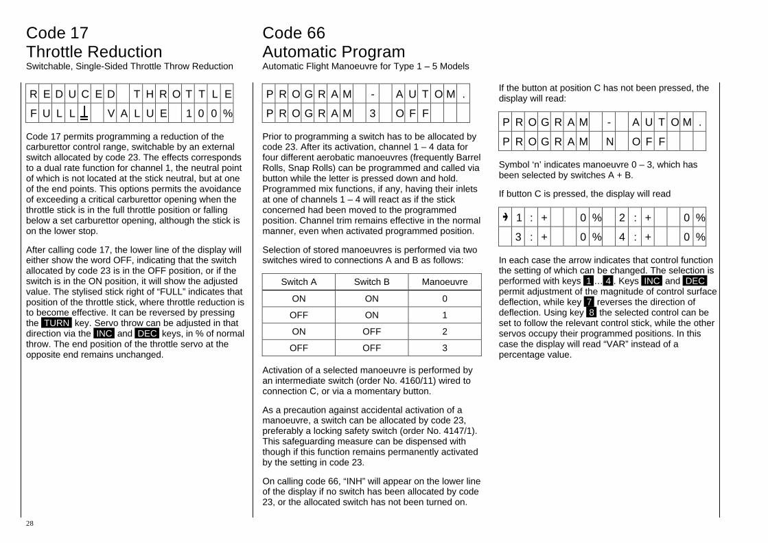
R E D U C E D T H R O T T L E
F U L L V A L U E 1 0 0 %
Code 17 permits programming a reduction of the carburettor control range, switchable by an external switch allocated by code 23. The effects corresponds to a dual rate function for channel 1, the neutral point of which is not located at the stick neutral, but at one of the end points. This options permits the avoidance of exceeding a critical carburettor opening when the throttle stick is in the full throttle position or falling below a set carburettor opening, although the stick is on the lower stop.
After calling code 17, the lower line of the display will either show the word OFF, indicating that the switch allocated by code 23 is in the OFF position, or if the switch is in the ON position, it will show the adjusted value. The stylised stick right of “FULL” indicates that position of the throttle stick, where throttle reduction is to become effective. It can be reversed by pressing the TURN key. Servo throw can be adjusted in that direction via the INC and DEC keys, in % of normal throw. The end position of the throttle servo at the opposite end remains unchanged.
P R O G R A M - A U T O M .
P R O G R A M 3 O F F
Prior to programming a switch has to be allocated by code 23. After its activation, channel 1 – 4 data for four different aerobatic manoeuvres (frequently Barrel Rolls, Snap Rolls) can be programmed and called via button while the letter is pressed down and hold. Programmed mix functions, if any, having their inlets at one of channels 1 – 4 will react as if the stick concerned had been moved to the programmed position. Channel trim remains effective in the normal manner, even when activated programmed position.
Selection of stored manoeuvres is performed via two switches wired to connections A and B as follows:
Switch A Switch B Manoeuvre
ON ON 0
OFF ON 1
ON OFF 2
OFF OFF 3
Activation of a selected manoeuvre is performed by an intermediate switch (order No. 4160/11) wired to connection C, or via a momentary button.
As a precaution against accidental activation of a manoeuvre, a switch can be allocated by code 23, preferably a locking safety switch (order No. 4147/1). This safeguarding measure can be dispensed with though if this function remains permanently activated by the setting in code 23.
On calling code 66, “INH” will appear on the lower line of the display if no switch has been allocated by code 23, or the allocated switch has not been turned on.
If the button at position C has not been pressed, the display will read:
P R O G R A M - A U T O M .
P R O G R A M N O F F
Symbol ‘n’ indicates manoeuvre 0 – 3, which has been selected by switches A + B.
If button C is pressed, the display will read
1 : + 0 % 2 : + 0 %
3 : + 0 % 4 : + 0 %
In each case the arrow indicates that control function the setting of which can be changed. The selection is performed with keys 1 … 4 . Keys INC and DEC permit adjustment of the magnitude of control surface deflection, while key 7 reverses the direction of deflection. Using key 8 the selected control can be set to follow the relevant control stick, while the other servos occupy their programmed positions. In this case the display will read “VAR” instead of a percentage value.

Code 63 Channel 1 Switch Automatic Channel 1 Dependent Switch (Throttle/Spoiler)
29
C H 1 - S W I T C H = ?
For special functions it is desirable not to perform switching by an external switch, but automatically via the channel 1 stick (throttle and spoiler), whereby exceeding a critical stick position provides switch position ON, while falling below provides switch position 0, or vice versa.
The threshold point can be placed anywhere along the stick travel and the modeller can decide whether the upper or lower portion is to activate switch position to the ON state. The automatic switch is allocated to one of the external switch connectors (1…8) whereby it is unrestrictedly included into the free programmability of the external switches via codes 23, 33 and 34.
If a normal switch is also wired to this connection, the two switches (e.g. the external switch and the automatic one) will be wired in parallel. With reversal of polarity being possible with either type of switch, logical links between the two of them can be realised.
“AND“ Link Both switches must be closed so the connected function(s) can be performed.
“OR” Link The connected function(s) is (are) performed when either switch is closed.
As a result the external switch may be used to perform automatic switch over by the stick. By including the automatic switch into a free allocation of external switch any combination of functions can be switched in dependency of the control stick position. So, by turning on the correspondingly programmed misers, flaps can be lowered when throttling the engine and the elevator re-trimmed (Auto-Landing), or dual-rates may be switched to increase control surface throw in the landing approach at reduced speed. Pilots of electric flight models can turn the timer on and off via the automatic switch for checking motor run synchronously with the main drive motor.
Programming:
After calling, via code 63, the transmitter, as in the above display, indicates it is waiting for the input of the external switch connection (1…8), to which the automatic switch is to be allocated. After the connection number (e.g. “6”) has been input the display will read like:
C H 1 - S W I T C H = 6
= C H 1 S = P 6 =
Here the interaction of the automatic switch and a possibly connected external switch is shown. The stylised control stick at the left of the lower line indicates the direction of deflection of the throttle/spoiler stick with the switch in the open position. Direction can be reversed by hitting the TURN key.
The switch state (open or closed) of the channel 1 switch is indicated in the centre of the lower line. By moving the stick the function can be checked and the threshold point be adjusted. To do this the stick is moved to the position at which switching is to occur, then press the STORE key.
The right end of the lower line displays the switch state of a switch wired to its allocated external switch connection.
The interaction of the external switch and automatic channel 1 switch is displayed at the right end of the upper line of the display.
The allocation of the channel 1 switch is cancelled by pressing the CLEAR key.
Code 51, 33, 61 and 71 Free Program Mixer Programming Mixers and Dummy Mixers
30
In addition to the available mix and coupling functions, all model programs provide a number of freely programmable mixers. In the case of type 1 - 3 models nine mixers are at the disposal of the user, types 4 and 5 have four mixers available, for F3B types 6 and 7 a total of seven, and for the helicopter types 8 and 9 there are four mixers available.
The mixers link an input signal to an outlet signal, with allocation performed by code 51. As any optional control function can be fed as an inlet signal, the outlet signal affects any desired control channel, not a control function. Distinguishing between these two terms is of utmost importance. Control function refers to the outlet signal of an operating element, that is a stick with or without trim, slider, rotary control or a channel switch, which in the course of the ensuing action passes through all the mix and coupling functions of the model program. A control channel is the outlet signal for a specific receiver connection, which until it arrives at the servo can only be affected by throw adjust, neutral point adjust, throw reduction or control surface reversing.
Mixers may also be switched in series for special applications, which is say that in addition to the control function proper all other preceding mixers can also be used as inlet functions. All F3B mixers (see F3B programs) and all freely programmable mixers with a lower number are considered as preceding mixers.
To give you an idea, imagine that instead of a control function (see above) the outlet signal of a control channel is used as the input function of the mixer before it passes through throw adjust, neutral point adjust, throw reduction or servo reversing.
Each of the freely programmable mixers can be turned on and off by one of the switches allocated using code 33.
Vital parameters of the mixers are the mix quotas which determine how strongly the inlet signal affects the control channel wired to the outlet of the mixer. They also set the direction of the mixed signal and the neutral point of the mixer, that is the point on the control characteristic curve of the inlet signal where the mixer does not affect the control channel wired to the outlet (normally this will be the neutral point of the control stick).
In the case of freely programmable mixers, these parameters can be adjusted over a wide range. The neutral point can be shifted to any desired point of the control throw of the operating element wired to the inlet (the distance from neutral point is called the OFFSET). The mixing ratios can also be adjusted in both directions above and below the neutral point, either in symmetrical (code 61) or asymmetrical (code 71) fashion. The mix direction can also be set for both sides using codes 61 and 71 by setting the values as + or -.
As a single control function can serve as inlet for an optional number of mixers, and any number of mixers may affect a control channel, the freely programmable mixers permit achievement of special, highly complex, applications.
DUMMY Mixer: A so called dummy function may also be allocated as an inlet signal, that is a control function that is not available as a true operating element, but provides a consistent control signal. In this manner it is possible to make use of a control channel as an operating element by allocating a dummy mixer and having the outlet of the mixer affect the channel concerned. Throw of the switch is then adjusted by the mix quota and mix direction of the dummy mixer. A dummy mixer also permits mixing an additional constant trim signal dependent on a switch allocated by code 33.
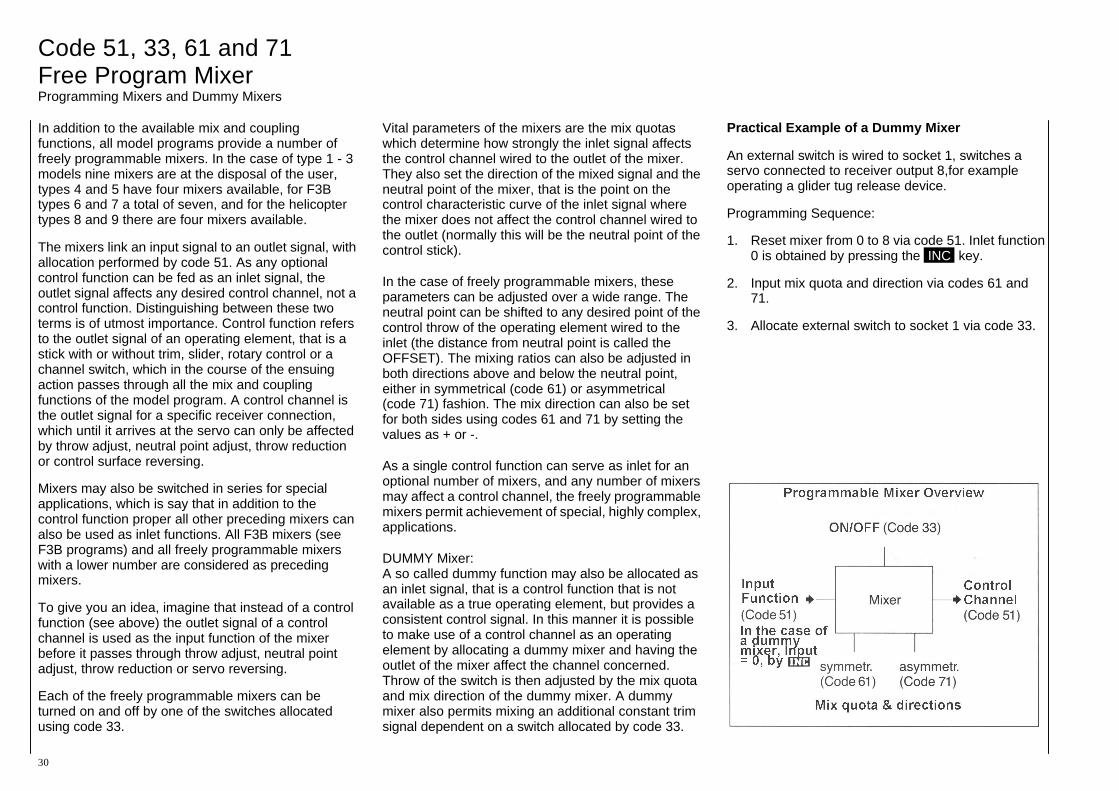
Practical Example of a Dummy Mixer
An external switch is wired to socket 1, switches a servo connected to receiver output 8,for example operating a glider tug release device.
Programming Sequence:
1. Reset mixer from 0 to 8 via code 51. Inlet function 0 is obtained by pressing the INC key.
2. Input mix quota and direction via codes 61 and 71.
3. Allocate external switch to socket 1 via code 33.
31
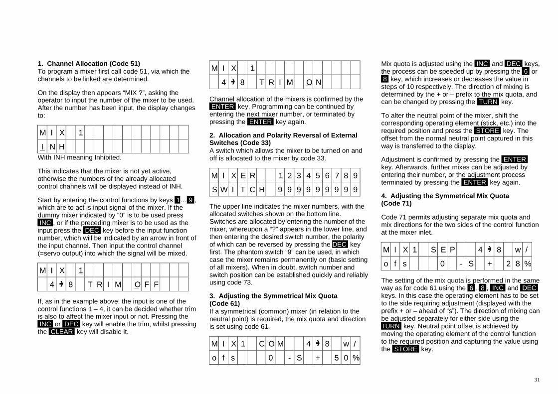
1. Channel Allocation (Code 51) To program a mixer first call code 51, via which the channels to be linked are determined.
On the display then appears “MIX ?”, asking the operator to input the number of the mixer to be used. After the number has been input, the display changes to:
M I X 1
I N H With INH meaning Inhibited.
This indicates that the mixer is not yet active, otherwise the numbers of the already allocated control channels will be displayed instead of INH.
Start by entering the control functions by keys 1… 9 , which are to act is input signal of the mixer. If the dummy mixer indicated by “0” is to be used press INC , or if the preceding mixer is to be used as the input press the DEC key before the input function number, which will be indicated by an arrow in front of the input channel. Then input the control channel (=servo output) into which the signal will be mixed.
M I X 1
4 8 T R I M O F F
If, as in the example above, the input is one of the control functions 1 – 4, it can be decided whether trim is also to affect the mixer input or not. Pressing the INC or DEC key will enable the trim, whilst pressing the CLEAR key will disable it.
M I X 1
4 8 T R I M O N
Channel allocation of the mixers is confirmed by the ENTER key. Programming can be continued by entering the next mixer number, or terminated by pressing the ENTER key again.
2. Allocation and Polarity Reversal of External Switches (Code 33) A switch which allows the mixer to be turned on and off is allocated to the mixer by code 33.
M I X E R 1 2 3 4 5 6 7 8 9
S W I T C H 9 9 9 9 9 9 9 9 9
The upper line indicates the mixer numbers, with the allocated switches shown on the bottom line. Switches are allocated by entering the number of the mixer, whereupon a “?” appears in the lower line, and then entering the desired switch number, the polarity of which can be reversed by pressing the DEC key first. The phantom switch “9” can be used, in which case the mixer remains permanently on (basic setting of all mixers). When in doubt, switch number and switch position can be established quickly and reliably using code 73.
3. Adjusting the Symmetrical Mix Quota (Code 61) If a symmetrical (common) mixer (in relation to the neutral point) is required, the mix quota and direction is set using code 61.
M I X 1 C O M 4 8 w /
o f s 0 - S + 5 0 %
Mix quota is adjusted using the INC and DEC keys, the process can be speeded up by pressing the 6 or 8 key, which increases or decreases the value in steps of 10 respectively. The direction of mixing is determined by the + or – prefix to the mix quota, and can be changed by pressing the TURN key.
To alter the neutral point of the mixer, shift the corresponding operating element (stick, etc.) into the required position and press the STORE key. The offset from the normal neutral point captured in this way is transferred to the display.
Adjustment is confirmed by pressing the ENTER key. Afterwards, further mixes can be adjusted by entering their number, or the adjustment process terminated by pressing the ENTER key again.
4. Adjusting the Symmetrical Mix Quota (Code 71)
Code 71 permits adjusting separate mix quota and mix directions for the two sides of the control function at the mixer inlet.
M I X 1 S E P 4 8 w /
o f s 0 - S + 2 8 %
The setting of the mix quota is performed in the same way as for code 61 using the 6 , 8 , INC and DEC keys. In this case the operating element has to be set to the side requiring adjustment (displayed with the prefix + or – ahead of “s”). The direction of mixing can be adjusted separately for either side using the TURN key. Neutral point offset is achieved by moving the operating element of the control function to the required position and capturing the value using the STORE key.
Code 72 ALARM TIMER and Code 97 MIX-only Channel Stopwatch Stopwatch Mix-only Channel Set-up Stopwatch
32
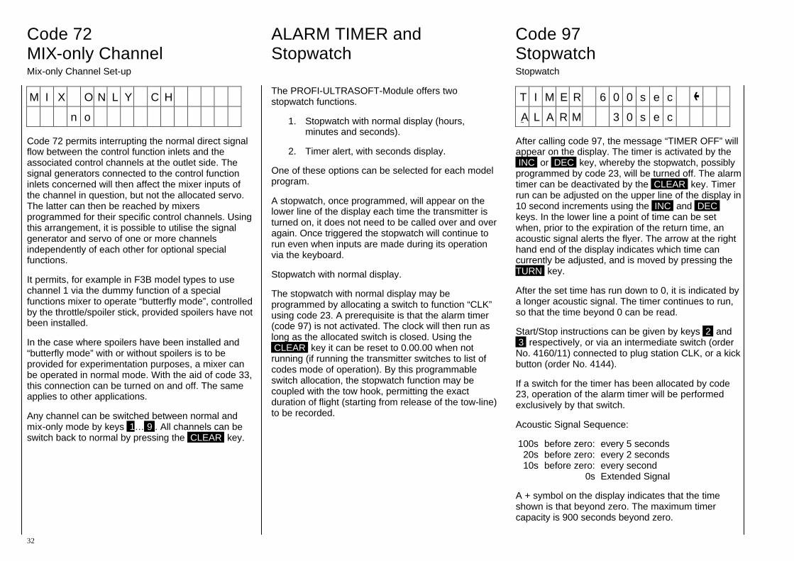
M I X O N L Y C H
n o
Code 72 permits interrupting the normal direct signal flow between the control function inlets and the associated control channels at the outlet side. The signal generators connected to the control function inlets concerned will then affect the mixer inputs of the channel in question, but not the allocated servo. The latter can then be reached by mixers programmed for their specific control channels. Using this arrangement, it is possible to utilise the signal generator and servo of one or more channels independently of each other for optional special functions.
It permits, for example in F3B model types to use channel 1 via the dummy function of a special functions mixer to operate “butterfly mode”, controlled by the throttle/spoiler stick, provided spoilers have not been installed.
In the case where spoilers have been installed and “butterfly mode” with or without spoilers is to be provided for experimentation purposes, a mixer can be operated in normal mode. With the aid of code 33, this connection can be turned on and off. The same applies to other applications.
Any channel can be switched between normal and mix-only mode by keys 1… 9 . All channels can be switch back to normal by pressing the CLEAR key.
The PROFI-ULTRASOFT-Module offers two stopwatch functions.
1. Stopwatch with normal display (hours, minutes and seconds).
2. Timer alert, with seconds display.
One of these options can be selected for each model program.
A stopwatch, once programmed, will appear on the lower line of the display each time the transmitter is turned on, it does not need to be called over and over again. Once triggered the stopwatch will continue to run even when inputs are made during its operation via the keyboard.
Stopwatch with normal display.
The stopwatch with normal display may be programmed by allocating a switch to function “CLK” using code 23. A prerequisite is that the alarm timer (code 97) is not activated. The clock will then run as long as the allocated switch is closed. Using the CLEAR key it can be reset to 0.00.00 when not running (if running the transmitter switches to list of codes mode of operation). By this programmable switch allocation, the stopwatch function may be coupled with the tow hook, permitting the exact duration of flight (starting from release of the tow-line) to be recorded.
T I M E R 6 0 0 s e c
A L A R M 3 0 s e c
After calling code 97, the message “TIMER OFF” will appear on the display. The timer is activated by the INC or DEC key, whereby the stopwatch, possibly programmed by code 23, will be turned off. The alarm timer can be deactivated by the CLEAR key. Timer run can be adjusted on the upper line of the display in 10 second increments using the INC and DEC keys. In the lower line a point of time can be set when, prior to the expiration of the return time, an acoustic signal alerts the flyer. The arrow at the right hand end of the display indicates which time can currently be adjusted, and is moved by pressing the TURN key.
After the set time has run down to 0, it is indicated by a longer acoustic signal. The timer continues to run, so that the time beyond 0 can be read.
Start/Stop instructions can be given by keys 2 and 3 respectively, or via an intermediate switch (order No. 4160/11) connected to plug station CLK, or a kick button (order No. 4144).
If a switch for the timer has been allocated by code 23, operation of the alarm timer will be performed exclusively by that switch.
Acoustic Signal Sequence:
100s before zero: every 5 seconds 20s before zero: every 2 seconds 10s before zero: every second 0s Extended Signal
A + symbol on the display indicates that the time shown is that beyond zero. The maximum timer capacity is 900 seconds beyond zero.
Code 98 Code 77 Operating Timer FAIL SAFE Transmitter Operating Timer Programming the Fail Safe
33
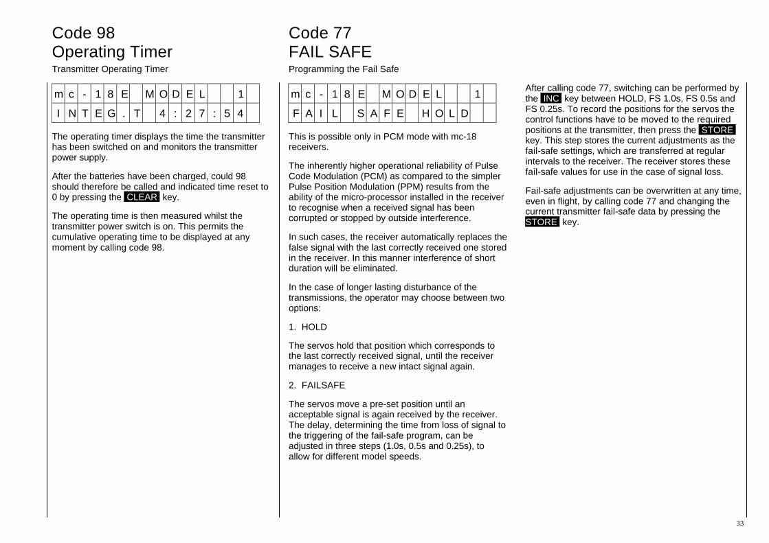
m c - 1 8 E M O D E L 1
I N T E G . T 4 : 2 7 : 5 4
The operating timer displays the time the transmitter has been switched on and monitors the transmitter power supply.
After the batteries have been charged, could 98 should therefore be called and indicated time reset to 0 by pressing the CLEAR key.
The operating time is then measured whilst the transmitter power switch is on. This permits the cumulative operating time to be displayed at any moment by calling code 98.
m c - 1 8 E M O D E L 1
F A I L S A F E H O L D
This is possible only in PCM mode with mc-18 receivers.
The inherently higher operational reliability of Pulse Code Modulation (PCM) as compared to the simpler Pulse Position Modulation (PPM) results from the ability of the micro-processor installed in the receiver to recognise when a received signal has been corrupted or stopped by outside interference.
In such cases, the receiver automatically replaces the false signal with the last correctly received one stored in the receiver. In this manner interference of short duration will be eliminated.
In the case of longer lasting disturbance of the transmissions, the operator may choose between two options:
1. HOLD
The servos hold that position which corresponds to the last correctly received signal, until the receiver manages to receive a new intact signal again.
2. FAILSAFE
The servos move a pre-set position until an acceptable signal is again received by the receiver. The delay, determining the time from loss of signal to the triggering of the fail-safe program, can be adjusted in three steps (1.0s, 0.5s and 0.25s), to allow for different model speeds.
After calling code 77, switching can be performed by the INC key between HOLD, FS 1.0s, FS 0.5s and FS 0.25s. To record the positions for the servos the control functions have to be moved to the required positions at the transmitter, then press the STORE key. This step stores the current adjustments as the fail-safe settings, which are transferred at regular intervals to the receiver. The receiver stores these fail-safe values for use in the case of signal loss.
Fail-safe adjustments can be overwritten at any time, even in flight, by calling code 77 and changing the current transmitter fail-safe data by pressing the STORE key.
Code 78 Code 88 Code 99 FAIL SAFE BAT Input Lock Transmitter Lock Activating Battery Fail-Safe Code Lock for Keyboard Input Numerical Transmitter Lock
34
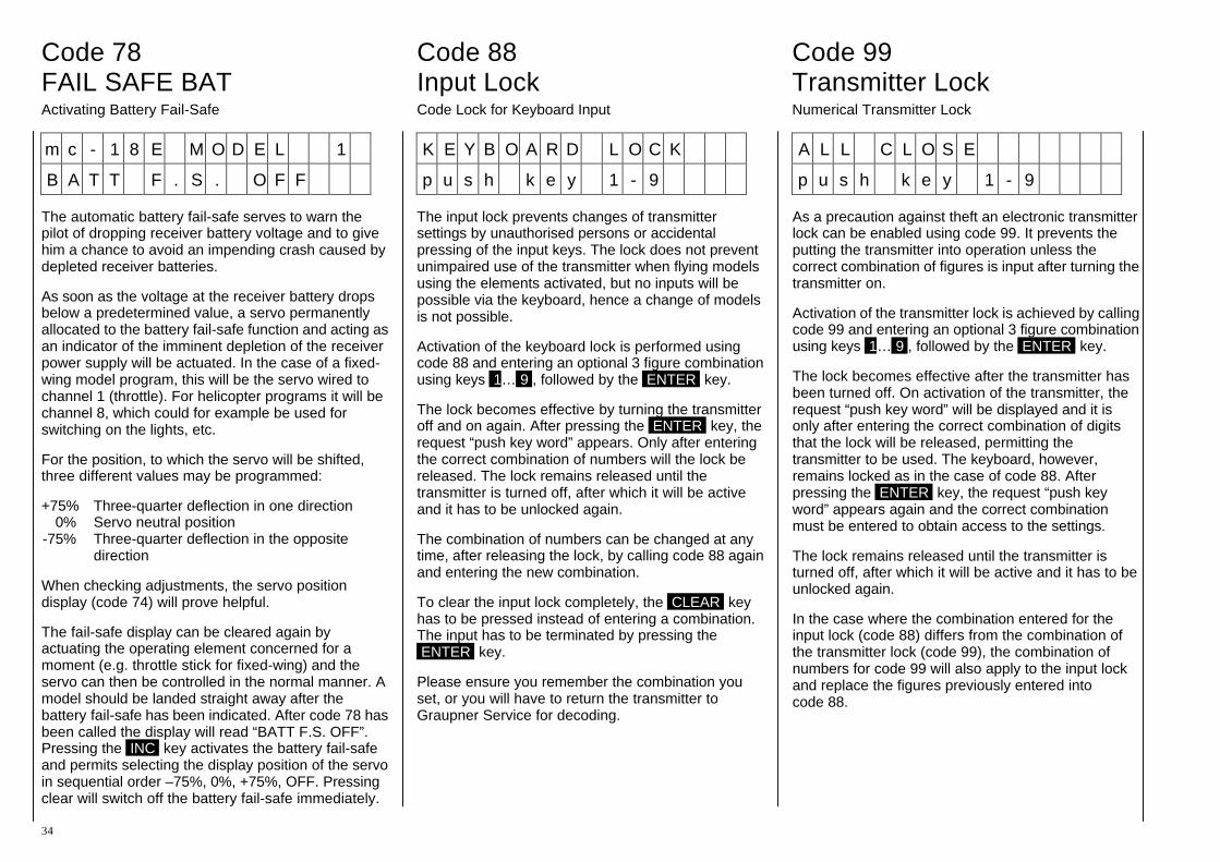
m c - 1 8 E M O D E L 1
B A T T F . S . O F F
The automatic battery fail-safe serves to warn the pilot of dropping receiver battery voltage and to give him a chance to avoid an impending crash caused by depleted receiver batteries.
As soon as the voltage at the receiver battery drops below a predetermined value, a servo permanently allocated to the battery fail-safe function and acting as an indicator of the imminent depletion of the receiver power supply will be actuated. In the case of a fixed-wing model program, this will be the servo wired to channel 1 (throttle). For helicopter programs it will be channel 8, which could for example be used for switching on the lights, etc.
For the position, to which the servo will be shifted, three different values may be programmed:
+75% Three-quarter deflection in one direction 0% Servo neutral position -75% Three-quarter deflection in the opposite
direction
When checking adjustments, the servo position display (code 74) will prove helpful.
The fail-safe display can be cleared again by actuating the operating element concerned for a moment (e.g. throttle stick for fixed-wing) and the servo can then be controlled in the normal manner. A model should be landed straight away after the battery fail-safe has been indicated. After code 78 has been called the display will read “BATT F.S. OFF”. Pressing the INC key activates the battery fail-safe and permits selecting the display position of the servo in sequential order –75%, 0%, +75%, OFF. Pressing clear will switch off the battery fail-safe immediately.
K E Y B O A R D L O C K
p u s h k e y 1 - 9
The input lock prevents changes of transmitter settings by unauthorised persons or accidental pressing of the input keys. The lock does not prevent unimpaired use of the transmitter when flying models using the elements activated, but no inputs will be possible via the keyboard, hence a change of models is not possible.
Activation of the keyboard lock is performed using code 88 and entering an optional 3 figure combination using keys 1… 9 , followed by the ENTER key.
The lock becomes effective by turning the transmitter off and on again. After pressing the ENTER key, the request “push key word” appears. Only after entering the correct combination of numbers will the lock be released. The lock remains released until the transmitter is turned off, after which it will be active and it has to be unlocked again.
The combination of numbers can be changed at any time, after releasing the lock, by calling code 88 again and entering the new combination.
To clear the input lock completely, the CLEAR key has to be pressed instead of entering a combination. The input has to be terminated by pressing the ENTER key.
Please ensure you remember the combination you set, or you will have to return the transmitter to Graupner Service for decoding.
A L L C L O S E
p u s h k e y 1 - 9
As a precaution against theft an electronic transmitter lock can be enabled using code 99. It prevents the putting the transmitter into operation unless the correct combination of figures is input after turning the transmitter on.
Activation of the transmitter lock is achieved by calling code 99 and entering an optional 3 figure combination using keys 1… 9 , followed by the ENTER key.
The lock becomes effective after the transmitter has been turned off. On activation of the transmitter, the request “push key word” will be displayed and it is only after entering the correct combination of digits that the lock will be released, permitting the transmitter to be used. The keyboard, however, remains locked as in the case of code 88. After pressing the ENTER key, the request “push key word” appears again and the correct combination must be entered to obtain access to the settings.
The lock remains released until the transmitter is turned off, after which it will be active and it has to be unlocked again.
In the case where the combination entered for the input lock (code 88) differs from the combination of the transmitter lock (code 99), the combination of numbers for code 99 will also apply to the input lock and replace the figures previously entered into code 88.
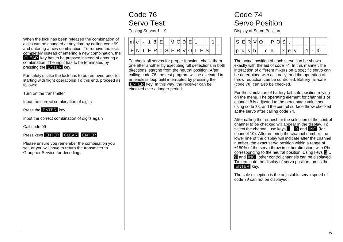
Code 76 Code 74 Servo Test Servo Position Testing Servos 1 – 9 Display of Servo Position
35
When the lock has been released the combination of digits can be changed at any time by calling code 99 and entering a new combination. To remove the lock completely instead of entering a new combination, the CLEAR key has to be pressed instead of entering a combination. The input has to be terminated by pressing the ENTER key.
For safety’s sake the lock has to be removed prior to starting with flight operations! To this end, proceed as follows:
Turn on the transmitter
Input the correct combination of digits
Press the ENTER key
Input the correct combination of digits again
Call code 99
Press keys ENTER CLEAR ENTER
Please ensure you remember the combination you set, or you will have to return the transmitter to Graupner Service for decoding.
m c - 1 8 E M O D E L 1
E N T E R = S E R V O T E S T
To check all servos for proper function, check them one after another by executing full deflections in both directions, starting from the neutral position. After calling code 76, the test program will be executed in an endless loop until interrupted by pressing the ENTER key. In this way, the receiver can be checked over a longer period.
S E R V O P O S .
p u s h c h k e y 1 - 10
The actual position of each servo can be shown exactly with the aid of code 74. In this manner, the interaction of different mixers on a specific servo can be determined with accuracy, and the operation of throw reduction can be controlled. Battery fail-safe (code 78) can also be checked.
For the simulation of battery fail-safe position relying on the menu. The operating element for channel 1 or channel 8 is adjusted to the percentage value set using code 78, and the control surface throw checked at the servo after calling code 74.
After calling the request for the selection of the control channel to be checked will appear in the display. To select the channel, use keys 1… 9 and INC (for channel 10). After entering the channel number, the lower line of the display will indicate after the channel number, the exact servo position within a range of ±150% of the servo throw in either direction, with 0% corresponding to the neutral position. Using keys 1… 9 and INC , other control channels can be displayed. To terminate the display of servo position, press the ENTER key.
The sole exception is the adjustable servo speed of code 79 can not be displayed.
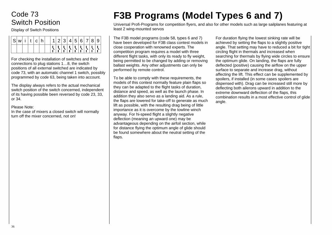
Code 73 Switch Position Display of Switch Positions
36
F3B Programs (Model Types 6 and 7) Universal Profi-Programs for competition flyers, and also for other models such as large sailplanes featuring at least 2 wing-mounted servos
S w i t c h 1 2 3 4 5 6 7 8 9
For checking the installation of switches and their connections to plug stations 1…8, the switch positions of all external switched are indicated by code 73, with an automatic channel 1 switch, possibly programmed by code 63, being taken into account.
The display always refers to the actual mechanical switch position of the switch concerned, independent of its having possible been reversed by code 23, 33, or 34.
Please Note: In the case of mixers a closed switch will normally turn off the mixer concerned, not on!
The F3B model programs (code 58, types 6 and 7) have been developed for F3B class contest models in close cooperation with renowned experts. The competition program requires a model with three different flight tasks, with only its ready to fly weight, being permitted to be changed by adding or removing ballast weights. Any other adjustments can only be performed by remote control.
To be able to comply with these requirements, the models of this contest normally feature plain flaps so they can be adapted to the flight tasks of duration, distance and speed, as well as the launch phase. In addition they also servo as a landing aid. As a rule, the flaps are lowered for take-off to generate as much lift as possible, with the resulting drag being of little importance as it is overcome by the towline winch anyway. For hi-speed flight a slightly negative deflection (meaning an upward one) may be advantageous depending on the airfoil section, while for distance flying the optimum angle of glide should be found somewhere about the neutral setting of the flaps.
For duration flying the lowest sinking rate will be achieved by setting the flaps to a slightly positive angle. That setting may have to reduced a bit for tight circling flight in thermals and increased when searching for thermals by flying wide circles to ensure the optimum glide. On landing, the flaps are fully deflected (positive) causing the airflow on the upper surface to separate and increase drag, without affecting the lift. This effect can be supplemented by spoilers, if installed (in some cases spoilers are dispensed with). Drag can be increased still more by deflecting both ailerons upward in addition to the extreme downward deflection of the flaps, this combination results in a most effective control of glide angle.

37
The latter set-up is also called “butterfly” or “crow” function. In some cases separate ailerons and plain flaps are replaced by one-piece full-span flaps, which are simultaneously operated as ailerons and plain flaps (called flaperons). Performance flying means flying at very low drag, in any flight situation and attitude, including turns and circling flight.
Lowest drag is achieved only when the airflow hits the model head-on, that is when side-slipping (with the flow having a component along the lateral axis) is avoided. This condition is simplified by differential ailerons used in conjunction with the aileron – rudder mix, whereby the negative yawing moment is compensated for. Additional mixers increase the effect of the control surfaces (plain flaps – ailerons), ensure uniform lift distribution (ailerons – plain flaps), increase manoeuvrability (plain flaps – elevator) and adjust elevator trim for deflection of the flaps.
In addition to the normal actuation of the plain flaps, via slider-type potentiometer or a step switch, the F3B programs offer storable pre-sets for plain flaps and elevator adjustments for any flight task and for take-off, all of which can be called via a switch. Which of the operating elements is to be used for in-flight fine tuning of the flaps settings can be determined separately for any of the presets.
The change of the flap and elevator settings when switching from one preset to another one is not made abruptly, but achieved using separately adjustable time constants. Other sensible options, such as reduction of aileron differential (for butterfly function), co-switchable PROFITRIM-module with optional storing of adjustment data, etc., simplify handling of a model for the demanding contest flyer and assist him in his endeavour to achieve optimum performance.
The two F3B programs differ only in that model type 6 is meant for flaps which are operated by a common servo, while each aileron is operated by a separate servo (in all 3 wing-mounted servos), while type 7 refers to a set-up where each flap and aileron is operated by its own servo (4 wing-mounted servos).
In the case of type 6, the flaps can be moved only in unison, so the aileron flap mixer is omitted. All other options are alike for type 6 and type 7, so the two programs may be described together.
Model types 6 and 7 provide nearly all of the options of types 1…5, with the sole difference that those functions which are needed for power models only are omitted, such as throttle reduction (code 17) and automatic manoeuvre (code 66). As opposed to types 1…5, seven freely programmable mixers are available for type 6 and 7. Code 23 (switch allocation) takes the expansion of the F3B program into account when compared to normal types.
In addition types 6 and 7 provide the following functions (listed in sequential order of their descriptions:
Code Display Meaning Page
23 SWITCH FUNCT. External Switch Allocation 38 52 STRT-SPD-DIST Flight Trim: Start, Speed, Distance 39 53 FLAP TRIM ASS Flap Trim Assignment 39 92 SMOOTH SWITCH Servo Transit Time Set -up 39 41 AILE RUDD Aileron to Rudder Mix 40 42 AILE FLAP Aileron to Flap Mix 40 49 FLAP AILERON Flap to Aileron Mix 40 91 AN. TRIM SW Set-up for PROFITRIM 42 48 FLAP ELEV Flap to Elevator Mix 42 47 ELEV FLAP Elevator to Flap Mix 42 44 BRK ELEV Spoiler to Elevator Mix 43 45 BRK FLAP Spoiler to Flap Mix 43 46 BRK AILERON Spoiler to Aileron Mix 43 54 DIFF REDUCT Reduction of Aileron Differential 43
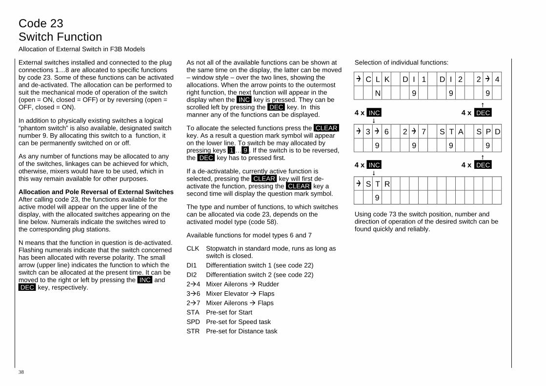
Code 23 Switch Function Allocation of External Switch in F3B Models
38
External switches installed and connected to the plug connections 1…8 are allocated to specific functions by code 23. Some of these functions can be activated and de-activated. The allocation can be performed to suit the mechanical mode of operation of the switch (open = ON, closed = OFF) or by reversing (open = OFF, closed = ON).
In addition to physically existing switches a logical “phantom switch” is also available, designated switch number 9. By allocating this switch to a function, it can be permanently switched on or off.
As any number of functions may be allocated to any of the switches, linkages can be achieved for which, otherwise, mixers would have to be used, which in this way remain available for other purposes.
Allocation and Pole Reversal of External Switches After calling code 23, the functions available for the active model will appear on the upper line of the display, with the allocated switches appearing on the line below. Numerals indicate the switches wired to the corresponding plug stations.
N means that the function in question is de-activated. Flashing numerals indicate that the switch concerned has been allocated with reverse polarity. The small arrow (upper line) indicates the function to which the switch can be allocated at the present time. It can be moved to the right or left by pressing the INC and DEC key, respectively.
As not all of the available functions can be shown at the same time on the display, the latter can be moved – window style – over the two lines, showing the allocations. When the arrow points to the outermost right function, the next function will appear in the display when the INC key is pressed. They can be scrolled left by pressing the DEC key. In this manner any of the functions can be displayed.
To allocate the selected functions press the CLEAR key. As a result a question mark symbol will appear on the lower line. To switch be may allocated by pressing keys 1 … 9 . If the switch is to be reversed, the DEC key has to pressed first.
If a de-activatable, currently active function is selected, pressing the CLEAR key will first de-activate the function, pressing the CLEAR key a second time will display the question mark symbol.
The type and number of functions, to which switches can be allocated via code 23, depends on the activated model type (code 58).
Available functions for model types 6 and 7
CLK Stopwatch in standard mode, runs as long as switch is closed.
DI1 Differentiation switch 1 (see code 22) DI2 Differentiation switch 2 (see code 22) 2 4 Mixer Ailerons Rudder 3 6 Mixer Elevator Flaps 2 7 Mixer Ailerons Flaps STA Pre-set for Start SPD Pre-set for Speed task STR Pre-set for Distance task
Selection of individual functions:
C L K D I 1 D I 2 2 4
N 9 9 9 ↑↑ 4 x INC 4 x DEC ↓↓
3 6 2 7 S T A S P D
9 9 9 9 ↑↑ 4 x INC 4 x DEC ↓↓
S T R
9
Using code 73 the switch position, number and direction of operation of the desired switch can be found quickly and reliably.

Code 52 Code 53 Code 92 TAKE-OFF, SPD, DIST Flap Trim Arrangement Switch Slow-Down Pre-sets for the Flight Tasks Signal Generator Selection for the Flap Function Elevator / Flap Transit Time Slow-Down
39
S T A R T F L A P + 5 8
E L E V + 7
Code 52 permits storing the flap and elevator settings for Speed, Distance and for the Take-Off phases. However, the allocation of the corresponding external switches has to be performed first using code 23.
A possibly active aileron rudder mixer (code 41) will automatically be switched off when the Speed flight task is selected on.
For these adjustments the corresponding external switch has to be actuated after calling code 52, whereupon the values for elevator and flaps will be displayed. Adjustments are made using the INC and DEC keys, by pressing the TURN key the elevator and flap adjustments can be changed and the value set directly to 0 by the CLEAR key.
N O R M A L I N P 6 = O N
I N P 7 = O F F
The operating elements for actuating the flaps can be selected separately from the pre-set flight tasks duration (normal), distance, speed and the start phase. Operating elements can be slider-type, rotary potentiometers or step switches, which are wired to the plug stations for channel 6 and 7. Between the two inlets a fundamental difference exists.
While the signal generator wired to channel input 6 also affects mixer code 48 (flap elevator), inlet 7 may be used for elevator independent flap trim. For any of these four phases of flight you can select whether the flaps function is to be performed by the signal generator of channel 6 or 7, or by neither of these. For example, you may actuate the flaps for the duration phase by slider-type control 6, for distance flight by a switch module providing three switch positions, and for the start and speed phases exclusively by the pre-set values without any further adjustment being possible.
Adjustment After calling code 53, a selection menu appears on the display for the active flight phase concerned, selected by actuating the external switch in question. Using the INC and DEC keys you can switch the values between ON and OFF, or the CLEAR key for OFF. Using the TURN key permits swapping between adjustment of channel 6 or 7. For selection of another flight phase the corresponding switch has to be actuated, whereupon the display will change accordingly.
S m o o t h E L E = O F F
F L A = 3 . 3 s
In order to avoid abrupt elevator and flap deflection when switching between the pre-sets for the various flight phases, the transit time of the servos for elevator and flap can be adjusted separately, by code 92, within the range 0.5s to 30s for full servo throw. In the case of the elevator this slowing down is effective only when switching from one flight phase to another one, not in the course of normal control. In the case of flaps it is permanently effective, so the flaps can be operated smoothly with a 3 position switch without jerking.
After calling code 92, the transit time can be adjusted by the INC and DEC keys. For smaller delay values the steps are very small and not every change will show on the display. Steps increase in size as the delay value increases. By pressing the CLEAR key the slow-down is cancelled, while pressing the TURN key swaps between adjusting the elevator and flaps setting.
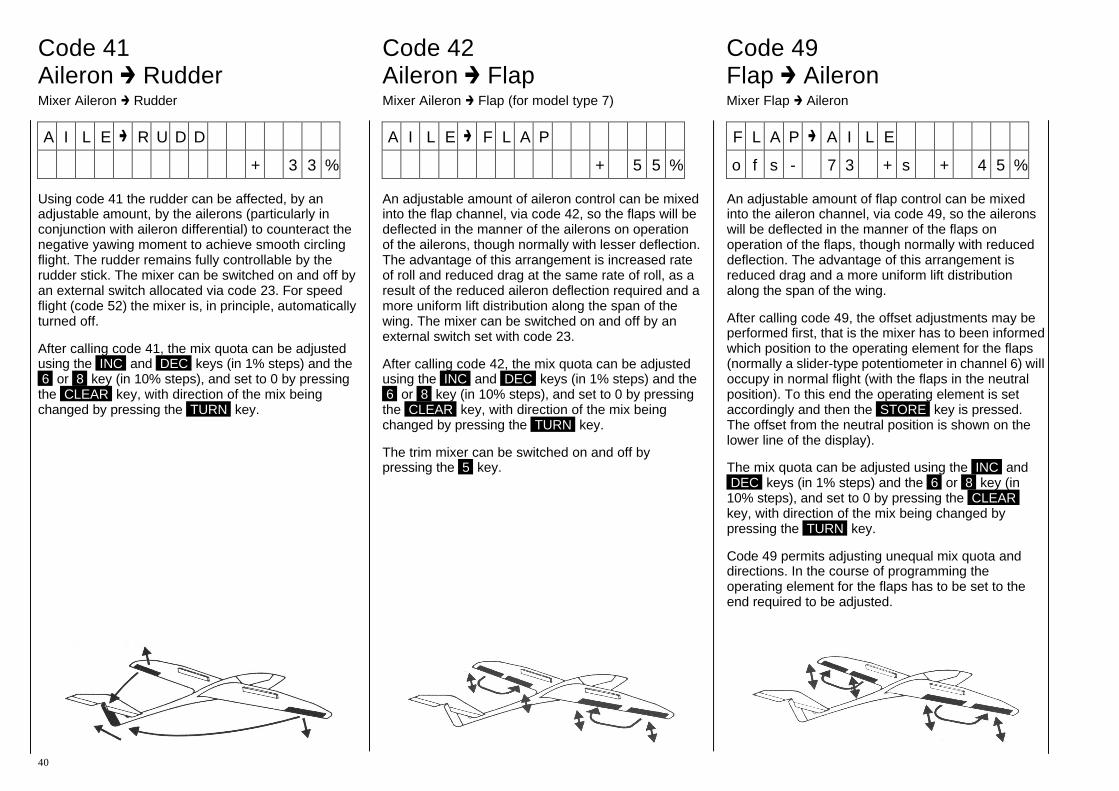
Code 41 Code 42 Code 49 Aileron Rudder Aileron Flap Flap Aileron Mixer Aileron Rudder Mixer Aileron Flap (for model type 7) Mixer Flap Aileron
40
A I L E R U D D
+ 3 3 %
Using code 41 the rudder can be affected, by an adjustable amount, by the ailerons (particularly in conjunction with aileron differential) to counteract the negative yawing moment to achieve smooth circling flight. The rudder remains fully controllable by the rudder stick. The mixer can be switched on and off by an external switch allocated via code 23. For speed flight (code 52) the mixer is, in principle, automatically turned off.
After calling code 41, the mix quota can be adjusted using the INC and DEC keys (in 1% steps) and the 6 or 8 key (in 10% steps), and set to 0 by pressing the CLEAR key, with direction of the mix being changed by pressing the TURN key.
A I L E F L A P
+ 5 5 %
An adjustable amount of aileron control can be mixed into the flap channel, via code 42, so the flaps will be deflected in the manner of the ailerons on operation of the ailerons, though normally with lesser deflection. The advantage of this arrangement is increased rate of roll and reduced drag at the same rate of roll, as a result of the reduced aileron deflection required and a more uniform lift distribution along the span of the wing. The mixer can be switched on and off by an external switch set with code 23.
After calling code 42, the mix quota can be adjusted using the INC and DEC keys (in 1% steps) and the 6 or 8 key (in 10% steps), and set to 0 by pressing the CLEAR key, with direction of the mix being changed by pressing the TURN key.
The trim mixer can be switched on and off by pressing the 5 key.
F L A P A I L E
o f s - 7 3 + s + 4 5 %
An adjustable amount of flap control can be mixed into the aileron channel, via code 49, so the ailerons will be deflected in the manner of the flaps on operation of the flaps, though normally with reduced deflection. The advantage of this arrangement is reduced drag and a more uniform lift distribution along the span of the wing.
After calling code 49, the offset adjustments may be performed first, that is the mixer has to been informed which position to the operating element for the flaps (normally a slider-type potentiometer in channel 6) will occupy in normal flight (with the flaps in the neutral position). To this end the operating element is set accordingly and then the STORE key is pressed. The offset from the neutral position is shown on the lower line of the display).
The mix quota can be adjusted using the INC and DEC keys (in 1% steps) and the 6 or 8 key (in 10% steps), and set to 0 by pressing the CLEAR key, with direction of the mix being changed by pressing the TURN key.
Code 49 permits adjusting unequal mix quota and directions. In the course of programming the operating element for the flaps has to be set to the end required to be adjusted.

PROFITRIM-Module
41
The PROFITRIM external module (order No. 4109) permits additional trimming of all flap and aileron functions by four rotary trimmers. The latter are allocated to the following functions:
1 = Aileron Trim (aileron function) 2 = Aileron Trim (flap function) 3 = Flap Trim (aileron function) 4 = Flap Trim (flap function)
The trimmers can be turned on and off singly or in any desired combination, with their neutral positions corresponding to the programmed settings.
On deactivation of the trimmers, the adjusted value will be stored. It if thus possible to establish optimum settings in flight with the trimmers turned on, and to protect them against being accidentally changed when turned off. These data values will only be stored up to the next time the trimmer is turned on, whereupon the initial reference point, set in the course of programming will be re-established.
Trimmer 3 cannot be used in the case of type 6 models, since the flaps can only be driven in the same direction.
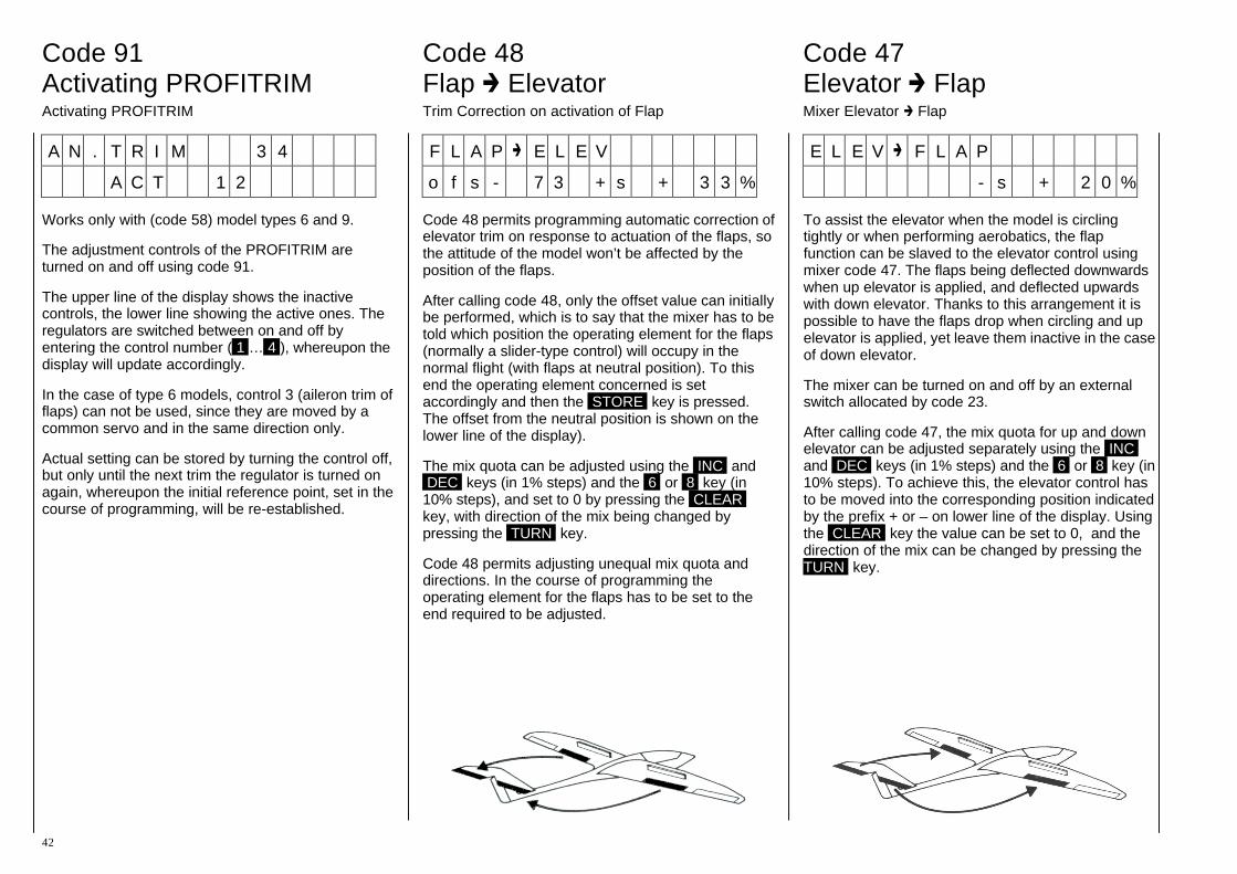
Code 91 Code 48 Code 47 Activating PROFITRIM Flap Elevator Elevator Flap Activating PROFITRIM Trim Correction on activation of Flap Mixer Elevator Flap
42
A N . T R I M 3 4
A C T 1 2
Works only with (code 58) model types 6 and 9.
The adjustment controls of the PROFITRIM are turned on and off using code 91.
The upper line of the display shows the inactive controls, the lower line showing the active ones. The regulators are switched between on and off by entering the control number ( 1 … 4 ), whereupon the display will update accordingly.
In the case of type 6 models, control 3 (aileron trim of flaps) can not be used, since they are moved by a common servo and in the same direction only.
Actual setting can be stored by turning the control off, but only until the next trim the regulator is turned on again, whereupon the initial reference point, set in the course of programming, will be re-established.
F L A P E L E V
o f s - 7 3 + s + 3 3 %
Code 48 permits programming automatic correction of elevator trim on response to actuation of the flaps, so the attitude of the model won’t be affected by the position of the flaps.
After calling code 48, only the offset value can initially be performed, which is to say that the mixer has to be told which position the operating element for the flaps (normally a slider-type control) will occupy in the normal flight (with flaps at neutral position). To this end the operating element concerned is set accordingly and then the STORE key is pressed. The offset from the neutral position is shown on the lower line of the display).
The mix quota can be adjusted using the INC and DEC keys (in 1% steps) and the 6 or 8 key (in 10% steps), and set to 0 by pressing the CLEAR key, with direction of the mix being changed by pressing the TURN key.
Code 48 permits adjusting unequal mix quota and directions. In the course of programming the operating element for the flaps has to be set to the end required to be adjusted.
E L E V F L A P
- s + 2 0 %
To assist the elevator when the model is circling tightly or when performing aerobatics, the flap function can be slaved to the elevator control using mixer code 47. The flaps being deflected downwards when up elevator is applied, and deflected upwards with down elevator. Thanks to this arrangement it is possible to have the flaps drop when circling and up elevator is applied, yet leave them inactive in the case of down elevator.
The mixer can be turned on and off by an external switch allocated by code 23.
After calling code 47, the mix quota for up and down elevator can be adjusted separately using the INC and DEC keys (in 1% steps) and the 6 or 8 key (in 10% steps). To achieve this, the elevator control has to be moved into the corresponding position indicated by the prefix + or – on lower line of the display. Using the CLEAR key the value can be set to 0, and the direction of the mix can be changed by pressing the TURN key.

Codes 44, 45, 46 and 54 Butterfly Function as Landing Aid
43
The “butterfly” function serves as a landing aid by controlling the glide slope. It may be used alone or in conjunction with spoilers which are possibly in use already.
On operation of the spoiler channel control, the flaps will be deflected downward, while the ailerons are moved upwards. The elevator is also re-trimmed by the mixers so as to maintain the longitudinal attitude of the model in normal flight. All of the three mixers can be adjusted individually and, of course, they can be used alone. For example, code 44 (spoiler elevator) can be used in conjunction with normal spoilers to retain the glide path angle on extension of the spoilers, while the two other mixers have been set inoperative. In the case of full span ailerons, which are also used as flaps (flaperons), mixers 45 (spoiler
ailerons) and 44 (spoilers elevator) may be used in unison to deflect the flaperons to the upper limit and to re-trim the elevator to suit.
When using aileron differential (code 22), aileron effectiveness will be considerably impaired by the extreme deflection of the ailerons via the butterfly function, aileron downward deflection being reduced or even suppressed entirely as a result of the differential. Deflections in the upward direction cannot be increased any more as the ailerons are already at their limits.
A remedy is provided by code 54 (reduction of differential), whereby the degree of differential is continuously, and adjustably, reduced or entirely cancelled on actuation of the butterfly function.
Adjustments: Mixers 44, 45 and 46 are already allocated as per their functions, with mix quota having been set to 0, they are effectively inactive.
Code 44 Spoilers Elevator Code 45 Spoilers Flaps Code 46 Spoilers Ailerons
To activate them, input the corresponding code number, whereupon the associated adjustment menu will be shown on the display. The first adjustment to be made is the offset, which is to say the mixer has to be told which position the operating element for the spoilers (throttle/spoiler control stick) normally occupies (spoilers retracted, and the no butterfly position of ailerons and flaps). To this end the operating element concerned is set accordingly and then the STORE key is pressed. The offset from the neutral position is shown on the lower line of the display). The mix quota can be adjusted using the INC and DEC keys (in 1% steps) and the 6 or 8 key (in 10% steps), and set to 0 by pressing the CLEAR key, with direction of the mix being changed by pressing the TURN key.
To deactivate the butterfly function, the mix quota of mixers 44, 45 and 46 have to be set to 0.
If spoilers are not provided, control channel 1 in code 72 (mix-only channel) can be de-coupled from the stick and, with the aid of a mixer, used for other purposes.
B R K E L E V
o f s - 7 3 - 2 5 %
B R K F L A P
o f s - 7 3 + 1 0 0 %
B R K A I L E R O N
o f s - 7 3 - 9 0 %
Code 54 Adjusting the Reduction of Differential
After calling code 54, the magnitude of the reduction of differential can be adjusted using the INC and DEC keys, with 0% meaning that the differential remains unchanged on activation of the spoiler/ butterfly control, while a value of 100% indicates that differential is completely removed in the case of maximum butterfly function. The transition from normal to reduced differential is linear to spoiler actuation. The CLEAR key permits resetting the reduction to 0% and completely cancelling differential reduction.
D I F F R E D U C T I O N
8 5 %

Programming Examples for Fixed-Wing Models
44
In case you have become slightly confused by the unusually large number of functions offered in the preceding chapters of these instructions, the following pages show you by way of example, how a practical adjustment of a model can be programmed in a minimum of time. In doing so, the essential functions will be activated, while the “deluxe” options meant for the competition pilot will not, initially, be taken into consideration. In the following chapters this basic program will the be expanded by additional options, followed by a few examples for the Profi’s bag of tricks. Here the basic principles of computer R/C will become clear.
From the extensive range of functions you select only those which are actually required and forget the rest of them. If, in the course of time, you need more all you have to do is activate additional functions.
Be sure to duplicate the following examples step by step, so you won’t forget or overlook anything. In this manner you’ll actually get automatically familiar with your R/C equipment and won’t consider it nearly as complicated as it may have appeared at first glance.
1.) Preparations
You have installed the module into the transmitter as per the instructions. Close the case of the transmitter again and turned the transmitter on. The display will read:
m c - 1 8 E M O D E L 1
9 . 6 V P C M
Depending on what kind of module had been installed previously in your transmitter the display may show another model number or another modulation mode.
2.) Executing RESET (Important)
Call model memory 1 and clear it completely. To do this input:
ENTER 5 6 ENTER 1 CLEAR ENTER
If the transmitter had previously been switched to PCM you now have the basic position of the display again. If not, the request will appear to turn the transmitter off. This is because it has been switched to the default position of PCM modulation. Comply with the request and then turn it on again a moment later, thereafter you will be in the basic position.
For safety’s sake, so you won’t forget it later, execute a reset (right now) on all the remainder of the model memories. To do this, input:
ENTER 5 6 ENTER 2 CLEAR ENTER
ENTER 5 6 ENTER 3 CLEAR ENTER … ENTER 5 6 ENTER 7 CLEAR ENTER … ( ENTER 5 6 ENTER 3 0 CLEAR ENTER )
This procedure needs only to be performed once in order to positively delete any programming parts and data which may have been stored in the transmitter memory by an earlier used module, and could still be stored. These program fragments may cause a malfunction if not deleted.
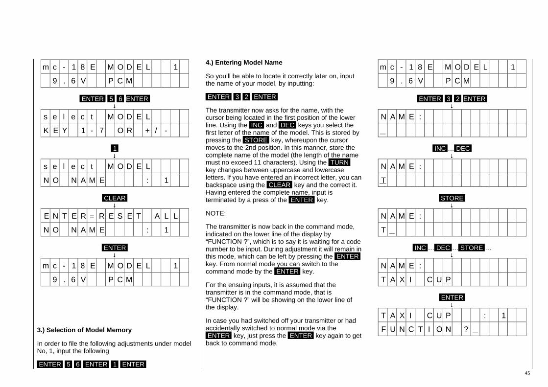
45
m c - 1 8 E M O D E L 1
9 . 6 V P C M
ENTER 5 6 ENTER ↓↓
s e l e c t M O D E L
K E Y 1 - 7 O R + / - 1 ↓↓
s e l e c t M O D E L
N O N A M E : 1
CLEAR ↓↓
E N T E R = R E S E T A L L
N O N A M E : 1
ENTER ↓↓
m c - 1 8 E M O D E L 1
9 . 6 V P C M
3.) Selection of Model Memory
In order to file the following adjustments under model No, 1, input the following
ENTER 5 6 ENTER 1 ENTER
4.) Entering Model Name
So you’ll be able to locate it correctly later on, input the name of your model, by inputting:
ENTER 3 2 ENTER
The transmitter now asks for the name, with the cursor being located in the first position of the lower line. Using the INC and DEC keys you select the first letter of the name of the model. This is stored by pressing the STORE key, whereupon the cursor moves to the 2nd position. In this manner, store the complete name of the model (the length of the name must no exceed 11 characters). Using the TURN key changes between uppercase and lowercase letters. If you have entered an incorrect letter, you can backspace using the CLEAR key and the correct it. Having entered the complete name, input is terminated by a press of the ENTER key.
NOTE:
The transmitter is now back in the command mode, indicated on the lower line of the display by “FUNCTION ?”, which is to say it is waiting for a code number to be input. During adjustment it will remain in this mode, which can be left by pressing the ENTER key. From normal mode you can switch to the command mode by the ENTER key.
For the ensuing inputs, it is assumed that the transmitter is in the command mode, that is “FUNCTION ?” will be showing on the lower line of the display.
In case you had switched off your transmitter or had accidentally switched to normal mode via the ENTER key, just press the ENTER key again to get back to command mode.
m c - 1 8 E M O D E L 1
9 . 6 V P C M
ENTER 3 2 ENTER ↓↓
N A M E :
INC … DEC ↓↓
N A M E :
T
STORE ↓↓
N A M E :
T
INC … DEC … STORE … ↓↓
N A M E :
T A X I C U P
ENTER ↓↓
T A X I C U P : 1
F U N C T I O N ?

Programming Examples for Fixed-Wing Models
46
5.) Defining Stick Allocation
Set the control stick allocation you are accustomed to by entering:
5 7 ENTER
Thereupon the lower line of the display will read:
MODE 1
Now press one of the keys 1 … 4 , to suit your normal control mode:
1 = Throttle and Ailerons on the right Elevator and Rudder on the left
2 = Throttle and Rudder on the left Ailerons and Elevator on the right
3 = Throttle and Rudder on the right Ailerons and Elevator on the left
4 = Throttle and Ailerons on the left Elevator and Rudder on the right
The figure on the display will change accordingly. Terminate the input by pressing the ENTER key and you are once again back in command mode.
T A X I C U P : 1
F U N C T I O N ?
5 7 ENTER ↓↓
T A X I C U P : 1
M O D E 1 2 ↓↓
T A X I C U P : 1
M O D E 2
ENTER ↓↓
T A X I C U P : 1
F U N C T I O N ?
6.) Defining the Model Type
The previous inputs were universally applicable to all types of
model. Now you select the type of model to which your actual model corresponds. For this example it is assumed that you own a perfectly normal power model, the ailerons of which as well as elevator and rudder are operated by a single servo each. Input:
5 8 ENTER
In the lower line of the display now appears the actual model type. At the moment it will reads “NORMAL”. As you do not intend to switch to another model, leave type selection by pressing the ENTER key.
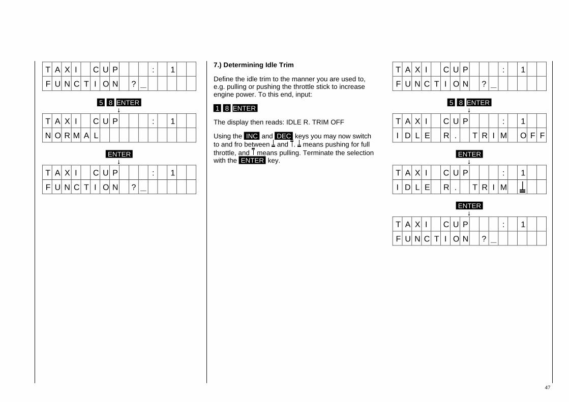
47
T A X I C U P : 1
F U N C T I O N ?
5 8 ENTER ↓↓
T A X I C U P : 1
N O R M A L
ENTER ↓↓
T A X I C U P : 1
F U N C T I O N ?
7.) Determining Idle Trim
Define the idle trim to the manner you are used to, e.g. pulling or pushing the throttle stick to increase engine power. To this end, input:
1 8 ENTER
The display then reads: IDLE R. TRIM OFF
Using the INC and DEC keys you may now switch to and fro between and . means pushing for full throttle, and means pulling. Terminate the selection with the ENTER key.
T A X I C U P : 1
F U N C T I O N ?
5 8 ENTER ↓↓
T A X I C U P : 1
I D L E R . T R I M O F F
ENTER ↓↓
T A X I C U P : 1
I D L E R . T R I M
ENTER ↓↓
T A X I C U P : 1
F U N C T I O N ?

Programming Examples for Fixed-Wing Models
48
8.) Copying Adjustments
All that’s been input so far may be considered as “pilot specific” programming, as these inputs depend on the habits of the pilot and are alike for all models (excepting the name of the model). In order not to have to input these settings for each model memory, you can now copy them first into the other model memories. To this end input:
9 4 ENTER 1 ENTER 2 ENTER ENTER
You have now copied the essential settings of model 1 onto model 2. Repeat the same procedure for the remaining models by:
9 4 ENTER 1 ENTER 3 ENTER ENTER 9 4 ENTER 1 ENTER 4 ENTER ENTER … 9 4 ENTER 1 ENTER 7 ENTER ENTER … ( 9 4 ENTER 1 ENTER 3 0 ENTER ENTER )
T A X I C U P : 1
F U N C T I O N ?
9 4 ENTER ↓↓
C O P Y : F R O M M O D E L
K E Y 1 - 7 O R + / - 1 ↓↓
C O P Y : F R O M M O D E L
T A X I C U P : 1
ENTER ↓↓
C O P Y : T O M O D E L
K E Y 1 - 7 O R + / - 2 ↓↓
C O P Y : T O M O D E L
N O N A M E : 2
ENTER ↓↓
C O P Y : 1 3
E N T E R K E Y e x e c
ENTER
9.) Modulation Mode
If a PCM receiver has been installed in your model you may skip this step. In the case of a PPM receiver just input:
9 5 ENTER INC ENTER
Doing this you have switched to PPM mode, The transmitter now requests you to turn it off so it can change over to PPM.
A reversion to PCM mode is performed in the same way.

49
T A X I C U P : 1
F U N C T I O N ?
9 5 ENTER ↓↓
T A X I C U P : 1
M O D U L A T I O N P C M
INC ↓↓
T A X I C U P : 1
M O D U L A T I O N P P M
ENTER ↓↓
T A X I C U P : 1
p o w e r s w o f f
Switch the power off, and then on again ↓↓
T A X I C U P : 1
9 . 6 V P P M
ENTER ↓↓
T A X I C U P : 1
F U N C T I O N ?
10.) Adjusting the Direction of Servo Rotation
For the ensuing adjustments you now require a model with a ready to operate installed radio set. The servos should be wired to the receiver as follows:
Channel 1 = Engine Throttle Channel 2 = Ailerons Channel 3 = Elevator Channel 4 = Rudder
Turn the transmitter and receiver on now and check the function of the control surfaces. Most likely one or other of the servos will be found to rotate in the wrong direction (it would be matter of sheer luck if not). To correct the direction of rotation of a servo moving in the wrong direction, call servo reversing code 11:
ENTER 1 1 ENTER
The display now indicates the direction of rotation of all servos. Correct the direction of rotation by entering the corresponding channel number so all control surfaces and the throttle move in the right direction. Terminate all input using the ENTER key.
T A X I C U P : 1
F U N C T I O N ?
1 1 ENTER ↓↓
R E V . S W
N O R M 1 2 3 4 5 6 7 8 9 2 ↓↓
R E V . S W 2
N O R M 1 4 5 6 7 8 9 3 ↓↓
R E V . S W 2 3
N O R M 1 4 5 6 7 8 9
ENTER ↓↓
T A X I C U P : 1
F U N C T I O N ?
Programming Examples for Fixed-Wing Models
50
11.) Adjusting Servo Throw
Normally one should choose the size of the control horn and servo arms so they provide approximately the required control surface throw. In this context you should remember: the relative size of the arm of a servo and the lever of a control horn determines the magnitude of the throw of the control surface. All control linkages introduce a certain amount of play, which can not be completely eliminated even when using top quality servos and working with ultimate precision, with the slop increasing with time. Everything should be done to reduce slop as much as possible. Here are some basic rules.
1. Keep control horns as large as possible as this helps minimise slop.
2. Slop will be greater the more acute or obtuse the angle formed by the linkage and control horn. Slop will be smallest when the linkage and horn for a right angle (90°).
3. Servo slop will make itself felt more the smaller the angular range the servo operates over.
When applying these fundamental rules the conclusion must be drawn that full servo throw should be used for the controls of a model, using the largest possible control horns, and that the required control throw should be achieved by adjusting the servo arm.
In practical operation, however, smaller and larger deviations from these ideal conditions have to be accepted, such as the selection of smaller control horns for visual reasons, the control surface linkages will have to be concealed in the gaps between surfaces, or the accommodation of large servo arms is not possible in the fuselage.
Fur such cases the PROFI-ULTRASOFT-Module provides the ability to adjust servo throw, with all the servos and each direction of operation being separately adjustable. To make this point perfectly clear: this possibility should be utilised only after you have mechanically optimised the linkages as far as possible in every case. At first glance, taking the easiest and simplest way of linking the control surfaces and performing adjustments via the transmitter options may appear to be a good solution, but in that case a lot of obtainable control precision will be lost. This, of course, is not limited to the control surfaces, but also applies to the throttle as well. Here again the linkage should be attached to the outermost hole of the carburettor lever and a servo arm chosen which will open the carburettor fully when the throttle stick is in the full throttle position, and will close the carburettor fully with the stick and trim fully pulled back. It is important that the servo is not mechanically restricted in it’s motion. If this can not be achieved mechanically the adjustments may then be optimised using the throw adjust (code 12). To achieve this, input:
1 2 ENTER
The select the control channel to be used for throw adjustments:
1 = Throttle 2 = Ailerons 3 = Elevator 4 = Rudder
Let us assume you wish to adjust servo throw for the throttle operation, press in this 1 case.
The display now indicates normal servo throw (100%). Shift the throttle stick to the full throttle position and adjust the carburettor with the aid of the INC and DEC keys so it will be fully open, but is not
hitting the mechanical stops. The display now shows the servo throw in % of normal servo throw.
Move the throttle to the idle position and set the trim slider for throttle all the way back against it’s stop, where the carburettor will be as closed as possible. The display now shows 100% again, since for this side of the servo throw (viewed from the centre) the normal value is still effective.
Throw is now adjusted using the INC and DEC keys so the carburettor is fully closed without hitting the mechanical stop. It is possible that an idle stop screw on the carburettor will have to be adjusted to permit the carburettor to fully close. You should now be able to adjust the RPM of the engine with the idle trim, and also stop the engine with the trim fully back.
In the same manner you’ll be able to adjust the throw of the control surfaces, if necessary asymmetrically, for example if the elevator at “full up” deflection blocks the rudder, and downward deflection must not be reduced. Call the elevator position and adjust deflection using the INC and DEC keys so that the rudder remains freely movable. Remember to take changes in elevator trim into account to ensure that fowling does not occur. Terminate the input by pressing the ENTER key.

51
T A X I C U P : 1
F U N C T I O N ?
1 2 ENTER ↓↓
T H R O W A D J U S T
p u s h c h k e y 1 - 9 1 ↓↓
T H R O W A D J U S T
1 c h + E N D 1 0 0 %
Stick in full Throttle position… INC / DEC ↓↓
T H R O W A D J U S T
1 c h + E N D 9 2 %
Stick and Trim in idle Throttle position ↓↓
T H R O W A D J U S T
1 c h - E N D 1 0 0 %
INC / DEC
T H R O W A D J U S T 1 c h + E N D 1 1 5 %
3 ↓↓
T H R O W A D J U S T
3 c h + E N D 1 0 0 %
INC … DEC … ENTER ↓↓
T A X I C U P : 1
F U N C T I O N ?
The model may be considered as now being essentially ready for flight, the vital adjustments having been performed. If you are a beginner you ought to be content with these adjustments and collect practical experience by now flying your model. Although it would not do any harm to try the other examples, you should keep in mind that the latter are “deluxe” options with the aid of which problems encountered when flying certain models can be solved. Flying certain manoeuvres can be made easier and/or advantages can be gained over other contestants in competition flying due to the simplified operation of the transmitter.
Bearing this in mind:
II. Further Examples
Let’s return to the last example in the preceding chapter. The full-span elevator of the tailplane when deflected upwards blocks the rudder mounted above it.
This had been avoided by reducing the upward servo throw correspondingly, also allowing for the possible upward trim movement. The reaction to elevator will be smoother now the down-elevator for the reduced throw is evenly distributed over the entire control throw range from neutral to hard over up. The different control reaction to “up” and “down” may be acceptable in some cases, but might not necessarily be so. The PROFI-ULTRASOFT-Module offers another option for such cases, namely throw reduction.
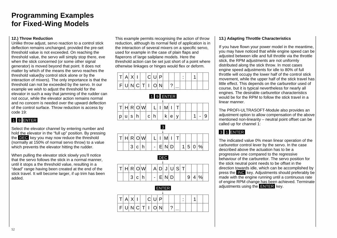
Programming Examples for Fixed-Wing Models
52
12.) Throw Reduction Unlike throw adjust, servo reaction to a control stick deflection remains unchanged, provided the pre-set threshold value is not exceeded. On reaching the threshold value, the servo will simply stop there, eve when the stick concerned (or some other signal generator) is moved beyond that point. It does not matter by which of the means the servo reaches the threshold value(by control stick alone or by the interaction of mixers). The only importance is that the threshold can not be exceeded by the servo. In our example we wish to adjust the threshold for the elevator in such a way that jamming of the rudder can not occur, while the elevator action remains normal and no concern is needed over the upward deflection of the control surface. Throw reduction is access by code 19:
1 9 ENTER
Select the elevator channel by entering number and hold the elevator in the “full up” position. By pressing the DEC key you may now reduce the threshold (normally at 150% of normal servo throw) to a value which prevents the elevator hitting the rudder.
When pulling the elevator stick slowly you’ll notice that the servo follows the stick in a normal manner, until it stops a the threshold value, resulting in a “dead” range having been created at the end of the stick travel. It will become larger, if up trim has been added.
This example permits recognising the action of throw reduction, although its normal field of application is in the interaction of several mixers on a specific servo, used for example in the case of plain flaps and flaperons of large sailplane models. Here the threshold action can be set just short of a point where otherwise linkages or hinges would flex or deform.
T A X I C U P : 1
F U N C T I O N ?
1 9 ENTER ↓↓
T H R O W L I M I T
p u s h c h k e y 1 - 9 3 ↓↓
T H R O W L I M I T
3 c h - E N D 1 5 0 %
DEC ↓↓
T H R O W A D J U S T
3 c h - E N D 9 4 %
ENTER ↓↓
T A X I C U P : 1
F U N C T I O N ?
13.) Adapting Throttle Characteristics
If you have flown your power model in the meantime, you may have noticed that while engine speed can be adjusted between idle and full throttle via the throttle stick, the RPM adjustments are not uniformly distributed along the stick throw. In most cases engine speed adjustments for idle to 80% of full throttle will occupy the lower half of the control stick movement, while the upper half of the stick travel has little effect. This depends on the carburettor used of course, but it is typical nevertheless for nearly all engines. The desirable carburettor characteristics would be for the RPM to follow the stick travel in a linear manner.
The PROFI-ULTRASOFT-Module also provides an adjustment option to allow compensation of the above mentioned non-linearity – neutral point offset can be called up for channel 1:
3 1 ENTER
The indicated value 0% mean linear operation of the carburettor control lever by the servo. In the case described above the actuation has to be a progressive one compared to the regressive behaviour of the carburettor. The servo position for the stick neutral point needs to be offset in the direction towards idle, which can be accomplished by press the INC key. Adjustments should preferably be made with the engine running until a continuous rate of engine RPM change has been achieved. Terminate adjustments using the ENTER key.
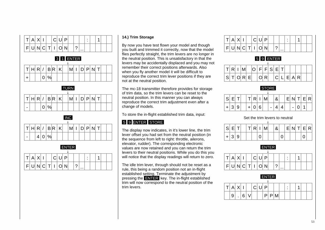
53
T A X I C U P : 1
F U N C T I O N ?
3 1 ENTER ↓↓
T H R / B R K M I D P N T
+ 0 %
TURN ↓↓
T H R / B R K M I D P N T
- 0 %
INC ↓↓
T H R / B R K M I D P N T
- 4 0 %
ENTER ↓↓
T A X I C U P : 1
F U N C T I O N ?
14.) Trim Storage
By now you have test flown your model and though you built and trimmed it correctly, now that the model flies perfectly straight, the trim levers are no longer in the neutral position. This is unsatisfactory in that the levers may be accidentally displaced and you may not remember their correct positions afterwards. Also when you fly another model it will be difficult to reproduce the correct trim lever positions if they are not at the neutral position.
The mc-18 transmitter therefore provides for storage of trim data, so the trim levers can be reset to the neutral position. In this manner you can always reproduce the correct trim adjustment even after a change of models.
To store the in-flight established trim data, input:
5 9 ENTER STORE
The display now indicates, in it’s lower line, the trim lever offset you had set from the neutral position (in the sequence from left to right: throttle, ailerons, elevator, rudder). The corresponding electronic values are now retained and you can return the trim levers to their neutral positions. While you do this you will notice that the display readings will return to zero.
The idle trim lever, through should not be reset as a rule, this being a random position not an in-flight established setting. Terminate the adjustment by pressing the ENTER key. The in-flight established trim will now correspond to the neutral position of the trim levers.
T A X I C U P : 1
F U N C T I O N ?
5 9 ENTER ↓↓
T R I M O F F S E T
S T O R E O R C L E A R
STORE ↓↓
S E T T R I M & E N T E R
+ 3 9 + 0 6 - 4 4 - 0 1
Set the trim levers to neutral ↓↓
S E T T R I M & E N T E R
+ 3 9 0 0 0
ENTER ↓↓
T A X I C U P : 1
F U N C T I O N ?
ENTER ↓↓
T A X I C U P : 1
9 . 6 V P P M
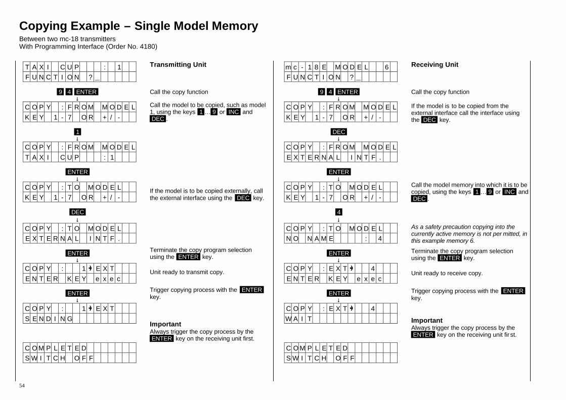
Copying Example – Single Model Memory Between two mc-18 transmitters With Programming Interface (Order No. 4180)
54
T A X I C U P : 1 F U N C T I O N ?
9 4 ENTER
↓↓ C O P Y : F R O M M O D E L K E Y 1 - 7 O R + / -
1 ↓↓
C O P Y : F R O M M O D E L T A X I C U P : 1
ENTER
↓↓ C O P Y : T O M O D E L K E Y 1 - 7 O R + / -
DEC
↓↓ C O P Y : T O M O D E L E X T E R N A L I N T F .
ENTER
↓↓ C O P Y : 1 E X T E N T E R K E Y e x e c
ENTER
↓↓ C O P Y : 1 E X T S E N D I N G
C O M P L E T E D S W I T C H O F F
Transmitting Unit
Call the copy function
Call the model to be copied, such as model 1, using the keys 1 … 9 or INC and DEC .
If the model is to be copied externally, call the external interface using the DEC key.
Terminate the copy program selection using the ENTER key.
Unit ready to transmit copy. Trigger copying process with the ENTER key. Important Always trigger the copy process by the ENTER key on the receiving unit first.
m c - 1 8 E M O D E L 6 F U N C T I O N ?
9 4 ENTER
↓↓ C O P Y : F R O M M O D E L K E Y 1 - 7 O R + / -
DEC
↓↓ C O P Y : F R O M M O D E L E X T E R N A L I N T F .
ENTER
↓↓ C O P Y : T O M O D E L K E Y 1 - 7 O R + / -
4 ↓↓
C O P Y : T O M O D E L N O N A M E : 4
ENTER
↓↓ C O P Y : E X T 4 E N T E R K E Y e x e c
ENTER
↓↓ C O P Y : E X T 4 W A I T
C O M P L E T E D S W I T C H O F F
Receiving Unit
Call the copy function If the model is to be copied from the external interface call the interface using the DEC key.
Call the model memory into which it is to be copied, using the keys 1 … 9 or INC and DEC .
As a safety precaution copying into the currently active memory is not per mitted, in this example memory 6.
Terminate the copy program selection using the ENTER key.
Unit ready to receive copy. Trigger copying process with the ENTER key.
Important Always trigger the copy process by the ENTER key on the receiving unit fir st.

Copying Example – All Model Memory Between two mc-18 transmitters With Programming Interface (Order No. 4180)
55
T A X I C U P : 1 F U N C T I O N ?
9 4 ENTER
↓↓ C O P Y : F R O M M O D E L K E Y 1 - 7 O R + / -
DEC DEC
↓↓ C O P Y : F R O M M O D E L T O T A L S T O R A G E
ENTER
↓↓ C O P Y : T O M O D E L K E Y 1 - 7 O R + / -
DEC
↓↓ C O P Y : T O M O D E L E X T E R N A L I N T F .
ENTER
↓↓ C O P Y : A L L E X T E N T E R K E Y e x e c
ENTER
↓↓ C O P Y : A L L E X T S E N D I N G
C O M P L E T E D S W I T C H O F F
Transmitting Unit
Call the copy function
Call all model memories by pressing the DEC key twice.
If the model is to be copied externally, call the external interface using the DEC key.
Terminate the copy program selection using the ENTER key.
Unit ready to transmit copy. Trigger copying process with the ENTER key.
Important Always trigger the copy process by the ENTER key on the receiving unit first.
m c - 1 8 E M O D E L 6 F U N C T I O N ?
9 4 ENTER
↓↓ C O P Y : F R O M M O D E L K E Y 1 - 7 O R + / -
DEC
↓↓ C O P Y : F R O M M O D E L E X T E R N A L I N T F .
ENTER
↓↓ C O P Y : T O M O D E L K E Y 1 - 7 O R + / -
DEC DEC
↓↓ C O P Y : T O M O D E L N O N A M E : 4
ENTER
↓↓ C O P Y : E X T A L L E N T E R K E Y e x e c
ENTER
↓↓ C O P Y : E X T A L L W A I T
C O M P L E T E D S W I T C H O F F
Receiving Unit
Call the copy function If the model is to be copied from the external interface call the interface using the DEC key.
Call all model memories by pressing the DEC key twice.
Terminate the copy program selection using the ENTER key.
Unit ready to receive copy. Trigger copying process with the ENTER key.
Important Always trigger the copy process by the ENTER key on the receiving unit first.
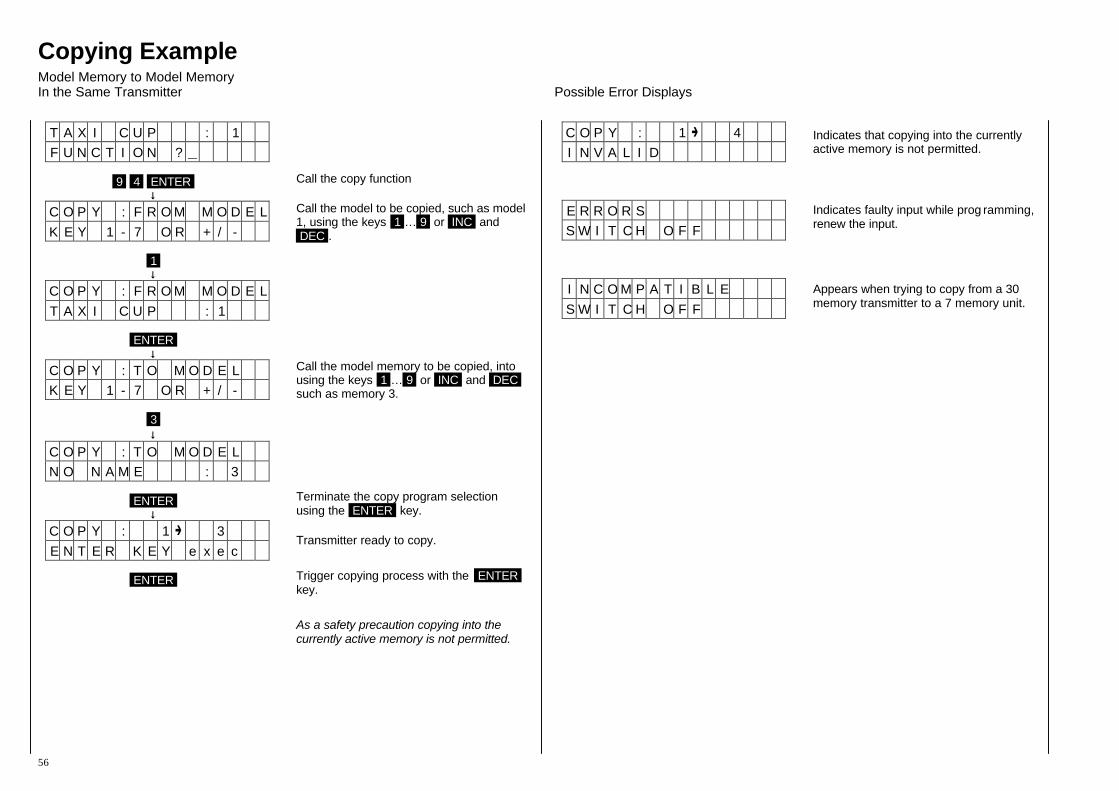
Copying Example Model Memory to Model Memory In the Same Transmitter Possible Error Displays
56
T A X I C U P : 1 F U N C T I O N ?
9 4 ENTER
↓↓ C O P Y : F R O M M O D E L K E Y 1 - 7 O R + / -
1 ↓↓
C O P Y : F R O M M O D E L T A X I C U P : 1
ENTER
↓↓ C O P Y : T O M O D E L K E Y 1 - 7 O R + / -
3 ↓↓
C O P Y : T O M O D E L N O N A M E : 3
ENTER
↓↓ C O P Y : 1 3 E N T E R K E Y e x e c
ENTER
Call the copy function
Call the model to be copied, such as model 1, using the keys 1 … 9 or INC and DEC .
Call the model memory to be copied, into using the keys 1 … 9 or INC and DEC such as memory 3.
Terminate the copy program selection using the ENTER key.
Transmitter ready to copy. Trigger copying process with the ENTER key. As a safety precaution copying into the currently active memory is not permitted.
C O P Y : 1 4 I N V A L I D
E R R O R S S W I T C H O F F
I N C O M P A T I B L E S W I T C H O F F
Indicates that copying into the currently active memory is not permitted.
Indicates faulty input while prog ramming, renew the input.
Appears when trying to copy from a 30 memory transmitter to a 7 memory unit.