Embed Size (px)
Citation preview

GraphiteVPX/XMC-PMC Carrier
Users Guide
www.connecttech.com
Document: CTIM-00460 Revision: 0.02
Page 1 of 19
Connect Tech Inc. 800-426-8979 | 519-836-1291
Date: 2016/10/27
GraphiteVPX/XMC-PMC Carrier
Connect Tech Inc. Tel: 519-836-1291
42 Arrow Road Toll: 800-426-8979 (North America only) Guelph, Ontario Fax: 519-836-4878 N1K 1S6 Email: [email protected] www.connecttech.com [email protected] CTIM-00460 Revision 0.02 2016/10/27
GraphiteVPX/XMC-PMC Carrier
Users Guide
www.connecttech.com
Document: CTIM-00460 Revision: 0.02
Page 2 of 19
Connect Tech Inc. 800-426-8979 | 519-836-1291
Date: 2016/10/27
Table of Contents
Table of Contents ................................................................................................................................... 2
Preface ................................................................................................................................................... 3
Disclaimer ....................................................................................................................................................... 3 Customer Support Overview ........................................................................................................................... 3 Contact Information ........................................................................................................................................ 3 Limited Product Warranty ............................................................................................................................... 4 Copyright Notice ............................................................................................................................................. 4 Trademark Acknowledgment .......................................................................................................................... 4 ESD Warning .................................................................................................................................................. 5
Revision History .................................................................................................................................... 5
Introduction........................................................................................................................................... 6
Feature List ........................................................................................................................................... 6
Product Overview .................................................................................................................................. 8
Block Diagram ................................................................................................................................................ 8 Ordering Part Numbers ................................................................................................................................... 9 Mezzanine Connector Locations (VPG10x) .................................................................................................. 10 Connector Summary ...................................................................................................................................... 10 Backplane Configuration Header (J2) ........................................................................................................... 11
Detailed Pinouts and Descriptions ........................................................................................................ 13
I/O Configuration Options: ........................................................................................................................... 13
System Management Interface ............................................................................................................. 14
Addressing the I2C Slave Interface (I2C Mux) ............................................................................................. 14 Writing to the I2C Slave Interface................................................................................................................. 15 Reading from the I2C Slave Interface ........................................................................................................... 15
Thermal Details ................................................................................................................................... 16
Thermal Parameters ....................................................................................................................................... 16
Current Consumption Details .............................................................................................................. 17
Mechanical Details ............................................................................................................................... 18
3D STEP Models ........................................................................................................................................... 18 Top and Bottom Photos ................................................................................................................................. 19
GraphiteVPX/XMC-PMC Carrier
Users Guide
www.connecttech.com
Document: CTIM-00460 Revision: 0.02
Page 3 of 19
Connect Tech Inc. 800-426-8979 | 519-836-1291
Date: 2016/10/27
Preface
Disclaimer The information contained within this user’s guide, including but not limited to any product specification, is
subject to change without notice.
Connect Tech assumes no liability for any damages incurred directly or indirectly from any technical or
typographical errors or omissions contained herein or for discrepancies between the product and the user’s
guide.
Customer Support Overview If you experience difficulties after reading the manual and/or using the product, contact the Connect Tech
reseller from which you purchased the product. In most cases the reseller can help you with product installation
and difficulties.
In the event that the reseller is unable to resolve your problem, our highly qualified support staff can assist you.
Our support section is available 24 hours a day, 7 days a week on our website at:
www.connecttech.com/sub/support/support.asp. See the contact information section below for more
information on how to contact us directly. Our technical support is always free.
Contact Information
Mail/Courier Connect Tech Inc.
Technical Support
42 Arrow Road
Guelph, Ontario
Canada N1K 1S6
Email/Internet
www.connecttech.com
Note:
Please go to the Download Zone or the Knowledge Database in the Support Center on the Connect Tech
website for product manuals, installation guides, device driver software and technical tips.
Submit your technical support questions to our customer support engineers via the Support Center on the
Connect Tech website.
Telephone/Facsimile
Technical Support representatives are ready to answer your call Monday through Friday, from 8:30 a.m. to
5:00 p.m. Eastern Standard Time. Our numbers for calls are: Toll Free: 800-426-8979 (North America only)
Telephone: 519-836-1291 (Live assistance available 8:30 a.m. to 5:00 p.m. EST, Monday to Friday)
Facsimile: 519-836-4878 (on-line 24 hours)
GraphiteVPX/XMC-PMC Carrier
Users Guide
www.connecttech.com
Document: CTIM-00460 Revision: 0.02
Page 4 of 19
Connect Tech Inc. 800-426-8979 | 519-836-1291
Date: 2016/10/27
Limited Product Warranty
Connect Tech Inc. provides a 1 year Warranty for the 3U GraphiteVPX/XMC-PMC Carrier. Should this
product, in Connect Tech Inc.'s opinion, fail to be in good working order during the warranty period, Connect
Tech Inc. will, at its option, repair or replace this product at no charge, provided that the product has not been
subjected to abuse, misuse, accident, disaster or non-Connect Tech Inc. authorized modification or repair.
You may obtain warranty service by delivering this product to an authorized Connect Tech Inc. business
partner or to Connect Tech Inc. along with proof of purchase. Product returned to Connect Tech Inc. must be
pre-authorized by Connect Tech Inc. with an RMA (Return Material Authorization) number marked on the
outside of the package and sent prepaid, insured and packaged for safe shipment. Connect Tech Inc. will
return this product by prepaid ground shipment service.
The Connect Tech Inc. Limited Warranty is only valid over the serviceable life of the product. This is defined
as the period during which all components are available. Should the product prove to be irreparable, Connect
Tech Inc. reserves the right to substitute an equivalent product if available or to retract the Warranty if no
replacement is available.
The above warranty is the only warranty authorized by Connect Tech Inc. Under no circumstances will
Connect Tech Inc. be liable in any way for any damages, including any lost profits, lost savings or other
incidental or consequential damages arising out of the use of, or inability to use, such product.
Copyright Notice
The information contained in this document is subject to change without notice. Connect Tech Inc. shall not
be liable for errors contained herein or for incidental consequential damages in connection with the furnishing,
performance, or use of this material. This document contains proprietary information that is protected by
copyright. All rights are reserved. No part of this document may be photocopied, reproduced, or translated to
another language without the prior written consent of Connect Tech, Inc.
Copyright 2016 by Connect Tech, Inc.
Trademark Acknowledgment
Connect Tech, Inc. acknowledges all trademarks, registered trademarks and/or copyrights referred to in this
document as the property of their respective owners. Not listing all possible trademarks or copyright
acknowledgments does not constitute a lack of acknowledgment to the rightful owners of the trademarks and
copyrights mentioned in this document.
GraphiteVPX/XMC-PMC Carrier
Users Guide
www.connecttech.com
Document: CTIM-00460 Revision: 0.02
Page 5 of 19
Connect Tech Inc. 800-426-8979 | 519-836-1291
Date: 2016/10/27
ESD Warning
Electronic components and circuits are sensitive to
Electrostatic Discharge (ESD). When handling any circuit
board assemblies including Connect Tech VPX
assemblies, it is recommended that ESD safety
precautions be observed. ESD safe best practices include,
but are not limited to:
Leaving circuit boards in their antistatic packaging
until they are ready to be installed.
Using a grounded wrist strap when handling circuit
boards, at a minimum you should touch a grounded
metal object to dissipate any static charge that may be
present on you.
Only handling circuit boards in ESD safe areas, which
may include ESD floor and table mats, wrist strap
stations and ESD safe lab coats.
Avoiding handling circuit boards in carpeted areas.
Try to handle the board by the edges, avoiding contact
with components.
Revision History Revision Date Changes
0.00 23/03/2016 Initial Release
0.01 17/06/2016 Updates for clarity, modified default XMC VPWR to 5V.
0.02 27/10/2016 Removed detailed pinouts, updated card edge temperatures.

GraphiteVPX/XMC-PMC Carrier
Users Guide
www.connecttech.com
Document: CTIM-00460 Revision: 0.02
Page 6 of 19
Connect Tech Inc. 800-426-8979 | 519-836-1291
Date: 2016/10/27
Introduction
Connect Tech’s 3U GraphiteVPX/XMC-PMC is a VITA 65 compliant 3U peripheral carrier card that brings
PCIe Gen 3.0 capable features to a mezzanine carrier. Complete with a x8 Gen 3 PCIe capable VITA 42 XMC
interface for all the newest, high-end mezzanine cards, as well as a 64-bit 133MHz PCI-X capable interface for
use with all of your legacy PCI based PMC mezzanines.
Feature List
Feature Description
XMC Mezzanine Support
(VITA 42.3)
VITA 42.3 compliant x8 lane PCIe Gen 3.0 bus interface on Pn5.
XMC I/O from Pn6 or I/O from Pn4
Both options are available.
PMC Mezzanine Support
(IEEE 1386)
IEEE-1386 and VITA-20 compliant 64 bit/133MHz PCI-X interface. Backwards compatible
with 32bit/33MHz PCI. 3.3V VIO only, PMC PCI Bus I/O is NOT 5V tolerant.
PMC I/O from Pn4
Bus Interface (Backplane)
One x8 lane or Two x4 lane PCIe Gen 3.0 Data Plane ports (backwards compatible with PCIe
Gen 1 and Gen 2 systems).
Designed for use in VPX PCIe systems that support separate clock architectures (a reference
PCIe clock is NOT required on the backplane for this card).
Mezzanine I/O support
VITA 46.9 compliant I/O mapping:
PMC – 64 I/O mapped as P64s
Or
XMC – 20 diff pair I/O and 38 single ended I/O mapped as X12d+X8d+X38s *see pinout for details*
Backplane Port Options
Select from: 1) One 8 Lane PCIe or Two 4 Lane PCIe – Data Plane only
2) If two 4 lane PCIe are selected, two upstream port selection options are available to
allow for ease of use in the backplane slots, and the remaining downstream port is available for another peripheral.
3) If two 4 lane PCIe selected, a Non-Transparent port option is available
Temperature Sensors
4 onboard TMP101 I2C accessible card edge temperature sensors for system monitoring.
Indicator LEDs (Front edge)
BP_OK (Backplane power ok), PCIe0, PCIe1, PCIe2 (port link and speed indicators), PERR
(PCIe Fatal Error)
Standalone Operation
No, an upstream PCIe host board is required.
GraphiteVPX/XMC-PMC Carrier
Users Guide
www.connecttech.com
Document: CTIM-00460 Revision: 0.02
Page 7 of 19
Connect Tech Inc. 800-426-8979 | 519-836-1291
Date: 2016/10/27
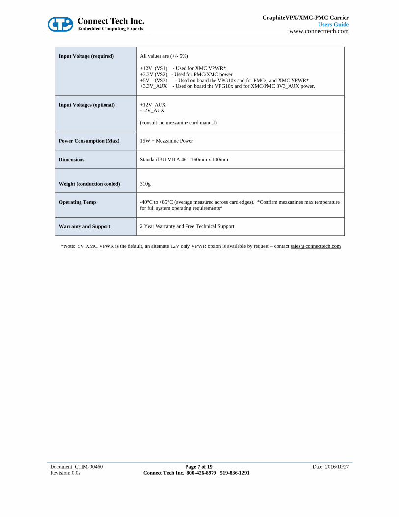
Input Voltage (required)
All values are (+/- 5%)
+12V (VS1) - Used for XMC VPWR*
+3.3V (VS2) - Used for PMC/XMC power +5V (VS3) - Used on board the VPG10x and for PMCs, and XMC VPWR*
+3.3V_AUX - Used on board the VPG10x and for XMC/PMC 3V3_AUX power.
Input Voltages (optional)
+12V_AUX
-12V_AUX
(consult the mezzanine card manual)
Power Consumption (Max)
15W + Mezzanine Power
Dimensions
Standard 3U VITA 46 - 160mm x 100mm
Weight (conduction cooled)
310g
Operating Temp
-40°C to +85°C (average measured across card edges). *Confirm mezzanines max temperature for full system operating requirements*
Warranty and Support
2 Year Warranty and Free Technical Support
*Note: 5V XMC VPWR is the default, an alternate 12V only VPWR option is available by request – contact [email protected]

GraphiteVPX/XMC-PMC Carrier
Users Guide
www.connecttech.com
Document: CTIM-00460 Revision: 0.02
Page 8 of 19
Connect Tech Inc. 800-426-8979 | 519-836-1291
Date: 2016/10/27
Product Overview
Block Diagram

GraphiteVPX/XMC-PMC Carrier
Users Guide
www.connecttech.com
Document: CTIM-00460 Revision: 0.02
Page 9 of 19
Connect Tech Inc. 800-426-8979 | 519-836-1291
Date: 2016/10/27
Ordering Part Numbers
Part
Number Photo Description
VPG101
Conduction Cooled XMC/PMC
Carrier with
XMC I/O (X12d+X8d+X38s)
VPG102
Conduction Cooled XMC/PMC
Carrier with
PMC I/O (P64s)*
*use this version for XMCs with legacy Pn4 I/O
GraphiteVPX/XMC-PMC Carrier
Users Guide
www.connecttech.com
Document: CTIM-00460 Revision: 0.02
Page 10 of 19
Connect Tech Inc. 800-426-8979 | 519-836-1291
Date: 2016/10/27
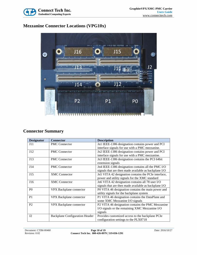
Mezzanine Connector Locations (VPG10x)
Connector Summary
Designator Connector Description
J11 PMC Connector Jn1 IEEE-1386 designation contains power and PCI
interface signals for use with a PMC mezzanine.
J12 PMC Connector Jn2 IEEE-1386 designation contains power and PCI
interface signals for use with a PMC mezzanine.
J13 PMC Connector Jn3 IEEE-1386 designation contains the PCI 64bit
extension signals
J14 PMC Connector Jn4 IEEE-1386 designation contains all the PMC I/O
signals that are then made available as backplane I/O
J15 XMC Connector Jn5 VITA 42 designation contains the PCIe interface,
power and utility signals for the XMC standard
J16 XMC Connector Jn6 VITA 42 designation contains all 78 user I/O
signals that are then made available as backplane I/O
P0 VPX Backplane connector P0 VITA 46 designation contains the main power and
utility signals for the backplane system
P1 VPX Backplane connector P1 VITA 46 designation contains the DataPlane and
some XMC Mezzanine I/O signals
P2 VPX Backplane connector P2 VITA 46 designation contains the PMC Mezzanine
I/O signals or the remaining XMC Mezzanine I/O
signals
J2 Backplane Configuration Header Provides customized access to the backplane PCIe
configuration settings to the PLX8718
GraphiteVPX/XMC-PMC Carrier
Users Guide
www.connecttech.com
Document: CTIM-00460 Revision: 0.02
Page 11 of 19
Connect Tech Inc. 800-426-8979 | 519-836-1291
Date: 2016/10/27
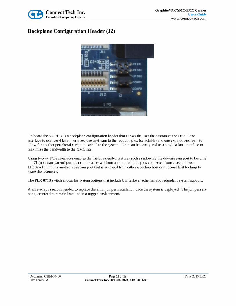
Backplane Configuration Header (J2)
On board the VGP10x is a backplane configuration header that allows the user the customize the Data Plane
interface to use two 4 lane interfaces, one upstream to the root complex (selectable) and one extra downstream to
allow for another peripheral card to be added to the system. Or it can be configured as a single 8 lane interface to
maximize the bandwidth to the XMC site.
Using two 4x PCIe interfaces enables the use of extended features such as allowing the downstream port to become
an NT (non-transparent) port that can be accessed from another root complex connected from a second host.
Effectively creating another upstream port that is accessed from either a backup host or a second host looking to
share the resources.
The PLX 8718 switch allows for system options that include bus failover schemes and redundant system support.
A wire-wrap is recommended to replace the 2mm jumper installation once the system is deployed. The jumpers are
not guaranteed to remain installed in a rugged environment.

GraphiteVPX/XMC-PMC Carrier
Users Guide
www.connecttech.com
Document: CTIM-00460 Revision: 0.02
Page 12 of 19
Connect Tech Inc. 800-426-8979 | 519-836-1291
Date: 2016/10/27
Jumper Settings Summary:
Jumper Name Description Default
CONF0
PCIe Backplane port configuration selection:
Two 4 lane or One 8 lane option.
Selection Jumpers
Two 4 Lane Ports
One 8 lane Port
CONF0 installed open
CONF1 open installed
*All others are reserved
CONF1 installed
CONF1
UP SEL
PCIe Backplane upstream port selection
Open = Port 1, Installed = Port 2
Nothing installed
NT SEL
PCIe Backplane Non-Transparent port selection (4 lane mode only)
Nothing installed
NT EN
Enable Non-Transparent port connection (4 lane mode only)
Nothing installed
GraphiteVPX/XMC-PMC Carrier
Users Guide
www.connecttech.com
Document: CTIM-00460 Revision: 0.02
Page 13 of 19
Connect Tech Inc. 800-426-8979 | 519-836-1291
Date: 2016/10/27
Detailed Pinouts and Descriptions
Full pinout details are available only under an NDA (Non-Disclosure Agreement). Please contact sales at
Connect Tech Inc. for further information.
1-800-426-8979
http://www.connecttech.com
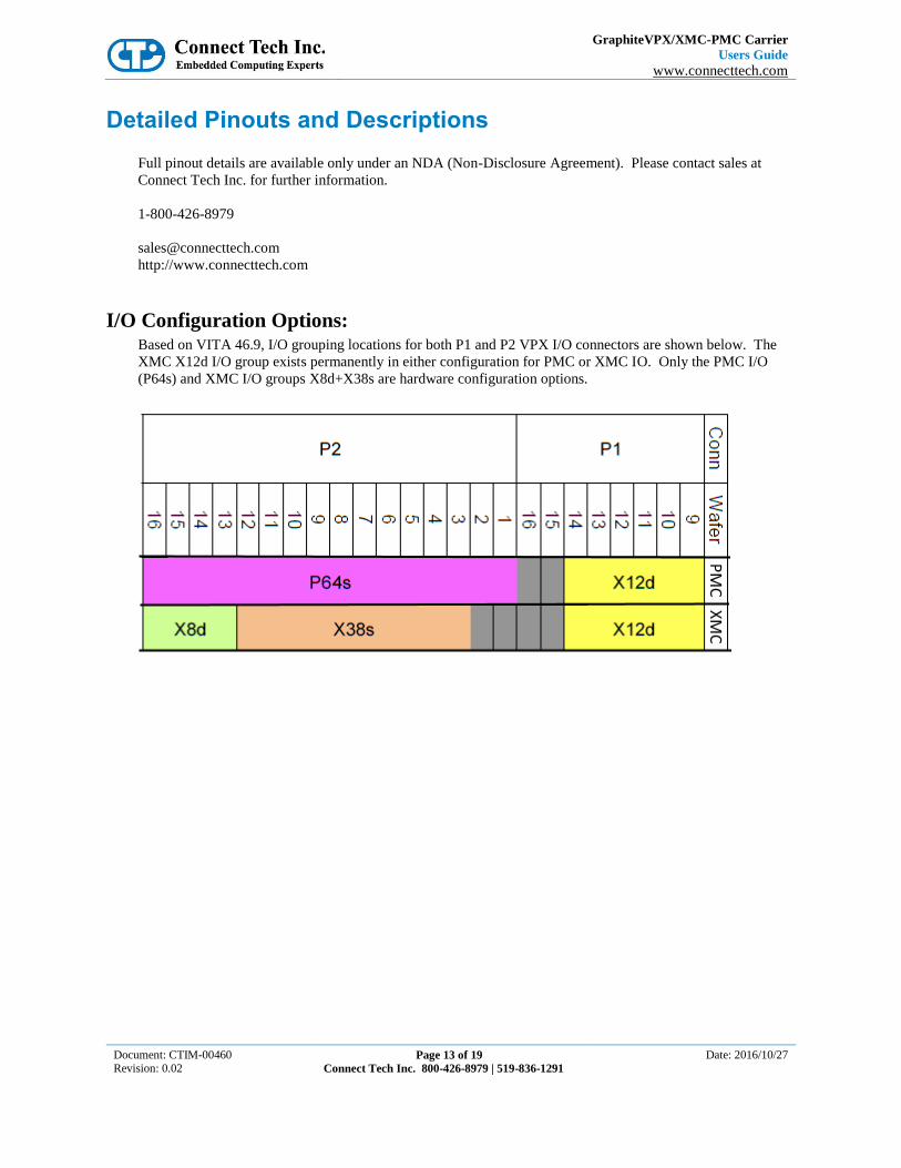
I/O Configuration Options: Based on VITA 46.9, I/O grouping locations for both P1 and P2 VPX I/O connectors are shown below. The
XMC X12d I/O group exists permanently in either configuration for PMC or XMC IO. Only the PMC I/O
(P64s) and XMC I/O groups X8d+X38s are hardware configuration options.
GraphiteVPX/XMC-PMC Carrier
Users Guide
www.connecttech.com
Document: CTIM-00460 Revision: 0.02
Page 14 of 19
Connect Tech Inc. 800-426-8979 | 519-836-1291
Date: 2016/10/27
System Management Interface
The GraphiteVPX/XMC-PMC supports an I2C slave interface on the SM0 (SCL) and SM1 (SDA) signals
connected to the VPX backplane. The I2C address of this interface is determined by the Geographic Address
lines GA0#, GA1#, and GA2#. This interface operates at 100 KHz.
There are 10K OHM pull-ups to the +3.3V_AUX supply on the I2C slave interface on SM0 and SM1.
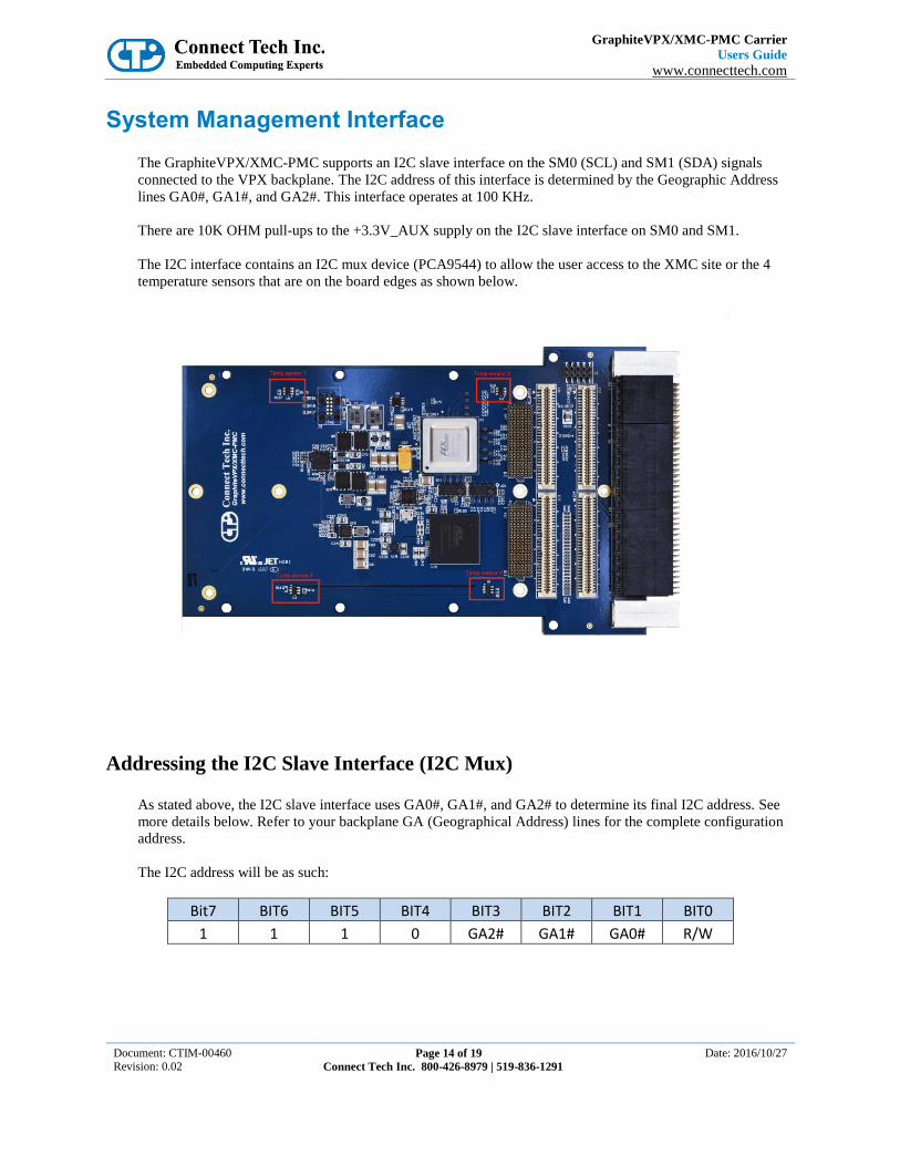
The I2C interface contains an I2C mux device (PCA9544) to allow the user access to the XMC site or the 4
temperature sensors that are on the board edges as shown below.
Addressing the I2C Slave Interface (I2C Mux)
As stated above, the I2C slave interface uses GA0#, GA1#, and GA2# to determine its final I2C address. See
more details below. Refer to your backplane GA (Geographical Address) lines for the complete configuration
address.
The I2C address will be as such:
Bit7 BIT6 BIT5 BIT4 BIT3 BIT2 BIT1 BIT0
1 1 1 0 GA2# GA1# GA0# R/W
GraphiteVPX/XMC-PMC Carrier
Users Guide
www.connecttech.com
Document: CTIM-00460 Revision: 0.02
Page 15 of 19
Connect Tech Inc. 800-426-8979 | 519-836-1291
Date: 2016/10/27
Writing to the I2C Slave Interface
Refer to the NXP PCA9544 for access details.
The I2C multiplexor is like a ‘gate’ to open an on board I2C bus to access one of three card side busses:
1) Bus 0 – is currently not accessible
2) Bus 1 – is a direct link with XMC sites I2C system interface
3) Bus 2 – is a link to 2 TMP101 temperature sensors on the top edge (device 1 and 2)
4) Bus 3 – is a link to 2 TMP101 temperature sensors on the bottom edge (device 3 and 4)
*Refer to the TI TMP101 datasheet for access and setup of ALERT pin interrupt to the PCA9544. A Thermal
Alert LED is accessible on the solder side of the card if a visual indicator is required.
Reading from the I2C Slave Interface
When reading from the I2C slave interface, the last value stored in the command register by a write operation
is used to determine which command to respond to. To change the command for a read operation, a new
command must be written to the command register. This is accomplished by issuing an I2C slave address byte
with the R/W# bit LOW, followed by the command byte. The master can then generate a START condition
and send the I2C slave address bute with the R/W# bit HIGH to initiate a read command. If repeated reads
from the same register are required it is not necessary to continually send the command byte. The slave I2C
interface will remember the original command value until it is changed by the next write operation.
Example XML code to open the I2C mux and access the 4 temperature sensors using the Totalphase
Aardvark™ USB to I2C controller can be provided by request.
GraphiteVPX/XMC-PMC Carrier
Users Guide
www.connecttech.com
Document: CTIM-00460 Revision: 0.02
Page 16 of 19
Connect Tech Inc. 800-426-8979 | 519-836-1291
Date: 2016/10/27
Thermal Details
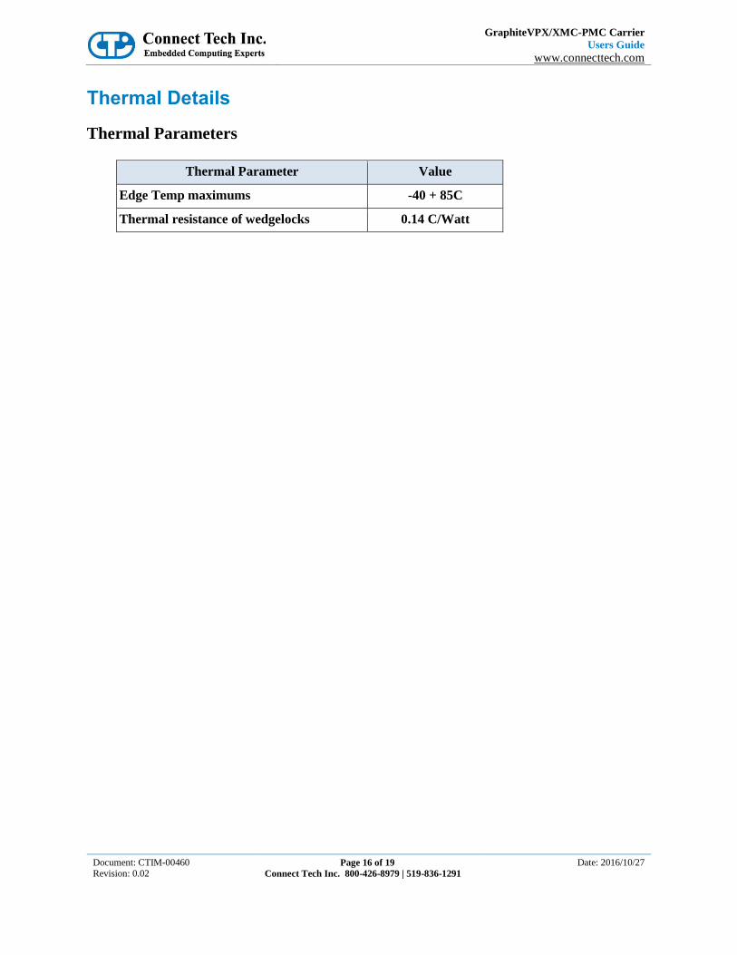
Thermal Parameters
Thermal Parameter Value
Edge Temp maximums -40 + 85C
Thermal resistance of wedgelocks 0.14 C/Watt

GraphiteVPX/XMC-PMC Carrier
Users Guide
www.connecttech.com
Document: CTIM-00460 Revision: 0.02
Page 17 of 19
Connect Tech Inc. 800-426-8979 | 519-836-1291
Date: 2016/10/27
Current Consumption Details
Below are current consumption details for the 3U GraphiteVPX XMC-PMC Carrier only, this data does not
include the mezzanine (XMC or PMC) power. Refer to the mezzanine datasheets for additional information.
Input Power:
Power Max Current (A) Power (W)
+12V (VS1)
0 (XMC VPWR only)
0 (XMC VPWR only)
+3.3V (VS2)
0 (XMC or PMC only)
0 (XMC or PMC only)
+5V (VS3)
2.9A + PMC or XMC
14.5W + PMC or XMC
+3.3V_AUX
100mA + XMC
330mW + XMC
+12V_AUX
0 (XMC or PMC only)
0 (XMC or PMC only)
-12V_AUX
0 (XMC or PMC only)
0 (XMC or PMC only)

GraphiteVPX/XMC-PMC Carrier
Users Guide
www.connecttech.com
Document: CTIM-00460 Revision: 0.02
Page 18 of 19
Connect Tech Inc. 800-426-8979 | 519-836-1291
Date: 2016/10/27
Mechanical Details
3D STEP Models A complete 3D STEP Model file for the Conduction Cooled GraphiteVPX/XMC-PMC is available at:
http://www.connecttech.com/
The model contains mount points and thermal interface locations for a mounting a standard PMC or XMC
mounting with 10mm standoffs with both primary and secondary cooling interfaces. The Aluminum thermal
frame is anodized but is connected to CGND or Chassis Ground through the mounting holes. The PMC
standoff mounts are floating and are not connected to either CGND or Digital GND (ground).
CGND (Chassis Ground) is connected to Digital GND at one point through a 5Meg Ohm resistance, to allow
for the slow removal or drain of any stray charge.
** Please note that a ground loop is possible if the mezzanine connects any of the thermal interface mounting
screws to Digital Ground (GND) **

GraphiteVPX/XMC-PMC Carrier
Users Guide
www.connecttech.com
Document: CTIM-00460 Revision: 0.02
Page 19 of 19
Connect Tech Inc. 800-426-8979 | 519-836-1291
Date: 2016/10/27
Top and Bottom Photos