Embed Size (px)
DESCRIPTION
graphite, bearing, installation, disassembly, lubrication, materials, various,
Citation preview
Bearing andSeal TechnologyBearings
Schunk TribologieGroup
Table of contents
Characteristic properties for use as a bearing material
Bearing design
Installation
Bearing clearance
Counterpart materials and their surface quality
Loading capacity
Fields of application and material recommendations
Page 3
Page 3
Page 4
Pages 6-7
Pages 6-7
Pages 8-10
Page 11
Characteristic properties for use
... as a bearing material
Carbon and graphite materials
exhibit the following characteristic
properties:
• excellent sliding and dry
running properties, low
coefficient of friction,
• good thermal conductivity,
• high chemical resistance,
• outstanding resistance to
thermal shock,
• excellent dimensional
stability,
• high fatigue resistance.
Due to these properties, carbon and
graphite bearings are used in many
applications, such as high and low
temperature technology, chemical
and petrochemical industries, food,
pharmaceutical and cosmetic
industries, automotive applications,
and nuclear reactor technology.
Information on the production and
physical properties of Schunk carbon
and graphite materials is given in
other publications.
This also applies predominantly
to wet running radial bearings,
though these can be provided with
spiral or axial grooves in the bore.
Facial grooves, however, are
recommended for fluid lubricated
axial carbon bearings (flanged
bearings). Recommendations on
the design of the facial grooves
may be supplied on request.
It is possible to manufacture self-
aligning spherical carbon bearings
but this involves a correspondingly
high effort in material and labour,
since the bearings must be machined
from cylindrical blanks. Partial
pressing-to-size can be considered
for larger quantities provided that
no close spherical tolerances are
required. For further information
please refer to our brochure 30.20
("Bearing and Seal Technology:
General information; properties;
use as sliding material; design
recommendations").
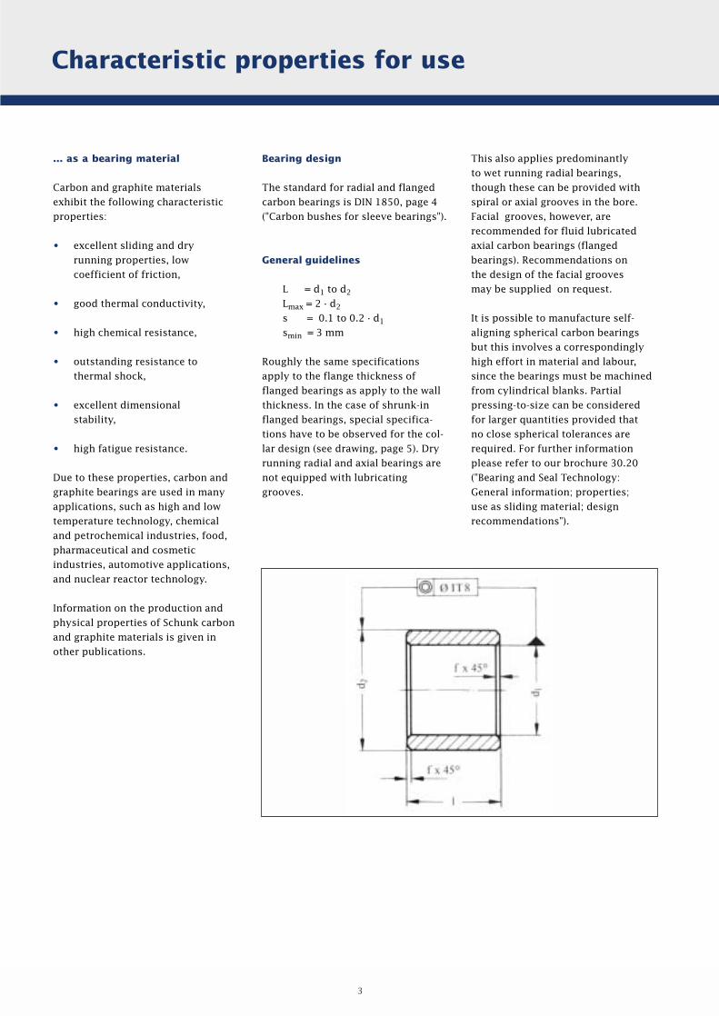
Bearing design
The standard for radial and flanged
carbon bearings is DIN 1850, page 4
("Carbon bushes for sleeve bearings").
General guidelines
L = d1 to d2
Lmax = 2 · d2
s = 0.1 to 0.2 · d1
smin = 3 mm
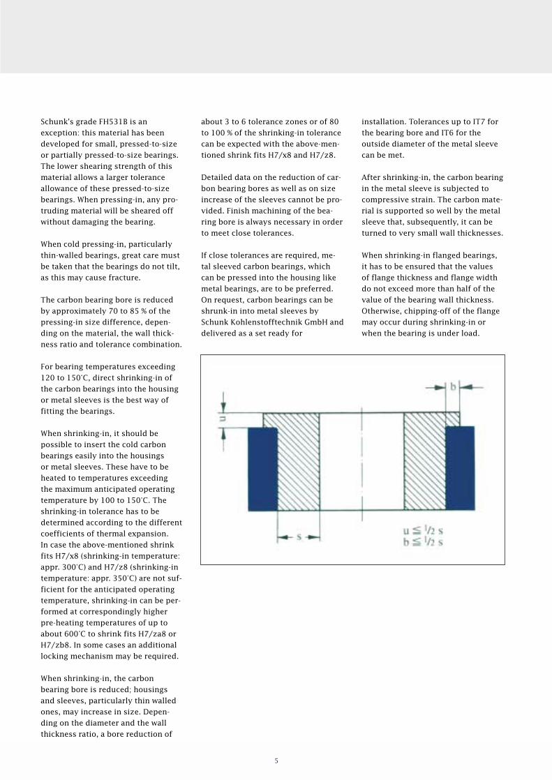
Roughly the same specifications
apply to the flange thickness of
flanged bearings as apply to the wall
thickness. In the case of shrunk-in
flanged bearings, special specifica-
tions have to be observed for the col-
lar design (see drawing, page 5). Dry
running radial and axial bearings are
not equipped with lubricating
grooves.
3
Installation
Pressing-in
Recommended tolerance zones
before cold pressing-in:
Inside diameter d1: F7 - E7
Outside diameter d2: s6
Housing bore for
carbon bearing: H7
This results in a tolerance of
H7 to H8 for the inside diameter
d1 after pressing-in.
For cold pressing-in, a pressing-in
mandrel should be used with a
diameter of about 3 tolerance zones
below the bore tolerance of the
carbon bearing in its delivered state.
Additionally, the mandrel's shoulder
should press onto the entire bearing
face.
Shrinking-in
Recommended tolerance zones
before hot shrinking-in:
Inside diameter d1: D8
Outside diameter d2: x8 to z8
Housing bore for
carbon bearing: H7
Shrinking-in
temperature: 300°C - 350°C
This results in a tolerance of H9
for the inside diameter d1 after
shrinking-in. Finish reaming is
recommended subsequent to
shrinking-in for staying exactly
within the tolerances.
When installing carbon bearings,
special attention has to be paid to
the lower coefficient of thermal
expansion of carbon and graphite
materials compared to that of
metals. Additionally, the lower
strength and brittleness of carbon
materials have to be considered.
Therefore, carbon bearings should
not be installed without support.
The normal press and shrink fits for
metals result in good fits having a
relatively low maximum temperature
operating limit, when using carbon
materials with metals, due to the
relatively low thermal expansion of
the carbon materials. Therefore, a
cold press fit of carbon bearings in
steel housings according to H7/s6
can only be used up to maximum bea-
ring temperatures of approximately
120 - 150 °C.
The maximum allowable tempe-
rature is correspondingly lower
for housings or sleeves made of
materials possessing a higher
coefficient of thermal expansion
than steel.
A tolerance allowance on the
diameter exceeding H7/s6 is not
recommended for cold pressing-in
of carbon bearings, except for
plastic housings or sleeves, due to
the likely occurrence of shearing.
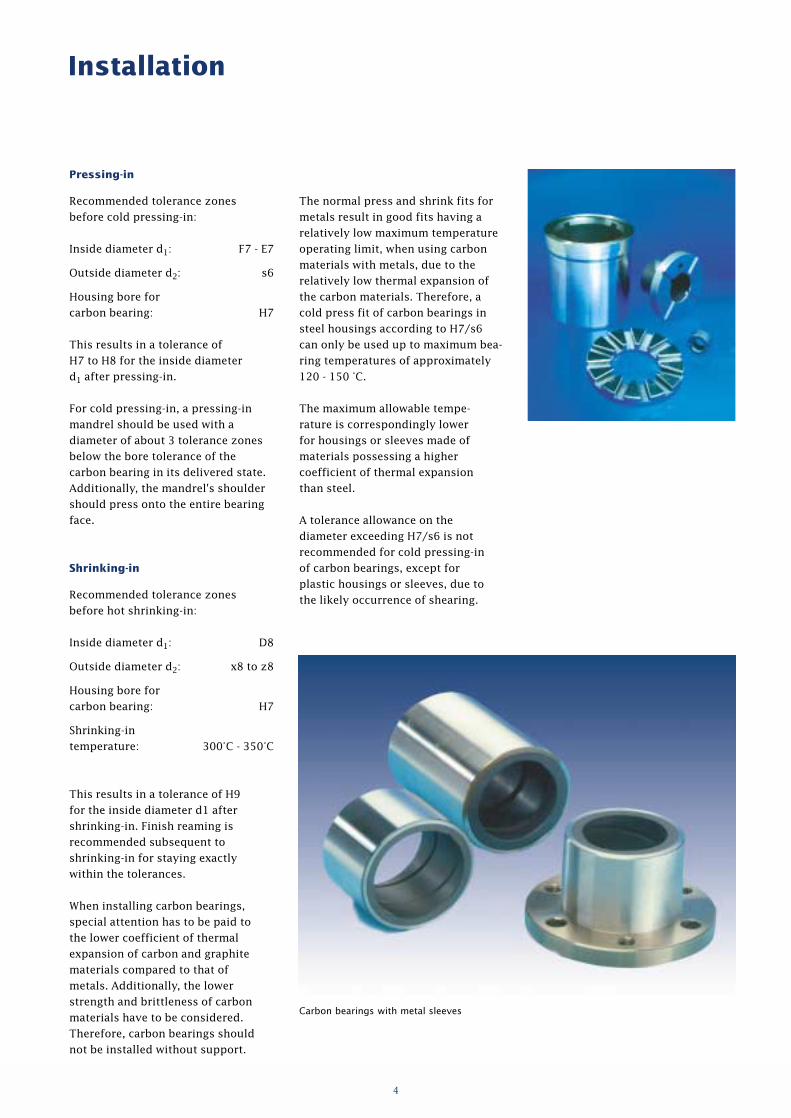
Carbon bearings with metal sleeves
4
Schunk's grade FH531B is an
exception: this material has been
developed for small, pressed-to-size
or partially pressed-to-size bearings.
The lower shearing strength of this
material allows a larger tolerance
allowance of these pressed-to-size
bearings. When pressing-in, any pro-
truding material will be sheared off
without damaging the bearing.
When cold pressing-in, particularly
thin-walled bearings, great care must
be taken that the bearings do not tilt,
as this may cause fracture.
The carbon bearing bore is reduced
by approximately 70 to 85 % of the
pressing-in size difference, depen-
ding on the material, the wall thick-
ness ratio and tolerance combination.
For bearing temperatures exceeding
120 to 150°C, direct shrinking-in of
the carbon bearings into the housing
or metal sleeves is the best way of
fitting the bearings.
When shrinking-in, it should be
possible to insert the cold carbon
bearings easily into the housings
or metal sleeves. These have to be
heated to temperatures exceeding
the maximum anticipated operating
temperature by 100 to 150°C. The
shrinking-in tolerance has to be
determined according to the different
coefficients of thermal expansion.
In case the above-mentioned shrink
fits H7/x8 (shrinking-in temperature:
appr. 300°C) and H7/z8 (shrinking-in
temperature: appr. 350°C) are not suf-
ficient for the anticipated operating
temperature, shrinking-in can be per-
formed at correspondingly higher
pre-heating temperatures of up to
about 600°C to shrink fits H7/za8 or
H7/zb8. In some cases an additional
locking mechanism may be required.
When shrinking-in, the carbon
bearing bore is reduced; housings
and sleeves, particularly thin walled
ones, may increase in size. Depen-
ding on the diameter and the wall
thickness ratio, a bore reduction of
installation. Tolerances up to IT7 for
the bearing bore and IT6 for the
outside diameter of the metal sleeve
can be met.
After shrinking-in, the carbon bearing
in the metal sleeve is subjected to
compressive strain. The carbon mate-
rial is supported so well by the metal
sleeve that, subsequently, it can be
turned to very small wall thicknesses.
When shrinking-in flanged bearings,
it has to be ensured that the values
of flange thickness and flange width
do not exceed more than half of the
value of the bearing wall thickness.
Otherwise, chipping-off of the flange
may occur during shrinking-in or
when the bearing is under load.
about 3 to 6 tolerance zones or of 80
to 100 % of the shrinking-in tolerance
can be expected with the above-men-
tioned shrink fits H7/x8 and H7/z8.
Detailed data on the reduction of car-
bon bearing bores as well as on size
increase of the sleeves cannot be pro-
vided. Finish machining of the bea-
ring bore is always necessary in order
to meet close tolerances.
If close tolerances are required, me-
tal sleeved carbon bearings, which
can be pressed into the housing like
metal bearings, are to be preferred.
On request, carbon bearings can be
shrunk-in into metal sleeves by
Schunk Kohlenstofftechnik GmbH and
delivered as a set ready for
5
Bearing clearance
Dry running
at operating temperature 0.3 % - 0.5 %
of the shaft diameter
Wet running
at operating temperature 0.1 % - 0.3 %
of the shaft diameter
Counterpart materials
and their surface quality
Suitable counterpart materials
Chrome steel
Cast chrome steel
Nitrified steel
Cast iron
Hard-chrome plated materials
Unalloyed steel
Silicon carbide
Hard metal
Sintered ceramics (Al2O3)
(only for wet running)
Chromium oxide
(plasma plated)
If a very tight cold clearance is selec-
ted, the shafts may even seize up in
use.
The cold clearance is obtained by
adding the difference in expansion at
operating temperature of the carbon
bearing and the shaft to the above-
mentioned value of the bearing
clearance.
In the case of pre-stressed shrunk-in
carbon bearings which expand on
heating at the same rate as the coeffi-
cient of thermal expansion of the
housing or sleeve material, the
difference in expansion is not to be
considered for the determination of
cold clearance.
As the clearance of carbon bearings
always has to be larger than that of
oil lubricated metal sleeves, a bore
tolerance closer than IT8/IT7 gene-
rally is not necessary.
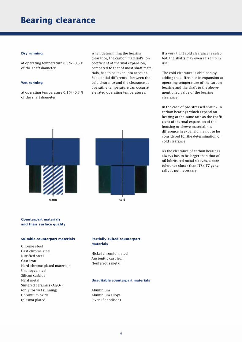
When determining the bearing
clearance, the carbon material's low
coefficient of thermal expansion,
compared to that of most shaft mate-
rials, has to be taken into account.
Substantial differences between the
cold clearance and the clearance at
operating temperature can occur at
elevated operating temperatures.
Partially suited counterpart
materials
Nickel chromium steel
Austenitic cast iron
Nonferrous metal
Unsuitable counterpart materials
Aluminium
Aluminium alloys
(even if anodised)
warm cold
6
The best running performance is
achieved with a surface roughness
of the counterpart material of
Rt ≤ 1 µm. A higher surface rough-
ness of Rt ≈ 2 µm will only result in
higher initial wear during the
running-in period.
Finely ground shafts, superfinished
for more onerous requirements, are
recommended for carbon bearings.
Drawn shafts are only allowable for
applications at low sliding speeds
and loads. Surface hardened and
drawn shafts are not suitable for
carbon bearings.
Not only the surface finish of the
counterpart surface is highly
important for the running behaviour
of the carbon bearing, but also the
counterpart material itself has a
certain impact.
The use of low-hardness, nickel con-
taining stainless steel as counterpart
material is not recommended, especi-
ally if other more suitable materials
can be used. Dry running, where
there is insufficient fluid lubrication,
or highly contaminated liquids may
lead to undesired scoring, resulting
in an increase in wear. Harder nickel-
free stainless steel types are pre-
ferred, at least for use at low or me-
dium load. Hardened chrome steel
(13 - 17 % Cr) has proved to be best,
also at higher loads.
The preference for hard counterpart
materials is mainly based on the fact
that the harder the counterpart mate-
rial, the easier the formation of the
graphite film on the counterpart
material.
[Clark, W. T. and Lancaster, J. K.
(1963). Wear 6. 467.]
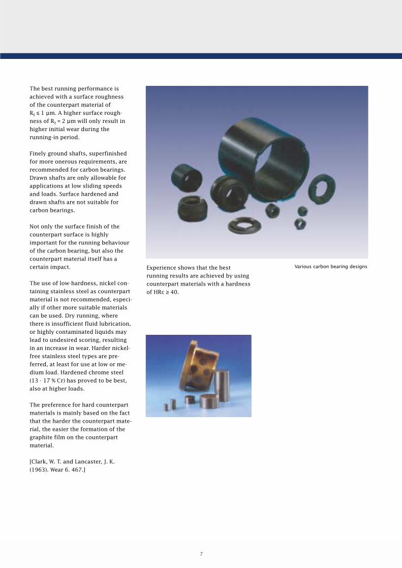
Experience shows that the best
running results are achieved by using
counterpart materials with a hardness
of HRc ≥ 40.
Various carbon bearing designs
7
Loading capacity
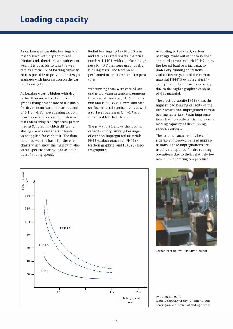
According to the chart, carbon
bearings made out of the very solid
and hard carbon material FH42 show
the lowest load bearing capacity
under dry running conditions.
Carbon bearings out of the carbon
material FH44Y3 exhibit a signifi-
cantly higher load bearing capacity
due to the higher graphite content
of this material.
The electrographite FE45Y3 has the
highest load bearing capacity of the
three tested non-impregnated carbon
bearing materials. Resin impregna-
tions lead to a substantial increase in
loading capacity of dry running
carbon bearings.
The loading capacity may be con-
siderably improved by lead impreg-
nations. These impregnations are
usually not applied for dry running
operations due to their relatively low
maximum operating temperature.
Radial bearings, Ø 12/18 x 10 mm
and stainless steel shafts, material
number 1.4104, with a surface rough-
ness Rt ≈ 0.7 µm, were used for dry
running tests. The tests were
performed in air at ambient tempera-
ture.
Wet running tests were carried out
under tap water at ambient tempera-
ture. Radial bearings, Ø 15/35 x 15
mm and Ø 20/35 x 20 mm, and steel
shafts, material number 1.4122, with
a surface roughness Rt ≈ (0.7 µm,
were used for these tests.
The p · v chart 1 shows the loading
capacity of dry running bearings
of our non-impregnated materials
FH42 (carbon graphite), FH44Y3
(carbon graphite) and FE45Y3 (elec-
trographite).
Carbon bearing test rigs (dry running)
8
As carbon and graphite bearings are
mainly used with dry and mixed
friction and, therefore, are subject to
wear, it is possible to take the wear
rate as a measure of loading capacity.
So it is possible to provide the design
engineer with information on the car-
bon bearing life.
As bearing wear is higher with dry
rather than mixed friction, p · v
graphs using a wear rate of 0.7 µm/h
for dry running carbon bearings and
of 0.1 µm/h for wet running carbon
bearings were established. Extensive
tests on bearing test rigs were perfor-
med at Schunk, in which different
sliding speeds and specific loads
were applied for each test. The data
obtained was the basis for the p · v
charts which show the maximum allo-
wable specific bearing load as a func-
tion of sliding speed,
p · v diagram no. 1:
loading capacity of dry running carbon
bearings as a function of sliding speed;
140
120
100
80
60
40
20
0,5 1,0 1,5 2,0
sliding speed
m/s
-FE45Y3-
-FH44Y3-
-FH42-
spec
ific
load
N/c
m2
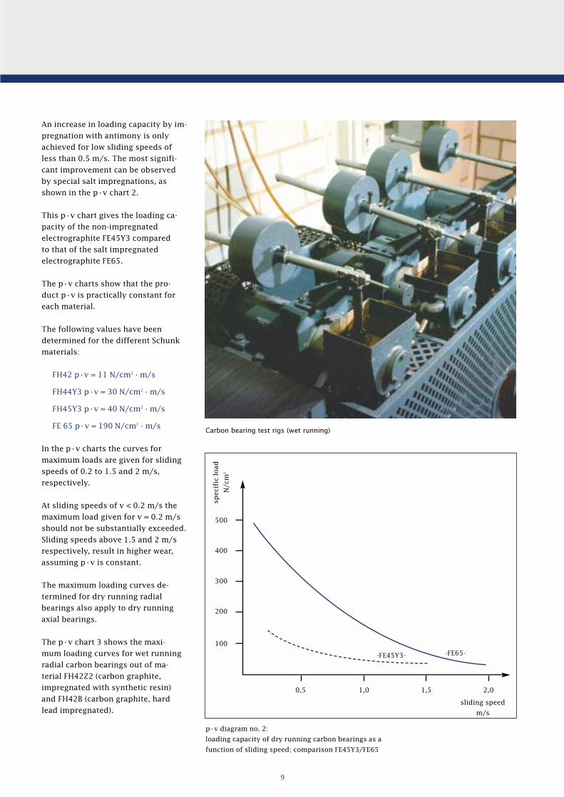
An increase in loading capacity by im-
pregnation with antimony is only
achieved for low sliding speeds of
less than 0.5 m/s. The most signifi-
cant improvement can be observed
by special salt impregnations, as
shown in the p · v chart 2.
This p · v chart gives the loading ca-
pacity of the non-impregnated
electrographite FE45Y3 compared
to that of the salt impregnated
electrographite FE65.
The p · v charts show that the pro-
duct p · v is practically constant for
each material.
The following values have been
determined for the different Schunk
materials:
FH42 p · v = 11 N/cm2 · m/s
FH44Y3 p · v = 30 N/cm2 · m/s
FH45Y3 p · v = 40 N/cm2 · m/s
FE 65 p · v = 190 N/cm2 · m/s
In the p · v charts the curves for
maximum loads are given for sliding
speeds of 0.2 to 1.5 and 2 m/s,
respectively.
At sliding speeds of v < 0.2 m/s the
maximum load given for v = 0.2 m/s
should not be substantially exceeded.
Sliding speeds above 1.5 and 2 m/s
respectively, result in higher wear,
assuming p · v is constant.
The maximum loading curves de-
termined for dry running radial
bearings also apply to dry running
axial bearings.
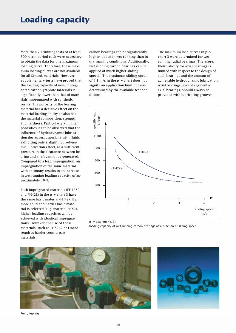
The p · v chart 3 shows the maxi-
mum loading curves for wet running
radial carbon bearings out of ma-
terial FH42Z2 (carbon graphite,
impregnated with synthetic resin)
and FH42B (carbon graphite, hard
lead impregnated).
Carbon bearing test rigs (wet running)
p ·v diagram no. 2:
loading capacity of dry running carbon bearings as a
function of sliding speed; comparison FE45Y3/FE65
9
500
400
300
200
100
spec
ific
load
N/c
m2
sliding speed
m/s
0,5 1,0
-FE45Y3- -FE65-
1,5 2,0
Loading capacity
More than 70 running tests of at least
500 h test period each were necessary
to obtain the data for one maximum
loading curve. Therefore, these maxi-
mum loading curves are not available
for all Schunk materials. However,
supplementary tests have proved that
the loading capacity of non-impreg-
nated carbon graphite materials is
significantly lower than that of mate-
rials impregnated with synthetic
resins. The porosity of the bearing
material has a decisive effect on the
material loading ability as also has
the material composition, strength
and hardness. Particularly at higher
porosities it can be observed that the
influence of hydrodynamic lubrica-
tion decreases, especially with fluids
exhibiting only a slight hydrodyna-
mic lubrication effect, as a sufficient
pressure in the clearance between be-
aring and shaft cannot be generated.
Compared to a lead impregnation, an
impregnation of the same material
with antimony results in an increase
in wet running loading capacity of ap-
proximately 10 %.
Both impregnated materials (FH42Z2
and FH42B) in the p · v chart 3 have
the same basic material (FH42). If a
more solid and harder basic mate-
rial is selected (e. g. material FH82),
higher loading capacities will be
achieved with identical impregna-
tions. However, the use of these
materials, such as FH82Z2 or FH82A
requires harder counterpart
materials.
The p · v chart 3 also shows that
The maximum load curves in p · v
chart 3 were determined for wet
running radial bearings. Therefore,
their validity for axial bearings is
limited with respect to the design of
such bearings and the amount of
achievable hydrodynamic lubrication.
Axial bearings, except segmented
axial bearings, should always be
provided with lubricating grooves.
carbon bearings can be significantly
higher loaded in wet running than in
dry running conditions. Additionally,
wet running carbon bearings can be
applied at much higher sliding
speeds. The maximum sliding speed
of 4.1 m/s in the p · v chart does not
signify an application limit but was
determined by the available test con-
ditions.
Pump test rig
p · v diagram no. 3:
loading capacity of wet running carbon bearings as a function of sliding speed
10
1000
800
600
400
200
spec
ific
load
N/c
m2
sliding speed
m/s
1 2 3 4
-FH42B-
-FH42Z2-
11
Fields of application
Fields of application and material
recommendations
The following summary of fields of
application for carbon bearings is not
complete. It comprises the currently
most important applications. We are
firmly convinced, however, that the
outstanding properties of carbon and
graphite materials will open further
fields of application for carbon
bearings.
We are constantly engaged, in close
cooperation with our customers, in
the improvement of our current mate-
rials and development of new grades
in order to meet new requirements.
Special applications may require the
selection of different carbon and gra-
phite materials. Please do not hesitate
to contact our Department of Appli-
cation Engineering as well as Re-
search and Development. Our staff
will be glad to help you!
The Schunk materials listed below
have been proven to be suitable for
the applications given and are to be
taken as recommendations.
Carbon bearings for veneer dryers
Split tube pump with carbon bearings
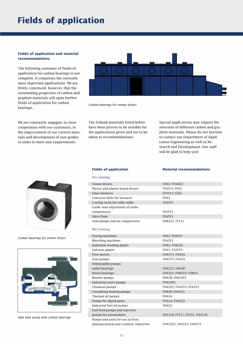
Fields of application
Dry running
Veneer dryers
Plaster and plaster board dryers
Glass furnaces
Conveyor belts for furnaces
Cooling racks for roller mills
Guide vane adjustment of turbo
compressors
Valve flaps
Vane pumps and air compressors
Wet running
Dyeing machines
Bleaching machines
Industrial washing plants
Galvanic plants
Flow meters
Gear pumps
Submergible pumps
radial bearings
thrust bearings
Booster pumps
Industrial water pumps
Chemical pumps
Circulating heating pumps
Thermal oil pumps
Pumps for liquid gases
Industrial fuel oil pumps
Fuel feed pumps and injection
pumps for automobiles
Pumps and units for use in food,
pharmaceutical and cosmetic industries
Material recommendations
FH42; FH44Z2
FE45Y3; FE65
FE45Y3; FE65
FH42
FE45Y3
FE45Y3
FE45Y3
FH42Z2; FF511
FH42; FE45Y3
FE45Y3
FH42; FH42Z2
FH42; FE45Y3
FH42Y3; FH42A
FH42Y3; FH42A
FH42Z2; FH42B
FH42Z5; FH82Z5; FH82A
FH42B; FH42ZP2
FH42ZP2
FH42Z2; FH42Y3; FE45Y3
FH42B; FH42Z2
FH42A
FH42A; FH42Z2
FH42A
FH531B; FF511; FF931; FH421B
FH42ZP2; FH42Z2; FH42Y3
Carbon bearings for veneer dryers

SchunkKohlenstofftechnik GmbH
Rodheimer Straße 5935452 Heuchelheim, Germany
Telefon: +49 (0) 641 608-0Telefax: +49 (0) 641 608-17 26
35.38 e/2003