Embed Size (px)
Citation preview
AM Syllabus (2021): Graphical Communication
1
AM SYLLABUS (2021)
GRAPHICAL COMMUNICATION AM 15
SYLLABUS
AM Syllabus (2021): Graphical Communication
2
Graphical Communication AM15 (Available in September)
Syllabus Paper I (3 hrs) + Paper II (3 hrs) + CAD coursework
Aims The aims of the syllabus are:
a) to further the ability to communicate information by graphical means;
b) to develop a competence in how to approach a graphical design exercise;
c) to foster the skill of representing graphically, using both freehand and accurate
drawings, plausible design concepts and solutions;
d) to develop an accurate level of draughtsmanship that respects established draughting
codes, practices and conventions.
e) to develop a knowledge of two-dimensional (2D) computer-aided draughting (CAD).
Assessment Objectives
Candidates will be required to:
a) demonstrate their ability to visualise and understand spatial relationships;
b) use the principles of plane and descriptive geometries to solve given problems;
c) apply successfully the methodical steps of analysis, synthesis and realisation to the
solution of graphical design exercises;
d) model orthographically and in three dimensions, graphical solutions utilising the
appropriate methods and techniques;
e) produce neat, clear and proportional drawings consistent with recognised codes and
conventions;
f) produce computer-generated drawings using computer-aided design software.
It is anticipated that this syllabus will form a two-year course with a time allocation of
around 360 hours. Candidates following this course are assumed to hold a pass grade of
the SEC29 Graphical Communication syllabus.
Scheme of Assessment
Graphical Communication shall have a continually assessed CAD component and a
written examination as detailed below.
The final grade (grade A to grade E) shall be based on the combined marks obtained in
the written examination and the CAD portfolio. To qualify for a pass in the subject,
candidates must satisfy the examiners in both parts.
AM Syllabus (2021): Graphical Communication
3
Marks distribution
Written examination: 80% of total marks
CAD portfolio: 20% of total marks
i) The written examination
The examination will consist of two written papers, Paper I and Paper II, of three
hours duration each. Paper I and Paper II carry equal weightings of marks. The
candidates must satisfy the examiners in both papers.
Any examination question can test material from more than one topic.
Candidates are required to provide their own A2 size drawing board and
draughting equipment. In particular the candidates should have a superbow
compass capable of handling measurements of around 160mm. Such a compass
should also be expandable, by the fitment of a matching extension.
Only non-programmable calculators are allowed. The use of draughting aids is
permitted.
Questions in both papers will be set in SI units and in accordance with the revised
editions of PP8888-1 and PP8888-2.
ii) The CAD portfolio
Each candidate shall present a portfolio of three hard-copy, graded CAD practical
exercises, set by the teacher to cover the syllabus. It is suggested that the first two
exercises will be held during the first year of the course, with the third exercise
left for the second year. These exercises shall be marked by the class tutor during
the two-year course, according to a marking scheme, guide- lines and
instructions. The mark of the portfolio shall be submitted to the MATSEC Board
by a date stipulated by the unit.
Private candidates
Private candidates are to have a tutor who is knowledgeable in the subject and is
familiar with the requirements of the syllabus to guide them in the process. Private
candidates and their tutor are to fill in an authentication form which can be
obtained from the MATSEC website. Private Candidates are to submit all
exercises to the MATSEC Support Unit, for assessment by the Markers Panel, by
the date stipulated by the unit. Candidates may be called for an interview about
their work.
AM Syllabus (2021): Graphical Communication
4
The Subject Content
The written examination
Paper I (max 100 marks)
Paper I is common to both Engineering Drawing (AM09) and Graphical Communication
(AM15). It will contain six questions of which the candidates are required to answer any
five. All questions will carry equal marks. All five questions are to be answered on A2
size sheets, which will be provided.
1. The cone and the conic sections.
Conics regarded as sections of a right cone.
Conics regarded as plane loci of a moving point using the ratio of eccentricity.
The construction of a tangent and a normal at a point on the conics.
The construction of a tangent and a normal to the ellipse and parabola from a given point
outside the curve.
Use of the focal sphere to find the ratio of eccentricity, the position of the directrix and
the focal point/s of a conic.
Drawing the conics using the following methods:
o the parabola in a rectangle; o the ellipse using the auxiliary circles; o the ellipse in a rectangle; o the ellipse using the intersecting arc method, PF1+ PF2 = V1V2; o the hyperbola given the asymptotes and a point on it; o the hyperbola using the intersecting arc method, PF1 - PF2 = V1V2.
The hyperbola and the auxiliary circle. Knowing the directrices, finding the asymptotes and vice versa.
The centre of curvature at a point on the ellipse, parabola and hyperbola, the point not
being a vertex.
2. Cycloidal curves
The construction of the cycloid, epicycloid, hypocycloid and their derived curves.
The tangent, normal and centre of curvature at a point on the cycloid and its trochoids.
3. Spiral curves
The Archimedean spiral: the drawing of one or more convolutions extending between
two given radii; the tangent and normal at a point on it.
AM Syllabus (2021): Graphical Communication
5
4. Helices and screw threads
The helix: right-hand and left-hand.
The true length of the helix.
The helix angle, excluding its application as being the true angle of the tangent drawn at
any point on the helix.
Applications of the helix: the helical vane; round-, square- and rectangular-section
springs; one- and two-start, internal or external, vee and square threads.
5. Involute Spur Gears
The involute of a circle.
The analysis and drawing of gears in mesh. The number of teeth to be drawn in mesh
shall be limited to five.
The construction of a gear tooth profile of an involute spur gear. Drawing the tooth side
using both the true involute method and approximate reproductive methods.
The rack and pinion.
6. Coplanar loci of points on moving mechanisms.
Slider-crank mechanism.
Equal and unequal connected cranks.
Watt’s straight-line motion.
Quick-return mechanism.
Geared link mechanisms.
The drawing of displacement diagrams related to the above.
7. Cams
Types of motion: Dwell, Uniform Velocity (UV), Simple Harmonic Motion (SHM),
Uniform Acceleration (UA), Uniform Retardation (UR), and Uniform Acceleration and
Retardation (UAR).
Types of followers: knife-edged, flat-foot and roller-ended.
The line of action of the follower may be in-line or offset relative to the axis of the cam.
Types of cams: wedge, disc, cams with radial arm followers and end cams.
Problems will only be set to derive the cam profile from given cam and follower data.
8. Projections
Isometric projection and the use of the isometric scale.
First and second auxiliary projection of shapes and solids.
9. Projection of Lines
Lines inclined to the horizontal plane (H.P.) and the vertical plane (V.P.); the
determination of their true lengths, their true inclination to the H.P. and the V.P.
AM Syllabus (2021): Graphical Communication
6
Skew lines; the shortest distance between two skew lines; the bearing and slope of the
shortest distance.
10. Planes
Planes inclined to the horizontal plane (H.P.) and the vertical plane (V.P.); true angles
between two planes: the dihedral angle.
The lines of intersection between two triangles or other plane laminae.
Oblique planes and their traces; the conversion of an oblique plane into a perpendicular
inclined plane by means of auxiliary views; the true inclination to the horizontal and
vertical planes determined using auxiliary projection or the technique of rabatment.
Lines, geometrical shapes and solids resting on, or cut by oblique planes.
11. Intersection of Solids
Intersections of geometrical solids, between:
a) two prisms;
b) two cylinders;
c) prism and cylinder;
d) cone and prism/cylinder;
e) pyramid and prism/cylinder;
f) sphere/hemisphere and prism/cylinder;
g) sphere and cone.
All solids are right, with the cones and pyramids standing on their bases.
Prisms and cylinders may be inclined to one plane of reference.
All above categories may include cases of offset middle planes.
The construction of the curve of intersection that results on:
a) palm-ended rods and eccentric cylinders;
b) rods of hexagonal section joined to cones or spheres.
12. Solids in contact
Spheres in mutual contact with each other.
Spheres in contact with cones standing on their base.
The projection of the points of contact.
13. Developments
The development of surfaces of right and oblique truncated prisms, cylinders, cones and
pyramids.
Development by triangulation of transition pieces; the end connections may have
different cross-sections, not necessarily parallel to each other.
AM Syllabus (2021): Graphical Communication
7
14. Graphical Statics
Coplanar concurrent and non-concurrent forces.
The use of Bow’s notation, the polar diagram and the link polygon to determine
graphically the resultant/equilibrant of a system of forces.
Shear Force and Bending Moment diagrams for:
a) light cantilevers;
b) light simply supported beams;
c) light hinged beams - the beam is made of two parts, hinged together,
when these are subjected to vertical point loads and uniformly distributed loads (udl).
Framed structures; the use of space and force diagrams to framework problems to
determine graphically the reactions and forces in members; the distinction between struts
and ties. The applied external loading is limited to vertical point loads.
Paper II (max 100 marks)
Paper II will consist of four questions with the candidates being required to answer them
all. Candidates will answer the questions on the A2 drawing sheets provided.
Knowledge of the topics covered in Paper I is assumed. Paper II will be based on
graphical communication applications found in such areas as the following:
1. The general environment
Graphical presentations of: logograms; ideograms and trade symbols; Advertising and
display of products and themes via poster and leaflet design.
2. Graphical analysis, comparison and presentation of data
An understanding of the values of line graphs, block graphs, bar charts, pie charts, flow
charts and layout charts for the rapid and effective communication of information,
comparative information and statistics.
3. Perspective Drawing
Estimated one- and two-point perspective drawing applied to simple architectural plans
of the local habitat. Freehand perspective drawing.
The candidates are expected to produce proper perspective drawings from given
orthographic views. The candidates should also be able to suggest suitable materials for
the components featured in such an exercise.
AM Syllabus (2021): Graphical Communication
8
4. Other methods of graphical illustration
Planometric drawing and isometric drawing, applied to simple architectural plans of the
local habitat. Freehand drawing using these methods.
The candidates are expected to produce proper planometric/isometric drawings from
given orthographic views.
5. Graphical Techniques
The enhancement of drawings by:
a) Selecting between portrait or landscape formats to make the best possible use of
the drawing sheet area.
b) Using colour effectively: the colour wheel; cool and warm colours and their effect
on enclosed space; the psychology of colour.
c) Emphasising parts of a drawing’s outline.
d) Representing the effect of light falling on objects (tone). Only a basic knowledge
is expected.
e) Representing the texture of key materials like wood, metal, glass and polymers.
Only a basic knowledge is expected.
f) Exploring the use of different drawing media: pencil, ink (fine-liner) and felt-tip
in relation to (d) and (e) above.
6. The Design Process
The graphic design process as broken down in the following steps:
a) The Situation
b) The Design Brief
c) Written Analysis
d) Graphical Analysis
e) Design Synthesis
f) Final Realisation
Candidates are expected to appreciate the role of freehand drawing and graphical
communication in general, while executing steps (d), (e) and (f) of the design process.
AM Syllabus (2021): Graphical Communication
9
The Computer-Aided Draughting (CAD) portfolio
1.
a)
General Guidelines
CAD is an obligatory component of the subject. It carries 20% of the global mark.
b) The CAD component is continually assessed by the class tutor responsible for the
subject.
c) Computer draughting assignments based on AutoCAD®
up to 2D level will be
covered during the 2 years duration of the course.
d) A portfolio shall be compiled by each candidate, and will contain hard copies (A3
size) of the assignments set by the class tutor and their computer generated
solutions done by the candidate.
e) The candidates’ portfolio with solutions marked by the tutor will be kept under
strict confidential cover.
f) The three CAD assignments set by the class tutor shall be graded examples
that progress with the knowledge gained both in the application of computer
software and subject matter.
2. Aims and Objectives
The course is aimed at providing course participants with the fundamentals of Computer- Aided Draughting (CAD) using AutoCAD
® software packages to draw 2D plans and/or
2D projections. This course requires the candidate to:
a) demonstrate competency in using some of the standard available features of a
CAD application;
b) to create and manipulate objects or elements and to modify objects or elements;
c) be able to change object properties;
d) be able to present a drawing in the orthographic and isometric systems of
drawing;
e) undertake printing or plotting activity in colour/monochrome with specific scales.
AM Syllabus (2021): Graphical Communication
10
3. CAD Content
Assignment 1 places emphasis on correct coordinate input, precise length and orientation of entities, efficient methods and practices.
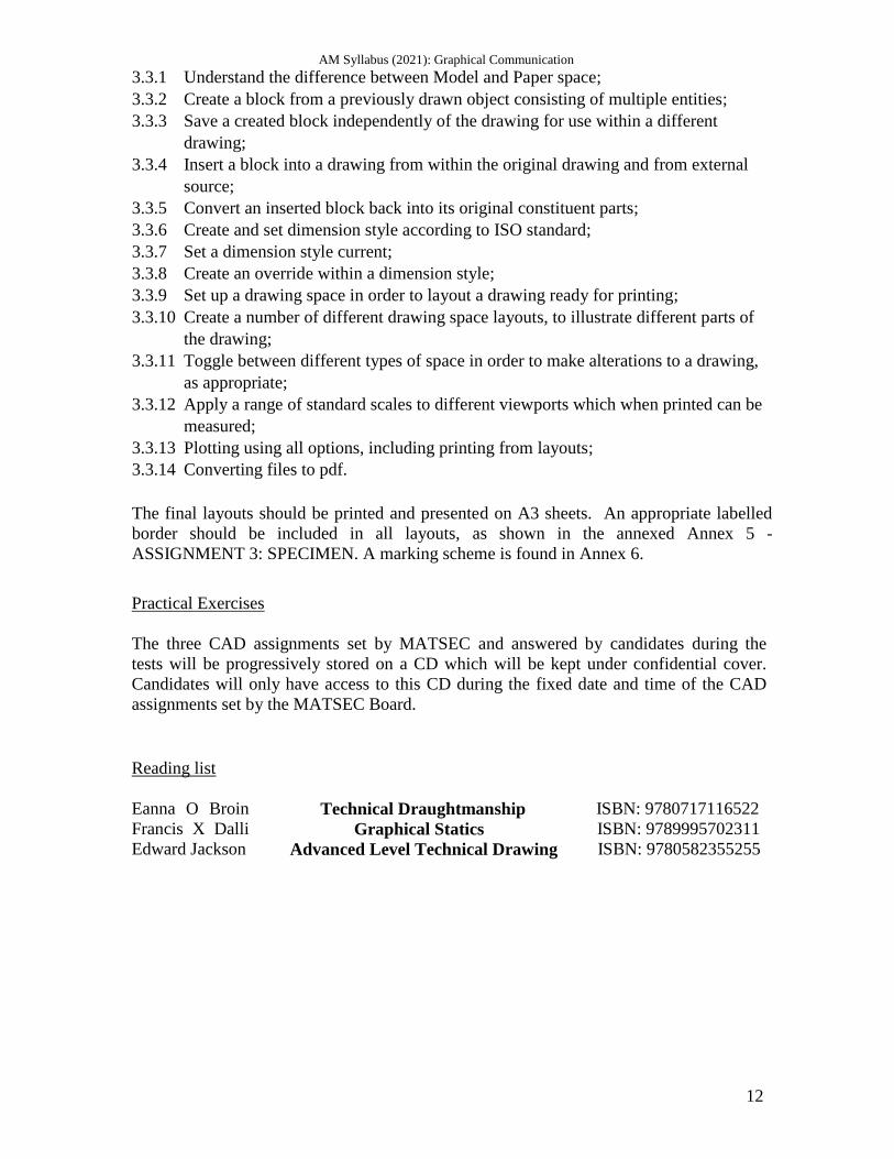
Assignment 1 carries a total of 5 marks. It will comprise of the vector design of THREE RECOGNISED LOGOS, either
individually chosen by candidate or set by lecturer as three class tasks.
Said logos will display basic knowhow to application of the following topics and
AutoCAD® commands:
3.1.1 Open and close AutoCAD®
application. Only one drawing will be required to
be open at any given time;
3.1.2 Create a new drawing. Candidate should be able to start a new drawing using the
standard metric template acadiso.dwt;
3.1.3 Set model environment i.e. units, limits etc;
3.1.4 Set interface settings e.g. snap, grid, ortho;
3.1.5 Use zooming tools;
3.1.6 Panning a drawing;
3.1.7 Understand & use Absolute and Relative Cartesian coordinate systems;
3.1.8 Drawing commands as Line, Circle, Arc;
3.1.9 Draw rectangle, polygon, ellipse;
3.1.10 Hatch a closed entity to represent sections;
3.1.11 Use snapping tools for accuracy;
3.1.12 Erase & oops;
3.1.13 Copy and Move objects;
3.1.14 Apply Chamfers and Fillets;
3.1.15 Trim operation;
3.1.16 Create and set text styles, using only default options;
3.1.17 Select plotter/ printer;
3.1.18 Plot all, part of drawing to a given scale from model space;
3.1.19 The Pline and Spline drawing commands;
3.1.20 The Rotate, Scale, Stretch, Extend & Offset modifying commands including
precommand editing;
3.1.21 Mirror and array.
3.1.22 Add a new title block;
The logo designs should collectively show clear mastery of the basic commands
mentioned. Marks will be allotted for research, proper adaptation, composition and
presentation of work.
The final assignment should be printed and presented on a one-sided A3 sheet, bordered
and labeled accordingly, as shown in Annex 1 - ASSIGNMENT 1: SPECIMEN. A
marking scheme is found in Annex 2.
AM Syllabus (2021): Graphical Communication
11
Assignment 2 places emphasis on the options available for the various drawing and
editing commands that result in increased speed without loss of accuracy. The more
advanced features of tracking, dynamic input, etc. are covered.
Assignment 2 carries a total of 5 marks.
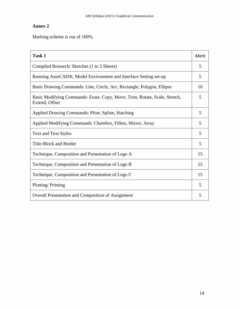
It will comprise of the conventional to digital designs of one, small, handheld item, be it a domestic appliance, electronic component or tool. The exercise will cover the topics and AutoCAD
® commands listed below. Assignment 2
also assumes the content listed for Assignment 1.
3.2.1 Open multiple drawings and switch between them;
3.2.2 Create and save an AutoCAD drawing template;
3.2.3 Create named views & recall them;
3.2.4 Edit polylines and spline: decurve, fit, thickness, join and explode;
3.2.5 Break and Explode operations;
3.2.6 Create layers and assign properties such as line weights, line types, colour;
3.2.7 Set a layer current;
3.2.8 Modify status: On, Off, Freeze, Thaw, Lock, Unlock;
3.2.9 Modify layer attributes;
3.2.10 Create and set text styles with different fonts using all options;
3.2.11 Understand the difference between mtext and text commands;
3.2.12 Set a text style current;
3.2.13 Understand the text alignment abbreviations e.g. TR, TC, TL etc.;
3.2.14 Plot all, part of drawing from model space using all options.
The study of the item should consist of:
pictorial sketches;
technical drawings in Orthographic Projection, including main dimensions;
a bordered, Orthographic layout with the use of AutoCAD®
The final assignment should be printed and presented on a one-sided A3 sheet, bordered
and labeled accordingly, as shown in the annexed Annex 2 - ASSIGNMENT 2:
SPECIMEN. A marking scheme is found in Annex 4.
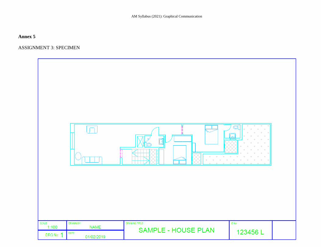
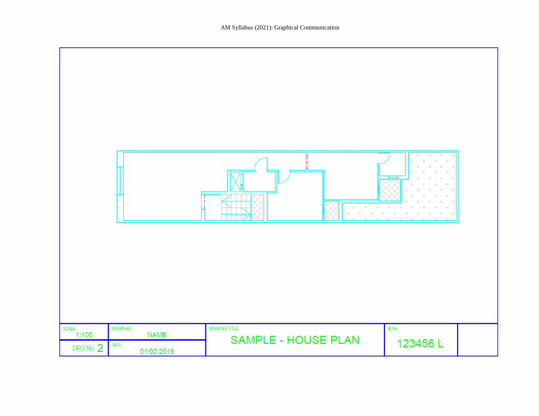
Assignment 3 places emphasis on manipulation of different layouts that include viewports
with different scales, dimensions and other annotations.
Assignment 3 carries a total of 10 marks.
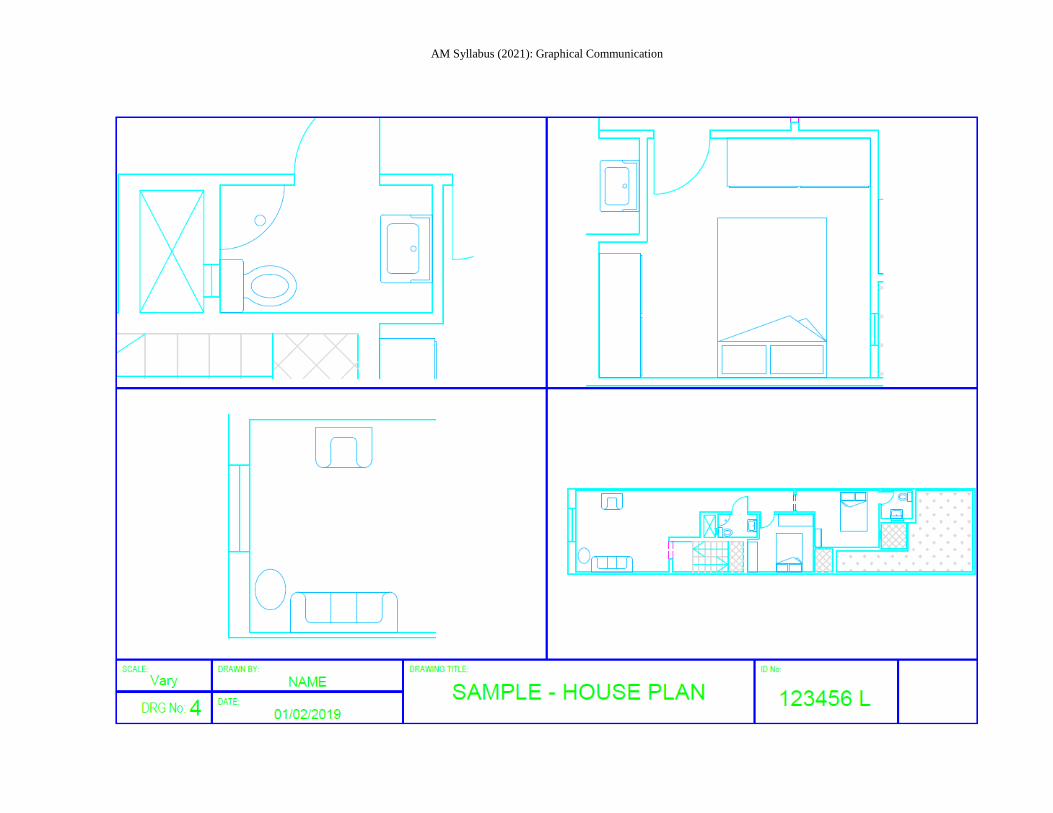
Architectural plans of an apartment, floor or other living space will be the culminating
focus of this final module, as guided by the learning criteria enlisted below.
Assignment 3 assumes knowledge of both assignment 1 and 2. The exercise will cover the
topics listed below.
AM Syllabus (2021): Graphical Communication
12
3.3.1 Understand the difference between Model and Paper space;
3.3.2 Create a block from a previously drawn object consisting of multiple entities;
3.3.3 Save a created block independently of the drawing for use within a different
drawing;
3.3.4 Insert a block into a drawing from within the original drawing and from external
source;
3.3.5 Convert an inserted block back into its original constituent parts;
3.3.6 Create and set dimension style according to ISO standard;
3.3.7 Set a dimension style current;
3.3.8 Create an override within a dimension style;
3.3.9 Set up a drawing space in order to layout a drawing ready for printing;
3.3.10 Create a number of different drawing space layouts, to illustrate different parts of
the drawing;
3.3.11 Toggle between different types of space in order to make alterations to a drawing,
as appropriate;
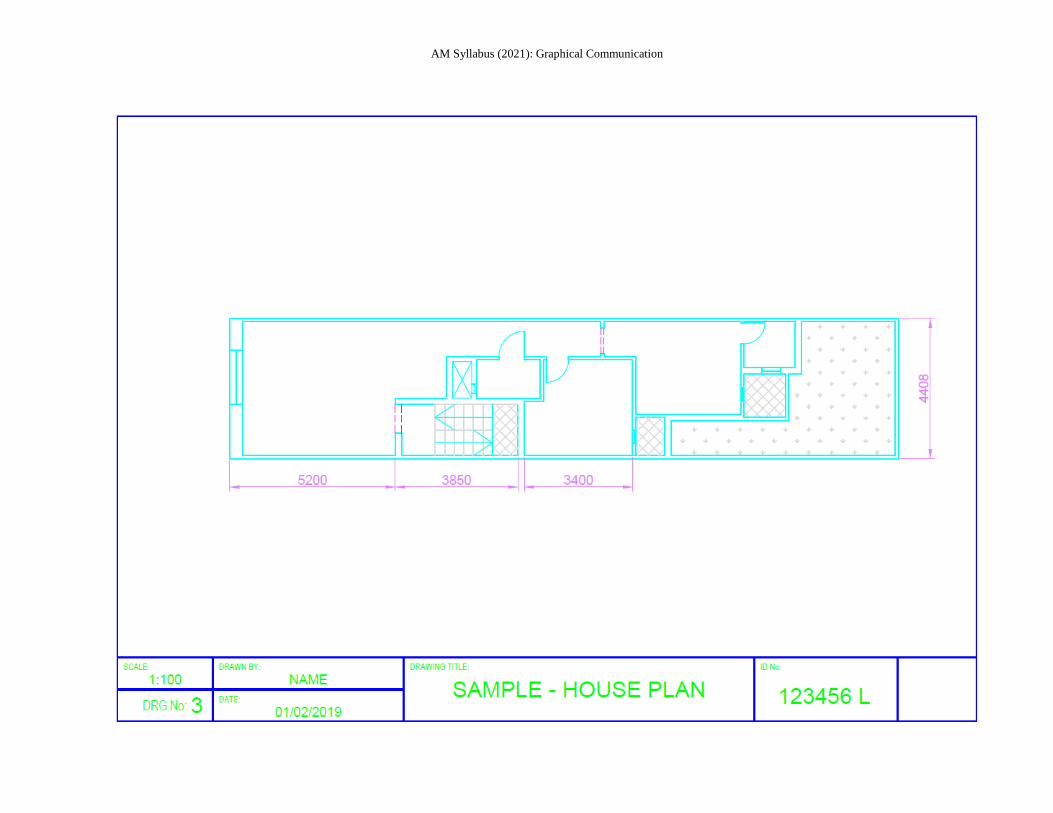
3.3.12 Apply a range of standard scales to different viewports which when printed can be
measured;
3.3.13 Plotting using all options, including printing from layouts;
3.3.14 Converting files to pdf.
The final layouts should be printed and presented on A3 sheets. An appropriate labelled
border should be included in all layouts, as shown in the annexed Annex 5 -
ASSIGNMENT 3: SPECIMEN. A marking scheme is found in Annex 6.
Practical Exercises
The three CAD assignments set by MATSEC and answered by candidates during the
tests will be progressively stored on a CD which will be kept under confidential cover.
Candidates will only have access to this CD during the fixed date and time of the CAD
assignments set by the MATSEC Board.
Reading list
Eanna O Broin
Francis X Dalli
Edward Jackson
Technical Draughtmanship
Graphical Statics
Advanced Level Technical Drawing
ISBN: 9780717116522
ISBN: 9789995702311
ISBN: 9780582355255
AM Syllabus (2021): Graphical Communication
Annex 1
ASSIGNMENT 1: SPECIMEN
AM Syllabus (2021): Graphical Communication
14
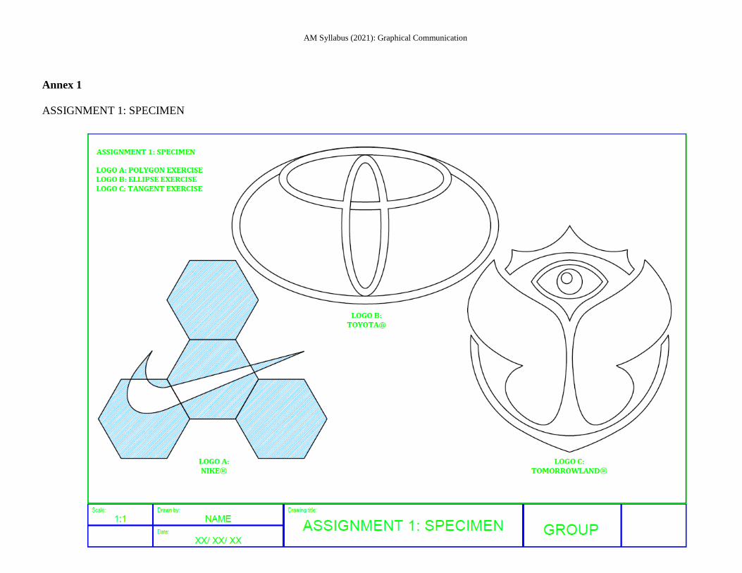
Annex 2
Marking scheme is out of 100%.
Task 1 Mark
Compiled Research/ Sketches (1 to 3 Sheets) 5
Running AutoCAD®, Model Environment and Interface Setting set-up 5
Basic Drawing Commands: Line, Circle, Arc, Rectangle, Polygon, Ellipse 10
Basic Modifying Commands: Erase, Copy, Move, Trim, Rotate, Scale, Stretch,
Extend, Offset
5
Applied Drawing Commands: Pline, Spline, Hatching 5
Applied Modifying Commands: Chamfers, Fillets, Mirror, Array 5
Text and Text Styles 5
Title-Block and Border 5
Technique, Composition and Presentation of Logo A 15
Technique, Composition and Presentation of Logo B 15
Technique, Composition and Presentation of Logo C 15
Plotting/ Printing 5
Overall Presentation and Composition of Assignment 5
AM Syllabus (2021): Graphical Communication
Annex 3
ASSIGNMENT 2: SPECIMEN
AM Syllabus (2021): Graphical Communication
16
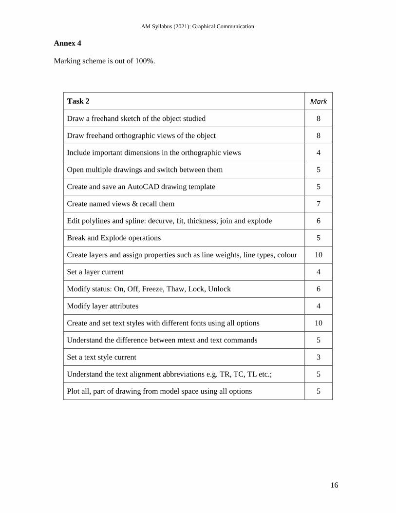
Annex 4
Marking scheme is out of 100%.
Task 2 Mark
Draw a freehand sketch of the object studied 8
Draw freehand orthographic views of the object 8
Include important dimensions in the orthographic views 4
Open multiple drawings and switch between them 5
Create and save an AutoCAD drawing template 5
Create named views & recall them 7
Edit polylines and spline: decurve, fit, thickness, join and explode 6
Break and Explode operations 5
Create layers and assign properties such as line weights, line types, colour 10
Set a layer current 4
Modify status: On, Off, Freeze, Thaw, Lock, Unlock 6
Modify layer attributes 4
Create and set text styles with different fonts using all options 10
Understand the difference between mtext and text commands 5
Set a text style current 3
Understand the text alignment abbreviations e.g. TR, TC, TL etc.; 5
Plot all, part of drawing from model space using all options 5
AM Syllabus (2021): Graphical Communication
Annex 5
ASSIGNMENT 3: SPECIMEN
AM Syllabus (2021): Graphical Communication
AM Syllabus (2021): Graphical Communication
AM Syllabus (2021): Graphical Communication
AM Syllabus (2021): Graphical Communication
21
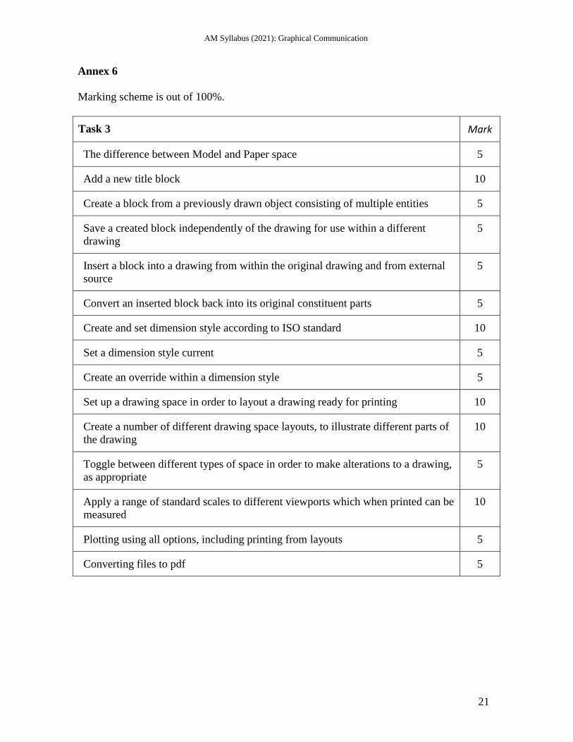
Annex 6
Marking scheme is out of 100%.
Task 3 Mark
The difference between Model and Paper space 5
Add a new title block 10
Create a block from a previously drawn object consisting of multiple entities 5
Save a created block independently of the drawing for use within a different
drawing
5
Insert a block into a drawing from within the original drawing and from external
source
5
Convert an inserted block back into its original constituent parts 5
Create and set dimension style according to ISO standard 10
Set a dimension style current 5
Create an override within a dimension style 5
Set up a drawing space in order to layout a drawing ready for printing 10
Create a number of different drawing space layouts, to illustrate different parts of
the drawing
10
Toggle between different types of space in order to make alterations to a drawing,
as appropriate
5
Apply a range of standard scales to different viewports which when printed can be
measured
10
Plotting using all options, including printing from layouts 5
Converting files to pdf 5


![Communication Skills [CMS]Definition of equilibrant, relation between resultant and equilibrant, equilibrant of concurrent and nonconcurrent force system. Analytical and graphical](https://img.pdfslide.us/doc/110x75/5eb5b15d844c3f6e542f1364/communication-skills-cms-definition-of-equilibrant-relation-between-resultant.jpg)