Embed Size (px)
Citation preview

1
Graphene Quantum Dots as a Green Photosensitizer with
Carbon Doped ZnO Nanorods for Quantum Dot Sensitized
Solar Cell Applications
Tanmoy Majumder and Suvra Prakash Mondal*
Department of Physics, National Institute of Technology, Agartala, India -799046.
*Corresponding Author’s email: [email protected]
Abstract
Graphene quantum dots (GQDs), N doped graphene quantum dots (NGQDs) and S, N co-doped
graphene quantum dots (SNGQDs) were synthesized using hydrothermal methods. All GQDs
were attached with carbon doped ZnO nanorods (C-ZnO NRs) grown on fluorine doped tin oxide
(FTO) coated glass substrates, for the fabrication of metal free eco-friendly quantum dot
sensitized solar cells (QDSSCs). SNGQDs decorated nanorods based solar cells demonstrated
maximum open circuit voltage (VOC ~36 mV), short circuit current (JSC~1.84 mA/cm2) and
power conversion efficiency (η~0.293 %) compared to other devices.
Keywords: GQDs, C- ZnO NR and QDSSC
Manuscript Click here to access/download;Manuscript;Manuscript_S PMondal.docx
Click here to view linked References 1 2 3 4 5 6 7 8 9 10 11 12 13 14 15 16 17 18 19 20 21 22 23 24 25 26 27 28 29 30 31 32 33 34 35 36 37 38 39 40 41 42 43 44 45 46 47 48 49 50 51 52 53 54 55 56 57 58 59 60 61 62 63 64 65
2
1. Introduction
Innovative ideas are required to harvest incident solar energy into electrical energy with better
efficiency to meet our clean energy demand. The conventional silicon and inorganic thin film
solar cells demonstrated power conversion efficiency varying from 10-30% [1]. However, such
solar cells are quite expensive due to the source materials, high vacuum and elevated temperature
fabrication including several lithographic steps. Due to these limitations, intensive research
works have been carried out on third generation solar cells such as dye sensitized solar cells
(DSSCs), organic solar cells and quantum dot sensitized solar cells (QDSSCs). These new type
of solar cells can achieve highest theoretical photoconversion efficiency up to 44.7%, with
minimal fabrication cost and easy synthesis procedure [2,3]. Several research works have been
carried out by sensitizing TiO2 or ZnO nanostructures with low band gap semiconductor QDs
such as CdS, CdSe, PbS, PbSe, CdTe etc[4-6] . To best of our knowledge, the maximum device
performance was obtained with CdSeTe decorated CdS QD sensitized TiO2 nanoparticles films
of power conversion efficiency (η) ~ 9.48% [7]. Although, these chalcogenide semiconductors
offers excellent size tunable optical band gap, high photoabsorption and favorable band
alignment, but most of these QDs are health hazardous due to the presence of highly toxic Cd or
Pb based elements. On the other hand, environmental friendly, nontoxic QDs such as CuInS2,
CuInSe2 and CuInSeS have been utilizing as photosensitizer in QDSSC. The highest reported
photoconversion efficiency with such QDs was found to be 11.66% [8].
Recently, graphene quantum dots (GQDs), have been paid much attention for their size tunable
optical absorption and emission similar to semiconductor QDs. Such carbon based zero
dimensional (0D) nanomaterials are nontoxic, eco-friendly, chemically inert and can be easily
synthesized at minimum cost [9]. Doping is a common method to enhance the photoabsorption
and photoinduced charge transport from GQDs to semiconductors. Several kinds of doping
1 2 3 4 5 6 7 8 9 10 11 12 13 14 15 16 17 18 19 20 21 22 23 24 25 26 27 28 29 30 31 32 33 34 35 36 37 38 39 40 41 42 43 44 45 46 47 48 49 50 51 52 53 54 55 56 57 58 59 60 61 62 63 64 65

3
elements such as S, N, B, P, F etc. were investigated to modulate optical and electrical properties
of the GQDs [10-12]. Instead of using conventional semiconductor QDs, graphene quantum dot
sensitized solar cells will be attractive for low cost, environmental friendly solar energy
conversion.
In this letter, we have fabricated carbon doped ZnO nanorods (C-ZnO NRs) photoanode based
solar cell. Graphene quantum dots (GQDs), nitrogen doped graphene quantum dots (NGQDs)
and sulfur, nitrogen co-doped graphene quantum dots (S,NGQDs) were utilized as
photosensitizer for quantum dot sensitized solar cell applications.
2. Experimental
All graphene quantum dots (GQDs) were synthesized by hydrothermal process [13-15]. ZnO
NRs were grown on FTO coated glass substrates by a two step chemical process. The detail
experimental procedures and growth mechanism were reported elsewhere [14]. C doping was
carried out by dipping the ZnO NRs in 0.1 M glucose solutions followed by heating at 120oC.
Finally, all samples were annealed at 300oC for 3 hours. For the attachment of QDs, nanorods
were dipped in GQDs, NGQDs and SNGQDs solutions for 2 hours. The samples were
thoroughly rinsed with DI water after attachment and annealed at 120oC for 3 hours in air
atmosphere. The surface topography and elemental analysis of carbon doped ZnO nanorods and
ZnO nanorods were studied using a NOVA NANO (FEI, USA) scanning electron microscope
(SEM). Transmission electron microscopy (TEM) measurements were carried out using a JEOL
JEM-2100F microscope.To study the chemical bonding of GQDs and C-ZnO NRs, X-ray
photoelectron spectroscopy (XPS) study were performed using PHI 5000 Versa Probe II
(ULVAC-PHI, INC, Japan) instrument. UV-Vis absorption spectra of the graphene quantum dots
were recorded using a PerkinElmer Lambda 950 spectrometer. To fabricate quantum dot
1 2 3 4 5 6 7 8 9 10 11 12 13 14 15 16 17 18 19 20 21 22 23 24 25 26 27 28 29 30 31 32 33 34 35 36 37 38 39 40 41 42 43 44 45 46 47 48 49 50 51 52 53 54 55 56 57 58 59 60 61 62 63 64 65

4
sensitized solar cells (QDSSCs), GQDs sensitized NRs were used as working electrodes and
platinum coated FTO substrates were used as counter electrodes. The iodine based electrolyte
solution (Iodolyte Z-50, Solaronix) was introduced in between the two electrodes. The current-
voltage (J-V) characteristics of the QDSSCs were measured using a source meter (B2912A,
Agilent, USA) under illumination of 100 mW/cm2 light (AM 1.5) from a solar simulator
(Enlitech, Tiwan).
3. Results and Discussions
Fig. 1 (a) (b) and (c) represent the plane view TEM micrographs of GQDs, NGQDs and
SNGQDs. The average size of GQDs, NGQDs and SNGQDs estimated from the micrographs are
5.2 nm, 4.5 nm and 4 nm, respectively. The corresponding high resolution TEM images of all
GQDs are presented at the inset of Fig. 1(a), (b) and (c), respectively. Interestingly, all GQDs are
highly crystalline with interplaner spacing of ~0.34 nm, which is similar to the (002) facet of
graphitic carbon [14]. The full range XPS spectra of GQDs, NGQDs and SNGQDs are shown in
Fig. 1(d), (e) and (f), respectively. The major binding energy peaks at 283.2 eV and 531.2 eV,
are attributed to the presence of C 1s and O 1s electrons, which are the key elements of GQDs.
In addition to C1s and O1s peaks, an extra peak at 399.2 eV has been observed in NGQDs,
which is ascribed to N1s electrons. Similarly, XPS spectrum of SNGQDs shows two more peaks
at 167.3 eV and 399.4 eV, which are denoted to S 2p and N 1s electrons. Our XPS study
confirmed the doping of N atoms in NGQDs and S, N atoms in SNGQDs.
Fig. 2(a) and (b) shows the UV-Vis absorption spectra of GQDs, NGQDs and SNGQDs. The
absorption spectra of all graphene quantum dots shows two major peaks at wavelength 215 nm
and 338 nm for GQDs, 238 nm and 334 nm for NGQDs and 222 nm and 333 nm for SNGQDs,
respectively. The origin of such UV absorption at 215-222 nm is attributed to π→π* transition of
1 2 3 4 5 6 7 8 9 10 11 12 13 14 15 16 17 18 19 20 21 22 23 24 25 26 27 28 29 30 31 32 33 34 35 36 37 38 39 40 41 42 43 44 45 46 47 48 49 50 51 52 53 54 55 56 57 58 59 60 61 62 63 64 65

5
C=C bonds and at 338-333 nm corresponds to n→π* transition of C=O bonds in GQDs,
respectively [13-15].
Fig. 3(a) and (b) represents the top view SEM micrographs of ZnO NRs before and after C
doping. The nanorods were grown uniformly on FTO substrates and no significant
microstructural modification have been observed after doping The average diameter and density
of nanorods estimated from the micrographs are found to be ~130 nm and ~1.85×10⁹ /cm2,
respectively. The chemical mapping confirmed the presence of the key elements zinc and oxygen
in ZnO and C-ZnO nanorods (inset of Fig 3(a) and (b)). The presence of significant amount of
carbon in C-ZnO NRs (inset of Fig.3 b) confirmed the doping. However, existence of small
amount of carbon content in pristine ZnO is due to contamination during sample treatment. Fig.
3(c) and (d) represent full range XPS spectra of ZnO and C-ZnO NRs. Both spectra describe the
presence of zinc and oxygen peaks which arises from ZnO nanorods. However, we have also
observed a detectable peak at ~284.4 eV, which is attributed to the presence of C 1s electrons in
both nanorods. In our study, the C peak may arise either from surface contamination or impurity
doping. To verify the origin of C peak, high resolution XPS (HRXPS) spectra of C1s electrons
were recorded after surface cleaning of the nanorods (using Ar ions). Interestingly, after
cleaning, the C peak at ~284.4 eV for pristine ZnO NRs has been disappeared (inset of Fig. 3(c)).
But, the C 1s peak in C-ZnO NRs is remained unchanged and confirmed the successful insertion
of carbon atoms in ZnO lattice (inset of Fig. 3(d)).
To explore the potential use of GQDs as photosensitizer, solar cells were fabricated after
attachment of GQDs, NGQDs and SNGQDs with C-ZnO NRs separately. Fig. 4(a) depicts the
schematic representation of QDSSC device structure. The current-voltage (J-V) characteristics of
GQDs, NGQDs and SNGQDs decorated C-ZnO NRs photoanodes are presented in Fig. 4(b).
1 2 3 4 5 6 7 8 9 10 11 12 13 14 15 16 17 18 19 20 21 22 23 24 25 26 27 28 29 30 31 32 33 34 35 36 37 38 39 40 41 42 43 44 45 46 47 48 49 50 51 52 53 54 55 56 57 58 59 60 61 62 63 64 65
6
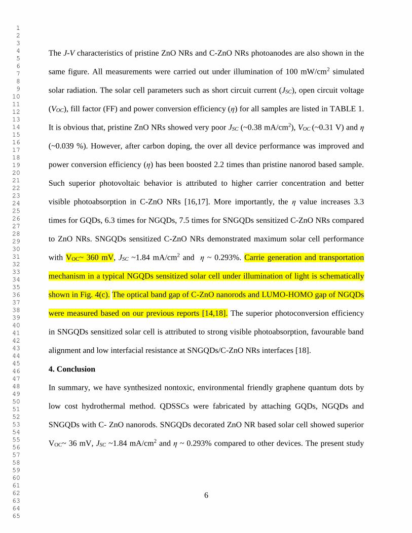
The J-V characteristics of pristine ZnO NRs and C-ZnO NRs photoanodes are also shown in the
same figure. All measurements were carried out under illumination of 100 mW/cm2 simulated
solar radiation. The solar cell parameters such as short circuit current (JSC), open circuit voltage
(VOC), fill factor (FF) and power conversion efficiency (η) for all samples are listed in TABLE 1.
It is obvious that, pristine ZnO NRs showed very poor JSC (~0.38 mA/cm2), VOC (~0.31 V) and η
(~0.039 %). However, after carbon doping, the over all device performance was improved and
power conversion efficiency (η) has been boosted 2.2 times than pristine nanorod based sample.
Such superior photovoltaic behavior is attributed to higher carrier concentration and better
visible photoabsorption in C-ZnO NRs [16,17]. More importantly, the η value increases 3.3
times for GQDs, 6.3 times for NGQDs, 7.5 times for SNGQDs sensitized C-ZnO NRs compared
to ZnO NRs. SNGQDs sensitized C-ZnO NRs demonstrated maximum solar cell performance
with VOC~ 360 mV, JSC ~1.84 mA/cm2 and η ~ 0.293%. Carrie generation and transportation
mechanism in a typical NGQDs sensitized solar cell under illumination of light is schematically
shown in Fig. 4(c). The optical band gap of C-ZnO nanorods and LUMO-HOMO gap of NGQDs
were measured based on our previous reports [14,18]. The superior photoconversion efficiency
in SNGQDs sensitized solar cell is attributed to strong visible photoabsorption, favourable band
alignment and low interfacial resistance at SNGQDs/C-ZnO NRs interfaces [18].
4. Conclusion
In summary, we have synthesized nontoxic, environmental friendly graphene quantum dots by
low cost hydrothermal method. QDSSCs were fabricated by attaching GQDs, NGQDs and
SNGQDs with C- ZnO nanorods. SNGQDs decorated ZnO NR based solar cell showed superior
VOC~ 36 mV, JSC ~1.84 mA/cm2 and η ~ 0.293% compared to other devices. The present study
1 2 3 4 5 6 7 8 9 10 11 12 13 14 15 16 17 18 19 20 21 22 23 24 25 26 27 28 29 30 31 32 33 34 35 36 37 38 39 40 41 42 43 44 45 46 47 48 49 50 51 52 53 54 55 56 57 58 59 60 61 62 63 64 65

7
demonstrated the potential use of GQDs as new kinds of metal free green photosensitizer for
QDSSC application.
Acknowledgements
This present research work was funded by CSIR Extramural Research Grant, Government of
India.
References
[1] Bauhuis G J, Mulder P, Haverkamp E J, Huijben J C C M and Schermer J J 2009 Sol. Energ.
Mat. Sol. Cells 93 1488.
[2] Cook T R, Dogutan D K, Reece S Y, Surendranath Y, Teets and Nocera D G 2010 Chem Rev
110 6474.
[3] Lewis N S 2007 Science 115 798.
[4] Huang F, Hou J, Zhang Q, Wang Y, Masse R C, Peng S, Wang H, Liu J and Cao G 2016
Nano Energy 26 114.
[5] Wang J, Mora-Sero I, Pan Z, Zhao K, Zhang H, Feng Y, Yang G, Zhong X and Bisquert J
2013 J Am Chem Soc 135 15913.
[6] Jiao S, Wang J, Shen Q, Li Y and Zhong X 2016 J Mater Chem A 4 7214.
[7] Yang J, Wang J, Zhao K, Izuishi T, Li Y, Shen Q and Zhong X 2015 J Phys Chem C 119
28800.
[8] Du J, Du Z, Hu J S, Pan Z, Shen Q, Sun J, Long D, Dong H, L Sun, Zhong X and Wan L J
2016 J Am Chem Soc 138 4201.
[9] Zheng X T, Ananthanarayanan A, Luo K Q and P Chen 2016 Small 11 1620.
[10] Qu D, Zheng M, Du P, Zhou Y, Zhang L, Li D, Tan H, Zhao Z, Xie Z and Z Sun 2013
Nanoscale 5 12272.
[11] Fan Z, Li Y, Li X, Fan L, Zhou S, Fang D and Yang S 2014 Carbon 70 149.
[12] Barman M K, Jana B, Bhattacharyya S and Patra A 2014 J Phys Chem C 118 20034.
[13] Majumder T and Mondal S P 2016 J Electroanal Chem 769 48.
[14] Majumder T, Debnath K, Dhar S, Hmar J J L and Mondal S P 2016 Energy Technol 4
950.
[15] Majumder T, Dhar S, Debnath K and Mondal S P 2017 Mater Res Bul 93 214.
[16] Zulkifli Z, Subramanian M, Tsuchiya T, Rosmi M S, Ghosh P, Kalita G and Tanemura
M 2014 RSC Adv 4 64763.
[17] Xie S, Lu X, Zhai T, Li W, Yu M, Liang C and Tong Y 2012 J Mater Chem 22 14272.
[18] Majumder T, Dhar S, Chakraborty P, and Mondal S P 2018 Chemistry Select 3 4082.
1 2 3 4 5 6 7 8 9 10 11 12 13 14 15 16 17 18 19 20 21 22 23 24 25 26 27 28 29 30 31 32 33 34 35 36 37 38 39 40 41 42 43 44 45 46 47 48 49 50 51 52 53 54 55 56 57 58 59 60 61 62 63 64 65

8
Figures:
Fig 1: Plane view TEM images of (a) GQDs, (b) NGQDs and (c) SNGQDs High resolution
TEM micrographs are presented at the insets Full scan XPS spectra of (d) GQDs, (e) NGQDs
and (f) SNGQDs
100 200 300 400 500 600
Si 2s
Si 2p Na Auger
O 1s
Inte
ns
ity
(a
.u)
Binding Energy (eV)
GQDs
C 1s
(d)
100 200 300 400 500 600
Si 2s
Si 2pN 1s
O 1s
Inte
ns
ity
(a
.u)
Binding Energy (eV)
NGQDs
C 1s
(e)
100 200 300 400 500 600
S 2p
Si 2s
Si 2pN 1s
O 1s
Inte
nsit
y (
a.u
)Binding Energy (eV)
SNGQDs
C 1s
(f)
(a) (b) (c) 0.34 nm 0.34 nm 0.34 nm
1 2 3 4 5 6 7 8 9 10 11 12 13 14 15 16 17 18 19 20 21 22 23 24 25 26 27 28 29 30 31 32 33 34 35 36 37 38 39 40 41 42 43 44 45 46 47 48 49 50 51 52 53 54 55 56 57 58 59 60 61 62 63 64 65

9
Fig. 2: UV-Visible absorption spectrum of GQD, NGQD and SNGQD
200 300 400 500 600 700
Wavelength (nm)
GQDs
Inte
ns
ity
(a
.u)
NGQDs
SNGQDs
1 2 3 4 5 6 7 8 9 10 11 12 13 14 15 16 17 18 19 20 21 22 23 24 25 26 27 28 29 30 31 32 33 34 35 36 37 38 39 40 41 42 43 44 45 46 47 48 49 50 51 52 53 54 55 56 57 58 59 60 61 62 63 64 65

10
Fig 3: (a) SEM micrographs of (a) ZnO and (b) C-ZnO nanorods Chemical mapping of both
nanorods shown at insets XPS full scan spectra of (c) ZnO and (d) C-ZnO nanorods C 1s
electronic peaks before and after surface cleaning are presented at the insets.
0 200 400 600 800 1000
Zn
3d
O1
s
Zn
LL
MZ
n L
LM
Zn
LL
M
Zn
LL
M
Zn
2p
Zn
2p
C1
sZn
3s
Inte
nsit
y (
a.u
)
Binding Energy (eV)
ZnO Nanorods
Zn
3p
0 200 400 600 800 1000 1200
Zn
3d
Zn
3s
O1
s
Zn
LL
MZ
n L
LM
Zn
LL
M
Zn
LL
M
Zn
2p
Zn
2p
C1
s
In
ten
sit
y (
a.u
)
Binding Energy (eV)
C-ZnO Nanorods
Zn
3p
282 284 286 288 290
After
Surface Cleaning
Binding Energy (eV)
Inte
ns
ity
(a
.u)
Before
Surface Cleaning
C1s
282 284 286 288 290
C1s
After
Surface Cleaning
Binding Energy (eV)
Inte
nsit
y (
a.u
)
Before
Surface Cleaning
C1s
Zinc Zinc
Oxygen Oxygen
Carbon Carbon
(a) (b)
(c) (d)
5 µm 5 µm
1 2 3 4 5 6 7 8 9 10 11 12 13 14 15 16 17 18 19 20 21 22 23 24 25 26 27 28 29 30 31 32 33 34 35 36 37 38 39 40 41 42 43 44 45 46 47 48 49 50 51 52 53 54 55 56 57 58 59 60 61 62 63 64 65

11
Fig 4: (a) Schematic representation of a typical GQDs sensitized C-ZnO NRs based QDSSC. (b)
Current density vs voltage (J-V) characteristics of pristine ZnO NRs, C-ZnO NRs, GQDs/C-ZnO
NRs, NGQDs/C-ZnO NRs and SNGQDs/C-ZnO NRs based QDSSCs under 100 mW/cm2 white
light illumination (AM 15). (c) Schematic representation of charge transportation and separation
mechanism in a typical NGQDs sensitized solar cell.
0.0 0.1 0.2 0.3 0.4
0.0
-0.5
-1.0
-1.5
-2.0
Cu
rren
t D
en
sit
y (
mA
/cm
2)
Voltage (V)
ZnO NRs
C-ZnO NRs
GQDs/C-ZnO NRs
NGQDs/C-ZnO NRs
SNGQDs/C-ZnO NRs
(b)
(a)
(c)
1 2 3 4 5 6 7 8 9 10 11 12 13 14 15 16 17 18 19 20 21 22 23 24 25 26 27 28 29 30 31 32 33 34 35 36 37 38 39 40 41 42 43 44 45 46 47 48 49 50 51 52 53 54 55 56 57 58 59 60 61 62 63 64 65

12
TABLE 1: Solar cell parameters (VOC, JSC, η) of GQDs sensitized QDSSCs devices
Photoanodes VOC
(mV)
JSC
(mA/cm2)
FF
(%)
ɳ
(%)
FTO/ZnO NRs 310 0.38 33.95 0.039
FTO/C-ZnO NRs 380 0.51 44.37 0.086
FTO/GQDs sensitized C-ZnO NRs 370 0.87 40.38 0.129
FTO/NGQDs sensitized C-ZnO NRs 370 1.51 42.95 0.247
FTO/SNGQDs sensitized C-ZnO NRs 360 1.84 45.28 0.293
1 2 3 4 5 6 7 8 9 10 11 12 13 14 15 16 17 18 19 20 21 22 23 24 25 26 27 28 29 30 31 32 33 34 35 36 37 38 39 40 41 42 43 44 45 46 47 48 49 50 51 52 53 54 55 56 57 58 59 60 61 62 63 64 65