Embed Size (px)
Citation preview
Instruction manual part number 385008
Revision G - July 2017
Series 385
Instruction Manual
Granville-Phillips® Series 385 Convectron® ATM Vacuum Gauge Module with DeviceNetTM

.
Instruction Manual
Series 385
This Instruction Manual is for use with all Granville-Phillips Series 385 Convectron ATM Vacuum Gauge Modules with DeviceNet interface. A list of applicable catalog numbers is provided on the following page.
Granville-Phillips® Series 385 Convectron® ATM Vacuum Gauge Module with DeviceNetTM
© 2017 MKS Instruments, Inc. All rights reserved.Granville-Phillips® and Convectron® are registered trademarks, and mksinstTM is a trademark of MKA Instruments, Inc. All other trademarks and registered trademarks are the properties of their respective owners.
Customer Service / Technical Support:
MKS Pressure and Vacuum Measurement SolutionsMKS Instruments, Inc.6450 Dry Creek ParkwayLongmont, Colorado 80503 USATel: 303-652-4400Fax: 303-652-2844Email: [email protected]
MKS Corporate HeadquartersMKS Instruments, Inc.2 Tech Drive, Suite 201Andover, MA 01810 USATel: 978-645-5500Fax: 978-557-5100Email: [email protected]
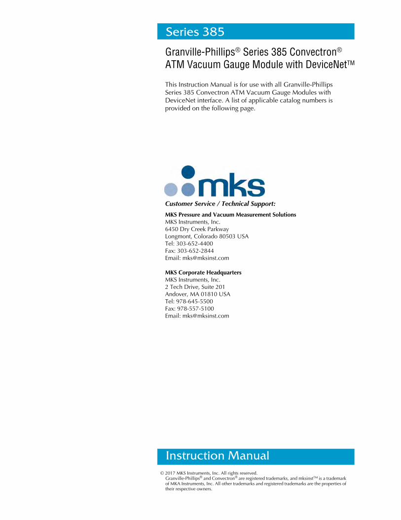
Granville-Phillips® Series 385 Convectron® ATMVacuum Gauge Module with DeviceNetTM Interface
Catalog numbers for Series 385 Convectron ATM ModulesPower supply and cable are not included.
385 Module with DeviceNet - with digital display:
4 setpoint relays, gold-plated tungsten 385007 - G # - #Convectron, NW16KF fitting, Torr, 10 bytes communication
4 setpoint relays, gold-plated tungsten 385011 - G # - #Convectron, NW16KF fitting, Millibar, 18 bytes communication
Flange/Fitting:
1/4 inch VCR-type female QNW16KF DNW25KF E
Measurement Units:
Torr Tmbar Mpascal P
VCR is a registered trademark of Swagelok Company
Convectron®ATM Module Instruction Manual - 385008 5
Table of Contents
Chapter 1 Safety & Introduction . . . . . . . . . . . . . . . . . . . . . . . . . . . . . . . . . 71.1 About These Instructions . . . . . . . . . . . . . . . . . . . . . . . . . . . 71.2 Caution and Warning Statements . . . . . . . . . . . . . . . . . . . . 71.3 Reading and Following Instructions . . . . . . . . . . . . . . . . . . 71.4 Definitions of Terms . . . . . . . . . . . . . . . . . . . . . . . . . . . . . . 81.5 General Safety Guidelines . . . . . . . . . . . . . . . . . . . . . . . . . . 101.6 Overpressure Conditions and Explosive Environments . . . . 101.7 Equipment Grounding . . . . . . . . . . . . . . . . . . . . . . . . . . . . . 121.8 Damage Requiring Service . . . . . . . . . . . . . . . . . . . . . . . . . 121.9 Customer Service Guidelines . . . . . . . . . . . . . . . . . . . . . . . 131.10 Warranty Information . . . . . . . . . . . . . . . . . . . . . . . . . . . . . 141.11 FCC Verification . . . . . . . . . . . . . . . . . . . . . . . . . . . . . . . . . 14
Chapter 2 Installation . . . . . . . . . . . . . . . . . . . . . . . . . . . . . . . . . . . . . . . . . . 152.1 Module Components . . . . . . . . . . . . . . . . . . . . . . . . . . . . . 152.2 Installation Procedure . . . . . . . . . . . . . . . . . . . . . . . . . . . . . 15
Step 1 Install pressure relief devices . . . . . . . . . . . . . . . . 15Step 2 Locate and orient the module . . . . . . . . . . . . . . . . 15
Location of the Module . . . . . . . . . . . . . . . . . . . . 15Orientation of the Module . . . . . . . . . . . . . . . . . . 16
Step 3 Attach the module to the vacuum chamber . . . . . 171/8 NPT Pipe Thread . . . . . . . . . . . . . . . . . . . . . . 17VCR Type Fitting . . . . . . . . . . . . . . . . . . . . . . . . . 17KF Flange . . . . . . . . . . . . . . . . . . . . . . . . . . . . . . . 17ConFlat Flange . . . . . . . . . . . . . . . . . . . . . . . . . . . 17
Step 4 Assemble and connect the wiring . . . . . . . . . . . . . 17DeviceNet Wiring . . . . . . . . . . . . . . . . . . . . . . . . 18Output and Relay Wiring . . . . . . . . . . . . . . . . . . . 18Grounding . . . . . . . . . . . . . . . . . . . . . . . . . . . . . . 18
Step 5 Configure the setpoint relays for the application . . 19Step 6 Calibrate the Convectron gauge . . . . . . . . . . . . . . 19
Atmospheric Pressure Calibration . . . . . . . . . . . . . 19Vacuum Pressure Calibration . . . . . . . . . . . . . . . . 19
2.3 Eliminating Radio Frequency Interference . . . . . . . . . . . . . . 20
Chapter 3 Operation Overview . . . . . . . . . . . . . . . . . . . . . . . . . . . . . . . . . . 213.1 Preparing for Pressure Measurement . . . . . . . . . . . . . . . . . . 213.2 Gas Type . . . . . . . . . . . . . . . . . . . . . . . . . . . . . . . . . . . . . . 213.3 Preparing For Convectron Gauge Operation . . . . . . . . . . . . 213.4 Understanding Convectron Gauge Pressure Measurement . 21
Gases Other Than Nitrogen or Air . . . . . . . . . . . . . . . . . . . . 22Examples . . . . . . . . . . . . . . . . . . . . . . . . . . . . . . . . . . . . . . 23
3.5 Adjustment of Convectron Gauge Zero and Atmospheric Pressure Indications . . . . . . . . . . . . . . . . . . . . . . . . . . . . . 30Calibrate the Vacuum Reading . . . . . . . . . . . . . . . . . . . . . . 30Calibrate the Atmosphere Reading . . . . . . . . . . . . . . . . . . . 30
3.6 Special Considerations for Convectron Gauge Use Below 10-3 Torr . . . . . . . . . . . . . . . . . . . . . . . . . . . . 31
Chapter 4 DeviceNet Operation . . . . . . . . . . . . . . . . . . . . . . . . . . . . . . . . . . 334.1 Preparing to Operate the DeviceNet Module . . . . . . . . . . . 334.2 Module Front and Back Panels . . . . . . . . . . . . . . . . . . . . . . 334.3 LED Status Indicator . . . . . . . . . . . . . . . . . . . . . . . . . . . . . . 354.4 NET and MOD LEDs . . . . . . . . . . . . . . . . . . . . . . . . . . . . . . 354.5 Performance with DeviceNet Protocol . . . . . . . . . . . . . . . . 364.6 DeviceNet Protocol for the Convectron ATM Module . . . . . 374.7 Operational Tasks . . . . . . . . . . . . . . . . . . . . . . . . . . . . . . . . 37
Table of Contents
6 Convectron®ATM Module Instruction Manual - 385008
4.8 DeviceNet Switches and Indicators . . . . . . . . . . . . . . . . . . . 37Address Switches . . . . . . . . . . . . . . . . . . . . . . . . . . . . . . . . 37Rate Switch . . . . . . . . . . . . . . . . . . . . . . . . . . . . . . . . . . . . . 38
4.9 DeviceNet Communication Configuration . . . . . . . . . . . . . 394.10 Pressure Units and Values . . . . . . . . . . . . . . . . . . . . . . . . . . 40
Set or Get Pressure Unit . . . . . . . . . . . . . . . . . . . . . . . . . . . 41Data Conversion . . . . . . . . . . . . . . . . . . . . . . . . . . . . . . . . . 41Get Vacuum Pressure or Differential Pressure . . . . . . . . . . . 41
4.11 Process Control Relays . . . . . . . . . . . . . . . . . . . . . . . . . . . . 43Get Relay Setpoints . . . . . . . . . . . . . . . . . . . . . . . . . . . . . . . 47Get Enable/Disable Status of Relays . . . . . . . . . . . . . . . . . . 48Get Activation or Deactivation Status of Relays . . . . . . . . . . 48Get Relay Hysteresis . . . . . . . . . . . . . . . . . . . . . . . . . . . . . . 48Get Relay Assignments . . . . . . . . . . . . . . . . . . . . . . . . . . . . 49
4.12 Calibrate Convectron Gauge at Atmospheric Pressure . . . . . 494.13 Calibrate Convectron Gauge at Vacuum Pressure . . . . . . . . 494.14 Calibrate Differential Pressure Sensor Zero . . . . . . . . . . . . . 504.15 Reset Module to Power-up State . . . . . . . . . . . . . . . . . . . . . 504.16 Get Firmware Version . . . . . . . . . . . . . . . . . . . . . . . . . . . . . 504.17 Factory Defaults . . . . . . . . . . . . . . . . . . . . . . . . . . . . . . . . . 514.18 DeviceNet Error Codes . . . . . . . . . . . . . . . . . . . . . . . . . . . . 51
Using Polled I/O . . . . . . . . . . . . . . . . . . . . . . . . . . . . . . . . . 51Using Explicit Messages . . . . . . . . . . . . . . . . . . . . . . . . . . . 51
Chapter 5 Service & Maintenance . . . . . . . . . . . . . . . . . . . . . . . . . . . . . . . 555.1 Customer Service . . . . . . . . . . . . . . . . . . . . . . . . . . . . . . . . 55
Damage Requiring Service . . . . . . . . . . . . . . . . . . . . . . . . . 555.2 Troubleshooting . . . . . . . . . . . . . . . . . . . . . . . . . . . . . . . . . 55
Precautions . . . . . . . . . . . . . . . . . . . . . . . . . . . . . . . . . . . . . 55Symptoms, Causes, and Solutions . . . . . . . . . . . . . . . . . . . . 56
5.3 DeviceNet Error Codes . . . . . . . . . . . . . . . . . . . . . . . . . . . . 57Using Polled I/O . . . . . . . . . . . . . . . . . . . . . . . . . . . . . . . . . 57Using Explicit Messages . . . . . . . . . . . . . . . . . . . . . . . . . . . 57
5.4 Convectron Gauge Test . . . . . . . . . . . . . . . . . . . . . . . . . . . . 575.5 Convectron Gauge Removal and Replacement . . . . . . . . . . 58
Remove the Convectron Gauge . . . . . . . . . . . . . . . . . . . . . 58Install the Replacement Convectron Gauge . . . . . . . . . . . . . 59
5.6 Returning a Damaged Module . . . . . . . . . . . . . . . . . . . . . . 60
Chapter 6 Specifications . . . . . . . . . . . . . . . . . . . . . . . . . . . . . . . . . . . . . . . . 61
Chapter 7 Theory of Operation . . . . . . . . . . . . . . . . . . . . . . . . . . . . . . . . . . 657.1 Piezo Resistive Diaphragm Sensor . . . . . . . . . . . . . . . . . . . 657.2 Convectron Heat-loss Pirani Gauge . . . . . . . . . . . . . . . . . . 657.3 Wheatstone Bridge Circuit Description . . . . . . . . . . . . . . . . 65
Chapter 8 Messaging Summary . . . . . . . . . . . . . . . . . . . . . . . . . . . . . . . . . 67
Index . . . . . . . . . . . . . . . . . . . . . . . . . . . . . . . . . . . . . . . . . . . . . . . . . . . . . . . . . . . . . . . . . . . . . . . . . . . . . 75
Convectron®ATM Module Instruction Manual - 385008 7
Chapter 1 Safety & Introduction
1.1 About These Instructions
These instructions explain how to install, operate, and maintain the Granville-Phillips® Convectron® ATM vacuum gauge module.
• This chapter explains caution and warning statements, which must be adhered to at all times; explains your responsibility for reading and following all instructions; defines the terms that are used throughout this instruction manual; and tells you how to contact customer service.
• Chapter 2 explains how to install the module.
• Chapter 3 is an operational overview of the module.
• Chapter 4 explains how to operate the DeviceNetTM version of the module, which has four programmable setpoint relays.
• Chapter 5 explains troubleshooting; Convectron gauge testing, removal and replacement; and module return procedures.
• Chapter 6 provides specifications for the module.
• Chapter 7 explains terminology and explains how the Convectron convection-enhanced Pirani heat-loss gauge and Piezo resistive diaphragm sensor measure pressure.
• Chapter 8 summarizes DeviceNet polled I/O and explicit messages.
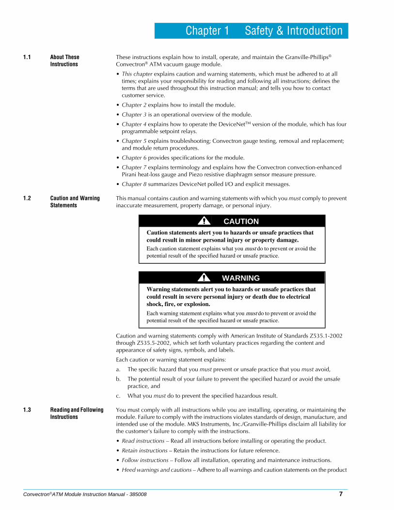
1.2 Caution and Warning Statements
This manual contains caution and warning statements with which you must comply to prevent inaccurate measurement, property damage, or personal injury.
Caution and warning statements comply with American Institute of Standards Z535.1-2002 through Z535.5-2002, which set forth voluntary practices regarding the content and appearance of safety signs, symbols, and labels.
Each caution or warning statement explains:
a. The specific hazard that you must prevent or unsafe practice that you must avoid,
b. The potential result of your failure to prevent the specified hazard or avoid the unsafe practice, and
c. What you must do to prevent the specified hazardous result.
1.3 Reading and Following Instructions
You must comply with all instructions while you are installing, operating, or maintaining the module. Failure to comply with the instructions violates standards of design, manufacture, and intended use of the module. MKS Instruments, Inc./Granville-Phillips disclaim all liability for the customer's failure to comply with the instructions.
• Read instructions – Read all instructions before installing or operating the product.
• Retain instructions – Retain the instructions for future reference.
• Follow instructions – Follow all installation, operating and maintenance instructions.
• Heed warnings and cautions – Adhere to all warnings and caution statements on the product
CAUTIONCaution statements alert you to hazards or unsafe practices that could result in minor personal injury or property damage.Each caution statement explains what you must do to prevent or avoid the potential result of the specified hazard or unsafe practice.
WARNINGWarning statements alert you to hazards or unsafe practices that could result in severe personal injury or death due to electrical shock, fire, or explosion.
Each warning statement explains what you must do to prevent or avoid the potential result of the specified hazard or unsafe practice.
Chapter 1
8 Convectron®ATM Module Instruction Manual - 385008
and in these instructions.
• Parts and accessories – Install only those replacement parts and accessories that are recommended by Granville-Phillips. Substitution of parts is hazardous.
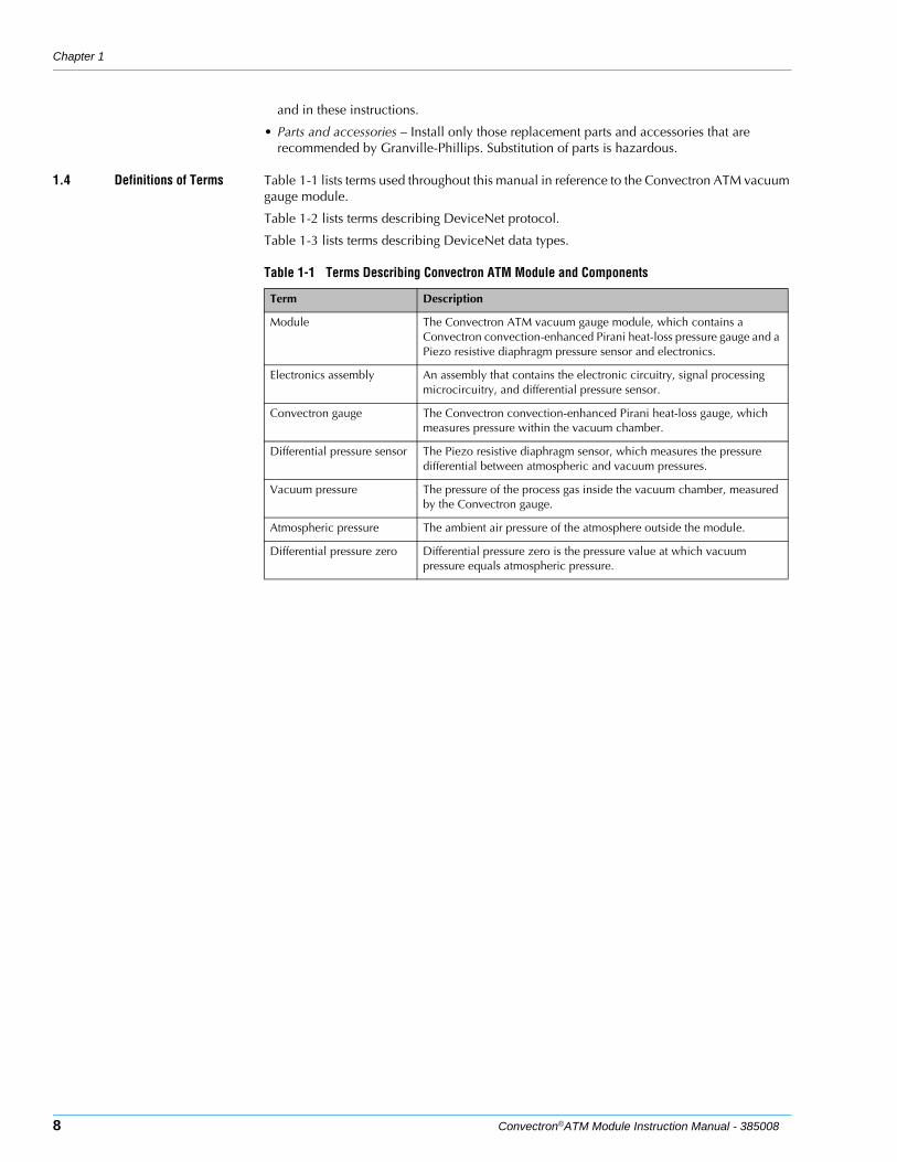
1.4 Definitions of Terms Table 1-1 lists terms used throughout this manual in reference to the Convectron ATM vacuum gauge module.
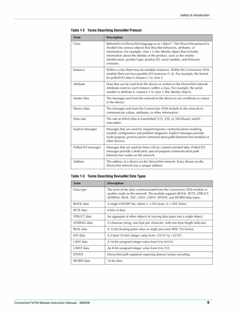
Table 1-2 lists terms describing DeviceNet protocol.
Table 1-3 lists terms describing DeviceNet data types.
Table 1-1 Terms Describing Convectron ATM Module and Components
Term Description
Module The Convectron ATM vacuum gauge module, which contains a Convectron convection-enhanced Pirani heat-loss pressure gauge and a Piezo resistive diaphragm pressure sensor and electronics.
Electronics assembly An assembly that contains the electronic circuitry, signal processing microcircuitry, and differential pressure sensor.
Convectron gauge The Convectron convection-enhanced Pirani heat-loss gauge, which measures pressure within the vacuum chamber.
Differential pressure sensor The Piezo resistive diaphragm sensor, which measures the pressure differential between atmospheric and vacuum pressures.
Vacuum pressure The pressure of the process gas inside the vacuum chamber, measured by the Convectron gauge.
Atmospheric pressure The ambient air pressure of the atmosphere outside the module.
Differential pressure zero Differential pressure zero is the pressure value at which vacuum pressure equals atmospheric pressure.
Safety & Introduction
Convectron®ATM Module Instruction Manual - 385008 9
Table 1-2 Terms Describing DeviceNet Protocol
Term Description
Class Referred to in DeviceNet language as an “object”. The DeviceNet protocol is divided into various objects that describe behaviors, attributes, or information. For example, class 1 is the identity object that includes information about the identity of the product, such as the vendor identification, product type, product ID, serial number, and firmware revisions.
Instance Within a class there may be multiple instances. Within the Convectron ATM module there are four possible I/O instances (1–4). For example, the format for polled I/O data is instance 2 in class 5.
Attribute Data that can be read from the device or written to the DeviceNet network. Attributes exist for each instance within a class. For example, the serial number is attribute 6, instance 1 in class 1 (the identity object).
Master data The messages sent from the network to the device to set conditions or values in the device.
Device data The messages sent from the Convectron ATM module to the network to communicate values, attributes, or other information.
Data rate The rate at which data is transmitted (125, 250, or 500 kbaud, switch selectable).
Explicit messages Messages that are used for request/response communications enabling module configuration and problem diagnosis. Explicit messages provide multi-purpose, point-to-point communication paths between two modules or other devices.
Polled I/O messages Messages that are used for time-critical, control-oriented data. Polled I/O messages provide a dedicated, special-purpose communication path between two nodes on the network.
Address The address of a device on the DeviceNet network. Every device on the DeviceNet network has a unique address.
Table 1-3 Terms Describing DeviceNet Data Types
Term Description
Data type The form of the data communicated from the Convectron ATM module or another node on the network. The module supports BOOL, BYTE, STRUCT, SSTRING, REAL, INT, UINT, USINT, EPATH, and WORD data types.
BOOL data A single ON/OFF bit, where 1 = ON (true), 0 = OFF (false).
BYTE data 8-bits of data.
STRUCT data An aggregate of other objects of varying data types into a single object.
SSTRING data A character string, one byte per character, with one byte length indicator.
REAL data A 32-bit floating point value in single precision IEEE 754 format.
INT data A 2-byte (16-bit) integer value from –32767 to +32767.
UINT data A 16-bit unsigned integer value from 0 to 65535.
USINT data An 8-bit unsigned integer value from 0 to 255.
EPATH DeviceNet path segments requiring abstract syntax encoding.
WORD data 16-bit data.

Chapter 1
10 Convectron®ATM Module Instruction Manual - 385008
1.5 General Safety Guidelines These instructions do not and cannot provide for every contingency that may arise in connection with the installation, operation, or maintenance of this product. If you require further assistance, contact Granville-Phillips at the address on the title page of this manual.This product is designed and tested to offer reasonably safe service provided it is installed, operated, and serviced in strict accordance with these safety instructions.
These safety precautions must be observed during all phases of operation, installation, and service of this product. Failure to comply with these precautions or with specific warnings elsewhere in this manual violates safety standards of design, manufacture, and intended use of the instrument. MKS Instruments, Inc. disclaims all liability for the customer's failure to comply with these requirements.
1.6 Overpressure Conditions and Explosive Environments
WARNINGFailure to comply with these instructions may result in serious personal injury, including death, or property damage.
CAUTIONThe service and repair information in this manual is for the use of Qualified Service Personnel. To avoid shock, do not perform any procedures in this manual or perform any servicing on this product unless you are qualified to do so.
WARNINGTo reduce the risk of fire or electric shock, do not expose this product to rain or moisture.
WARNINGObjects and Liquid Entry − Never push objects of any kind into this product through openings as they may touch dangerous voltage points or short out parts that could result in a fire or electric shock. Be careful not to spill liquid of any kind onto the products.
WARNINGDo not substitute parts or modify instrument.Because of the danger of introducing additional hazards, do not install substitute parts or perform any unauthorized modification to the product. Return the product to a service facility designated by Granville−Phillips for service and repair to ensure that safety features are maintained. Do not use this product if it has unauthorized modifications.
WARNINGSeries 275/385 Gauges should not be used above 1000 Torr (1333 mbar, 133 kPa, 19 psi) true pressure.

Safety & Introduction
Convectron®ATM Module Instruction Manual - 385008 11
Convectron gauges are furnished calibrated for N2. They also measure the pressure of air correctly within the accuracy of the instrument. Do not attempt to use a Convectron gauge calibrated for N2 to measure or control the pressure of other gases such as argon or CO2, unless accurate conversion data for N2 to the other gas is properly used.
A pressure relief valve should be installed in the system if the possibility of exceeding 1000 Torr (1333 mbar, 133 kPa, 19 psi) exists.
Suppliers of pressure relief valves and pressure relief disks can be located via internet search.
Confirm that these safety devices are properly installed before installing the product. In addition, check that:
a. The proper gas cylinders are installed,
b. Gas cylinder valve positions are correct on manual systems, and
c. The automation is correct on automated gas delivery systems.
It is the installer's responsibility to ensure that the automatic signals provided by the product are always used in a safe manner. Carefully check manual operation of the system and the set
WARNINGIf used improperly, Convectron Gauges can supply misleading pressure indications that can result in dangerous overpressure conditions within the system. If accurate conversion data is not used, or is improperly used, a potential overpressure explosion hazard can be created under certain conditions.
WARNINGUsing the N2 calibration to pressurize a vacuum system above about 1 Torr with certain other gases can cause dangerously high pressures which may cause explosion of the system.
WARNINGInstall suitable devices that will limit the pressure to the level that the vacuum system can safely withstand. In addition, install suitable pressure relief valves or rupture disks that will release pressure at a level considerably below the pressure that the system can safely withstand.
WARNINGDo not operate in an explosive atmosphere.
Do not operate the product in the presence of flammable gases or fumes.
Operation of any electrical instrument in such an environment constitutes a definite safety hazard.
Do not use the product to measure the pressure of explosive or combustible gases or gas mixtures. The sensor wire of the Convectron Gauge normally operates at only 125 ˚C, but it is possible that Controller malfunction can raise the sensor temperature above the ignition temperature of combustible mixtures.
Danger of explosion or inadvertent venting to atmosphere exists on all vacuum systems which incorporate gas sources or involve processes capable of pressurizing the system above safe limits.
12 Convectron®ATM Module Instruction Manual - 385008
point programming before switching to automatic operation.
Where an equipment malfunction could cause a hazardous situation, always provide for fail-safe operation. As an example, in an automatic backfill operation where a malfunction might cause high internal pressures, provide an appropriate pressure relief device.
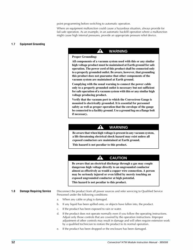
1.7 Equipment Grounding
1.8 Damage Requiring Service Disconnect the product from all power sources and refer servicing to Qualified Service Personnel under the following conditions:
a. When any cable or plug is damaged.
b. If any liquid has been spilled onto, or objects have fallen into, the product.
c. If the product has been exposed to rain or water.
d. If the product does not operate normally even if you follow the operating instructions. Adjust only those controls that are covered by the operation instructions. Improper adjustment of other controls may result in damage and will often require extensive work by a qualified technician to restore the product to its normal operation.
e. If the product has been dropped or the enclosure has been damaged.
WARNINGProper Grounding:
All components of a vacuum system used with this or any similar high voltage product must be maintained at Earth ground for safe operation. The power cord of this product shall be connected only to a properly grounded outlet. Be aware, however, that grounding this product does not guarantee that other components of the vacuum system are maintained at Earth ground.
Complying with the usual warning to connect the power cable only to a properly grounded outlet is necessary but not sufficient for safe operation of a vacuum system with this or any similar high voltage producing product.
Verify that the vacuum port to which the Convectron Gauge is mounted is electrically grounded. It is essential for personnel safety as well as proper operation that the envelope of the gauge be connected to a facility ground. Use a ground lug on a flange bolt if necessary.
WARNINGBe aware that when high voltage is present in any vacuum system, a life threatening electrical shock hazard may exist unless all exposed conductors are maintained at Earth ground.
This hazard is not peculiar to this product.
CAUTIONBe aware that an electrical discharge through a gas may couple dangerous high voltage directly to an ungrounded conductor almost as effectively as would a copper wire connection. A person may be seriously injured or even killed by merely touching an exposed ungrounded conductor at high potential.This hazard is not peculiar to this product.
Safety & Introduction
Convectron®ATM Module Instruction Manual - 385008 13
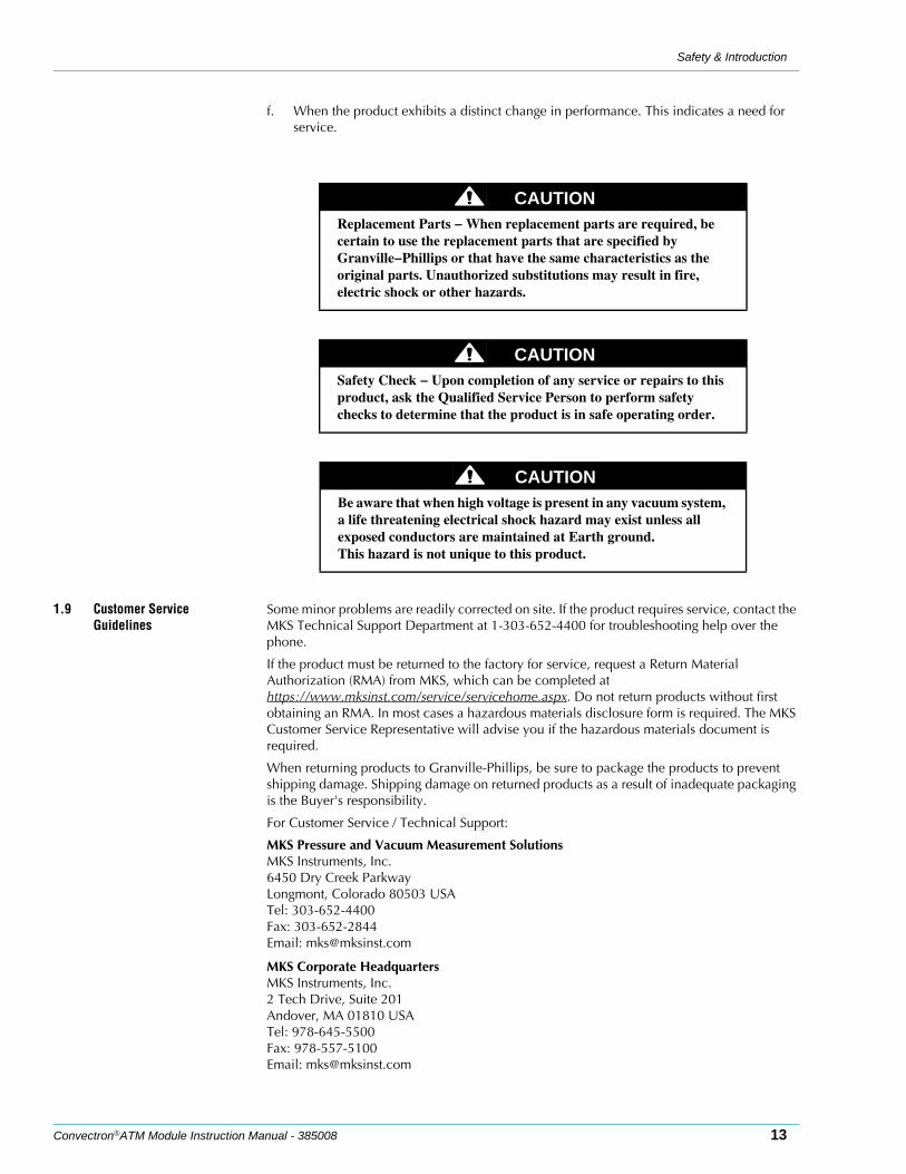
f. When the product exhibits a distinct change in performance. This indicates a need for service.
1.9 Customer Service Guidelines
Some minor problems are readily corrected on site. If the product requires service, contact the MKS Technical Support Department at 1-303-652-4400 for troubleshooting help over the phone.
If the product must be returned to the factory for service, request a Return Material Authorization (RMA) from MKS, which can be completed at https://www.mksinst.com/service/servicehome.aspx. Do not return products without first obtaining an RMA. In most cases a hazardous materials disclosure form is required. The MKS Customer Service Representative will advise you if the hazardous materials document is required.
When returning products to Granville-Phillips, be sure to package the products to prevent shipping damage. Shipping damage on returned products as a result of inadequate packaging is the Buyer's responsibility.
For Customer Service / Technical Support:
MKS Pressure and Vacuum Measurement SolutionsMKS Instruments, Inc.6450 Dry Creek ParkwayLongmont, Colorado 80503 USATel: 303-652-4400Fax: 303-652-2844Email: [email protected]
MKS Corporate HeadquartersMKS Instruments, Inc.2 Tech Drive, Suite 201Andover, MA 01810 USATel: 978-645-5500Fax: 978-557-5100Email: [email protected]
CAUTIONReplacement Parts − When replacement parts are required, be certain to use the replacement parts that are specified by Granville−Phillips or that have the same characteristics as the original parts. Unauthorized substitutions may result in fire, electric shock or other hazards.
CAUTIONSafety Check − Upon completion of any service or repairs to this product, ask the Qualified Service Person to perform safety checks to determine that the product is in safe operating order.
CAUTIONBe aware that when high voltage is present in any vacuum system, a life threatening electrical shock hazard may exist unless all exposed conductors are maintained at Earth ground.This hazard is not unique to this product.
Chapter 1
14 Convectron®ATM Module Instruction Manual - 385008
1.10 Warranty Information MKS Instruments, Inc. provides an eighteen (18) month warranty from the date of shipment for new Granville-Phillips Products. The MKS Instruments, Inc. General Terms and Conditions of Sale provides the complete and exclusive warranty for Granville-Phillips products. This document may be located on our web site at www.mksinst.com, or may be obtained by contacting an MKS Customer Service Representative.
1.11 FCC Verification This equipment has been tested and found to comply with the limits for a Class A digital device, pursuant to Part 15 of the FCC Rules. These limits are designed to provide reasonable protection against harmful interference when the equipment is operated in a commercial environment. This equipment generates, uses, and can radiate radio frequency energy and, if not installed and used in accordance with this instruction manual, may cause harmful interference to radio communications. However, there is no guarantee that interference will not occur in a particular installation. Operation of this equipment in a residential area is likely to cause harmful interference in which case the user will be required to correct the interference at his own expense. If this equipment does cause harmful interference to radio or television reception, which can be determined by turning the equipment off and on, the user is encouraged to try to correct the interference by one or more of the following measures:
• Reorient or relocate the receiving antenna.
• Increase the separation between the equipment and the receiver.
• Connect the equipment into an outlet on a circuit different from that to which the receiver is connected.
• Consult the dealer or an experienced radio or television technician for help.
Convectron®ATM Module Instruction Manual - 385008 15
Chapter 2 Installation
2.1 Module Components The Convectron ATM module contains a Convectron convection-enhanced Pirani heat-loss gauge, a Piezo resistive diaphragm sensor, and electronics.
2.2 Installation Procedure The module installation procedure includes the following steps:
1. Installing appropriate pressure relief devices in the vacuum system.
2. Locating and orienting the module.
3. Attaching the module vacuum chamber fitting to its mate on the vacuum chamber.
4. Assembling and connecting module wiring.
5. Configuring the setpoint relays to the desired voltage levels (analog version) or digital pressure values (DeviceNet and RS-485 versions).
6. Calibrating the Convectron gauge at atmospheric and vacuum pressures.
Step 1 Install pressure relief devices
Before you install the module, install appropriate pressure relief devices in the vacuum system.
Granville-Phillips does not supply pressure relief valves or rupture disks. Suppliers of pressure relief valves and rupture disks can be found via internet search.
Step 2 Locate and orient the module
To locate and orient the module, refer to Figure 2-1 on page 16 and follow the instructions below.
Location of the Module • For greatest accuracy and repeatability, locate the module in a stable, room-temperature environment. Ambient temperature should never exceed 40 °C (104 °F) operating, non-condensing, or 85 °C (185 °F) non-operating.
• Locate the module away from internal and external heat sources and in an area where ambient temperature remains reasonably constant.
• Do not locate the module where it requires long lengths of tubing or has constricted tubing. Length of tubing depends on the application. Longer lengths will affect vacuum pressure
WARNINGUsing the module to measure the pressure of flammable or explosive gases can cause a fire or explosion resulting in severe property damage, personal injury, or death.
Do not use the module to measure the pressure of flammable or explosive gases.
WARNINGFailure to use accurate pressure conversion data for N2 or air to other gases can cause an explosion due to over−pressurization.
If the module will measure any gas other than N2 or air, before putting the module into operation, adjust relays for the process gas that will be used.
CAUTIONOperating the module above 1000 Torr (1333 mbar, 133 kPa) true pressure could cause pressure measurement error or product failure.To avoid measurement error or product failure due to over−pressurization, install pressure relief valves or rupture disks in the system if pressure exceeds 1000 Torr (1333 mbar, 133 kPa).
Chapter 2
16 Convectron®ATM Module Instruction Manual - 385008
limit and response time.
• Do not locate the module near the pump, where gauge pressure might be lower than normal vacuum pressure.
• Do not locate the module near a gas inlet or other source of contamination, where inflow of gas or particulates causes atmospheric pressure to be higher than system atmosphere.
• Do not locate the module where it will be exposed to corrosive gases such as mercury vapor or fluorine.
• Do not locate the module where it will vibrate. Vibration causes convection cooling, resulting in inaccurate high pressure readings.
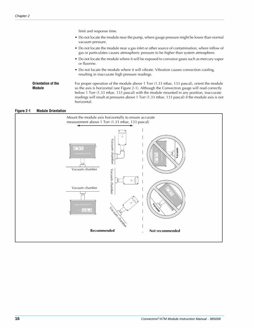
Orientation of the Module
For proper operation of the module above 1 Torr (1.33 mbar, 133 pascal), orient the module so the axis is horizontal (see Figure 2-1). Although the Convectron gauge will read correctly below 1 Torr (1.33 mbar, 133 pascal) with the module mounted in any position, inaccurate readings will result at pressures above 1 Torr (1.33 mbar, 133 pascal) if the module axis is not horizontal.
Figure 2-1 Module Orientation
Vacuum chamber
Vacuum chamber
Vacuum
chamber
Vacuum
chamber
Vacuum cham
ber
Vacuum
Vac
uum
Recommended Not recommended
Mount the module axis horizontally to ensure accurate measurement above 1 Torr (1.33 mbar, 133 pascal)
Installation
Convectron®ATM Module Instruction Manual - 385008 17
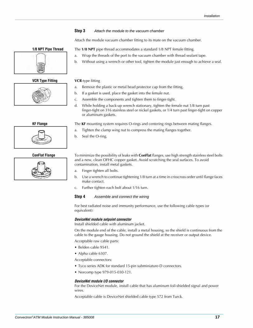
Step 3 Attach the module to the vacuum chamber
Attach the module vacuum chamber fitting to its mate on the vacuum chamber.
1/8 NPT Pipe Thread The 1/8 NPT pipe thread accommodates a standard 1/8 NPT female fitting.
a. Wrap the threads of the port to the vacuum chamber with thread sealant tape.
b. Without using a wrench or other tool, tighten the module just enough to achieve a seal.
VCR Type Fitting VCR-type fitting
a. Remove the plastic or metal bead protector cap from the fitting.
b. If a gasket is used, place the gasket into the female nut.
c. Assemble the components and tighten them to finger-tight.
d. While holding a back-up wrench stationary, tighten the female nut 1/8 turn past finger-tight on 316 stainless steel or nickel gaskets, or 1/4 turn past finger-tight on copper or aluminum gaskets.
KF Flange The KF mounting system requires O-rings and centering rings between mating flanges.
a. Tighten the clamp wing nut to compress the mating flanges together.
b. Seal the O-ring.
ConFlat Flange To minimize the possibility of leaks with ConFlat flanges, use high strength stainless steel bolts and a new, clean OFHC copper gasket. Avoid scratching the seal surfaces. To avoid contamination, install metal gaskets.
a. Finger tighten all bolts.
b. Use a wrench to continue tightening 1/8 turn at a time in crisscross order until flange faces make contact.
c. Further tighten each bolt about 1/16 turn.
Step 4 Assemble and connect the wiring
For best radiated noise and immunity performance, use the following cable types (or equivalent):
DeviceNet module setpoint connectorInstall shielded cable with aluminum jacket.
On the module end of the cable, install a metal housing, so the shield is continuous from the cable to the gauge housing. Do not ground the shield at the receiver or output device.
Acceptable raw cable parts:
• Belden cable 9541.
• Alpha cable 6307.
Acceptable connectors:
• Tyco series ADK for standard 15-pin subminiature-D connectors.
• Norcomp type 979-015-030-121.
DeviceNet module I/O connectorFor the DeviceNet module, install cable that has aluminum foil-shielded signal and power wires.
Acceptable cable is DeviceNet shielded cable type 572 from Turck.
Chapter 2
18 Convectron®ATM Module Instruction Manual - 385008
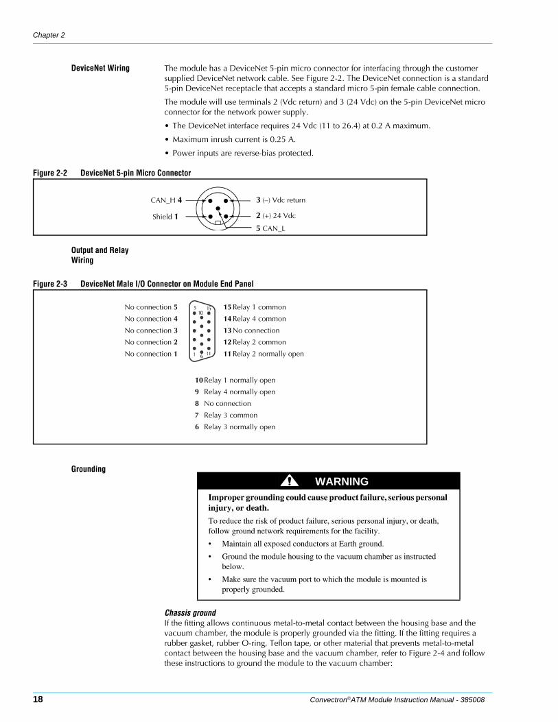
DeviceNet Wiring The module has a DeviceNet 5-pin micro connector for interfacing through the customer supplied DeviceNet network cable. See Figure 2-2. The DeviceNet connection is a standard 5-pin DeviceNet receptacle that accepts a standard micro 5-pin female cable connection.
The module will use terminals 2 (Vdc return) and 3 (24 Vdc) on the 5-pin DeviceNet micro connector for the network power supply.
• The DeviceNet interface requires 24 Vdc (11 to 26.4) at 0.2 A maximum.
• Maximum inrush current is 0.25 A.
• Power inputs are reverse-bias protected.
Figure 2-2 DeviceNet 5-pin Micro Connector
Output and Relay Wiring
Figure 2-3 DeviceNet Male I/O Connector on Module End Panel
Grounding
Chassis groundIf the fitting allows continuous metal-to-metal contact between the housing base and the vacuum chamber, the module is properly grounded via the fitting. If the fitting requires a rubber gasket, rubber O-ring, Teflon tape, or other material that prevents metal-to-metal contact between the housing base and the vacuum chamber, refer to Figure 2-4 and follow these instructions to ground the module to the vacuum chamber:
CAN_H 4
Shield 1
3 (–) Vdc return
2 (+) 24 Vdc
5 CAN_L
No connection 5
No connection 4
No connection 3
No connection 2
No connection 1
15 Relay 1 common
14 Relay 4 common
13 No connection
12 Relay 2 common
11 Relay 2 normally open
10Relay 1 normally open
9 Relay 4 normally open
8 No connection
7 Relay 3 common
6 Relay 3 normally open
WARNINGImproper grounding could cause product failure, serious personal injury, or death.
To reduce the risk of product failure, serious personal injury, or death, follow ground network requirements for the facility.
• Maintain all exposed conductors at Earth ground.
• Ground the module housing to the vacuum chamber as instructed below.
• Make sure the vacuum port to which the module is mounted is properly grounded.
Installation
Convectron®ATM Module Instruction Manual - 385008 19
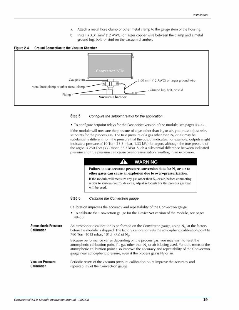
a. Attach a metal hose clamp or other metal clamp to the gauge stem of the housing.
b. Install a 3.31 mm2 (12 AWG) or larger copper wire between the clamp and a metal ground lug, bolt, or stud on the vacuum chamber.
Figure 2-4 Ground Connection to the Vacuum Chamber
Step 5 Configure the setpoint relays for the application
• To configure setpoint relays for the DeviceNet version of the module, see pages 43–47.
If the module will measure the pressure of a gas other than N2 or air, you must adjust relay setpoints for the process gas. The true pressure of a gas other than N2 or air may be substantially different from the pressure that the output indicates. For example, outputs might indicate a pressure of 10 Torr (13.3 mbar, 1.33 kPa) for argon, although the true pressure of the argon is 250 Torr (333 mbar, 33.3 kPa). Such a substantial difference between indicated pressure and true pressure can cause over-pressurization resulting in an explosion.
Step 6 Calibrate the Convectron gauge
Calibration improves the accuracy and repeatability of the Convectron gauge.
• To calibrate the Convectron gauge for the DeviceNet version of the module, see pages 49–50.
Atmospheric Pressure Calibration
An atmospheric calibration is performed on the Convectron gauge, using N2, at the factory before the module is shipped. The factory calibration sets the atmospheric calibration point to 760 Torr (1013 mbar, 101.3 kPa) of N2.
Because performance varies depending on the process gas, you may wish to reset the atmospheric calibration point if a gas other than N2 or air is being used. Periodic resets of the atmospheric calibration point also improve the accuracy and repeatability of the Convectron gauge near atmospheric pressure, even if the process gas is N2 or air.
Vacuum Pressure Calibration
Periodic resets of the vacuum pressure calibration point improve the accuracy and repeatability of the Convectron gauge.
Metal hose clamp or other metal clamp
3.00 mm2 (12 AWG) or larger ground wire
FittingVacuum Chamber
Ground lug, bolt, or stud
Gauge stem
WARNINGFailure to use accurate pressure conversion data for N2 or air to other gases can cause an explosion due to over−pressurization.
If the module will measure any gas other than N2 or air, before connecting relays to system control devices, adjust setpoints for the process gas that will be used.
Chapter 2
20 Convectron®ATM Module Instruction Manual - 385008
2.3 Eliminating Radio Frequency Interference
The module was tested and found to comply with U.S. Federal Communications Commission (FCC) limits for a Class A digital device, pursuant to Part 15 of the FCC rules. These limits provide reasonable protection against harmful interference when the module operates in a commercial environment.
The DeviceNet version of the module can radiate radio frequency energy and, if not installed and used in accordance with the instructions in this manual, may cause harmful interference to radio and television communications. However, there is no guarantee that interference will not occur in a particular installation. If operating the module in a residential area causes interference, the customer will be required to eliminate the interference at the customer’s own expense. If the module causes interference to radio or television reception, which can be determined by turning the module OFF and ON, use one of the following methods to eliminate the interference:
• Reorient or relocate the receiving antenna.
• Increase the separation between the module and the receiver.
• Connect the module into an outlet on a circuit that is not the circuit to which the receiver is connected.
• Consult an experienced radio or television technician for help.
Convectron®ATM Module Instruction Manual - 385008 21
Chapter 3 Operation Overview
3.1 Preparing for Pressure Measurement
The steps in this chapter assume:•The 275 Mini-Convectron was properly set up and installed per the instructions in Chapter
2.
•The gas in your vacuum system is air or N2. If you are using other gases you must follow the instructions in Section 3.4.
•You are reasonably familiar with the general theory of operation of thermal conductivity gauges.
It is recommended that you consult a good textbook if you are unfamiliar with vacuum technology or if you require more information on the general theory behind operating a thermal conductivity gauge. The following books are useful reference volumes.
•Dushman, S., Lafferty, J. M., Scientific Foundations Of Vacuum Technique, John Wiley & Sons, Inc., Second Edition, New York, 1962.
•Redhead, P. A., et al., Ultrahigh Vacuum, Chapman and Hall, London, 1968.
•O'Hanlon, J. F., A User’s Guide To Vacuum Technology, John Wiley & Sons, New York, 1980.
3.2 Gas Type The Convectron gauge in the Mini-Convectron Module is calibrated for N2 unless otherwise labeled for custom applications.
3.3 Preparing For Convectron Gauge Operation
Install pressure limiting devices calibrated to a level that the vacuum system can safely withstand. In addition, install pressure relief valves or rupture disks that will release pressure at a level considerably below the maximum safe pressure level of the system.
Suppliers of pressure relief valves and pressure relief disks can be located via an internet search. Confirm that these safety devices are properly installed before operating the Series 385 Mini-Convectron Module. In addition, check that (1) the proper gas cylinders are installed, (2) gas cylinder valve positions are correct on manual systems, and (3) the automation settings are correct on automated gas delivery systems.
NOTE: Vacuum gauges with compression fittings may be forcefully ejected if the vacuum system is pressurized.
3.4 Understanding Convectron Gauge Pressure Measurement
Convectron Gauges are Pirani type thermal conductivity gauges. These gauges measure the heat loss from a heated sensor wire maintained at constant temperature. The controller converts this measurement into gas pressure readings. For gases other than nitrogen or air the heat loss varies at any given true pressure and can result in inaccurate pressure readings.
WARNINGIf used improperly, Convectron Gauges can supply misleading pressure indications that can result in dangerous overpressure conditions within the system. For use with gases other than air, or N2 consult the gas type correction charts in Section 3.6.
CAUTIONOperating the module above 1000 Torr (1333 mbar, 133 kPa) true pressure could cause pressure measurement error or product failure.To avoid measurement error or product failure due to over−pressurization, install pressure relief valves or rupture disks in the system if pressure exceeds 1000 Torr (1333 mbar, 133 kPa).

Chapter 3
22 Convectron®ATM Module Instruction Manual - 385008
Gases Other Than Nitrogen or Air
NOTE: The information in this section applies only when the Convectron Gauge is calibrated for N2 and the Convectron Gauge is mounted with its axis horizontal.
It is important to understand that the pressure indicated by a Convectron Gauge depends on the type of gas, the orientation of the gauge axis, and on the gas density in the gauge. Convectron Gauges are normally factory calibrated for N2 (air has approximately the same calibration). With proper precautions, the Convectron Gauge may be used for pressure measurement of certain other gases.
At pressures below a few Torr, there is no danger in measuring pressure of gases other than N2 and air, merely inaccurate readings. A danger arises if the N2 calibration is used without correction to measure higher pressure levels of some other gases. For example, N2 at 24 Torr causes the same heat loss from the Convectron sensor as argon will at atmospheric pressure. If the pressure indication of the Convectron Gauge is not properly corrected for argon, an operator attempting to fill a vacuum system with 1/2 atmosphere of argon would observe a pressure reading of only 12 Torr when the actual pressure had risen to the desired 380 Torr. Continuing to fill the system with argon to 760 Torr would result in a 24 Torr pressure reading.
Depending on the pressure of the argon gas source, the chamber could be dangerously pressurized while the display continued to read about 30 Torr of N2 equivalent pressure.
NOTE: This type of danger is not unique to the Convectron Gauge and likely exists with other thermal conductivity gauges using convection to extend the range to high pressures.
To measure the pressure of gases other than air, or N2 with a Convectron Gauge calibrated for N2, you must use the conversion curves listed specifically for Convectron Gauges to translate between indicated pressure and true pressure. Do not use other data. Never use the conversion curves designed for Convectron Gauges to translate pressure readings for gauges made by other manufacturers. Their geometry is very likely different and dangerously high pressures may be produced even at relatively low pressure indications.
NOTE: You must ensure that the atmosphere adjustments for the Convectron Gauge are correctly set.
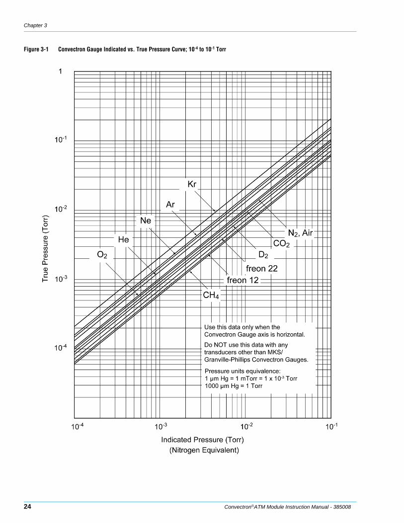
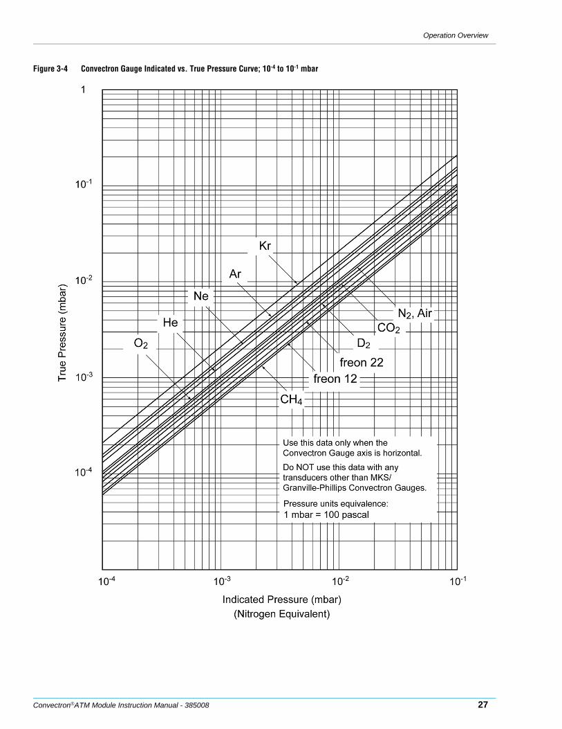
Figures 3-1 through 3-6 show the true pressure vs. the indicated pressure for eleven commonly used gases. Table 3-1 will help to locate the proper graph.
1 mbar = 100 Pa = 1.33 Torr, so the charts can be used for pascal and mbar units.
WARNINGUsing the N2 calibration to pressurize a vacuum system above about 1 Torr with certain other gases can cause dangerously high pressures which may cause explosion of the system. See Section 3.6 before using with other gases.
Table 3-1 Pressure vs. Indicated N2 Pressure Curve.
Fig. No. Pressure Range and Units Gases
3-1 10-4 to 10-1 Torr All
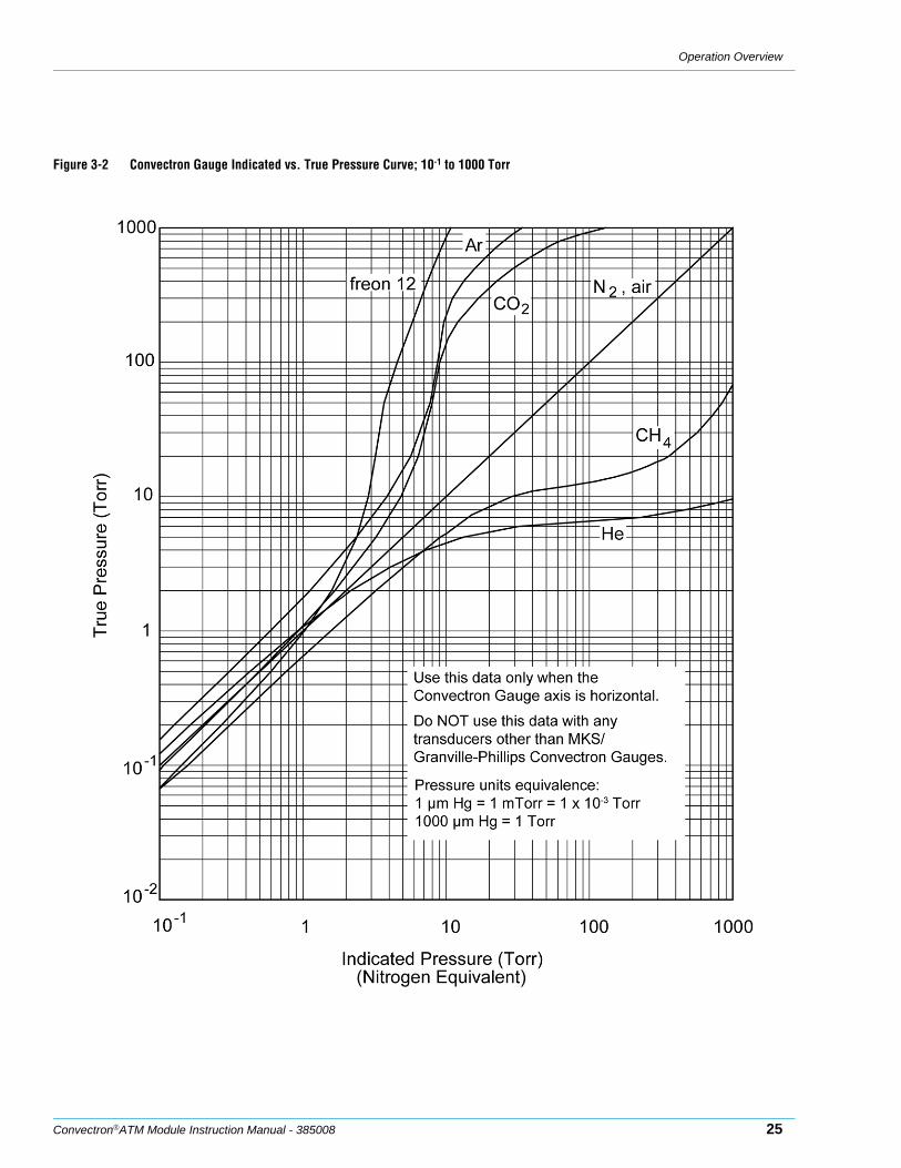
3-2 10-1 to 1000 Torr Ar, C02, CH4, Freon 12, He
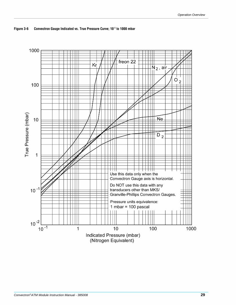
3-3 10-1 to 1000 Torr D2, Freon 22, Kr, Ne, 02
3-4 10-4 to 10-1 mbar All
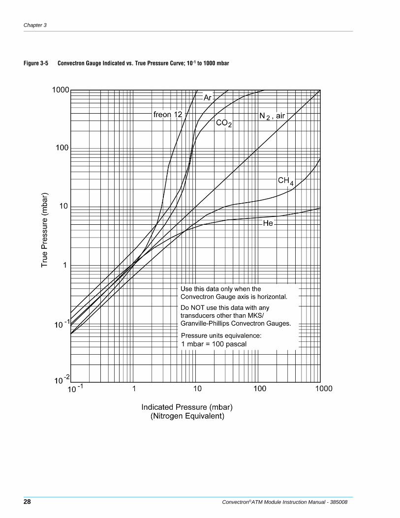
3-5 10-1 to 1000 mbar Ar, C02, CH4, Freon 12, He
3-6 10-1 to 1000 mbar D2, Freon 22, Kr, Ne, 02
Operation Overview
Convectron®ATM Module Instruction Manual - 385008 23
A useful interpretation of these curves is, for example, that at a true pressure of 2 x 10⁻² Torr for CH4 the heat loss from the sensor is the same as at a true pressure of 3 x 10⁻² for N2 (see Figure 3-1). The curves at higher pressure vary widely from gas to gas because thermal losses at higher pressures are greatly different for different gases.
If you must measure the pressure of gases other than N2 or air, use Figure 3-1 through Figure 3-6 to determine the maximum safe indicated pressure for the other gas as explained in the examples that follow.
Examples The following graphs enable you to determine the indicated N2 or air pressure that corresponds to a specific true pressure of 10 other commonly used process gases. Find the point at which the horizontal line representing true pressure intercepts the vertical line representing indicated N2 (nitrogen equivalent) pressure. If the gas being used is not included among those listed, or for a gas mixture, generate a calibration curve using a gas-independent transfer standard such as a capacitance manometer.
Example 1 – Maximum safe indicated pressure.Assume a given vacuum system will withstand an internal pressure of 2000 Torr or 38.7 psia. For safety, you wish to limit the maximum internal pressure to 760 Torr during the backfilling process. Assume you wish to measure the pressure of Freon 22. On Figure 3-3, locate 760 Torr on the left hand scale, travel to the right to the intersection with the Freon 22 curve, and then down to an indicated pressure of 11 Torr (N2 equivalent). In this hypothetical situation, the maximum safe indicated pressure for Freon 22 is 11 Torr.
For the sake of safety, it is prudent to place a warning label on the instrument face stating “DO NOT EXCEED 11 TORR FOR FREON 22" for this example.
Example 2 – Indicated to true pressure conversion.Assume you wish to determine the true pressure of helium in a system when the Convectron is indicating 10 Torr. On Figure 3-2, follow the vertical graph line up from the 10 Torr (N2 equivalent) indicated pressure to the Helium curve and then move horizontally to the left to reveal a true pressure of 4.5 Torr. Thus 4.5 Torr Helium pressure produces an indication of 10 Torr (N2 equivalent).
Example 3 – True to indicated pressure conversion.Assume you wish to set a process control setpoint at a true pressure of 20 Torr of C02. On Figure 3-2, locate 20 Torr on the true pressure scale, travel horizontally to the right to the C02 curve and then down to an indicated pressure of 6.4 Torr (N2 equivalent). The correct process control setting for 20 Torr of C02 is 6.4 Torr (N2 equivalent).
Example 4 – True to indicated pressure conversion.Assume you wish to obtain a helium pressure of 100 Torr in the system. On Figure 3-2, locate 100 Torr on the left hand scale, travel horizontally to the right to attempt to intersect the He curve. Because the intersection is off scale, it is apparent that this true pressure measurement requirement for helium exceeds the capability of the instrument.
CAUTIONFor gases other than those listed, the user must provide accurate conversion data for safe operation. The Convectron Gauge is not intended for use above approximately 1000 Torr true pressure.
Chapter 3
24 Convectron®ATM Module Instruction Manual - 385008
Figure 3-1 Convectron Gauge Indicated vs. True Pressure Curve; 10-4 to 10-1 Torr
Operation Overview
Convectron®ATM Module Instruction Manual - 385008 25
Figure 3-2 Convectron Gauge Indicated vs. True Pressure Curve; 10-1 to 1000 Torr

Chapter 3
26 Convectron®ATM Module Instruction Manual - 385008
Figure 3-3 Convectron Gauge Indicated vs. True Pressure Curve; 10-1 to 1000 Torr
Operation Overview
Convectron®ATM Module Instruction Manual - 385008 27
Figure 3-4 Convectron Gauge Indicated vs. True Pressure Curve; 10-4 to 10-1 mbar
Chapter 3
28 Convectron®ATM Module Instruction Manual - 385008
Figure 3-5 Convectron Gauge Indicated vs. True Pressure Curve; 10-1 to 1000 mbar
Operation Overview
Convectron®ATM Module Instruction Manual - 385008 29
Figure 3-6 Convectron Gauge Indicated vs. True Pressure Curve; 10-1 to 1000 mbar
Chapter 3
30 Convectron®ATM Module Instruction Manual - 385008
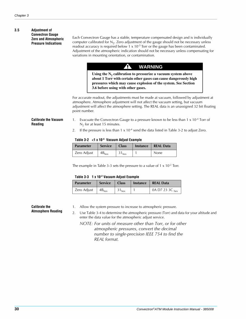
3.5 Adjustment of Convectron Gauge Zero and Atmospheric Pressure Indications
Each Convectron Gauge has a stable, temperature compensated design and is individually computer calibrated for N2. Zero adjustment of the gauge should not be necessary unless readout accuracy is required below 1 x 10⁻³ Torr or the gauge has been contaminated. Adjustment of the atmospheric indication should not be necessary unless compensating for variations in mounting orientation, or contamination.
For accurate readout, the adjustments must be made at vacuum, followed by adjustment at atmosphere. Atmosphere adjustment will not affect the vacuum setting, but vacuum adjustment will affect the atmosphere setting. The REAL data is an unassigned 32 bit floating point number.
Calibrate the Vacuum Reading
1. Evacuate the Convectron Gauge to a pressure known to be less than 1 x 10⁻⁴ Torr of N2 for at least 15 minutes.
2. If the pressure is less than 1 x 10⁻⁴ send the data listed in Table 3-2 to adjust Zero.
The example in Table 3-3 sets the pressure to a value of 1 x 10⁻² Torr.
Calibrate the Atmosphere Reading
1. Allow the system pressure to increase to atmospheric pressure.
2. Use Table 3-4 to determine the atmospheric pressure (Torr) and data for your altitude and enter the data value for the atmospheric adjust service.
NOTE: For units of measure other than Torr, or for other atmospheric pressures, convert the decimal number to single-precision IEEE 754 to find the REAL format.
WARNINGUsing the N2 calibration to pressurize a vacuum system above about 1 Torr with certain other gases can cause dangerously high pressures which may cause explosion of the system. See Section 3.6 before using with other gases.
Table 3-2 <1 x 10⁻⁴ Vacuum Adjust Example
Parameter Service Class Instance REAL Data
Zero Adjust 4Bhex 31hex 1 None
Table 3-3 1 x 10⁻² Vacuum Adjust Example
Parameter Service Class Instance REAL Data
Zero Adjust 4Bhex 31hex 1 0A D7 23 3C hex
Operation Overview
Convectron®ATM Module Instruction Manual - 385008 31
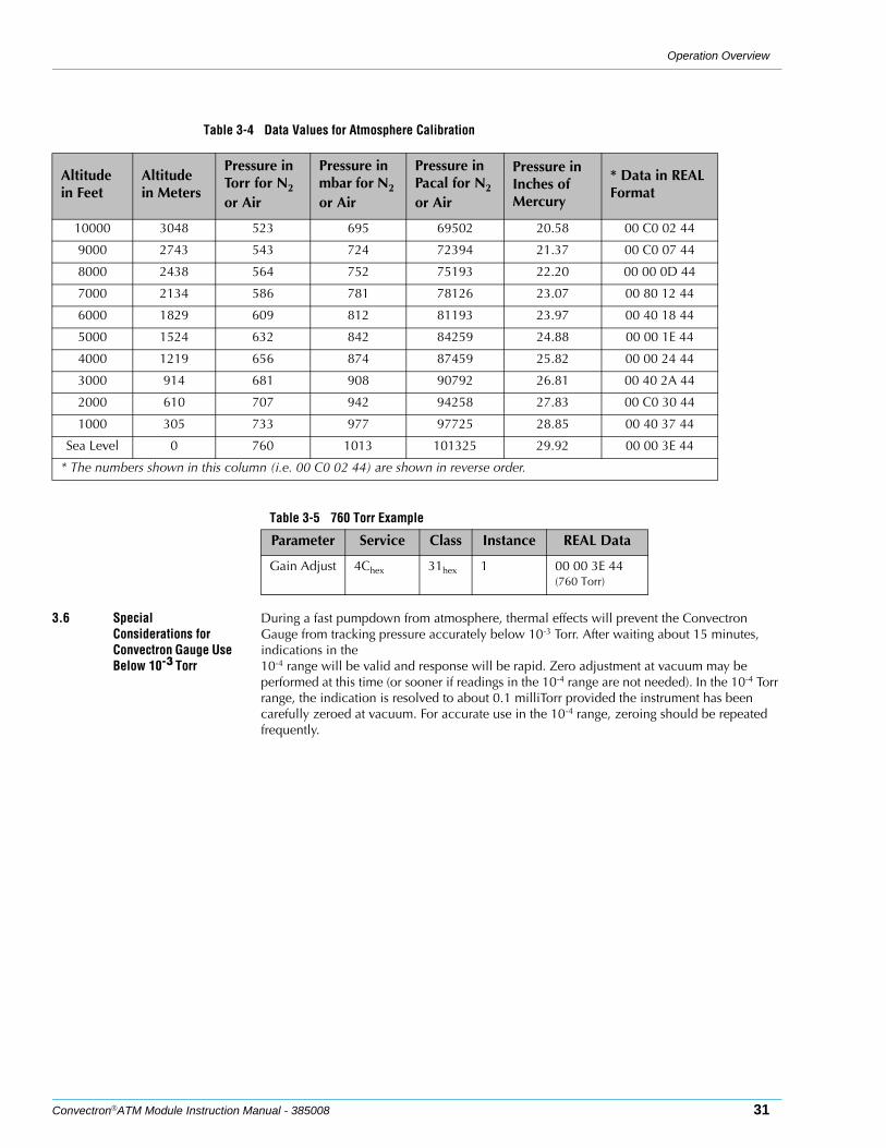
3.6 Special Considerations for Convectron Gauge Use Below 10-3 Torr
During a fast pumpdown from atmosphere, thermal effects will prevent the Convectron Gauge from tracking pressure accurately below 10-3 Torr. After waiting about 15 minutes, indications in the 10-4 range will be valid and response will be rapid. Zero adjustment at vacuum may be performed at this time (or sooner if readings in the 10-4 range are not needed). In the 10-4 Torr range, the indication is resolved to about 0.1 milliTorr provided the instrument has been carefully zeroed at vacuum. For accurate use in the 10-4 range, zeroing should be repeated frequently.
Table 3-4 Data Values for Atmosphere Calibration
Altitude in Feet
Altitude in Meters
Pressure in Torr for N2 or Air
Pressure in mbar for N2 or Air
Pressure in Pacal for N2 or Air
Pressure in Inches of Mercury
* Data in REAL Format
10000 3048 523 695 69502 20.58 00 C0 02 44
9000 2743 543 724 72394 21.37 00 C0 07 44
8000 2438 564 752 75193 22.20 00 00 0D 44
7000 2134 586 781 78126 23.07 00 80 12 44
6000 1829 609 812 81193 23.97 00 40 18 44
5000 1524 632 842 84259 24.88 00 00 1E 44
4000 1219 656 874 87459 25.82 00 00 24 44
3000 914 681 908 90792 26.81 00 40 2A 44
2000 610 707 942 94258 27.83 00 C0 30 44
1000 305 733 977 97725 28.85 00 40 37 44
Sea Level 0 760 1013 101325 29.92 00 00 3E 44
* The numbers shown in this column (i.e. 00 C0 02 44) are shown in reverse order.
Table 3-5 760 Torr Example
Parameter Service Class Instance REAL Data
Gain Adjust 4Chex 31hex 1 00 00 3E 44(760 Torr)

Chapter 3
32 Convectron®ATM Module Instruction Manual - 385008
NOTES
Convectron®ATM Module Instruction Manual - 385008 33
Chapter 4 DeviceNet Operation
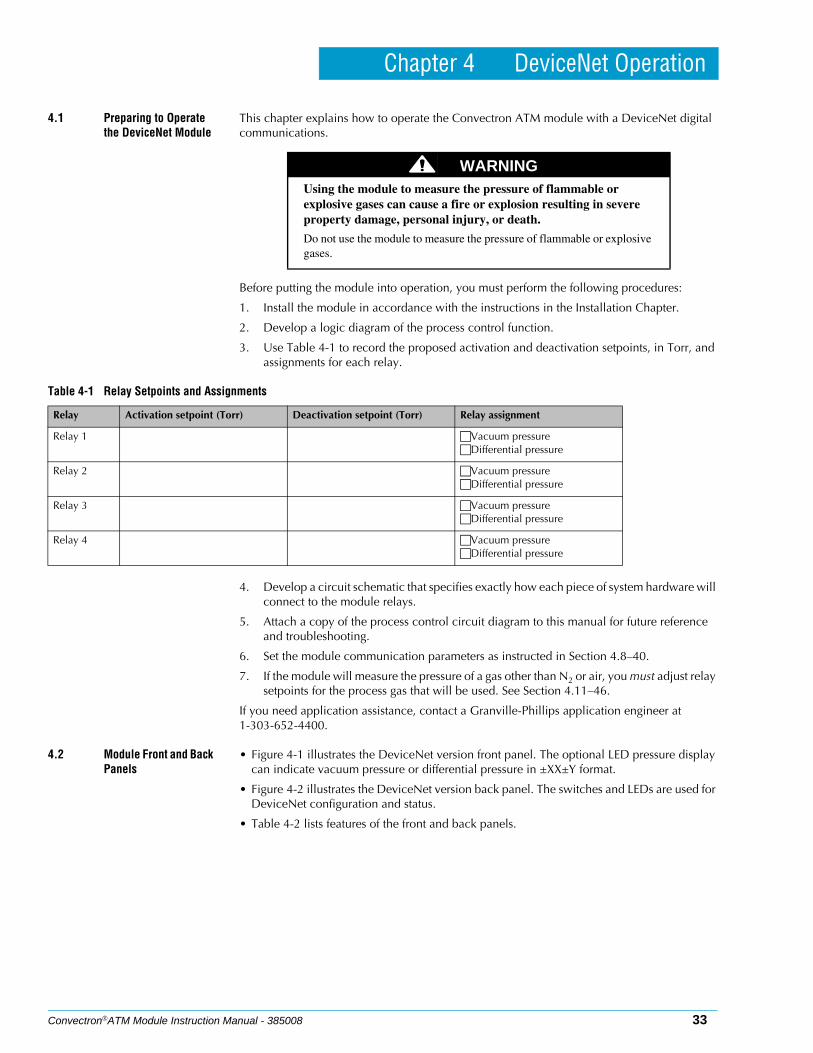
4.1 Preparing to Operate the DeviceNet Module
This chapter explains how to operate the Convectron ATM module with a DeviceNet digital communications.
Before putting the module into operation, you must perform the following procedures:
1. Install the module in accordance with the instructions in the Installation Chapter.
2. Develop a logic diagram of the process control function.
3. Use Table 4-1 to record the proposed activation and deactivation setpoints, in Torr, and assignments for each relay.
4. Develop a circuit schematic that specifies exactly how each piece of system hardware will connect to the module relays.
5. Attach a copy of the process control circuit diagram to this manual for future reference and troubleshooting.
6. Set the module communication parameters as instructed in Section 4.8–40.
7. If the module will measure the pressure of a gas other than N2 or air, you must adjust relay setpoints for the process gas that will be used. See Section 4.11–46.
If you need application assistance, contact a Granville-Phillips application engineer at 1-303-652-4400.
4.2 Module Front and Back Panels
• Figure 4-1 illustrates the DeviceNet version front panel. The optional LED pressure display can indicate vacuum pressure or differential pressure in ±XX±Y format.
• Figure 4-2 illustrates the DeviceNet version back panel. The switches and LEDs are used for DeviceNet configuration and status.
• Table 4-2 lists features of the front and back panels.
WARNINGUsing the module to measure the pressure of flammable or explosive gases can cause a fire or explosion resulting in severe property damage, personal injury, or death.
Do not use the module to measure the pressure of flammable or explosive gases.
Table 4-1 Relay Setpoints and Assignments
Relay Activation setpoint (Torr) Deactivation setpoint (Torr) Relay assignment
Relay 1 Vacuum pressureDifferential pressure
Relay 2 Vacuum pressureDifferential pressure
Relay 3 Vacuum pressureDifferential pressure
Relay 4 Vacuum pressureDifferential pressure
Chapter 4
34 Convectron®ATM Module Instruction Manual - 385008
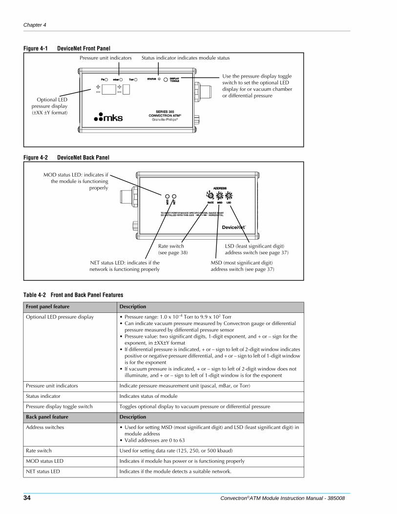
Figure 4-1 DeviceNet Front Panel
Figure 4-2 DeviceNet Back Panel
Pressure unit indicators
Optional LEDpressure display(±XX ±Y format)
Status indicator indicates module status
Use the pressure display toggle switch to set the optional LED display for or vacuum chamber or differential pressure
MSD (most significant digit) address switch (see page 37)
LSD (least significant digit) address switch (see page 37)
Rate switch (see page 38)
NET status LED: indicates if thenetwork is functioning properly
MOD status LED: indicates ifthe module is functioning
properly
Table 4-2 Front and Back Panel Features
Front panel feature Description
Optional LED pressure display • Pressure range: 1.0 x 10⁻⁴ Torr to 9.9 x 10² Torr• Can indicate vacuum pressure measured by Convectron gauge or differential
pressure measured by differential pressure sensor• Pressure value: two significant digits, 1-digit exponent, and + or – sign for the
exponent, in ±XX±Y format• If differential pressure is indicated, + or – sign to left of 2-digit window indicates
positive or negative pressure differential, and + or – sign to left of 1-digit window is for the exponent
• If vacuum pressure is indicated, + or – sign to left of 2-digit window does not illuminate, and + or – sign to left of 1-digit window is for the exponent
Pressure unit indicators Indicate pressure measurement unit (pascal, mBar, or Torr)
Status indicator Indicates status of module
Pressure display toggle switch Toggles optional display to vacuum pressure or differential pressure
Back panel feature Description
Address switches • Used for setting MSD (most significant digit) and LSD (least significant digit) in module address
• Valid addresses are 0 to 63
Rate switch Used for setting data rate (125, 250, or 500 kbaud)
MOD status LED Indicates if module has power or is functioning properly
NET status LED Indicates if the module detects a suitable network.
DeviceNet Operation
Convectron®ATM Module Instruction Manual - 385008 35
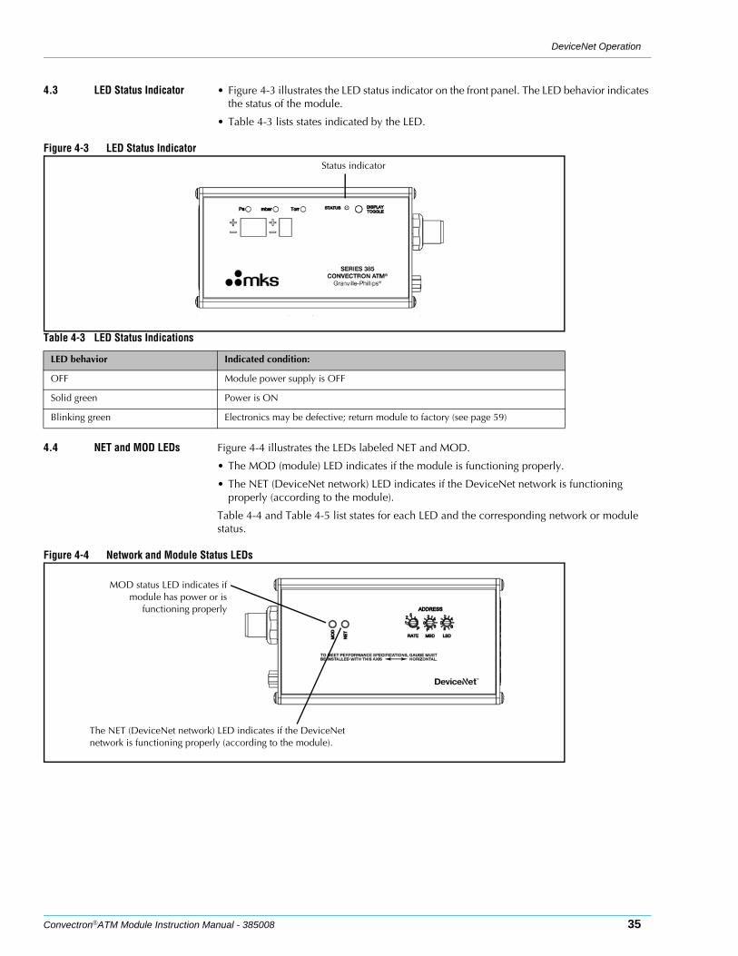
4.3 LED Status Indicator • Figure 4-3 illustrates the LED status indicator on the front panel. The LED behavior indicates the status of the module.
• Table 4-3 lists states indicated by the LED.
Figure 4-3 LED Status Indicator
4.4 NET and MOD LEDs Figure 4-4 illustrates the LEDs labeled NET and MOD.
• The MOD (module) LED indicates if the module is functioning properly.
• The NET (DeviceNet network) LED indicates if the DeviceNet network is functioning properly (according to the module).
Table 4-4 and Table 4-5 list states for each LED and the corresponding network or module status.
Figure 4-4 Network and Module Status LEDs
Status indicator
Table 4-3 LED Status Indications
LED behavior Indicated condition:
OFF Module power supply is OFF
Solid green Power is ON
Blinking green Electronics may be defective; return module to factory (see page 59)
The NET (DeviceNet network) LED indicates if the DeviceNet network is functioning properly (according to the module).
MOD status LED indicates ifmodule has power or is
functioning properly
Chapter 4
36 Convectron®ATM Module Instruction Manual - 385008
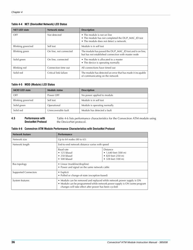
4.5 Performance with DeviceNet Protocol
Table 4-6 lists performance characteristics for the Convectron ATM module using the DeviceNet protocol.
Table 4-4 NET (DeviceNet Network) LED Status
NET LED state Network status Description
OFF Not detected • The module is not on line• The module has not completed the DUP_MAC_ID test• The module does not detect a network.
Blinking green/red Self test Module is in self test
Blinking green On line, not connected The module has passed the DUP_MAC_ID test and is on line, but has not established connection with master node
Solid green On line, connected • The module is allocated to a master• The device is operating normally
Blinking red Connection time out All connections have timed out
Solid red Critical link failure The module has detected an error that has made it incapable of communicating on the network
Table 4-5 MOD (Module) LED Status
MOD LED state Module status Description
OFF Power OFF No power applied to module
Blinking green/red Self test Module is in self test
Solid green Operational Module is operating normally
Solid red Unrecoverable fault Module has detected a fault
Table 4-6 Convectron ATM Module Performance Characteristics with DeviceNet Protocol
Network feature Performance
Network size Up to 64 nodes (00 to 63)
Network length End-to-end network distance varies with speed
Baud rate• 125 kbaud• 250 kbaud• 500 kbaud
Distance• 1,640 feet (500 m)• 820 feet (250 m)• 328 feet (100 m)
Bus topology • Linear (trunkline/dropline)• Power and signal on the same network cable
Supported Connectors • Explicit• Polled or change-of-state (exception-based)
System features • Module can be removed and replaced while network power supply is ON• Module can be programmed while network power supply is ON (some program
changes will take effect after power has been cycled)
DeviceNet Operation
Convectron®ATM Module Instruction Manual - 385008 37
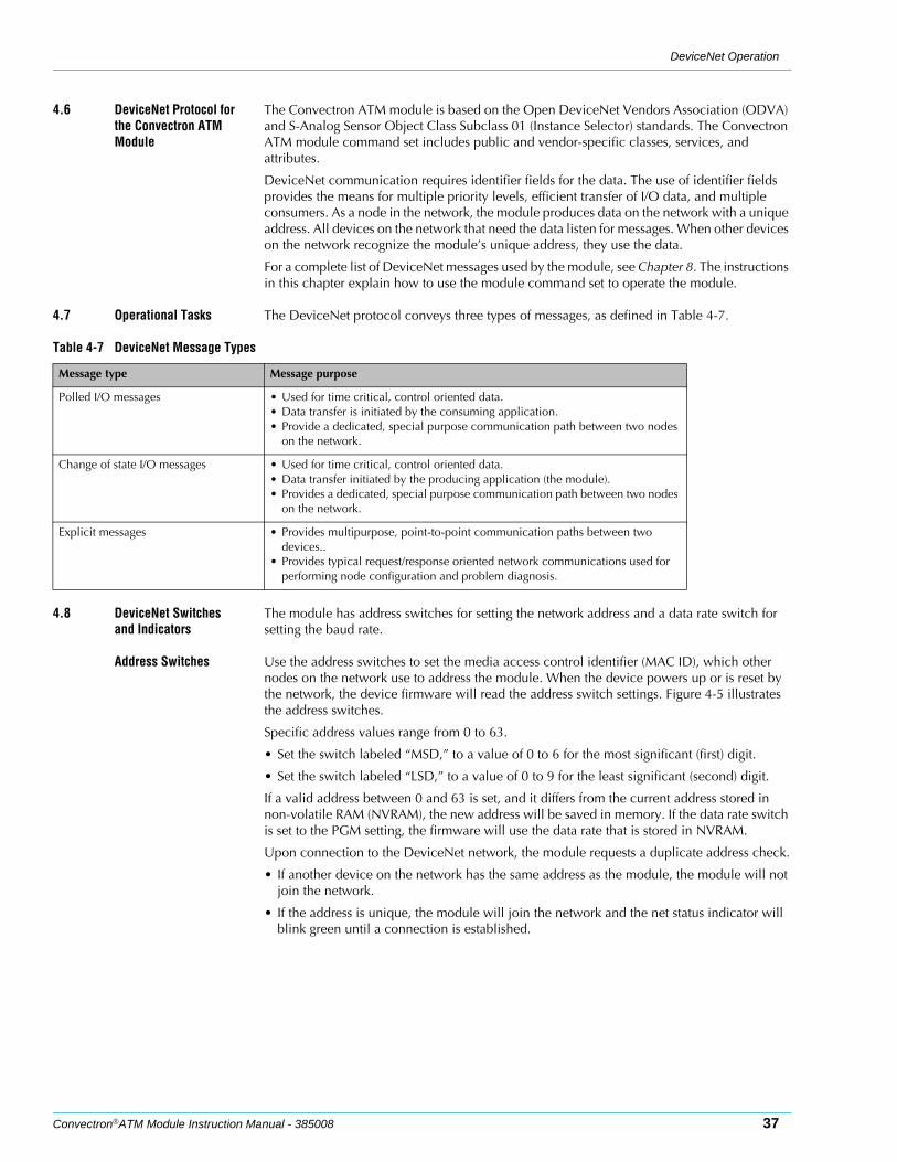
4.6 DeviceNet Protocol for the Convectron ATM Module
The Convectron ATM module is based on the Open DeviceNet Vendors Association (ODVA) and S-Analog Sensor Object Class Subclass 01 (Instance Selector) standards. The Convectron ATM module command set includes public and vendor-specific classes, services, and attributes.
DeviceNet communication requires identifier fields for the data. The use of identifier fields provides the means for multiple priority levels, efficient transfer of I/O data, and multiple consumers. As a node in the network, the module produces data on the network with a unique address. All devices on the network that need the data listen for messages. When other devices on the network recognize the module’s unique address, they use the data.
For a complete list of DeviceNet messages used by the module, see Chapter 8. The instructions in this chapter explain how to use the module command set to operate the module.
4.7 Operational Tasks The DeviceNet protocol conveys three types of messages, as defined in Table 4-7.
4.8 DeviceNet Switches and Indicators
The module has address switches for setting the network address and a data rate switch for setting the baud rate.
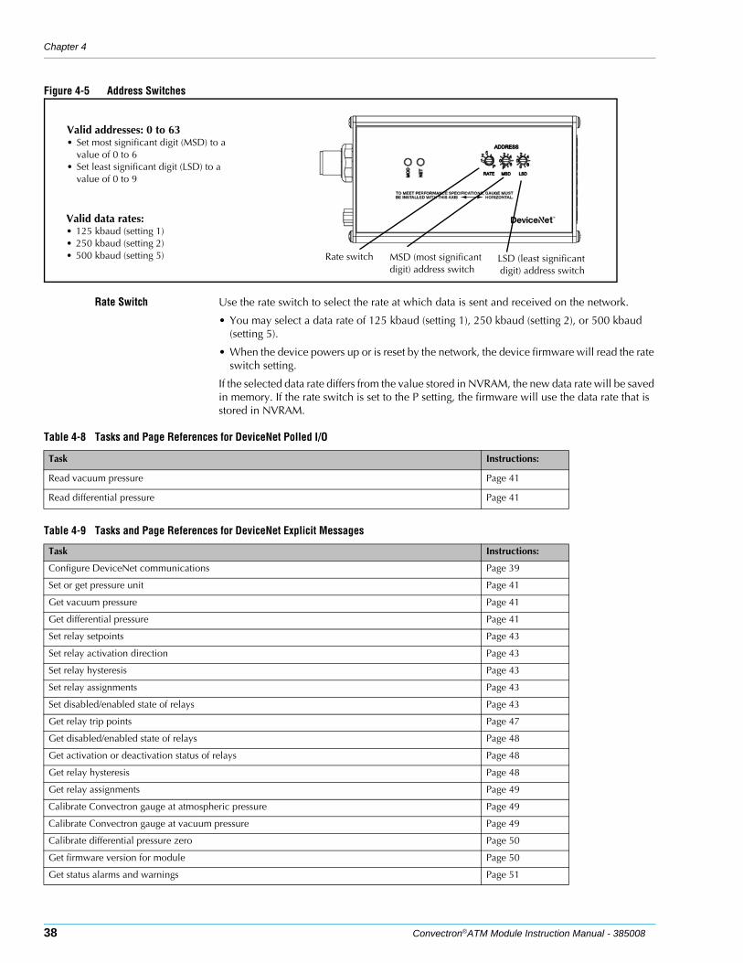
Address Switches Use the address switches to set the media access control identifier (MAC ID), which other nodes on the network use to address the module. When the device powers up or is reset by the network, the device firmware will read the address switch settings. Figure 4-5 illustrates the address switches.
Specific address values range from 0 to 63.
• Set the switch labeled “MSD,” to a value of 0 to 6 for the most significant (first) digit.
• Set the switch labeled “LSD,” to a value of 0 to 9 for the least significant (second) digit.
If a valid address between 0 and 63 is set, and it differs from the current address stored in non-volatile RAM (NVRAM), the new address will be saved in memory. If the data rate switch is set to the PGM setting, the firmware will use the data rate that is stored in NVRAM.
Upon connection to the DeviceNet network, the module requests a duplicate address check.
• If another device on the network has the same address as the module, the module will not join the network.
• If the address is unique, the module will join the network and the net status indicator will blink green until a connection is established.
Table 4-7 DeviceNet Message Types
Message type Message purpose
Polled I/O messages • Used for time critical, control oriented data.• Data transfer is initiated by the consuming application.• Provide a dedicated, special purpose communication path between two nodes
on the network.
Change of state I/O messages • Used for time critical, control oriented data.• Data transfer initiated by the producing application (the module).• Provides a dedicated, special purpose communication path between two nodes
on the network.
Explicit messages • Provides multipurpose, point-to-point communication paths between two devices..
• Provides typical request/response oriented network communications used for performing node configuration and problem diagnosis.
Chapter 4
38 Convectron®ATM Module Instruction Manual - 385008
Figure 4-5 Address Switches
Rate Switch Use the rate switch to select the rate at which data is sent and received on the network.
• You may select a data rate of 125 kbaud (setting 1), 250 kbaud (setting 2), or 500 kbaud (setting 5).
• When the device powers up or is reset by the network, the device firmware will read the rate switch setting.
If the selected data rate differs from the value stored in NVRAM, the new data rate will be saved in memory. If the rate switch is set to the P setting, the firmware will use the data rate that is stored in NVRAM.
Valid addresses: 0 to 63• Set most significant digit (MSD) to a
value of 0 to 6• Set least significant digit (LSD) to a
value of 0 to 9
MSD (most significant digit) address switch
LSD (least significantdigit) address switch
Rate switch
Valid data rates:• 125 kbaud (setting 1)• 250 kbaud (setting 2)• 500 kbaud (setting 5)
Table 4-8 Tasks and Page References for DeviceNet Polled I/O
Task Instructions:
Read vacuum pressure Page 41
Read differential pressure Page 41
Table 4-9 Tasks and Page References for DeviceNet Explicit Messages
Task Instructions:
Configure DeviceNet communications Page 39
Set or get pressure unit Page 41
Get vacuum pressure Page 41
Get differential pressure Page 41
Set relay setpoints Page 43
Set relay activation direction Page 43
Set relay hysteresis Page 43
Set relay assignments Page 43
Set disabled/enabled state of relays Page 43
Get relay trip points Page 47
Get disabled/enabled state of relays Page 48
Get activation or deactivation status of relays Page 48
Get relay hysteresis Page 48
Get relay assignments Page 49
Calibrate Convectron gauge at atmospheric pressure Page 49
Calibrate Convectron gauge at vacuum pressure Page 49
Calibrate differential pressure zero Page 50
Get firmware version for module Page 50
Get status alarms and warnings Page 51
DeviceNet Operation
Convectron®ATM Module Instruction Manual - 385008 39
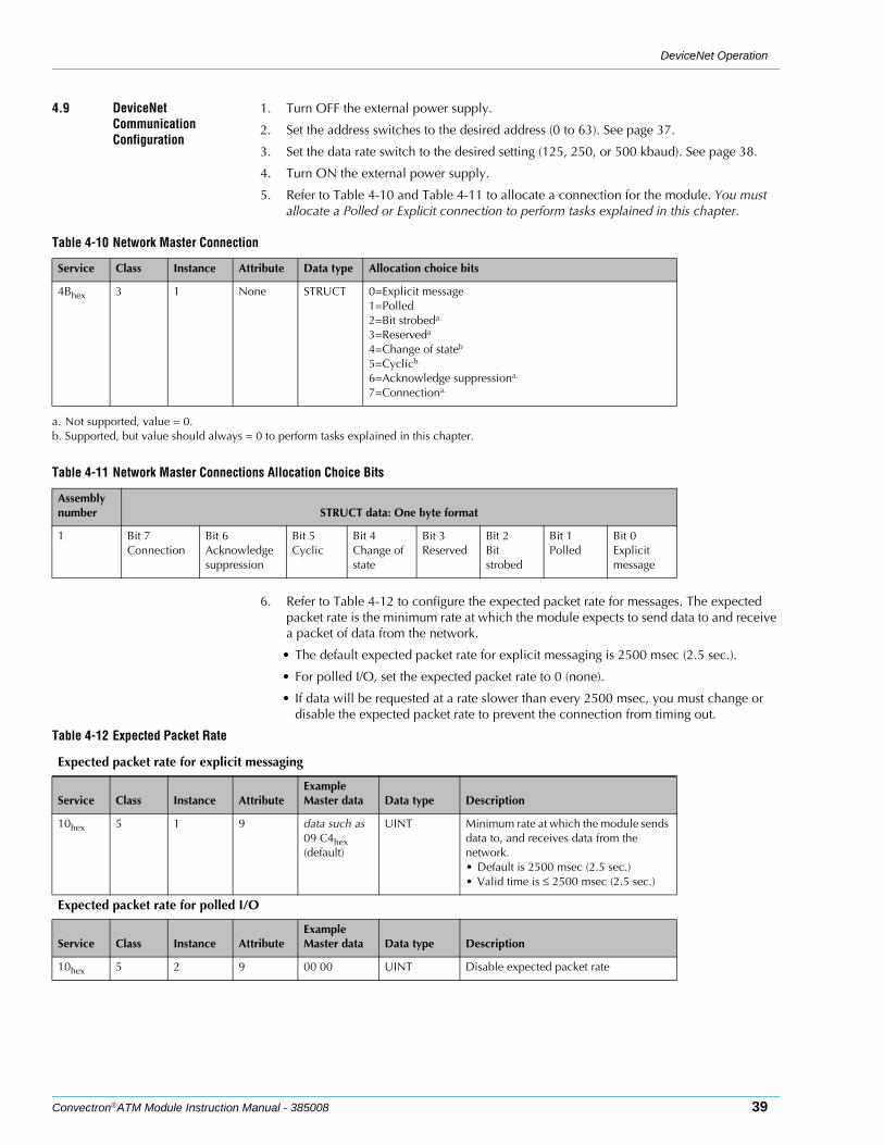
4.9 DeviceNet Communication Configuration
1. Turn OFF the external power supply.
2. Set the address switches to the desired address (0 to 63). See page 37.
3. Set the data rate switch to the desired setting (125, 250, or 500 kbaud). See page 38.
4. Turn ON the external power supply.
5. Refer to Table 4-10 and Table 4-11 to allocate a connection for the module. You must allocate a Polled or Explicit connection to perform tasks explained in this chapter.
6. Refer to Table 4-12 to configure the expected packet rate for messages. The expected packet rate is the minimum rate at which the module expects to send data to and receive a packet of data from the network.
• The default expected packet rate for explicit messaging is 2500 msec (2.5 sec.).
• For polled I/O, set the expected packet rate to 0 (none).
• If data will be requested at a rate slower than every 2500 msec, you must change or disable the expected packet rate to prevent the connection from timing out.
Table 4-10 Network Master Connection
Service Class Instance Attribute Data type Allocation choice bits
4Bhex 3 1 None STRUCT 0=Explicit message1=Polled2=Bit strobeda.
3=Reserveda
4=Change of stateb
5=Cyclicb.
6=Acknowledge suppressiona.
7=Connectiona.
a. Not supported, value = 0.b. Supported, but value should always = 0 to perform tasks explained in this chapter.
Table 4-11 Network Master Connections Allocation Choice Bits
Assembly number STRUCT data: One byte format
1 Bit 7Connection
Bit 6Acknowledge suppression
Bit 5Cyclic
Bit 4Change of state
Bit 3Reserved
Bit 2Bit strobed
Bit 1Polled
Bit 0Explicit message
Table 4-12 Expected Packet Rate
Expected packet rate for explicit messaging
Service Class Instance AttributeExample Master data Data type Description
10hex 5 1 9 data such as09 C4hex (default)
UINT Minimum rate at which the module sends data to, and receives data from the network.• Default is 2500 msec (2.5 sec.)• Valid time is ≤ 2500 msec (2.5 sec.)
Expected packet rate for polled I/O
Service Class Instance AttributeExample Master data Data type Description
10hex 5 2 9 00 00 UINT Disable expected packet rate
Chapter 4
40 Convectron®ATM Module Instruction Manual - 385008
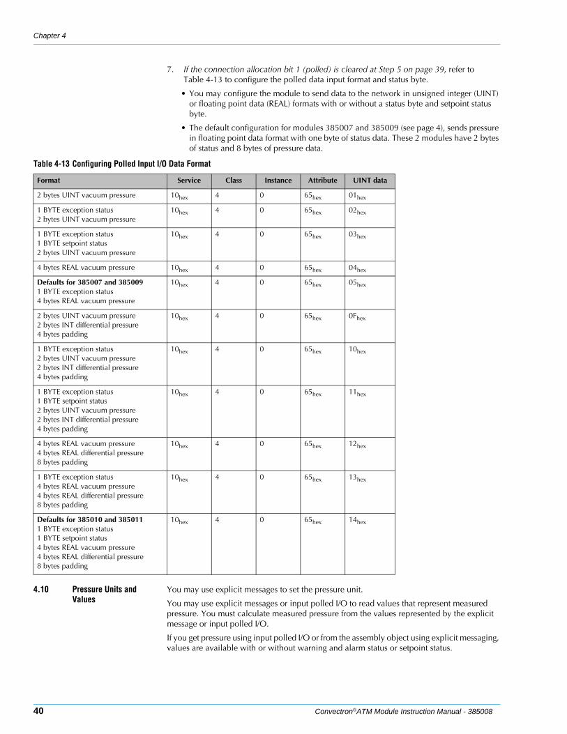
7. If the connection allocation bit 1 (polled) is cleared at Step 5 on page 39, refer to Table 4-13 to configure the polled data input format and status byte.
• You may configure the module to send data to the network in unsigned integer (UINT) or floating point data (REAL) formats with or without a status byte and setpoint status byte.
• The default configuration for modules 385007 and 385009 (see page 4), sends pressure in floating point data format with one byte of status data. These 2 modules have 2 bytes of status and 8 bytes of pressure data.
4.10 Pressure Units and Values
You may use explicit messages to set the pressure unit.
You may use explicit messages or input polled I/O to read values that represent measured pressure. You must calculate measured pressure from the values represented by the explicit message or input polled I/O.
If you get pressure using input polled I/O or from the assembly object using explicit messaging, values are available with or without warning and alarm status or setpoint status.
Table 4-13 Configuring Polled Input I/O Data Format
Format Service Class Instance Attribute UINT data
2 bytes UINT vacuum pressure 10hex 4 0 65hex 01hex
1 BYTE exception status2 bytes UINT vacuum pressure
10hex 4 0 65hex 02hex
1 BYTE exception status1 BYTE setpoint status2 bytes UINT vacuum pressure
10hex 4 0 65hex 03hex
4 bytes REAL vacuum pressure 10hex 4 0 65hex 04hex
Defaults for 385007 and 3850091 BYTE exception status4 bytes REAL vacuum pressure
10hex 4 0 65hex 05hex
2 bytes UINT vacuum pressure2 bytes INT differential pressure4 bytes padding
10hex 4 0 65hex 0Fhex
1 BYTE exception status2 bytes UINT vacuum pressure2 bytes INT differential pressure4 bytes padding
10hex 4 0 65hex 10hex
1 BYTE exception status1 BYTE setpoint status2 bytes UINT vacuum pressure2 bytes INT differential pressure4 bytes padding
10hex 4 0 65hex 11hex
4 bytes REAL vacuum pressure4 bytes REAL differential pressure8 bytes padding
10hex 4 0 65hex 12hex
1 BYTE exception status4 bytes REAL vacuum pressure4 bytes REAL differential pressure8 bytes padding
10hex 4 0 65hex 13hex
Defaults for 385010 and 3850111 BYTE exception status1 BYTE setpoint status4 bytes REAL vacuum pressure4 bytes REAL differential pressure8 bytes padding
10hex 4 0 65hex 14hex

DeviceNet Operation
Convectron®ATM Module Instruction Manual - 385008 41
Set or Get Pressure Unit
Use the explicit messages listed in Table 4-14 to set or get the unit of pressure.
Data Conversion Refer to Table 4-15 to convert explicit message or input polled I/O data to meaningful values representing exception status, setpoint status, vacuum pressure, or differential pressure.
Get Vacuum Pressure or Differential Pressure
The graphs in Section 3.4 enable you to determine the indicated N2 or air pressure that corresponds to a specific true pressure of 10 other commonly used process gases.
Find the point at which the horizontal line representing true pressure intercepts the vertical line representing indicated N2 (nitrogen equivalent) pressure. See the examples listed under Gases Other Than Nitrogen or Air in Section 3.4.
If the gas being used is not included among those listed in Section 3.4, or for a gas mixture, generate a calibration curve using a gas-independent transfer standard such as a capacitance manometer.
Using DeviceNet explicit messages:You may use explicit messages or input polled I/O to read values that represent measured pressure. You must calculate measured pressure from the values represented by the explicit message or input polled I/O.
If you get pressure using input polled I/O or from the assembly object using explicit messaging, values are available with or without warning and alarm status or setpoint status.
You may read measured pressure in the assembly object, analog sensor object (instance 0), analog sensor object Convectron gauge (instance 1), or analog sensor object differential pressure (instance 3).
• The explicit messages for each object are listed in Table 4-16.
Table 4-14 Pressure Measurement Units
Service Class Instance AttributeTypicaldevice data Data type Description
0Ehex 31hex 1 4 01 03 UINT Get pressure unit for Convectron gauge
10hex 31hex 1 4 01 03 UINT Set pressure unit for Convectron gauge• 769 = Torr• 776 = mbar• 777 = pascal
0Ehex 31hex 2 4 01 03 UINT Get pressure unit for differential pressure
10hex 31hex 2 4 01 03 UINT Set pressure unit for differential pressure• 769 = Torr• 776 = mbar• 777 = pascal
Table 4-15 Converting BYTE, UINT, INT, or REAL Data to Exception Status, Setpoint Status, or Pressure Values
Represented value Data type Converting data to exception status, setpoint status, or pressure value
Exception status BYTE • Bit 1 = Alarm• Bit 5 = Warning
Setpoint status BYTE • Bit 0 = Relay 1 is activated• Bit 1 = Relay 2 is activated
Vacuum pressure UINT 16-bit unsigned integer value from 0 to 65535
Differential pressure INT 2-byte (16-bit) integer value from –32767 to +32767
Vacuum pressure or differential pressure
REAL 32-bit floating point value in single precision IEEE 754 format, in pressure unit defined by the user (Torr, mbar, or pascal).
Vacuum pressure 10 Integer counts 2000⁄( ) 12.6249–=
Differential pressure Integer counts10
------------------------------------=
Chapter 4
42 Convectron®ATM Module Instruction Manual - 385008
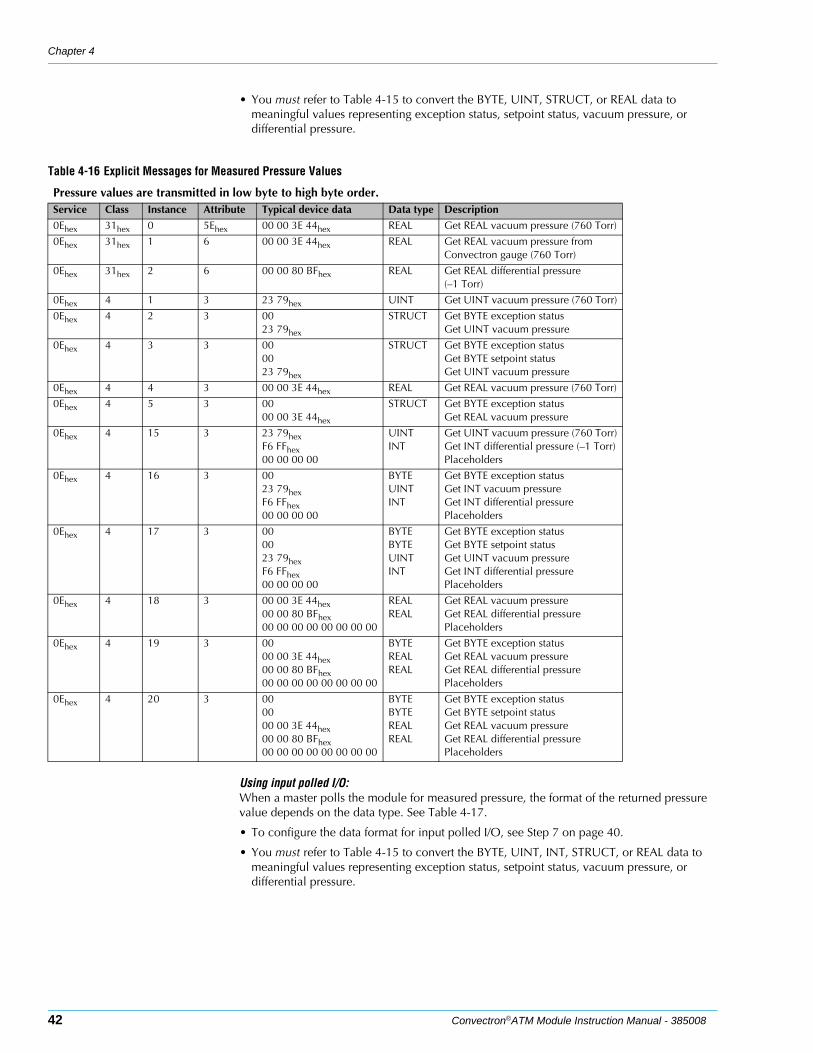
• You must refer to Table 4-15 to convert the BYTE, UINT, STRUCT, or REAL data to meaningful values representing exception status, setpoint status, vacuum pressure, or differential pressure.
Using input polled I/O:When a master polls the module for measured pressure, the format of the returned pressure value depends on the data type. See Table 4-17.
• To configure the data format for input polled I/O, see Step 7 on page 40.
• You must refer to Table 4-15 to convert the BYTE, UINT, INT, STRUCT, or REAL data to meaningful values representing exception status, setpoint status, vacuum pressure, or differential pressure.
Table 4-16 Explicit Messages for Measured Pressure Values
Pressure values are transmitted in low byte to high byte order.Service Class Instance Attribute Typical device data Data type Description
0Ehex 31hex 0 5Ehex 00 00 3E 44hex REAL Get REAL vacuum pressure (760 Torr)
0Ehex 31hex 1 6 00 00 3E 44hex REAL Get REAL vacuum pressure from Convectron gauge (760 Torr)
0Ehex 31hex 2 6 00 00 80 BFhex REAL Get REAL differential pressure(–1 Torr)
0Ehex 4 1 3 23 79hex UINT Get UINT vacuum pressure (760 Torr)
0Ehex 4 2 3 0023 79hex
STRUCT Get BYTE exception statusGet UINT vacuum pressure
0Ehex 4 3 3 000023 79hex
STRUCT Get BYTE exception statusGet BYTE setpoint statusGet UINT vacuum pressure
0Ehex 4 4 3 00 00 3E 44hex REAL Get REAL vacuum pressure (760 Torr)
0Ehex 4 5 3 0000 00 3E 44hex
STRUCT Get BYTE exception statusGet REAL vacuum pressure
0Ehex 4 15 3 23 79hexF6 FFhex00 00 00 00
UINTINT
Get UINT vacuum pressure (760 Torr)Get INT differential pressure (–1 Torr)Placeholders
0Ehex 4 16 3 0023 79hexF6 FFhex00 00 00 00
BYTE UINTINT
Get BYTE exception statusGet INT vacuum pressureGet INT differential pressurePlaceholders
0Ehex 4 17 3 000023 79hexF6 FFhex00 00 00 00
BYTEBYTEUINTINT
Get BYTE exception statusGet BYTE setpoint statusGet UINT vacuum pressureGet INT differential pressurePlaceholders
0Ehex 4 18 3 00 00 3E 44hex00 00 80 BFhex00 00 00 00 00 00 00 00
REALREAL
Get REAL vacuum pressureGet REAL differential pressurePlaceholders
0Ehex 4 19 3 0000 00 3E 44hex00 00 80 BFhex00 00 00 00 00 00 00 00
BYTEREALREAL
Get BYTE exception statusGet REAL vacuum pressureGet REAL differential pressurePlaceholders
0Ehex 4 20 3 000000 00 3E 44hex00 00 80 BFhex00 00 00 00 00 00 00 00
BYTE BYTE REALREAL
Get BYTE exception statusGet BYTE setpoint statusGet REAL vacuum pressureGet REAL differential pressurePlaceholders
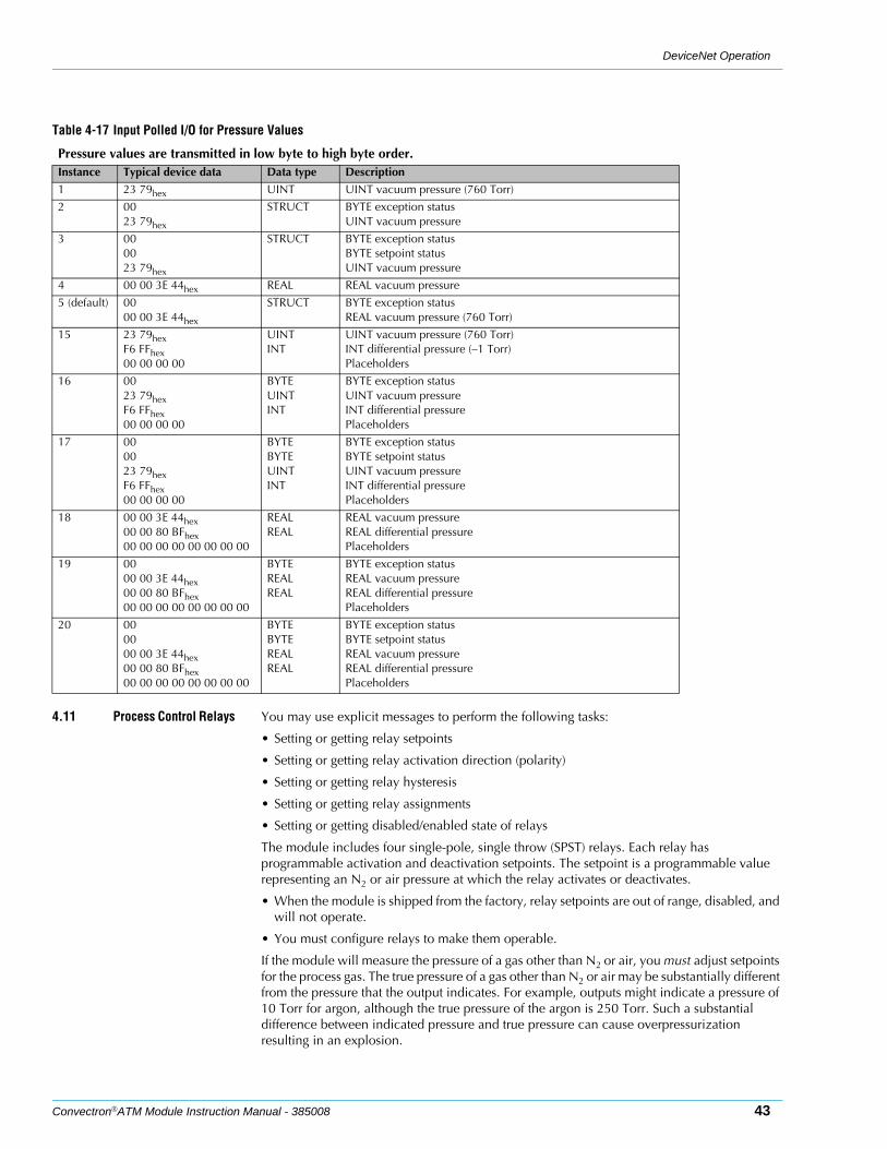
DeviceNet Operation
Convectron®ATM Module Instruction Manual - 385008 43
4.11 Process Control Relays You may use explicit messages to perform the following tasks:
• Setting or getting relay setpoints
• Setting or getting relay activation direction (polarity)
• Setting or getting relay hysteresis
• Setting or getting relay assignments
• Setting or getting disabled/enabled state of relays
The module includes four single-pole, single throw (SPST) relays. Each relay has programmable activation and deactivation setpoints. The setpoint is a programmable value representing an N2 or air pressure at which the relay activates or deactivates.
• When the module is shipped from the factory, relay setpoints are out of range, disabled, and will not operate.
• You must configure relays to make them operable.
If the module will measure the pressure of a gas other than N2 or air, you must adjust setpoints for the process gas. The true pressure of a gas other than N2 or air may be substantially different from the pressure that the output indicates. For example, outputs might indicate a pressure of 10 Torr for argon, although the true pressure of the argon is 250 Torr. Such a substantial difference between indicated pressure and true pressure can cause overpressurization resulting in an explosion.
Table 4-17 Input Polled I/O for Pressure Values
Pressure values are transmitted in low byte to high byte order.Instance Typical device data Data type Description
1 23 79hex UINT UINT vacuum pressure (760 Torr)
2 0023 79hex
STRUCT BYTE exception statusUINT vacuum pressure
3 000023 79hex
STRUCT BYTE exception statusBYTE setpoint statusUINT vacuum pressure
4 00 00 3E 44hex REAL REAL vacuum pressure
5 (default) 0000 00 3E 44hex
STRUCT BYTE exception statusREAL vacuum pressure (760 Torr)
15 23 79hexF6 FFhex00 00 00 00
UINTINT
UINT vacuum pressure (760 Torr)INT differential pressure (–1 Torr)Placeholders
16 0023 79hexF6 FFhex00 00 00 00
BYTEUINTINT
BYTE exception statusUINT vacuum pressureINT differential pressurePlaceholders
17 000023 79hexF6 FFhex00 00 00 00
BYTEBYTEUINTINT
BYTE exception statusBYTE setpoint statusUINT vacuum pressureINT differential pressurePlaceholders
18 00 00 3E 44hex00 00 80 BFhex00 00 00 00 00 00 00 00
REALREAL
REAL vacuum pressureREAL differential pressurePlaceholders
19 0000 00 3E 44hex00 00 80 BFhex00 00 00 00 00 00 00 00
BYTEREALREAL
BYTE exception statusREAL vacuum pressureREAL differential pressurePlaceholders
20 000000 00 3E 44hex00 00 80 BFhex00 00 00 00 00 00 00 00
BYTEBYTEREALREAL
BYTE exception statusBYTE setpoint statusREAL vacuum pressureREAL differential pressurePlaceholders
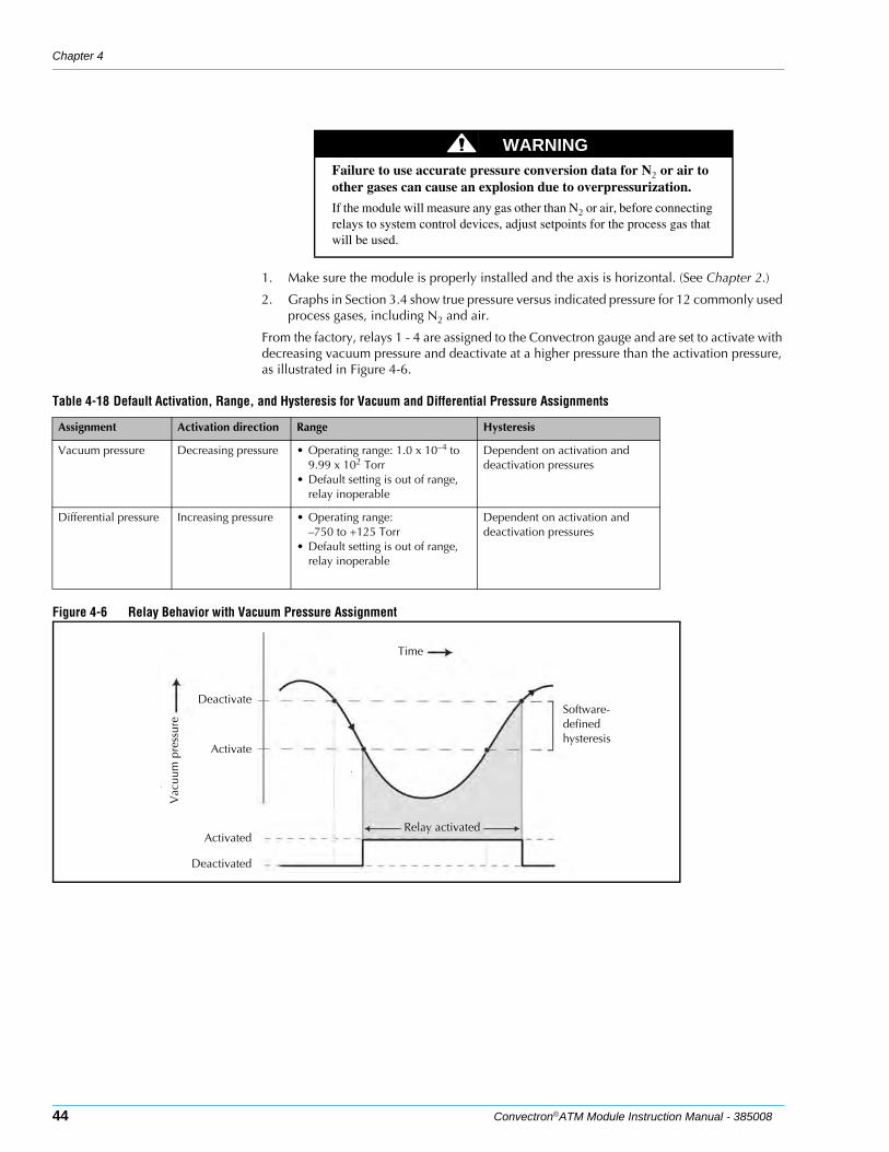
Chapter 4
44 Convectron®ATM Module Instruction Manual - 385008
1. Make sure the module is properly installed and the axis is horizontal. (See Chapter 2.)
2. Graphs in Section 3.4 show true pressure versus indicated pressure for 12 commonly used process gases, including N2 and air.
From the factory, relays 1 - 4 are assigned to the Convectron gauge and are set to activate with decreasing vacuum pressure and deactivate at a higher pressure than the activation pressure, as illustrated in Figure 4-6.
Figure 4-6 Relay Behavior with Vacuum Pressure Assignment
WARNINGFailure to use accurate pressure conversion data for N2 or air to other gases can cause an explosion due to overpressurization.
If the module will measure any gas other than N2 or air, before connecting relays to system control devices, adjust setpoints for the process gas that will be used.
Table 4-18 Default Activation, Range, and Hysteresis for Vacuum and Differential Pressure Assignments
Assignment Activation direction Range Hysteresis
Vacuum pressure Decreasing pressure • Operating range: 1.0 x 10⁻⁴ to 9.99 x 10² Torr
• Default setting is out of range, relay inoperable
Dependent on activation and deactivation pressures
Differential pressure Increasing pressure • Operating range:–750 to +125 Torr
• Default setting is out of range, relay inoperable
Dependent on activation and deactivation pressures
Deactivate
Activate
Deactivated
Activated
Software-defined hysteresis
Time
Vac
uum
pre
ssur
e
Relay activated
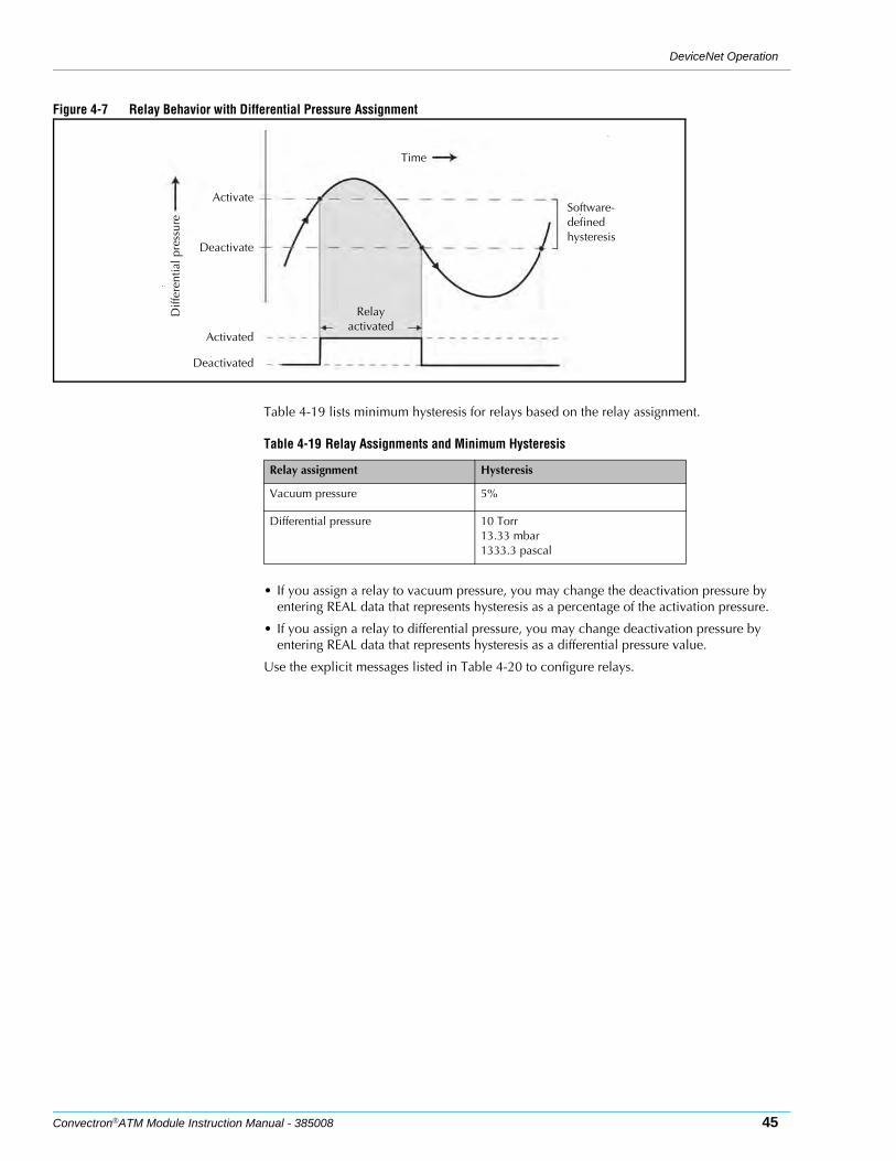
DeviceNet Operation
Convectron®ATM Module Instruction Manual - 385008 45
Figure 4-7 Relay Behavior with Differential Pressure Assignment
Table 4-19 lists minimum hysteresis for relays based on the relay assignment.
• If you assign a relay to vacuum pressure, you may change the deactivation pressure by entering REAL data that represents hysteresis as a percentage of the activation pressure.
• If you assign a relay to differential pressure, you may change deactivation pressure by entering REAL data that represents hysteresis as a differential pressure value.
Use the explicit messages listed in Table 4-20 to configure relays.
Activate
Deactivate
Deactivated
Activated
Relay activated
Time
Diff
eren
tial p
ress
ure
Software-defined hysteresis
Table 4-19 Relay Assignments and Minimum Hysteresis
Relay assignment Hysteresis
Vacuum pressure 5%
Differential pressure 10 Torr13.33 mbar1333.3 pascal
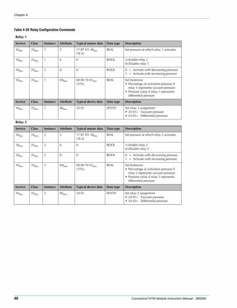
Chapter 4
46 Convectron®ATM Module Instruction Manual - 385008
Table 4-20 Relay Configuration Commands
Relay 1
Service Class Instance Attribute Typical master data Data type Description
10hex 35hex 1 5 17 B7 D1 38hex(1E-4)
REAL Set pressure at which relay 1 activates
10hex 35hex 1 6 0 BOOL 1=Enable relay 10=Disable relay 1
10hex 35hex 1 8 0 BOOL 0 = Activate with decreasing pressure1 = Activate with increasing pressure
10hex 35hex 1 0Ahex 00 00 70 41hex (15%)
REAL Set hysteresis• Percentage of activation pressure if
relay 1 represents vacuum pressure• Pressure value if relay 1 represents
differential pressure
Service Class Instance Attribute Typical device data Data type Description
10hex 35hex 1 0Ehex 24 01 EPATH Set relay 1 assignment• 24 01= Vacuum pressure• 24 02= Differential pressure
Relay 2
Service Class Instance Attribute Typical master data Data type Description
10hex 35hex 2 5 17 B7 D1 38hex(1E-4)
REAL Set pressure at which relay 2 activates
10hex 35hex 2 6 0 BOOL 1=Enable relay 20=Disable relay 2
10hex 35hex 2 8 0 BOOL 0 = Activate with decreasing pressure1 = Activate with increasing pressure
10hex 35hex 2 0Ahex 00 00 70 41hex (15%)
REAL Set hysteresis• Percentage of activation pressure if
relay 2 represents vacuum pressure• Pressure value if relay 2 represents
differential pressure
Service Class Instance Attribute Typical device data Data type Description
10hex 35hex 2 0Ehex 24 01 EPATH Set relay 2 assignment• 24 01= Vacuum pressure• 24 02= Differential pressure
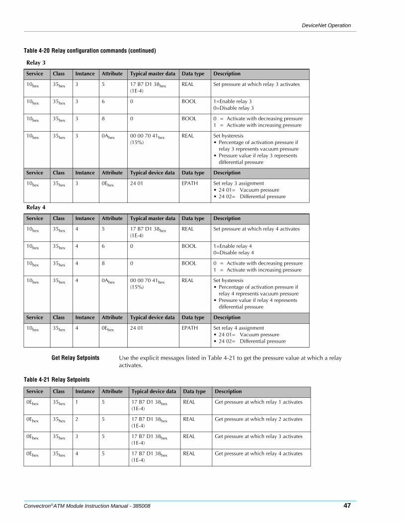
DeviceNet Operation
Convectron®ATM Module Instruction Manual - 385008 47
Get Relay Setpoints Use the explicit messages listed in Table 4-21 to get the pressure value at which a relay activates.
Table 4-20 Relay configuration commands (continued)
Relay 3
Service Class Instance Attribute Typical master data Data type Description
10hex 35hex 3 5 17 B7 D1 38hex(1E-4)
REAL Set pressure at which relay 3 activates
10hex 35hex 3 6 0 BOOL 1=Enable relay 30=Disable relay 3
10hex 35hex 3 8 0 BOOL 0 = Activate with decreasing pressure1 = Activate with increasing pressure
10hex 35hex 3 0Ahex 00 00 70 41hex (15%)
REAL Set hysteresis• Percentage of activation pressure if
relay 3 represents vacuum pressure• Pressure value if relay 3 represents
differential pressure
Service Class Instance Attribute Typical device data Data type Description
10hex 35hex 3 0Ehex 24 01 EPATH Set relay 3 assignment• 24 01= Vacuum pressure• 24 02= Differential pressure
Relay 4
Service Class Instance Attribute Typical master data Data type Description
10hex 35hex 4 5 17 B7 D1 38hex(1E-4)
REAL Set pressure at which relay 4 activates
10hex 35hex 4 6 0 BOOL 1=Enable relay 40=Disable relay 4
10hex 35hex 4 8 0 BOOL 0 = Activate with decreasing pressure1 = Activate with increasing pressure
10hex 35hex 4 0Ahex 00 00 70 41hex (15%)
REAL Set hysteresis• Percentage of activation pressure if
relay 4 represents vacuum pressure• Pressure value if relay 4 represents
differential pressure
Service Class Instance Attribute Typical device data Data type Description
10hex 35hex 4 0Ehex 24 01 EPATH Set relay 4 assignment• 24 01= Vacuum pressure• 24 02= Differential pressure
Table 4-21 Relay Setpoints
Service Class Instance Attribute Typical device data Data type Description
0Ehex 35hex 1 5 17 B7 D1 38hex(1E-4)
REAL Get pressure at which relay 1 activates
0Ehex 35hex 2 5 17 B7 D1 38hex(1E-4)
REAL Get pressure at which relay 2 activates
0Ehex 35hex 3 5 17 B7 D1 38hex(1E-4)
REAL Get pressure at which relay 3 activates
0Ehex 35hex 4 5 17 B7 D1 38hex(1E-4)
REAL Get pressure at which relay 4 activates
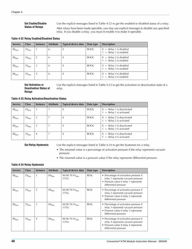
Chapter 4
48 Convectron®ATM Module Instruction Manual - 385008
Get Enable/Disable Status of Relays
Use the explicit messages listed in Table 4-22 to get the enabled or disabled status of a relay.
After relays have been made operable, you may use explicit messages to disable any specified relay. If you disable a relay, you must re-enable it to make it operable.
Get Activation or Deactivation Status of Relays
Use the explicit messages listed in Table 4-23 to get the activation or deactivation state of a relay.
Get Relay Hysteresis Use the explicit messages listed in Table 4-24 to get the hysteresis for a relay.
• The returned value is a percentage of activation pressure if the relay represents vacuum pressure.
• The returned value is a pressure value if the relay represents differential pressure.
Table 4-22 Relay Enabled/Disabled Status
Service Class Instance Attribute Typical device data Data type Description
0Ehex 35hex 1 6 0 BOOL 0 = Relay 1 is disabled1 = Relay 1 is enabled
0Ehex 35hex 2 6 0 BOOL 0 = Relay 2 is disabled1 = Relay 2 is enabled
0Ehex 35hex 3 6 0 BOOL 0 = Relay 3 is disabled1 = Relay 3 is enabled
0Ehex 35hex 4 6 0 BOOL 0 = Relay 4 is disabled1 = Relay 4 is enabled
Table 4-23 Relay Activation/Deactivation Status
Service Class Instance Attribute Typical device data Data type Description
0Ehex 35hex 1 7 0 BOOL 0 = Relay 1 is deactivated1 = Relay 1 is activated
0Ehex 35hex 2 7 0 BOOL 0 = Relay 2 is deactivated1 = Relay 2 is activated
0Ehex 35hex 3 7 0 BOOL 0 = Relay 3 is deactivated1 = Relay 3 is activated
0Ehex 35hex 4 7 0 BOOL 0 = Relay 4 is deactivated1 = Relay 4 is activated
Table 4-24 Relay Hysteresis
Service Class Instance Attribute Typical device data Data type Description
0Ehex 35hex 1 0Ahex 00 00 70 41hex (15%)
REAL • Percentage of activation pressure if relay 1 represents vacuum pressure
• Pressure value if relay 1 represents differential pressure
0Ehex 35hex 2 0Ahex 00 00 70 41hex (15%)
REAL • Percentage of activation pressure if relay 2 represents vacuum pressure
• Pressure value if relay 2 represents differential pressure
0Ehex 35hex 3 0Ahex 00 00 70 41hex (15%)
REAL • Percentage of activation pressure if relay 3 represents vacuum pressure
• Pressure value if relay 3 represents differential pressure
0Ehex 35hex 4 0Ahex 00 00 70 41hex (15%)
REAL • Percentage of activation pressure if relay 4 represents vacuum pressure
• Pressure value if relay 4 represents differential pressure
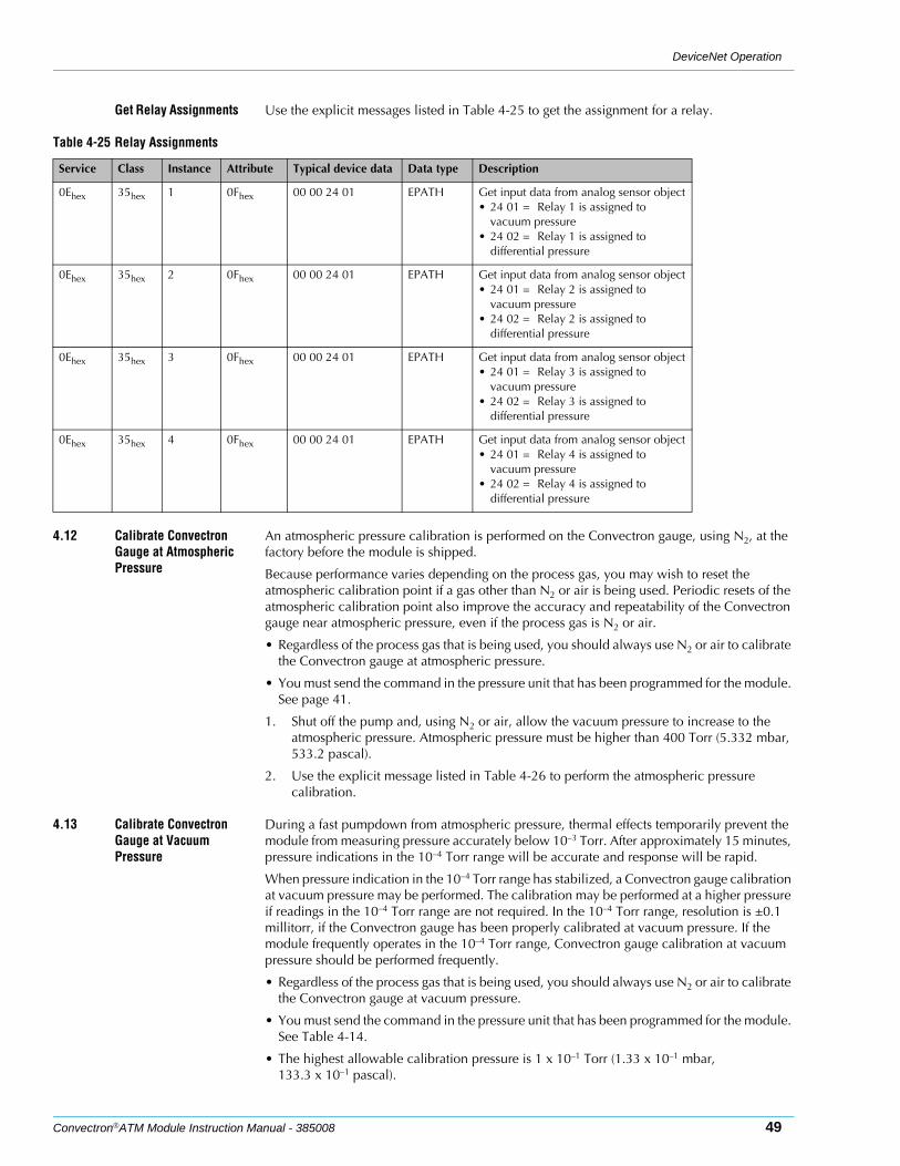
DeviceNet Operation
Convectron®ATM Module Instruction Manual - 385008 49
Get Relay Assignments Use the explicit messages listed in Table 4-25 to get the assignment for a relay.
4.12 Calibrate Convectron Gauge at Atmospheric Pressure
An atmospheric pressure calibration is performed on the Convectron gauge, using N2, at the factory before the module is shipped.
Because performance varies depending on the process gas, you may wish to reset the atmospheric calibration point if a gas other than N2 or air is being used. Periodic resets of the atmospheric calibration point also improve the accuracy and repeatability of the Convectron gauge near atmospheric pressure, even if the process gas is N2 or air.
• Regardless of the process gas that is being used, you should always use N2 or air to calibrate the Convectron gauge at atmospheric pressure.
• You must send the command in the pressure unit that has been programmed for the module. See page 41.
1. Shut off the pump and, using N2 or air, allow the vacuum pressure to increase to the atmospheric pressure. Atmospheric pressure must be higher than 400 Torr (5.332 mbar, 533.2 pascal).
2. Use the explicit message listed in Table 4-26 to perform the atmospheric pressure calibration.
4.13 Calibrate Convectron Gauge at Vacuum Pressure
During a fast pumpdown from atmospheric pressure, thermal effects temporarily prevent the module from measuring pressure accurately below 10–3 Torr. After approximately 15 minutes, pressure indications in the 10–4 Torr range will be accurate and response will be rapid.
When pressure indication in the 10–4 Torr range has stabilized, a Convectron gauge calibration at vacuum pressure may be performed. The calibration may be performed at a higher pressure if readings in the 10–4 Torr range are not required. In the 10–4 Torr range, resolution is ±0.1 millitorr, if the Convectron gauge has been properly calibrated at vacuum pressure. If the module frequently operates in the 10–4 Torr range, Convectron gauge calibration at vacuum pressure should be performed frequently.
• Regardless of the process gas that is being used, you should always use N2 or air to calibrate the Convectron gauge at vacuum pressure.
• You must send the command in the pressure unit that has been programmed for the module. See Table 4-14.
• The highest allowable calibration pressure is 1 x 10⁻¹ Torr (1.33 x 10⁻¹ mbar, 133.3 x 10⁻¹ pascal).
Table 4-25 Relay Assignments
Service Class Instance Attribute Typical device data Data type Description
0Ehex 35hex 1 0Fhex 00 00 24 01 EPATH Get input data from analog sensor object• 24 01 = Relay 1 is assigned to
vacuum pressure• 24 02 = Relay 1 is assigned to
differential pressure
0Ehex 35hex 2 0Fhex 00 00 24 01 EPATH Get input data from analog sensor object• 24 01 = Relay 2 is assigned to
vacuum pressure• 24 02 = Relay 2 is assigned to
differential pressure
0Ehex 35hex 3 0Fhex 00 00 24 01 EPATH Get input data from analog sensor object• 24 01 = Relay 3 is assigned to
vacuum pressure• 24 02 = Relay 3 is assigned to
differential pressure
0Ehex 35hex 4 0Fhex 00 00 24 01 EPATH Get input data from analog sensor object• 24 01 = Relay 4 is assigned to
vacuum pressure• 24 02 = Relay 4 is assigned to
differential pressure
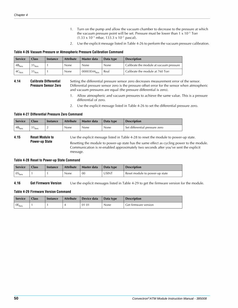
Chapter 4
50 Convectron®ATM Module Instruction Manual - 385008
1. Turn on the pump and allow the vacuum chamber to decrease to the pressure at which the vacuum pressure point will be set. Pressure must be lower than 1 x 10⁻¹ Torr (1.33 x 10⁻¹ mbar, 133.3 x 10⁻¹ pascal).
2. Use the explicit message listed in Table 4-26 to perform the vacuum pressure calibration.
4.14 Calibrate Differential Pressure Sensor Zero
Setting the differential pressure sensor zero decreases measurement error of the sensor. Differential pressure sensor zero is the pressure offset error for the sensor when atmospheric and vacuum pressures are equal (the pressure differential is zero).
1. Allow atmospheric and vacuum pressures to achieve the same value. This is a pressure differential of zero.
2. Use the explicit message listed in Table 4-26 to set the differential pressure zero.
4.15 Reset Module to Power-up State
Use the explicit message listed in Table 4-28 to reset the module to power-up state.
Resetting the module to power-up state has the same effect as cycling power to the module. Communication is re-enabled approximately two seconds after you’ve sent the explicit message.
4.16 Get Firmware Version Use the explicit messages listed in Table 4-29 to get the firmware version for the module.
Table 4-26 Vacuum Pressure or Atmospheric Pressure Calibration Command
Service Class Instance Attribute Master data Data type Description
4Bhex 31hex 1 None None None Calibrate the module at vacuum pressure
4Chex 31hex 1 None 00003E44hex Real Calibrate the module at 760 Torr
Table 4-27 Differential Pressure Zero Command
Service Class Instance Attribute Master data Data type Description
4Bhex 31hex 2 None None None Set differential pressure zero
Table 4-28 Reset to Power-up State Command
Service Class Instance Attribute Master data Data type Description
05hex 1 1 None 00 USINT Reset module to power-up state
Table 4-29 Firmware Version Command
Service Class Instance Attribute Device data Data type Description
0Ehex 1 1 4 01 01 None Get firmware version
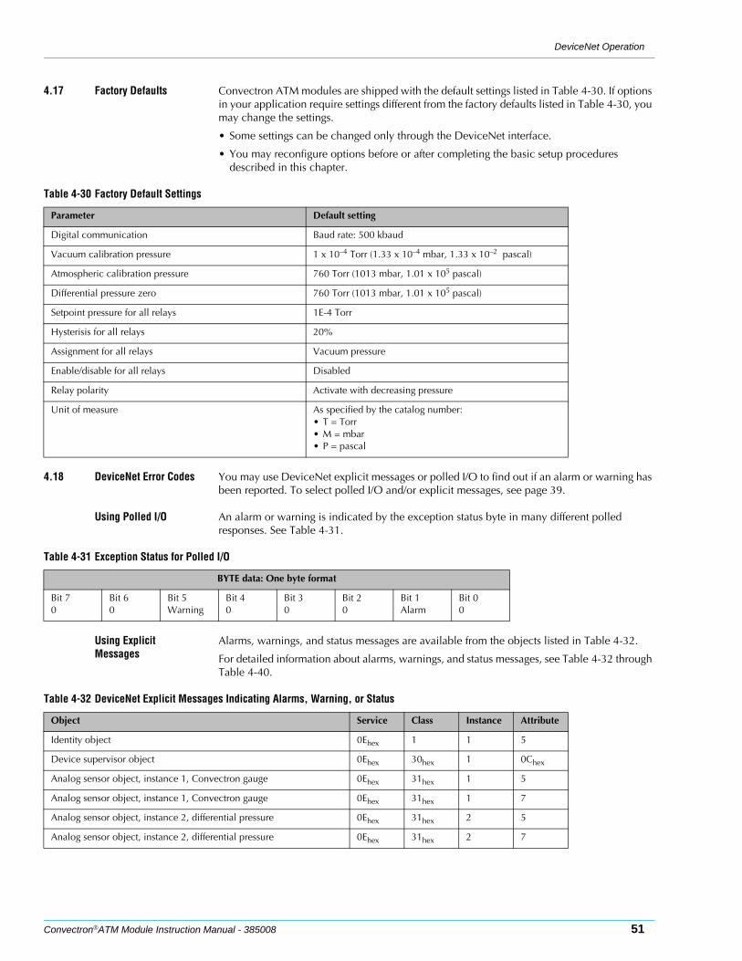
DeviceNet Operation
Convectron®ATM Module Instruction Manual - 385008 51
4.17 Factory Defaults Convectron ATM modules are shipped with the default settings listed in Table 4-30. If options in your application require settings different from the factory defaults listed in Table 4-30, you may change the settings.
• Some settings can be changed only through the DeviceNet interface.
• You may reconfigure options before or after completing the basic setup procedures described in this chapter.
4.18 DeviceNet Error Codes You may use DeviceNet explicit messages or polled I/O to find out if an alarm or warning has been reported. To select polled I/O and/or explicit messages, see page 39.
Using Polled I/O An alarm or warning is indicated by the exception status byte in many different polled responses. See Table 4-31.
Using Explicit Messages
Alarms, warnings, and status messages are available from the objects listed in Table 4-32.
For detailed information about alarms, warnings, and status messages, see Table 4-32 through Table 4-40.
Table 4-30 Factory Default Settings
Parameter Default setting
Digital communication Baud rate: 500 kbaud
Vacuum calibration pressure 1 x 10⁻⁴ Torr (1.33 x 10⁻⁴ mbar, 1.33 x 10⁻² pascal)
Atmospheric calibration pressure 760 Torr (1013 mbar, 1.01 x 10⁵ pascal)
Differential pressure zero 760 Torr (1013 mbar, 1.01 x 10⁵ pascal)
Setpoint pressure for all relays 1E-4 Torr
Hysterisis for all relays 20%
Assignment for all relays Vacuum pressure
Enable/disable for all relays Disabled
Relay polarity Activate with decreasing pressure
Unit of measure As specified by the catalog number:• T = Torr• M = mbar• P = pascal
Table 4-31 Exception Status for Polled I/O
BYTE data: One byte format
Bit 70
Bit 60
Bit 5Warning
Bit 40
Bit 30
Bit 20
Bit 1Alarm
Bit 00
Table 4-32 DeviceNet Explicit Messages Indicating Alarms, Warning, or Status
Object Service Class Instance Attribute
Identity object 0Ehex 1 1 5
Device supervisor object 0Ehex 30hex 1 0Chex
Analog sensor object, instance 1, Convectron gauge 0Ehex 31hex 1 5
Analog sensor object, instance 1, Convectron gauge 0Ehex 31hex 1 7
Analog sensor object, instance 2, differential pressure 0Ehex 31hex 2 5
Analog sensor object, instance 2, differential pressure 0Ehex 31hex 2 7

Chapter 4
52 Convectron®ATM Module Instruction Manual - 385008
Table 4-33 Status and Fault Information from Identity Object
Service Class Instance Attribute Typical device data Data type Description
0Ehex 1 1 5 00 00 WORD Status and fault information
Table 4-34 Troubleshooting Status and Fault Information
Service Class Instance Attribute Bit Cause Solution
0Ehex 1 1 5 0 An object is allocated. No solution necessary.
0Ehex 1 1 5 2 Device is configured. No solution necessary.
0Ehex 1 1 5 8 • Convectron gauge cannot be calibrated at atmospheric pressure.
• Convectron gauge cannot be calibrated at vacuum pressure.
• If Convectron gauge cannot be calibrated at atmospheric pressure, make sure vacuum pressure = atmospheric pressure, then recalibrate (see page 49).
• If Convectron gauge cannot be calibrated at vacuum pressure, make sure vacuum pressure ≤ 1 x 10⁻⁴ Torr (1.33 x 10⁻⁴ mbar, 1.33 x 10⁻² pascal), then recalibrate (see page 49).
0Ehex 1 1 5 11 Convectron gauge or differential pressure sensor is inoperable.
Replace the Convectron gauge (see page 58).
Table 4-35 Exception Status from Device Supervisor Object
Service Class Instance Attribute Typical device data Data type Description
0Ehex 30hex 1 0Chex 0 BYTE Get exception status
Table 4-36 Troubleshooting Exception Status
Service Class Instance Attribute Bit Cause Solution
0Ehex 1 1 0Chex 1 Convectron gauge or differential pressure sensor is inoperable.
Replace gauge assembly (see page 58).
0Ehex 1 1 0Chex 5 • Convectron gauge cannot be calibrated at atmospheric pressure.
• Convectron gauge cannot be calibrated at vacuum pressure.
• If the Convectron gauge cannot be calibrated at atmospheric pressure, make sure the atmospheric pressure > 400 Torr (5.332 mbar, 533.2 pascal), then recalibrate (see page 49).
• If the Convectron gauge cannot be calibrated at vacuum pressure, make sure the vacuum pressure > 1 x 10⁻¹ Torr (1.33 x 10⁻¹ mbar, 133.3 x 10⁻¹ pascal), then recalibrate (see page 49).
Table 4-37 Reading Valid, Status, Alarm, and Warning Information fro Analog Sensor Object, Instance 1, Convectron Gauge
Service Class Instance Attribute Typical device data Data type Description
0Ehex 31hex 1 5 1 BOOL Get reading validity, 0 or 1
0Ehex 31hex 1 7 0 BYTE Get status, alarm or warning
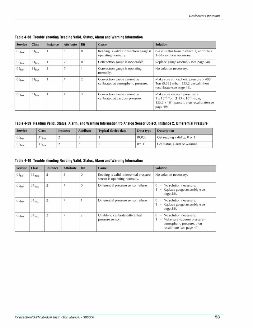
DeviceNet Operation
Convectron®ATM Module Instruction Manual - 385008 53
.
Table 4-38 Trouble shooting Reading Valid, Status, Alarm and Warning Information
Service Class Instance Attribute Bit Cause Solution
0Ehex 31hex 1 5 0 Reading is valid, Convectron gauge is operating normally.
0=Get status from instance 1, attribute 7.1=No solution necessary.
0Ehex 31hex 1 7 0 Convectron gauge is inoperable. Replace gauge assembly (see page 58).
0Ehex 31hex 1 7 1 Convectron gauge is operating normally.
No solution necessary.
0Ehex 31hex 1 7 2 Convectron gauge cannot be calibrated at atmospheric pressure.
Make sure atmospheric pressure > 400 Torr (5.332 mbar, 533.2 pascal), then recalibrate (see page 49).
0Ehex 31hex 1 7 3 Convectron gauge cannot be calibrated at vacuum pressure.
Make sure vacuum pressure > 1 x 10⁻¹ Torr (1.33 x 10⁻¹ mbar, 133.3 x 10⁻¹ pascal), then recalibrate (see page 49).
Table 4-39 Reading Valid, Status, Alarm, and Warning Information fro Analog Sensor Object, Instance 2, Differential Pressure
Service Class Instance Attribute Typical device data Data type Description
0Ehex 31hex 2 5 1 BOOL Get reading validity, 0 or 1
0Ehex 31hex 2 7 0 BYTE Get status, alarm or warning
Table 4-40 Trouble shooting Reading Valid, Status, Alarm and Warning Information
Service Class Instance Attribute Bit Cause Solution
0Ehex 31hex 2 5 0 Reading is valid, differential pressure sensor is operating normally.
No solution necessary.
0Ehex 31hex 2 7 0 Differential pressure sensor failure. 0 = No solution necessary.1 = Replace gauge assembly (see
page 58).
0Ehex 31hex 2 7 1 Differential pressure sensor failure. 0 = No solution necessary.1 = Replace gauge assembly (see
page 58).
0Ehex 31hex 2 7 2 Unable to calibrate differential pressure sensor.
0 = No solution necessary.1 = Make sure vacuum pressure =
atmospheric pressure, then recalibrate (see page 49).

Chapter 4
54 Convectron®ATM Module Instruction Manual - 385008
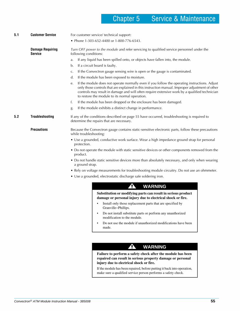
Convectron® ATM Module Instruction Manual - 385008 55
Chapter 5 Service & Maintenance
5.1 Customer Service For customer service/ technical support:
• Phone 1-303-652-4400 or 1-800-776-6543.
Damage Requiring Service
Turn OFF power to the module and refer servicing to qualified service personnel under the following conditions:
a. If any liquid has been spilled onto, or objects have fallen into, the module.
b. If a circuit board is faulty.
c. If the Convectron gauge sensing wire is open or the gauge is contaminated.
d. If the module has been exposed to moisture.
e. If the module does not operate normally even if you follow the operating instructions. Adjust only those controls that are explained in this instruction manual. Improper adjustment of other controls may result in damage and will often require extensive work by a qualified technician to restore the module to its normal operation.
f. If the module has been dropped or the enclosure has been damaged.
g. If the module exhibits a distinct change in performance.
5.2 Troubleshooting If any of the conditions described on page 55 have occurred, troubleshooting is required to determine the repairs that are necessary.
Precautions Because the Convectron gauge contains static-sensitive electronic parts, follow these precautions while troubleshooting:
• Use a grounded, conductive work surface. Wear a high impedance ground strap for personal protection.
• Do not operate the module with static sensitive devices or other components removed from the product.
• Do not handle static sensitive devices more than absolutely necessary, and only when wearing a ground strap.
• Rely on voltage measurements for troubleshooting module circuitry. Do not use an ohmmeter.
• Use a grounded, electrostatic discharge safe soldering iron.
WARNINGSubstitution or modifying parts can result in serious product damage or personal injury due to electrical shock or fire.
• Install only those replacement parts that are specified by Granville−Phillips.
• Do not install substitute parts or perform any unauthorized modification to the module.
• Do not use the module if unauthorized modifications have been made.
WARNINGFailure to perform a safety check after the module has been repaired can result in serious property damage or personal injury due to electrical shock or fire.
If the module has been repaired, before putting it back into operation, make sure a qualified service person performs a safety check.

Chapter 5
56 Convectron® ATM Module Instruction Manual - 385008
Symptoms, Causes, and Solutions
Table 5-1 Failure Symptoms, Causes, and Solutions
Symptom Possible causes Solution
Pressure reading is too high. • Conductance in connection to vacuum chamber is inadequate.
• Plumbing to module leaks or is contaminated.
• Chamber pressure is too high due to leak, contamination, or pump failure.
• Power supply cable is improperly connected or faulty.
• If conductance is inadequate, reconnect Convectron gauge port to vacuum chamber (page 17).
• If plumbing leaks or is contaminated, clean, repair or replace plumbing.
• If pump failed, repair or replace it.• If cable is improperly connected or
faulty, repair or replace cable (page 17).
Pressure reading is inaccurate. • Module is not calibrated for the process gas that is being used.
• Module is not mounted horizontally.• Convectron gauge or differential
pressure sensor is damaged (for example, by reactive gas) or contaminated.
• Temperature or mechanical vibration is extreme.
• If Convectron gauge is out of calibration, recalibrate it for the process gas that is being used.
• If module is not mounted horizontally, re-mount it.
• If Convectron gauge is damaged, replace it.
• If Convectron gauge is contaminated, return it to factory.
• If temperature or vibration is extreme, relocate module or eliminate source of heat or vibration.
Indicated pressure is different than pressure indications from other measurement devices.
• Process gas is a not the gas that the user anticipated using in the system.
• Convectron gauge is defective.
• If the process gas is not what was anticipated, calibrate Convectron gauge for gas that is being used.
• If Convectron gauge is defective, return it to factory. (see Section 5.6)
Relay will not activate. • A circuit board is faulty.• Setpoints are misconfigured.
• Return module to factory (see Section 5.6)
• Verify setpoint configuration (see Section 4.11)
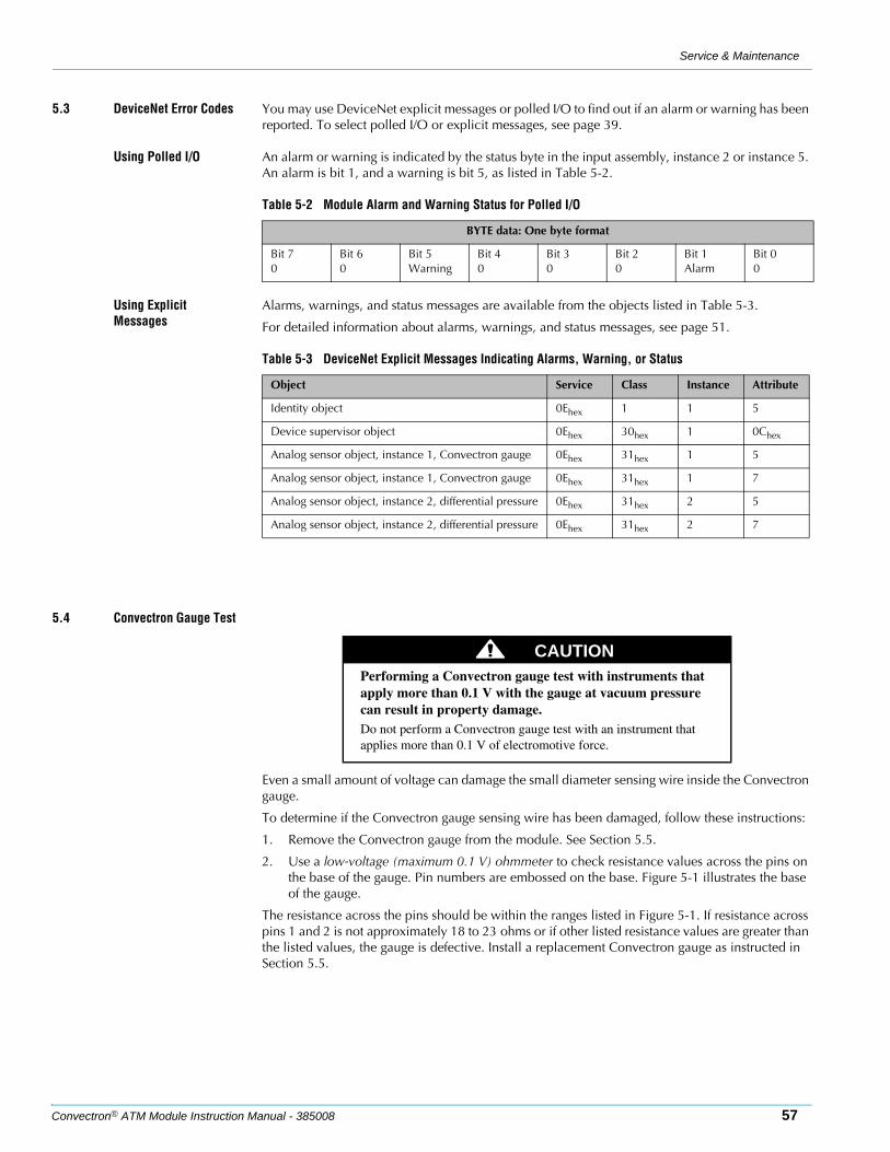
Service & Maintenance
Convectron® ATM Module Instruction Manual - 385008 57
5.3 DeviceNet Error Codes You may use DeviceNet explicit messages or polled I/O to find out if an alarm or warning has been reported. To select polled I/O or explicit messages, see page 39.
Using Polled I/O An alarm or warning is indicated by the status byte in the input assembly, instance 2 or instance 5. An alarm is bit 1, and a warning is bit 5, as listed in Table 5-2.
Using Explicit Messages
Alarms, warnings, and status messages are available from the objects listed in Table 5-3.
For detailed information about alarms, warnings, and status messages, see page 51.
5.4 Convectron Gauge Test
Even a small amount of voltage can damage the small diameter sensing wire inside the Convectron gauge.
To determine if the Convectron gauge sensing wire has been damaged, follow these instructions:
1. Remove the Convectron gauge from the module. See Section 5.5.
2. Use a low-voltage (maximum 0.1 V) ohmmeter to check resistance values across the pins on the base of the gauge. Pin numbers are embossed on the base. Figure 5-1 illustrates the base of the gauge.
The resistance across the pins should be within the ranges listed in Figure 5-1. If resistance across pins 1 and 2 is not approximately 18 to 23 ohms or if other listed resistance values are greater than the listed values, the gauge is defective. Install a replacement Convectron gauge as instructed in Section 5.5.
Table 5-2 Module Alarm and Warning Status for Polled I/O
BYTE data: One byte format
Bit 70
Bit 60
Bit 5Warning
Bit 40
Bit 30
Bit 20
Bit 1Alarm
Bit 00
Table 5-3 DeviceNet Explicit Messages Indicating Alarms, Warning, or Status
Object Service Class Instance Attribute
Identity object 0Ehex 1 1 5
Device supervisor object 0Ehex 30hex 1 0Chex
Analog sensor object, instance 1, Convectron gauge 0Ehex 31hex 1 5
Analog sensor object, instance 1, Convectron gauge 0Ehex 31hex 1 7
Analog sensor object, instance 2, differential pressure 0Ehex 31hex 2 5
Analog sensor object, instance 2, differential pressure 0Ehex 31hex 2 7
CAUTIONPerforming a Convectron gauge test with instruments that apply more than 0.1 V with the gauge at vacuum pressure can result in property damage.Do not perform a Convectron gauge test with an instrument that applies more than 0.1 V of electromotive force.
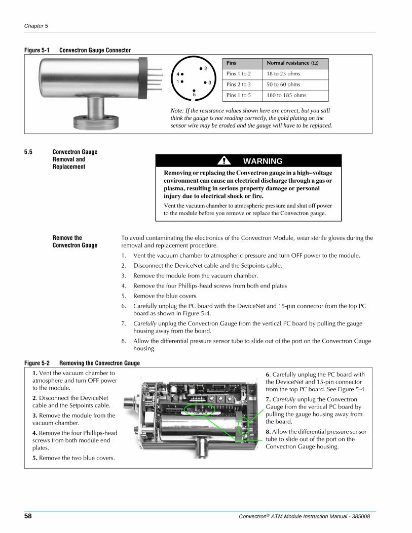
Chapter 5
58 Convectron® ATM Module Instruction Manual - 385008
Figure 5-1 Convectron Gauge Connector
5.5 Convectron Gauge Removal and Replacement
Remove the Convectron Gauge
To avoid contaminating the electronics of the Convectron Module, wear sterile gloves during the removal and replacement procedure.
1. Vent the vacuum chamber to atmospheric pressure and turn OFF power to the module.
2. Disconnect the DeviceNet cable and the Setpoints cable.
3. Remove the module from the vacuum chamber.
4. Remove the four Phillips-head screws from both end plates
5. Remove the blue covers.
6. Carefully unplug the PC board with the DeviceNet and 15-pin connector from the top PC board as shown in Figure 5-4.
7. Carefully unplug the Convectron Gauge from the vertical PC board by pulling the gauge housing away from the board.
8. Allow the differential pressure sensor tube to slide out of the port on the Convectron Gauge housing.
Figure 5-2 Removing the Convectron Gauge
Pins Normal resistance (Ω)
Pins 1 to 2 18 to 23 ohms
Pins 2 to 3 50 to 60 ohms
Pins 1 to 5 180 to 185 ohms
Note: If the resistance values shown here are correct, but you still think the gauge is not reading correctly, the gold plating on the sensor wire may be eroded and the gauge will have to be replaced.
WARNINGRemoving or replacing the Convectron gauge in a high−voltage environment can cause an electrical discharge through a gas or plasma, resulting in serious property damage or personal injury due to electrical shock or fire.
Vent the vacuum chamber to atmospheric pressure and shut off power to the module before you remove or replace the Convectron gauge.
1. Vent the vacuum chamber to atmosphere and turn OFF power to the module.
2. Disconnect the DeviceNet cable and the Setpoints cable.
3. Remove the module from the vacuum chamber.
4. Remove the four Phillips-head screws from both module end plates.
5. Remove the two blue covers.
6. Carefully unplug the PC board with the DeviceNet and 15-pin connector from the top PC board. See Figure 5-4.
7. Carefully unplug the Convectron Gauge from the vertical PC board by pulling the gauge housing away from the board.
8. Allow the differential pressure sensor tube to slide out of the port on the Convectron Gauge housing.
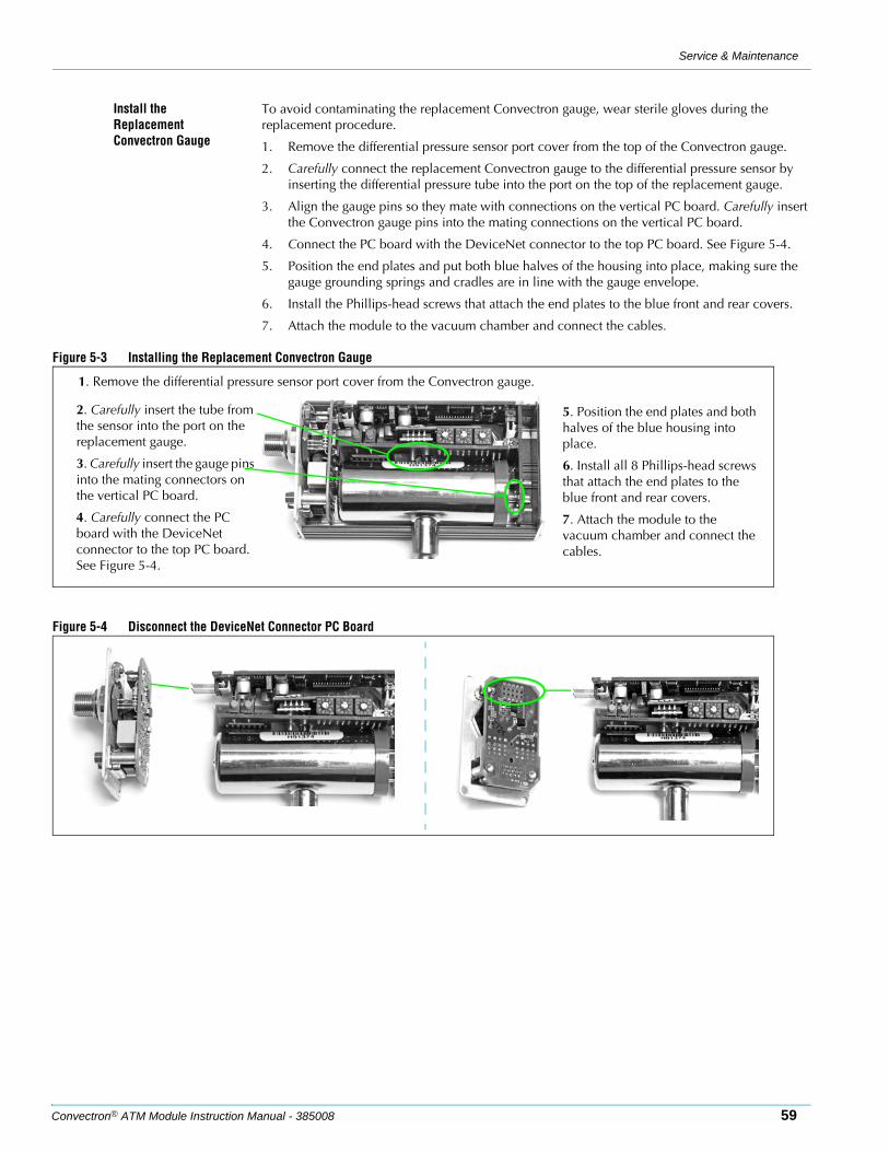
Service & Maintenance
Convectron® ATM Module Instruction Manual - 385008 59
Install the Replacement Convectron Gauge
To avoid contaminating the replacement Convectron gauge, wear sterile gloves during the replacement procedure.
1. Remove the differential pressure sensor port cover from the top of the Convectron gauge.
2. Carefully connect the replacement Convectron gauge to the differential pressure sensor by inserting the differential pressure tube into the port on the top of the replacement gauge.
3. Align the gauge pins so they mate with connections on the vertical PC board. Carefully insert the Convectron gauge pins into the mating connections on the vertical PC board.
4. Connect the PC board with the DeviceNet connector to the top PC board. See Figure 5-4.
5. Position the end plates and put both blue halves of the housing into place, making sure the gauge grounding springs and cradles are in line with the gauge envelope.
6. Install the Phillips-head screws that attach the end plates to the blue front and rear covers.
7. Attach the module to the vacuum chamber and connect the cables.
Figure 5-3 Installing the Replacement Convectron Gauge
Figure 5-4 Disconnect the DeviceNet Connector PC Board
2. Carefully insert the tube from the sensor into the port on the replacement gauge.
3. Carefully insert the gauge pins into the mating connectors on the vertical PC board.
4. Carefully connect the PC board with the DeviceNet connector to the top PC board. See Figure 5-4.
5. Position the end plates and both halves of the blue housing into place.
6. Install all 8 Phillips-head screws that attach the end plates to the blue front and rear covers.
7. Attach the module to the vacuum chamber and connect the cables.
1. Remove the differential pressure sensor port cover from the Convectron gauge.
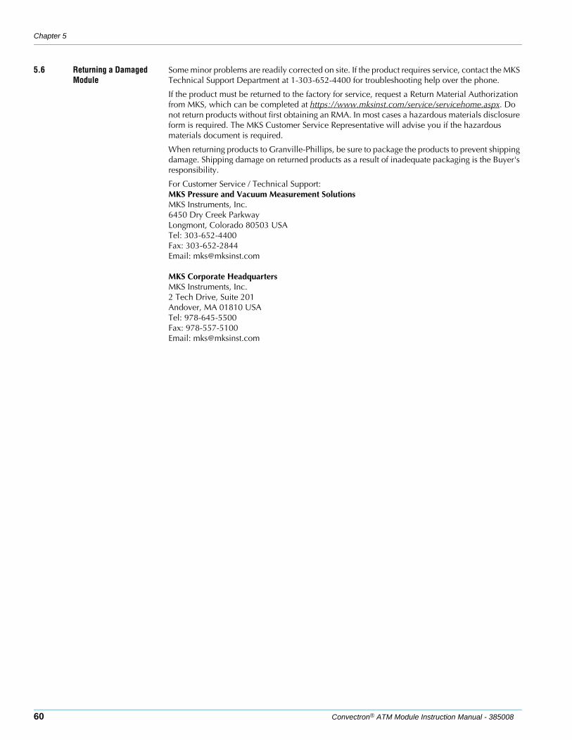
Chapter 5
60 Convectron® ATM Module Instruction Manual - 385008
5.6 Returning a Damaged Module
Some minor problems are readily corrected on site. If the product requires service, contact the MKS Technical Support Department at 1-303-652-4400 for troubleshooting help over the phone.
If the product must be returned to the factory for service, request a Return Material Authorization from MKS, which can be completed at https://www.mksinst.com/service/servicehome.aspx. Do not return products without first obtaining an RMA. In most cases a hazardous materials disclosure form is required. The MKS Customer Service Representative will advise you if the hazardous materials document is required.
When returning products to Granville-Phillips, be sure to package the products to prevent shipping damage. Shipping damage on returned products as a result of inadequate packaging is the Buyer's responsibility.
For Customer Service / Technical Support:MKS Pressure and Vacuum Measurement SolutionsMKS Instruments, Inc.6450 Dry Creek ParkwayLongmont, Colorado 80503 USATel: 303-652-4400Fax: 303-652-2844Email: [email protected]
MKS Corporate HeadquartersMKS Instruments, Inc.2 Tech Drive, Suite 201Andover, MA 01810 USATel: 978-645-5500Fax: 978-557-5100Email: [email protected]
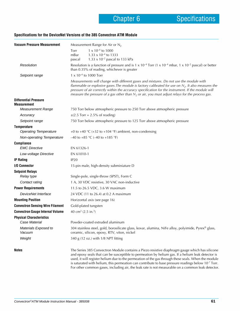
Convectron®ATM Module Instruction Manual - 385008 61
Chapter 6 Specifications
Specifications for the DeviceNet Versions of the 385 Convectron ATM Module
Vacuum Pressure Measurement Measurement Range for Air or N2
Torr 1 x 10⁻⁴ to 1000mBar 1.33 x 10⁻⁴ to 1333pascal 1.33 x 10⁻² pascal to 133 kPa
Resolution Resolution is a function of pressure and is 1 x 10⁻⁴ Torr (1 x 10⁻⁴ mbar, 1 x 10⁻² pascal) or better than 0.35% of reading, whichever is greater
Setpoint range 1 x 10⁻⁴ to 1000 Torr
Measurements will change with different gases and mixtures. Do not use the module with flammable or explosive gases.The module is factory calibrated for use on N2. It also measures the pressure of air correctly within the accuracy specification for the instrument. If the module will measure the pressure of a gas other than N2 or air, you must adjust relays for the process gas.
Differential Pressure Measurement
Measurement Range 750 Torr below atmospheric pressure to 250 Torr above atmospheric pressure
Accuracy ±(2.5 Torr + 2.5% of reading)
Setpoint range 750 Torr below atmospheric pressure to 125 Torr above atmospheric pressure
TemperatureOperating Temperature +0 to +40 °C (+32 to +104 °F) ambient, non-condensing
Non-operating Temperature –40 to +85 °C (–40 to +185 °F)
ComplianceEMC Directive EN 61326-1
Low-voltage Directive EN 61010-1
IP Rating IP20
I/O Connector 15-pin male, high-density subminiature D
Setpoint RelaysRelay type Single-pole, single-throw (SPST), Form C
Contact rating 1 A, 30 VDC resistive, 30 VAC non-inductive
Power Requirements 11.5 to 26.5 VDC, 3.6 W maximum
DeviceNet Interface 24 VDC (11 to 26.4) at 0.2 A maximum
Mounting Position Horizontal axis (see page 16)
Convectron Sensing Wire Filament Gold-plated tungsten
Convectron Gauge Internal Volume 40 cm3 (2.5 in.3)
Physical CharacteristicsCase Material Powder-coated extruded aluminum
Materials Exposed to Vacuum
304 stainless steel, gold, borosilicate glass, kovar, alumina, NiFe alloy, polyimide, Pyrex® glass, ceramic, silicon, epoxy, RTV, viton, nickel
Weight 340 g (12 oz.) with 1/8 NPT fitting
Notes The Series 385 Convectron Module contains a Piezo resistive diaphragm gauge which has silicone and epoxy seals that can be susceptible to permeation by helium gas. If a helium leak detector is used, it will register helium due to the permeation of the gas through these seals. When the module is saturated with helium, this permeation can contribute to base pressure readings below 10-7 Torr. For other common gases, including air, the leak rate is not measurable on a common leak detector.
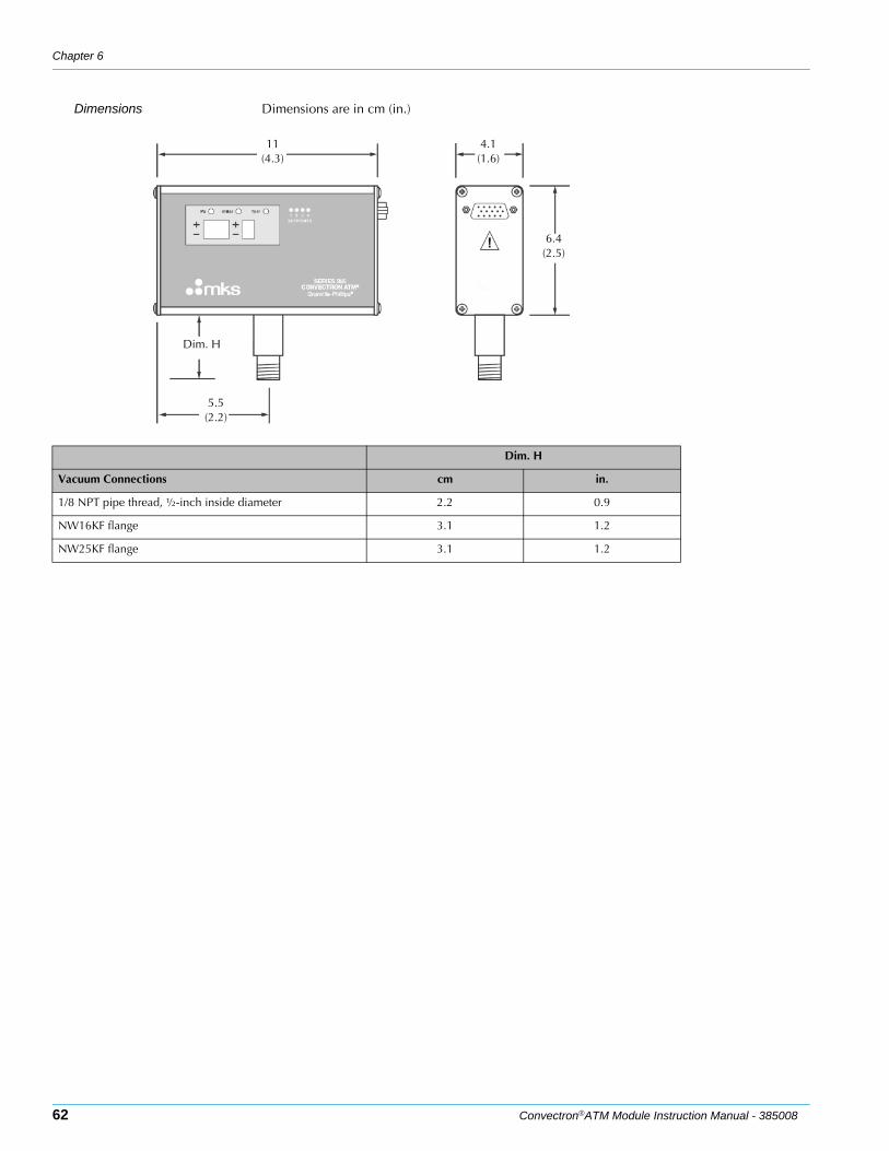
Chapter 6
62 Convectron®ATM Module Instruction Manual - 385008
Dimensions Dimensions are in cm (in.)
11(4.3)
4.1(1.6)
6.4(2.5)
5.5(2.2)
Dim. H
Dim. H
Vacuum Connections cm in.
1/8 NPT pipe thread, ½-inch inside diameter 2.2 0.9
NW16KF flange 3.1 1.2
NW25KF flange 3.1 1.2
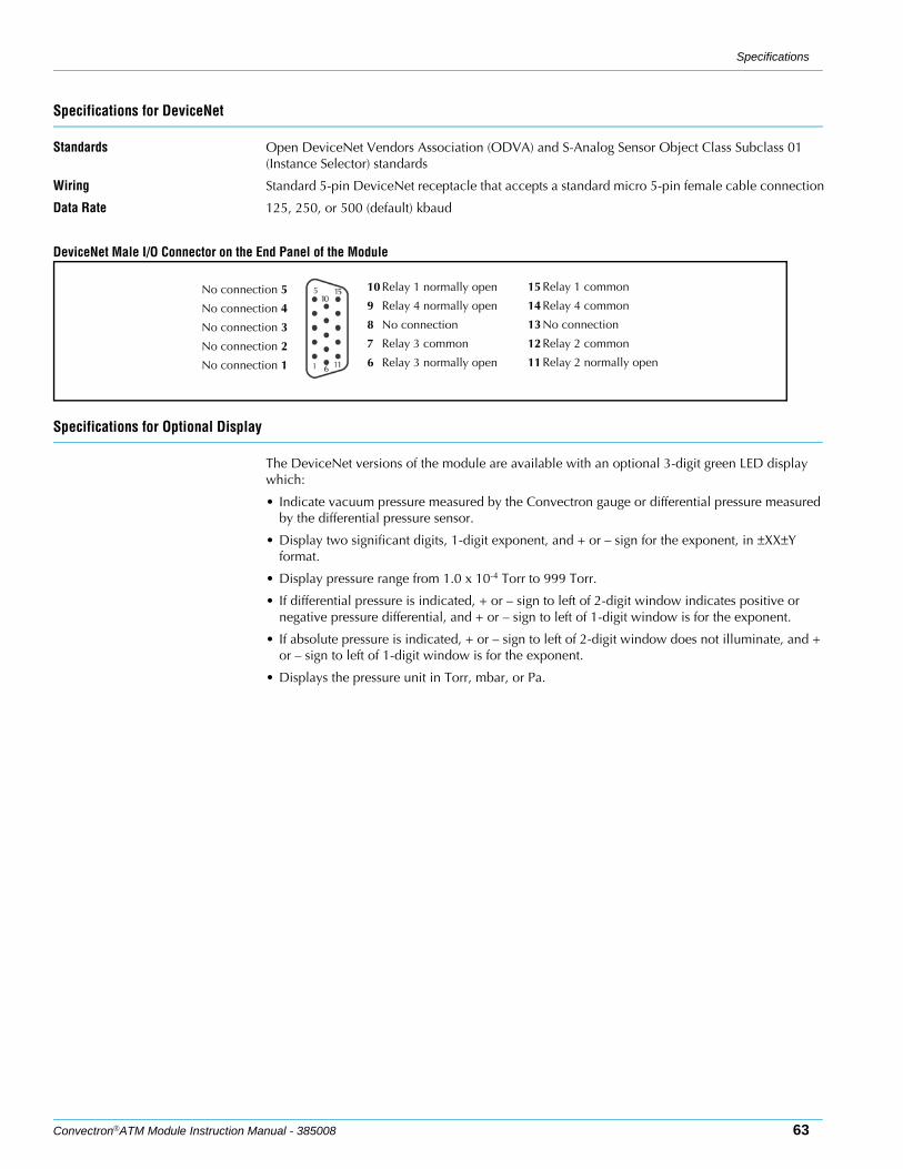
Specifications
Convectron®ATM Module Instruction Manual - 385008 63
Specifications for DeviceNet
Standards Open DeviceNet Vendors Association (ODVA) and S-Analog Sensor Object Class Subclass 01 (Instance Selector) standards
Wiring Standard 5-pin DeviceNet receptacle that accepts a standard micro 5-pin female cable connection
Data Rate 125, 250, or 500 (default) kbaud
DeviceNet Male I/O Connector on the End Panel of the Module
Specifications for Optional Display
The DeviceNet versions of the module are available with an optional 3-digit green LED display which:
• Indicate vacuum pressure measured by the Convectron gauge or differential pressure measured by the differential pressure sensor.
• Display two significant digits, 1-digit exponent, and + or – sign for the exponent, in ±XX±Y format.
• Display pressure range from 1.0 x 10⁻⁴ Torr to 999 Torr.
• If differential pressure is indicated, + or – sign to left of 2-digit window indicates positive or negative pressure differential, and + or – sign to left of 1-digit window is for the exponent.
• If absolute pressure is indicated, + or – sign to left of 2-digit window does not illuminate, and + or – sign to left of 1-digit window is for the exponent.
• Displays the pressure unit in Torr, mbar, or Pa.
No connection 5
No connection 4
No connection 3
No connection 2
No connection 1
15 Relay 1 common
14 Relay 4 common
13 No connection
12 Relay 2 common
11 Relay 2 normally open
10 Relay 1 normally open
9 Relay 4 normally open
8 No connection
7 Relay 3 common
6 Relay 3 normally open

Chapter 6
64 Convectron®ATM Module Instruction Manual - 385008
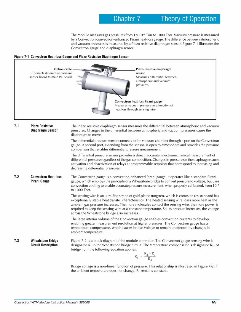
Convectron®ATM Module Instruction Manual - 385008 65
Chapter 7 Theory of Operation
The module measures gas pressures from 1 x 10⁻⁴ Torr to 1000 Torr. Vacuum pressure is measured by a Convectron convection-enhanced Pirani heat-loss gauge. The difference between atmospheric and vacuum pressures is measured by a Piezo resistive diaphragm sensor. Figure 7-1 illustrates the Convectron gauge and diaphragm sensor.
Figure 7-1 Convectron Heat-loss Gauge and Piezo Resistive Diaphragm Sensor
7.1 Piezo Resistive Diaphragm Sensor
The Piezo resistive diaphragm sensor measures the differential between atmospheric and vacuum pressures. Changes in the differential between atmospheric and vacuum pressures cause the diaphragm to move.
The differential pressure sensor connects to the vacuum chamber through a port on the Convectron gauge. A second port, extending from the sensor, is open to atmosphere and provides the pressure comparison that enables differential pressure measurement.
The differential pressure sensor provides a direct, accurate, electromechanical measurement of differential pressure regardless of the gas composition. Changes in pressure on the diaphragm cause activation and deactivation of relays at programmable setpoints that correspond to increasing and decreasing differential pressures.
7.2 Convectron Heat-loss Pirani Gauge
The Convectron gauge is a convection-enhanced Pirani gauge. It operates like a standard Pirani gauge, which employs the principle of a Wheatstone bridge to convert pressure to voltage, but uses convection cooling to enable accurate pressure measurement, when properly calibrated, from 10–4 to 1000 Torr.
The sensing wire is an ultra-fine strand of gold-plated tungsten, which is corrosion resistant and has exceptionally stable heat transfer characteristics. The heated sensing wire loses more heat as the ambient gas pressure increases. The more molecules contact the sensing wire, the more power is required to keep the sensing wire at a constant temperature. So, as pressure increases, the voltage across the Wheatstone bridge also increases.
The large interior volume of the Convectron gauge enables convection currents to develop, enabling greater measurement resolution at higher pressures. The Convectron gauge has a temperature compensator, which causes bridge voltage to remain unaffected by changes in ambient temperature.
7.3 Wheatstone Bridge Circuit Description
Figure 7-2 is a block diagram of the module controller. The Convectron gauge sensing wire is designated R1 in the Wheatstone bridge circuit. The temperature compensator is designated R2. At bridge null, the following equation applies:
Bridge voltage is a non-linear function of pressure. This relationship is illustrated in Figure 7-2. If the ambient temperature does not change, R1 remains constant.
Piezo resistive diaphragm sensorMeasures differential between atmospheric and vacuum pressures
Convectron heat-loss Pirani gaugeMeasures vacuum pressure as a function of heat loss through sensing wire
Ribbon cableConnects differential pressure
sensor board to main PC board
R1
R2 R3+R4
-------------------=
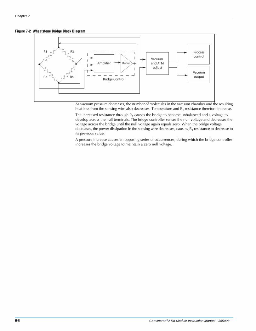
Chapter 7
66 Convectron®ATM Module Instruction Manual - 385008
Figure 7-2 Wheatstone Bridge Block Diagram
As vacuum pressure decreases, the number of molecules in the vacuum chamber and the resulting heat loss from the sensing wire also decreases. Temperature and R1 resistance therefore increase.
The increased resistance through R1 causes the bridge to become unbalanced and a voltage to develop across the null terminals. The bridge controller senses the null voltage and decreases the voltage across the bridge until the null voltage again equals zero. When the bridge voltage decreases, the power dissipation in the sensing wire decreases, causing R1 resistance to decrease to its previous value.
A pressure increase causes an opposing series of occurrences, during which the bridge controller increases the bridge voltage to maintain a zero null voltage.
Vacuum and ATM
adjust
Processcontrol
Vacuumoutput
Amplifier Buffer
Bridge Control
R1 R3
R4R2
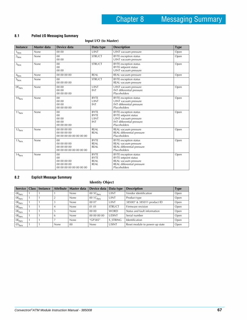
Convectron®ATM Module Instruction Manual - 385008 67
Chapter 8 Messaging Summary
8.1 Polled I/O Messaging Summary
8.2 Explicit Message Summary
Input I/O (to Master)
Instance Master data Device data Data type Description Type1hex None 00 00 UINT UINT vacuum pressure Open
2hex None 0000 00
STRUCT BYTE exception statusUINT vacuum pressure
Open
3hex None 000000 00
STRUCT BYTE exception statusBYTE setpoint statusUINT vacuum pressure
Open
4hex None 00 00 00 00 REAL REAL vacuum pressure Open
5hex None 0000 00 00 00
STRUCT BYTE exception statusREAL vacuum pressure
0Fhex None 00 0000 0000 00 00 00
UINTINT
UINT vacuum pressureINT differential pressurePlaceholders
Open
10hex None 0000 0000 0000 00 00 00
BYTEUINTINT
BYTE exception statusUINT vacuum pressureINT differential pressurePlaceholders
Open
11hex None 000000 0000 0000 00 00 00
BYTEBYTEUINTINT
BYTE exception statusBYTE setpoint statusUINT vacuum pressureINT differential pressurePlaceholders
Open
12hex None 00 00 00 0000 00 00 0000 00 00 00 00 00 00 00
REALREAL
REAL vacuum pressureREAL differential pressurePlaceholders
Open
13hex None 0000 00 00 0000 00 00 0000 00 00 00 00 00 00 00
BYTEREALREAL
BYTE exception statusREAL vacuum pressureREAL differential pressurePlaceholders
Open
14hex None 000000 00 00 0000 00 00 0000 00 00 00 00 00 00 00
BYTEBYTEREALREAL
BYTE exception statusBYTE setpoint statusREAL vacuum pressureREAL differential pressurePlaceholders
Open
Identity Object
Service Class Instance Attribute Master data Device data Data type Description Type0Ehex 1 1 1 None 00 5Chex UINT Vendor identification Open
0Ehex 1 1 2 None 00 1Chex UINT Product type Open
0Ehex 1 1 3 None 00 07 UINT 385007 & 385011 product ID Open
0Ehex 1 1 4 None 01 01 STRUCT Firmware revision Open
0Ehex 1 1 5 None 00 00 WORD Status and fault information Open
0Ehex 1 1 6 None 00 00 00 00 UDINT Serial number Open
0Ehex 1 1 7 None “GP385” S_STRING Identification Open
05hex 1 1 None 00 None USINT Reset module to power-up state Open
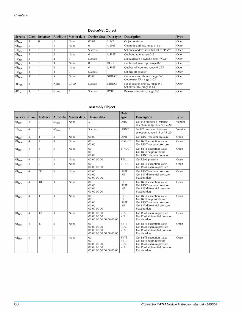
Chapter 8
68 Convectron®ATM Module Instruction Manual - 385008
DeviceNet Object
Service Class Instance Attribute Master data Device data Data type Description Type0Ehex 3 0 1 None 00 02 UINT Object revision Open
0Ehex 3 1 1 None 0 USINT Get node address, range 0–63 Open
10hex 3 1 1 0 Success Set node address if switch set to “PGM” Open
0Ehex 3 1 2 None 0 USINT Get baud rate, range 0–2 Open
10hex 3 1 2 0 Success Set baud rate if switch set to “PGM” Open
0Ehex 3 1 3 None 0 BOOL Get bus-off interrupt, range 0–1 Open
0Ehex 3 1 4 None 0 USINT Get bus-off counter, range 0–255 Open
10hex 3 1 4 0 Success Set bus-off counter Open
0Ehex 3 1 5 None 00 00 STRUCT Get allocation choice, range 0–3Get master ID, range 0–63
Open
4Bhex 3 1 None 03 00 Success STRUCT Set allocation choice, range 0–3Set master ID, range 0–63
Open
4Chex 3 1 None 3 Success BYTE Release allocation, range 0–3 Open
Assembly Object
Service Class Instance Attribute Master data Device dataData type Description Type
0Ehex 4 0 65hex None 5 USINT Get I/O produced instance selection, range 1–5 or 15–20
Vendor
10hex 4 0 65hex 5 Success USINT Set I/O produced instance selection, range 1–5 or 15–20
Vendor
0Ehex 4 1 3 None 00 00 UINT Get UINT vacuum pressure Open
0Ehex 4 2 3 None 0000 00
STRUCT Get BYTE exception statusGet UINT vacuum pressure
Open
0Ehex 4 3 3 None 000000 00
STRUCT Get BYTE exception statusGet BYTE setpoint statusGet UINT vacuum pressure
Open
0Ehex 4 4 3 None 00 00 00 00 REAL Get REAL pressure Open
0Ehex 4 5 3 None 0000 00 00 00
STRUCT Get BYTE exception statusGet REAL vacuum pressure
Open
0Ehex 4 0F 3 None 00 0000 0000 00 00 00
UINTINT
Get UINT vacuum pressureGet INT differential pressurePlaceholders
Open
0Ehex 4 10 3 None 0000 0000 0000 00 00 00
BYTE UINTINT
Get BYTE exception statusGet UINT vacuum pressureGet INT differential pressurePlaceholders
Open
0Ehex 4 11 3 None 000000 0000 0000 00 00 00
BYTEBYTEUINTINT
Get BYTE exception statusGet BYTE setpoint statusGet UINT vacuum pressureGet INT differential pressurePlaceholders
Open
0Ehex 4 12 3 None 00 00 00 0000 00 00 0000 00 00 00 00 00 00 00
REALREAL
Get REAL vacuum pressureGet REAL differential pressurePlaceholders
Open
0Ehex 4 13 3 None 0000 00 00 0000 00 00 0000 00 00 00 00 00 00 00
BYTEREALREAL
Get BYTE exception statusGet REAL vacuum pressureGet REAL differential pressurePlaceholders
Open
0Ehex 4 14 3 None 000000 00 00 0000 00 00 0000 00 00 00 00 00 00 00
BYTE BYTE REALREAL
Get BYTE exception statusGet BYTE setpoint statusGet REAL vacuum pressureGet REAL differential pressurePlaceholders
Open
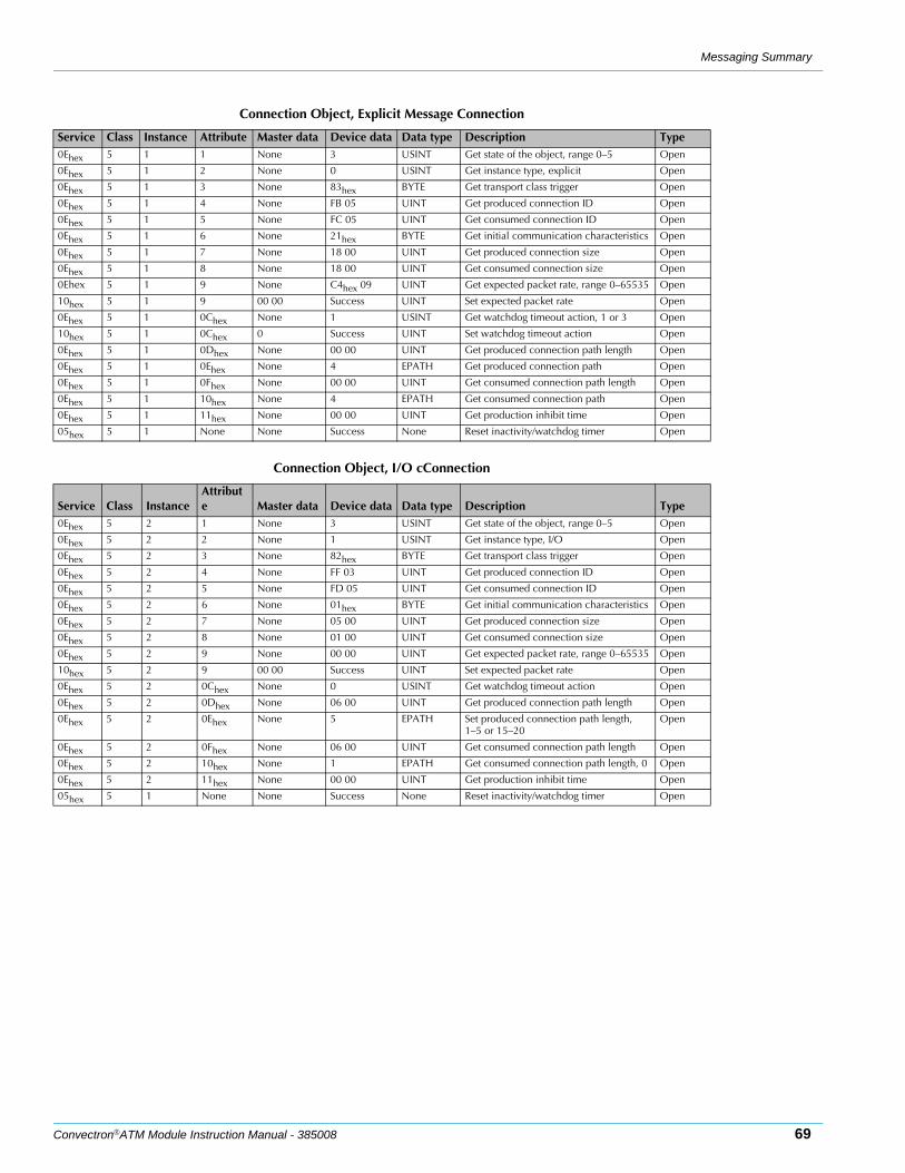
Messaging Summary
Convectron®ATM Module Instruction Manual - 385008 69
Connection Object, Explicit Message Connection
Service Class Instance Attribute Master data Device data Data type Description Type0Ehex 5 1 1 None 3 USINT Get state of the object, range 0–5 Open
0Ehex 5 1 2 None 0 USINT Get instance type, explicit Open
0Ehex 5 1 3 None 83hex BYTE Get transport class trigger Open
0Ehex 5 1 4 None FB 05 UINT Get produced connection ID Open
0Ehex 5 1 5 None FC 05 UINT Get consumed connection ID Open
0Ehex 5 1 6 None 21hex BYTE Get initial communication characteristics Open
0Ehex 5 1 7 None 18 00 UINT Get produced connection size Open
0Ehex 5 1 8 None 18 00 UINT Get consumed connection size Open
0Ehex 5 1 9 None C4hex 09 UINT Get expected packet rate, range 0–65535 Open
10hex 5 1 9 00 00 Success UINT Set expected packet rate Open
0Ehex 5 1 0Chex None 1 USINT Get watchdog timeout action, 1 or 3 Open
10hex 5 1 0Chex 0 Success UINT Set watchdog timeout action Open
0Ehex 5 1 0Dhex None 00 00 UINT Get produced connection path length Open
0Ehex 5 1 0Ehex None 4 EPATH Get produced connection path Open
0Ehex 5 1 0Fhex None 00 00 UINT Get consumed connection path length Open
0Ehex 5 1 10hex None 4 EPATH Get consumed connection path Open
0Ehex 5 1 11hex None 00 00 UINT Get production inhibit time Open
05hex 5 1 None None Success None Reset inactivity/watchdog timer Open
Connection Object, I/O cConnection
Service Class InstanceAttribute Master data Device data Data type Description Type
0Ehex 5 2 1 None 3 USINT Get state of the object, range 0–5 Open
0Ehex 5 2 2 None 1 USINT Get instance type, I/O Open
0Ehex 5 2 3 None 82hex BYTE Get transport class trigger Open
0Ehex 5 2 4 None FF 03 UINT Get produced connection ID Open
0Ehex 5 2 5 None FD 05 UINT Get consumed connection ID Open
0Ehex 5 2 6 None 01hex BYTE Get initial communication characteristics Open
0Ehex 5 2 7 None 05 00 UINT Get produced connection size Open
0Ehex 5 2 8 None 01 00 UINT Get consumed connection size Open
0Ehex 5 2 9 None 00 00 UINT Get expected packet rate, range 0–65535 Open
10hex 5 2 9 00 00 Success UINT Set expected packet rate Open
0Ehex 5 2 0Chex None 0 USINT Get watchdog timeout action Open
0Ehex 5 2 0Dhex None 06 00 UINT Get produced connection path length Open
0Ehex 5 2 0Ehex None 5 EPATH Set produced connection path length,1–5 or 15–20
Open
0Ehex 5 2 0Fhex None 06 00 UINT Get consumed connection path length Open
0Ehex 5 2 10hex None 1 EPATH Get consumed connection path length, 0 Open
0Ehex 5 2 11hex None 00 00 UINT Get production inhibit time Open
05hex 5 1 None None Success None Reset inactivity/watchdog timer Open
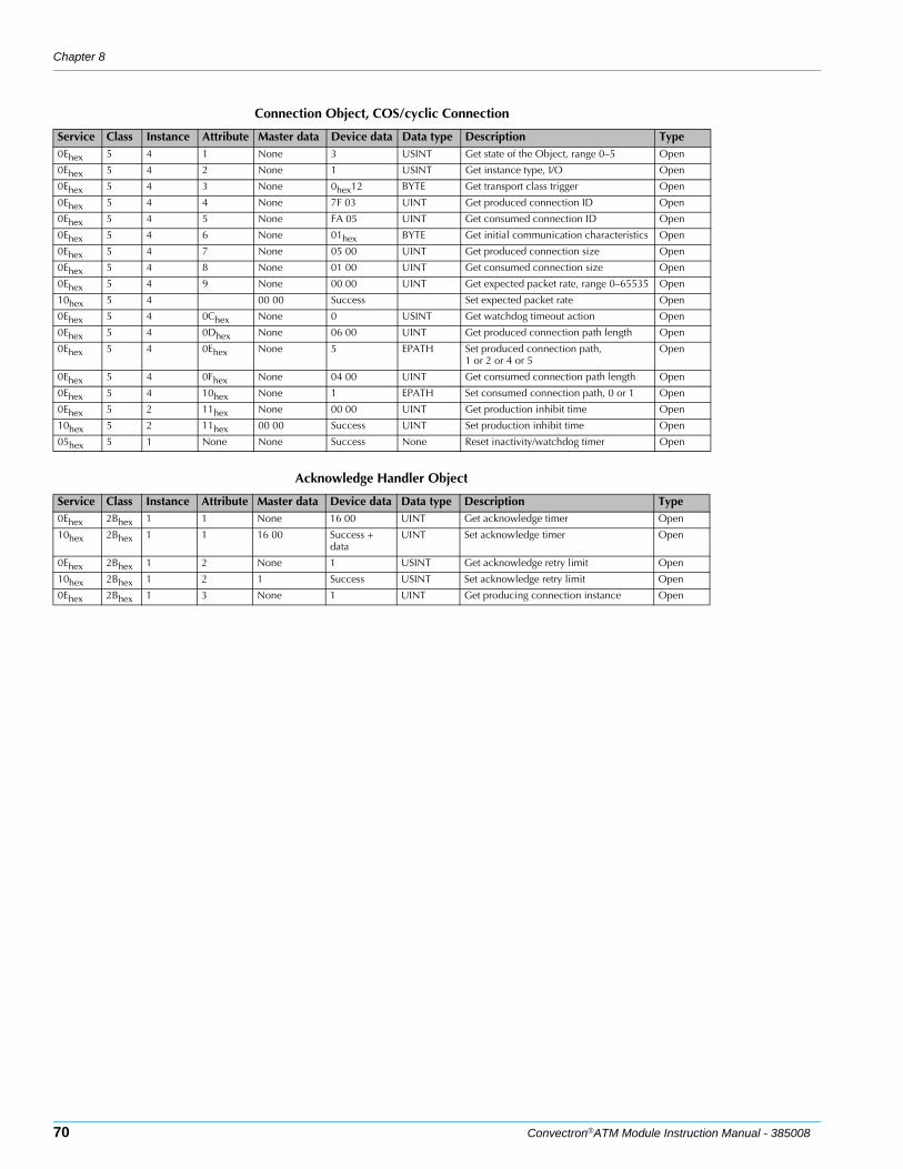
Chapter 8
70 Convectron®ATM Module Instruction Manual - 385008
Connection Object, COS/cyclic Connection
Service Class Instance Attribute Master data Device data Data type Description Type0Ehex 5 4 1 None 3 USINT Get state of the Object, range 0–5 Open
0Ehex 5 4 2 None 1 USINT Get instance type, I/O Open
0Ehex 5 4 3 None 0hex12 BYTE Get transport class trigger Open
0Ehex 5 4 4 None 7F 03 UINT Get produced connection ID Open
0Ehex 5 4 5 None FA 05 UINT Get consumed connection ID Open
0Ehex 5 4 6 None 01hex BYTE Get initial communication characteristics Open
0Ehex 5 4 7 None 05 00 UINT Get produced connection size Open
0Ehex 5 4 8 None 01 00 UINT Get consumed connection size Open
0Ehex 5 4 9 None 00 00 UINT Get expected packet rate, range 0–65535 Open
10hex 5 4 00 00 Success Set expected packet rate Open
0Ehex 5 4 0Chex None 0 USINT Get watchdog timeout action Open
0Ehex 5 4 0Dhex None 06 00 UINT Get produced connection path length Open
0Ehex 5 4 0Ehex None 5 EPATH Set produced connection path,1 or 2 or 4 or 5
Open
0Ehex 5 4 0Fhex None 04 00 UINT Get consumed connection path length Open
0Ehex 5 4 10hex None 1 EPATH Set consumed connection path, 0 or 1 Open
0Ehex 5 2 11hex None 00 00 UINT Get production inhibit time Open
10hex 5 2 11hex 00 00 Success UINT Set production inhibit time Open
05hex 5 1 None None Success None Reset inactivity/watchdog timer Open
Acknowledge Handler Object
Service Class Instance Attribute Master data Device data Data type Description Type0Ehex 2Bhex 1 1 None 16 00 UINT Get acknowledge timer Open
10hex 2Bhex 1 1 16 00 Success + data
UINT Set acknowledge timer Open
0Ehex 2Bhex 1 2 None 1 USINT Get acknowledge retry limit Open
10hex 2Bhex 1 2 1 Success USINT Set acknowledge retry limit Open
0Ehex 2Bhex 1 3 None 1 UINT Get producing connection instance Open
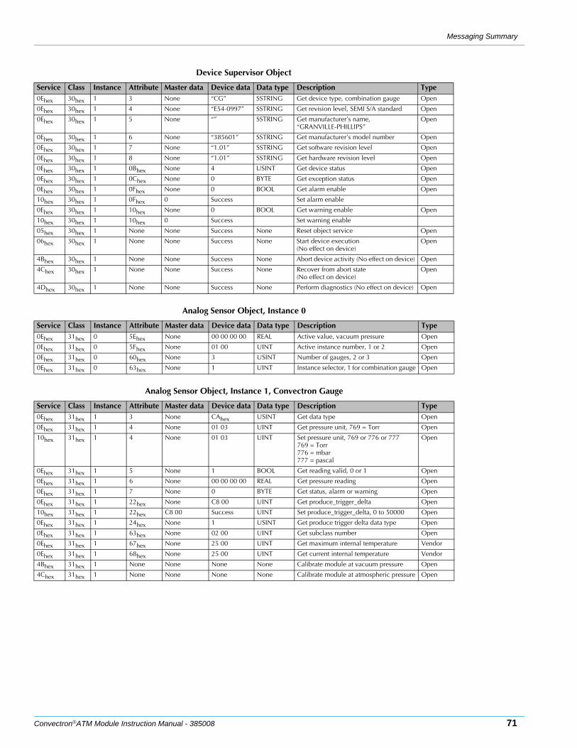
Messaging Summary
Convectron®ATM Module Instruction Manual - 385008 71
Device Supervisor Object
Service Class Instance Attribute Master data Device data Data type Description Type0Ehex 30hex 1 3 None “CG” SSTRING Get device type, combination gauge Open
0Ehex 30hex 1 4 None “E54-0997” SSTRING Get revision level, SEMI S/A standard Open
0Ehex 30hex 1 5 None “” SSTRING Get manufacturer’s name, “GRANVILLE-PHILLIPS”
Open
0Ehex 30hex 1 6 None “385601” SSTRING Get manufacturer’s model number Open
0Ehex 30hex 1 7 None “1.01” SSTRING Get software revision level Open
0Ehex 30hex 1 8 None “1.01” SSTRING Get hardware revision level Open
0Ehex 30hex 1 0Bhex None 4 USINT Get device status Open
0Ehex 30hex 1 0Chex None 0 BYTE Get exception status Open
0Ehex 30hex 1 0Fhex None 0 BOOL Get alarm enable Open
10hex 30hex 1 0Fhex 0 Success Set alarm enable
0Ehex 30hex 1 10hex None 0 BOOL Get warning enable Open
10hex 30hex 1 10hex 0 Success Set warning enable
05hex 30hex 1 None None Success None Reset object service Open
06hex 30hex 1 None None Success None Start device execution(No effect on device)
Open
4Bhex 30hex 1 None None Success None Abort device activity (No effect on device) Open
4Chex 30hex 1 None None Success None Recover from abort state(No effect on device)
Open
4Dhex 30hex 1 None None Success None Perform diagnostics (No effect on device) Open
Analog Sensor Object, Instance 0
Service Class Instance Attribute Master data Device data Data type Description Type0Ehex 31hex 0 5Ehex None 00 00 00 00 REAL Active value, vacuum pressure Open
0Ehex 31hex 0 5Fhex None 01 00 UINT Active instance number, 1 or 2 Open
0Ehex 31hex 0 60hex None 3 USINT Number of gauges, 2 or 3 Open
0Ehex 31hex 0 63hex None 1 UINT Instance selector, 1 for combination gauge Open
Analog Sensor Object, Instance 1, Convectron Gauge
Service Class Instance Attribute Master data Device data Data type Description Type0Ehex 31hex 1 3 None CAhex USINT Get data type Open
0Ehex 31hex 1 4 None 01 03 UINT Get pressure unit, 769 = Torr Open
10hex 31hex 1 4 None 01 03 UINT Set pressure unit, 769 or 776 or 777769 = Torr776 = mbar777 = pascal
Open
0Ehex 31hex 1 5 None 1 BOOL Get reading valid, 0 or 1 Open
0Ehex 31hex 1 6 None 00 00 00 00 REAL Get pressure reading Open
0Ehex 31hex 1 7 None 0 BYTE Get status, alarm or warning Open
0Ehex 31hex 1 22hex None C8 00 UINT Get produce_trigger_delta Open
10hex 31hex 1 22hex C8 00 Success UINT Set produce_trigger_delta, 0 to 50000 Open
0Ehex 31hex 1 24hex None 1 USINT Get produce trigger delta data type Open
0Ehex 31hex 1 63hex None 02 00 UINT Get subclass number Open
0Ehex 31hex 1 67hex None 25 00 UINT Get maximum internal temperature Vendor
0Ehex 31hex 1 68hex None 25 00 UINT Get current internal temperature Vendor
4Bhex 31hex 1 None None None None Calibrate module at vacuum pressure Open
4Chex 31hex 1 None None None None Calibrate module at atmospheric pressure Open
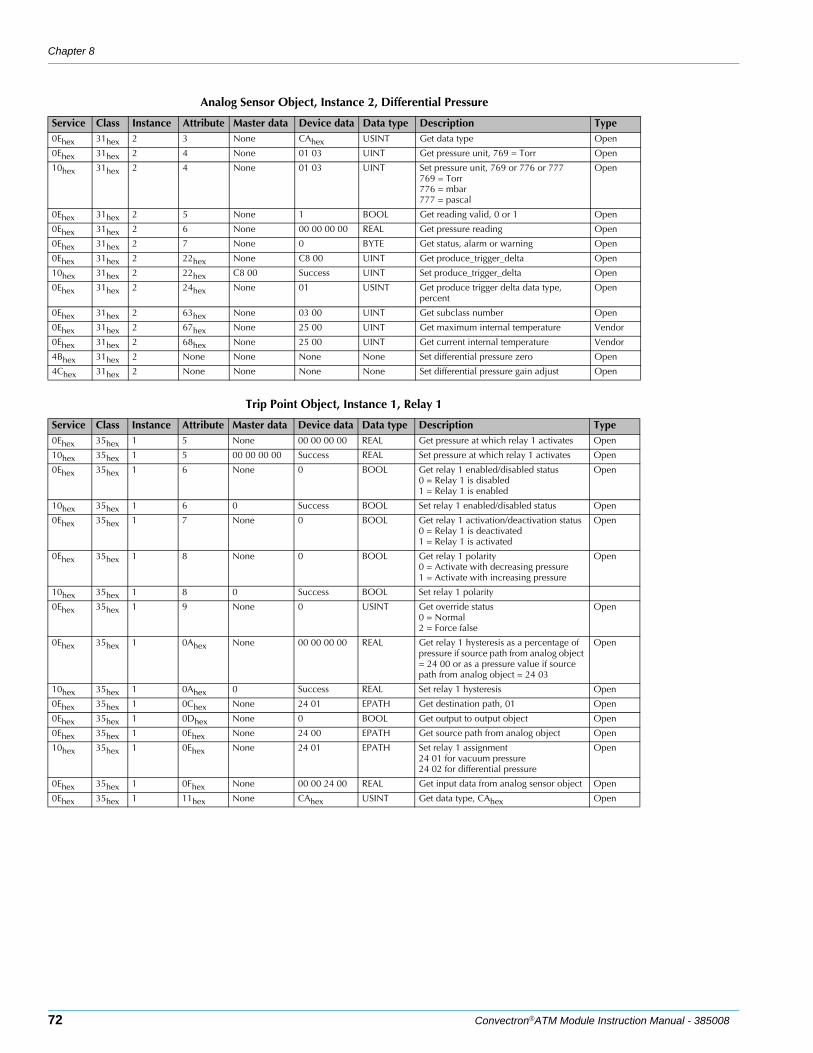
Chapter 8
72 Convectron®ATM Module Instruction Manual - 385008
Analog Sensor Object, Instance 2, Differential Pressure
Service Class Instance Attribute Master data Device data Data type Description Type0Ehex 31hex 2 3 None CAhex USINT Get data type Open
0Ehex 31hex 2 4 None 01 03 UINT Get pressure unit, 769 = Torr Open
10hex 31hex 2 4 None 01 03 UINT Set pressure unit, 769 or 776 or 777769 = Torr776 = mbar777 = pascal
Open
0Ehex 31hex 2 5 None 1 BOOL Get reading valid, 0 or 1 Open
0Ehex 31hex 2 6 None 00 00 00 00 REAL Get pressure reading Open
0Ehex 31hex 2 7 None 0 BYTE Get status, alarm or warning Open
0Ehex 31hex 2 22hex None C8 00 UINT Get produce_trigger_delta Open
10hex 31hex 2 22hex C8 00 Success UINT Set produce_trigger_delta Open
0Ehex 31hex 2 24hex None 01 USINT Get produce trigger delta data type, percent
Open
0Ehex 31hex 2 63hex None 03 00 UINT Get subclass number Open
0Ehex 31hex 2 67hex None 25 00 UINT Get maximum internal temperature Vendor
0Ehex 31hex 2 68hex None 25 00 UINT Get current internal temperature Vendor
4Bhex 31hex 2 None None None None Set differential pressure zero Open
4Chex 31hex 2 None None None None Set differential pressure gain adjust Open
Trip Point Object, Instance 1, Relay 1
Service Class Instance Attribute Master data Device data Data type Description Type0Ehex 35hex 1 5 None 00 00 00 00 REAL Get pressure at which relay 1 activates Open
10hex 35hex 1 5 00 00 00 00 Success REAL Set pressure at which relay 1 activates Open
0Ehex 35hex 1 6 None 0 BOOL Get relay 1 enabled/disabled status0 = Relay 1 is disabled1 = Relay 1 is enabled
Open
10hex 35hex 1 6 0 Success BOOL Set relay 1 enabled/disabled status Open
0Ehex 35hex 1 7 None 0 BOOL Get relay 1 activation/deactivation status0 = Relay 1 is deactivated1 = Relay 1 is activated
Open
0Ehex 35hex 1 8 None 0 BOOL Get relay 1 polarity0 = Activate with decreasing pressure1 = Activate with increasing pressure
Open
10hex 35hex 1 8 0 Success BOOL Set relay 1 polarity
0Ehex 35hex 1 9 None 0 USINT Get override status0 = Normal2 = Force false
Open
0Ehex 35hex 1 0Ahex None 00 00 00 00 REAL Get relay 1 hysteresis as a percentage of pressure if source path from analog object = 24 00 or as a pressure value if source path from analog object = 24 03
Open
10hex 35hex 1 0Ahex 0 Success REAL Set relay 1 hysteresis Open
0Ehex 35hex 1 0Chex None 24 01 EPATH Get destination path, 01 Open
0Ehex 35hex 1 0Dhex None 0 BOOL Get output to output object Open
0Ehex 35hex 1 0Ehex None 24 00 EPATH Get source path from analog object Open
10hex 35hex 1 0Ehex None 24 01 EPATH Set relay 1 assignment24 01 for vacuum pressure24 02 for differential pressure
Open
0Ehex 35hex 1 0Fhex None 00 00 24 00 REAL Get input data from analog sensor object Open
0Ehex 35hex 1 11hex None CAhex USINT Get data type, CAhex Open
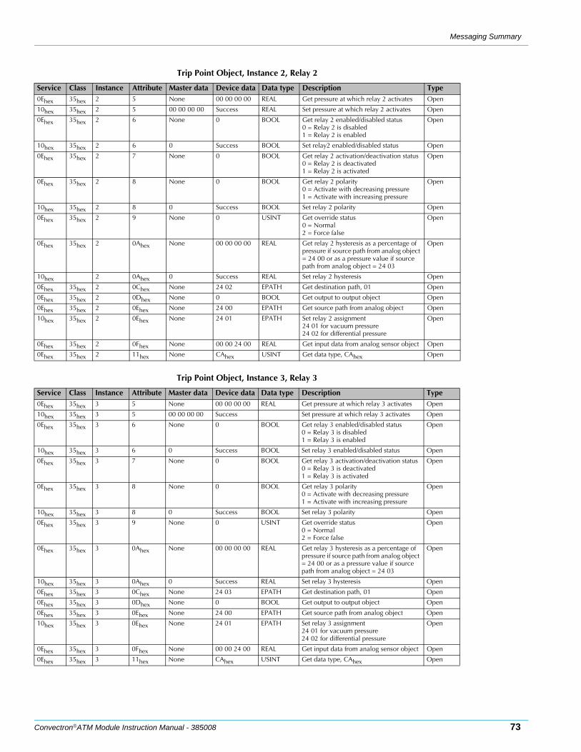
Messaging Summary
Convectron®ATM Module Instruction Manual - 385008 73
Trip Point Object, Instance 2, Relay 2
Service Class Instance Attribute Master data Device data Data type Description Type0Ehex 35hex 2 5 None 00 00 00 00 REAL Get pressure at which relay 2 activates Open
10hex 35hex 2 5 00 00 00 00 Success REAL Set pressure at which relay 2 activates Open
0Ehex 35hex 2 6 None 0 BOOL Get relay 2 enabled/disabled status0 = Relay 2 is disabled1 = Relay 2 is enabled
Open
10hex 35hex 2 6 0 Success BOOL Set relay2 enabled/disabled status Open
0Ehex 35hex 2 7 None 0 BOOL Get relay 2 activation/deactivation status0 = Relay 2 is deactivated1 = Relay 2 is activated
Open
0Ehex 35hex 2 8 None 0 BOOL Get relay 2 polarity0 = Activate with decreasing pressure1 = Activate with increasing pressure
Open
10hex 35hex 2 8 0 Success BOOL Set relay 2 polarity Open
0Ehex 35hex 2 9 None 0 USINT Get override status0 = Normal2 = Force false
Open
0Ehex 35hex 2 0Ahex None 00 00 00 00 REAL Get relay 2 hysteresis as a percentage of pressure if source path from analog object = 24 00 or as a pressure value if source path from analog object = 24 03
Open
10hex 2 0Ahex 0 Success REAL Set relay 2 hysteresis Open
0Ehex 35hex 2 0Chex None 24 02 EPATH Get destination path, 01 Open
0Ehex 35hex 2 0Dhex None 0 BOOL Get output to output object Open
0Ehex 35hex 2 0Ehex None 24 00 EPATH Get source path from analog object Open
10hex 35hex 2 0Ehex None 24 01 EPATH Set relay 2 assignment24 01 for vacuum pressure24 02 for differential pressure
Open
0Ehex 35hex 2 0Fhex None 00 00 24 00 REAL Get input data from analog sensor object Open
0Ehex 35hex 2 11hex None CAhex USINT Get data type, CAhex Open
Trip Point Object, Instance 3, Relay 3
Service Class Instance Attribute Master data Device data Data type Description Type0Ehex 35hex 3 5 None 00 00 00 00 REAL Get pressure at which relay 3 activates Open
10hex 35hex 3 5 00 00 00 00 Success Set pressure at which relay 3 activates Open
0Ehex 35hex 3 6 None 0 BOOL Get relay 3 enabled/disabled status0 = Relay 3 is disabled1 = Relay 3 is enabled
Open
10hex 35hex 3 6 0 Success BOOL Set relay 3 enabled/disabled status Open
0Ehex 35hex 3 7 None 0 BOOL Get relay 3 activation/deactivation status0 = Relay 3 is deactivated1 = Relay 3 is activated
Open
0Ehex 35hex 3 8 None 0 BOOL Get relay 3 polarity0 = Activate with decreasing pressure1 = Activate with increasing pressure
Open
10hex 35hex 3 8 0 Success BOOL Set relay 3 polarity Open
0Ehex 35hex 3 9 None 0 USINT Get override status0 = Normal2 = Force false
Open
0Ehex 35hex 3 0Ahex None 00 00 00 00 REAL Get relay 3 hysteresis as a percentage of pressure if source path from analog object = 24 00 or as a pressure value if source path from analog object = 24 03
Open
10hex 35hex 3 0Ahex 0 Success REAL Set relay 3 hysteresis Open
0Ehex 35hex 3 0Chex None 24 03 EPATH Get destination path, 01 Open
0Ehex 35hex 3 0Dhex None 0 BOOL Get output to output object Open
0Ehex 35hex 3 0Ehex None 24 00 EPATH Get source path from analog object Open
10hex 35hex 3 0Ehex None 24 01 EPATH Set relay 3 assignment24 01 for vacuum pressure24 02 for differential pressure
Open
0Ehex 35hex 3 0Fhex None 00 00 24 00 REAL Get input data from analog sensor object Open
0Ehex 35hex 3 11hex None CAhex USINT Get data type, CAhex Open
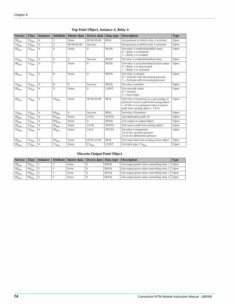
Chapter 8
74 Convectron®ATM Module Instruction Manual - 385008
Trip Point Object, Instance 4, Relay 4
Service Class Instance Attribute Master data Device data Data type Description Type0Ehex 35hex 4 5 None 00 00 00 00 REAL Get pressure at which relay 4 activates Open
10hex 35hex 4 5 00 00 00 00 Success Set pressure at which relay 4 activates Open
0Ehex 35hex 4 6 None 0 BOOL Get relay 4 enabled/disabled status0 = Relay 4 is disabled1 = Relay 4 is enabled
Open
10hex 35hex 4 6 0 Success BOOL Set relay 4 enabled/disabled status Open
0Ehex 35hex 4 7 None 0 BOOL Get relay 4 activation/deactivation status0 = Relay 4 is deactivated1 = Relay 4 is activated
Open
0Ehex 35hex 4 8 None 0 BOOL Get relay 4 polarity0 = Activate with decreasing pressure1 = Activate with increasing pressure
Open
10hex 35hex 4 8 0 Success BOOL Set relay 4 polarity Open
0Ehex 35hex 4 9 None 0 USINT Get override status0 = Normal2 = Force false
Open
0Ehex 35hex 4 0Ahex None 00 00 00 00 REAL Get relay 4 hysteresis as a percentage of pressure if source path from analog object = 24 00 or as a pressure value if source path from analog object = 24 03
Open
10hex 35hex 4 0Ahex 0 Success REAL Set relay 4 hysteresis Open
0Ehex 35hex 4 0Chex None 24 03 EPATH Get destination path, 01 Open
0Ehex 35hex 4 0Dhex None 0 BOOL Get output to output object Open
0Ehex 35hex 4 0Ehex None 24 00 EPATH Get source path from analog object Open
10hex 35hex 4 0Ehex None 24 01 EPATH Set relay 4 assignment24 01 for vacuum pressure24 02 for differential pressure
Open
0Ehex 35hex 4 0Fhex None 00 00 24 00 REAL Get input data from analog sensor object Open
0Ehex 35hex 4 11hex None CAhex USINT Get data type, CAhex Open
Discrete Output Point Object
Service Class Instance Attribute Master data Device data Data type Description Type0Ehex 09hex 1 3 None 0 BOOL Get output point value controlling relay 1 Open
0Ehex 09hex 2 3 None 0 BOOL Get output point value controlling relay 2 Open
0Ehex 09hex 3 3 None 0 BOOL Get output point value controlling relay 3 Open
0Ehex 09hex 4 3 None 0 BOOL Get output point value controlling relay 4 Open
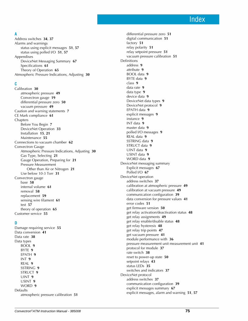
Convectron®ATM Instruction Manual - 385008 75
Index
AAddress switches 34, 37Alarms and warnings
status using explicit messages 51, 57status using polled I/O 51, 57
AppendixesDeviceNet Messaging Summary 67Specifications 61Theory of Operation 65
Atmospheric Pressure Indications, Adjusting 30
CCalibration 30
atmospheric pressure 49Convectron gauge 19differential pressure zero 50vacuum pressure 49
Caution and warning statements 7CE Mark compliance 61Chapters
Before You Begin 7DeviceNet Operation 33Installation 15, 21Maintenance 55
Connections to vacuum chamber 62Convectron Gauge
Atmospheric Pressure Indications, Adjusting 30Gas Type, Selecting 21Gauge Operation, Preparing for 21Pressure Measurement
Other than Air or Nitrogen 21Use below 10-3 Torr 31
Convectron gaugebase 58internal volume 61removal 58replacement 59sensing wire filament 61test 57theory of operation 65
Customer service 55
DDamage requiring service 55Data conversion 41Data rate 38Data types
BOOL 9BYTE 9EPATH 9INT 9REAL 9SSTRING 9STRUCT 9UINT 9USINT 9WORD 9
Defaultsatmospheric pressure calibration 51
differential pressure zero 51digital communication 51factory 51relay polarity 51relay setpoint pressure 51vacuum pressure calibration 51
Definitionsaddress 9attribute 9BOOL data 9BYTE data 9class 9data rate 9data type 9device data 9DeviceNet data types 9DeviceNet protocol 9EPATH data 9explicit messages 9instance 9INT data 9master data 9polled I/O messages 9REAL data 9SSTRING data 9STRUCT data 9UINT data 9USINT data 9WORD data 9
DeviceNet messaging summaryExplicit messages 67Polled I/O 67
DeviceNet operationaddress switches 37calibration at atmospheric pressure 49calibration at vacuum pressure 49communication configuration 39data conversion for pressure values 41error codes 51get firmware version 50get relay activation/deactivation status 48get relay assignments 49get relay enable/disable status 48get relay hysteresis 48get relay trip points 47get vacuum pressure 41module performance with 36pressure measurement unit measurement unit 41protocol for module 37rate switch 38reset to power-up state 50setpoint relays 43status LEDs 35switches and indicators 37
DeviceNet protocoladdress switches 37communication configuration 39explicit messages summary 67explicit messages, alarm and warning 51, 57
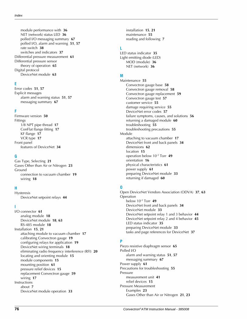
Index
76 Convectron®ATM Instruction Manual - 385008
module performance with 36NET (network) status LED 36polled I/O messaging summary 67polled I/O, alarm and warning 51, 57rate switch 38switches and indicators 37
Differential pressure measurement 61Differential pressure sensor
theory of operation 65Digital protocol
DeviceNet module 63
EError codes 51, 57Explicit messages
alarm and warning status 51, 57messaging summary 67
FFirmware version 50Fittings
1/8 NPT pipe thread 17ConFlat flange fitting 17KF flange 17VCR type 17
Front panelfeatures of DeviceNet 34
GGas Type, Selecting 21Gases Other than Air or Nitrogen 23Ground
connection to vacuum chamber 19wiring 18
HHysteresis
DeviceNet setpoint relays 44
II/O connector 61
analog module 18DeviceNet module 18, 63RS-485 module 18
Installation 15, 21attaching module to vacuum chamber 17calibrating Convectron gauge 19configuring relays for application 19DeviceNet wiring terminals 18eliminating radio frequency interference (RFI) 20locating and orienting module 15module components 15mounting position 61pressure relief devices 15replacement Convectron gauge 59wiring 17
Instructionsabout 7DeviceNet module operation 33
installation 15, 21maintenance 55reading and following 7
LLED status indicator 35Light emitting diode (LED)
MOD (module) 36NET (network) 36
MMaintenance 55
Convectron gauge base 58Convectron gauge removal 58Convectron gauge replacement 59Convectron gauge test 57customer service 55damage requiring service 55DeviceNet error codes 57failure symptoms, causes, and solutions 56returning a damaged module 60troubleshooting 55troubleshooting precautions 55
Moduleattaching to vacuum chamber 17DeviceNet front and back panels 34dimensions 62location 15operation below 10-3 Torr 49orientation 16physical characteristics 61power supply 61preparing DeviceNet module 33returning if damaged 60
OOpen DeviceNet Vendors Association (ODVA) 37, 63Operation
below 10-3 Torr 49DeviceNet front and back panels 34DeviceNet module 33DeviceNet setpoint relay 1 and 3 behavior 44DeviceNet setpoint relay 2 and 4 behavior 45LED status indicator 35preparing DeviceNet module 33tasks and page references for DeviceNet 37
PPiezo resistive diaphragm sensor 65Polled I/O
alarm and warning status 51, 57messaging summary 67
Power supply 61Precautions for troubleshooting 55Pressure
measurement unit 41relief devices 15
Pressure MeasurementExamples 23Gases Other than Air or Nitrogen 21, 23
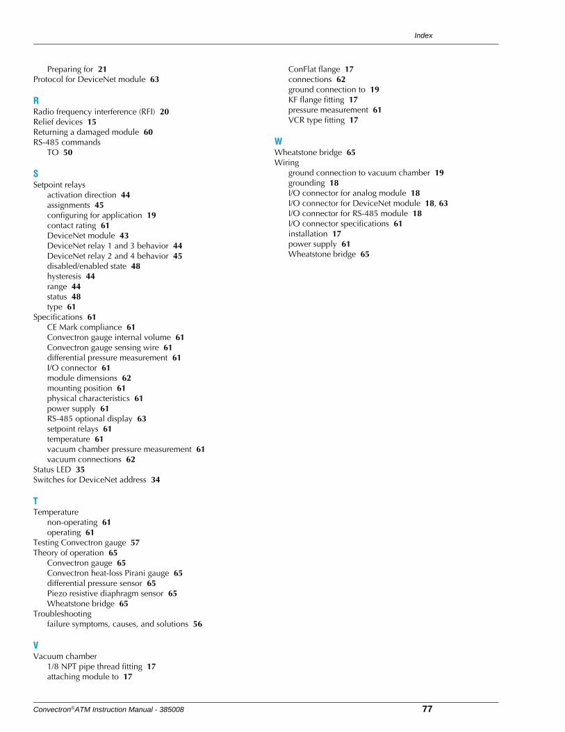
Index
Convectron®ATM Instruction Manual - 385008 77
Preparing for 21Protocol for DeviceNet module 63
RRadio frequency interference (RFI) 20Relief devices 15Returning a damaged module 60RS-485 commands
TO 50
SSetpoint relays
activation direction 44assignments 45configuring for application 19contact rating 61DeviceNet module 43DeviceNet relay 1 and 3 behavior 44DeviceNet relay 2 and 4 behavior 45disabled/enabled state 48hysteresis 44range 44status 48type 61
Specifications 61CE Mark compliance 61Convectron gauge internal volume 61Convectron gauge sensing wire 61differential pressure measurement 61I/O connector 61module dimensions 62mounting position 61physical characteristics 61power supply 61RS-485 optional display 63setpoint relays 61temperature 61vacuum chamber pressure measurement 61vacuum connections 62
Status LED 35Switches for DeviceNet address 34
TTemperature
non-operating 61operating 61
Testing Convectron gauge 57Theory of operation 65
Convectron gauge 65Convectron heat-loss Pirani gauge 65differential pressure sensor 65Piezo resistive diaphragm sensor 65Wheatstone bridge 65
Troubleshootingfailure symptoms, causes, and solutions 56
VVacuum chamber
1/8 NPT pipe thread fitting 17attaching module to 17
ConFlat flange 17connections 62ground connection to 19KF flange fitting 17pressure measurement 61VCR type fitting 17
WWheatstone bridge 65Wiring
ground connection to vacuum chamber 19grounding 18I/O connector for analog module 18I/O connector for DeviceNet module 18, 63I/O connector for RS-485 module 18I/O connector specifications 61installation 17power supply 61Wheatstone bridge 65

Index
78 Convectron®ATM Instruction Manual - 385008

.
Granville-Phillips® Series 385 Convectron® ATM Vacuum Gauge Module with DeviceNetTM
Instruction manual part number 385008
Revision G - July 2017
Instruction Manual
Series 385
Customer Service / Technical Support:
MKS Pressure and Vacuum Measurement SolutionsMKS Instruments, Inc., Granville-Phillips® Division6450 Dry Creek ParkwayLongmont, Colorado 80503 USATel: 303-652-4400Fax: 303-652-2844Email: [email protected]
MKS Corporate HeadquartersMKS Instruments, Inc.2 Tech Drive, Suite 201Andover, MA 01810 USATel: 978-645-5500Fax: 978-557-5100Email: [email protected]