Embed Size (px)
Citation preview

1
Gotharman’s Little deFormer 3
Granular Workstation
Update Manual 8.15
2
In this manual:
-New shortcuts has been added for selecting presets, copying morph layer and more. Page 5
-Song mode is now fully functional. Page 9
-Copy/paste system is now fully functional. Page 28
-Synth parameters Randomizer is now fully functional. Page 31
-Compressor, Expandor, Filters and Filters2 has been added to the Insert Effects. Page 33
-Parameters “Snap” mode has now been added. Page 43
-The Granular modulators are now working. Page 45
-Each part can now be set in either polyphonic mode, or mono to a specific voice mode. Page 47
-Any of the 8 audio busses can now be inserted in the output effects feedback loops. Page 48
-A Sample Loop Smoothing function has been added. Page 49
-Chop modes on the Sample Edit Chop page, can now be by Peak, by Wave or a sampling can be
chopped in 2 to 64 equal portions. Page 50
-Sample chop playback in the synth part samplers can now be switched off. Page 51
-Sequencer step recording mode has been added. Page 52
-Controller tracks realtime recording is now possible. Page 55
-Sequencer tracks “Double” touch button added. Page 58
-Sub position track added to the sequencer note tracks for micro timing. Page 59
-Controller tracks can now handle Pitch Bend, both internally and externally. Page 60
-Controller tracks can now be set to send MIDI CC’s either internally or externally through MIDI
out. Page 61

3
-Controller tracks program change messages. Page 62
-Level adjustment, VU-meters and part envelopes added to the audio busses. Page 63
-VU-meters added to the input BUS select page. Page 69
-SPAZEboard 2 compability added. Page 70
-Sample Record Monitor can now be set to Off, On or Rec. Page 82
-1v/oct and 1.2v/oct quantizing has been added to the controller tracks. Page 83
-A “PANIC” function has now been added. Page 84
-Sequencer Record state and tempo are now shown on the main preset select page. Page 85
-USB: Wav samples preview. Page 86
-USB: Import sample bank can now be selected on the USB Import page. Page 87
-Modulation part can now be selected for each of the CV outputs. Page 88
-Part Trigger has been added as a modulation source. Page 89
-MIDI CC 17 to 61 has been added as modulation sources. Page 90
-3 extra Random Generators has been added as modulation sources. Page 91
-Preset Preview function is now working. Page 92
-When clearing a sequence or a sequencer track, the tracks are now completely cleared. Page 93
-Escape touch button added on the Sequencer Main page. Page 94
-LFO’s key-trigger can now be set to part 1 to 16. Page 95
-Update your LD3. See how on page 96

4
Bug fixes:
-Effects LINK function is now working.
-When realtime recording a note track in poly mode, steps 34 to 64 would not be recorded. This
has now been fixed.
-When realtime recording a note track in mono mode, the position track were not altered. So if
you previously recorded the same track in poly mode, where the positions is set for each step,
these positions would still be there, when re-recording the track in mono mode, regardless of
when the notes were played. This has now been fixed.
-When controlling a part using pitch bend or other realtime controllers, voices that were not
assigned to the part being controlled, would also be affected. This has now been fixed, so only the
part being controlled are affected by realtime controllers.
-When morphing between 2 sequences, the position track would not morph correctly. This has
now been fixed.
-Sometimes, when controlling a part from the internal sequencer and an external MIDI keyboard
at the same time, notes would hang. This has now been fixed.
-The percentage of Bank A used sampled memory did not show correctly. This has now been fixed.
-Step 65 to 128 on the controller tracks were not randomized correctly, when randomized. This
has now been fixed.
-USB: Export sample number is now shown correctly.
-In some places, the left and right audio inputs and outputs, were named “1” and “2”. These
names has now been changed to “L” and “R” (hopefully) everywhere.
-Chop points for use with Reload are now exported.

5
New short cuts:
Copy Morph Layer A to Layer B
Push and release the Func/Mute button, so that it lights up, to enter the function buttons. Now
push and release step button 13 (Copy), so that this also lights up. Instructions for copy and panic
will now be shown on the screen. Push and release the Morph Set button. Morph layer A synth
parts and sequencer parameters has now been copied to morph layer B. If you turn the Morph
knobs, you should now hear the same sound/sequence, no matter what position the knobs are in.
Selecting the next preset
Push and hold the Steps/Part button while pressing the Start/Stop button. LD3 will now select the
next preset. If the sequencer is playing back, the Start/Stop LED will now start to flash, and the
text “NEXT:” will show right above the new presets name, awaiting track 1 to reach its start/end
step. As soon as this happens, LD3 will switch to the newly selected preset, the Start/Stop LED will
stop flashing, and “NEXT:” will dissapear.
If the sequencer is not playing back, LD3 will immediately switch to the new preset.

6
Selecting the previous preset
Push and hold the Steps/Part button while pressing the Morph/Set button. LD3 will now select
the previous preset. If the sequencer is playing back, the Start/Stop LED will now start to flash,
and the text “NEXT:” will show right above the new presets name, awaiting track 1 to reach its
start/end step. As soon as this happens, LD3 will switch to the newly selected preset, the
Start/Stop LED will stop flashing, and “NEXT:” will dissapear.
If the sequencer is not playing back, LD3 will immediately switch to the new preset.

7
Selecting Presets using the step buttons
Push and hold the Steps/Part button while pressing the Func/Mute button. Now both of these
buttons will light up.
It is now possible to select the 64 presets in the currently selected preset bank, using the step
buttons. Step button 1 to 8 selects the lower digit of the preset number, and step button 9-16
selects the higher digit.
When pushing the same button combination again, the Steps/Part button will still light up, while
the Func/Mute button will start to flash.
It is now possible to select preset bank A to P, using step buttons 1 to 16.
Pushing the same button combination yet another time, will exit from the preset select mode.

8
Preset Reload / Advance Song realtime record step
Push and hold the Morph Set button, while pressing the Start/Stop button, to reload the currently
selected preset.
While realtime recording a song, reloading the preset, will cause the song recorder to advance to
the next song step. This is useful for recording track mutes of the same preset into the song.
Panic
Push and release the Func/Mute button, so that it lights up, to enter the function buttons. Now
push and release step button 13 (Copy), so that this also lights up. Instructions for copy and panic
will now be shown on the screen. Push and release step button 16 (Exit).
Now all notes, both internally and on any MIDI devices connected to the LD3 MIDI out, will be
shutted off.

9
Song Mode
It is possible to arrange chained playback of Presets in 1024 Song locations. Each Song can have up to 128 steps. For each Song step a Preset can be selected, it can be set how many times track one of the preset should play back, until it advances to the next song step, and tracks can be muted/unmuted. If the last step of the Song is set to ”End”, playback will stop, when the Song has played back the last preset. If the last step of a Song is set to ”Loop”, it will jump back to step 1, and continue playback, after the last preset has played. Songs can be realtime recorded, simply by hitting the ”Rec” button on the song main page, then the ”Play” button, and then play back the presets that you want in your song. Songs can also be recorded/edited by putting the Preset numbers and number of times to play back, into a list. Any presets can be used in any songs. In song mode you still have access to edit all preset synth parameters, in the currently playing preset, but you can’t immediately save any changes you make, since in song mode, you can only save the song.

10
Accessing Song Mode
If you would like to make a new song from scratch, it can be a good idea to select the preset you would like to have on the first song step, from the preset select page, before you enters song mode. This is not something you have to do, I have just experienced, when testing this, that it makes things a bit easier. When you select a non-recorded empty song, the last selected preset will automatically be placed on song step 1.
From the Preset Select page, hit the EDIT field.

11
On the navigation bar at the top of the screen, touch MOR...

12
In the far right row, you will find the text PRS. Please touch this, after making sure, that the sequencer is stopped.

13
Now PRS turns into SONG, and LD3 are in song mode. If you would like to go back to preset mode, just touch SONG.

14
The Song Edit Page To enter the Song Edit page, just touch SEQ on the navigation bar at the top of the More… page:
On the Song Edit page, you have an overview of the programmed song steps, and the possibility of editing these. By touching any of the song steps, you can select this step for editing. The selected step is shown, boxed in blue. The little brown square between the step number and the preset name, is showing what song step is currently being played back. For each song step, the song step number is shown, the preset number and name, and the number of times track 1 will play back (under the X). To edit a song step, turn edit knob 1 to select <End>, preset bank A to P, or <Loop>. <End> will make song playback stop, when it reaches that step, <Loop> will make it jump back to song step 1, and start all over again. Turn edit knob 2 to select the preset number, and edit knob 3 to select the number of times, you want track 1 to play back, for that step. Push and hold the Func/Mute button, to mute/unmute tracks on the selected song step, via the step buttons. Only tracks that are unmuted in the preset itself, can be muted by the song sequencer.

15
8 song steps are shown at a time. Touch the arrows to select the previous or next 8 song steps. The total number of song steps is 128.
Touch EXIT to exit from the Song Edit page, and touch REC to start song realtime recording. This will be explained very soon.

16
The Song Select Page
When you, in song mode, exit from the Edit Groups pages, you will exit to the Song Select page, instead of the Preset Select page. This reads out ”Song” just above the song number and name, instead of the ”Preset”, to make sure that you know where you are. On the top of the Song Select page, you might have noticed, that the sequencer position ruler has gained an extra digit. The first digit of this now shows the song step number, that is currently being played back. The 2 other digits is still showing the bar and the beat of the preset, that is currently playing back. Other changes to this, compared to the Preset Select page, are that the field in the upper left corner, that was used to select preset with, now has been renamed to SONG, and is used to select song with. It is only possible to select another song, while the sequencer is stopped. Besides from these changes, everything is the same as in preset mode. You can still edit the synth parameters of the currently playing preset.

17
Selecting a song: Make sure that the sequencer is stopped.
Touch the “SONG” field. A list of 5 songs near the currently selected song, will now appear:
Touch “PREV” or “NEXT” to view the previous or next 5 songs, and finally touch the song name of
the song you would like to select. 1024 songs can be selected, from A01 to P64.
LD3 will now jump back to the main Song Select screen, and show the name of the newly selected
song.
When LD3 is turned off, it will remember which song was selected, and start up with this, when
turned on again. It will also remember if it was in preset or song mode, and start up in the same
mode.
18
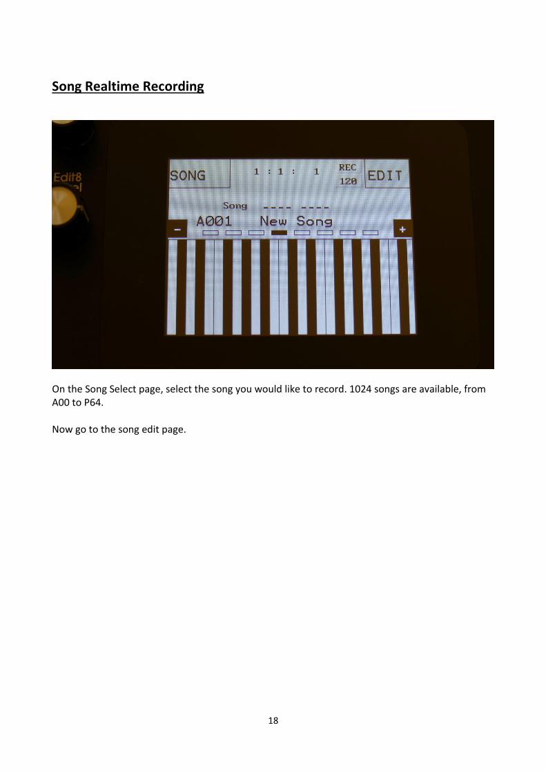
Song Realtime Recording
On the Song Select page, select the song you would like to record. 1024 songs are available, from A00 to P64. Now go to the song edit page.

19
Make sure that the sequencer is stopped, and push the “REC” button, so it turns red. Now exit to the Preset/Song select screen.

20
LD3 will now show the Preset select page. The REC indicator on the preset select page, has now turned red, indicating that LD3 is in recording mode. Song realtime recording can also be switched on or off, by touching the REC indicator. If you selected an empty song, the last preset you selected, before you jumped to song mode, will be shown. If you selected a song that was already recorded, the preset on the selected step of this song will be shown. Now, if the shown preset are the preset you would like to have on step 1 of your song, you can proceed recording your song, by pressing the Start/Stop button. If you would like another preset on step 1 of your song, please select this, using the preset select field, and then push the Start/Stop button, to start the recording of the song. The preset you selected will now start to play back. From here you can now select other presets, at the time you want these to play back in your song. Preset changes will only be registrered and recorded, when track 1 of the currently playing preset reaches its end and starts over. When the changes has been registrered, the song step number in the position ruler will increment by one. While any preset is playing back, it is possible to mute/unmute the sequence tracks. Push and hold the Func/Mute button, and switch tracks on or off, using the step buttons.

21
To advance to the next song step, to have other tracks of the same preset muted/unmuted, simply reload the preset, by pushing and holding the Morph Set button, while pressing the Start/Stop button. When you are done changing presets, and you think that your song is ready, hit the Start/Stop button to stop song recording. Go back to the song edit page, and touch the REC button, so it turns grey again, to exit from song realtime recording, or simply exit to the preset/song select page, and touch the REC indicator.
To listen to the song you have just created, just hit the Start/Stop button. If there are anything you would like to edit, go to the Song Edit page, as described earlier. If you would like to keep your work, you should save your new song.

22
Save Song
LD3 songs are not saved within the presets, so they must be saved separately. To do so, when in song mode, from the song select page, touch the EDIT field to enter the Synth parts page:
Touch SAV.

23
You should now enter this page:
Touch the song location that you would like to save your new song to. If it is not shown, touch PREV and NEXT to reach it. Song number and name is shown for songs that are already saved. If you save your new song on such a location, the old song will be overwritten. On song locations, where a song has not yet been saved, the name will be shown as ”<empty>”.

24
Turn edit knob 1 to 8 to select the first 8 letters of the name for your new song.
Touch NEXT when you are done.
25
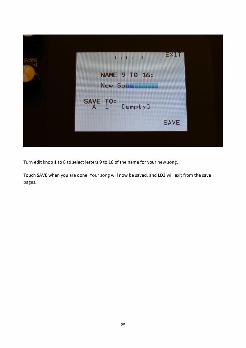
Turn edit knob 1 to 8 to select letters 9 to 16 of the name for your new song.
Touch SAVE when you are done. Your song will now be saved, and LD3 will exit from the save
pages.

26
Initializing a Song If you would just like to start all over with an empty song, it is possible to initialize it. To do so, in song mode, access the MOR page:
From here, hit INIT.

27
LD3 will now ask you to confirm.
Press ”Yes” to initialize the currently selected song and return to the previous page, or press ”No” just to exit, without initializing. Please notice, that when initializing a song, this is only done in LD3’s temporary song RAM, NOT on the FLASH memory, so if you did this by mistake, or you regretted doing it, you can always recall the song, by selecting another song, and select this again. Then nothing will be lost. It is not until you save the song, that permanent changes is done.

28
Copy/Paste
On LD3 it is possible to copy morph layer A, B or the parameter setting at the position of the
Morph knob. It is possible to copy one or two layers of the whole preset, or only a section of the
preset, like a synth part, the settings of a filter, a sequencer track, and much more.
Whatever is held in the copy buffer can then be pasted to another preset or another section.
If you, for instance, copy a whole preset, or a whole part, and then goes to a specific filter page to
just paste the filter settings, only the settings in the copy buffer from the same part number will
be pasted. If you would like to copy, for instance, the filter settings from part 3 in one preset, to
part 7 in another preset, you will have to go to the specific part filter page, to copy, and then go to
the destination filter page to paste.
To copy anything, first go to the page, that will make LD3 copy the desired settings. Possibilities
are:
-Preset select page: LD3 will copy one or two layers of the whole preset.
-Synth part page: LD3 will copy one or two layers of the selected part. Included in this are the
oscillator, the digital filters, VCA and Envelope settings.
-BUS page: LD3 will copy all the BUS settings.
-Oscillator page: LD3 will copy one or two layers of the oscillator settings, of the currently selected
part.
-Digital Filter page: LD3 will copy one or two layers of the Digital filter settings, of the currently
selected part.
-VCA page: LD3 will copy one or two layers of the VCA settings, of the currently selected part.
-Envelope page: LD3 will copy one or two layers of the Envelope settings, of the currently selected
part.
-VCF (Filterboard) page: LD3 will copy one or two layers of the VCF settings, of the currently
selected VCF.
-LFO page: LD3 will copy one or two layers of the LFO settings, of the currently selected LFO.
-EFX page: LD3 will copy one or two layers of the EFX settings, of the currently selected EFX.
-RNDM, TRIG and ZONE pages: Nothing will be copied.
-Sequencer overview page: One or two layers of all the sequencer tracks will be copied.
-Sequencer track page: One or two layers of the currently selected sequencer track will be copied.

29
When you are located at the right page, push and release the Func/Mute button, so that it lights
up, to enter the function buttons. Now hit step button 13 (Copy).
The display will now show some instructions:
It will tell you how to copy layer A to layer B, and right below this, it will tell you, what it will copy.
In the example, the copy function was entered from the preset select page, and LD3 tells you, that
it will copy the whole preset.
If you had entered the copy page from a filter page, it would have said “COPY FILTER pt 1” instead.
Now select/deselect the desired layers, by touching the “A”, “B” and “Morph” touch buttons. If a
layer button is black, it means that this layer will be copied, if it is grey, the layer will not be
copied. It is only possible to copy either layer B or the morphed layer. It is not possible to copy
both of these at the same time. Layer A can be switched on or off independently of the B/Morph

30
selection. If 2 layers are copied, LD3 will also paste to 2 layers. If only one layer is copied, LD3 will
paste to the layer selected by the Morph Set button.
To copy, hit step button 13 (Copy) again.
Now, when the function buttons are active (the Func/Mute button lights up), every time you enter
a page, where the copy buffer holds something, that can be pasted, step button 14 (Paste) will
light up.
To paste something, navigate to the desired page, where you would like to paste the settings.
Make sure that step button 14 (Paste) lights up. Hit step button 14 (Paste). Your settings has now
been pasted.

31
Synth Parameters Randomizer
If you should ever need some new inspiration for sounds, or if you just want to surprise yourself
with some sounds that you never even imagined, the LD3 parameter randomizer might be exactly
what you need.
To enter this, from the synth parts main page, touch RNDM.
32
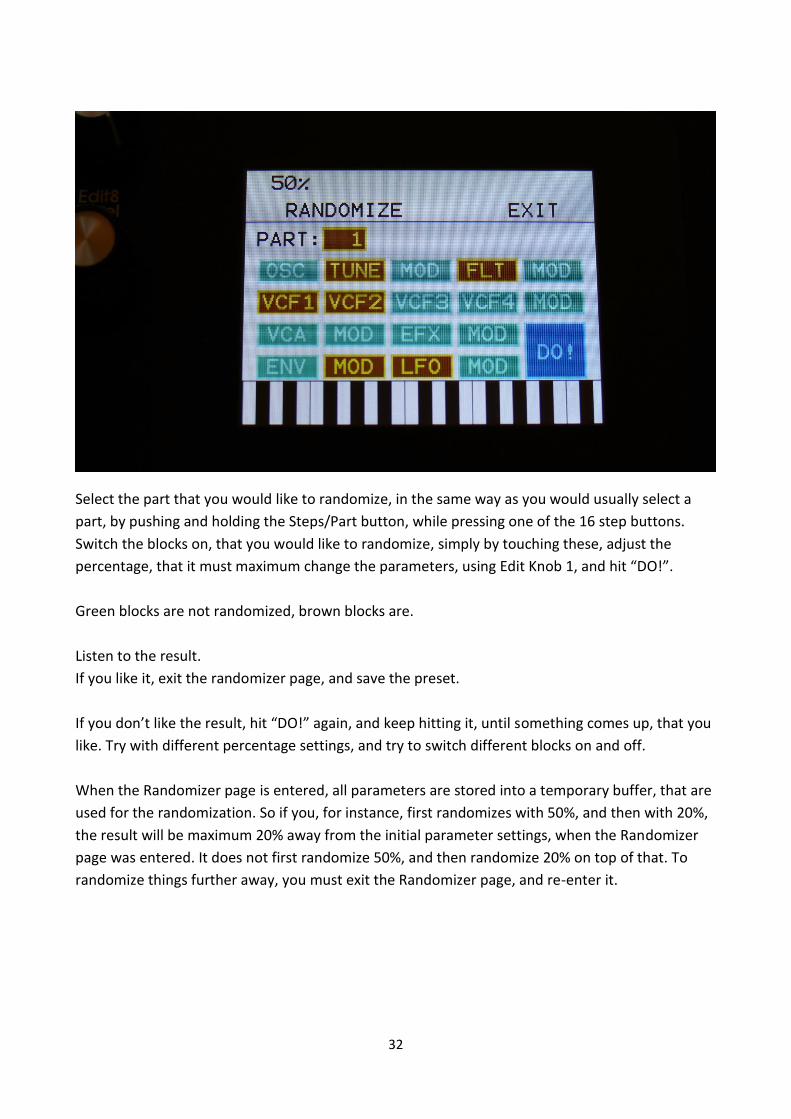
Select the part that you would like to randomize, in the same way as you would usually select a
part, by pushing and holding the Steps/Part button, while pressing one of the 16 step buttons.
Switch the blocks on, that you would like to randomize, simply by touching these, adjust the
percentage, that it must maximum change the parameters, using Edit Knob 1, and hit “DO!”.
Green blocks are not randomized, brown blocks are.
Listen to the result.
If you like it, exit the randomizer page, and save the preset.
If you don’t like the result, hit “DO!” again, and keep hitting it, until something comes up, that you
like. Try with different percentage settings, and try to switch different blocks on and off.
When the Randomizer page is entered, all parameters are stored into a temporary buffer, that are
used for the randomization. So if you, for instance, first randomizes with 50%, and then with 20%,
the result will be maximum 20% away from the initial parameter settings, when the Randomizer
page was entered. It does not first randomize 50%, and then randomize 20% on top of that. To
randomize things further away, you must exit the Randomizer page, and re-enter it.

33
New Insert Effects
Compressor, Expandor, Filters and Filters2 has been added to the Insert Effects.
Compressor
The LD3 compressor damps signals that are above a settable level, in order to make the signal less
dynamic, and easier to record. This is not the same effect as the compressor in LD2. The LD2
compressor has been renamed “Expandor”, and are explained in the next section.
The parameters:
Comp: 0 to 511. Compression amount. The more this is turned up, the more the portion of the
signal, that are higher than the offset value, will be damped.
Offs: 0 to 511. Sets the level point where the compression will kick in. The more this is turned up,
the higher the input signal will need to be, before it starts to compress.
Gain: 0 to 511. Sets the output gain of the compressor.
Time: 0 to 511. The more this is turned up, the longer time it will take, for the compression to kick
in.

34
Rate: 0 to 511. This sets how fast the compressor will react to level changes of the input signal.
The more it is turned up, the slower it will react.

35
Compressor Modulation
Comp1, Comp2: Will modulate the compression amount.
Time: Will modulate the compression “kick in” time.
Rate: Will modulate the time it takes for the compressor to react to changes on the input signal.

36
Expandor
The LD3 Expandor gains signals that are above a settable level, in order to add more kick to
sounds. This is the effect, that was named “Compressor” on the LD2.
The parameters:
Comp: 0 to 511. Compression amount. The more this is turned up, the more the portion of the
signal, that are higher than the offset value, will be gained.
Offs: 0 to 511. Sets the level point where the expansion will kick in. The more this is turned up, the
higher the input signal will need to be, before it starts to gain.
Gain: 0 to 511. Sets the output gain of the expandor.
Time: 0 to 511. The more this is turned up, the longer time it will take, for the expansion to kick in.
Rate: 0 to 511. This sets how fast the expandor will react to level changes of the input signal. The
more it is turned up, the slower it will react.

37
Expandor Modulation
Comp1, Comp2: Will modulate the expansion amount.
Time: Will modulate the expansion “kick in” time.
Rate: Will modulate the time it takes for the expandor to react to changes on the input signal.

38
Filter
This is exactly the same filters, as can be found in the synth parts. They were added to the insert
effects section, in order to make it possible to filter external signals, to build an LD2 style
filterbank, using multiples of these, and because sometimes it is handy to filter some parts of the
other effects or the analog filters out.
The filter types:
LPF1: Lowpass filter with a rather weak character. Resonance does not self-oscillate.
LPF2: Lowpass filter that are a bit sharper than LPF1. Resonance does not self-oscillate.
LPF3: Sharp Lowpass filter with self-oscillating resonance.
LPF4: Very sharp Lowpass filter with self-oscillating resonance.
BPF1: Bandpass filter with a rather weak character. Resonance does not self-oscillate.
BPF2: Bandpass filter with focus on the bass area. Distorts at higher input levels. Resonance does
not self-oscillate.
BPF3: Sharp Bandpass filter with self-oscillating resonance.
HPF1: Sharp Highpass filter with self-oscillating resonance.

39
HPF2: High gained Highpass filter with self-oscillating resonance. Distorts at higher input levels.
HPF3: Sharp Highpass filter with self-oscillating resonance. A bit weaker than HPF1.
Dstr: Destruktion. A rather defective filter. Self-oscillates at some points, distorts at others.
FAT1: Slightly distorting lowpass filter, with a sharp response and self-oscillating resonance.
FAT2: A slightly weaker version of FAT1.
LoFi: A very distorting and unpredictable lowpass filter.
LPF5: A lowpass filter with a very soft character. Resonance does not self-oscillate.
BPF4: A bandpass filter with a very soft character and self-oscillating resonance.
The parameters:
Cut: 0 to 511. Sets the cutoff frequency of the filter.
Reso: 0 to 511. Sets the amount of resonance applied to the filter.
Type: Sets the filter type. See the list of filter types.
Nrw: 0 to 511. Turning this up, will make the frequency response of the filter more and more
narrow.
Low: 0 to 511. Sets the lowest frequency offset point of the filter. Turning this up, will in many
filter types, make the bass bottom more present or distorted.
Boost: 0 to 511. Gains the filter output level.

40
Filter Modulation
Cut1, Cut2: Will modulate the filter cutoff frequency.
Reso: Will modulate the amount of resonance applied to the filter.
Boost: Will modulate the filter output gaining.

41
Filters 2
A different set of digital filters, that is emphazised in the bottom bass area, and has a pretty
uncontrollable resonance.
The parameters:
Cut: Filter cutoff frequency.
Reso: Filter resonance setting.
Type: Filter type. Possibilities are:
-HPF1: High pass filter with extra bass bottom and uncontrollable resonance. -LPF1: Low pass filter with extra bass bottom and uncontrollable resonance. -BPF1: Band pass filter with extra bass bottom and uncontrollable resonance. -HPF2: High pass filter with a thinner and more resonant sound. -LPF2: Low pass filter with a thinner and more resonant sound. -BPF2: Band pass filter with a thinner and more resonant sound.
Growl: Adds unsymmetric distortion to the filter.
Boost: Adds extra boost to the filter output signal, if desired.
Inp: The input level of the filter.

42
Filters 2 Modulation
Cut1, Cut2: Modulates the filter cutoff frequency.
Reso: Modulates the filter resonance.
Inp: Modulates the filter input level parameter.

43
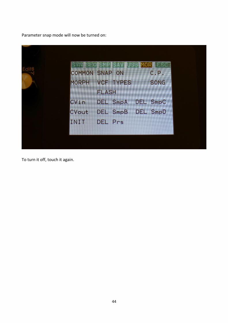
Synth Parameters “Snap” Mode
A synth parameters “Snap” mode has now been added. When this is set to “On”, any synth
parameter value will not be changed, when turning a knob, until it passes the original value, that
the parameter was set to. This will avoid “jumps” in the sound.
On the MOR page, touch the “SNAP OFF” text.
44
Parameter snap mode will now be turned on:
To turn it off, touch it again.
45
Granular Modulators
Each of the 16 synth parts of LD3 has 2 granular modulators, the granular random generator and
the granular sequence modulator, that shows as modulation sources, to any parameter that can
be modulated.
GrRn – Granular Random Generator
This works in conjunction with the part oscillator, sampler or noise generator.
When in oscillator or noise mode:
Every time the synth waveform starts over, the granular random generator puts out a new random
value. When modulating the oscillator wave parameter with this, it will randomly glue different
waveforms together, for granular chaos. Since any parameter can be modulated by this, the
possibilities are endless.
When in sampler mode:
Every time the sampler loops, the granular random generator will put out a new random value. If
you have a wave chopped sampling, and set this parameter up to modulate the chop select
parameter, granular random sample chaos will be obtained. Of course, this can also modulate any
other parameter, for infinite possibilities.
GrSq – Granular Sequence Modulator
This works in conjunction with the part oscillator, sampler or noise generator, and a Sequencer
Controller track. It does not use the output of the controller track directly, only the step values and
the last step parameter.
The oscillator of part 1 uses controller track 17 for sequence values, part 2 uses controller track 18,
part 3 uses controller track 19 and so on…
When in oscillator or noise mode:
Every time the synth waveform starts over, the granular sequence modulator gets the next value
from the associated controller track. When modulating the oscillator wave parameter with this, it
is possible to program wave sequences. Since any parameter can be modulated by this, the
possibilities are endless.

46
When in sampler mode:
Every time the sampler loops, the granular sequence modulator gets the next value from the
associated controller track. If you have a wave chopped sampling, and set this parameter up to
modulate the chop select parameter, it is possible to program wave sequences. Of course, this can
also modulate any other parameter, for infinite possibilities.

47
Part Poly and Mono To Voice Modes
On the TRIG page, accessed from the synth parts main page, each part can be set in either
polyphonic mode, or mono to a specific voice mode. The mono to voice mode reserves a voice for
that part, and makes sure, that this voice can only be taken by other parts that are mono assigned
to the same voice. Polyphonic parts do not use the voices that are assigned to parts. This can
prevent long samplings from being cutted off, and it can be used if you have one or more groups
of samplings, that you would like to cut each other off.

48
Output Effects Feedback BUS
A new Feed parameter on the output effects pages, lets you set the feedback loop of the effect to
either Int (internal –like before), or to run through any of the 8 audio busses.
This lets you add other effects and filters inside the feedback loop of the output effect, for new
effect possibilities. Add a lowpass filter to make the feedback sound get more and more dark. Add
a pitch shifter in a delay loop, for a pitch shifting delay effect. There are really many possibilities
with this.
Busses that are assigned to an output effect feedback loop, will no longer output to the audio
outputs, that they were assigned to.

49
Sample Loop Smoothing
On the synth parts sampler pages, the Xfade parameter can now be set to “Smth” –Smooth.
The smooth function will shortly damp the level of a sampling, at the moment that it loops. This
will, in many cases, remove clicks from a loop.

50
New Sample Chop Modes
The parameter on the Sample Chops page, that was named Wave in previous OS versions, has now
been renamed to Mode.
The following chop modes, that determines how LD3 will chop a sampling, can now be selected:
Peak: It will generate the chop points from peak detection, according to the settings of the Sens
and Dec parameters. The same way as it did in previous OS versions, when Wave was set to off.
Wave: It will generate the chop points from zero point detection, according to the settings of the
Sens and Dec parameters. The same way as it did in previous OS versions, when Wave was set to
on. When auditioning chops in this mode, the playback will be looped.
A number between 2 and 64: It will divided the sample length by the selected number, and
generate the chop points from that, regardless of the settings of the Sens and Dec parameters.

51
New Synth Part Samplers Loop Modes
In previous OS versions, when chop points were generated for a sampling, selected in the part
oscillators, it would always play back the chops.
Now 2 new loop modes has been added, OfUc (Loop off, un-chopped) and OnUc (Loop on, un-
chopped). When set to any of these loop modes, the chop points will be ignored, and it will just
play back the sampling from start to end.

52
Sequencer Step Recording
A step recording method has now been added to the LD3 sequencer, on top of the xox and
realtime recording methods.

53
On the sequencer main page, it is by the StAdv (Step Advance) parameter possible to set, if the
sequencer, when step recording, should automatically advance to the next step or not.
Rec mode can be set to either mono or poly.
To initiate step recording:
-Set LD3 in sequencer recording mode, by touching the REC field on the sequencer main page or
on the preset select page, so that it turns red, or push and hold the Func/Mute button, while
pressing the Start/Stop button.
-Start the sequencer playback, if desired. Step recording is possible no matter if the sequencer is
running or not.
-Push and release the Steps/Part button, so that it lights up, and puts the 16 step buttons in step
mode.
-Push the step button, that has the position for the step, that you would like to record. This will
now flash.
-Play a note (or more in poly rec mode), on an attached MIDI device or on the touch screen
keyboard. This will now be recorded. If any controller track is set in recording mode (explained in
the next section), MIDI CC’s and knob movements can also be recorded to specific steps this way.
-If Step Advance is set to on, LD3 will advance to the next step, everytime it receives a note off.
-Else, now select another step to record.

54
If the sequencer is running, while step recording, the time you hold down a note, will be recorded.
If the sequencer is stopped, resolution will determine the note length.
55
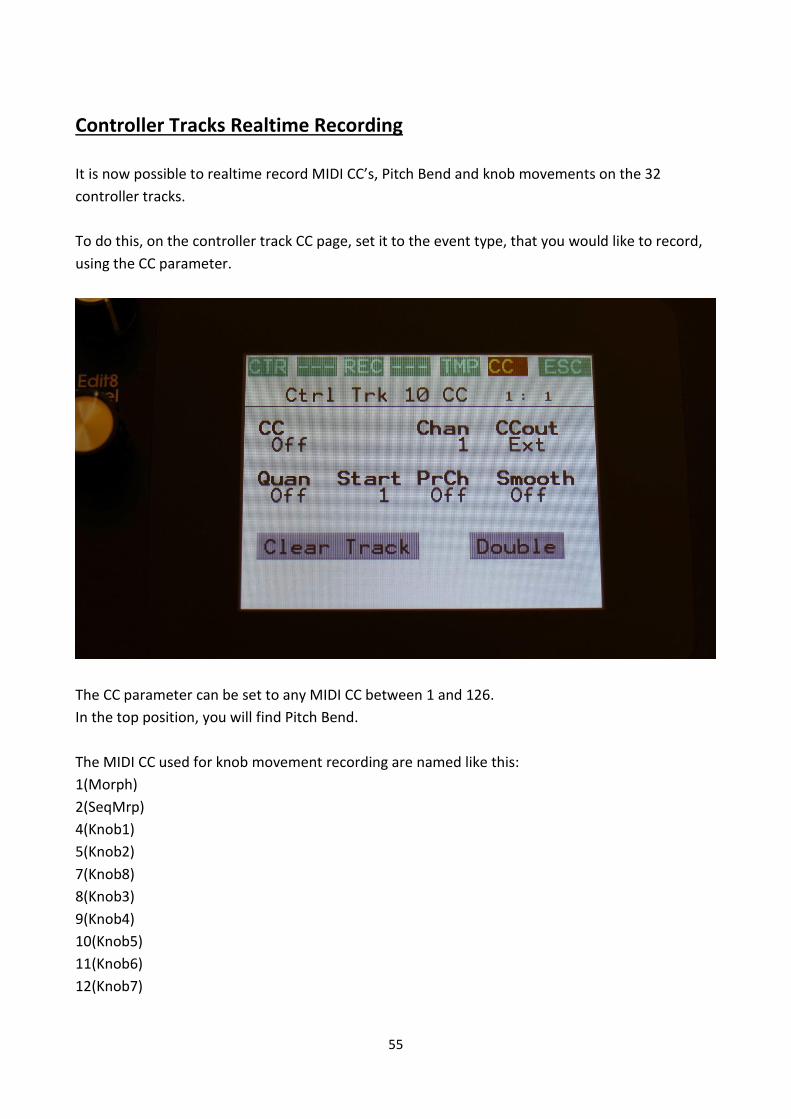
Controller Tracks Realtime Recording
It is now possible to realtime record MIDI CC’s, Pitch Bend and knob movements on the 32
controller tracks.
To do this, on the controller track CC page, set it to the event type, that you would like to record,
using the CC parameter.
The CC parameter can be set to any MIDI CC between 1 and 126.
In the top position, you will find Pitch Bend.
The MIDI CC used for knob movement recording are named like this:
1(Morph)
2(SeqMrp)
4(Knob1)
5(Knob2)
7(Knob8)
8(Knob3)
9(Knob4)
10(Knob5)
11(Knob6)
12(Knob7)

56
For knob movement recording, you should select one of these.
Set CCout to Int (internal) or Ext (external), depending on, if you like the controller track to control
LD3 itself, or some external MIDI gear.
Set the track to the desired MIDI channel, using the Chan parameter. If the track is set to internal
operation, the channel number is the part number, that the track will output to.
Touch REC on the top navigation bar, to enter this page:
Select the controller track(s), that you would like to realtime record, by touching the square, that
has the same number(s) as the track(s), so that these turns red.
Set the length of the controller tracks(s), if desired.
Now set LD3 in sequencer recording mode, by touching the REC field on the sequencer main page
or on the preset select page, so that it turns red, or push and hold the Func/Mute button, while
pressing the Start/Stop button.
Start the sequencer. Tweak the knobs and/or MIDI CC’s.

57
The controller tracks, that are set in record mode, will record until the track reaches the last step,
and starts over again. Then recording will switch off.
It is also possible to step record controller events, as described in the previous section. Rec must
also be switched on, for a controller track, in order to step time record it.

58
Sequencer Tracks Double Button
On the note and controller tracks, a Double touch button has been added.
When touching this, the length of the track is doubled, and the events from the original track, is
copied to the new half. Useful if you need some extra variation in a track.
PLEASE NOTE: The track lengths cannot exceed 64 steps for the note tracks and 128 steps for the
controller tracks.

59
Sub Position Track
When on a note track Position track, touch POS in the top navigation bar an extra time, and you
will access the sub position track.
Here it is possible to move a note step up to 3 tics forward, in order to get a more loose timing.

60
Controller tracks Pitch Bend
CC 127 on the controller tracks CC parameter, has now been replaced by Pitch Bend. It is possible
to make a controller track transmit pitch bend messages either to an internal synth part, or to
external MIDI gear, as selected by CCout.
The part/MIDI channel, that the pitch bend messages is sent to, are selected using the Chan
parameter.
By using the controller tracks realtime record function, explained earlier in this manual, it is even
possible to record pitch bend messages to the controller tracks.

61
Controller Tracks Internal/External operation
The controller tracks can now be set up to transmit MIDI CC’s either internally or externally, by
setting the CCout parameter, on the controller tracks CC pages.
When set to internal (Int), the track will transmit MIDI CC’s to any parameters that is set up for
MIDI CC control. When CC is set to pitch bend, it will transmit pitch bend messages to the part
selected by the Chan parameter.
When set to external (Ext), the track will transmit MIDI CC’s or pitch bend messages to the LD3
MIDI out, on the channel selected by the Chan parameter.
Please notice, that this only affects parameters that are set up for MIDI CC control, not
parameters that is set up for sequencer controller track control. These will always be modulated
regardless of the CCout setting.

62
Controller Tracks Program Change
When setting the PrCh parameter to any value between 1 and 128, a program change message
will be transmitted on MIDI out, on the MIDI channel selected by the Chan parameter, every time
this preset is selected. The CCout parameter has no effect on this.
Each of the 32 controller tracks can transmit its own program change.

63
Audio BUS Page –New parameters and VU-Meters
On the audio BUS pages, that are accessed from the synth parts main page, by touching BUS, VU-
meters has now been added, to make it easier to see, what is going on, on each BUS.
Since the parameters of the Bus pages are not explained in the currently available Quick Manual, I
will describe all the parameters here, both the previous and the new ones.
On this first bus page, it is possible to select the output, that each of the 8 Busses will go to.
Possibilities are:
L: The output of the Bus is sent to the left audio output.
R: The output of the Bus is sent to the right audio output.
L+R: The output of the Bus is sent to the left and the right audio outputs.
EFX1: The output of the Bus is sent to Output effect 1.
EFX2: The output of the Bus is sent to Output effect 2.
3: The output of the Bus is sent to the optional audio output 3.
4: The output of the Bus is sent to the optional audio output 4.
5: The output of the Bus is sent to the optional audio output 5.
6: The output of the Bus is sent to the optional audio output 6.
3+4: The output of the Bus is sent to the optional audio outputs 3 and 4.
5+6: The output of the Bus is sent to the optional audio outputs 5 and 6.

64
Off: The output of the Bus is not sent anywhere.
PLEASE NOTE: Audio busses that are assigned to be placed inside an output effect feedback loop,
will ignore this setting, and only output to the effect feedback input.

65
On this second audio Bus page, it is possible to adjust the release time of the envelope follower,
that are attached to each audio Bus, and that affects the output levels of these.
When this is set to 511, the follower will never decay. When set to lower values, the follower will
gradually decay, in accordance with the levels of the audio signal sent to it, from the synth parts.

66
On this third audio Bus page, it is possible to gain or attenuate the level of the audio signal sent to
the Bus envelope follower. At +0, there are no gaining or attenuation. At positive values the signal
to the follower is gained, at negative values, they are attenuated.

67
NEW PARAMETERS!
On the fourth audio Bus page, it is possible to adjust the total output level of each Bus. Positive
values will gain the output signal, negative values will attenuate.
68
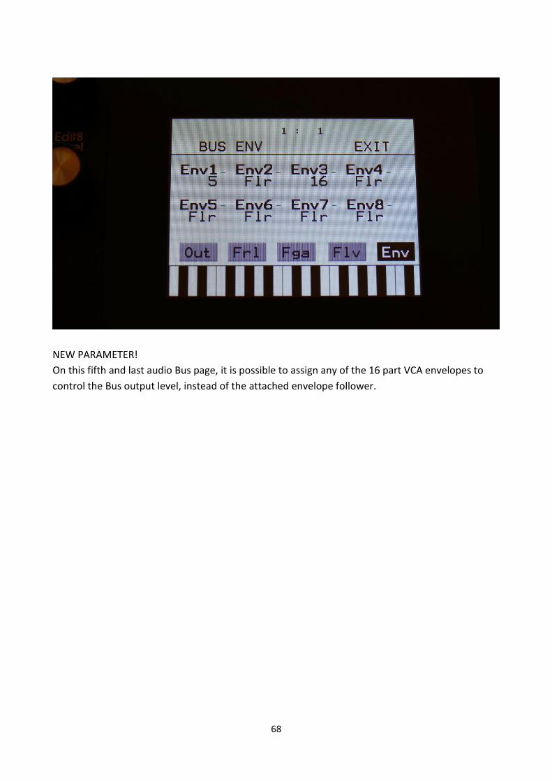
NEW PARAMETER!
On this fifth and last audio Bus page, it is possible to assign any of the 16 part VCA envelopes to
control the Bus output level, instead of the attached envelope follower.

69
Audio Inputs BUS select Page
On this page, that is accessed from the synth parts main page, it is possible to set up, which audio
Bus each audio input should be sent to.
VU-meters has now been added on this page, to make it easier to monitor, what is going on, on
each audio input.

70
SPAZEboard2
This update will make LD3 compatible with SPAZEboard2.
SPAZEboard2 comes with 2 dual Spaze filters installed, that are almost the same as 2x VCF8, dual
band SSI filter, plus it has room for 2 FilterBoards. 4 analog filter chains in total!
In order to make room enough for this, the 2 FilterBoards will need another type of connectors
installed, in order to fit SPAZEboard2.
VCF1 and VCF4 –Dual Spaze filters
Each of the two dual Spaze filters has 2 filter lines, that each has a 24dB analog highpass filter,
going into a 24 dB analog lowpass filter.

71
The parameters:
HpCut: 0 to 511. The cutoff frequency of the highpass filters in both filter lines.
LpCut: 0 to 511. The cutoff frequency of the lowpass filters in both filter lines.
Reso: 0 to 511. The amount of resonance applied to all of the 4 filters.
Spaze: -255 to +256. The difference between the cutoff frequencies in the 2 lines of filters.
Inp: 0 to 511. The audio input level for the filters.
Outp: -128 to +383. The output level of the filters.
FM: 0 to 511. The amount of frequency modulation (audio range), that are applied to all of the
filter cutoff frequencies, from the audio Bus selected by the FmBus parameter.
FmBus: 1 to 8. The audio bus, that will apply the audio signal for FM.

72
G-Ray: Adjusts the amount of g-RAY intermodulation. 0: no g-RAY, 3: max g-RAY. Range: 0 to 3.
Mode: G-Ray mode.
-Norm: Normal 1:1 feedback. -Neg: 1:1 feedback with the signal inverted (a 180 degree phase shift) -Ultr: Boosted feedback. -Uneg: Boosted feedback with the signal inverted (a 180 degree phase shift) Feed: G-Ray feedback level. Range: 0 to 511.

73
HCut1, HCut2: Will modulate the Cutoff Frequency of both the highpass filters.
LCut1, LCut2: Will modulate the Cutoff Frequency of both the lowpass filters.

74
Reso: Will modulate the amount of resonance applied to all filters.
Spaze: Will modulate the difference between the cutoff frequencies of the 2 filter lines.
FFM: Will modulate the amount of frequency modulation applied to the cutoff frequencies of all
the filters.
Gfeed: Will modulate the amount of G-Ray feedback applied.

75
Bus: 1 to 8. The audio Bus, that the filter will be placed on.
Inp: 0 to 511. The audio input level for the filters.
Outp: -128 to +383. The output level of the filters.
Conn: Ser/Par. (Only on VCF2, 3 and 4). Places this filter in either serial or parallel connection to
the lower numbered filter.
ModPrt: 1 to 16. The part from which, the filter modulation sources will be added.

76
VCF2 and VCF3 – FilterBoards
On the VCF2 and 3 pages, when Spazeboard2 are installed, only the standard filterboard
parameters are shown, regardless of which filterboards are installed. The parameter names filts to
VCF 1, 2 and 4. Other filterboards has different functions on some parameters.
The parameters:
Cut: 0 to 511. Adjust the filter cutoff frequency.
Peaks: 0 to 511.
On single filters: If the filter has more than one filter block, this will adjust the cutoff frequency
offset of block 2 or block 3+4. If the filter has only one block (see the documentation for the filter),
this will have no function.
On dual filters: This will adjust the cutoff frequency offset of filter 2.
On tripple filters: This will adjust the cutoff frequency offset of the middle filter, which is usually a
bandpass filter.
Reso: 0 to 511. Adjusts the amount of resonance applied to the filter. On dual and tripple filters,
this adjusts the resonance on all filters.

77
Cut3/Feed: 0 to 511.
On single filters: This will adjust the feedback of the filter. – means negative feedback, + means
positive feedback, 0 means no feedback.
On dual filters: This will adjust the negative feedback of the filter. -256 means no feedback, +255
means full negative feedback.
On tripple filters: This will adjust the cutoff frequency of the third filter.
LPF, BPF, HPF: On/Off.
On single filters: Switches on and off the low pass, band pass and high pass outputs on the filter.
At least one of these must be on, to get a sound out of the filter.
On dual filters: Switches on and off the low pass, band pass and high pass outputs of filter 2. Filter
1, which is a band pass filter on VCF2, is always on.
On tripple filters: Switches on and off the low pass, band pass and high pass outputs of filter 1, 2
and 3. The tripple filter has 3 separate filters, to generate each of these outputs, and their cutoff
frequency can be separately adjusted.
Out1/2: 0 to 511.
On single and dual filters: Mix between the clean filter sound, and the filter sound with added
analog distortion.
On tripple filters: Mix between LPF + BPF + HPF and 3x BPF.
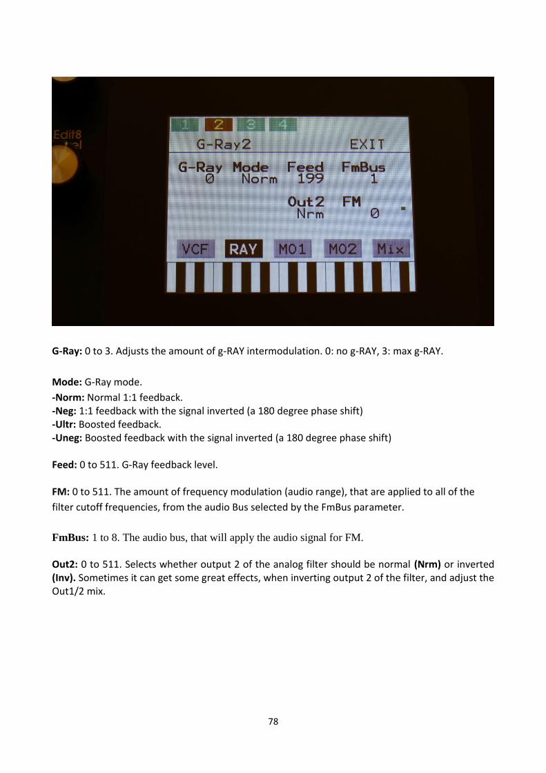
78
G-Ray: 0 to 3. Adjusts the amount of g-RAY intermodulation. 0: no g-RAY, 3: max g-RAY.
Mode: G-Ray mode.
-Norm: Normal 1:1 feedback. -Neg: 1:1 feedback with the signal inverted (a 180 degree phase shift) -Ultr: Boosted feedback. -Uneg: Boosted feedback with the signal inverted (a 180 degree phase shift) Feed: 0 to 511. G-Ray feedback level. FM: 0 to 511. The amount of frequency modulation (audio range), that are applied to all of the
filter cutoff frequencies, from the audio Bus selected by the FmBus parameter.
FmBus: 1 to 8. The audio bus, that will apply the audio signal for FM. Out2: 0 to 511. Selects whether output 2 of the analog filter should be normal (Nrm) or inverted (Inv). Sometimes it can get some great effects, when inverting output 2 of the filter, and adjust the Out1/2 mix.

79
Cut1, Cut2: Will modulate the Cutoff Frequency.
Peak1, Peak2: Will modulate the Peaks parameter.
80
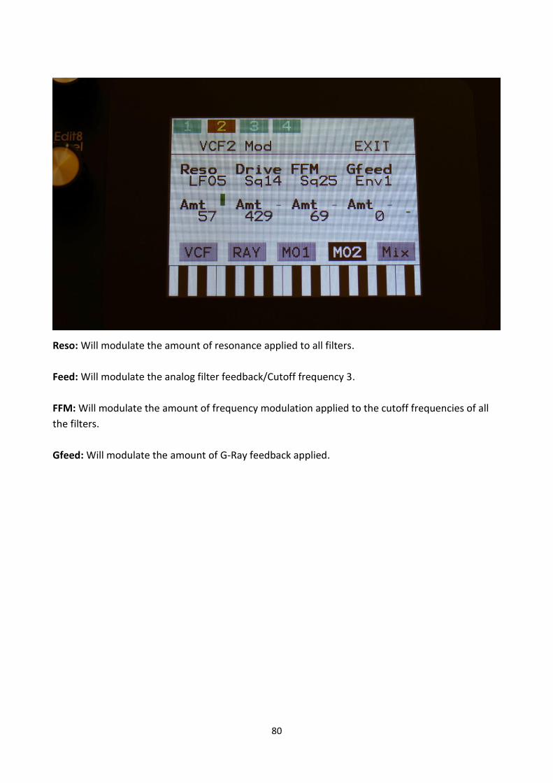
Reso: Will modulate the amount of resonance applied to all filters.
Feed: Will modulate the analog filter feedback/Cutoff frequency 3.
FFM: Will modulate the amount of frequency modulation applied to the cutoff frequencies of all
the filters.
Gfeed: Will modulate the amount of G-Ray feedback applied.

81
Bus: 1 to 8. The audio Bus, that the filter will be placed on.
Inp: 0 to 511. The audio input level for the filters.
Outp: -128 to +383. The output level of the filters.
Conn: Ser/Par. (Only on VCF2, 3 and 4). Places this filter in either serial or parallel to the lower
numbered filter.
ModPrt: 1 to 16. The part from which, the filter modulation sources will be added.

82
Sample Rec Monitor Rec Mode
The sample rec monitor, that passes audio through from the audio inputs selected as sample
recording source, to the main audio outputs, when on, now has gained some extra functionality.
Besides from the settings Off and On, it can now also be set to Rec. When in this mode, it will only
pass audio through, the moment that LD3 is actually recording a sampling. This is useful, when
recording audio tracks from a source, that is synced to LD3 (via MIDI or analog clock).

83
Controller tracks CV quantize
A CV Quantize parameter (Quan) has been added to the sequencer controller tracks. This can be
set to scale the output of the controller tracks to 1v/oct or 1.2v/oct. Useful when controlling
analog synths from the optional CV outputs of LD3.

84
“Panic” Function
A “PANIC” function has now been added, that shuts all notes off on LD3 and on any connected
MIDI devices.
Push and release the Func/Mute button, so that it lights up, to enter the function buttons. Now
push and release step button 13 (Copy), so that this also lights up. Instructions for copy and panic
will now be shown on the screen. Push and release step button 16 (Exit).
Now all notes, both internally and on any MIDI devices connected to the LD3 MIDI out, will be
shutted off.

85
Rec state and Tempo on the Preset Select Page
Sequencer Record state and tempo are now shown on the main preset select page. Realtime
record can be activated/deactivated by touching the status indicator, and the sequencer main
page, where the tempo can be set, will be accessed directly, by touching the tempo indicator.

86
USB Sample Preview
Wav samples can now be previewed directly from a USB drive (LD3 has always had this function,
but I forgot to mention it in the first Quick Manual).
Select the sampling, that you would like to preview, by touching the sample name, and touch the
PREW touch button. This will first show LOAD, then PREW again, while playing back the first 6
seconds of the sampling.

87
USB Import Sample Bank Select
In the previous LD3 OS, you would have to go all the way back to the Sample Rec page, to select
the sample bank, that LD3 would import samples to from a USB drive. Not any more!!!
Now, while on the USB pages, simply select a folder, touch the Import touch button, and the page
showed above will turn up.
Select the import sample bank, using Knob 1.
If you do not wish to import a whole folder of samplings, touch No, to exit from this page.

88
CV Outputs Modulation Part
Modulation part 1 to 16 can now be selected for each of the CV outputs, by setting the ModP
parameters.

89
Analog Triggers
The trigger of each of the 16 parts has been added to the modulation sources. This will send out a
maximum modulation value, every time a part is trigged, either from the trigger buttons, the
touch screen keyboard, the sequencer or an external MIDI device.
This is useful for gating analog synths via the CV outputs.

90
MIDI CC’s as Modulation Sources
MIDI CC 17 to 61 (named CC17 to CC61) has been added as modulation sources.

91
3 Extra Random Generators
3 extra Random Generators (named Rnd2 to Rnd4) has been added as modulation sources, per
part.
Like the first one, they are all trigged by the part trigger. Now it is possible to get different random
values on different parameters.

92
Preset Preview
The preset preview function did not work in the first LD3 OS. Now it does!
When on the select preset page, touch the PreView touch button, so that it turns black. Now you
can preview presets, without LD3 jumping back to the main preset select page.
If the sequencer is running, it will still wait for track 1 to reach step 1, until it jumps to the next
preset. This is indicated by the Start/Stop LED flashing.

93
Sequencer Clear Track
In the previous LD3 OS, when clearing a track, the steps were just turned off. Now all values are
reset, except for the last stet values.

94
Sequencer Main Escape
In the previous LD3 OS, I forgot to add an Exit/Escape button on the Sequencer Main page. It was
though still possible to exit from the sequencer main page, by touching the upper right corner.
BUT NOW IT’S THERE!!!

95
LFO’s Key Sync
The LFO key sync was only partly working in the first LD3 OS. Now it is fully working. Set the KeyS
parameter to part 1 to 16, and the LFO will key sync to this part.

96
Updating the LD3 firmware
Now and then updates will be available for LD3, that adds new functionality and fixes bugs. These will always be available for download at: http://www.gotharman.dk To update LD3, you must have a computer with an internet connection, and an LD3 compatible USB drive ready. See the start of this section, for which USB drives that are LD3 compatible. Then you should follow these steps:
1. Download the update file of the latest update, from the LD3 Updates site, to your computer.
2. Unzip the file.
3. Connect the USB drive to your computer.
4. Make sure that the USB drive is FAT formatted.
5. Create a directory in the root directory of this USB drive, that is named "UPDATE".
If the USB drive already contains a directory called UPDATE, please delete all files inside this.
6. Copy the update file from your computer to the USB drive UPDATE directory. Make sure that no
other files are present in this folder, and please don’t rename the files.
7. Eject and remove the USB drive from your computer, and connect it to LD3 's USB connector.
8. Turn LD3 on, if it isn’t already turned on.
9. From the preset select screen, touch the EDIT field.
10. Touch USB.
11. Wait for LD3 to register the USB drive, so all files and folders are presented on the screen.

97
12. Touch the "UPD" button.

98
13. LD3 will now search for the "UPDATE" folder and a valid update file. If it finds both, it will ask:
"Update Firmware?"
14. Touch "Yes" to proceed with updating, or "No" if you regret.

99
15. If you pushed Yes in step 13, LD3 will now start to get the update file, and program its
processor.
When it starts to program the processor, it will look like it halts for a couple of minutes. This is
because it does halt, when erasing the program memory of a processor.
Erasing the program memory of the processor:

100
Programming processor (counter in the bottom counts up):

101
16. When programming is done, LD3 will ask you to restart it. Please turn LD3 off and then on
again.

102
17. When you turn on LD3 after an update, it will need to finalize this. It will show this by turning
10 step button LED’s on and off sequentially, one by one. After it has done this for a little while, it
will start normally and are ready to use.
While it is finalizing the update, an initial text will show on the display:
If something goes wrong:
-If the power should go off, while LD3 is getting the update from the USB drive, and programming
the processors, simply start over again from step 7.
-If the power should go off, while LD3 is finalizing the update (3 LED's turn on and off), simply turn
LD3 on again, and it will now finalize the update.

103
Written by:
Flemming Christensen
Gotharman
2018