Embed Size (px)
Citation preview
UK | DOC 0080 | Rev 2.1 | January 2016
Grant Vortex Eco
Utility and System Floor Standing Condensing Oil Boiler Range
Installation and Servicing Instructions
????
???
22
Important NoteFor use with Kerosene* only.
After installing the boiler leave these instructions with the User.
This appliance is deemed a controlled service and specific regional statutory requirements may be applicable.
*Operation on Bio-fuelAll Grant Vortex Eco condensing boilers, manufactured since May 2011, are suitable for operation on both standard kerosene (Class C2 to BS2869) and also bio-kerosene – up to a 30% blend (B30K).
All burner settings and nozzle sizes (as detailed in Section 2.3 of this manual) are correct for both standard kerosene and bio-kerosene (B30K).
In order to operate this boiler on bio-kerosene it will be necessary to take the following actions:
• Use a bio-kerosene (B30K compatible flexible oil line in place of the oil line supplied with this boiler.
• Have your oil storage tank and oil supply line (including all pipework, sight gauges, filters, isolating valves, fire valves, ed-aeration devices, etc.) checked for their compatibility with bio-kerosene (B30K).Where necessary some, or all, of these items may have to be replaced with a bio-kerosene compatible alternative.
• Check the suitability of the flue system with Grant UK.
• Use only bio-kerosene (B30K) that conforms to OPS24.
IMPORTANTUnder no circumstances should the boiler be used with bio-kerosene without the above actions being taken first.
GRANT ENGINEERING (UK) LIMITEDHopton House, Hopton Industrial Estate, Devizes Wiltshire SN10 2EUTel: +44 (0)1380 736920 Fax: +44 (0)1380 736991Email: [email protected] www.grantuk.comThis manual is accurate at the date of printing but will be superseded and should be disregarded if specifications and/or appearances are changed in the interests of continued product improvement.All good sold are subject to our official Conditions of Sale, a copy of which may be obtained on application.© Grant Engineering (UK) Limited 2015. No part of this manual may be reproduced by any means without prior written consent.
Date:______________________________
Commissioning Engineer:_____________________________________________________
Tel. No:____________________________
Boiler model:_______________________ Boiler output:________________ kW
Fuel type: Kerosene / Bio-Kerosene
Nozzle size:________________________ Pump pressure:_____________________
Air setting:_________________________ Flue gas % CO2:____________________
Net flue gas temp:___________________ Smoke No:_________________________
System flushed: yes / no Corrosion inhibitor added: yes / no
Antifreeze added: yes / no
For Sealed systems only:
Expansion vessel size:______________________ litres
Expansion vessel charge pressure:___________ bar
Sealed system fill pressure (cold):____________ bar
Service Log
It is recommended that the boiler should be regularly serviced, at least once a year, and the details entered in the Boiler Handbook by the service engineer.
Declaration of Conformity
We declare that the Grant VORTEX range of Oil Boilers equipped with Riello RDB burners approved to EN 267: 1999 satisfy the requirements of the following European Directives:
1. 89/336/EEC - Electromagnetic Compatibility DirectiveReferred to the generic standards EN 55014: 1993, EN 50082: 1: 1992
2. 73/23/EEC - Electrical Equipment Safety Regulations DirectiveReferred to the generic standard NO: 3260: The Electrical Equipment (Safety) Regulations: 1994
3. 92/42/EEC - Hot Water Boiler Efficiency DirectiveReferred to the generic standard The Boiler (Efficiency) (Amendment) Regulations 1994 (SI 1994/3083)
3
Contents1 Introduction 4 1.1 How a condensing boiler 4
works
1.2 Boiler description 4
1.3 Boiler components 5
2 Technical Data 6 2.1 Boiler technical data 6
2.2 Sealed system data 7
2.3 Vortex boilers using Class 7
C2 kerosene
2.4 Flue gas analysis 7
2.5 Water connections 7
2.6 Boiler dimensions 8
3 Oil Storage and Supply 9 System 3.1 Fuel supply 9
3.2 Burner oil connection 11
4 Boiler Installation 13 Information 4.1 Introduction 13
4.2 Boiler location 13
4.3 Preparation for installation 13
4.4 Installing the boiler 13
4.5 Regulations compliance 13
4.6 Completion 14
4.7 Before you commission 14
4.8 Heating system design 14
considerations
4.9 Underfloor heating systems 14
4.10 Pipework materials 14
4.11 Sealed systems 14
4.12 Underfloor pipework 14
5 Pipe Connections 15 5.1 Water connections 15
5.2 Water connections - system 15
models
6 Condensate Disposal 16 6.1 General requirements 16
6.2 Connections 16
6.3 Pipework 16
6.4 External pipework 16
6.5 Condensate soakaway 16
6.6 Condensate trap 17
6.7 Condensate disposal 17
pipework
6.8 Inspection and cleaning of 17
trap
6.9 Relocate the trap 18
7 Sealed Systems 19 7.1 Sealed system installation 19
7.2 Sealed models 20
7.3 Fill the sealed system 20
7.4 Pressure relief safety valve 20
7.5 Circulating Pump 21
8 Electrical 23 8.1 Connecting the power 23
supply
8.2 Frost protection 23
8.3 Control system wiring 24 diagrams
8.4 Boiler control panel wiring 25 diagram
9 Flue and Air Supply 26 9.1 Air supply 26
9.2 Conventional flue systems 27
9.3 Connecting a conventional 29
flue
9.4 Balanced flue system 30
9.5 Prepare the wall 35
9.6 High level and vertical 35
balanced flue
10 Commissioning 36 10.1 Before switching on 36
10.2 Switching on 37
10.3 Running the boiler 37
10.4 Balancing the system 37
10.5 Completion 37
10.6 Air adjuster disc - 15/21 only 38
11 Boiler Servicing 39 11.1 Checking before servicing 39
11.2 Dismantling prior to servicing 39
11.2 Cleaning the boiler 39
11.4 Cleaning the burner 41
12 Fault finding 42 12.1 Boiler fault finding 42
12.2 Burner fault finding 43
12.3 Circulating pump fault 44
diagnosis
13 Spare Parts 45 13.1 Boiler spares 45
13.2 Burner heads 45
13.3 Riello RDB2.2 burners 46
14 Health and Safety 48 Information 14.1 Insulation materials 48
14.2 Sealant materials 48
14.3 Kerosene and gas oil fuels 48
(mineral oils)
15 Recycling and Disposal 49
16 Guarantee 50
17 Notes 52

4
1 IntroductionThis manual is intended to guide Installers who have completed the Grant Wood Pellet Boiler Installer training course on the installation, commissioning and servicing of the Grant Spira Condensing Wood Pellet Boiler.
A separate manual is available to guide users in the operation of the boiler.
The following special text formats are used in this manual for the purposes listed below:
! WARNING
1.1 How a Condensing Boiler WorksDuring the combustion process, hydrogen and oxygen combine to produce heat and water vapour. The water vapour produced is in the form of superheated steam in the heat exchanger. This superheated steam contains sensible heat (available heat) and latent heat (heat locked up in the flue gas). A conventional boiler cannot recover any of the latent heat and this energy is lost to the atmosphere through the flue.
The Grant Vortex Eco condensing boiler contains an extra heat exchanger which is designed to recover the latent heat normally lost by a conventional boiler. It does this by cooling the flue gases to below 90°C, thus extracting more sensible heat and some of the latent heat. This is achieved by cooling the flue gases to their dew point (approximately 55°C).
To ensure maximum efficiency, the boiler return temperature should be 55°C or less, this will enable the latent heat to be condensed out of the flue gases.
• The boiler will achieve net thermal efficiencies of 100%.
To achieve maximum performance from the Grant Vortex Eco boiler, it is recommended that the heating system is designed so that a temperature differential of 20°C between the flow and return is maintained. The use of modulating circulating pumps (now widely available) and effective control systems should be considered.
The Grant VORTEX Eco boiler will however still operate at extremely high efficiencies even when it is not in condensing mode and therefore is suitable for fitting to an existing heating system without alteration to the radiator sizes. The boiler is capable of a maximum flow temperature of 75°C.
1.2 Boiler DescriptionThe Grant VORTEX Eco range of automatic pressure jet oil boilers have been designed for use with a fully
pumped central heating system with indirect domestic hot water cylinder.
They are not suitable for use with either a direct cylinder or a ‘primatic’ cylinder or gravity hot water.
The boilers are suitable for use on open vented or sealed central heating systems.
The boilers are supplied with the control panel and burner factory fitted.
The boilers can be connected to either a conventional flue system or a balanced flue system, as required.
For Conventional Flue Applications
Where a chimney is to be lined - Grant recommends the use of the Grant ‘Orange’ flue system, specifically designed for the Vortex range of condensing boilers. Refer to Section 9.2 for further details.
Where a rigid conventional flue - either internal or external - is required, Grant recommends the use of the Grant ‘Green’ and ‘Orange’ flue system
components. As no flue adaptor is supplied with the boiler it will be necessary to purchase the Grant CF adaptor kit in order to correctly connect this system to the boiler.
Flue adaptor kit (product code: CFA15/70) is used for all models as they all use the 100 mm ‘Green’ and ‘Orange’ system components to construct a flue of maximum vertical height 19 metres.
For Balanced Flue Applications
The following flue kits are available from Grant UK. Refer to Section 9.4.
Yellow system
Standard low level concentric balanced flue - components available:• Low level concentric balanced flue• short• Extensions 225 mm, 450 mm and
675 mm• 90° extension elbow• 45° extension elbow• 45° elbow• Plume diverter kits
Green system
Standard external high level/vertical flue starter kit (room sealed) - components available:• External high level/vertical flue
starter kit short (room sealed)• Extensions 150 mm, 250 mm, 450
mm, 950 mm• Adjustable extension 195 to 270
mm• 45° elbow• High level terminal• Vertical terminal
Warning of possible human injury as a consequence of not following the instructions in the “warning”.
Used for emphasis or information not directly concerned with the surrounding text but of importance to the reader.
Caution concerning likely damage to equipment or tools as a consequence of not following the instructions in the “Caution”.
! CAUTION
! NOTE
! NOTEThe flue system materials andconstruction MUST be suitablefor use with oil-fired condensingboilers. Failure to fit a suitableconventional flue may invalidate theguarantee on the boiler.
5
White system
High level and vertical concentric balanced flue kit - components available:• Extensions 225 mm, 450 mm, 950
mm• Adjustable 275 to 450 mm• Vertical concentric balanced flue kit• Extensions 225 mm, 450 mm, 950
mm• Adjustable extension 275 to 450
mm• 45° elbow
Red system (15/21 and 21/26 only)
A flexible vertical balanced flue system designed to be fitted inside an existing masonry chimney.
Consisting of three sections:• Concentric white painted flue pipe
connected to the boiler• Vertical concentric flexible flue
(flexible stainless steel twin-wall liner inside a stainless steel single-wall liner
• Terminal assembly for chimney top mounting
Flue extensions and 45° elbows from the White system may be used.
Fitting instructions for the Low level, High level and Vertical balanced flue systems are supplied with the kits.
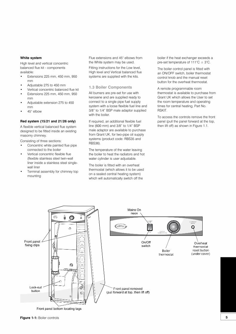
1.3 Boiler ComponentsAll burners are pre-set for use with kerosene and are supplied ready to connect to a single pipe fuel supply system with a loose flexible fuel line and 3/8” to 1/4” BSP male adaptor supplied with the boiler.
If required, an additional flexible fuel line (600 mm) and 3/8” to 1/4” BSP male adaptor are available to purchase from Grant UK, for two-pipe oil supply systems (product code: RBS35 and RBS36).
The temperature of the water leaving the boiler to heat the radiators and hot water cylinder is user adjustable.
The boiler is fitted with an overheat thermostat (which allows it to be used on a sealed central heating system) which will automatically switch off the
boiler if the heat exchanger exceeds a pre-set temperature of 111°C ± 3°C.
The boiler control panel is fitted with an ON/OFF switch, boiler thermostat control knob and the manual reset button for the overheat thermostat.
A remote programmable room thermostat is available to purchase from Grant UK which allows the User to set the room temperature and operating times for central heating, Part No. RSKIT.
To access the controls remove the front panel (pull the panel forward at the top, then lift off) as shown in Figure 1.1.
Figure 1-1: Boiler controls

6
2 Technical Data2.1 Boiler Technical Data - Vortex Eco
Model Unit 15/21 21/26 26/35
Water content litre 13 13 19
gal 2.9 2.9 4.2
Weight (dry) *Internal models
kg 97 (Utility)123 (System)
97 (Utility)123 (System)
127 (Utility)138 (System)
lb 214 (Utility)271 (System)
214 (Utility)271 (System)
280 (Utility)304 (System)
Max. heat output (kerosene) kW 20.7 25.6 34.7
Btu/h 70 600 87 350 118 400
Flow connection 22 mm 22 mm 22 mm
Return connection 22 mm 22 mm 22 mm
Min. flow rate (∆ T=10°C) l/h l/h 1 780 2 200 2 980
Min. flow rate (∆ T=20°C) l/h l/h 890 1 100 1 490
Condensate connection 22 mm (only connect plastic)
Flue diameter (conventional) ** 100 mm
Waterside resistance ∆T=10°C mbar 28.5
Waterside resistance ∆T=20°C mbar 10
Maximum static head m 28
Minimum circulating head m 1
Boiler thermostat range °C 65 to 75
Limit (safety) stat shut off temp. °C 111 ± 3
Max. hearth temperature °C Less than 50
Electricity supply 230/240 V ~ 50 Hz fused at 5 Amp
Motor power Watts 90
Starting current Amps 4.2
Running current Amps 0.85
Oil connection ¼ BSP Male (on end of flexible fuel hose)
Conventional flue draught N/m² Minimum 8.7 - Maximum 37
in wg Minimum 0.035 - Maximum 0.15
Maximum operating pressure - sealed system bar 2.0
Maximum operating pressure - open system bar 2.0
Maximum operating pressure - pressure relief valve
bar 2.5
* Weight includes burner but excludes flue.** 125 mm diameter required for flexible flue liner (Orange system). For rigid flue system (e.g. Green system) 100 mm diameter flue required. Refer to Section 9 for further details.
7
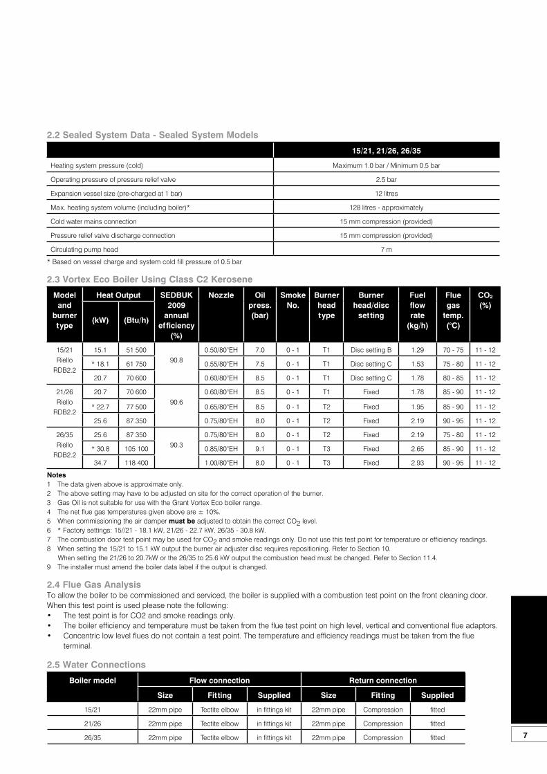
2.2 Sealed System Data - Sealed System Models
15/21, 21/26, 26/35
Heating system pressure (cold) Maximum 1.0 bar / Minimum 0.5 bar
Operating pressure of pressure relief valve 2.5 bar
Expansion vessel size (pre-charged at 1 bar) 12 litres
Max. heating system volume (including boiler)* 128 litres - approximately
Cold water mains connection 15 mm compression (provided)
Pressure relief valve discharge connection 15 mm compression (provided)
Circulating pump head 7 m
* Based on vessel charge and system cold fill pressure of 0.5 bar
2.3 Vortex Eco Boiler Using Class C2 Kerosene
Model and
burner type
Heat Output SEDBUK 2009
annualefficiency
(%)
Nozzle Oil press. (bar)
Smoke No.
Burner head type
Burner head/disc
setting
Fuel flow rate
(kg/h)
Flue gas
temp. (°C)
CO²(%)
(kW) (Btu/h)
15/21Riello
RDB2.2
15.1 51 50090.8
0.50/80°EH 7.0 0 - 1 T1 Disc setting B 1.29 70 - 75 11 - 12
* 18.1 61 750 0.55/80°EH 7.5 0 - 1 T1 Disc setting C 1.53 75 - 80 11 - 12
20.7 70 600 0.60/80°EH 8.5 0 - 1 T1 Disc setting C 1.78 80 - 85 11 - 12
21/26Riello
RDB2.2
20.7 70 60090.6
0.60/80°EH 8.5 0 - 1 T1 Fixed 1.78 85 - 90 11 - 12
* 22.7 77 500 0.65/80°EH 8.5 0 - 1 T2 Fixed 1.95 85 - 90 11 - 12
25.6 87 350 0.75/80°EH 8.0 0 - 1 T2 Fixed 2.19 90 - 95 11 - 12
26/35Riello
RDB2.2
25.6 87 35090.3
0.75/80°EH 8.0 0 - 1 T2 Fixed 2.19 75 - 80 11 - 12
* 30.8 105 100 0.85/80°EH 9.1 0 - 1 T3 Fixed 2.65 85 - 90 11 - 12
34.7 118 400 1.00/80°EH 8.0 0 - 1 T3 Fixed 2.93 90 - 95 11 - 12
Notes1 The data given above is approximate only.2 The above setting may have to be adjusted on site for the correct operation of the burner.3 Gas Oil is not suitable for use with the Grant Vortex Eco boiler range.4 The net flue gas temperatures given above are ± 10%.5 When commissioning the air damper must be adjusted to obtain the correct CO2 level.6 * Factory settings: 15//21 - 18.1 kW, 21/26 - 22.7 kW, 26/35 - 30.8 kW.7 The combustion door test point may be used for CO2 and smoke readings only. Do not use this test point for temperature or efficiency readings.8 When setting the 15/21 to 15.1 kW output the burner air adjuster disc requires repositioning. Refer to Section 10. When setting the 21/26 to 20.7kW or the 26/35 to 25.6 kW output the combustion head must be changed. Refer to Section 11.4.9 The installer must amend the boiler data label if the output is changed.
2.4 Flue Gas AnalysisTo allow the boiler to be commissioned and serviced, the boiler is supplied with a combustion test point on the front cleaning door. When this test point is used please note the following:• The test point is for CO2 and smoke readings only.• The boiler efficiency and temperature must be taken from the flue test point on high level, vertical and conventional flue adaptors.• Concentric low level flues do not contain a test point. The temperature and efficiency readings must be taken from the flue
terminal.
2.5 Water Connections
Boiler model Flow connection Return connection
Size Fitting Supplied Size Fitting Supplied
15/21 22mm pipe Tectite elbow in fittings kit 22mm pipe Compression fitted
21/26 22mm pipe Tectite elbow in fittings kit 22mm pipe Compression fitted
26/35 22mm pipe Tectite elbow in fittings kit 22mm pipe Compression fitted
8
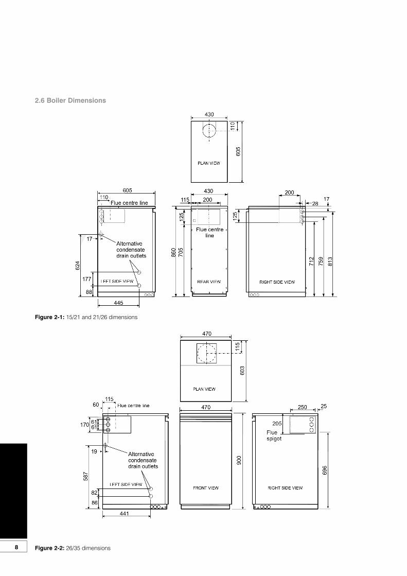
Figure 2-1: 15/21 and 21/26 dimensions
2.6 Boiler Dimensions
Figure 2-2: 26/35 dimensions
9
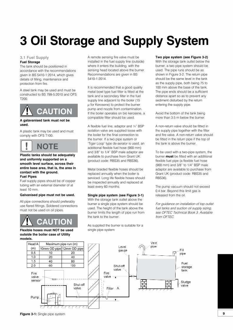
3.1 Fuel SupplyFuel StorageThe tank should be positioned in accordance with the recommendations given in BS 5410-1:2014, which gives details of filling, maintenance and protection from fire.
A steel tank may be used and must be constructed to BS 799-5:2010 and OFS T200.
A galavanised tank must not be used.
A plastic tank may be used and must comply with OFS T100.
Plastic tanks should be adequately and uniformly supported on a smooth level surface, across their entire base area, that is, the area in contact with the ground.Fuel PipesFuel supply pipes should be of coppertubing with an external diameter of at least 10 mm.
Galvanised pipe must not be used.
All pipe connections should preferably use flared fittings. Soldered connectionsmust not be used on oil pipes.
Flexible hoses must NOT be usedoutside the boiler case of Utility models.
3 Oil Storage and Supply SystemA remote sensing fire valve must beinstalled in the fuel supply line (outside)where it enters the building, with thesensing head located above the burner.Recommendations are given in BS 5410-1:2014.
It is recommended that a good quality metal bowl type fuel filter is fitted at the tank and a secondary filter in the fuel supply line adjacent to the boiler (15 µ for Kerosene) to protect the burner pump and nozzle from contamination.If the boiler operates on bio kerosene, a compatible filter should be used.
A flexible fuel line, adaptor and ¼” BSPisolation valve are supplied loose withthe boiler for the final connection tothe burner. If a two pipe system or‘Tiger Loop’ type de-aerator is used, anadditional flexible fuel hose (900 mm)and 3/8” to 1/4” BSP male adaptor areavailable to purchase from Grant UK (product code: RBS35 and RBS36).
Metal braided flexible hoses should bereplaced annually when the boiler isserviced. Long life flexible hoses shouldbe inspected annually and replaced atleast every 60 months.
Single pipe system (see Figure 3-1)With the storage tank outlet above theburner a single pipe system should beused. The height of the tank above theburner limits the length of pipe run fromthe tank to the burner.
As supplied the burner is suitable for asingle pipe system
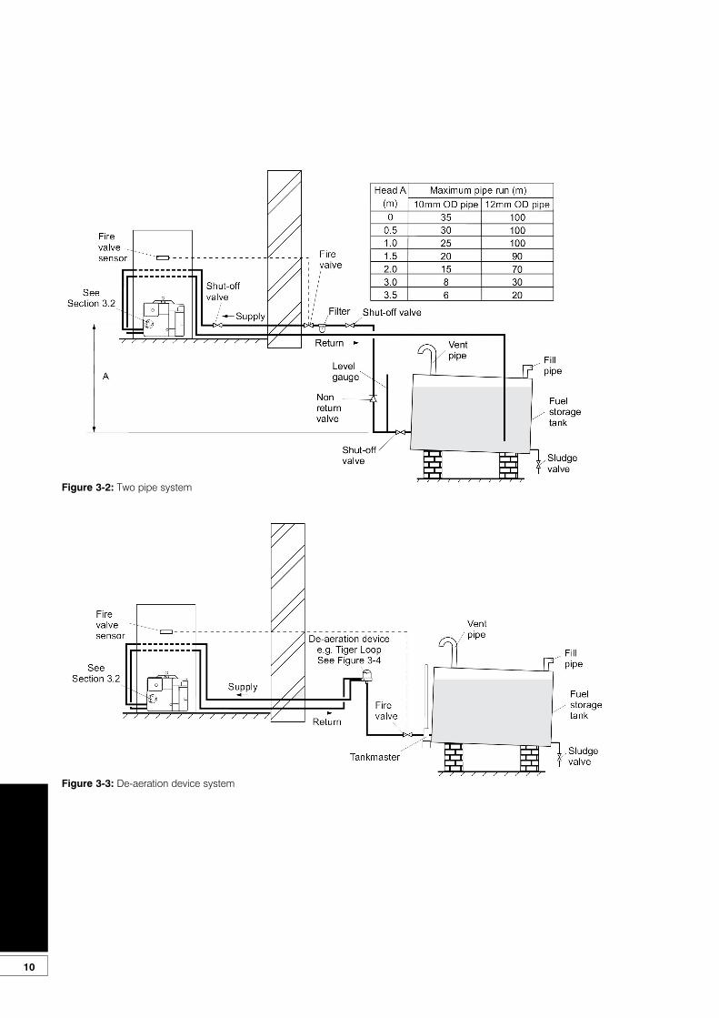
Two pipe system (see Figure 3-2)With the storage tank outlet below theburner, a two pipe system should beused. The pipe runs should be as shown in Figure 3-2. The return pipe should be the same level in the tank as the supply pipe, both being 75 to 100 mm above the base of the tank. The pipe ends should be a sufficient distance apart so as to prevent any sediment disturbed by the return entering the supply pipe.
Avoid the bottom of the tank being more than 3.5 m below the burner.
A non-return valve should be fitted in the supply pipe together with the filter and fire valve. A non-return valve should be fitted in the return pipe if the top of the tank is above the burner.
To be used with a two-pipe system, theburner must be fitted with an additionalflexible fuel pipe (a flexible fuel hose (900 mm) and 3/8” to 1/4” BSP male adaptor are available to purchase from Grant UK (product code: RBS35 and RBS36).
The pump vacuum should not exceed0.4 bar. Beyond this limit gas is released from the oil.
For guidance on installation of top outletfuel tanks and suction oil supply sizing,see OFTEC Technical Book 3. Availablefrom OFTEC.
! CAUTION
! NOTE
! CAUTION
Figure 3-1: Single pipe system
10
Figure 3-2: Two pipe system
Figure 3-3: De-aeration device system
11
Tiger Loop system -(See Figures 3-3 and 3-4)When the storage tank outlet is belowthe burner, an alternative to a two pipesystem can be achieved using a ‘TigerLoop’ type oil de-aerator. This effectively removes the air from the oil supply on a single pipe lift.
The de-aerator is connected close to the boiler as a two pipe system (omitting the non-return valve) as shown in Figure 3-3.Refer to the manufacturers instructionssupplied with the de-aerator.
The de-aerator must be mountedvertically. See Figure 3-3 and 3-4.
To prevent any possibility of fuelfumes entering the building, thede-aerator must be fitted outside inaccordance with BS 5410-1:2014.
To be used with a de-aerator, the burner must be fitted with an additional flexible fuel hose (a flexible fuel hose (900 mm) and 3/8” to 1/4” BSP male adaptor are available to purchase from Grant UK (product code: RBS35 and RBS36).
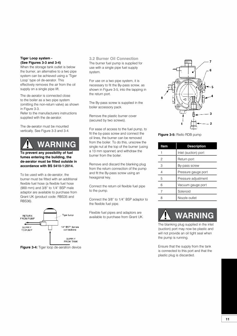
3.2 Burner Oil ConnectionThe burner fuel pump is supplied for use with a single pipe fuel supply system.
For use on a two pipe system, it isnecessary to fit the By-pass screw, asshown in Figure 3-5, into the tapping inthe return port.
The By-pass screw is supplied in theboiler accessory pack.
Remove the plastic burner cover(secured by two screws).
For ease of access to the fuel pump, tofit the by-pass screw and connect the oil lines, the burner can be removed from the boiler. To do this, unscrew the single nut at the top of the burner (using a 13 mm spanner) and withdraw the burner from the boiler.
Remove and discard the blanking plugfrom the return connection of the pumpand fit the By-pass screw using anhexagonal key.
Connect the return oil flexible fuel pipe to the pump.
Connect the 3/8” to 1/4” BSP adaptor tothe flexible fuel pipe.
Flexible fuel pipes and adaptors areavailable to purchase from Grant UK.
Item Description
1 Inlet (suction) port
2 Return port
3 By-pass screw
4 Pressure gauge port
5 Pressure adjustment
6 Vacuum gauge port
7 Solenoid
8 Nozzle outlet
The blanking plug supplied in the inlet(suction) port may now be plastic andwill not provide an oil tight seal when the pump is running.
Ensure that the supply from the tankis connected to this port and that theplastic plug is discarded.
! WARNING
Figure 3-4: Tiger loop de-aeration device
Figure 3-5: Riello RDB pump
! WARNING
12
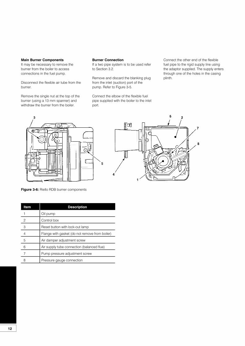
Main Burner ComponentsIt may be necessary to remove theburner from the boiler to accessconnections in the fuel pump.
Disconnect the flexible air tube from theburner.
Remove the single nut at the top of theburner (using a 13 mm spanner) andwithdraw the burner from the boiler.
Item Description
1 Oil pump
2 Control box
3 Reset button with lock-out lamp
4 Flange with gasket (do not remove from boiler)
5 Air damper adjustment screw
6 Air supply tube connection (balanced flue)
7 Pump pressure adjustment screw
8 Pressure gauge connection
Burner ConnectionIf a two pipe system is to be used referto Section 3.2.
Remove and discard the blanking plugfrom the inlet (suction) port of the pump. Refer to Figure 3-5.
Connect the elbow of the flexible fuelpipe supplied with the boiler to the inletport.
Connect the other end of the flexiblefuel pipe to the rigid supply line usingthe adaptor supplied. The supply entersthrough one of the holes in the casingplinth.
Figure 3-6: Riello RDB burner components
13
4.1 IntroductionEco Utility boilers are supplied fullyassembled in a carton.
4.2 Boiler locationThe boiler must stand on a firm and level surface. The boiler base temperature is less than 50°C. No special hearth is required.
Sufficient clearance must be allowedat the front of the boiler to remove theburner and baffles for servicing.
Once the boiler has been installed, apermanent worktop may be fitted overit as access to the top of the boiler is nolonger required after installation.
If a sealed system kit is fitted - Aremovable section of worktop abovethe boiler is required to provideaccess for servicing.
4.3 Preparation for Installation1. Carefully remove the packaging
from the boiler and remove it from the transit pallet.
2. Pull the front panel forward at the top to disengage the fixing clips then lift it up and off the boiler. Remove the literature packs. Give the User Information pack to the householder.
3. Lift off the case top panel(s) and remove the water connecting fittings.
4.4 Installing the Boiler1. Having decided upon the position
of the boiler and type of flue, prepare the wall as described in Section 9. Ensure that the flue terminal position complies with the necessary clearances.
2. Make the water connections as described in Section 5. If access will be restricted, make any connections to the boiler before placing it in its final position. Refer to Section 7 if the boiler is to be used on a sealed system.
3. Ensure the requirements are met for the disposal of condensate as described in Section 6.
4. Connect the power supply as described in Section 8.
5. Connect the flue and ensure there is an adequate air supply as described in Section 9.
4.5 Regulations ComplianceInstallation of a Grant VORTEX Eco boiler must be in accordance with the following recommendations:-• Building Regulations for England
and Wales, and the Building Standards for Scotland issued by the Department of the Environment and any local Byelaws which you must check with the local authority for the area.
• Model and local Water Undertaking Byelaws.
• Applicable Control of Pollution Regulations.
• The following OFTEC requirements:-
- OFS T100 Polythene oil storage tanks for distillate fuels. - OFS T200 Fuel oil storage tanks and tank bunds for use with distillate fuels, lubrication oils and waste oils.
Further information may be obtained from the OFTEC Technical Book 3 (Installation requirements for oil storage tanks) and OFTEC Technical Book 4 (Installation requirements for oil fired boilers).
The installation should also be inaccordance with the latest edition ofthe following British Standard Codes ofPractice:-• BS 715 Metal flue pipes, fittings,
terminals and accessories.• BS 799:5 Oil storage tanks.• BS 1181 Clay flue linings and flue
terminals.• BS 4543:3 Factory made insulated
chimneys for oil fired appliances.• BS 5410:1 Code of Practice for oil
firing appliances.• BS 5449 Forced circulation hot
water systems.• BS 7593 Code of Practice for
treatment of water in heating systems.
• BS 7671 Requirements for electrical installations, IET Wiring Regulations.
4 Boiler Installation Information
! NOTE
! NOTEIf using a balanced flue system - Install the balanced flue system before connecting the heating system pipework to the boiler. Once the flue system is fitted then complete the water connections and fill the heating system.
! NOTEFailure to install and commissionappliances correctly may invalidatethe boiler guarantee.
! WARNINGBefore starting any work on theboiler, or fuel supply please read the health and safety information given in Section 14.
14
4.6 CompletionPlease ensure that the OFTEC CD/10 installation completion report (provided with the boiler) is completed in full.
Leave the top copy with the User.
Retain the carbon copy.
Ensure that the User Information pack (supplied with the boiler) is handed over to the Householder.
4.7 Before you CommissionTo avoid the danger of dirt and foreign matter entering the boiler the complete heating system should be thoroughly flushed out - before the boiler is connected and then again after the system has been heated and is still hot.This is especially important where the boiler is used on an old system.
For optimum performance after installation, this boiler and its associated heating system must be flushed in accordance with the guidelines given in BS 7593:2006 ‘Treatment of water in domestic hot water central heating systems’.
This must involve the use of a proprietary cleaner, such as BetzDearborn’s Sentinel X300 or X400, or Fernox Restorer. Full instructions are supplied with the products, but for more details of BetzDearborn’s products, view the website www.sentinel-solutions.net and for more details of Fernox products view the website www.fernox.com.
For long term protection against corrosion and scale, after flushing, it is recommended that an inhibitor such as Betzdearborn’s Sentinel X100 or Fernox MB-1 is dosed in accordance with the guidelines given in BS 7593:2006.
Failure to implement these guidelines will invalidate the guarantee.
4.8 Heating System DesignConsiderationsTo achieve the maximum efficiencypossible from the Grant VORTEX Proboiler, the heating system should bedesigned to the following parameters:
Radiators:-• Flow temperature 70°C• Return temperature 50°C• Differential 20°C
Underfloor:-• Flow temperature 50°C• Return temperature 40°C• Differential 10°C
Size radiators with a mean watertemperature of 60°C.
Design system controls with programmable room thermostats or use weather compensating controls to maintain return temperatures below 55°C.
The use of a pipe thermostat isrecommended to control the returntemperature when using weathercompensating controls.
Refer to Section 2.5 for the size and type of the connections and Section 5 for the position of the connections.
4.9 Underfloor Heating SystemsIn underfloor systems it is essentialthat the return temperature must bemaintained above 40°C to preventinternal corrosion of the boiler waterjacket.
4.10 Pipework MaterialsGrant boilers are compatible with bothcopper and plastic pipe. Where plasticpipe is used it must be of the oxygenbarrier type and be of the correctclass (to BS 7291-1:2010) for theapplication concerned.
4.11 Sealed SystemsIf plastic pipe is to be used, the installermust check with the plastic pipemanufacturer that the pipe to be usedis suitable for the temperature andpressures concerned.
Plastic pipe must be Class S toBS 7291-1:2010.
4.12 Underfloor PipeworkPlastic pipe may be used on Underfloorsystems where the plastic pipe is fittedafter the thermostatic mixing valve.Copper tube must be used for at leastthe first metre of flow and return primarypipework between the boiler and theunderfloor mixing/blending valves.
! NOTEThe boiler should not be allowed tooperate with return temperatures ofless than 40°C when the system is up to operating temperature.
! WARNINGThe first metre of pipework connected to both the heating flow and return connections of the boiler must be made in copper on all types of system - sealed or open-vented.
! WARNINGThe system must incorporate a low pressure switch to shut off power tothe boiler if the system pressure drops below 0.2 bar. A suitable low pressure switch kit is available to purchase from Grant UK (product code: MPCBS62.
15
5 Pipe Connections
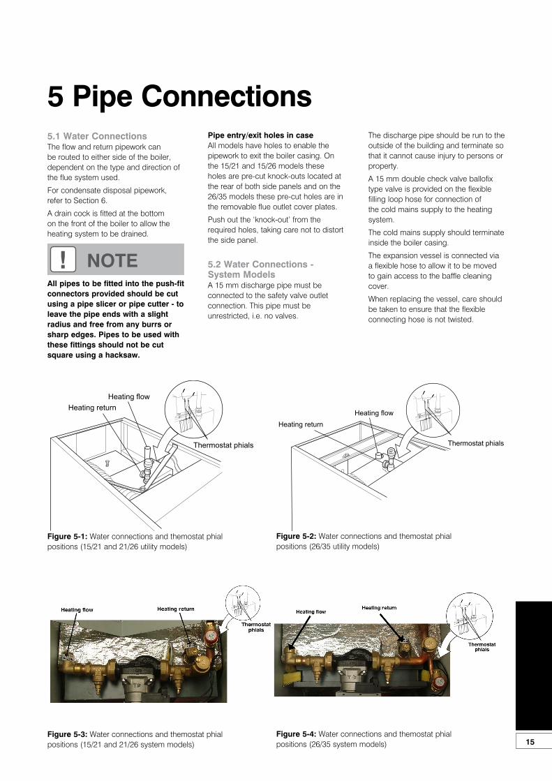
Heating flowHeating return
Thermostat phials
The discharge pipe should be run to the outside of the building and terminate so that it cannot cause injury to persons or property.
A 15 mm double check valve ballofix type valve is provided on the flexible filling loop hose for connection of the cold mains supply to the heating system.
The cold mains supply should terminate inside the boiler casing.
The expansion vessel is connected via a flexible hose to allow it to be moved to gain access to the baffle cleaning cover.
When replacing the vessel, care should be taken to ensure that the flexible connecting hose is not twisted.
! NOTEAll pipes to be fitted into the push-fitconnectors provided should be cutusing a pipe slicer or pipe cutter - toleave the pipe ends with a slightradius and free from any burrs orsharp edges. Pipes to be used withthese fittings should not be cut square using a hacksaw.
Figure 5-3: Water connections and themostat phial positions (15/21 and 21/26 system models)
Pipe entry/exit holes in caseAll models have holes to enable the pipework to exit the boiler casing. On the 15/21 and 15/26 models these holes are pre-cut knock-outs located at the rear of both side panels and on the 26/35 models these pre-cut holes are in the removable flue outlet cover plates.
Push out the ‘knock-out’ from the required holes, taking care not to distort the side panel.
5.2 Water Connections - System ModelsA 15 mm discharge pipe must be connected to the safety valve outlet connection. This pipe must be unrestricted, i.e. no valves.
Figure 5-4: Water connections and themostat phial positions (26/35 system models)
Thermostat phials
Heating returnHeating flow
Thermostat phials
Figure 5-1: Water connections and themostat phial positions (15/21 and 21/26 utility models)
Figure 5-2: Water connections and themostat phial positions (26/35 utility models)
5.1 Water ConnectionsThe flow and return pipework can be routed to either side of the boiler, dependent on the type and direction of the flue system used.
For condensate disposal pipework, refer to Section 6.
A drain cock is fitted at the bottom on the front of the boiler to allow the heating system to be drained.
16
6 Condensate Disposal6.1 General RequirementsWhen in condensing mode the GrantVORTEX Eco boilers produce condensate from the water vapour in the flue gases. This condensate is slightly acidic with a ph value of around 3 (similar to vinegar). Provision must be made for the safe and effective disposal of this condensate.
Condensate can be disposed of using one of the following methods of connection:
Internal connection (preferred option):• into an internal domestic
wastesystem (from kitchen sink, washing machine, etc.)
• directly into the soil stack
External connection:• into an external soil stack• into an external drain or gulley• into a rainwater hopper (that is
part of a combined system where sewer carries both rainwater and foul water)
• purpose made soakaway
All condensate disposal pipes mustbe fitted with a trap - whether they areconnected internally or externally to adomestic waste system/soil stack or runexternally to a gully, hopper or soakaway.
6.2 ConnectionsConnections into a rainwater hopper, external drain or gulley should be terminated inside the hopper/drain/gulley below the grid level but above the water level.
Condensate disposal pipes should notbe connected directly into rainwaterdownpipes or to waste/soil systemsconnected to septic tanks.
Condensate should not be dischargedinto ‘grey water’ systems that re-usewater used in the home (not includingwater from toilets).
It should be noted that connection of acondensate pipe to the drain may be subject to local Building Control requirements.
6.3 PipeworkCondensate disposal pipework must beplastic (plastic waste or overflow pipe issuitable).
Condensate disposal pipes shouldhave a minimum ‘nominal’ diameterof 22 mm (¾”) - e.g. use 21.5 mm ODpolypropylene overflow pipe.
Condensate disposal pipes must befitted with a fall (away from the boiler) ofat least 2.5° (~45 mm fall per metre run).
Condensate disposal pipes shouldbe kept as short as possible and thenumber of bends kept to a minimum.
Pipes should be adequately fixed toprevent sagging, i.e. at no more than 0.5 metre intervals.
6.4 External PipeworkIdeally, external pipework, or pipeworkin unheated areas, should be avoided. Ifunavoidable, external pipework shouldbe kept as short as possible (less than 3 metres) and 32 mm waste pipe used to minimise the risk of ice blocking the pipe in freezing conditions.
The number of bends, fittings and jointson external pipes should be kept to aminimum to reduce the risk of trappingcondensate.
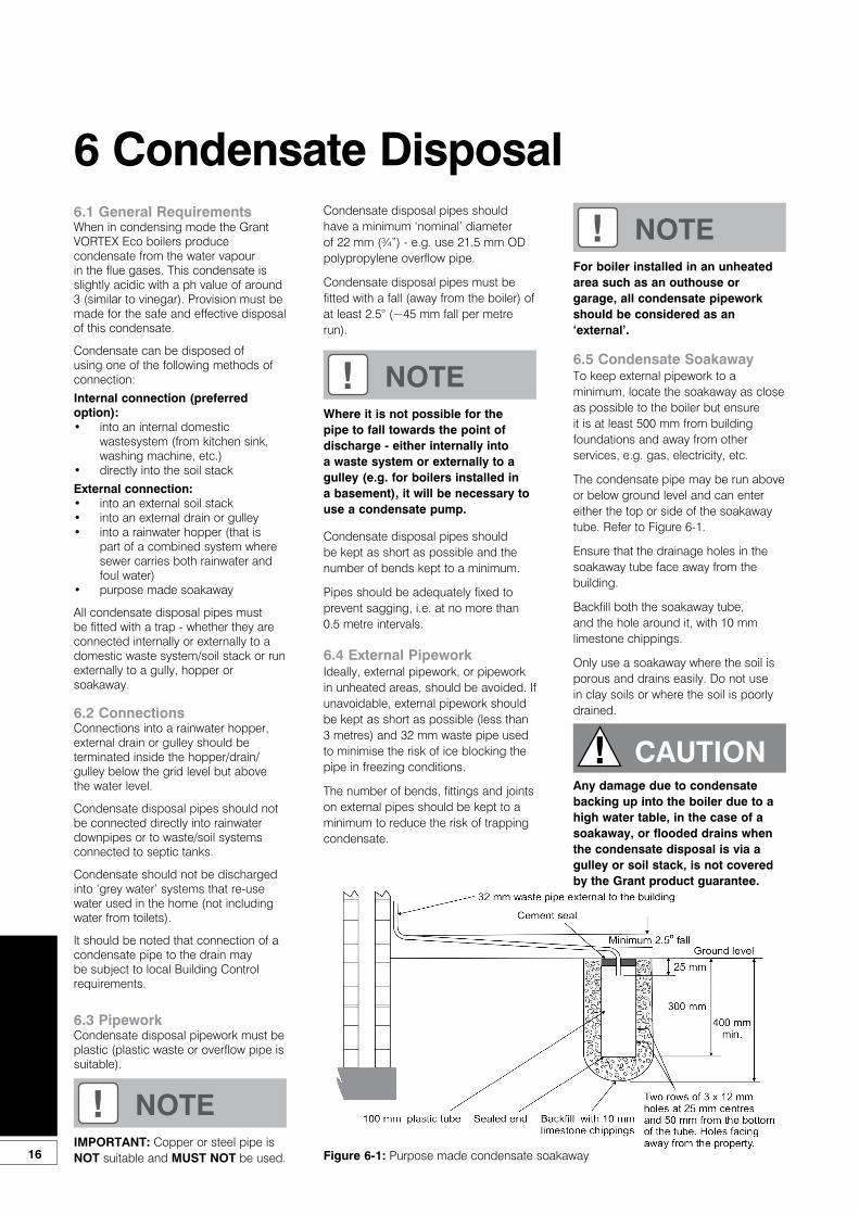
6.5 Condensate SoakawayTo keep external pipework to aminimum, locate the soakaway as closeas possible to the boiler but ensureit is at least 500 mm from buildingfoundations and away from otherservices, e.g. gas, electricity, etc.
The condensate pipe may be run aboveor below ground level and can entereither the top or side of the soakawaytube. Refer to Figure 6-1.
Ensure that the drainage holes in thesoakaway tube face away from the building.
Backfill both the soakaway tube, and the hole around it, with 10 mm limestone chippings.
Only use a soakaway where the soil isporous and drains easily. Do not use in clay soils or where the soil is poorly drained.
! NOTEIMPORTANT: Copper or steel pipe is NOT suitable and MUST NOT be used.
! NOTEFor boiler installed in an unheatedarea such as an outhouse or garage, all condensate pipework should be considered as an ‘external’.
! NOTEWhere it is not possible for the pipe to fall towards the point of discharge - either internally into a waste system or externally to a gulley (e.g. for boilers installed in a basement), it will be necessary to use a condensate pump.
! CAUTION
Figure 6-1: Purpose made condensate soakaway
Any damage due to condensatebacking up into the boiler due to ahigh water table, in the case of asoakaway, or flooded drains when the condensate disposal is via a gulley or soil stack, is not covered by the Grant product guarantee.

17
6.6 Condensate TrapGrant VORTEX Eco boilers are suppliedwith a factory-fitted condensate trap toprovide the required 75 mm water sealin the condensate discharge pipe fromthe boiler.
This trap incorporates a float (which willcreate a seal when the trap is empty) and an overflow warning outlet (fitted with a plastic sealing cap), see Figure 6-2.
The trap is factory-fitted inside the boilercasing (mounted on the inside of the left side panel) in an accessible position to allow for routine maintenance.
A flexible hose connects the outlet ofthe condensing heat exchanger to thetrap inlet. Ensure the straight connectoron the hose is fully pushed onto the ‘tophat’ inlet connector of the trap.
With the trap fitted inside the boilercasing, the sealing cap must be fitted. Ifthe trap is re-located outside the boilerthen the following applies:
If connecting the condensate discharge(either internally or externally) into awaste system or soil stack - the sealingcap must be fitted in the trap outlet.
On external discharge systems to a hopper, gully or soakaway, the sealing cap should be removed from the trap outlet.
If there is any discharge of condensate from the overflow outlet, this could indicate a blockage (possibly due to freezing). Turn off the boiler and investigate the cause. If necessary contact your service engineer for assistance.
Care should be taken when siting thetrap such that the overflow outlet isreadily visible and that any condensateoverflowing from the outlet cannot cause either a hazard to persons or damage to surrounding property or equipment.
The condensate trap outlet is at anangle of 48° below the horizontal. Thisis to automatically give a 3° fall on any‘horizontal’ runs of condensate disposalpipe. Refer to Figure 6-2.
6.7 Condensate Disposal PipeworkThis discharge pipe can exit through theleft side of the boiler through one of twopre-cut ‘knock-outs’ in the lower partof the left casing panel (see to Figures2-1 and 2-2). Push out the ‘knock-out’from the required hole taking care not todistort the side panel.
The outlet of the trap will accept 21.5 mm to 23 mm OD Polypropylene overflow pipe for the condensate discharge pipe.
6.8 Inspection and Cleaning of TrapThe trap must be checked at regularintervals (e.g. on every annual service)and cleaned as necessary to ensure that it is clear and able to operate.
The bottom bowl is sealed to the trap body and cannot be removed.To inspect and clean the trap:1. Disconnect flexible condensate
hose from inlet connector.2. Unscrew the inlet connection nut.3. Remove the inlet connector and
nut from trap.4. Remove trap from bracket.5. Remove float from trap – clean if
necessary.6. Inspect inside of trap and clean as
necessary.7. Re-assemble trap, re-fit to boiler
and re-connect flexible hose. Ensure that hose is fully pushed onto the trap inlet connector.
! NOTEIf required, this condensate trap may be re-located outside the boiler casing. Refer to procedure given in Section 6.9. This procedure must be carried out before the boiler is installed.
Figure 6-2: Condensate trap
! NOTEWhen connecting plastic dischargepipe, ensure that the pipe is fullypushed into the outlet end on theflexible hose to prevent the possibility of leakage.
! CAUTIONFailure to regularly check and cleanthe condensate trap may result indamage to the boiler and will not becovered by the product guarantee.
18
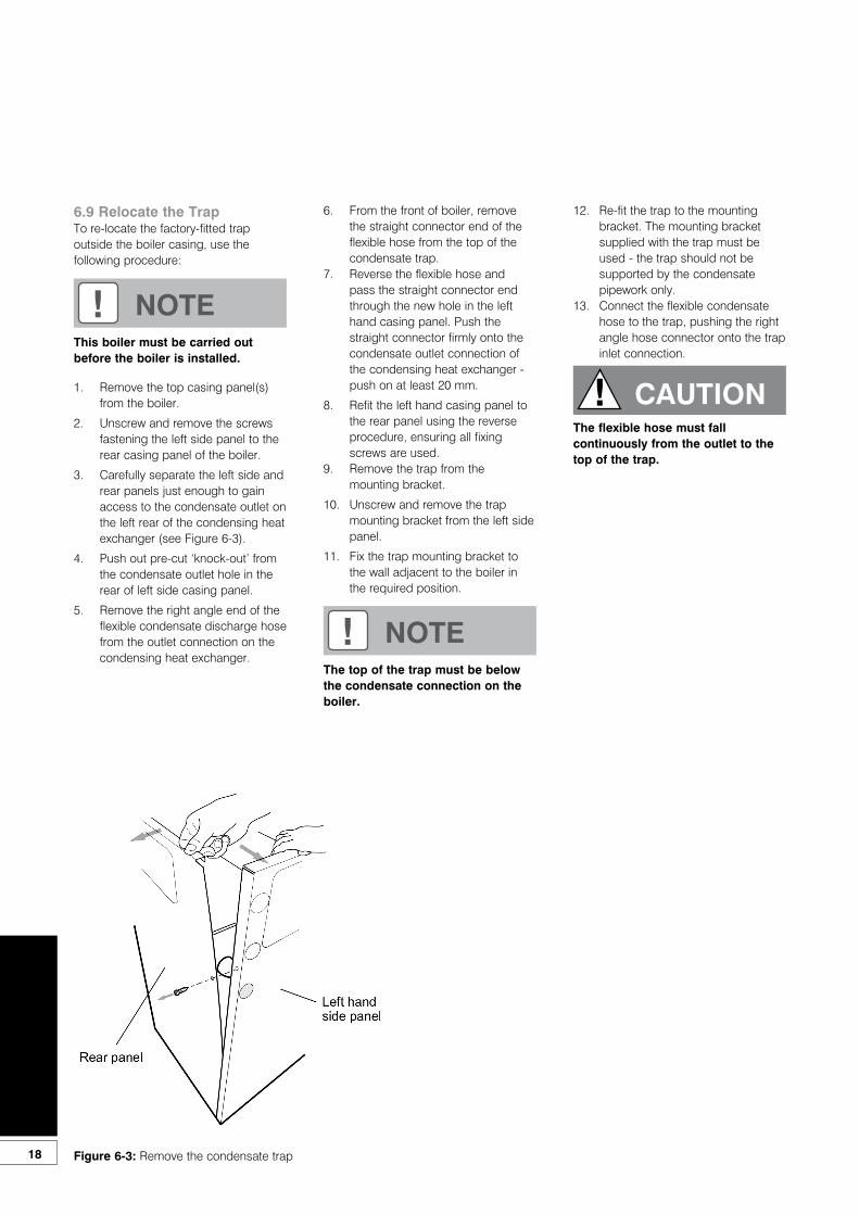
6.9 Relocate the TrapTo re-locate the factory-fitted trapoutside the boiler casing, use thefollowing procedure:
1. Remove the top casing panel(s) from the boiler.
2. Unscrew and remove the screws fastening the left side panel to the rear casing panel of the boiler.
3. Carefully separate the left side and rear panels just enough to gain access to the condensate outlet on the left rear of the condensing heat exchanger (see Figure 6-3).
4. Push out pre-cut ‘knock-out’ from the condensate outlet hole in the rear of left side casing panel.
5. Remove the right angle end of the flexible condensate discharge hose from the outlet connection on the condensing heat exchanger.
! NOTEThis boiler must be carried out before the boiler is installed.
Figure 6-3: Remove the condensate trap
! NOTEThe top of the trap must be below the condensate connection on the boiler.
6. From the front of boiler, remove the straight connector end of the flexible hose from the top of the condensate trap.
7. Reverse the flexible hose and pass the straight connector end through the new hole in the left hand casing panel. Push the straight connector firmly onto the condensate outlet connection of the condensing heat exchanger - push on at least 20 mm.
8. Refit the left hand casing panel to the rear panel using the reverse procedure, ensuring all fixing screws are used.
9. Remove the trap from the mounting bracket.
10. Unscrew and remove the trap mounting bracket from the left side panel.
11. Fix the trap mounting bracket to the wall adjacent to the boiler in the required position.
12. Re-fit the trap to the mounting bracket. The mounting bracket supplied with the trap must be used - the trap should not be supported by the condensate pipework only.
13. Connect the flexible condensate hose to the trap, pushing the right angle hose connector onto the trap inlet connection.
! CAUTIONThe flexible hose must fall continuously from the outlet to the top of the trap.
19
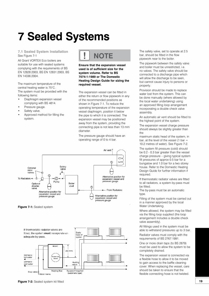
7 Sealed Systems7.1 Sealed System InstallationSee Figure 7-1
All Grant VORTEX Eco boilers aresuitable for use with sealed systemscomplying with the requirements of BS EN 12828:2003, BS EN 12831:2003, BS EN 14336:2004.
The maximum temperature of the central heating water is 75°C.The system must be provided with thefollowing items:• Diaphragm expansion vessel
complying with BS 4814.• Pressure gauge.• Safety valve.• Approved method for filling the
system.
The expansion vessel can be fitted ineither the return or flow pipework in anyof the recommended positions as shown in Figure 7-1. To reduce the operating temperature of the expansion vessel diaphragm, position it below the pipe to which it is connected. The expansion vessel may be positioned away from the system, providing the connecting pipe is not less than 13 mm diameter.
The pressure gauge should have anoperating range of 0 to 4 bar.
The safety valve, set to operate at 2.5bar, should be fitted in the flow pipework near to the boiler.
The pipework between the safety valve and boiler must be unrestricted, i.e. no valves. The safety valve should be connected to a discharge pipe which will allow the discharge to be seen, but cannot cause injury to persons or property.
Provision should be made to replace water lost from the system. This can be done manually (where allowed by the local water undertaking) using an approved filling loop arrangement incorporating a double check valve assembly.
An automatic air vent should be fitted tothe highest point of the system.
The expansion vessel charge pressureshould always be slightly greater than themaximum static head of the system, inbar, at the level of the vessel (1 bar = 10.2 metres of water). See Figure 7-2.
The system fill pressure (cold) shouldbe 0.2 - 0.3 bar greater than the vesselcharge pressure – giving typical system fill pressures of approx 0.5 bar for a bungalow and 1.0 bar for a two storey house. Refer to the Domestic Heating Design Guide for further information if required.
If thermostatic radiator valves are fitted to all radiators, a system by-pass must be fitted.The by-pass must be an automatic type.
Filling of the system must be carried outin a manner approved by the local Water Undertaking.
Where allowed, the system may be filledvia the filling loop supplied (the looparrangement includes a double checkvalve assembly).
All fittings used in the system must beable to withstand pressures up to 3 bar.
Radiator valves must comply with therequirements of BS 2767:1991.
One or more drain taps (to BS 2879)must be used to allow the system to becompletely drained.
The expansion vessel is connected via a flexible hose to allow it to be moved to gain access to the baffle cleaning cover. When replacing the vessel, care should be taken to ensure that the flexible connecting hose is not twisted.
Figure 7-2: Sealed system kit fitted
Figure 7-1: Sealed system
Ensure that the expansion vessel used is of sufficient size for the system volume. Refer to BS 7074:1:1989 or The Domestic Heating Design Guide for sizing the required vessel.
! NOTE

20
7.2 System ModelsAll System models have the following sealed system components factory fitted:• A diaphragm expansion vessel
complying with BS 4814, pre-charged at 1.0 bar. Refer to Section 2.2.
• System pressure gauge, with an operating range of 1 to 4 bar.
• Pressure relief safety valve complying with BS 6759 and set to operate at 2.5 bar.
• Automatic air vent, fitted to the flow pipe of the boiler, ensures the boiler is vented.
• Filling loop. This must be isolated and disconnected after filling the system.
Refer to Section 2.2 for system volumes and BS 7074: for further guidance and for further details of the expansion vessel.
The expansion vessel fitted, is supplied with a charge pressure of 1.0 bar (equivalent to a maximum static head of 10.2 metres). The charge pressure must not be less than the actual static head at the point of connection.
The central heating system volume, using the expansion vessel as supplied, must not exceed the recommended value. Refer to Section 2.2. If the system volume is greater, an extra expansion vessel (complying with BS 4841) must be fitted as close as possible to the central heating return connection on the boiler.
The charge pressure of the extra vessel must be the same as the vessel fitted in the boiler.
Refer to either BS 7074:1:1989 or The Domestic Heating Design Guide for the required total expansion vessel volume for the system concerned.
7.4 Pressure Relief Safety ValveNow the pressure relief safety valve operation must be checked and set. The procedure is as follows:1. Check the operation of the
safety valve by turning the head anticlockwise until it clicks. The click is the safety valve head lifting off its seat allowing water to escape from the system
2. Check that the water is escaping from the system.
3. Continue to fill the system until the pressure gauge indicates between 0.5 and 1.0 bar.
4. Close the fill point valve and check the system for water soundness, rectifying where necessary.
5. Water may be released from the system by manually operating the safety valve until the system design pressure is obtained. The system design pressure (cold) should be between 0.5 bar and 1.0 bar.
The pressure is equivalent to the maximum static head in bar + 0.3 (1 bar = 10.2 metres of water), where the static head is the vertical height from the centre of the expansion vessel to the highest point of the system.
Now close the valves either side of the filling loop and disconnect the loop.
7.3 Fill the Sealed SystemAutomatic air vent(s) are fitted to the top of the boiler (see Figure 7-3). Check that the small cap on the top of each air vent is screwed on fully, then unscrew it one complete turn - the cap remains in this position from now on.
The procedure for filling the sealed system is as follows:1. Only ever fill or add water to the
system when it is cold and the boiler is off. Do not overfill.
2. Ensure that the flexible filling loop supplied with the boiler is connected and that the double check shut off valve connecting it to the water supply is closed.A valve is open when the operating lever is in line with the valve, and closed when it is at right angles to it.
3. Open the fill point valve.4. Gradually open the double check
valve from the water supply until water is heard to flow.
5. When the white needle of the pressure gauge is between 0.5 and 1.0 bar, close the valve.
6. Vent each radiator in turn, starting with the lowest one in the system, to remove air.
7. Continue to fill the system until the pressure gauge indicates between 0.5 and 1.0 bar. Close the fill point valve.
8. Repeat steps 4 and 5 as required.9. Close the fill point and double
check valves either side of the filling loop and disconnect the loop.
! CAUTIONDo not pressurise the vessel above 1.5 bar.
! NOTEThe air pressure in the vessel must be checked annually.
! NOTEThe air charge pressure may be checked using a tyre pressure gauge on the expansion vessel Schraeder valve. The vessel may be re-pressurised using a suitable pump. When checking the airpressure the water in the heating system must be cold and the system pressure reduced to zero.
21
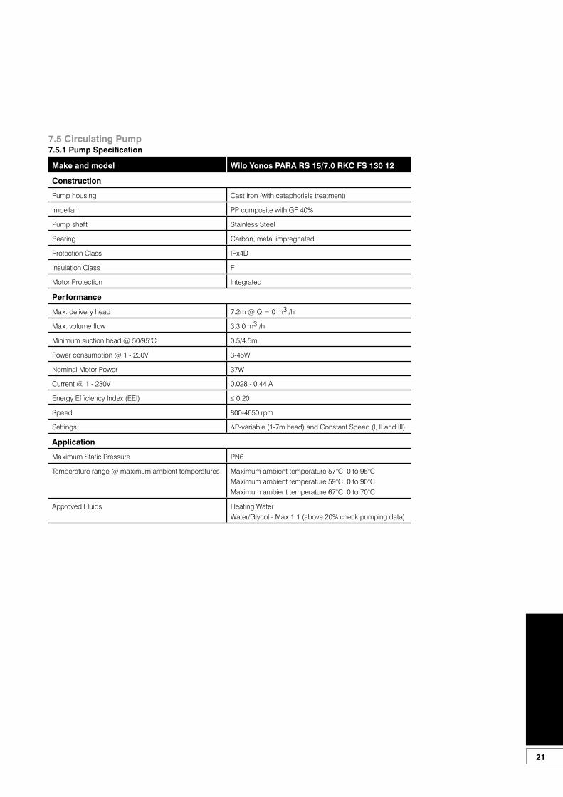
7.5 Circulating Pump7.5.1 Pump Specification
Make and model Wilo Yonos PARA RS 15/7.0 RKC FS 130 12
Construction
Pump housing Cast iron (with cataphorisis treatment)
Impellar PP composite with GF 40%
Pump shaft Stainless Steel
Bearing Carbon, metal impregnated
Protection Class IPx4D
Insulation Class F
Motor Protection Integrated
Performance
Max. delivery head 7.2m @ Q = 0 m3 /h
Max. volume flow 3.3 0 m3 /h
Minimum suction head @ 50/95°C 0.5/4.5m
Power consumption @ 1 - 230V 3-45W
Nominal Motor Power 37W
Current @ 1 - 230V 0.028 - 0.44 A
Energy Efficiency Index (EEI) ≤ 0.20
Speed 800-4650 rpm
Settings ∆P-variable (1-7m head) and Constant Speed (I, II and III)
Application
Maximum Static Pressure PN6
Temperature range @ maximum ambient temperatures Maximum ambient temperature 57°C: 0 to 95°CMaximum ambient temperature 59°C: 0 to 90°CMaximum ambient temperature 67°C: 0 to 70°C
Approved Fluids Heating WaterWater/Glycol - Max 1:1 (above 20% check pumping data)
7.5.2 Pump Control PanelWilo Yonos PARA RKC circulating pumps have two possible setting modes:• Constant speed with three pump
speed settings (I, II and III)• Variable pressure (∆p-v) with pump
head adjustable between 1 and 7m head
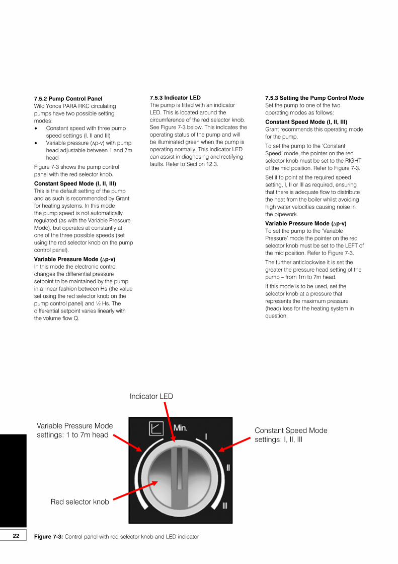
Figure 7-3 shows the pump control panel with the red selector knob.
Constant Speed Mode (I, II, III)This is the default setting of the pump and as such is recommended by Grant for heating systems. In this mode the pump speed is not automatically regulated (as with the Variable Pressure Mode), but operates at constantly at one of the three possible speeds (set using the red selector knob on the pump control panel).
Variable Pressure Mode (∆p-v)In this mode the electronic control changes the differential pressure setpoint to be maintained by the pump in a linear fashion between Hs (the value set using the red selector knob on the pump control panel) and ½ Hs. The differential setpoint varies linearly with the volume flow Q.
7.5.3 Indicator LEDThe pump is fitted with an indicator LED. This is located around the circumference of the red selector knob. See Figure 7-3 below. This indicates the operating status of the pump and will be illuminated green when the pump is operating normally. This indicator LED can assist in diagnosing and rectifying faults. Refer to Section 12.3.
7.5.3 Setting the Pump Control ModeSet the pump to one of the two operating modes as follows:
Constant Speed Mode (I, II, III)Grant recommends this operating mode for the pump.
To set the pump to the ‘Constant Speed’ mode, the pointer on the red selector knob must be set to the RIGHT of the mid position. Refer to Figure 7-3.
Set it to point at the required speed setting, I, II or III as required, ensuring that there is adequate flow to distribute the heat from the boiler whilst avoiding high water velocities causing noise in the pipework.
Variable Pressure Mode (∆p-v)To set the pump to the ‘Variable Pressure’ mode the pointer on the red selector knob must be set to the LEFT of the mid position. Refer to Figure 7-3.
The further anticlockwise it is set the greater the pressure head setting of the pump – from 1m to 7m head.
If this mode is to be used, set the selector knob at a pressure that represents the maximum pressure (head) loss for the heating system in question.
Variable Pressure Mode settings: 1 to 7m head
Indicator LED
Constant Speed Mode settings: I, II, III
Red selector knob
Figure 7-3: Control panel with red selector knob and LED indicator22

23
8 ElectricalThe VORTEX Eco boiler requires a230/240 V ~ 50 Hz supply. It must beprotected by a 5 Amp fuse.
Refer to Figures 8-1 and 8-2 for typicalcontrol system wiring diagrams. Refer toFigure 8-3 for control panel wiring diagram.
The supply must be fused at 5 Ampand there must only be one commonisolator for the boiler and control system, providing complete electrical isolation.
A fused double pole switch or afused three pin plug and shutteredoutlet socket should be used for theconnection.
The power supply cable should be atleast 0.75 mm² PVC as specified in BS6500, Table 16.
All the wiring and supplementary earthbonding external to the boiler must be in accordance with the current IET. Wiring Regulations.
Any room thermostat or frost thermostatused must be suitable for use on mainsvoltage.
In the event of an electrical fault afterinstallation of the boiler, the followingelectrical system checks must be carried out:• Short circuit• Polarity• Earth continuity• Resistance to earth
! WARNINGThe VORTEX Eco boiler containselectrical switching equipment andmust be earthed.
8.1 Connecting the Power SupplyIt is recommend that the boiler should be connected to a switched mains power supply from a programmer or control system. A three core cable is required to connect the boiler terminal block to the live supply. Refer to Figure 8-1 and 8-2 for typical control system wiring diagrams.
The procedure is:1. Lift off the boiler case top panel, if
it has not already been removed.2. Remove the top of the control
panel and open the cable clamp. Route the supply cable through the hole in the rear panel (using the grommet supplied) up to the control panel, pass it through the cable clamp and connect to the boiler terminal block as follows:-Brown to live (terminal 1)Blue to mains neutral (terminal 2)Green/Yellow to mains earth(terminal 3)
3. Secure the cable in the cable clamp.
4. Place the wiring cover in position over the terminal block, taking care not to trap any wires and secure in position with the two M4 screws provided.
5. Ensure that all external wiring is adequately supported.
Do not switch on the electricity supply at this stage.
! NOTEEnsure that the route and lengthof the supply cable is such that theboiler front cover plate can be easilyremoved without disconnecting thesupply cable from the terminal block.
8.2 Frost ProtectionFor additional protection of either theentire heating system, or the boiler andlocalised pipework, it is recommendedthat a frost thermostat be installed.
Refer to Figures 8-1 to 8-3 (asappropriate) for connection details.
To protect the heating system, thefrost thermostat should be sited withinthe house in such a place that it candetect any rise and fall in the ambientair temperature, i.e. in a room with aradiator.
Where the frost thermostat is installedoutside the house (to protect a boilerinstalled in an external boiler room orgarage) or in an attic, it is recommended that it be used in conjunction with a pipe thermostat to avoid unnecessary and wasteful overheating of the property. The pipe thermostat should be located on the boiler return pipe, and set to operate at 25°C.
Refer to Figures 8-1 to 8-3 (asappropriate) for connection details.

24
8.3 Control System Wiring Diagrams
Figure 8-1: CH and HW controlled by two 2-port zone valves
Figure 8-2: CH and HW controlled by 3-port mid position zone valve
2-Port Zone Valve
MotorRoomStat
2 1 3
N
Grant 2-ChannelWall Mounted
Programmer ESKIT
240V50HZ
L N E
5A
2-Port Zone Valve
Motor
1 2 3 4 5 6 7 8 9 10
HTG
HW
L 1 2 3 4
FrostThermostat
Pipe Stat(If fitted)
Pump(Utility Models)
WiringCentre
GreyGrey
OrangeOrange
BrownBlue
Green/Yellow
Green/Yellow
BrownBlue
BrownBlue
Green/Yellow
BlueGreen/Yellow
BrownLink
OFF OFF ON ONHW HT HW HT
CylinderStat
1C 2
ENL
1
L N E
2 3 4
L N E E N L
5 6 7 8 9
BoilerTerminalBlock
Supply toBurner
ENL
BlueGreen/Yellow
Brown ENL
Pump(Utility SystemModels Only)
CylinderStat
N
Grant 2-ChannelWall Mounted
Programmer ESKIT
240V50HZ
L N E
5A
1 2 3 4 5 6 7 8 9 10
L 1 2 3 4
FrostThermostat
Pipe Stat(If fitted)
WiringCentre
GreyOrange
Green/Yellow
BrownBlue
Link
OFF OFF ON ONHW HT HW HT
3-Port Mid PositionZone Valve
MotorBlueGreen/Yellow
1C 2
White
Link
13k2W
270k0.25W
RoomStat
2 1 3
BlueGreen/Yellow
Brown
ENL
1
L N E
2 3 4
L N E E N L
5 6 7 8 9
BoilerTerminalBlock
ENL
BlueGreen/Yellow
Brown ENL
Pump(Utility Models)
Supply toBurner
Pump(Utility SystemModels Only)
25
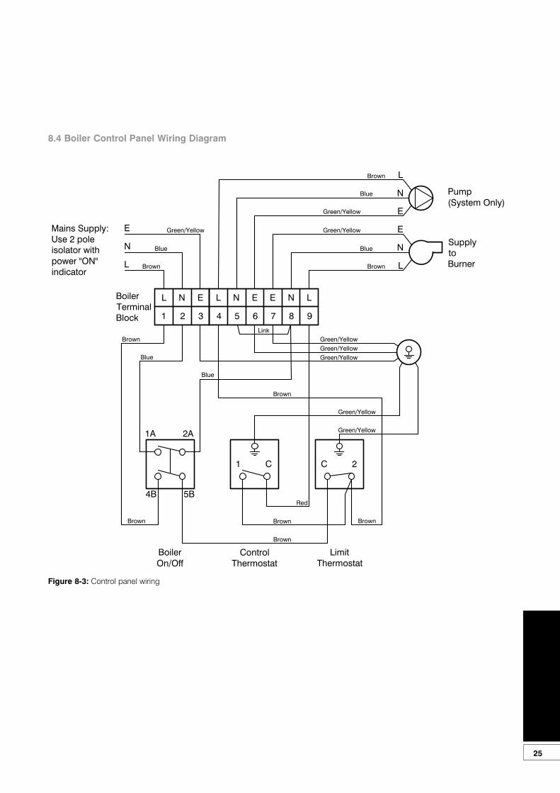
Figure 8-3: Control panel wiring
8.4 Boiler Control Panel Wiring Diagram
1A 2A
4B 5B
1 C C 2
E
N
L
E
N
L
Mains Supply:Use 2 poleisolator withpower "ON"indicator
SupplytoBurner
Green/Yellow
Brown
Blue
Green/Yellow
Brown
Blue
Brown
Blue
Red
Green/Yellow
Green/Yellow
Green/Yellow
Green/Yellow
1
L N E
2 3 4
L N E E N L
5 6 7 8 9
BoilerTerminalBlock
Green/Yellow
Link
Pump(System Only)
Green/Yellow
Brown
Blue
E
N
L
Brown
BrownBrown Brown
Blue
LimitThermostat
BoilerOn/Off
ControlThermostat
Brown
26
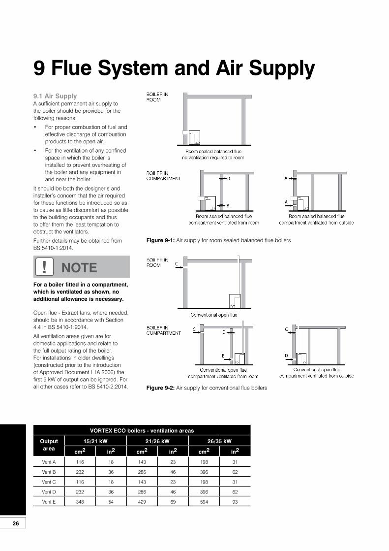
9.1 Air SupplyA sufficient permanent air supply tothe boiler should be provided for thefollowing reasons:
• For proper combustion of fuel and effective discharge of combustion products to the open air.
• For the ventilation of any confined space in which the boiler is installed to prevent overheating of the boiler and any equipment in and near the boiler.
It should be both the designer’s andinstaller’s concern that the air requiredfor these functions be introduced so asto cause as little discomfort as possibleto the building occupants and thusto offer them the least temptation toobstruct the ventilators.
Further details may be obtained from BS 5410-1:2014.
Open flue - Extract fans, where needed,should be in accordance with Section4.4 in BS 5410-1:2014.
All ventilation areas given are fordomestic applications and relate tothe full output rating of the boiler.For installations in older dwellings(constructed prior to the introductionof Approved Document L1A 2006) thefirst 5 kW of output can be ignored. Forall other cases refer to BS 5410-2:2014.
9 Flue System and Air Supply
! NOTEFor a boiler fitted in a compartment,which is ventilated as shown, noadditional allowance is necessary.
Figure 9-1: Air supply for room sealed balanced flue boilers
Figure 9-2: Air supply for conventional flue boilers
VORTEX ECO boilers - ventilation areas
Outputarea
15/21 kW 21/26 kW 26/35 kW
cm2 in2 cm2 in2 cm2 in2
Vent A 116 18 143 23 198 31
Vent B 232 36 286 46 396 62
Vent C 116 18 143 23 198 31
Vent D 232 36 286 46 396 62
Vent E 348 54 429 69 594 93
27
9.2 Conventional Flue Systems
Grant condensing boilers have high operating efficiencies and low flue gas temperatures. Care must be taken to ensure the flue system is suitable for the very low flue gas temperatures and condensate in the flue gases.
Suitable conventional flue systems are available from Grant UK.
The flue must terminate in a down draught free area, i.e. at least 600 mm above the point of exit through the roof or preferably above the ridge level.
The condensate may be allowed to run back into the boiler. A condensate drain at the base of the flue system is not required.
The high level flue terminal must be at least 600 mm from any opening into the building, and 600 mm above any vertical structure or wall less than a horizontal distance of 750 mm from the terminal.
If an existing chimney is to be used, it must be lined with a smooth bore stainless steel liner suitable for use with oil fired condensing boilers. The top and bottom of the annular space must be sealed.
Grant recommends the use of the Grant ‘Orange’ flue system, specifically designed for the VORTEX range of condensing boilers.
The internal flue and liner diameter for all models must be 100 mm (4 in).
The maximum vertical height (from the top of the boiler to the terminal) for the ‘Orange’ system is 19 metres.
If a rigid flue is used externally, it must be of the twin-wall type incorporating seals at all joints, constructed with a stainless steel inner skin and be suitably insulated and weatherproofed. The internal flue diameter for a rigid flue for all models is 100 mm (4 in).
Use the larger ‘200’ size of ‘Green’ system components as listed in Figure 9-9 for the 26/35 model.
Grant recommends the use of the Grant ‘Green’ and ‘Orange’ flue system components for this application. Refer to Section 1.2 for details.
If required, it is possible to use the white painted single-wall straight flue extensions, adjustable extensions and elbows from the Grant ‘Orange’ system for the internal section of the flue system, see Figure 9-4. These components can be fitted between the boiler connector and flue adaptor. The flue adaptor, to which the external twin-wall ‘Green’ flue components are connected, can therefore be situated just before the flue system passes through the wall.
The maximum vertical height (from the top of the boiler to the terminal) for the 100 mm diameter hybrid ‘Green/Yellow’ system is 8 metres.
Grant ‘Green’ twin-wall flue is recommended for externally run flues to reduce the possibility of the condensate freezing in the flue.
No part of any flue system should be made of an asbestos material; aluminium must not be used in any part of the flue.
Only stainless steel flue components should be used.
If the draught conditions are satisfactory, the flue should terminate with a standard cowl.
Refer to the locally applicable Building Regulations, BS 5410-1 and OFTEC Installation Requirements (OFTEC Technical Books 2 and 4) for further guidance on conventional flue systems.
Only use flue systems suitable for oil fired condensing boilers.
Do not use fire cement. The use of high temperature silicone sealants is recommended.
! NOTEUnder no circumstances can GrantVORTEX Eco boilers be installedwith existing flue systems. Only fluesystems and components suitable for wet flues should be used.
Failure to install the correct typeof flue system will invalidate theguarantee.
! NOTEThe Grant Orange system flexiblestainless steel liner is directional. The arrows marked on the liner MUST be pointing vertically upwards, following the direction of the flue gases. Failure to comply with this instruction could leadto a leakage of condensate from the flue liner.
! NOTEAs no flue adaptor is supplied with the boiler, in order to correctly connect the hybrid system, it will be necessary to purchase the Grant CF adaptor kit (product code: CFA15/70).
! NOTEGrant ‘Orange’ system single-wallflue components must not be usedexternally.
! CAUTIONIt is important to ensure that the fluesystem is sealed and that condensate cannot escape. Up to 1.5 l/h of condensate can be produced in a conventional flue system.
! NOTETo comply with the requirements ofthe Building Regulations ApprovedDocument J - conventional flue systems must have a flue data plate. A suitable data plate is supplied with the Grant Orange flue system and should be displayed next to the boiler or flue.
28
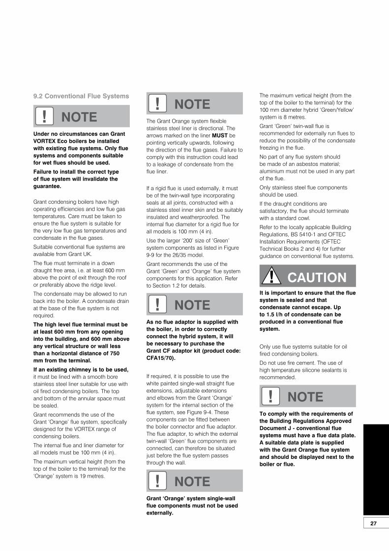
Flue Lining KitsGrant EZ-Fit Flexi Pack conventional flue system (Orange System)
A range of Flexi pack conventional flue lining kits are available from Grant UK. The packs have been specifically produced for Grant VORTEX oil fired condensing boilers.
The pack includes a terminal/top plate/flexi flue adaptor, stainless steel smooth bore flexible flue liner, a rigid to flexi adaptor and a boiler flue connector.
A 100 mm diameter liner is suitable for all models.
ExtensionsA range of white powder coated single wall extensions are available to connect the boiler to the flexible liner.
The nominal diameter of the extensions is 100 mm.
Extensions are supplied with locking bands.
Flue extensions cannot be cut.
Also available are:• An adjustable extension• 45° elbow
Part number Flexi pack (orange system)
GFKIT 6/100 100 mm diameter x 6 metre
GFKIT 8/10 100 mm diameter x 8 metre
GFKIT 10/100 100 mm diameter x 10 metre
GFKIT 11/100 100 mm diameter x 11 metre
GFKIT 12/100 100 mm diameter x 12 metre
GFKIT 14/100 100 mm diameter x 14 metre
GFKIT 16/100 100 mm diameter x 16 metre
Part number Extensions (orange system)
WX 150/100 100 mm diameter x 150 mm
WX 250/100 100 mm diameter x 250 mm
WX 450/100 100 mm diameter x 450 mm
WX 950/100 100 mm diameter x 950 mm
! NOTEThe rigid flue between the boiler and flexible flue liner should incorporate an adjustable section to allow inspection and cleaning of the flue system.
Figure 9-3: Grant Orange flue system in a typical brick chimney
29
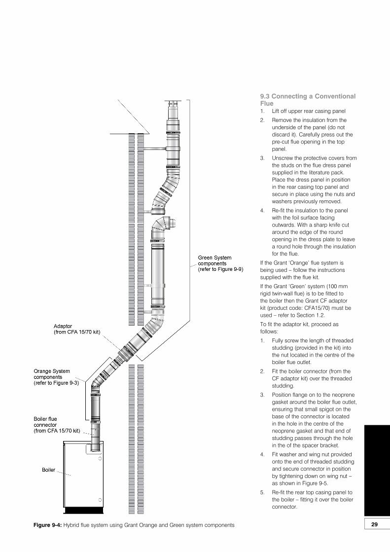
9.3 Connecting a Conventional Flue1. Lift off upper rear casing panel
2. Remove the insulation from the underside of the panel (do not discard it). Carefully press out the pre-cut flue opening in the top panel.
3. Unscrew the protective covers from the studs on the flue dress panel supplied in the literature pack. Place the dress panel in position in the rear casing top panel and secure in place using the nuts and washers previously removed.
4. Re-fit the insulation to the panel with the foil surface facing outwards. With a sharp knife cut around the edge of the round opening in the dress plate to leave a round hole through the insulation for the flue.
If the Grant ‘Orange’ flue system is being used – follow the instructions supplied with the flue kit.
If the Grant ‘Green’ system (100 mm rigid twin-wall flue) is to be fitted to the boiler then the Grant CF adaptor kit (product code: CFA15/70) must be used – refer to Section 1.2.
To fit the adaptor kit, proceed as follows:
1. Fully screw the length of threaded studding (provided in the kit) into the nut located in the centre of the boiler flue outlet.
2. Fit the boiler connector (from the CF adaptor kit) over the threaded studding.
3. Position flange on to the neoprene gasket around the boiler flue outlet, ensuring that small spigot on the base of the connector is located in the hole in the centre of the neoprene gasket and that end of studding passes through the hole in the of the spacer bracket.
4. Fit washer and wing nut provided onto the end of threaded studding and secure connector in position by tightening down on wing nut – as shown in Figure 9-5.
5. Re-fit the rear top casing panel to the boiler – fitting it over the boiler connector.
Figure 9-4: Hybrid flue system using Grant Orange and Green system components

30
6. Fit the flue adaptor (from the adaptor kit) into the boiler connector.
7. Fit the first section of flue into theflue adaptor and secure using theclamp band provided.
8. Assemble the remainder of the fluesystem as required, lubricating theseal on each component beforefitting.
9.4 Balanced Flue SystemApart from a conventional flue, severalbalanced flue options are available foruse with the Grant VORTEX boilers.All are suitable for use with Class C2kerosene.
Low level horizontal balanced flue(Yellow system)Available in Short (for single thickness brick walls) and Standard kits.
Extensions are available which extend the flue by 225 mm, 450 mm or 675 mm.
90° and 45° elbows are also available.
The maximum flue length - from the centre of the boiler flue outlet to the outer face of the wall - is 4 metres (with or without elbows included). No more than 2 x 45° or 1 x 90° elbow should be fitted per system.
The low level balanced flue (Yellow system) is supplied with a stainless steel guard. This must be fitted in all circumstances to prevent objects from entering the flue outlet.
The guard must be fitted centrally over the flue terminal and securely fixed to the wall.
High level (horizontal) balanced flue(White system)The High Level (horizontal) balanced flue (White system) allows the flue to rise vertically within the building before exiting through the wall horizontally.
The maximum flue length - from the top of the boiler flue outlet to the outer face of the wall - is 10 metres for all VORTEX boilers.
The following items are additionally available:• Extensions to extend the flue by
225 mm, 450 mm or 950 mm.• An adjustable extension of 275 to
450 mm.• A 45° elbow - No more than 6 x
45° elbows should be fitted per system.Each elbow reduces the overall maximum length of the system by 1metre.
Figure 9-5: Boiler flue connector
! NOTELubricate the seal on the adaptorusing the lubricant provided beforeattempting to fit the flue adaptor.
! NOTENone of the flue sections in thefollowing system can be cut.
Figure 9-6: Low level balanced flue
Figure 9-7: High level balanced flue

31
Vertical balanced flue(White system)Allows the flue to rise vertically from the boiler to exit through the roof.
The maximum flue length - from the top of the boiler flue outlet to the terminal is 12 metres for all VORTEX boilers.
The following items are additionally available:• Extensions to extend the flue by
225 mm, 450 mm or 950 mm.• An adjustable extension of 275 to
450 mm.• A 45° elbow - No more than 6 x
45° elbows should be fitted per system.
• Each elbow reduces the overall maximum length of the system by 1 metre.
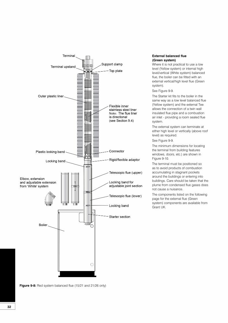
Flexible vertical balanced flue(Red system)This is a flexible vertical balanced flue system (for the 15/21 and 21/26 models only) designed to be fitted inside an existing masonry chimney. See Figure 9-8.
It basically consists of three sections:• Concentric white painted flue pipe
connected to the boiler.• Vertical concentric flexible flue
(flexible stainless steel twin-wall liner inside a stainless steel single-wall liner.
• Terminal assembly for chimney top mounting.
The flue pipe seals are factory fitted and must be lubricated with the lubricant supplied before assembly.The Red system is supplied as a separate kit. Flue extensions and 45° elbows from the White system may be used to extend the flue between the boiler and the flexible section of the system.
The maximum vertical straight length of flue, from the top of the boiler to the top of the terminal, is 20 metres – using no more than four 45° elbows. Deduct 1 metre of straight flue length for every elbow used.
The Grant Red system flexible stainless steel liner is directional. The arrows marked on the liner MUST be pointing vertically upwards, following the direction of the flue gases. Failure to comply with this instruction could lead to a leakage of condensate from the flue liner.
Flue extensions cannot be cut, use adjustable extensions where required.
Two types of locking band are supplied with the kit.
The first type is for connecting flue sections that butt together (two of this type of locking band are supplied).
The second type is to cover the joint on the adjustable (telescopic) section.
There are also two types of stainless steel clamp bands supplied with the kit for fitting the inner and outer stainless steel liners on to the rigid to flex adaptor.
The flue kit includes a black coated terminal with upstand and is designed to be fixed (using the screws provided) to the top of a masonry chimney.
The flue system may be offset using 45° elbows (product code: ELBK2145/90).
No more than a maximum of four elbows should be used per system.
White System Components - Part numbers
Item 15/21 and 21/26 models 26/35 model
High level flue kit - 1.2 metre HLK01 50/90 HLK02 90/200
Vertical flue kit - 3 metre VTK05 50/90 VTK06 90/200
225 mm extension EXTK31 225/90 EXTK32 225/200
450 mm extension EXTK09 450/90 EXTK10 450/200
950 mm extension EXTK11 950/90 EXTK12 950/200
275 - 450 mm adjustable extension EXTK13 ADJ/90 EXTK14 ADJ/200
45° elbow ELBK21 45/90 ELBK22 45/200
Wall bracket BRK29 90 BRK30 200
Pitched roof flashing - aluminium (for VTK05 50/90) VTMF 90Not applicablePitched roof flashing - lead (for VTK05 50/90) VTK25 P90
Flat roof flashing - aluminium (for VTK05 50/90) VTK27 F90
Pitched roof flashing - aluminium (for VTK06 90/200)Not applicable
VTMF 200
Pitched roof flashing - lead (for VTK06 90/200) VTK26 P200
Flat roof flashing - aluminium (for VTK06 90/200) VTK28 F200
! NOTEIf the flexible liners have to pass around an offset inside the chimney deduct 2 metres of straight flue length to compensate for this.
! NOTEThe locking band for the adjustablesection is labelled for easyidentification.
32
External balanced flue(Green system)Where it is not practical to use a low level (Yellow system) or internal high level/vertical (White system) balanced flue, the boiler can be fitted with an external vertical/high level flue (Green system).
See Figure 9-9.
The Starter kit fits to the boiler in the same way as a low level balanced flue (Yellow system) and the external Tee allows the connection of a twin wall insulated flue pipe and a combustion air inlet - providing a room sealed flue system.
The external system can terminate at either high level or vertically (above roof level) as required.
See Figure 9-9.
The minimum dimensions for locating the terminal from building features windows, doors, etc.) are shown in Figure 9-10.
The terminal must be positioned so as to avoid products of combustion accumulating in stagnant pockets around the buildings or entering into buildings. Care should be taken that the plume from condensed flue gases does not cause a nuisance.
The components listed on the following page for the external flue (Green system) components are available from Grant UK.
Figure 9-8: Red system balanced flue (15/21 and 21/26 only)
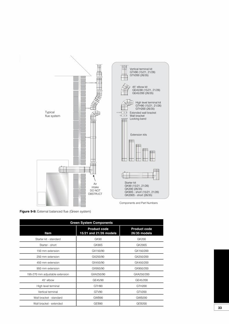
33
Vertical terminal kitGTV90 (15/21, 21/26)GTV200 (26/35)
45° elbow kitGE45/90 (15/21, 21/26)GE45/200 (26/35)
Starter kitGK90 (15/21, 21/26)GK200 (26/35)GK90S - short (15/21, 21/26)GK200S - short (26/35)
High level terminal kitGTH90 (15/21, 21/26)GTH200 (26/35)
Extension kits
Wall bracketExtended wall bracket
Locking band
Airintake
DO NOTOBSTRUCT
Components and Part Numbers
Typicalflue system
Figure 9-9: External balanced flue (Green system)
Green System Components
ItemProduct code
15/21 and 21/26 modelsProduct code26/35 models
Starter kit - standard GK90 GK200
Starter - short GK90S GK200S
150 mm extension GX150/90 GX150/200
250 mm extension GX250/90 GX250/200
450 mm extension GX450/90 GX450/200
950 mm extension GX950/90 GX950/200
195-270 mm adjustable extension GXA250/90 GXA250/200
45° elbow GE45/90 GE45/200
High level terminal GTH90 GTH200
Vertical terminal GTV90 GTV200
Wall bracket - standard GWB90 GWB200
Wall bracket - extended GEB90 GEB200
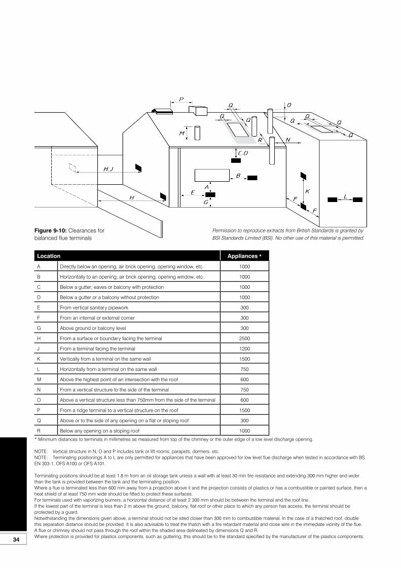
34
Location Appliances *
A Directly below an opening, air brick opening, opening window, etc. 1000
B Horizontally to an opening, air brick opening, opening window, etc. 1000
C Below a gutter, eaves or balcony with protection 1000
D Below a gutter or a balcony without protection 1000
E From vertical sanitary pipework 300
F From an internal or external corner 300
G Above ground or balcony level 300
H From a surface or boundary facing the terminal 2500
J From a terminal facing the terminal 1200
K Vertically from a terminal on the same wall 1500
L Horizontally from a terminal on the same wall 750
M Above the highest point of an intersection with the roof 600
N From a vertical structure to the side of the terminal 750
O Above a vertical structure less than 750mm from the side of the terminal 600
P From a ridge terminal to a vertical structure on the roof 1500
Q Above or to the side of any opening on a flat or sloping roof 300
R Below any opening on a sloping roof 1000
* Minimum distances to terminals in millimetres as measured from top of the chimney or the outer edge of a low level discharge opening.
NOTE: Vertical structure in N, O and P includes tank or lift rooms, parapets, dormers, etc.NOTE: Terminating positionings A to L are only permitted for appliances that have been approved for low level flue discharge when tested in accordance with BS EN 303-1, OFS A100 or OFS A101.
Terminating positions should be at least 1.8 m from an oil storage tank unless a wall with at least 30 min fire resistance and extending 300 mm higher and wider than the tank is provided between the tank and the terminating position.Where a flue is terminated less than 600 mm away from a projection above it and the projection consists of plastics or has a combustible or painted surface, then a heat shield of at least 750 mm wide should be fitted to protect these surfaces.For terminals used with vaporizing burners, a horizontal distance of at least 2 300 mm should be between the terminal and the roof line.If the lowest part of the terminal is less than 2 m above the ground, balcony, flat roof or other place to which any person has access, the terminal should be protected by a guard.Notwithstanding the dimensions given above, a terminal should not be sited closer than 300 mm to combustible material. In the case of a thatched roof, double this separation distance should be provided. It is also advisable to treat the thatch with a fire retardant material and close wire in the immediate vicinity of the flue.A flue or chimney should not pass through the roof within the shaded area delineated by dimensions Q and R.Where protection is provided for plastics components, such as guttering, this should be to the standard specified by the manufacturer of the plastics components.
Figure 9-10: Clearances for balanced flue terminals
Permission to reproduce extracts from British Standards is granted by BSI Standards Limited (BSI). No other use of this material is permitted.
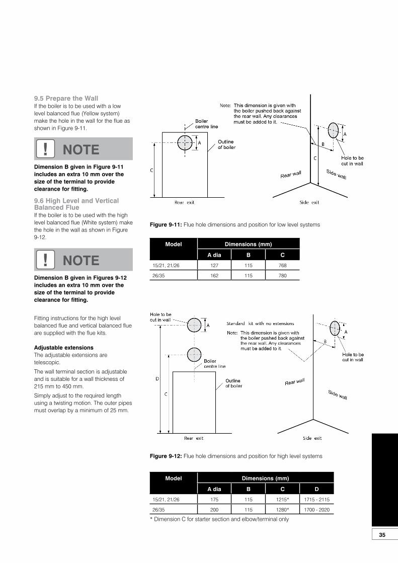
35
9.5 Prepare the WallIf the boiler is to be used with a low level balanced flue (Yellow system) make the hole in the wall for the flue as shown in Figure 9-11.
9.6 High Level and Vertical Balanced FlueIf the boiler is to be used with the highlevel balanced flue (White system) makethe hole in the wall as shown in Figure9-12.
Fitting instructions for the high levelbalanced flue and vertical balanced flueare supplied with the flue kits.
Adjustable extensionsThe adjustable extensions are telescopic.
The wall terminal section is adjustableand is suitable for a wall thickness of 215 mm to 450 mm.
Simply adjust to the required lengthusing a twisting motion. The outer pipesmust overlap by a minimum of 25 mm.
! NOTEDimension B given in Figure 9-11includes an extra 10 mm over the size of the terminal to provide clearance for fitting.
! NOTEDimension B given in Figures 9-12includes an extra 10 mm over the size of the terminal to provide clearance for fitting.
Figure 9-11: Flue hole dimensions and position for low level systems
Model Dimensions (mm)
A dia B C
15/21, 21/26 127 115 768
26/35 162 115 780
Figure 9-12: Flue hole dimensions and position for high level systems
Model Dimensions (mm)
A dia B C D
15/21, 21/26 175 115 1215* 1715 - 2115
26/35 200 115 1280* 1700 - 2020
* Dimension C for starter section and elbow/terminal only
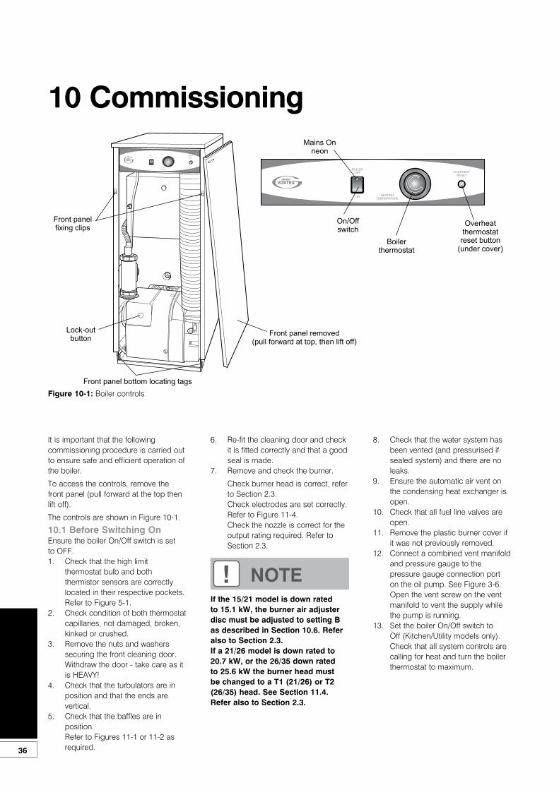
36
10 Commissioning
It is important that the following commissioning procedure is carried out to ensure safe and efficient operation of the boiler.
To access the controls, remove the front panel (pull forward at the top then lift off).
The controls are shown in Figure 10-1.
10.1 Before Switching OnEnsure the boiler On/Off switch is set to OFF.1. Check that the high limit
thermostat bulb and both thermistor sensors are correctly located in their respective pockets. Refer to Figure 5-1.
2. Check condition of both thermostat capillaries, not damaged, broken, kinked or crushed.
3. Remove the nuts and washers securing the front cleaning door. Withdraw the door - take care as it is HEAVY!
4. Check that the turbulators are in position and that the ends are vertical.
5. Check that the baffles are in position.Refer to Figures 11-1 or 11-2 as required.
6. Re-fit the cleaning door and check it is fitted correctly and that a good seal is made.
7. Remove and check the burner.
Check burner head is correct, refer to Section 2.3.Check electrodes are set correctly. Refer to Figure 11-4.Check the nozzle is correct for the output rating required. Refer to Section 2.3.
8. Check that the water system has been vented (and pressurised if sealed system) and there are no leaks.
9. Ensure the automatic air vent on the condensing heat exchanger is open.
10. Check that all fuel line valves are open.
11. Remove the plastic burner cover if it was not previously removed.
12. Connect a combined vent manifold and pressure gauge to the pressure gauge connection port on the oil pump. See Figure 3-6. Open the vent screw on the vent manifold to vent the supply while the pump is running.
13. Set the boiler On/Off switch to Off (Kitchen/Utility models only). Check that all system controls are calling for heat and turn the boiler thermostat to maximum.
Figure 10-1: Boiler controls
! NOTEIf the 15/21 model is down rated to 15.1 kW, the burner air adjuster disc must be adjusted to setting B as described in Section 10.6. Refer also to Section 2.3.If a 21/26 model is down rated to 20.7 kW, or the 26/35 down rated to 25.6 kW the burner head must be changed to a T1 (21/26) or T2 (26/35) head. See Section 11.4. Refer also to Section 2.3.
Boilerthermostat
Overheatthermostat
reset button(under cover)
On/Offswitch
OVERHE ATRESET
HEATINGTEMPERATURE
OVERHEATRESET
BOILEROFF
ON
HEA TINGTE MPE RA TURE
ON
BOILEROFF
Lock-outbutton
Front panel removed(pull forward at top, then lift off)
Front panelfixing clips
Front panel bottom locating tags
GRAN
T
Mains Onneon

37
10.2 Switching On1. Switch on the electricity supply.2. Set the boiler On/Off switch to ON.
A neon in the switch lights when it is in the ON position.The boiler will now light automatically.Note that the neon lights when the boiler is switched on, but does not necessarily indicate the burner is firing.
3. With the boiler On/Off switch to On.The burner fan should start and the burner should light within about 12 seconds. If the burner does not light and the ‘Lock-out’ reset button lights, wait for about 45 seconds then press the reset button to restart the ignition process. This procedure may have to be repeated several times during first lighting.
4. With the burner alight, check the fuel pressure.
5. Refer to the Technical Information, Section 2.3.
6. Adjust the pressure if necessary - see Figure 3-6.
7. Operate the boiler until it reaches normal operating temperature.Check oil supply/return pipe for leaks, rectifying where necessary.
8. Check the operation of the boiler thermostat. Ensure that by turning it anticlockwise it switches the burner off.
9. With the burner alight, re-check the fuel pressure and re-adjust if necessary. Turn the boiler off, remove the pressure gauge and replace the plug in the pump.
10. Ensure that there are no oil leaks, replace the burner cover. Ensure the flexible air tube is connected to both the burner and flue system (balanced flue models).
10.3 Running the Boiler1. Relight the boiler and allow it to run
for at least 20 minutes.2. Check the smoke number, if
satisfactory check the CO2. Set the CO2 to the value given in Section 2.3 for the boiler concerned.
3. Use the hexagonal key supplied to adjust the burner air damper (see Figure 3-6) as required. Turning the screw anti-clockwise closes the damper and increases CO2 level, turning the screw clockwise opens the damper and reduces CO2 level.
4. Re-check the smoke number if the damper has been moved. Under no circumstances must the smoke number be above 1.
5. Check the flue gas temperature by placing the combustion analyser in the low level flue terminal (or into the test point on the starter elbow if either the Green system or Hybrid system is used).
10.4 Balancing the System1. 1. When the boiler has been
adjusted and is running satisfactorily, balance the central heating system by adjusting the radiator lock shield valves. Start with the radiator nearest the boiler and adjust the valves to achieve the required temperature drop across each radiator. If thermostatic radiator valves have been installed, check the system bypass.
2. Switch off the boiler.
10.5 Completion1. With the system hot, check
again for leaks, rectifying where necessary. Drain the system while it is hot to complete the flushing process. Refill and vent (and pressurise if a sealed system) the system.
2. A suitable central heating system inhibitor must be added to protect the system against the effect of corrosion.
3. Consideration should be given to using a suitable antifreeze to prevent damage to the boiler installed in garages, out houses, etc. in areas where electrical power failure can occur in winter months.
4. Replace the top, front and rear panels as necessary.
If the boiler is to be left in service with the User, set the controls and room thermostat (if fitted) to the User’s requirements.
If the boiler is not to be handed over immediately, close the boiler fuel supply valve and switch off the electricity supply.
! NOTEIt is important that the oil pressure is correctly set.
! NOTEIt is important that the air damper is correctly set.
! NOTEAfter commissioning the boiler complete the Commissioning Report in the front of this manual and the OFTEC CD/11 commissioning report.
Leave the top copy with the user and retain the carbon copy.
! CAUTIONIf there is any possibility of the boiler being left during frost conditions, then the boiler and system should be drained. Alternatively, a suitable antifreeze should be used.
! NOTETo allow the boiler to be commissioned and serviced correctly a combustion test point is provided on the front cleaning door.
The CO2 and smoke test may all be carried out using this test point.
The test point is not suitable for measuring boiler efficiency or conventional flue draught.

38
When using the test point on the cleaning cover note that the flue gas temperature reading will be higher than that measured in the flue thus resulting in an inaccurate efficiency reading.
To obtain an accurate flue gas temperature and efficiency, the reading can only be measured outside through the low level flue terminal. For high level and vertical balanced flues the reading may be taken from the flue kit test point provided . Refer to Section 2.3.
For Conventional flues, flue draught, combustion and efficiency measurement, a test point is provided in the conventional flue connector section. See Figure 9-5.
10.6 Air Adjuster Disc - 15/21 onlyTo adjust the 15/21 air adjuster disc when downrating - See Figure 10-2
1. 1. Ensure the boiler is isolated from the electrical supply.
2. Remove the burner from the boiler.3. Undo the two screws and remove
the air inlet cover from the side of the burner.
4. The secondary air shutter disc is factory set in position ‘C’ – i.e. with the cut-out marked C located against the die-cast boss on the fan housing - suitable for outputs of 18.1 and 20.7 kW only. See Figure 10-2.
5. Remove the screw from the centre of the air shutter disc, and re-position the disc such that the cut-out ‘B’ (corresponding to 15.1 kW output setting – See Section 2.3) is located against the cast boss on the fan housing. Replace the screw in the centre of the air shutter disc and tighten.
6. Re-fit the air inlet cover to the side of the burner and reassemble in reverse order.
Figure 10-2: 15/21 air adjuster disc at position ‘C’
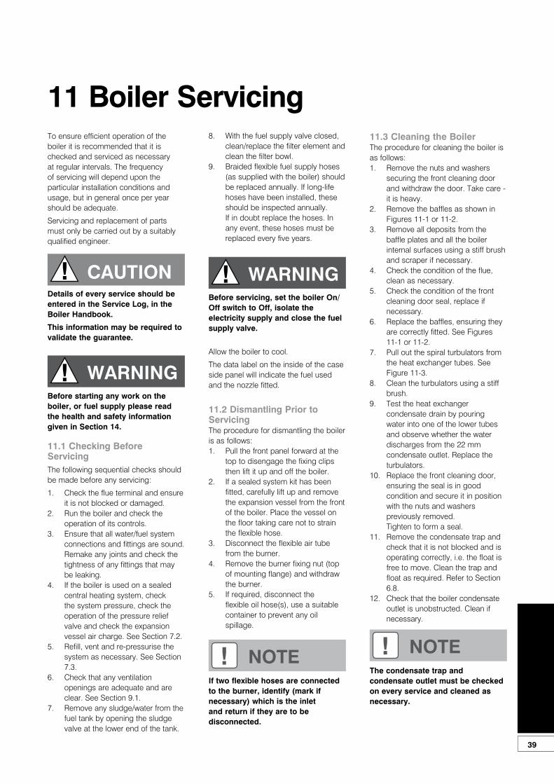
39
To ensure efficient operation of the boiler it is recommended that it is checked and serviced as necessary at regular intervals. The frequency of servicing will depend upon the particular installation conditions and usage, but in general once per year should be adequate.
Servicing and replacement of parts must only be carried out by a suitably qualified engineer.
11.1 Checking Before ServicingThe following sequential checks should be made before any servicing:
1. Check the flue terminal and ensure it is not blocked or damaged.
2. Run the boiler and check the operation of its controls.
3. Ensure that all water/fuel system connections and fittings are sound.Remake any joints and check the tightness of any fittings that may be leaking.
4. If the boiler is used on a sealed central heating system, check the system pressure, check the operation of the pressure relief valve and check the expansion vessel air charge. See Section 7.2.
5. Refill, vent and re-pressurise the system as necessary. See Section 7.3.
6. Check that any ventilation openings are adequate and are clear. See Section 9.1.
7. Remove any sludge/water from the fuel tank by opening the sludge valve at the lower end of the tank.
8. With the fuel supply valve closed, clean/replace the filter element and clean the filter bowl.
9. Braided flexible fuel supply hoses (as supplied with the boiler) should be replaced annually. If long-life hoses have been installed, these should be inspected annually. If in doubt replace the hoses. In any event, these hoses must be replaced every five years.
Allow the boiler to cool.
The data label on the inside of the case side panel will indicate the fuel used and the nozzle fitted.
11.2 Dismantling Prior to ServicingThe procedure for dismantling the boileris as follows:1. Pull the front panel forward at the
top to disengage the fixing clips then lift it up and off the boiler.
2. If a sealed system kit has been fitted, carefully lift up and remove the expansion vessel from the front of the boiler. Place the vessel on the floor taking care not to strain the flexible hose.
3. Disconnect the flexible air tube from the burner.
4. Remove the burner fixing nut (top of mounting flange) and withdraw the burner.
5. If required, disconnect the flexible oil hose(s), use a suitable container to prevent any oil spillage.
11.3 Cleaning the BoilerThe procedure for cleaning the boiler isas follows:1. Remove the nuts and washers
securing the front cleaning door and withdraw the door. Take care - it is heavy.
2. Remove the baffles as shown in Figures 11-1 or 11-2.
3. Remove all deposits from the baffle plates and all the boiler internal surfaces using a stiff brush and scraper if necessary.
4. Check the condition of the flue, clean as necessary.
5. Check the condition of the front cleaning door seal, replace if necessary.
6. Replace the baffles, ensuring they are correctly fitted. See Figures 11-1 or 11-2.
7. Pull out the spiral turbulators from the heat exchanger tubes. See Figure 11-3.
8. Clean the turbulators using a stiff brush.
9. Test the heat exchanger condensate drain by pouring water into one of the lower tubes and observe whether the water discharges from the 22 mm condensate outlet. Replace the turbulators.
10. Replace the front cleaning door, ensuring the seal is in good condition and secure it in position with the nuts and washers previously removed.Tighten to form a seal.
11. Remove the condensate trap and check that it is not blocked and is operating correctly, i.e. the float is free to move. Clean the trap and float as required. Refer to Section 6.8.
12. Check that the boiler condensate outlet is unobstructed. Clean if necessary.
11 Boiler Servicing
! CAUTIONDetails of every service should be entered in the Service Log, in the Boiler Handbook.
This information may be required to validate the guarantee.
! WARNINGBefore starting any work on theboiler, or fuel supply please read the health and safety information given in Section 14.
! WARNINGBefore servicing, set the boiler On/Off switch to Off, isolate the electricity supply and close the fuel supply valve.
! NOTEIf two flexible hoses are connected to the burner, identify (mark if necessary) which is the inlet and return if they are to be disconnected.
! NOTEThe condensate trap and condensate outlet must be checked on every service and cleaned as necessary.
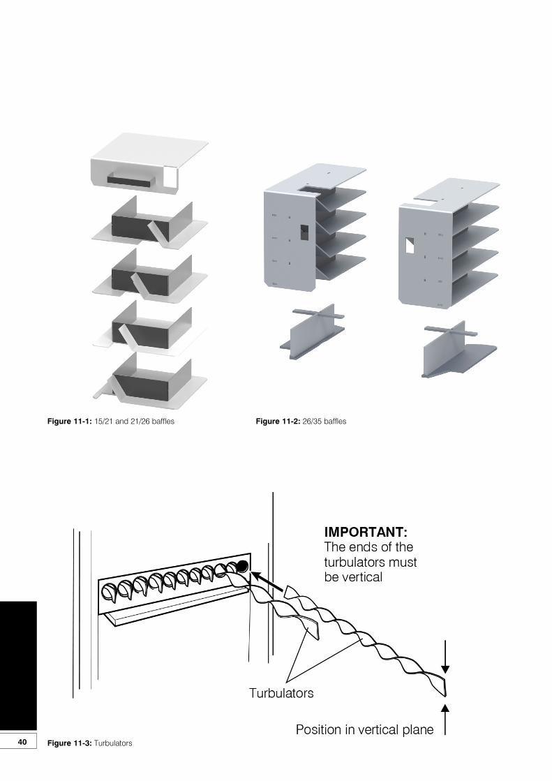
40
Figure 11-1: 15/21 and 21/26 baffles Figure 11-2: 26/35 baffles
Figure 11-3: Turbulators
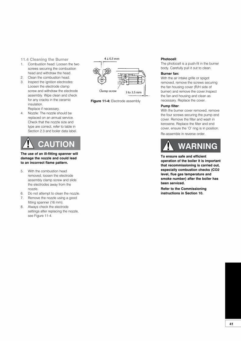
41
11.4 Cleaning the Burner1. Combustion head: Loosen the two
screws securing the combustion head and withdraw the head.
2. Clean the combustion head.3. Inspect the ignition electrodes:
Loosen the electrode clampscrew and withdraw the electrodeassembly. Wipe clean and check for any cracks in the ceramic insulation.Replace if necessary.
4. Nozzle: The nozzle should be replaced on an annual service.Check that the nozzle size and type are correct, refer to table in Section 2.3 and boiler data label.
5. With the combustion head removed, loosen the electrode assembly clamp screw and slide the electrodes away from the nozzle.
6. Do not attempt to clean the nozzle.7. Remove the nozzle using a good
fitting spanner (16 mm).8. Always check the electrode
settings after replacing the nozzle, see Figure 11-4.
Photocell:The photocell is a push-fit in the burner body. Carefully pull it out to clean.
Burner fan:With the air intake grille or spigot removed, remove the screws securing the fan housing cover (R/H side of burner) and remove the cover.Inspect the fan and housing and clean as necessary. Replace the cover.
Pump filter:With the burner cover removed, remove the four screws securing the pump end cover. Remove the filter and wash in kerosene. Replace the filter and end cover, ensure the ‘O’ ring is in position.
Re-assemble in reverse order.
! CAUTIONThe use of an ill-fitting spanner will damage the nozzle and could lead to an incorrect flame pattern.
Figure 11-4: Electrode assembly
! WARNINGTo ensure safe and efficient operation of the boiler it is important that recommissioning is carried out, especially combustion checks (CO2 level, flue gas temperature and smoke number) after the boiler has been serviced.
Refer to the Commissioning instructions in Section 10.

42
12 Fault Finding12.1 Boiler Fault FindingAlways isolate the electricity supply to the boiler before working on the boiler.
FaultRemedies
Boiler will not start:
No fuel supply Ensure that an adequate supply of fuel is available and that the fuel supply valve is open.Check the condition of the fuel filter, clean if necessary.Ensure fuel supply is reaching burner and vent pump.
No electricity supply Ensure electricity supply to the boiler is switched on and that all controls are calling for heat.Ensure that the overheat thermostat has not tripped, reset if necessary.Check that a mains supply is present at the burner terminal block.If not, check the boiler and overheat thermostat.
Burner not starting - fuel and electricity sup-plies present
Press the reset button on the burner control box if it is lit.Refer to burner fault finding charts.
Burner lights but goes to lock-out If the flame is unstable, check the combustion settings.Refer to burner fault finding charts.
Boiler works but:
Visible smoke from flue or high smoke number
Insufficient air supply - check the air damper setting and the condition of the fan.Check room ventilation is adequate, see Section 9.1.Check the nozzle size and type.Fuel pressure may be too high - check and adjust.
Burner pulses Insufficient air supply - check the air damper setting and the condition of the fan.Check room ventilation is adequate, see Section 9.1.Check the nozzle size and type.
Flame slow to stabilise during start up Insufficient air supply - check the air damper setting and the condition of the fan.Check room ventilation is adequate, see Section 9.1.Check the nozzle size and type.Fuel pressure may be too low - check and adjust.Insufficient draught - clean boiler heat exchanger and check condition of flue.
Water temperature low Undersize nozzle and/or low fuel pressure.Check condition of boiler heat exchanger and clean if necessary.Check the boiler thermostat.Check the combustion settings.Check the condition of the fuel filter.
Boiler operating on overheat thermostat Faulty boiler thermostat. No circulation, check circulating pump. Check for air lock.
Fumes and puffing during starting (conven-tional flue)
Check the condition of the chimney, ensure it is not blocked and is high enough to produce therequired draught. Check that there is an adequate air supply near the burner and that a kitchenfan is not drawing products out of the burner.
Oil odours Check all fuel line connections, remake as necessary.
Combustion fumes smell Check boiler cleaning cover and seal are correctly fitted.Check burner is correctly fitted onto flange.Check flue is correctly sealed into flue outlet of boiler.Check the condensate pipe and trap are operating correctly
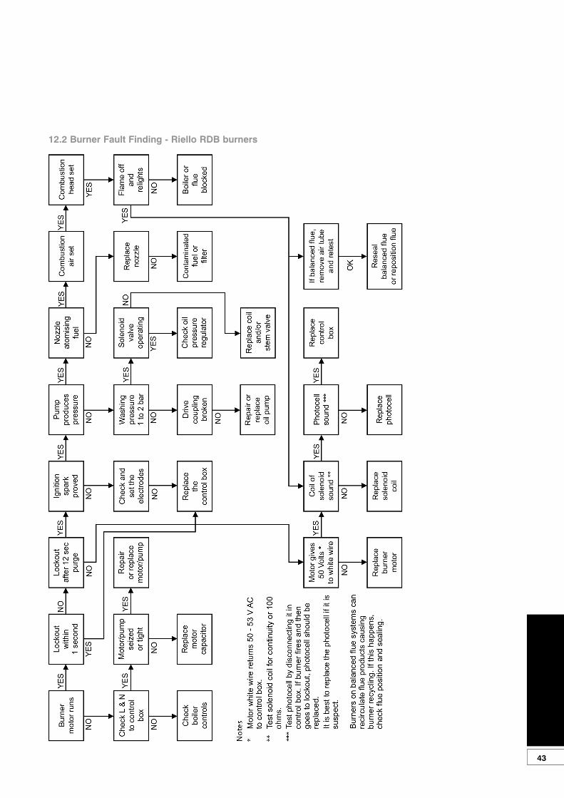
43
12.2 Burner Fault Finding - Riello RDB burners

44
12.3 Circulating Pump Fault DiagnosisThe indicator LED, located around the circumference of the red control knob, can assit in diagnosing and rectifying a fault with the pump. See the table below.
LED condition Meaning Diagnostic Cause Remedy
Green Pump operating Pump runs according to the red knob setting
Normal operation N/A
Flashes red and green
Pump is operating but stoipped
Pump restarts itself after fault has disappeared
UndervoltageVoltage <160V
OROvervoltage
Voltage >253V
Check supply voltage is 195V<V<253V
Overheating:temperature inside motor
too high
Check water and ambient temperature
Flashes red Pump not operating Pump stopped (blocked) Pump does not restart itself due to a permanent failure
Replace pump
LED off No power supply No voltage to pump control electronics
Pump is not connected to power supply
Check cable connection
LED is damaged Check if pump is running
Electronics are damaged Replace pump

45
13 Spare Parts13.1 Boiler parts list
Description Part number
Cleaning door nut and washer set EFBS14
Double pole switch EFBS19
Baffle set (complete) - 15/21 and 21/26 VBS96
Baffle set (complete) - 26/35 VBS97
Turbulator baffle - single (all models) VBS98
Sealed system - Expansion vessel 12 litre MPSS01
Sealed system - Water pressure gauge MPSS02
Sealed system pressure relief valve MPCBS50X
Sealed system - Expansion vessel flexible hose MPSS04
Cleaning door rope seal - 15/21 and 21/26 VBS20L
Cleaning door rope seal - 26/35 VBS15
Overheat thermostat TPBS33
Boiler thermostat MPCBS29
Circulating pump - 6 m head (non HE) MPCBS23
Circulating pump - 7 m head (non HE) VBS54
Circulating pump - 7 m head (HE) VBS126
White pump cable with plug (for HE pump) VBS126A
Black pump cable with plug (for HE pump) VBS126B
Return connection assembly (22 mm) with auto air vent VBS61
Snorkel tube FKS35
Cleaning door - 15/21 and 21/26 VBS92
Cleaning door - 26/35 VBS69
Pump valves (set of 2) - 22 mm MPCBS77
Condensate trap VBS02
Condensate flexible hose VBS102
13.2 Burner heads
Figure 13-1: Burner heads

46
This section gives exploded views of the Riello burners in the Grant VORTEX Eco boilers amd parts lists associated with them.
13.3 Riello RDB2.2 burners
Figure 13-3: Riello RDB1, RDB2 and RDB2.2 burner components diagram
28
3
4
56
13
13
25
24
21
20
1819
1415
16
10
9
31
11
12
17
23
2230
26
727
28
29
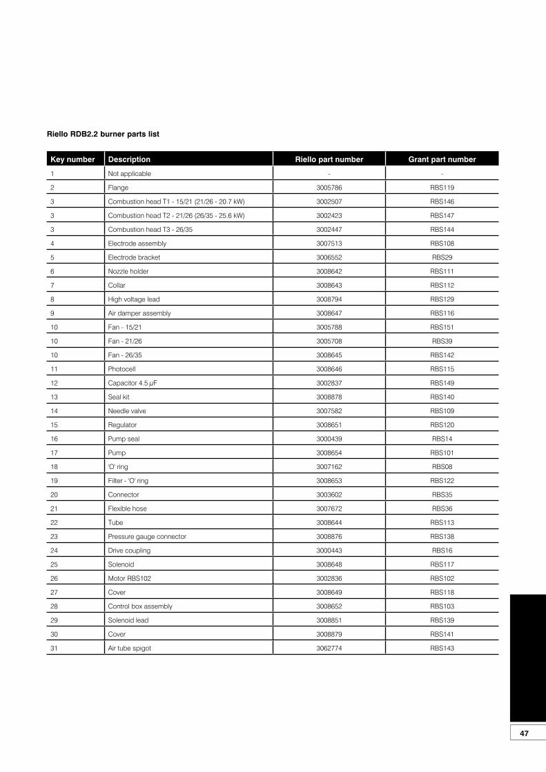
47
Riello RDB2.2 burner parts list
Key number Description Riello part number Grant part number
1 Not applicable - -
2 Flange 3005786 RBS119
3 Combustion head T1 - 15/21 (21/26 - 20.7 kW) 3002507 RBS146
3 Combustion head T2 - 21/26 (26/35 - 25.6 kW) 3002423 RBS147
3 Combustion head T3 - 26/35 3002447 RBS144
4 Electrode assembly 3007513 RBS108
5 Electrode bracket 3006552 RBS29
6 Nozzle holder 3008642 RBS111
7 Collar 3008643 RBS112
8 High voltage lead 3008794 RBS129
9 Air damper assembly 3008647 RBS116
10 Fan - 15/21 3005788 RBS151
10 Fan - 21/26 3005708 RBS39
10 Fan - 26/35 3008645 RBS142
11 Photocell 3008646 RBS115
12 Capacitor 4.5 µF 3002837 RBS149
13 Seal kit 3008878 RBS140
14 Needle valve 3007582 RBS109
15 Regulator 3008651 RBS120
16 Pump seal 3000439 RBS14
17 Pump 3008654 RBS101
18 'O' ring 3007162 RBS08
19 Filter - 'O' ring 3008653 RBS122
20 Connector 3003602 RBS35
21 Flexible hose 3007672 RBS36
22 Tube 3008644 RBS113
23 Pressure gauge connector 3008876 RBS138
24 Drive coupling 3000443 RBS16
25 Solenoid 3008648 RBS117
26 Motor RBS102 3002836 RBS102
27 Cover 3008649 RBS118
28 Control box assembly 3008652 RBS103
29 Solenoid lead 3008851 RBS139
30 Cover 3008879 RBS141
31 Air tube spigot 3062774 RBS143
48
Under the Consumer Protection Act 1987 and Section 6 of the Health and Safety at Work Act 1974, we are required to provide information on substances hazardous to health (COSHH Regulations 1988).
Adhesives, sealants and paints used in the manufacture of the product are cured and present no known hazards when used in the manner for which they are intended.
The following other materials are present in the product:
14.1 Insulation MaterialsMaterial Types: Ceramic fibre board, mineral wool.
Description: Rigid board, slabs, sleeves, gaskets, ropes.
Known Hazards: May cause temporary irritation or rash to skin. High dust levels may irritate eyes and upper respiratory system.
Precautions: Avoid unnecessary or rough handling, or harsh abrasion of boards. Normal handling and use of material should not produce high dust levels.
Avoid inhalation, and contact with skin and eyes.
After handling always follow normal good hygiene practices.
Protection: Use disposable gloves, face mask and eye protection.
First Aid: Eyes - If irritation occurs, wash eyes with copious amounts of water.
If symptoms persist, seek immediate medical advice.
Skin - If irritation occurs, wash under running water before washing with soap and water.
Inhalation - Remove to fresh air, drink water to clear throat and blow nose to remove dust/fibres.
Ingestion - Drink plenty of water.
14.2 Sealant MaterialsMaterial Types: Silicone elastomer.
Description: Sealant and adhesive.
Known Hazards: Irritation to eyes.
Precautions: Avoid inhalation of vapour, contact with eyes and prolonged or repeated contact with skin.
After handling always follow normal good hygiene practices.
Protection: Use eye protection. Rubber or plastic gloves should be worn where repeated contact occurs and a face mask worn when working in confined spaces.
First Aid: Eyes - Flush eyes with water for 15 minutes. Seek immediate medical attention.
Skin - Wipe off and wash with soap and water.
Inhalation - Remove to fresh air.
14.3 Kerosene and Gas Oil Fuels (mineral oils)Known Hazards: The effect of mineral oils on the skin vary according to the duration of exposure and the type of oil.
The lighter fractions remove the protective grease naturally present on the skin, leaving it dry, liable to crack and more prone to damage by cuts, abrasions and irritant chemicals.
Skin rashes (Oil acne) most often on arms, but also on any part of the body in contact with oil or oily clothing.
Contact with fuel oils can cause dermatitis.
Precautions: Avoid as far as possible any skin contact with mineral oil or with clothing contaminated with mineral oil.
The use of a lanolin-based barrier cream is recommended, in conjunction with regular washing with soap and rinsing with water to ensure all oil is removed from the skin.
Take care to prevent clothing, especially underwear, from becoming contaminated with oil.
Do not put oily rags or tools in pockets, especially trouser pockets.
Have first-aid treatment at once for an injury, however slight.
Do not inhale any vapours from mineral oils.
14 Health and Safety Information
49
15 Recycling and DisposalCirculating PumpThe circulating pump must not be disposed of in normal doimestic waste as most of the materials used in it’s construction can be recycled.
For details on how to responsibly dispose of this pump, please visit:www.wilo.com/recycling
In EU CountriesThe following information is provided to enable regulatory compliance with the European Union (EU) directives identified and any amendments made to these directives when using electrical or electronic equipment in EU countries.
Disposal of Electrical and Electronic EquipmentEuropean Union (EU) Directive 2002/96/EC Waste Electrical and Electronic Equipment (WEEE)
Do not dispose of electrical or electronic equipment in landfill sites. In the EU, it is the individual recipient’s responsibility to ensure that discarded electrical or electronic materials are collected and recycled according to the requirements of EU environmental law.
Disposal of Surplus PackagingEuropean Parliament and Council Directive 94/62/EC Packaging and Packaging Waste
Do not dispose of surplus packaging in landfill sites. In the EU, it is the individual recipient’s responsibility to ensure that packaging materials are collected and recycled according to the requirements of EU environmental law.
In non-EU CountriesIn non-EU countries, dispose of electrical and electronic equipment and all surplus packaging in accordance with national and regional regulations.
Complies with EC Low voltage Electromagnetic compatibility and Boiler efficiency Directives.

50
16 Guarantee16.1 The Vortex Oil BoilerGuaranteeYou are now the proud owner of a Grant Vortex condensing boiler from Grant Engineering (UK) Limited which has been designed to give years of reliable, trouble free, operation.
Grant Engineering (UK) Limited guarantees the manufacture of the boiler including all electrical and mechanical components for a period of twelve months from the date of installation4, provided that the boiler has been installed in full accordance with the installation and servicing instructions issued.
This will be extended to a total period of two years if the boiler is registered with Grant Engineering (UK) Limited within thirty days of installation4 and serviced at twelve monthly intervals3. See main Terms and Conditions below.
Registering the product with Grant Engineering (UK) LimitedPlease register your Grant Vortex condensing boiler with Grant Engineering UK Limited within thirty days of installation. To do so visit www.grantuk.com and follow the links to the ‘Homeowners Zone’, where you can register your boiler for a further twelve months guarantee (giving two years from the date of installation4). This does not affect your statutory rights1.
If a fault or defect occurs within the manufacturer’s guarantee periodIf your boiler should fail within the guarantee period, you must contact Grant Engineering (UK) Limited who will arrange for the repair under the terms of the guarantee, providing that the boiler has been correctly installed, commissioned and serviced (if the appliance has been installed for more than twelve months) by a competent person and the fault is not due to tampering, running out of oil, oil contamination, debris, system water contamination, misuse, trapped air or the failure of any external components not supplied by Grant Engineering (UK) Limited, e.g. fire valve, motorised valve, etc.
This two year guarantee only applies if the boiler is registered with Grant Engineering (UK) Limited within thirty days of installation4 and is serviced after twelve months3.
manufacturer’s guarantee’.
Extent of manufacturer’s guarantee:The manufacturer’s guarantee does not cover the following:• If the boiler has been installed for
over two years.• If the boiler has not been installed,
commissioned, or serviced by a competent person in accordance with the installation and servicing instructions.
• The serial number has been removed or made illegible.
• Fault(s) due to accidental damage, tampering, unauthorised adjustment, neglect, misuse or operating the boiler contrary to the manufacturer’s installation and servicing instructions.
• Damage due to external causes such as bad weather conditions (flood, storms, lightning, frost, snow, or ice), fire, explosion, accident or theft.
• Fault(s) due to incorrectly sized expansion vessel(s), incorrect vessel charge pressure or inadequate expansion on the system.
• Fault(s) caused by external electrics and external components not supplied by Grant Engineering (UK) Limited.
• Problems caused by lack of oil or faults with the oil storage and supply system.
• Fault(s) due to contamination of the oil storage and supply system, e.g. water or debris.
• Bleeding or removing oil storage tank contamination or blockages from oil lines.
• Problems due to the flue system being incorrectly fitted or not installed to meet installation requirements.
• Boiler servicing, de-scaling or flushing.
• Cleaning out condensate traps/discharge pipes or thawing out frozen condensate pipework.
• Checking and replenishing system pressure.
• Oil supply pipelines, electrical cables and plugs, external controls not supplied by Grant Engineering (UK) Limited.
• Heating system components, such as radiators, pipes, fittings, pumps and valves not supplied by Grant Engineering (UK) Limited.
• Instances where the oil boiler has been un-installed and re-installed in another location.
• Use of spare parts not authorised
In the first instanceContact your installer or commissioning engineer to ensure that the fault does not lie with the system components or any incorrect setting of the system controls that falls outside of the manufacturer’s guarantee otherwise a service charge could result. Grant Engineering (UK) Limited will not be liable for any charges arising from this process.
If a fault covered by the manufacturer’s guarantee is foundAsk your installer to contact Grant Engineering (UK) Limited Service Department on +44 (0)1380 736920 who will arrange for a competent service engineer to rectify the fault.
Remember - before you contact Grant Engineering (UK) Limited:• Ensure the boiler has been
installed, commissioned and serviced by a competent person in accordance with the installation and servicing instructions.
• Ensure there is oil to supply the burner.
• Ensure the problem is not being caused by the heating system or its controls. Consult the boiler handbook for guidance.
Free of charge repairsDuring the two year guarantee period no charge for parts or labour will be made, provided that the boiler has been installed and commissioned correctly in accordance with the manufacturer’s installation and servicing instructions, it was registered with Grant Engineering (UK) Limited within thirty days of installation4 and, for boilers over twelve months old, details of annual service is available3.
The following documents must be made available to Grant Engineering (UK) Limited on request:• Proof of purchase• CD10 Installation Completion Form
(or equivalent document)• CD11 Commissioning Report Form
(or equivalent document)• Service documents (CD11 or
equivalent document)
Chargeable repairsA charge may be made (if necessary following testing of parts) if the breakdown is due to any fault(s) caused by the plumbing or heating system, e.g. contamination of parts due to system contamination, sludge, scale, debris or trapped air. See ‘Extent of

51
by Grant Engineering (UK) Limited.• Consumable items including,
but not limited to, oil nozzles, oil hoses, gaskets.
IMPORTANTThe nozzle and braided oil hose supplied with the boiler are only covered for the period up to the time of the first service (twelve months). Both must be changed on the first service and on every annual service thereafter.
IMPORTANTDo not wait until the fuel supply runs out before you re-order. Sludge in the bottom of the tank may be drawn into the fuel lines. It is recommended that the boiler is switched off when the new oil supply is delivered and that the fuel is allowed to settle for an hour before restarting the boiler.
Terms of manufacturer’s guarantee:• The Company shall mean Grant
Engineering (UK) Limited.• The boiler must be installed by
a competent installer and in full accordance with the relevant Codes of Practice, Regulations and Legislation in force at the time of installation.
• The boiler is guaranteed for two years from the date of installation4, providing that after twelve months the annual service has been completed3 and the boiler registered with the Company within thirty days of installation. Any work undertaken must be authorised by the Company and carried out by a competent service engineer.
• The shell (heat exchanger) of the oil boiler is also covered by a five year parts only guarantee from the date of installation4. This is subject to the following:• The boiler is operated
correctly, in accordance with the installation and servicing instructions.
• Proof is provided that the system has been flushed or chemically cleaned where appropriate (refer to BS 7593) and that the required quantity of a suitable corrosion inhibitor added.
• Proof of annual servicing (including the checking of any expansion vessels and pressure relief valves) must be provided if and when requested by the Company.IMPORTANT
Grant Engineering (UK) Limited strongly recommends that a Grant Mag-One in-line magnetic filter/s (or equivalent5) is fitted in the heating system pipework. This should be installed and regularly serviced in accordance with the filter manufacturer’s instructions.
• This guarantee does not cover breakdowns caused by incorrect installation, neglect, misuse, accident or failure to operate the boiler in accordance with the manufacturer’s installation and servicing instructions.
• The boiler is registered with the Company within thirty days of installation. Failure to do so does not affect your statutory rights1.
• The balance of the guarantee is transferable providing the installation is serviced prior to the dwelling’s new owners taking up residence. Grant Engineering (UK) Limited must be informed of the new owner’s details.
• The Company will endeavour to provide prompt service in the unlikely event of a problem occurring, but cannot be held responsible for any consequences of delay however caused.
• This guarantee applies to Grant Engineering (UK) Limited boilers purchased and installed on the UK mainland, Isle of Wight, Channel Islands and Scottish Isles only2. Provision of in-guarantee cover elsewhere in the UK is subject to agreement with the Company.
• All claims under this guarantee must be made to the Company prior to any work being undertaken. Invoices for call out/repair work by any third party will not be accepted unless previously authorised by the Company.
• Proof of purchase and date of installation, commissioning and service documents must be provided on request.
• If a replacement boiler is supplied under the guarantee (due to a manufacturing fault) the product guarantee continues from the installation date of the original boiler, and not from the installation date of the replacement4.
• The oil boiler must be connected to a mains water supply (installations utilising a private water supply are not covered by this guarantee).
• Breakdown/failure due to lime
scale will not be covered by this guarantee.
• The replacement of a boiler under this guarantee does not include any consequential costs, such as the removal or replacement of worktops, kitchen units, etc.
• The boiler (excluding external modules) must not be sited in a location where it may be subjected to frost.
Hard water advice(for Combi boilers only)If you live in a hard water area, protection against scaling must be given to the domestic hot water heat exchanger of your combination boiler.
You should fit an appropriate scale inhibitor or water softener as any breakdown caused by water scaling is not covered by the manufacturer’s guarantee. Ask your installer for advice.
Foot notes:1. Your statutory rights entitle
you to a one year guarantee period only.
2. The UK mainland consists of England, Scotland and Wales only. Please note that for the purposes of this definition, Northern Ireland, Isle of Man and Scilly Isles are not considered part of the UK mainland.
3. Your boiler must be regularly serviced as per the installation and servicing instructions, (even when the guarantee has expired) to prolong the lifespan and ensure it is operating safely and efficiently.
4. The guarantee period will commence from the date of installation, unless the installation date is more than six months from the date of purchase, in which case the guarantee period will commence six months from the date of purchase.
5. As measured by gauss. The Mag-One magnetic filter has a gauss measurement of 12000.
Version 1.0

52
17 Notes

53

54

55

GRANT ENGINEERING (UK) LTDHopton House, Hopton Industrial Estate, Devizes, Wiltshire. SN10 2EU
Telephone: +44 (0)1380 736920 Fax: +44 (0)1380 736991Email: [email protected] Website: www.grantuk.com