Embed Size (px)
Citation preview
SPECIFICATION AND DESCRIPTION
GRAND CARAVAN EX
February 2016 Revision D
Units 208B-5265 to TBD
GRAND CARAVAN EX
SPECIFICATION
AND DESCRIPTION
UNITS 208B-5265 TO TBD
FEBRUARY 2016
REVISION D
Cessna Aircraf t Company
P.O. Box 7706
Wichi ta , Kansas 67277-7706
February 2016, Revision D1
GRAND CARAVAN EX
INTRODUCTION
This “Specifi cation and Description” is published for the
purpose of providing general information for the evaluation
of the design, performance and equipment of the Cessna
Grand Caravan EX aircraft. Should more detailed data be
required, it can be obtained by contacting:
Cessna Aircraft Company
P.O. Box 7704
Wichita, Kansas 67277
Telephone: 316-517-6081
Fax: 316-517-7850
This document describes only the Cessna Model 208B
Grand Caravan EX aircraft, Unit Serial Number 5265 and
on, and its powerplant and equipment.
Also included is the Cessna warranty applicable to the
Cessna Model 208B Grand Caravan EX aircraft and the
Caravan Crew Training Agreement. In the event of any con-
fl ict or discrepancy between this document and the basic
purchase agreement to which it may be appended, terms
specifi ed in the basic purchase agreement govern.
Due to the time span between the date of this Specifi cation
and Description and the scheduled delivery date of the air-
craft, Cessna reserves the right to revise the “Specifi cation
and Description” whenever occasioned.
WARNING: This product contains Halon 1211, Halon 1301, and also R-134A. Furthermore, the product was manufactured
with CFC-12 and 1-1-1 Trichloroethane, substances which harm public health and environment by destroying ozone in the
upper atmosphere.
February 2016, Revision D2
GRAND CARAVAN EX
CESSNA GRAND CARAVAN EX SPECIFICATION AND DESCRIPTION
SECTION PAGE
1. General Description ............................................................................................................................................................
2. Performance .........................................................................................................................................................................
3. Structural Design Criteria ................................................................................................................. .................................
4. Fuselage Group ................................................................................................................................ ...................................
5. Wing Group ..........................................................................................................................................................................
6. Empennage Group .............................................................................................................................................................
7. Landing Gear .................................................................................................................................... ....................................
8. Propulsion
8.1 Powerplant ......................................................................................................................................................................
8.2 Propeller ..........................................................................................................................................................................
9. Systems
9.1 Flight Controls ...........................................................................................................................................................
9.2 Fuel System ................................................................................................................................................................
9.3 Electrical System ................................................................................................................. ......................................
9.4 Lighting System ................................................................................................................... ......................................
9.5 Environmental System.......................................................................................................... ....................................
9.6 Pitot-Static System .............................................................................................................. ......................................
9.7 Vacuum System .........................................................................................................................................................
9.8 Garmin G1000 Avionics System ...........................................................................................................................
10. Floatplane . ............................................................................................................................................................................
11. Standard Equipment
11.1 Avionics ............................................................................................................................... ........................................
11.2 Engine Instruments ..................................................................................................................................................
11.3 Flight Instruments .....................................................................................................................................................
11.4 Flight Controls ..................................................................................................................... ......................................
11.5 Environmental ............................................................................................................................................................
11.6 Electrical Power ........................................................................................................................................................
11.7 Exterior Lights .............................................................................................................................................................
11.8 Interior Lights .............................................................................................................................................................
11.9 Powerplant ..................................................................................................................................................................
11.10 Fuel System ................................................................................................................................................................
11.11 Interior ..........................................................................................................................................................................
11.12 Exterior .........................................................................................................................................................................
12. Documentation and Technical Publications ..................................................................................................................
13. Maintenance Programs .....................................................................................................................................................
14. Limited Warranties
14.1 Cessna Grand Caravan EX Limited Warranty ....................................................................................................
14.2 Pratt & Whitney Canada Inc. ..................................................................................................................................
14.3 Honeywell/Bendix/King Warranty .........................................................................................................................
14.4 Hartzell Limited Warranty .......................................................................................................................................
15. Grand Caravan EX Crew Training Agreement ..............................................................................................................
FIGURE I — GRAND CARAVAN EX EXTERIOR DIMENSIONS ..................................................................................................
FIGURE II — GRAND CARAVAN EX INTERIOR DIMENSIONS ................................................................................................
FIGURE III — GRAND CARAVAN EX INSTRUMENT PANEL AND PEDESTAL LAYOUT ...................................................
TABLE OF CONTENTS
3
7
8
8
9
9
10
10
11
11
12
12
12
13
13
13
13
14
17
17
17
17
18
18
18
18
18
18
19
19
20
21
22
23
23
25
27
4
5
16
February 2016, Revision D3
GRAND CARAVAN EX
1. GENERAL DESCRIPTION
The Cessna Grand Caravan EX is an unpressurized sin-
gle-engine high wing turboprop aircraft with fi xed land-
ing gear. The aircraft can accommodate up to 14 persons
including a minimum crew of one. (Operations with more
than nine passengers must be approved by the register-
ing country’s aviation authority.) Suitable allowance for
luggage and optional equipment is also provided.
The powerplant is a Pratt and Whitney of Canada PT6A-
140 turboprop engine mounted in the nose of the aircraft
fuselage.
1.1 CERTIFICATION
Certifi cation basis is to U.S. FAA FAR Part 23 Require-
ments—day, night, VFR, IFR and fl ight-into-icing condi-
tions when equipped with the appropriate options. Export
certifi cation requirements may require additional equip-
ment and charges.
1. GENERAL DESCRIPTION
POWERPLANT .............................................................................. Pratt & Whitney PT6A-140 867 shp @ 1900 rpm
PROPELLER...................... Hartzell, Constant Speed, Full Feathering, Reversible Pitch, 3 Blades, 106 in. Diameter
LOADING
Wing .......................................................................................................................................................................................
Power .....................................................................................................................................................................................
31.49 lb/ft2
10.15 lb/shp
February 2016, Revision D4
GRAND CARAVAN EX
52 ft 1in
41 ft 7 in
15 ft 1 inMAX
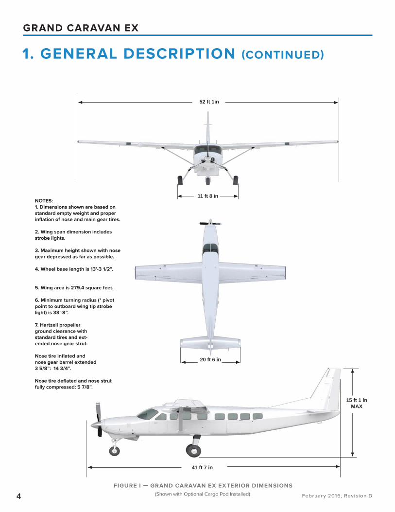
FIGURE I — GRAND CARAVAN EX EXTERIOR DIMENSIONS
1. GENERAL DESCRIPTION (CONTINUED)
11 ft 8 in
20 ft 6 in
(Shown with Optional Cargo Pod Installed)
NOTES:
1. Dimensions shown are based on
standard empty weight and proper
infl ation of nose and main gear tires.
2. Wing span dimension includes
strobe lights.
3. Maximum height shown with nose
gear depressed as far as possible.
4. Wheel base length is 13’-3 1/2”.
5. Wing area is 279.4 square feet.
6. Minimum turning radius (* pivot
point to outboard wing tip strobe
light) is 33’-8”.
7. Hartzell propeller
ground clearance with
standard tires and ext-
ended nose gear strut:
Nose tire infl ated and
nose gear barrel extended
3 5/8”: 14 3/4”.
Nose tire defl ated and nose strut
fully compressed: 5 7/8”.
February 2016, Revision D5
GRAND CARAVAN EX
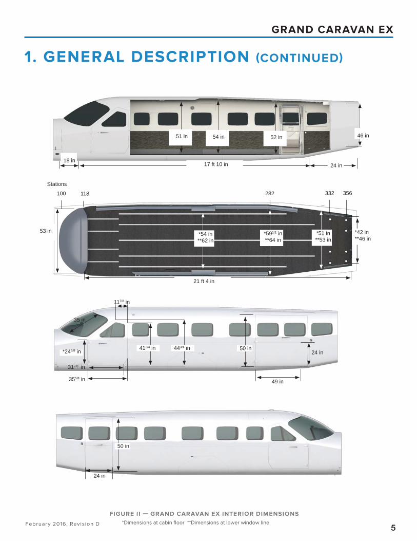
FIGURE II — GRAND CARAVAN EX INTERIOR DIMENSIONS
1. GENERAL DESCRIPTION (CONTINUED)
35 in
*243/8 in
117/8 in
50 in24 in
413/4 in 443/4 in
317/8 in
355/8 in
24 in
50 in
17 ft 10 in
54 in51 in 52 in 46 in
24 in
*54 in**62 in
*591/2 in**64 in
*51 in**53 in
21 ft 4 in
*42 in**46 in
Stations
100 118 282 332 356
53 in
*Dimensions at cabin fl oor **Dimensions at lower window line
49 in
18 in
February 2016, Revision D6
GRAND CARAVAN EX
1. GENERAL DESCRIPTION (CONTINUED)
15 ft 1 in
41 ft 7 in
52 ft 1 in
279.40 ft2
0 degrees
+3 degrees
0.586
9.555
66.474 in
20 ft 6 in
70.04 ft2
0° at elevator hinge line
6.0
41.984 in
8 ft 2 in
39.92 ft2
+9.437° at rudder hinge line
4 ft 3 in
21 ft 4 in
5 ft 2 in
11 ft 8 in
13 ft 3.5 in
8.5 x 10, 8 ply
22 x 8.00 x 8, 6 ply
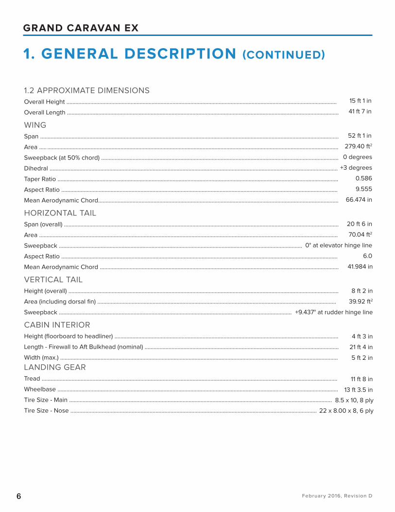
1.2 APPROXIMATE DIMENSIONS
Overall Height .....................................................................................................................................................................................
Overall Length ......................................................................................................................................................................................
WING
Span ........................................................................................................................................................................................................
Area ..... ...................................................................................................................................................................................................
Sweepback (at 50% chord) ...............................................................................................................................................................
Dihedral .................................................................................................................................................................................................
Taper Ratio ............................................................................................................................................................................................
Aspect Ratio .........................................................................................................................................................................................
Mean Aerodynamic Chord.................................................................................................................................................................
HORIZONTAL TAIL
Span (overall) ........................................................................................................................................................................................
Area ........................................................................................................................................................................................................
Sweepback ...................................................................................................................................................................
Aspect Ratio .........................................................................................................................................................................................
Mean Aerodynamic Chord ................................................................................................................................................................
VERTICAL TAIL
Height (overall) .....................................................................................................................................................................................
Area (including dorsal fi n) ................................................................................................................................................................
Sweepback ............................................................................................................................................................
CABIN INTERIOR
Height (fl oorboard to headliner) ......................................................................................................................................................
Length - Firewall to Aft Bulkhead (nominal) ..................................................................................................................................
Width (max.) ..........................................................................................................................................................................................
LANDING GEAR
Tread ......................................................................................................................................................................................................
Wheelbase ............................................................................................................................................................................................
Tire Size - Main ................................................................................................................................................................................
Tire Size - Nose .....................................................................................................................................................................
February 2016, Revision D7
GRAND CARAVAN EX
8842 lb
8807 lb
8500 lb
4558 Est. lb
4284 Est. lb
335.6 gal/2,246 lb
14 qt
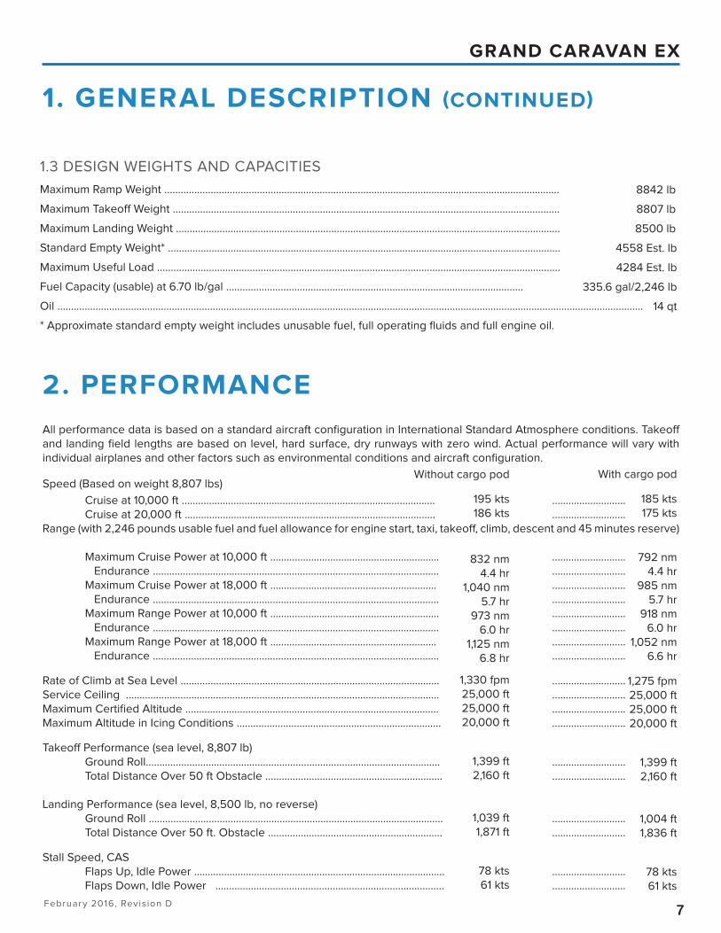
Speed (Based on weight 8,807 lbs)
Cruise at 10,000 ft ............................................................................................. ...........................
Cruise at 20,000 ft ............................................................................................ ...........................
Range (with 2,246 pounds usable fuel and fuel allowance for engine start, taxi, takeoff , climb, descent and 45 minutes reserve)
Maximum Cruise Power at 10,000 ft .............................................................. ...........................
Endurance ......................................................................................................... ...........................
Maximum Cruise Power at 18,000 ft ............................................................. ...........................
Endurance ......................................................................................................... ...........................
Maximum Range Power at 10,000 ft .............................................................. ...........................
Endurance ......................................................................................................... ...........................
Maximum Range Power at 18,000 ft ............................................................. ...........................
Endurance ......................................................................................................... ...........................
Rate of Climb at Sea Level ............................................................................................... ...........................
Service Ceiling ................................................................................................................... ...........................
Maximum Certifi ed Altitude ............................................................................................. ...........................
Maximum Altitude in Icing Conditions ........................................................................... ...........................
Takeoff Performance (sea level, 8,807 lb)
Ground Roll............................................................................................................ ...........................
Total Distance Over 50 ft Obstacle ................................................................. ...........................
Landing Performance (sea level, 8,500 lb, no reverse)
Ground Roll ............................................................................................................ ...........................
Total Distance Over 50 ft. Obstacle ................................................................ ...........................
Stall Speed, CAS
Flaps Up, Idle Power ............................................................................................ ...........................
Flaps Down, Idle Power .................................................................................... ...........................
All performance data is based on a standard aircraft confi guration in International Standard Atmosphere conditions. Takeoff
and landing fi eld lengths are based on level, hard surface, dry runways with zero wind. Actual performance will vary with
individual airplanes and other factors such as environmental conditions and aircraft confi guration.
1. GENERAL DESCRIPTION (CONTINUED)
2. PERFORMANCE
1.3 DESIGN WEIGHTS AND CAPACITIES
Maximum Ramp Weight .................................................................................................................................................
Maximum Takeoff Weight ..............................................................................................................................................
Maximum Landing Weight .............................................................................................................................................
Standard Empty Weight* ................................................................................................................................................
Maximum Useful Load ....................................................................................................................................................
Fuel Capacity (usable) at 6.70 lb/gal .............................................................................................................
Oil .......................................................................................................................................................................................................................
* Approximate standard empty weight includes unusable fuel, full operating fl uids and full engine oil.
Without cargo pod
195 kts
186 kts
832 nm
4.4 hr
1,040 nm
5.7 hr
973 nm
6.0 hr
1,125 nm
6.8 hr
1,330 fpm
25,000 ft
25,000 ft
20,000 ft
1,399 ft
2,160 ft
1,039 ft
1,871 ft
78 kts
61 kts
With cargo pod
185 kts
175 kts
792 nm
4.4 hr
985 nm
5.7 hr
918 nm
6.0 hr
1,052 nm
6.6 hr
1,275 fpm
25,000 ft
25,000 ft
20,000 ft
1,399 ft
2,160 ft
1,004 ft
1,836 ft
78 kts
61 kts
February 2016, Revision D8
GRAND CARAVAN EX
4. FUSELAGE GROUP
3. STRUCTURAL DESIGN CRITERIA
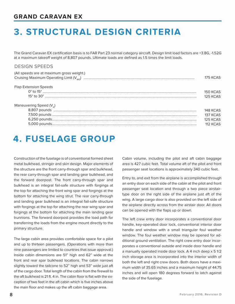
Construction of the fuselage is of conventional formed sheet
metal bulkhead, stringer and skin design. Major elements of
the structure are the front carry-through spar and bulkhead,
the rear carry-through spar and landing gear bulkhead, and
the forward doorpost. The front carry-through spar and
bulkhead is an integral fail-safe structure with forgings at
the top for attaching the front wing spar and forgings at the
bottom for attaching the wing strut. The rear carry-through
and landing gear bulkhead is an integral fail-safe structure
with forgings at the top for attaching the rear wing spar and
forgings at the bottom for attaching the main landing gear
trunnions. The forward doorpost provides the load path for
transferring the loads from the engine mount directly to the
primary structure.
The large cabin area provides comfortable space for a pilot
and up to thirteen passengers. (Operations with more than
nine passengers are limited to countries that issue approval.)
Inside cabin dimensions are 51” high and 62” wide at the
front and rear spar bulkhead locations. The cabin narrows
slightly toward the tailcone to 52” high and 53” wide just aft
of the cargo door. Total length of the cabin from the fi rewall to
the aft bulkhead is 21 ft. 4 in. The cabin fl oor is fl at with the ex-
ception of two feet in the aft cabin which is fi ve inches above
the main fl oor and makes up the aft cabin baggage area.
Cabin volume, including the pilot and aft cabin baggage
area is 427 cubic feet. Total volume aft of the pilot and front
passenger seat locations is approximately 340 cubic feet.
Entry to, and exit from the airplane is accomplished through
an entry door on each side of the cabin at the pilot and front
passenger seat location and through a two piece airstair-
type door on the right side of the airplane just aft of the
wing. A large cargo door is also provided on the left side of
the airplane directly across from the airstair door. All doors
can be opened with the fl aps up or down.
The left crew entry door incorporates a conventional door
handle, key-operated door lock, conventional interior door
handle and window with a small triangular foul weather
window. The foul weather window may be opened for ad-
ditional ground ventilation. The right crew entry door incor-
porates a conventional outside and inside door handle and
a manually operated inside door lock. A 4 inch deep x 5 1/2
inch storage area is incorporated into the interior width of
both the left and right crew doors. Both doors have a maxi-
mum width of 35.65 inches and a maximum height of 44.75
inches and will open 180 degrees forward to latch against
the side of the fuselage.
175 KCAS
150 KCAS
125 KCAS
148 KCAS
137 KCAS
125 KCAS
112 KCAS
DESIGN SPEEDS
(All speeds are at maximum gross weight.)
Cruising Maximum Operating Limit (VMO
) .............................................................................................................................
Flap Extension Speeds
0° to 15° .............................................................................................................................................................................
15° to 30° ...........................................................................................................................................................................
Maneuvering Speed (VA)
8,807 pounds .................................................................................................................................................................
7,500 pounds ...................................................................................................................................................................
6,250 pounds...................................................................................................................................................................
5,000 pounds...................................................................................................................................................................
The Grand Caravan EX certifi cation basis is to FAR Part 23 normal category aircraft. Design limit load factors are +3.8G, -1.52G
at a maximum takeoff weight of 8,807 pounds. Ultimate loads are defi ned as 1.5 times the limit loads.
February 2016, Revision D9
GRAND CARAVAN EX
The passenger entry door consists of an upper and lower
section. When opened, the upper section swings upward
and the lower section drops down providing integral
steps to aid in boarding or exiting the airplane. The door
opening is approximately 24 inches wide and 50 inches
high.
A two-piece cargo door is installed on the left side of the
airplane aft of the wing trailing edge. The cargo door is
divided into an upper and lower section. When opened,
the upper section swings upward and the lower section
opens 180 degrees forward providing a large 49 inch
wide by 50 inch high opening in the side of the fuselage
which facilitates the loading of bulky cargo into the cabin.
The door opening is fl ush with the fl oor and has square
corners for maximum cargo loading capability.
The airplane is equipped with a two-piece plexiglass
windshield reinforced with a metal center strip. Sixteen
side windows of the fi xed type are installed in the cabin
sides including one each in the two crew entry doors, two
windows in the upper section of the cargo door and one
window in the upper section of the passenger entry door.
The windshield and forward crew door windows are 5/16
inch and 1/4 inch thick respectively. All other windows are
3/16 inch thick tinted plexiglass.
4. FUSELAGE GROUP (CONTINUED)
The Grand Caravan EX utilizes conventional wings with
NACA 23000 Series Airfoils. The externally braced, fail-safe
wings are constructed of front and rear spars with formed
sheet metal ribs, doublers and stringers. The entire struc-
ture is covered with aluminum skin.
The primary wing spars, wing carry-through spars in the fu-
selage and attaching structure are of fail-safe construction
for limit fl ight loads. Fail-safe construction assures that the
structure is designed and built in such a way that should
any single structural component fail, the remaining struc-
ture is capable of carrying certifi ed limit fl ight loads.
5. WING GROUP
The empennage consists of a conventional vertical stabi-
lizer, rudder, horizontal stabilizer and elevator, all of which
are constructed of a forward and aft spar with formed sheet
metal ribs and aluminum skin panels. The horizontal stabiliz-
er contains dual jack screw type actuators for operating the
elevator trim tabs. An elevator trim tab is attached to each
elevator by full length piano-type hinges. Stabilizer abrasion
boots are installed along the leading edge of the horizontal
stabilizer.
6. EMPENNAGE GROUP
February 2016, Revision D10
GRAND CARAVAN EX
8. PROPULSION
7. LANDING GEAR
8.1 POWERPLANT
The propulsion system consists of a single fuselage mount-
ed Pratt and Whitney PT6A-140 turboprop engine. The
PT6A-140 is rated to 867 shp at 1900 rpm. The standard
time between overhaul for this engine is 3600 hours.
Conventional turboprop controls are used to operate the
engine and propeller. They consist of a power lever, emer-
gency power lever, propeller control lever and a fuel condi-
tion lever. The power and fuel condition levers are engine
controls while the propeller control lever controls propeller
speed. An emergency power lever is provided to manually
control fuel supply to the engine should a malfunction occur
in the fuel control unit.
Engine operation is monitored by the engine indication sys-
tem (EIS) which shows numeric readouts of critical engine,
fuel and electrical indications for the following: torque, pro-
peller speed, interstage temperature (ITT), gas generator %
RPM (Ng), fuel fl ow, oil pressure and oil temperature. A wet
type standby engine torque gauge is also installed. Engine
torque is limited by a sensor that reduces fuel fl ow if an over
torque occurs.
An inertial separator system is built into the engine air inlet
duct to prevent moisture particles from entering the engine
inlet plenum. The inertial separator system is mechanically
controlled by a push-pull handle located on the left side of
the instrument panel. Engine ignition is provided by two
igniters that are energized by a dual channel ignition ex-
citer mounted on the right side of the engine compartment.
Mounting provisions are provided for a standby ignition ex-
citer unit.
A P&WC FAST Engine Trend Monitor is an engine trend re-
cording device and an engine parameter exceedance moni-
tor which will allow operators to monitor the health of the
engine through periodic sampling of engine parameters.
The engine trend monitor contains logic to determine when
the aircraft is in a stable cruise fl ight regime before auto-
matically taking a trend sample. If an optional SIM card is
installed and the GSM feature is activated through P&WC
the data is automatically uploaded via built-in cell phone
transmitter after landing.
This is an advisory system only. The airplane’s engine in-
dication system is still the primary source of detecting and
correcting conditions where engine limitations are exceed-
ed. There are no additional aircraft limitations and no per-
formance change with the P&WC FAST Engine Trend Moni-
tor installed.
The landing gear is of the non-retracting, tricycle type with
a steerable nose wheel and two main wheels. Shock ab-
sorption is provided by the tubular spring steel main land-
ing gear struts with an inter-tube connecting the two outer
tubes. The tires are tube type; standard nose tire is 22 x
8.00 x 8, 6 ply and main gear tires are 8.50 x 10, 8 ply. The
nose gear tire is mounted on an extended nose gear strut
providing 14 3/4 in. ground clearance. The nose gear shock
absorption is provided by the oil snubber combined with
a drag link spring providing vertical and aft displacement
restraint. Each main gear wheel is equipped with a hydrauli-
cally actuated four piston brake.
Nose gear steering is accomplished by using the rudder
pedals which turns the nose wheel through an arc of ap-
proximately 15° each side of center. By applying either left
or right brake, the degree of turn may be increased up to
51.5° each side of center. The minimum turning radius of the
airplane, using diff erential braking and nose wheel steering
during taxiing, is 33 feet 8 inches.
February 2016, Revision D11
GRAND CARAVAN EX
9. SYSTEMS
9.1 FLIGHT CONTROLS
The Grand Caravan EX’s fl ight control system consists of
conventional aileron, elevator and rudder control surfaces.
In addition, a pair of slot lip spoilers are mounted above the
outboard ends of the fl aps. The control surfaces are manu-
ally operated through mechanical linkage using a control
wheel for the ailerons, spoilers and elevator and rudder/
brake pedals for the rudder.
The rudder control utilizes a rudder pedal cable system
driving the rudder. The fl oor mounted rudder bars are gear
interconnected to maintain cable tension. Conventional de-
sign of inner torque tubes serve to allow co-pilot operation
of the left-hand mounted brake cylinders. The brake cylin-
ders have a remote reservoir mounted on the forward side
of the engine fi rewall for convenient access.
Rudder trim system consists of a trim wheel driving a fl ex
shaft which, in turn, adjusts rudder pressure.
The elevator control system features a conventional cable
drive system. The elevator is connected to the cables by a
bellcrank and push-pull rod.
Elevator trim is accomplished through two elevator trim tabs
by utilizing the vertically mounted trim control wheel on the
control pedestal. An electric elevator trim system is avail-
able with the standard autopilot installation.
The aileron control system is a combination of cables, quad-
rants, bellcranks and push-pull rods. A push-pull rod drives
the ailerons.
An aileron trim system consists of a pedestal mounted con-
trol knob, cables, fail-safe actuator, pushrods and trim tabs.
The left aileron incorporates a servo tab while the right aile-
ron incorporates a trimmable servo tab.
A pair of slot lip spoilers mounted above the outboard ends
of the fl aps are incorporated to improve low speed roll con-
trol. The spoilers are interconnected with the aileron system
through a pushrod mounted to an arm on the aileron bell-
crank. Spoiler travel is proportional to aileron up travel.
The single slotted, semi-fowler fl aps are electrically driven
and incorporate a trailing edge angle with leading edge vor-
tex generators to reduce stall speed and provide enhanced
lateral stability. A selector and mechanical type follow-up in-
dicator is provided in the control pedestal. The fl ap system
consists of an electrically driven screwjack actuator, a pri-
mary and standby motor, and a system of cables, bellcranks
and pushrods connected to the fl aps. The standby electric
drive motor provides back-up fl ap actuation in the event of
failure of the primary motor.
8.2 PROPELLER
The Grand Caravan EX is equipped with a 106 inch diameter
metal propeller. The three-blade, constant speed, full feath-
ering, single acting, reversible pitch propeller is manufac-
tured by Hartzell, model HC-B3TN-3AF(Y). The propeller is
controlled by a propeller governor and an overspeed gover-
nor mounted on and driven by the reduction gear-box. The
overspeed governor acts as a safeguard against propeller
overspeed should the primary propeller governor fail.
8. PROPULSION (CONTINUED)
February 2016, Revision D12
GRAND CARAVAN EX
9. SYSTEMS (CONTINUED)
9.2 FUEL SYSTEM
The Grand Caravan EX fuel system consists of two vented
integral fuel tanks (one in each wing formed by the front
and rear spars), a fuel reservoir, engine fuel system, quantity
and fl ow instrumentation, and the necessary lines, controls,
valves and pumps to complete the system. Fuel system ca-
pacity is 339.1 U.S. gallons (335 gallons usable). Filling the
fuel tanks is accomplished through fi ller caps in each wing.
Normal operation is with both tanks on. The pilot can me-
chanically select fuel from either left or right fuel tanks or
both at the same time.
Fuel quantity is measured by four fuel level probes (two in
each wing tank) and indicated on the engine indication sys-
tem (EIS). The fuel quantity system is calibrated in gallons
based on 6.7 pounds per gallon. Fuel quantity indications
are displayed in pounds. Wing fuel level caution advisories,
one for each wing tank, are provided through the crew ad-
visory system (CAS). The appropriate FUEL LOW (CAS) mes-
sage will illuminate when the fuel in the respective tank is
approximately 25 gallons or less. A warning advisory is also
provided to indicate a low fuel level in the fuel reservoir
tank.
9.3 ELECTRICAL SYSTEM
The Grand Caravan EX is equipped with a 28-volt, direct-
current electrical system. The system uses a 24-volt, 38
ampere-hour sealed lead acid battery as a source of elec-
trical energy and a 200-amp engine-driven starter genera-
tor. (An optional 300-amp engine-driven starter generator is
available.) Power is supplied to most general electrical and
all avionics circuits through two general buses, two avion-
ics buses and a battery bus. The battery bus is energized
continuously for ELT reset, Hobbs Meter, cabin/courtesy light
functions and engine trend monitor processor.
A generator control unit provides the electrical control func-
tion necessary for the operation of the starter-generator.
Electrical system operation can be monitored on the Engine
Indication System (EIS) display on the MFD (in normal mode).
Battery Amps and Bus Volts can be viewed on either EIS
page (Engine or System). Generator and (Standby) Alterna-
tor Amps can be viewed on the EIS System page. The Crew
Alerting System (CAS) Annunication Window is located on
each Primary Flight Display (PFD) and can present appropri-
ate messages (i.e. warning, caution and advisory) pertaining
to various engine and aircraft systems as may be applicable.
A standard ground service plug receptacle permits the use
of an external power source for cold weather starting or dur-
ing maintenance work. Ground service circuitry is provided
to prevent the external power and the battery from being
connected together during starting, and incorporates polar-
ity reversal and overvoltage protection. The external power
receptacle is installed on the left side of the engine com-
partment near the fi rewall.
A standby electrical system is installed for use as a standby
power source in the event the main generator system mal-
functions in fl ight. The system includes a belt-driven alterna-
tor operated at a 75-amp capacity rating.
One automotive-style 12-volt power outlet is located in the
cockpit. Two cabin power outlets are also included.
9.4 LIGHTING SYSTEM
Exterior LED lighting consists of two navigation lights, two
landing lights, two taxi/recognition lights, two strobe lights,
a fl ashing beacon and two underwing courtesy lights. All
exterior lights are controlled by toggle switches located on
the lighting control panel on the left side of the instrument
panel.
The G1000 displays and bezels, the audio panel and the
autopilot control utilize either automatic or manual means
of lighting control, based on crew setting of the “Avionics”
potentiometer. The panel mounted G1000 equipment will
revert to automatic dimming using GDU bezel photocell
input when the “Avionics” knob is near the extreme CCW
position. Moving the potentiometer clockwise places the
G1000 panel equipment into manual mode of selection for
display brightness throughout the rest of its travel. Other
lighting is provided for standby instruments and other non-
G1000 avionics, pilot and co-pilot control wheel map lights,
LH, Center and RH fl ood lights, cabin/courtesy lights, pas-
senger reading lights and a no smoking/seat belt advisory
sign. All interior lighting is LED with the exception of pilot
and copilot control wheel map lights.
February 2016, Revision D13
GRAND CARAVAN EX
9. SYSTEMS (CONTINUED)
9.5 ENVIRONMENTAL SYSTEM
The temperature and volume of airfl ow to the cabin is regu-
lated by the cabin heating, ventilating and defrosting sys-
tem. In the heating system, hot engine compressor outlet air
is routed through system components to obtain the correct
air temperature before air is routed to the cabin air distribu-
tion system. Controls are provided to direct the heated air to
the forward and/or aft portions of the cabin for heating and
to the windshield for defrosting.
Outside ventilating air is obtained from an inlet on each
side of the forward fuselage and through two ram air inlets,
one on each wing at the upper end of the wing struts. The
wing ventilating air is routed through the wing into a plenum
chamber located in the center of the cabin top. The plenum
distributes the ventilating air to individual overhead outlets
at each seat position. The forward fuselage ram air inlets
provide ventilation through panel outlets to the fl ight deck.
A fan driven ventilation system provides supplemental cab-
in ventilation through two overhead mounted ventilators. An
optional air conditioning system is available that provides
comfortable cabin temperataures during hot weather op-
erations, both on the ground or in fl ight.
9.6 PITOT-STATIC SYSTEM
The left hand pitot-static system supplies ram air and static
pressure to the number one ADC (Air Data Computer) and
to the standby airspeed indicator. It also provides static
pressure to the standby altimeter. The system is composed
of a heated pitot-static tube mounted on the leading edge
of the left wing, a static pressure alternate source valve, a
drain valve located behind the instrument panel and the as-
sociated plumbing necessary to connect the instruments
and sources.
The right hand pitot-static system supplies ram air and static
pressure to the number two ADC. The system is composed
of a heated pitot-static tube mounted on the leading edge
of the right wing, a drain valve located behind the instru-
ment panel, and associated plumbing.
9.7 VACUUM SYSTEM
A vacuum system provides the suction necessary to oper-
ate the standby attitude indicator. Vacuum is obtained by
passing regulated compressor bleed air through a vacuum
ejector. The vacuum system consists of the bleed air pres-
sure regulator, a vacuum ejector, a vacuum relief valve, and
a vacuum system air fi lter. Vacuum system failure is indicat-
ed via a warning fl ag on the standby attitude indicator.
9.8 GARMIN G1000 AVIONICS SYSTEM
The integrated avionics system incorporates 3 ten-inch
displays; the pilot’s primary fl ight display (PFD), the multi-
function display (MFD) and the co-pilot’s PFD. The system
includes a single audio system control panel and a separate
autopilot controller.
The fully integrated Garmin G1000 system will provide the
following communication/navigation/surveillance (CNS)
functions: Dual VHF NAV/Glideslope/Localizer receivers,
dual VHF com transceivers, dual WAAS GPS receivers and
Mode S Transponder. The KN-63 DME can be selected to
either NAV1 or NAV2 via PFD softkeys. Crew alerts are dis-
played on the PFDs.
The automatic fl ight control system (AFCS) incorporates a
GFC-700 three-axis autopilot with pitch trim and GFC-710
autopilot controller.
Avionics cooling is provided by two cowl deck fans and
three display fans. The cowl deck fans are powered from
the electrical bus. The display fans provide cooling air to
each of the three display units and are powered from the
display power circuits.
Avionic circuit breakers are located on an exclusive panel
located on the lower left-hand instrument panel.
February 2016, Revision D14
GRAND CARAVAN EX
10. FLOATPLANE
The Grand Caravan EX fl oatplane provisions consist of hoist-
ing rings, inboard fuel fi lling ports, extended chord rudder,
short airstair door cables (loose equipment), and microphone
relocation.
The hoisting rings include four rings which attach to the left
and right sides of both the front and rear spar wing-to-fuse-
lage attach fi ttings. To gain access to the hoisting rings, it
is necessary to remove the wing-to-fuselage fairing strips.
Inboard fuel ports with anti-siphon doors provide an easily
accessible fuel fi ller location when refueling on fl oats. Due
to wing dihedral, use of inboard fi ller ports for refueling will
reduce maximum usable fuel to 240 gallons. The extended
chord rudder increases the surface area of the rudder to pro-
vide greater control when fl oats are installed on the aircraft.
The hand microphone is located on the center pedestal to al-
low clearance for the emergency lever that is used to manu-
ally lower the wheels on the fl oats.
WIPLINE 8750 FLOAT INSTALLATION
The Caravan can be converted to a fl oatplane or an amphib-
ian when equipped with Wipline 8750 Series Floats manufac-
tured, installed, and warranted by Wipaire, Inc. (The optional
300-amp starter/generator is not compatible with this instal-
lation.)
The fl oats are part of a Wipaire, Inc. STC and are installed
by Wipaire, Inc. after aircraft acceptance and delivery from
Cessna Aircraft Company. Wipline fl oats are FAA certifi ed and
TSO approved, and meet Federal CAR-3.372 buoyancy regu-
lations for fl ooded compartments.
For additional information contact:
Wipaire, Inc.
1700 Henry Avenue, Fleming Field,
South St. Paul, MN 55075
(651) 451-1205
(651) 457-7875 fax
http//www.wipaire.com.
February 2016, Revision D15
GRAND CARAVAN EX
10. FLOATPLANE (CONTINUED)
The Following Performance Figures Are Provided By Wipaire, Inc. And Have Not Been Tested By Cessna Aircraft Company.
SPECIFICATIONS FOR THE 8750 AMPHIBIOUS FLOAT
DIMENSIONS (EXTERNAL)
Length (nose of fl oat to extended water rudder) ...........................................................................................................................
Height - hull .............................................................................................................................................................................................
Width - hull ...............................................................................................................................................................................................
WEIGHT
Amphibious 8750 on the Cessna 208B Grand Caravan EX ........................................................................................
*Exchange = Float installation weight minus aircraft landing gear weight.
PERFORMANCE FOR THE 8750 AMPHIBIOUS FLOAT - CESSNA 208B GRAND CARAVAN EX
PT6A-140 (867 HP)
Cruise Speed (75%) ...............................................................................................................................................................................
Take off run (land) ..................................................................................................................................................................................
Take off over 50 ft. obstacle (land) ....................................................................................................................................................
Take off run (water) ................................................................................................................................................................................
Take off over 50 ft. obstacle (water) ..................................................................................................................................................
Rate of climb ...........................................................................................................................................................................................
Service ceiling .........................................................................................................................................................................................
Gross weight (land & water) Requires Wipaire Gross Weight Kit STC ......................................................................................
Landing weight (land) Requires Wipaire Gross Weight Kit STC .................................................................................................
Landing weight (water) Requires Wipaire Gross Weight Kit STC ...............................................................................................
Maximum take off weight .....................................................................................................................................................................
Maximum range* (cruise speed, 10,000 ft) ......................................................................................................................................
Stall speed (landing confi guration) ....................................................................................................................................................
Standard Empty Weight (Estimated) .................................................................................................................................................
Maximum Useful Load (Estimated) ....................................................................................................................................................
*Range based on 332 gal. usable fuel and includes takeoff , climb, descent and 45 minute reserve.
31’-9”
3’-3”
3’-6”
1,678 lbs/1,142 lbs*
159 KTAS
1,826 ft
2,425 ft
2,000 ft
3,270 ft
1,212 ft/min
20,000 ft
9,062 lbs
9,062 lbs
9,062 lbs
9,062 lbs
820 nmt
59 KCAS
Amphibian
5,800 lbs
3,262 lbs
February 2016, Revision D16
GRAND CARAVAN EX
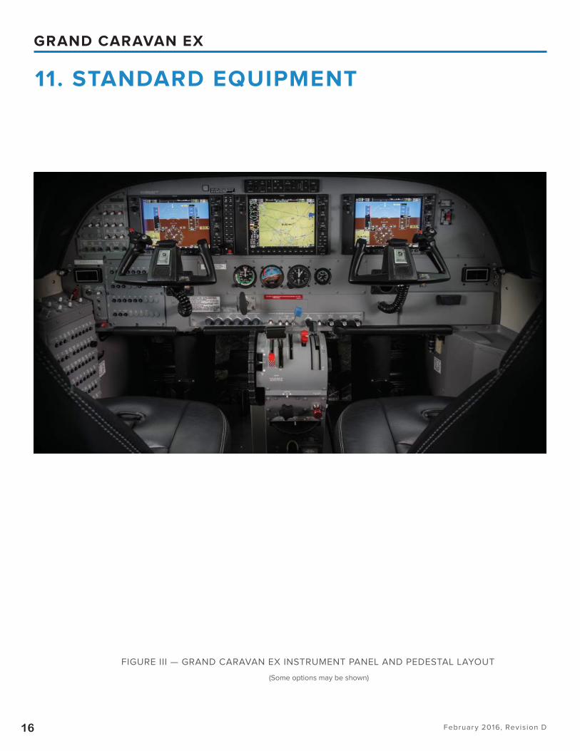
FIGURE III — GRAND CARAVAN EX INSTRUMENT PANEL AND PEDESTAL LAYOUT
11. STANDARD EQUIPMENT
(Some options may be shown)
February 2016, Revision D17
GRAND CARAVAN EX
11. STANDARD EQUIPMENT (CONTINUED)
11.1 AVIONICS
Standard Avionics Kit (includes Two Headsets)
Garmin G1000 System includes:
GDU 1040A Pilot & Co-Pilot Primary Flight Display (PFD)
GDU 1040A Multi Function Display (MFD)
GDC 74A Dual Air Data Computer (ADC)
GEA 71 Engine/Airframe Unit
GIA 63W Dual Integrated Avionics Unit (Includes Comm,
Nav, GPS)
GRS 77 Dual Attitude and Heading Reference System
(AHRS)
GMA 1347 Single Audio System with Integrated Marker
Beacon Receiver
GMC 710 Autopilot Mode Controller
GSA 80/81 Servo Actuators with GSM 86 Servo Mounts
GTX 33 Mode S Transponder
Garmin Relative Terrain/Obstacles
Garmin Flight Charts Capable
Garmin Safe Taxi Capable
KN-63 DME
Switch, Avionics Power (Two) (On-Off )
Artex ME-406 2-Frequency (Non -Nav Interfaced) ELT with
Remote Switch and Monitor Light (Dorsal Fin Installation)
Avionics Cooling, (2) cowl deck fans and (3) display fans
PA System with Aft Cabin Speakers
Intercom
Cabin Headset Jacks
11.2 ENGINE INDICATION SYSTEM (EIS)
Displayed on MFD During Normal Operations:
Engine and System Displays - Show numeric readouts of
critical engine, fuel and electrical indications and calcula-
tions for the following:
Torque
Interstage Turbine Temperature
Gas Generator Speed
Propeller Speed
Oil Pressure
Oil Temperature
Fuel Quantity
Fuel Flow
Ammeter/Voltmeter
Standby Engine Instrument
Engine Torque Gauge, Wet Type
Digital FAST Engine Trend Monitoring System
11.3 FLIGHT INSTRUMENTS
Indications Displayed on each PFD:
Airspeed
Attitude with Slip/Skid Indication
Altitude
Vertical Deviation, Glideslope and Glidepath
Vertical Speed
Horizontal Situation Indication
Outside Air Temperature
System Time
Generic Timer
Wind Data
Standby Flight Instruments:
Airspeed Indicator
Attitude Gyro
Altimeter
Magnetic Compass,
Heated Pitot System, Pilot & Co-Pilot
Alternate Static Source
Static Source Drains
Instrument Static System
Second Independent Pitot-Static System
11.4 FLIGHT CONTROLS
Brake, Parking
Brakes, Hydraulic, Toe-Operated
Control Cables — Corrosion Resistant Steel
Control Lock, Ailerons and Elevator
Flight Control System, Pilot & Co-Pilot (Includes All-Pur-
pose Control Wheel, Pedals and Toe Brakes)
Friction Lock, Engine Controls
Powerplant, Quadrant Type Controls:
Condition Lever
February 2016, Revision D18
GRAND CARAVAN EX
Primary Engine Power
Back-Up Engine Power, (Emergency Power Lever)
Propeller, Speed and Feather
Rudder Gust Lock
Trim System (Aileron/Rudder (Manual), Elevator (Manual &
Electric Pilot & Co-Pilot)
Wing Flaps, Electric Pre-Select with Standby Motor
11.5 ENVIRONMENTAL
Defroster, Windshield (Pilot and Copilot)
Heating System, Cabin (Bleed Air Type)
Soundproofi ng
Ventilation System, Cockpit (Ram Air)
Ventilator, Adjustable, Cabin Air
Ventilation System, Fan Driven
11.6 ELECTRICAL POWER
Battery, 24 Volt, 38 Amp/Hr, Sealed Lead-Acid
Battery Switch (On-Off )
Circuit Breakers, Electrical
Generator Control Unit
Generator Switch (Trip-On-Reset)
Ground Service Plug Receptacle
Starter/Generator, 200 Amp
Power Outlet, 12V Cockpit And Cabin
Standby Electrical System, 75 amp
11.7 EXTERIOR LIGHTS (LED)
Beacon – Omni Flash (Red)
Courtesy, Under Wing
Landing, L.H. and R.H. (Wing Leading Edge-Outboard)
Navigation (2)
Strobe (2) Wing Tip Mounted
Taxi, L.H. and R.H. (Wing Leading Edge-Inboard)
Ice Detection
11.8 INTERIOR LIGHTS (LED)
LED Backlit Instrument Panel Lighting
Map Light, Control Wheel Mounted, Pilot & Co-Pilot (Vari-
able Intensity)
Overhead Courtesy (4) (Forward and Mid Cabin, Cargo
Door and Passenger Door)
Overhead Flood (Pilot and Copilot) (3)
Passenger Reading Lights (14)
Dimming Controls, Switch Panel, Avionics Circuit Breaker
Panel, Left Hand Panel & Environmental Panel
11.9 POWERPLANT
Chip Detector Installation
Cowling, Rigid-Mounted (Quick Removable) Lower and
Easily Openable Upper Sides
Cowl Locks
Engine Inlet Cover (2) and Propeller Tie-Down Sleeve
Engine, Turboprop PT6A-140, 867 SHP, 3600 TBO
Engine Wash Ring (Integral)
Engine Support, Vibration Isolation
Filter, Integral, Full Flow Oil
Fire Detection System, Engine Compartment
Ignition System Exciter Unit Mounting (Provisions for
Mounting Standby Unit)
Ignition System (Dual Ignitors)
Intake Inertial Separator (Manual)
Oil Cooler, High Capacity
Overspeed Governor
Propeller, 3 Blade Aluminum, Constant Speed, Full Feath-
ering, Reversible – Hartzell
Propeller Governor
Propeller Spinner (Polished)
Shielding, Engine Ignition
Shutdown Fuel Collector, Engine
Oil Sight Gage
11.10 FUEL SYSTEM
Fuel Boost Switch, Auxiliary
Fuel Caps with Anti-Siphon Doors
Fuel Control Heater, Engine
Fuel Filter with Quick Drain
Fuel Low Level Warning System
Fuel Pump, Auxiliary (Electric)
Fuel Pump, Engine
Fuel Reservoir with Quick Drain
11. STANDARD EQUIPMENT (CONTINUED)
February 2016, Revision D19
GRAND CARAVAN EX
11. STANDARD EQUIPMENT (CONTINUED)
Fuel Selector Valves
Fuel Shutoff Valve
Fuel Tanks
Fuel Valves, Quick Drain (8)
Fuel Vents, Non-Icing
Fuel Sampler Cup
11.11 INTERIOR
Aircraft Keys
Approach Plate Holder, L.H. & R.H.
Baggage Area Partition Net
Baggage Tie-Down Straps (4)
Beverage Cup Holders (Pilot and Copilot)
Cargo Tie-Down Fittings Provisions
Cargo Tie-Down Fittings (Baggage Area)
Checklist, Pilot’s (Laminated)
Crew Door Storage Area RH, LH
Fire Extinguisher Cabin– Hand Type
Floor Covering, Lightweight Vinyl
Glareshield
Handbook, Customer Care, Includes Engine/Flight Logs,
Warranty, Etc.
Handbook, Pilot’s Operating
Headliner – Vinyl
Instrument Panel – Metal
Map/Glove Compartment
Oxygen System, Partial Installation (Consists of Diffi cult to
Install Plumbing)
Pilot and Co-pilot Restraint – Integral 5 Point Lap and
Shoulder Harness with Inertial Reel
Pilot’s LH Pre-Flight Assist Handle
Plotter, Weight & Balance (Cargo & Passengers)
Pockets, Map and Storage
Recorder, Flight Hour
Seats, Pilot & Copilot, Adjustable Fore, Aft and Vertical with
Articulating Recline and Arm Rest
Sign, Fasten Seat Belts & No Smoking
Step, Cabin Entrance, Retractable (RH & LH Crew Entry
Doors)
Sunvisors
Window, Foul Weather, Pilot Door
Windows Tinted All-Around
11.12 EXTERIOR
Anti-Precipitation Static Kit
Bonding Straps, Control Surface (Aileron, Elevator and
Rudder)
Cargo Pod Provisions with Twisted Stack
Corrosion Proofi ng, External
Door, Cargo, Two-Piece (Left Side of Aircraft, with Upper
Door Unlocked Annunciator Light)
Door, Copilot (Full Opening)
Door, Pilot (Full Opening)
Door, Passenger with Airstair Feature (Right Side of Aircraft
with Upper Door Unlocked Annunciator Light)
Jack Points (Fuselage and Main Landing Gear)
Landing Gear, Fixed, Nose, Steerable
Landing Gear, Fixed, Main
Lock, Key-Operated (One Key Fits All Doors)
Paint, All Over (Modifi ed Polyurethane)
Stabilizer Abrasion Boots
Stall Warning System, Heated
Tailstand
Tires, Tube Type, 8.50 x 10, 8 ply Main; 22 x 8.00, 6 ply
Nose With Extended Nose Gear Fork
Tie-Down Rings, Aircraft
Tow Bar
February 2016, Revision D20
GRAND CARAVAN EX
U.S. Standard Airworthiness Certifi cate, FAA8100-2; Export
Certifi cate of Airworthiness, FAA8130-4 or Special Airwor-
thiness Certifi cate FAA8130-7 as appropriate;
Equipment List
Weight and Balance Report
Garmin Cockpit Reference Guide
Pilot’s Operating Handbook and FAA Approved
Airplane Flight Manual
Pilot’s Abbreviated Checklist
Log Books (Aircraft and Engines)
Additional Miscellaneous Information Concerning Engine
and Airframe Support
Passenger Briefi ng Cards
Cessna CESCOM Instruction Manual
CESSNA TECHNICAL INFORMATION
Cessna makes available a complete system of manuals and
catalogs for the operation and maintenance of the Grand
Caravan EX. All Cessna and related technical information,
as well as revision information, is listed on www.cessnasup-
port.com.
Cessna manuals are kept current through periodic revi-
sions. Aircraft operators and designated maintenance
facilities can receive these revisions, by various mediums,
through a subscription service. The subscription is free for
the fi rst year to owners of new aircraft. A subscription fee
is charged thereafter.
The following manuals are provided by your choice of DVD,
Download, Online or iPad mobile app with the purchase of
a new Caravan:
Service Maintenance Manual
Illustrated Parts Catalog
Wiring Diagram Manual
Structural Repair Manual
Service Bulletins
Avionics Wiring Diagram (custom diagram of the actual
avionic installation)
CesNav Weight and Balance Calculator (CLCalc)
*Please note: for download, online and mobile app – these
publications are Windows based and registration with www.
cessnasupport.com is required. Up to four additional user
access’ available.
The following materials provided by Pratt & Whitney
Canada:
Combined Engine Maintenance Manual & Illustrated
Parts Catalog CD
One set Engine Service Bulletins Including Spare Parts
Bulletins and Service Information Letters (Paper)
Free revisions coverage for one year
Service Bulletins are also available by on-line or
email subscription at www.pwc.ca or through the
Pratt & Whitney Help Desk at (800) 268-8000.
CESSNA REVISION STATUS CHECKLIST
The Revision Status Checklist is used to verify that only the
most current Cessna maintenance and aircraft publications
are in use. The checklist is available online at www.cessna-
support.com.
PILOT’S OPERATING HANDBOOK
Revisions to the Pilot’s Operating Handbook will be mailed
periodically to the registered aircraft owner on fi le.
CESSNA OWNER ADVISORY
Cessna Owner Advisories provide owners of Cessna aircraft
up-to-the-minute information about mandatory and benefi -
cial service requirements and the latest in product improve-
ments. Owner Advisories summarize new Service Bulletins
or Service Newsletters and indicate any action required by
the owner, the time required for the owner to comply, and
the existence of any associated “credit allowances.”
Cessna Owner Advisories are mailed automatically to
owners of U.S. registered Cessna aircraft using the latest
name and address provided to the FAA. Owner Advisories
can be mailed to a diff erent address by request, provide
the subject aircraft is still covered by Cessna warranty.
International owners of Cessna aircraft covered by Cessna
warranty receive Owner Advisories through a complimen-
tary subscription. After warranty expiration, international
subscriptions are available, although a subscription fee will
be charged.
Cessna aircraft owners may register, for free, with www.
cessnasupport.com to obtain a login that allows access to
PDF versions of Service Bulletins and Newsletters. Weekly
email notifi cation of released service information is avail-
able with registration to the site.
12. DOCUMENTATION AND TECHNICAL PUBLICATIONS
February 2016, Revision D21
GRAND CARAVAN EX
COMPUTERIZED MAINTENANCE RECORD
SERVICE
Seller will provide a computerized maintenance record
service for one (1) full year from the date of delivery of a
Grand Caravan EX to the purchaser. Currently, this service
is provided by CAMP Systems International, Inc.
This service will provide owners and operators with the
reports necessary for the effi cient control of maintenance
activities. It will provide an accurate and simple method of
keeping up with aircraft components, inspections, service
bulletins and airworthiness directives while providing per-
manent aircraft records of maintenance performed.
Reports will be available which refl ect the aircraft status, up-
coming scheduled maintenance and a recap of the previous
month’s reported maintenance activity. Semi-annual reports
concerning projected annual maintenance requirements,
component removal history and fl eet-wide component reli-
ability will also be available.
The on-line system is the standard service, however, a pa-
per service is available at an additional charge. The on-line
system is accessible using a local computer with Internet
capability. Data is electronically transferred through Internet
connections between the customer and CAMP on a regular
basis to keep information up-to-date at both locations. In
addition to the standard reports, customer specifi c reports
and maintenance records can be generated at the local
computer whenever the customer wishes.
CARAVAN INSPECTION PROGRAM
The Caravan Inspection Program is task based, integrating
all inspections into an easy to follow sequence. The ben-
efi ts of the old Phase Card program are now available to all
customers.
FLIGHT-DATA ACQUISITION, STORAGE,
AND TRANSMISSION (FAST)
Cessna has chosen the FAST system as standard equip-
ment on the Caravan to allow operators to easily monitor
and maintain the aircraft engine.
The FAST system records engine parameters, indicated
airspeed, pressure altitude, outside air temperature, fl ight
hour meter, battery voltage, and the positions of the par-
ticle separator, emergency power lever and bleed air cabin
heat switch.
Data is uploaded to P&WC data analysis servers automati-
cally by GSM cell phone signal upon engine shutdown if a
SIM card is installed and the GSM subscription service is ac-
tivated through P&WC. Otherwise data can be uploaded to
P&WC data analysis servers via a supplied USB cable con-
nected to a laptop. The P&WC WebECT (tm) website formats
the data into customized reports for use as analysis tools.
13. MAINTENANCE PROGRAMS
February 2016, Revision D22
GRAND CARAVAN EX
14. LIMITED WARRANTIES
The standard Grand Caravan EX Aircraft Limited Warranty
which covers the aircraft, other than the Pratt & Whitney
Canada (P&WC) engine and associated engine accessories,
the Honeywell avionics, and the Hartzell propeller which are
warranted separately, is set forth below. Seller specifi cally
excludes vendor subscription services and the availability
of vendor service providers for Optional and Customer Re-
quested Equipment (CRQ) from Seller’s Limited Aircraft War-
ranty. Following Seller’s Limited Warranty, the engine and
engine accessory warranty of P&WC, the avionics warranty
of Honeywell, and the propeller warranty of Hartzell are
set forth. All warranties are incorporated by reference and
made part of the Purchase Agreement. All warranties are
administered by Seller’s Warranty Department.
14.1 CESSNA GRAND CARAVAN EX
LIMITED WARRANTY (LIMITED WARRANTY)
Seller expressly warrants each new Grand Caravan EX Air-
craft (exclusive of engine and engine accessories supplied
by P&WC, avionics supplied by Honeywell, and the propel-
ler supplied by Hartzell which are covered by their separate
warranties), including other factory-installed avionics and
other factory-installed optional equipment to be free from
defects in material and workmanship under normal use and
service for the following periods after delivery:
(a) One (1) year unlimited hours OR two (2) years /1,000 hour
limit on all aircraft components manufactured by Seller;
(b) Five years or 5,000 operating hours, whichever occurs
fi rst, for Garmin avionics;
(c) One year for all Optional Avionics;
(d) One year for Actuators, Brakes, GCUs, Starter Genera-
tors, Valves, Windshields, and Vendor items including en-
gine accessories supplied by Seller unless otherwise stated
in the Optional Equipment and Selection Guide;
(e) One year for CRQs, Interior Components, Interior Fur-
nishings, and Paint.
Any remaining term of this Limited Warranty is automatically
transferred to subsequent purchasers of the aircraft.
Seller’s obligation under this Limited Warranty is limited to
repairing or replacing, in Seller’s sole discretion, with ex-
change, overhauled, or new parts, any part or parts which:
(1) fail within the applicable warranty period, (2) are returned
at the warranty recipient’s expense to the facility where
the replacement part is procured, whether through Seller
Service Parts & Programs or a service facility authorized by
Seller to perform service on the aircraft (collectively “Sup-
port Facility”), (3) are accompanied by a properly executed
claim form, and (4) are found by Seller or its designee to be
defective.
Replacement parts must be procured through a Support Fa-
cility and are only warranted for the remainder of the appli-
cable original aircraft warranty period. A new warranty pe-
riod is not established for replacement parts. The repair or
replacement of defective parts under this Limited Warranty
will be made by a service facility authorized by Seller to per-
form service on the aircraft (“Authorized Service Facility”)
without charge to the warranty recipient for parts and/or la-
bor for removal, installation, and/or actual repair of such de-
fective parts. All expedited freight, transportation expenses,
import duties, customs brokerage fees, sales taxes, and use
taxes, if any, on such warranty repairs or replacement parts
are the warranty recipient’s sole responsibility. (Location of
Authorized Service Facilities will be furnished by Seller on
request.)
This Limited Warranty applies to only items detailed herein
which have been used, maintained, and operated in accor-
dance with Seller and other applicable manuals, bulletins,
and other written instructions. However, this Limited War-
ranty does not apply to items that have been subjected to
misuse, abuse, negligence, accident, or neglect; to items
that have been installed, repaired, or altered by repair fa-
cilities not authorized by Seller; or to items that, in the sole
judgment of Seller, have been installed, repaired, or altered
by other than Authorized Service Facilities contrary to ap-
plicable manuals, bulletins, and/or other written instructions
provided by Seller so that the performance, stability, or re-
liability of such items are adversely aff ected. This Limited
Warranty does not apply to normal maintenance services
(such as engine adjustments, cleaning, control rigging,
brake and other mechanical adjustments, and maintenance
February 2016, Revision D23
GRAND CARAVAN EX
inspections); or to the replacement of service items (such
as brake linings, lights, fi lters, hoses, belts, tires, and rub-
ber-like items); or to normal deterioration of appurtenances
(such as paint, cabinetry, and upholstery), corrosion or struc-
tural components due to wear, exposure, and neglect.
WITH THE EXCEPTION OF THE WARRANTY OF TITLE
AND TO THE EXTENT ALLOWED BY APPLICABLE LAW,
THIS LIMITED WARRANTY IS EXPRESSLY IN LIEU OF ANY
OTHER WARRANTIES, EXPRESSED OR IMPLIED, IN FACT
OR BY LAW, APPLICABLE TO THE AIRCRAFT. SELLER
SPECIFICALLY DISCLAIMS AND EXCLUDES ALL OTHER
WARRANTIES, INCLUDING, BUT NOT LIMITED TO, ANY
IMPLIED WARRANTY OF MERCHANTABILITY OR FIT-
NESS FOR A PARTICULAR PURPOSE. THE AFOREMEN-
TIONED REMEDIES OF REPAIR OR REPLACEMENT ARE
THE ONLY REMEDIES UNDER THIS LIMITED WARRANTY.
SELLER EXPRESSLY AND SPECIFICALLY DISCLAIMS ALL
OTHER REMEDIES, OBLIGATIONS, AND LIABILITIES, IN-
CLUDING, BUT NOT LIMITED TO, LOSS OF AIRCRAFT
USE, LOSS OF TIME, INCONVENIENCE, COMMERCIAL
LOSS, LOSS OF PROFITS, LOSS OF GOODWILL, AND
ANY AND ALL OTHER CONSEQUENTIAL AND INCIDEN-
TAL DAMAGES. SELLER NEITHER ASSUMES NOR AU-
THORIZES ANYONE ELSE TO ASSUME ON ITS BEHALF
ANY FURTHER OBLIGATIONS OR LIABILITIES PERTAIN-
ING TO THE AIRCRAFT NOT CONTAINED IN THIS LIM-
ITED WARRANTY. THIS LIMITED WARRANTY SHALL
BE CONSTRUED UNDER THE LAWS OF THE STATE OF
KANSAS AND ANY DISPUTES AND/OR CLAIMS ARISING
THERFROM SHALL BE EXCLUSIVELY RESOLVED IN THE
STATE AND/OR FEDERAL COURTS LOCATED IN WICHI-
TA, KANSAS. THE PARTIES HERETO CONSENT TO PER-
SONAL JURISDICTION IN THE FORUM CHOSEN.
14.2 PRATT & WHITNEY CANADA INC. (AB-
BREVIATED NEW ENGINE WARRANTY)
Pratt & Whitney Canada Inc. (P&WC) warrants that each
new PT6A-140 engine complete with installed accessories
at time of delivery will be free from defects in material and
manufacture. P&WC’s liability and purchaser’s remedy un-
der this warranty are limited to the repair or replacement
at P&WC’s option of goods returned to P&WC or to a loca-
tion designated by P&WC which are shown to P&WC’s rea-
sonable satisfaction to have been defective, provided that
written notice of defect shall have been given by Purchaser
to P&WC or its designee within one thousand (1,000) fl ying
hours after delivery of the engine to the fi rst user. The repair
or replacement of defective goods under the Warranty will
be made by P&WC or its designee without charge for parts
or reasonable labor for removal, installation and/or actual
repair of such defective goods, and reasonable transpor-
tation charges, except import duties, sales or use taxes, if
any, on replacement. Transportation charges for the return
of defective goods to P&WC or its designee and their re-
shipment to Purchaser and the risk of loss thereof will be
borne by P&WC.
THE FOREGOING WARRANTIES ARE EXCLUSIVE AND
ARE GIVEN AND ACCEPTED IN LIEU OF ANY AND ALL
OTHER WARRANTIES, EXPRESSED OR IMPLIED, IN-
CLUDING WITHOUT LIMITATION THE IMPLIED WAR-
RANTY OF MERCHANTABILITY AND ANY OBLIGATION,
LIABILITY, RIGHT, CLAIM OR REMEDY IN CONTRACT OR
TORT WHETHER OR NOT ARISING FROM P&WC’S NEG-
LIGENCE, ACTUAL OR IMPUTED. THE REMEDIES OF THE
PURCHASER FOR ANY BREACH OF WARRANTY SHALL
BE LIMITED TO THOSE PROVIDED HEREIN TO THE EX-
CLUSION OF ANY AND ALL OTHER REMEDIES INCLUD-
ING, WITHOUT LIMITATION, INCIDENTAL OR CONSE-
QUENTIAL DAMAGES. NO VARIATION OR EXTENSION
OF THE FOREGOING WARRANTIES, REMEDIES OR THIS
LIMITATION WILL BE BINDING UPON P&WC UNLESS AP-
PROVED IN WRITING BY A DULY AUTHORIZED OFFICER
OF P&WC.
The above abbreviated warranty is for the purposes of
the Specifi cation and Description. For complete details of
the PT6A-140 engine warranty, please refer to P&WC’s full
PT6A-140 warranty policy.
14.3 HONEYWELL/BENDIX/KING
WARRANTY
A. General Aviation Avionic products manufactured by Honeywell/Bendix/King, General Aviation Division (collec-tively referred to herein as “Honeywell/Bendix/King”) are warranted against defects in design, material or workman-ship caused by Honeywell/Bendix/King or its authorized agent(s) for the Warranty Period as defi ned in Paragraph
14. LIMITED WARRANTIES (CONTINUED)
February 2016, Revision D24
GRAND CARAVAN EX
(B) of this statement which occur under normal and intend-ed use and service, subject to all of the qualifi cations and conditions hereinafter stated.
1. Warranty coverage is only offered to purchasers who make warranty registrations within eighteen (18) months of the product’s factory shipping date. Demonstration or stock aircraft usage is restricted to 100 hours service prior to warranty registration. Warranty coverage, therefore, may be unavailable or limited, depending upon the usage or time the product in question may have remained unsold in the custody of the O.E.M. (Original Equipment Manufac-turer), his agent, or the retail dealer, a matter as to which the seller is expected to maintain accurate records and provide same, upon demand, to any purchaser or Honey-well/Bendix/King.
2. Warranty coverage for products otherwise not eligible by reason of expiration of the eighteen (18) month period specifi ed above may again become eligible for warranty protection, provided (a) that warranty registration occurs within thirty (30) months of the product’s factory shipping date and (b) that the products are submitted to Honeywell/Bendix/King for inspection and certifi cation and then the promulgated Honeywell/Bendix/King certifi cation fee is paid.
B. The Warranty Period for products shall begin upon the date of delivery of the product to the purchaser and shall end two years thereafter.
C. Any product Honeywell/Bendix/King fi nds to be in viola-tion of the warranty as set out in Paragraph (A) hereof, at the option of Honeywell/Bendix/King, shall be repaired, replaced, or exchanged, in accordance with the following procedures:
1. Products shall be returned to an authorized Honeywell/Bendix/King Service Center or Honeywell/Bendix/King Regional Product Support Repair/Overhaul Facility, with transportation charges prepaid.
2. After correction, the products shall be returned to the purchaser with surface transportation charges prepaid, except for returns to purchasers in foreign countries.
3. The risk of loss or damage to all products in transit shall be borne by the party initiating the transportation of such products unless the purchaser makes a request for a spe-cifi c mode of transportation. In such case, the risk of loss and the cost of shipment shall be borne by the purchaser.
All items repaired or replaced hereunder shall be warrant-ed for the unexpired portion of the original Warranty Period.
D. This warranty specifi cally excludes defects which Hon-eywell/Bendix/King determines to be the result of:
1. Abuse, accident, or misuse;
2. Contamination, negligence, tampering, or improper stor-age or maintenance;
3. Repair or attempted repair by unauthorized persons or use of non-Honeywell/Bendix/King or unauthorized repair or replacement parts; or
4. Products not installed by an authorized Honeywell/Ben-dix/King Installation Facility in accordance with the appro-priate installation manual.
E. The Warranty as set out in paragraph (A) is the only warranty for Honeywell/Bendix/King General Aviation Avi-onics Products and is in lieu of all other warranties express or implied, including the implied warranties of merchant-ability and fi tness for a particular purpose which are here-with expressly excluded and disclaimed.
F. The remedies as set out in Paragraph (C) hereof state the entire liability of Honeywell/Bendix/King and constitute the sole and exclusive remedy of the purchaser. Honey-well/Bendix/King shall not be liable for any other claim, loss, or damage, including, but not limited to incidental, consequential, or other kinds of damages whether based on contract, tort, negligence, or other theory of product li-ability.
G. Honeywell/Bendix/King reserves the right to make de-sign changes, additions to, and improvements in its prod-ucts without the obligation to install same in products previ-ously manufactured.
14. LIMITED WARRANTIES (CONTINUED)
February 2016, Revision D25
GRAND CARAVAN EX
14.4 HARTZELL PROPELLER
A. COVERAGE PROVIDED
Products Other Than De-Ice Boots
Hartzell Propeller Inc. (“Hartzell”) warrants to the original re-
tail purchaser (the “Purchaser”) that it will repair or replace
defects in material or workmanship in the components of a
product manufactured by Hartzell, other than a de-ice boot,
for a period of one (1) year from the date the product is fi rst
placed into service, or for the fi rst 1000 operating hours of
use of the product, whichever occurs fi rst, subject to the
other terms and conditions of this limited warranty.
De-Ice Boots
Hartzell warrants to the Purchaser that it will repair or re-
place defects in material or workmanship in the compo-
nents of a de-ice boot manufactured by Hartzell, for a pe-
riod of eighteen (18) months from the date the de-ice boot is
fi rst placed into service, or for the fi rst 2000 operating hours
of use of the product, whichever occurs fi rst, subject to the
other terms and conditions of this limited warranty.
All of the products identifi ed above are hereinafter referred
to as the “Products,” and their components hereinafter re-
ferred to as “Components.”
B. DISCLAIMER OR LIMITATION OF WARRANTIES
Unless prohibited by applicable law, and except for the
limited warranties set forth above, Hartzell hereby dis-
claims any and all express and implied warranties, includ-
ing but not limited to implied warranties of merchant-
ability and fi tness for a particular purpose. In the event
disclaimer of implied warranties is not permitted under
applicable law, such implied warranties, including but not
limited to implied warranties of merchantability and fi t-
ness for a particular purpose, are limited in duration and
in scope of coverage to the duration and scope of cover-
age of the limited warranty.
Some states do not allow limitations on how long an im-
plied warranty lasts, so above limitation may not apply to
you.
C. TERMS AND CONDITIONS OF LIMITED WARRANTY
COVERAGE
In order to obtain coverage under Hartzell’s limited warran-
ty, the Purchaser must notify Hartzell in writing of the war-
ranty claim as soon as possible after obtaining knowledge
of the potential claim, and in any event not later than ten (10)
days following expiration of the limited warranty. Hartzell
may withhold warranty repairs pending proof from Purchas-
er of the date the Product was placed into service, including
a fully completed warranty registration card. Hartzell shall
provide warranty repair or disposition instructions based on
a written statement from the Purchaser describing the al-
leged defect. All initial transportation and handling charges
must be prepaid by the Purchaser until warrantability is de-
termined by Hartzell, at which time Hartzell may reimburse
none, some, or all of these charges, at Hartzell’s discretion.
In the event Hartzell determines, at its sole discretion, that
the Product or Component thereof is covered under the lim-
ited warranty, Hartzell shall, at its election, either:
(1) Have the Product or Component repaired and returned
to Purchaser;
(2) Deliver to Purchaser a replacement Product or Compo-
nent; or
(3) Issue a credit to the Purchaser in the amount of the actu-
al purchase price for the Product. Hartzell reserves the right
to replace Products or Components with remanufactured
or re-designed Products or Components of substantially
equivalent quality. All warranty repair work will be accom-
plished at Hartzell’s principal place of business, a Hartzell
Recommended Service Facility, or a third-party location pre-
approved in writing by Hartzell.
In the event Hartzell determines that the alleged defect is
not covered by the limited warranty, the Product or Compo-
nent will be returned to Purchaser, as is, transportation and
handling charges collect. The only remedies under this lim-
ited warranty are as set forth above. Any Product repaired,
or replacement Product provided, shall retain the balance of
the limited warranty provided for herein. This limited warran-
ty is not transferable to any person or entity. This limited war-
ranty does not extend to future performance of a Product.
14. LIMITED WARRANTIES (CONTINUED)
February 2016, Revision D26
GRAND CARAVAN EX
14. LIMITED WARRANTIES (CONTINUED)
D. WHAT IS NOT COVERED BY THIS LIMITED WARRANTY
This limited warranty does not provide coverage for any of
the following:
1. Normal maintenance and service.
2. Consumable Products and Components, and Products
and Components that have reached the end of their normal
usable life.
3. Product components not manufactured by Hartzell, which
components may or may not be covered under warranties
made by the manufacturers of those components.
4. Products and Components not purchased through Hartz-
ell or one of its authorized distributors, or any Products or
Components purchased by way of auction, salvage, or re-
possession.
5. Conditions, damage, or issues caused by, in whole or in
part, or in any way related to:
a. Accident, misuse, theft, or negligence.
b. Failure to comply with any instruction provided by
Hartzell or its suppliers with respect to the use, opera-
tion, maintenance, or service of the Products.
c. Alteration or modifi cation of the Products or any
Components.
d. Acts of God or other environmental conditions.
e. Use of the Products for purposes other than their nor-
mal use.
f. Failure to seek and obtain warranty coverage in a
timely matter.
g. Deterioration or fading due to wear, exposure, or
other cause, including but not limited to rust,
cosmetic blemishes, and discoloration.
h. Acts or omissions of any person or entity other than
Hartzell.
E. DISCLAIMER OF INCIDENTAL AND CONSEQUENTIAL
DAMAGES
Hartzell hereby disclaims any and all incidental, conse-
quential, special, direct, and indirect damages arising out
of or relating to the Products, including but not limited
to loss of use, inconvenience, lost profi ts, cover, rental
replacements, costs and expenses of “troubleshooting,”
and transportation and delivery expenses not pre-ap-
proved in writing by Hartzell. In no event shall Hartzell’s
liability with respect to any Product, whether under this
limited warranty, any implied warranty, in tort, or other-
wise, exceed the price paid by Purchaser for the Product.
These disclaimers are independent of any failure of the
essential purpose of any warranties or remedies provided
to Purchaser, and shall survive any determination that a
warranty or remedy failed of its essential purpose. Some
states do not allow the exclusion or limitation of inciden-
tal or consequential damages, so the above limitation or
exclusion may not apply to you.
F. STATUTE OF LIMITATIONS
No action may be brought against Hartzell for breach of its
limited warranty, any applicable implied warranty, or for any
other claim relating to the Product, more than ten (10) days
after expiration of the applicable limited warranty period.
G. GOVERNING LAW
This limited warranty shall be governed by, construed, and
enforced in accordance with the laws of the State of Ohio,
without reference to confl ict of law principles. The United
Nations Convention on Contracts for the International Sale
of Goods shall not apply to this limited warranty.
H. NO AUTHORITY
No person or entity has authority to alter the terms of this
limited warranty or make any warranties or representations
on behalf of Hartzell. THIS WARRANTY GIVES YOU SPE-
CIFIC LEGAL RIGHTS, AND YOU MAY ALSO HAVE OTHER
RIGHTS WHICH VARY FROM STATE TO STATE.
Hartzell Propeller Inc.
One Propeller Place Piqua, Ohio 45356 Phone: 937-778-4320
February 2016, Revision D27
GRAND CARAVAN EX
15. GRAND CARAVAN EX CREW TRAINING AGREEMENT
Training for one (1) Grand Caravan EX Crew will be furnished
to First Retail Purchaser (hereinafter called the “Purchaser”),
subject to the following:
1. A crew shall consist of up to two (2) licensed pilots with
current experience for the training sought and one (1) me-
chanic with A&P licenses or equivalent experience.
2. Training shall be conducted by Cessna or by its desig-
nated training organization.
a. A simulator shall be utilized which is FAA certifi ed to
provide training to profi ciency in accordance with trainer’s
standards.
b. In lieu of a model specifi c simulator, training will be pro-
vided in the most appropriate type simulator available.
c. Location of training to be Wichita, Kansas, unless mutually
agreed otherwise. The organization conducting the training
is hereinafter called the “Trainer.”
3. Training furnished shall consist of the following:
a. Flight simulation training to simulator profi ciency in ac-
cordance with Trainer’s standards but not to exceed seven
and one half (7.5) total hours for each pilot.
b. Ground School training for each pilot and classroom in-
struction for each mechanic in accordance with Trainer’s
standards.
c. Flight training to fl ight profi ciency in accordance with
Trainer’s standards not to exceed fi ve (5) total hours per pi-
lot, shall be conducted in the customer’s aircraft.
4. Purchaser shall be responsible for:
a. Transportation of crew to and from training site and for
living expenses during training.
b. Providing an interpreter during the course of training for
any of Purchaser’s crew not conversant with the English lan-
guage.
c. Payment to Trainer for additional simulator or fl ight train-
ing beyond that required to attain profi ciency in accordance
with Trainer’s standards for the course in which the pilot is
enrolled.
d. All aircraft for fl ight training as well as all landing fees, fuel
costs, aircraft maintenance and insurance and all other di-
rect costs of operation, including applicable taxes required
in connection with the operation of said aircraft during such
fl ight training.
e. Extra charges, if any, for scheduling pilots in separate
training classes.
f. Reimbursing to Cessna the retail rate for training in the
event of training before actual sale/delivery, if sale/delivery
is cancelled.
5. Seller or Trainer shall schedule all training, furnish Pur-
chaser schedules of training and endeavor to schedule
training at a convenient time for Purchaser. A cancellation
fee of Two Hundred Dollars ($200) will be paid by Purchas-
er if crew fails to appear for scheduled training, except for
reasons beyond its reasonable control, unless Purchaser
gives Seller written notice of cancellation received at Wich-
ita, Kansas, at least seven (7) days prior to scheduled train-
ing. In the event of such cancellation Seller shall reschedule
training for the next available class.
6. Neither Seller nor Trainer shall be responsible for the
competency of Purchaser’s crew during and after training.
Trainer will make the same eff orts to qualify Purchaser’s
crew as it makes in training of other Caravan crews; how-
ever, Seller and Trainer cannot guarantee Purchaser’s crew
shall qualify for any license, certifi cate or rating.
7. Neither Seller nor Trainer shall be responsible for any de-
lay in providing training due to causes beyond its or their
reasonable control.
8. All Training furnished to Purchaser under the Agree-
ment will be scheduled to commence no earlier than three
(3) months prior to delivery and will be completed within
twelve (12) months after delivery of the aircraft unless mutu-
ally agreed otherwise.
Signature of the Purchaser to the Purchase Agreement to
which this Training Agreement is attached as a part of the
Specifi cation and Description shall constitute acceptance
by Purchaser of the foregoing terms and conditions relative
to training to be furnished by Seller.

U.S. + 1.844.44.TXTAV | INTERNATIONAL +1.316.517.8270 | TXTAV.COM
© 2016 Textron Aviation Inc. The names of aircraft manufactured by Textron Aviation Inc. (“TAI”) (or formerly by its subsidiaries Cessna Aircraft Company (“Cessna”)
and Beechcraft Corporation (“Beechcraft”) including Hawker aircraft); some names for products or services of TAI, Cessna, Beechcraft or their subsidiaries, and
logos are registered trademarks or registered service marks or trademarks or service marks of Textron Innovation Inc., used by permission, or Beechcraft whether
or not appearing in large print, with trade marking symbols or otherwise denoting rights to or ownership of the same. Third party products names, marks, etc.,
whether or not appearing in large print or with trade marking symbols or otherwise denoting right or ownership of the same, belong to their respective owners.
February 2016
S&D-208B-0216