Embed Size (px)
Citation preview
GRAIN AUGERS
W130 - 31’ & 36’ PTO-SD & EMDOPERATION & ASSEMBLY
Part Number: 16653 R0
Revised: 1/11/11
Read this manual before using product. Failure to follow instructions and safety precautions can result in serious injury, death, or property damage. Keep manual for future reference.

This product has been designed and constructed according to general engineering standardsa. Other local regulations may apply and must be followed by the operator. We strongly recommend that all personnel associated with this equipment be trained in the correct operational and safety procedures required for this product. Periodic reviews of this manual with all employees should be standard practice. For your convenience, we include this sign-off sheet so you can record your periodic reviews.
a. Standards include organizations such as the American Society of Agricultural and Biological Engineers, American National Standards Institute, Canadian Standards Association, International Organization for Standardization, and/or others.
Date Employee Signature Employer Signature

TABLE OF CONTENTS
WESTFIELD - GRAIN AUGERS
W130 - 31’ & 36’ PTO-SD & EMD
1. Introduction .......................................................................................................................... 5
2. Safety First............................................................................................................................ 72.1. General Safety.......................................................................................................... 82.2. Assembly Safety....................................................................................................... 92.3. Operation Safety....................................................................................................... 92.4. PTO Safety ............................................................................................................. 102.5. Electric Motor Safety .............................................................................................. 112.6. Transport & Placement Safety................................................................................ 112.7. Maintenance Safety................................................................................................ 122.8. Safety Decal Locations........................................................................................... 12
2.8.1. Decal Installation/Replacement ................................................................ 122.8.2. Decal Locations ........................................................................................ 12
3. Assembly ............................................................................................................................ 153.1. Pre-Assembly ......................................................................................................... 153.2. Tubes & Flighting.................................................................................................... 153.3. Track Shoe & TrackStop ........................................................................................ 163.4. Intake Hitch............................................................................................................. 173.5. PTO SD - Drive & Shield ........................................................................................ 173.6. EMD Drive .............................................................................................................. 183.7. Driveshaft Shield .................................................................................................... 213.8. Discharge Spout ..................................................................................................... 223.9. Transport Undercarriage ........................................................................................ 223.10. Winch & Lift Cable ................................................................................................ 24
3.10.1. Winch Handle ......................................................................................... 253.11. Upper Housing Lubrication ................................................................................... 263.12. Plastic Manual Holder........................................................................................... 263.13. Model Decal Placement........................................................................................ 27
4. Transport & Placement ...................................................................................................... 294.1. Transport Procedure............................................................................................... 294.2. Placement Procedure ............................................................................................. 30
5. Operation ............................................................................................................................ 335.1. Pre-Operational Checklist....................................................................................... 335.2. Auger Drive & Lockout Procedure .......................................................................... 335.3. Operating Procedure .............................................................................................. 34
5.3.1. Start-Up & Break In................................................................................... 345.3.2. Operating With A Full Load....................................................................... 355.3.3. Shutdown.................................................................................................. 365.3.4. Lowering & Completion............................................................................. 37
6. Maintenance & Storage...................................................................................................... 396.1. General Maintenance Procedures.......................................................................... 396.2. General Storage Procedures.................................................................................. 41
3 16653 R0

WESTFIELD - GRAIN AUGERS
W130 - 31’ & 36’ PTO-SD & EMD
7. Troubleshooting ................................................................................................................. 43
Warranty.................................................................................................................................. 45
4 16653 R0
WESTFIELD - GRAIN AUGERS 1. INTRODUCTION
W130 - 31’ & 36’ PTO-SD & EMD
1. IntroductionThank you for purchasing a Westfield grain auger. Before using, please read this manual and understand with the various features of the equipment and precau-tions for efficient and safe operation.
Keep this manual handy for frequent reference and to review with new personnel. A sign-off form is supplied on the inside front cover to record your safety reviews. Call your local distributor or dealer if you need assistance or additional information.
This manual should be regarded as part of the equipment. Suppliers of both new and second-hand equipment are advised to retain documentary evidence that this manual was provided with the machine.
Serial Number:
Serial number is found on the right at the top of the lower tube.
16653 R0 5

1. INTRODUCTION WESTFIELD - GRAIN AUGERS
W130 - 31’ & 36’ PTO-SD & EMD
6 16653 R0

WESTFIELD - GRAIN AUGERS 2. SAFETY FIRST
W130 - 31’ & 36’ PTO-SD & EMD
2. Safety FirstThe Safety Alert symbol to the left identifies important safety messages on the product and in the manual. When you see this symbol, be alert to the possibil-ity of personal injury or death. Follow the instructions in the safety messages. Why is SAFETY important to you?
Three big reasons:
• Accidents disable and kill.• Accidents cost.• Accidents can be avoided.
SIGNAL WORDS
Note the use of the signal words DANGER, WARNING, CAUTION, and NOTICE with the safety messages. The appropriate signal word for each message has been selected using the definitions below as a guideline.
The Safety Alert symbol means: “ATTENTION, BE ALERT! YOUR SAFETY IS INVOLVED”.
DANGER
Indicates an imminently hazardous situation that, if not avoided, will result in serious injury or death.
WARNING
Indicates a hazardous situation that, if not avoided, could result in serious injury or death.
CAUTION
Indicates a hazardous situation that, if not avoided, may result in minor or moderate injury.
NOTICE
Indicates a potentially hazardous situation that, if not avoided, may result in property damage.
16653 R0 7

2. SAFETY FIRST WESTFIELD - GRAIN AUGERS
W130 - 31’ & 36’ PTO-SD & EMD
2.1. GENERAL SAFETY
Important: The general safety section includes instructions that apply to all safety practices. Any instructions specific to a certain safety practice (e.g., assembly safety), can be found in the appropriate section. Always read the complete instructional sections and not just these safety summaries before doing anything with the equipment.
YOU are responsible for the SAFE use and maintenance of your equipment. YOU must ensure that you and anyone else who is going to work around the equipment understands all procedures and related SAFETY information contained in this manual.
Remember, YOU are the key to safety. Good safety practices not only protect you, but also the people around you. Make these practices a working part of your safety program.
• It is the equipment owner and the operator's responsibility to read and under-stand ALL safety instructions, safety decals, and manuals and follow them before assembling, operating, or maintaining the equipment. All accidents can be avoided.
• Equipment owners must give instructions and review the information initially and annually with all personnel before allowing them to operate this product. Untrained users/operators expose themselves and bystanders to possible serious injury or death.
• Use this equipment for its intended purposes only.• Do not modify the equipment in any way. Unauthorized modification may
impair the function and/or safety, and could affect the life of the equipment. Any modification to the equipment voids the warranty.
• Do not allow children, spectators, or bystanders within the work area.• Have a first-aid kit available for use should the need arise, and know how to
use it.• Provide a fire extinguisher for use in case of an accident. Store in a highly vis-
ible place.• Wear appropriate protective gear. This list includes, but
is not limited to:• a hard hat• gloves• protective shoes with slip-resistant soles• protective goggles• hearing protection• dust mask or respirator
• For Powered Equipment: before servicing, adjusting, or repairing powered equipment, unplug, place all controls in neutral or off position, stop the engine or motor, remove ignition key or lock out power source, and wait for all mov-ing parts to stop.
8 16653 R0

WESTFIELD - GRAIN AUGERS 2. SAFETY FIRST
W130 - 31’ & 36’ PTO-SD & EMD
• Follow good shop practices:• keep service area clean and dry• be sure electrical outlets and tools are properly
grounded• use adequate light for the job at hand• Think SAFETY! Work SAFELY!
2.2. ASSEMBLY SAFETY
• Read through the instructions to get to know the sub-assemblies and hard-ware that make up the equipment.
• Do not take chances with safety. The components are large, heavy, and can be hard to handle. Always use the proper tools, stands, jacks, and hoists for the job.
• Read and understand the assembly instructions for the product before pro-ceeding to assemble the product.
• Always have two or more people assembling the equipment. Because of the weight, do not attempt assembly alone.
2.3. OPERATION SAFETY
• Have another trained person nearby who can shut down the auger in case of accident. Always work with a second trained person around augers.
• Do not operate with any of the safety guards removed.• Keep body, hair, and clothing away from moving parts. Stay away from intake
during operation.• Inspect lift cable before using auger. Replace if frayed or damaged. Make
sure it is seated properly in cable sheaves and cable clamps are secure.• Operate auger on level ground free of debris. If ground is uneven, anchor the
auger to prevent tipping or upending.• Augers are not insulated. Keep away from electrical lines. Electrocution can
occur without direct contact.• Support the discharge end and/or anchor the intake end before operating to
prevent upending.• Do not use auger as a hoist.• Empty auger before raising or lowering.• Lower auger at completion of operation or when not in use. Auger could drop
rapidly in case of cable break or hydraulic failure (where applicable). • Ensure that winch is locked before operating auger.• Do not grab or touch drive belts during operation for any reason.
16653 R0 9
2. SAFETY FIRST WESTFIELD - GRAIN AUGERS
W130 - 31’ & 36’ PTO-SD & EMD
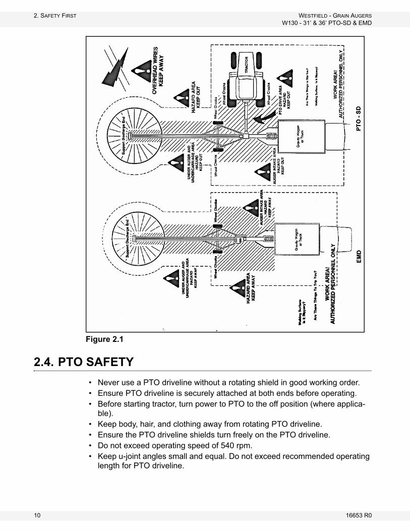
Figure 2.1
2.4. PTO SAFETY
• Never use a PTO driveline without a rotating shield in good working order.• Ensure PTO driveline is securely attached at both ends before operating.• Before starting tractor, turn power to PTO to the off position (where applica-
ble).• Keep body, hair, and clothing away from rotating PTO driveline.• Ensure the PTO driveline shields turn freely on the PTO driveline.• Do not exceed operating speed of 540 rpm.• Keep u-joint angles small and equal. Do not exceed recommended operating
length for PTO driveline.
10 16653 R0
WESTFIELD - GRAIN AUGERS 2. SAFETY FIRST
W130 - 31’ & 36’ PTO-SD & EMD
2.5. ELECTRIC MOTOR SAFETY
• Inspect the drive belts before using auger. Replace if frayed or damaged.• Do not grab or touch drive belts during operation for any reason.• Remember to ground electric motor before using auger.
2.6. TRANSPORT & PLACEMENT SAFETY
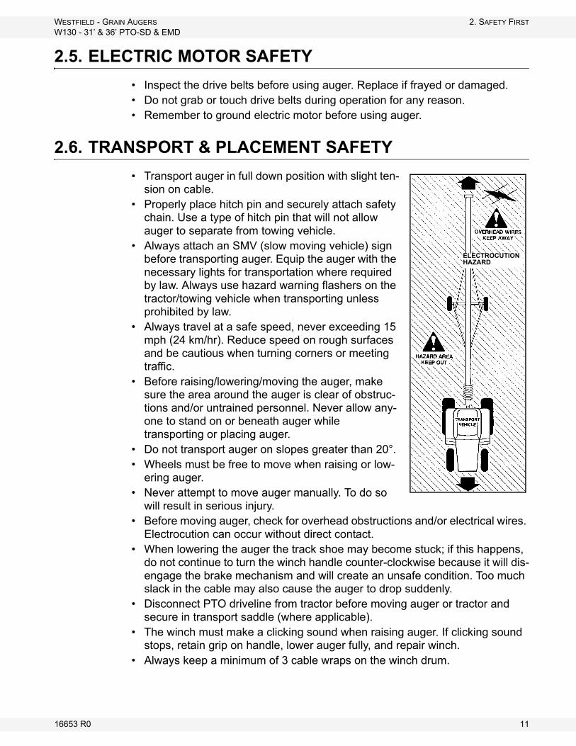
• Transport auger in full down position with slight ten-sion on cable.
• Properly place hitch pin and securely attach safety chain. Use a type of hitch pin that will not allow auger to separate from towing vehicle.
• Always attach an SMV (slow moving vehicle) sign before transporting auger. Equip the auger with the necessary lights for transportation where required by law. Always use hazard warning flashers on the tractor/towing vehicle when transporting unless prohibited by law.
• Always travel at a safe speed, never exceeding 15 mph (24 km/hr). Reduce speed on rough surfaces and be cautious when turning corners or meeting traffic.
• Before raising/lowering/moving the auger, make sure the area around the auger is clear of obstruc-tions and/or untrained personnel. Never allow any-one to stand on or beneath auger while transporting or placing auger.
• Do not transport auger on slopes greater than 20°.• Wheels must be free to move when raising or low-
ering auger.• Never attempt to move auger manually. To do so
will result in serious injury. • Before moving auger, check for overhead obstructions and/or electrical wires.
Electrocution can occur without direct contact.• When lowering the auger the track shoe may become stuck; if this happens,
do not continue to turn the winch handle counter-clockwise because it will dis-engage the brake mechanism and will create an unsafe condition. Too much slack in the cable may also cause the auger to drop suddenly.
• Disconnect PTO driveline from tractor before moving auger or tractor and secure in transport saddle (where applicable).
• The winch must make a clicking sound when raising auger. If clicking sound stops, retain grip on handle, lower auger fully, and repair winch.
• Always keep a minimum of 3 cable wraps on the winch drum.
ELECTROCUTION HAZARD
16653 R0 11
2. SAFETY FIRST WESTFIELD - GRAIN AUGERS
W130 - 31’ & 36’ PTO-SD & EMD
2.7. MAINTENANCE SAFETY
• Shut down and lock out all power before attempting maintenance of any kind. If applicable, disconnect PTO driveline from tractor or hydraulic hoses on units with hydraulic drive hoppers.
• After maintenance is complete, replace and secure all safety guards and safety devices, and if applicable, service doors and cleanout covers.
• Support auger tube before attempting maintenance on the undercarriage assembly. Auger should be in full down position for maintenance.
• Use only genuine Westfield replacement parts or equivalent. Replacement parts such as intake guards, pulley guards, PTO driveline shields, winches, and lift cables must meet ASABE standards or serious injury may result. Use of unauthorized parts will void warranty. If in doubt, contact Westfield or your Westfield dealer.
• Do not modify any auger components without authorization from Westfield. Modification can be dangerous and result in serious injuries.
2.8. SAFETY DECAL LOCATIONS
• Keep safety decals clean and legible at all times.• Replace safety decals that are missing or have become illegible. See decal
location figures that follow.• Replaced parts must display the same decal(s) as the original part.• Safety decals are available from your distributor, dealer, or factory.
2.8.1. DECAL INSTALLATION/REPLACEMENT
1. Decal area must be clean and dry, with a temperature above 50°F (10°C). Use a solvent to remove all traces of oil from manufacturing before applying decal.
2. Decide on the exact position before you remove the backing paper.3. Align the decal over the specified area and carefully press the small portion
with the exposed sticky backing in place.4. Slowly peel back the remaining paper and carefully smooth the remaining
portion of the decal in place.5. Small air pockets can be pierced with a pin and smoothed out using the sign
backing paper.
2.8.2. DECAL LOCATIONS
Replicas of the safety decals that are attached to the equipment are shown in the figure(s) that follow. Proper safety procedures require that you familiarize yourself with the various safety decals and the areas or particular functions that the decals apply to as well as the safety precautions that must be taken to avoid serious injury, death, or equipment damage.
12 16653 R0
WESTFIELD - GRAIN AUGERS 2. SAFETY FIRST
W130 - 31’ & 36’ PTO-SD & EMD
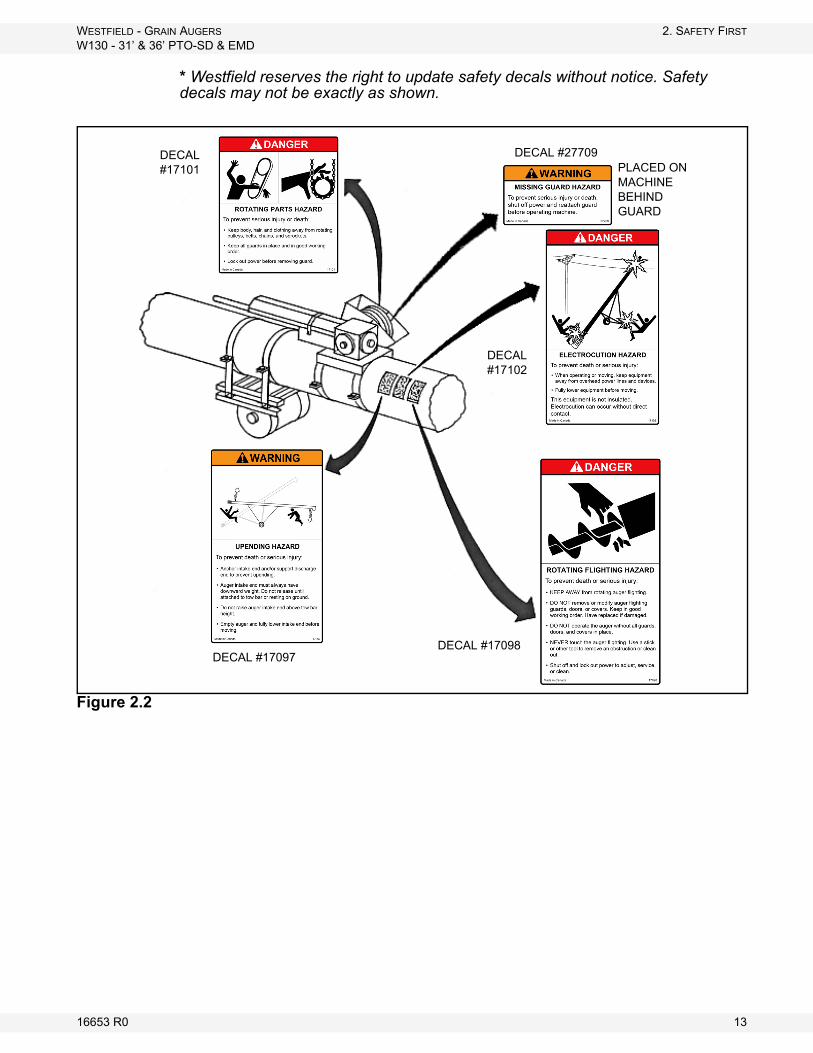
* Westfield reserves the right to update safety decals without notice. Safety decals may not be exactly as shown.
Figure 2.2
DECAL #17101
DECAL #17102
DECAL #17098DECAL #17097
PLACED ON MACHINE BEHIND GUARD
DECAL #27709
16653 R0 13

2. SAFETY FIRST WESTFIELD - GRAIN AUGERS
W130 - 31’ & 36’ PTO-SD & EMD
Figure 2.3
DECAL #17096
DECAL #17109
DECAL #19960
DECAL #17103
DECAL 17113
14 16653 R0
WESTFIELD - GRAIN AUGERS 3. ASSEMBLY
W130 - 31’ & 36’ PTO-SD & EMD
3. Assembly
3.1. PRE-ASSEMBLY
Before beginning assembly, familiarize yourself with all the sub-assemblies and hardware making up the auger. Have all parts on hand and arrange them for easy access. Carry out assembly in a large open area with a level surface.
Important: Always have 2 or more people assembling the equipment. Because of the weight, do not attempt assembly alone.
Augers are available in various combinations. In most cases, the following instructions will apply to all augers. Where the assembly information varies, additional instructions will be included and will be indicated with an arrow.
3.2. TUBES & FLIGHTING
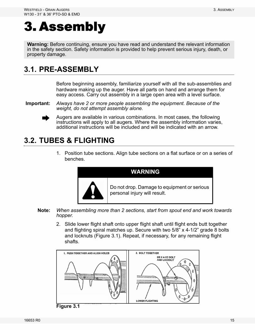
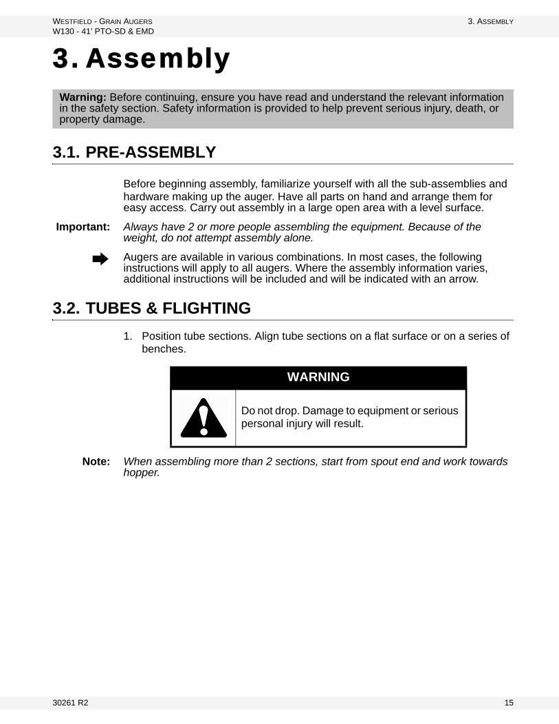
1. Position tube sections. Align tube sections on a flat surface or on a series of benches.
Note: When assembling more than 2 sections, start from spout end and work towards hopper.
2. Slide lower flight shaft onto upper flight shaft until flight ends butt together and flighting spiral matches up. Secure with two 5/8” x 4-1/2” grade 8 bolts and locknuts (Figure 3.1). Repeat, if necessary, for any remaining flight shafts.
Figure 3.1
Warning: Before continuing, ensure you have read and understand the relevant information in the safety section. Safety information is provided to help prevent serious injury, death, or property damage.
WARNING
Do not drop. Damage to equipment or serious personal injury will result.
16653 R0 15
3. ASSEMBLY WESTFIELD - GRAIN AUGERS
W130 - 31’ & 36’ PTO-SD & EMD
3.3. TRACK SHOE & TRACKSTOP
1. Slide the roller track shoe onto track.
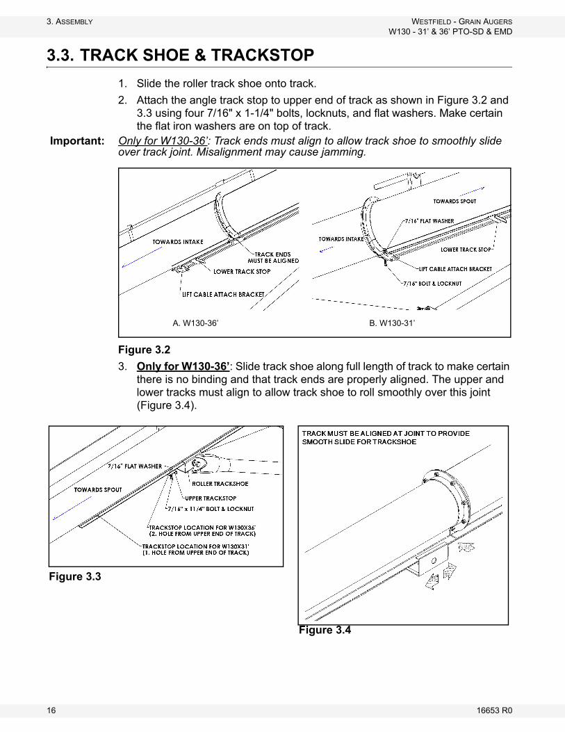
2. Attach the angle track stop to upper end of track as shown in Figure 3.2 and 3.3 using four 7/16" x 1-1/4" bolts, locknuts, and flat washers. Make certain the flat iron washers are on top of track.
Important: Only for W130-36’: Track ends must align to allow track shoe to smoothly slide over track joint. Misalignment may cause jamming.
Figure 3.2
3. Only for W130-36’: Slide track shoe along full length of track to make certain there is no binding and that track ends are properly aligned. The upper and lower tracks must align to allow track shoe to roll smoothly over this joint (Figure 3.4).
A. W130-36’ B. W130-31’
Figure 3.4
Figure 3.3
16 16653 R0
WESTFIELD - GRAIN AUGERS 3. ASSEMBLY
W130 - 31’ & 36’ PTO-SD & EMD
3.4. INTAKE HITCH
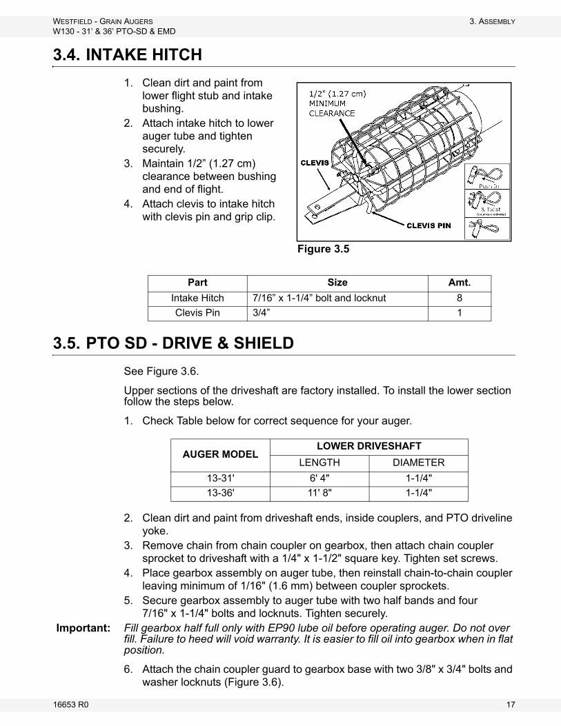
1. Clean dirt and paint from lower flight stub and intake bushing.
2. Attach intake hitch to lower auger tube and tighten securely.
3. Maintain 1/2” (1.27 cm) clearance between bushing and end of flight.
4. Attach clevis to intake hitch with clevis pin and grip clip.
3.5. PTO SD - DRIVE & SHIELD
See Figure 3.6.
Upper sections of the driveshaft are factory installed. To install the lower section follow the steps below.
1. Check Table below for correct sequence for your auger.
2. Clean dirt and paint from driveshaft ends, inside couplers, and PTO driveline yoke.
3. Remove chain from chain coupler on gearbox, then attach chain coupler sprocket to driveshaft with a 1/4" x 1-1/2" square key. Tighten set screws.
4. Place gearbox assembly on auger tube, then reinstall chain-to-chain coupler leaving minimum of 1/16" (1.6 mm) between coupler sprockets.
5. Secure gearbox assembly to auger tube with two half bands and four 7/16" x 1-1/4" bolts and locknuts. Tighten securely.
Important: Fill gearbox half full only with EP90 lube oil before operating auger. Do not over fill. Failure to heed will void warranty. It is easier to fill oil into gearbox when in flat position.
6. Attach the chain coupler guard to gearbox base with two 3/8" x 3/4" bolts and washer locknuts (Figure 3.6).
Part Size Amt.
Intake Hitch 7/16” x 1-1/4” bolt and locknut 8
Clevis Pin 3/4” 1
Figure 3.5
AUGER MODELLOWER DRIVESHAFT
LENGTH DIAMETER
13-31' 6' 4" 1-1/4"
13-36' 11' 8" 1-1/4"
16653 R0 17
3. ASSEMBLY WESTFIELD - GRAIN AUGERS
W130 - 31’ & 36’ PTO-SD & EMD
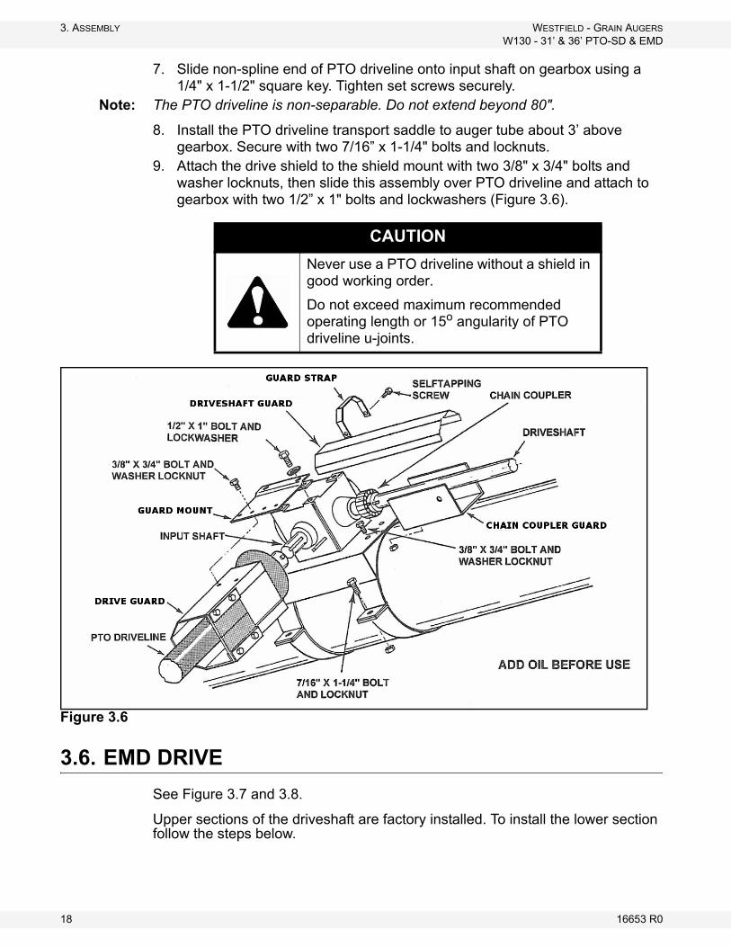
7. Slide non-spline end of PTO driveline onto input shaft on gearbox using a 1/4" x 1-1/2" square key. Tighten set screws securely.
Note: The PTO driveline is non-separable. Do not extend beyond 80".
8. Install the PTO driveline transport saddle to auger tube about 3’ above gearbox. Secure with two 7/16” x 1-1/4" bolts and locknuts.
9. Attach the drive shield to the shield mount with two 3/8" x 3/4" bolts and washer locknuts, then slide this assembly over PTO driveline and attach to gearbox with two 1/2” x 1" bolts and lockwashers (Figure 3.6).
Figure 3.6
3.6. EMD DRIVE
See Figure 3.7 and 3.8.
Upper sections of the driveshaft are factory installed. To install the lower section follow the steps below.
CAUTION
Never use a PTO driveline without a shield in good working order.
Do not exceed maximum recommended operating length or 15o angularity of PTO driveline u-joints.
18 16653 R0
WESTFIELD - GRAIN AUGERS 3. ASSEMBLY
W130 - 31’ & 36’ PTO-SD & EMD
1. Check Table below for correct sequence for your auger.
2. Clean dirt and paint from driveshaft ends and inside couplers.3. Remove chain from chain coupler on gearbox, then attach chain coupler
sprocket to driveshaft with a 1/4" x 1-1/2" square key. Tighten set screw.4. Place gearbox assembly on auger tube, then reinstall chain coupler leaving
minimum of 1/16" between coupler sprockets.5. Secure gearbox assembly to auger tube with two half bands and four
7/16" x 1-1/4" bolts and locknuts. Tighten securely.6. Attach the chain coupler guard to gearbox base with two 3/8" x 3/4" bolts and
washer locknuts.Important: Ensure that gearbox is half full with EP90 lube oil before operating auger. Do not
overfill. Failure to heed will void warranty. It is easier to fill oil into the gearbox when it is in the horizontal position.
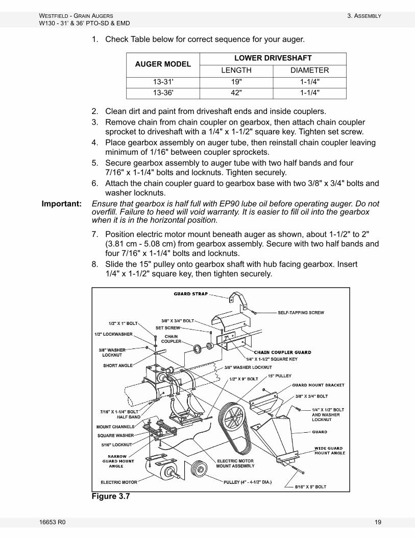
7. Position electric motor mount beneath auger as shown, about 1-1/2" to 2" (3.81 cm - 5.08 cm) from gearbox assembly. Secure with two half bands and four 7/16" x 1-1/4" bolts and locknuts.
8. Slide the 15" pulley onto gearbox shaft with hub facing gearbox. Insert 1/4" x 1-1/2" square key, then tighten securely.
Figure 3.7
AUGER MODELLOWER DRIVESHAFT
LENGTH DIAMETER
13-31' 19" 1-1/4"
13-36' 42" 1-1/4"
16653 R0 19

3. ASSEMBLY WESTFIELD - GRAIN AUGERS
W130 - 31’ & 36’ PTO-SD & EMD
STEPS 9. THROUGH 16. MAY BE COMPLETED AT THIS TIME OR AFTER AUGER TUBE AND UNDERCARRIAGE ASSEMBLY IS COMPLETED.
9. Place drive pulley onto motor shaft, then insert square key and tighten set screws. (A 4" to 4-1/2" pulley is recommended. Pulley and square key are not supplied).
10. Attach electric motor to motor mount with four bolts and locknuts (not provided) and four square washers (provided). The square washers go inside the mount channels.
11. Attach the “narrow” guard mount angle to the motor mount channels with two 7/16" x 1-1/4" bolts, square washers, and locknuts. Align angle with outside edge of the mount channels.
12. Place belts on the pulleys and apply slight tension. Align the two pulleys with a straight edge, then tighten set screws.
13. Apply final tension to belts with the 1/2” x 9" adjusting bolts on the motor mount.
Note: The correct operating tension is the lowest tension at which the belts will not slip under peak load conditions.
14. Place the short angle on top of the gearbox as shown and attach with two 1/2” x 1" bolts and lockwashers.
Figure 3.8
15. Attach the guard to gearbox assembly by bolting the guard mount bracket to the short angle with one 3/8" x 3/4" bolt and washer locknut.
16. Secure the other end of guard by bolting the “wide” guard mount angle to the “narrow” guard mount angle with two 5/16" x 5" bolts and locknuts. Adjust the width of guard at the motor pulley to suit the pulley diameter.
20 16653 R0

WESTFIELD - GRAIN AUGERS 3. ASSEMBLY
W130 - 31’ & 36’ PTO-SD & EMD
3.7. DRIVESHAFT SHIELD
Before installing the driveshaft shields, refer to Table 3.1 for the proper sequence for your particular auger. Install shields working from the gearbox assembly up to the discharge end.
To install:
1. Place driveshaft shield against gearbox and over chain coupler guard, then secure with a guard strap and 2 self-tapping screws (Figure 3.6).
2. To install remainder of the driveshaft shielding, work from the bottom up. Shields should overlap at bearing support brackets (Figure 3.9).
Note: When installing driveshaft shielding, refer to step 1 in Table 3.1.
3. Fasten with shield strap and self-tapping screws. Do not tighten until all shielding is in place.
When using an electric motor:
• The motor and controls should be installed by a qualified electrician in accordance with all local and national codes.
• Incorporate a magnetic starter to protect the motor.• The motor must have a manual reset button.• Locate reset and starter controls so that the operator has full view of the
entire operation.• Locate main power disconnect switch within reach from ground level to
permit ready access in case of an emergency.• A main power disconnect switch capable of being locked (in the off posi-
tion only) must be provided.
Figure 3.9
Table 3.1 Driveshaft Shielding Sequence
STEP130-31 SD 130-31 EMD
QTY LENGTH QTY LENGTH
1 1 42" (1.07 m) 1 42" (1.07 m)
2 6 48" (1.22 m) 4 48" (1.22 m)
3 - 42" (1.07 m) 1 42" (1.07 m)
STEP130-36 SD 130-36 EMD
QTY LENGTH QTY LENGTH
1 1 42" (1.07 m) 1 42" (1.07 m)
2 6 48" (1.22 m) 4 48" (1.22 m)
3 1 60" (1.52 m) 1 60" (1.52 m)
16653 R0 21
3. ASSEMBLY WESTFIELD - GRAIN AUGERS
W130 - 31’ & 36’ PTO-SD & EMD
3.8. DISCHARGE SPOUT
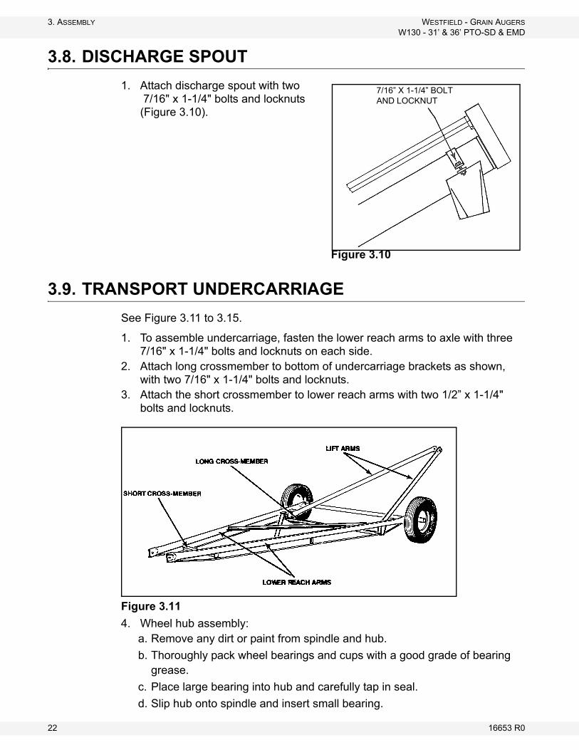
1. Attach discharge spout with two 7/16" x 1-1/4" bolts and locknuts (Figure 3.10).
3.9. TRANSPORT UNDERCARRIAGE
See Figure 3.11 to 3.15.
1. To assemble undercarriage, fasten the lower reach arms to axle with three 7/16" x 1-1/4" bolts and locknuts on each side.
2. Attach long crossmember to bottom of undercarriage brackets as shown, with two 7/16" x 1-1/4" bolts and locknuts.
3. Attach the short crossmember to lower reach arms with two 1/2” x 1-1/4" bolts and locknuts.
Figure 3.11
4. Wheel hub assembly:a. Remove any dirt or paint from spindle and hub.
b. Thoroughly pack wheel bearings and cups with a good grade of bearing grease.
c. Place large bearing into hub and carefully tap in seal.
d. Slip hub onto spindle and insert small bearing.
Figure 3.10
7/16” X 1-1/4” BOLTAND LOCKNUT
22 16653 R0
WESTFIELD - GRAIN AUGERS 3. ASSEMBLY
W130 - 31’ & 36’ PTO-SD & EMD
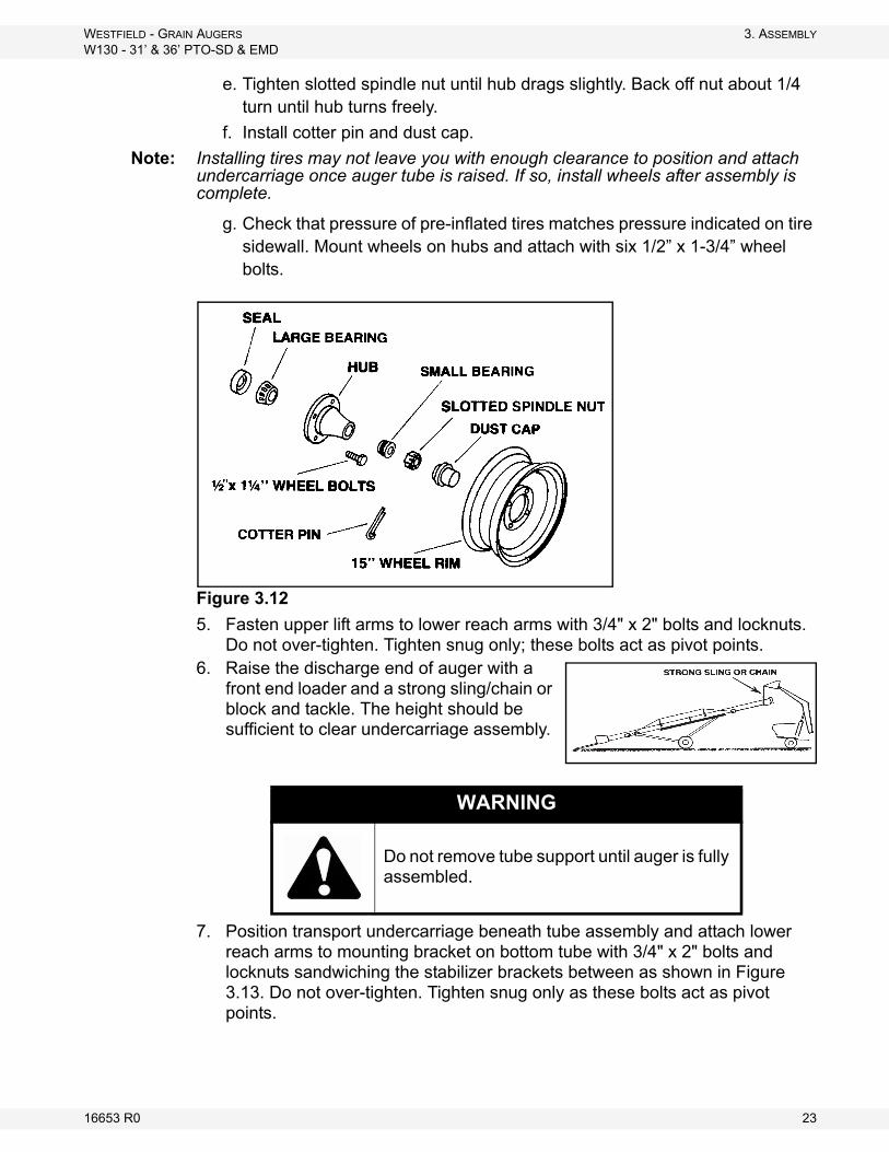
e. Tighten slotted spindle nut until hub drags slightly. Back off nut about 1/4 turn until hub turns freely.
f. Install cotter pin and dust cap.
Note: Installing tires may not leave you with enough clearance to position and attach undercarriage once auger tube is raised. If so, install wheels after assembly is complete.
g. Check that pressure of pre-inflated tires matches pressure indicated on tire sidewall. Mount wheels on hubs and attach with six 1/2” x 1-3/4” wheel bolts.
Figure 3.12
5. Fasten upper lift arms to lower reach arms with 3/4" x 2" bolts and locknuts. Do not over-tighten. Tighten snug only; these bolts act as pivot points.
6. Raise the discharge end of auger with a front end loader and a strong sling/chain or block and tackle. The height should be sufficient to clear undercarriage assembly.
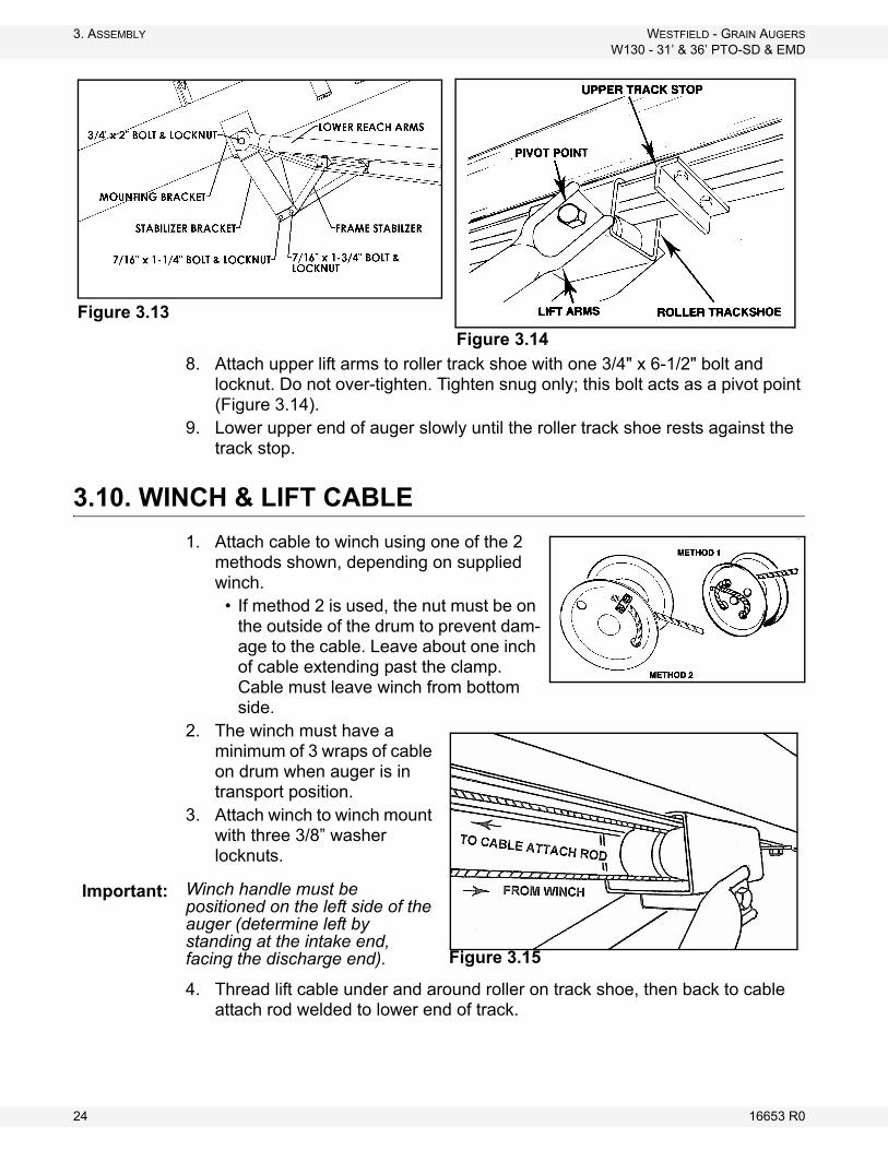
7. Position transport undercarriage beneath tube assembly and attach lower reach arms to mounting bracket on bottom tube with 3/4" x 2" bolts and locknuts sandwiching the stabilizer brackets between as shown in Figure 3.13. Do not over-tighten. Tighten snug only as these bolts act as pivot points.
WARNING
Do not remove tube support until auger is fully assembled.
16653 R0 23
3. ASSEMBLY WESTFIELD - GRAIN AUGERS
W130 - 31’ & 36’ PTO-SD & EMD
8. Attach upper lift arms to roller track shoe with one 3/4" x 6-1/2" bolt and locknut. Do not over-tighten. Tighten snug only; this bolt acts as a pivot point (Figure 3.14).
9. Lower upper end of auger slowly until the roller track shoe rests against the track stop.
3.10. WINCH & LIFT CABLE
1. Attach cable to winch using one of the 2 methods shown, depending on supplied winch.
• If method 2 is used, the nut must be on the outside of the drum to prevent dam-age to the cable. Leave about one inch of cable extending past the clamp. Cable must leave winch from bottom side.
2. The winch must have a minimum of 3 wraps of cable on drum when auger is in transport position.
3. Attach winch to winch mount with three 3/8” washer locknuts.
Winch handle must be positioned on the left side of the auger (determine left by standing at the intake end, facing the discharge end).
4. Thread lift cable under and around roller on track shoe, then back to cable attach rod welded to lower end of track.
Figure 3.14
Figure 3.13
Figure 3.15
Important:
24 16653 R0
WESTFIELD - GRAIN AUGERS 3. ASSEMBLY
W130 - 31’ & 36’ PTO-SD & EMD
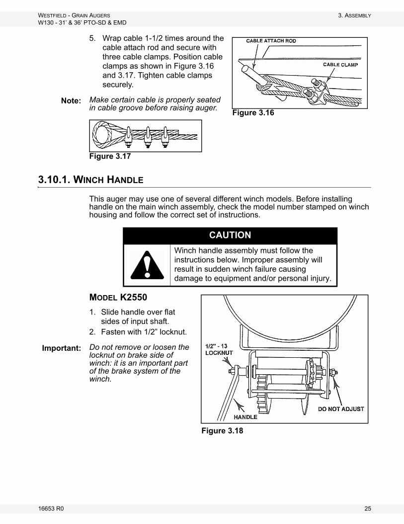
5. Wrap cable 1-1/2 times around the cable attach rod and secure with three cable clamps. Position cable clamps as shown in Figure 3.16 and 3.17. Tighten cable clamps securely.
Make certain cable is properly seated in cable groove before raising auger.
Figure 3.17
3.10.1. WINCH HANDLE
This auger may use one of several different winch models. Before installing handle on the main winch assembly, check the model number stamped on winch housing and follow the correct set of instructions.
MODEL K2550
1. Slide handle over flat sides of input shaft.
2. Fasten with 1/2” locknut.
Do not remove or loosen the locknut on brake side of winch: it is an important part of the brake system of the winch.
Figure 3.16
Note:
CAUTION
Winch handle assembly must follow the instructions below. Improper assembly will result in sudden winch failure causing damage to equipment and/or personal injury.
Figure 3.18
Important:
16653 R0 25
3. ASSEMBLY WESTFIELD - GRAIN AUGERS
W130 - 31’ & 36’ PTO-SD & EMD
3.11. UPPER HOUSING LUBRICATION
Fill enclosed upper drive housing with grease.
For continuous use in extreme cold conditions, semi-fluid arctic grease or heavy oil may be used.
3.12. PLASTIC MANUAL HOLDER
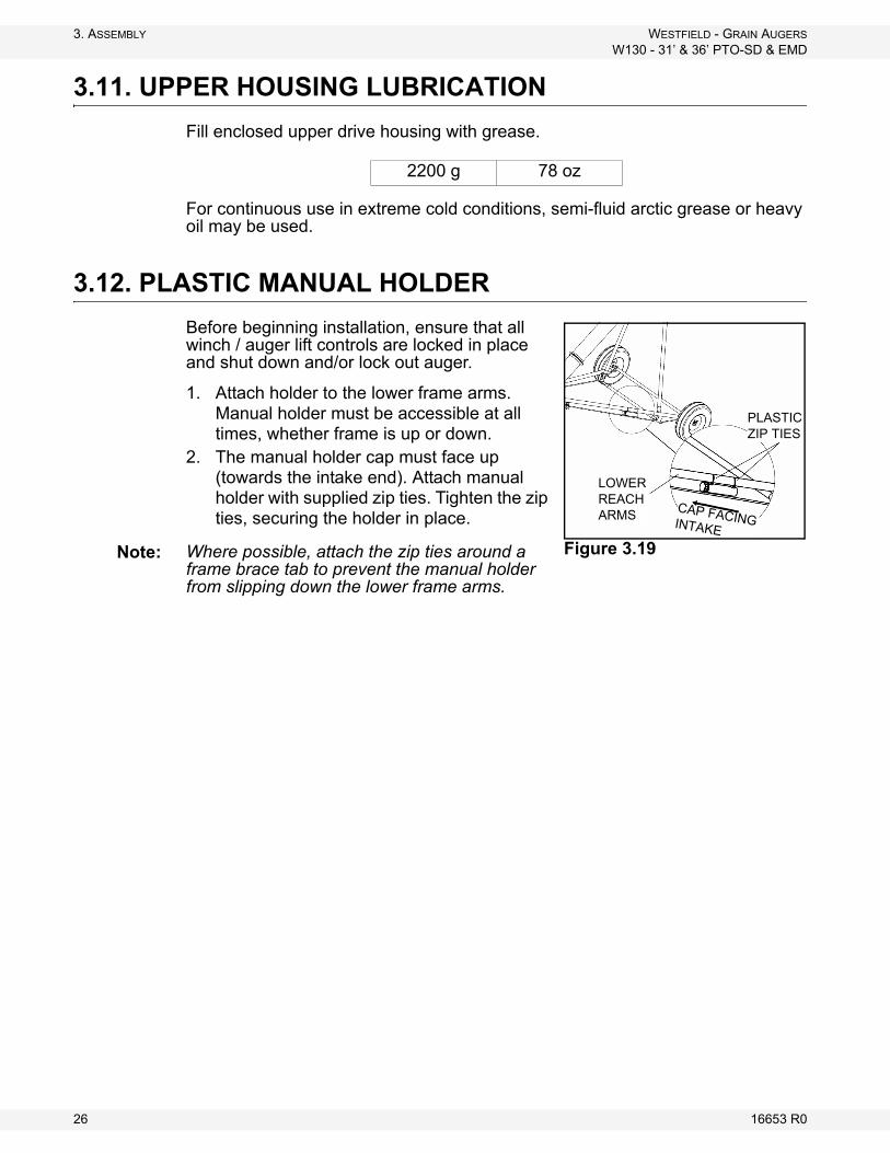
Before beginning installation, ensure that all winch / auger lift controls are locked in place and shut down and/or lock out auger.
1. Attach holder to the lower frame arms. Manual holder must be accessible at all times, whether frame is up or down.
2. The manual holder cap must face up (towards the intake end). Attach manual holder with supplied zip ties. Tighten the zip ties, securing the holder in place.
Where possible, attach the zip ties around a frame brace tab to prevent the manual holder from slipping down the lower frame arms.
2200 g 78 oz
LOWER REACH ARMS
PLASTIC ZIP TIES
CAP FACING INTAKE
Figure 3.19 Note:
26 16653 R0
WESTFIELD - GRAIN AUGERS 3. ASSEMBLY
W130 - 31’ & 36’ PTO-SD & EMD
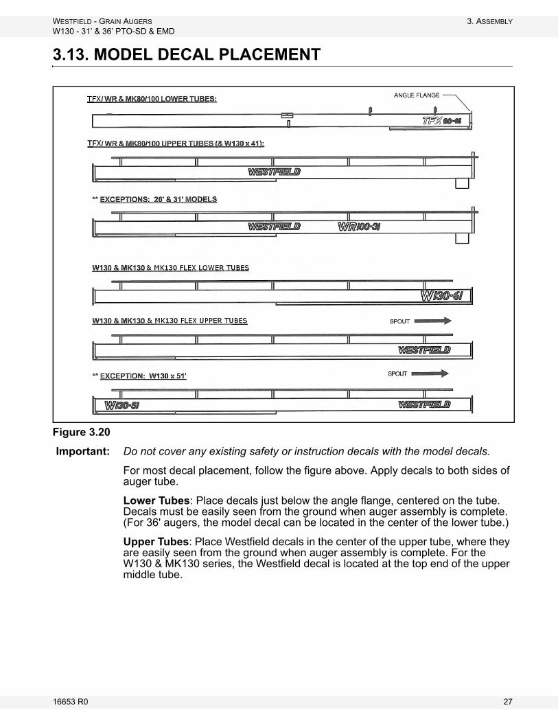
3.13. MODEL DECAL PLACEMENT
Figure 3.20
Important: Do not cover any existing safety or instruction decals with the model decals.
For most decal placement, follow the figure above. Apply decals to both sides of auger tube.
Lower Tubes: Place decals just below the angle flange, centered on the tube. Decals must be easily seen from the ground when auger assembly is complete. (For 36' augers, the model decal can be located in the center of the lower tube.)
Upper Tubes: Place Westfield decals in the center of the upper tube, where they are easily seen from the ground when auger assembly is complete. For the W130 & MK130 series, the Westfield decal is located at the top end of the upper middle tube.
16653 R0 27

3. ASSEMBLY WESTFIELD - GRAIN AUGERS
W130 - 31’ & 36’ PTO-SD & EMD
28 16653 R0
WESTFIELD - GRAIN AUGERS 4. TRANSPORT & PLACEMENT
W130 - 31’ & 36’ PTO-SD & EMD
4. Transport & Placement
4.1. TRANSPORT PROCEDURE
Follow all safety precautions when transporting the auger and use a proper towing vehicle.
1. If auger is raised, place in full down position. The roller track shoe should be seated against the upper track stop with slight tension on the lift cable. Refer to “Lowering & Completion” on page 37.
2. Lock winch: turn handle clockwise until 2 clicks are heard.Important: The winch must have a minimum of 3 wraps of cable on drum when auger is in
transport position.
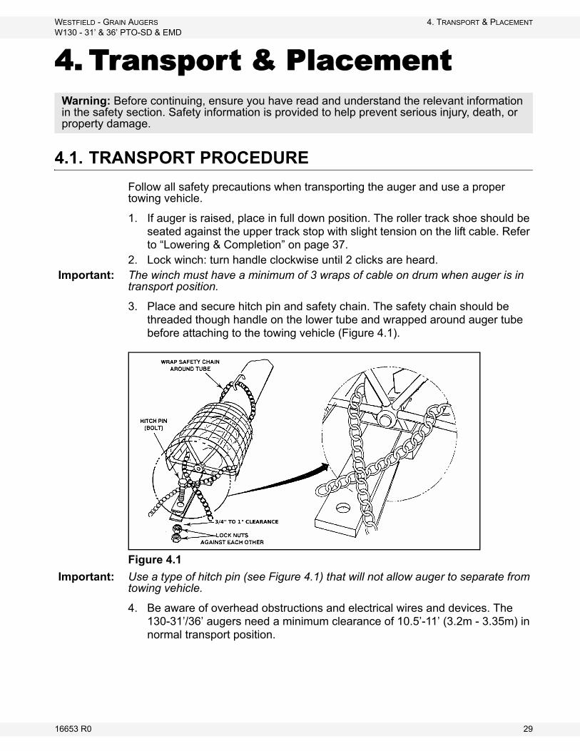
3. Place and secure hitch pin and safety chain. The safety chain should be threaded though handle on the lower tube and wrapped around auger tube before attaching to the towing vehicle (Figure 4.1).
Figure 4.1
Important: Use a type of hitch pin (see Figure 4.1) that will not allow auger to separate from towing vehicle.
4. Be aware of overhead obstructions and electrical wires and devices. The 130-31’/36’ augers need a minimum clearance of 10.5’-11’ (3.2m - 3.35m) in normal transport position.
Warning: Before continuing, ensure you have read and understand the relevant information in the safety section. Safety information is provided to help prevent serious injury, death, or property damage.
16653 R0 29
4. TRANSPORT & PLACEMENT WESTFIELD - GRAIN AUGERS
W130 - 31’ & 36’ PTO-SD & EMD
5. Refer to “Transport & Placement Safety” on page 11 for important safety information before towing.
4.2. PLACEMENT PROCEDURE
1. Ensure towing hitch is in place and secure.Important: Use a type of hitch pin (Figure 4.1) that will not allow auger to separate from
towing vehicle.
2. Before raising or positioning auger, make sure that entire area in line of travel, both on the ground and overhead, is clear of any obstructions or electrical wires.
3. Ensure auger is on reasonably level ground when raising, lowering, or positioning.
Note: Make certain cable is properly seated in cable groove before raising auger. Refer to Figure 3.25.
4. To raise auger, turn winch handle clockwise. Use a firm grip on winch handle; do not release unless the ratchet pawl is fully engaged.
Important: Winch must make clicking sound when raising auger. If clicking stops, retain grip on handle, lower auger fully, and repair ratchet.
Note: Do not turn winch handle counter-clockwise except when lowering auger or severe damage to winch will occur.
CAUTION
If auger wheels are partially or fully buried in snow or grain, failure to clear area around the wheels before moving may cause damage to the auger or result in serious injury.
WARNING
If auger wheels are partially or fully buried in snow or grain, failure to clear the area around the wheels before moving may cause damage to the auger or result in serious injury.
NOTICE
Do not turn winch handle counter-clockwise except when lowering auger or severe damage to winch will occur.
30 16653 R0
WESTFIELD - GRAIN AUGERS 4. TRANSPORT & PLACEMENT
W130 - 31’ & 36’ PTO-SD & EMD
PTO Models Only: The driveline is non-separable. Remove from tractor and secure in transport saddle on auger before moving tractor away from auger.
5. Move the auger into working position slowly. Do not unhitch and attempt to move auger by hand.
6. Once auger is in position, chock wheels on both sides and apply the park brake on the tractor (or chock its wheels as well) to prevent movement during operation.
Important: When releasing auger from the towing vehicle, test the intake end for downward weight. Do not raise the intake end above drawbar height. When the intake end is elevated too high with auger in raised position, the balance of weight quickly transfers to the discharge end, causing it to upend. Ensure proper anchoring/support.
7. When operating auger in the raised position, rest the discharge end lightly on the bin roof, or tie to bin to prevent wind from toppling auger. When operating the auger in a freestanding position, anchor the intake end.
8. Anchor and/or support auger during operation.• When lower half of auger empties of grain, the weight balance transfers
to upper end of auger, which can cause upending.9. See “Lowering & Completion” on page 37 for correct lowering procedure.
WARNING
Never attempt to increase height of auger by positioning wheels on lumber, clocks, or by any other means. To do so will result in damage to equipment and/or personal injury.
CAUTION
Do not use auger as a hoist to raise any object regardless of weight. This will create an unsafe condition and will void warranty.
16653 R0 31

4. TRANSPORT & PLACEMENT WESTFIELD - GRAIN AUGERS
W130 - 31’ & 36’ PTO-SD & EMD
32 16653 R0
WESTFIELD - GRAIN AUGERS 5. OPERATION
W130 - 31’ & 36’ PTO-SD & EMD
5. Operation
Operators must observe safety procedures at all times and follow the pre-opera-tional checklist before each start-up.
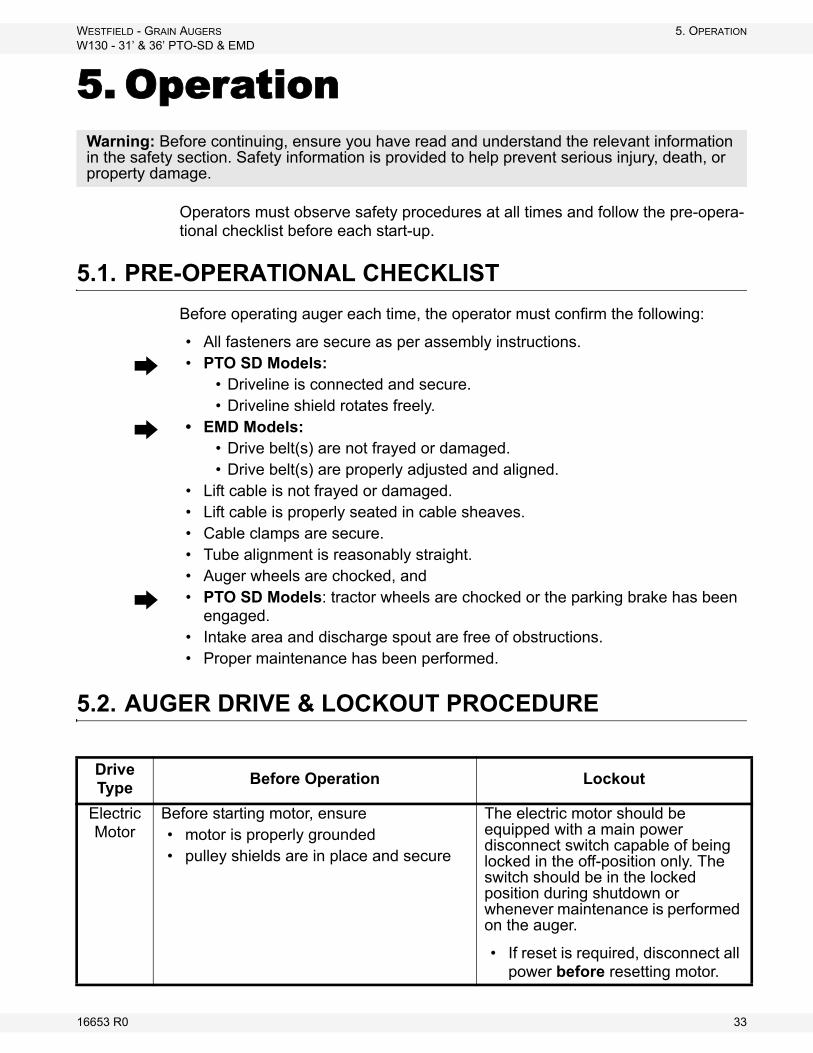
5.1. PRE-OPERATIONAL CHECKLIST
Before operating auger each time, the operator must confirm the following:
• All fasteners are secure as per assembly instructions.
• PTO SD Models: • Driveline is connected and secure.• Driveline shield rotates freely.
• EMD Models: • Drive belt(s) are not frayed or damaged.• Drive belt(s) are properly adjusted and aligned.
• Lift cable is not frayed or damaged.• Lift cable is properly seated in cable sheaves.• Cable clamps are secure.• Tube alignment is reasonably straight.• Auger wheels are chocked, and
• PTO SD Models: tractor wheels are chocked or the parking brake has been engaged.
• Intake area and discharge spout are free of obstructions.• Proper maintenance has been performed.
5.2. AUGER DRIVE & LOCKOUT PROCEDURE
Warning: Before continuing, ensure you have read and understand the relevant information in the safety section. Safety information is provided to help prevent serious injury, death, or property damage.
Drive Type
Before Operation Lockout
Electric Motor
Before starting motor, ensure• motor is properly grounded• pulley shields are in place and secure
The electric motor should be equipped with a main power disconnect switch capable of being locked in the off-position only. The switch should be in the locked position during shutdown or whenever maintenance is performed on the auger.
• If reset is required, disconnect all power before resetting motor.
16653 R0 33
5. OPERATION WESTFIELD - GRAIN AUGERS
W130 - 31’ & 36’ PTO-SD & EMD
5.3. OPERATING PROCEDURE
5.3.1. START-UP & BREAK IN
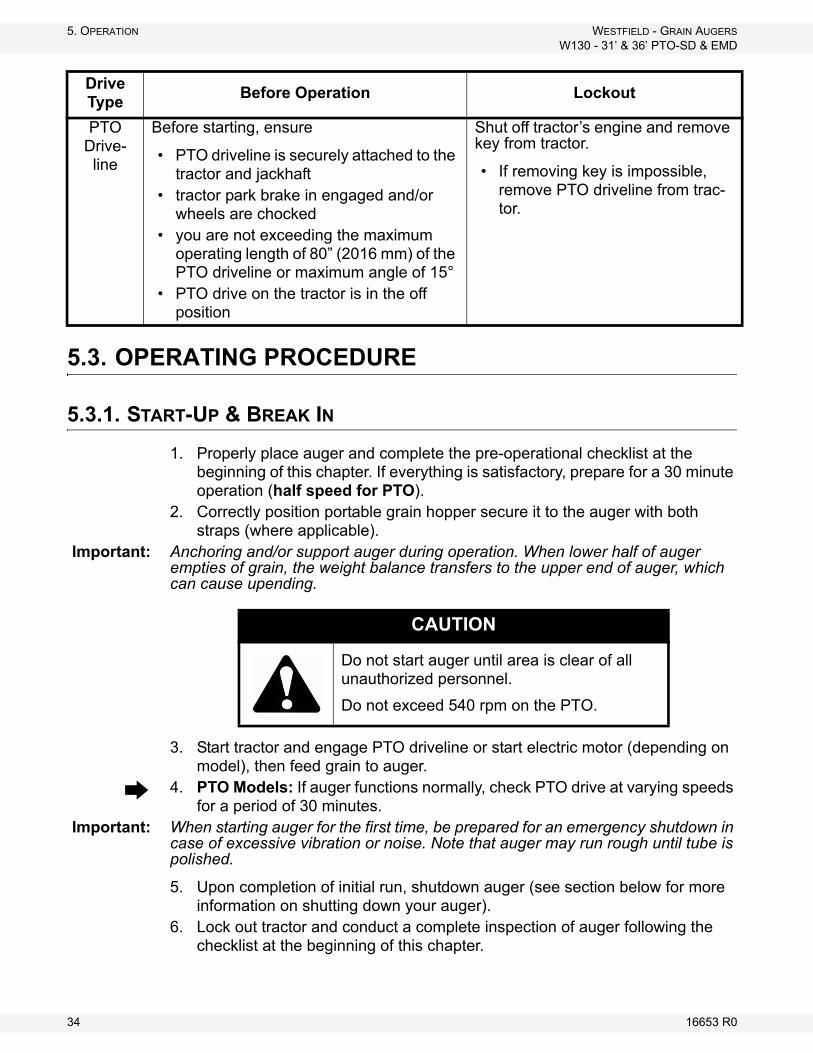
1. Properly place auger and complete the pre-operational checklist at the beginning of this chapter. If everything is satisfactory, prepare for a 30 minute operation (half speed for PTO).
2. Correctly position portable grain hopper secure it to the auger with both straps (where applicable).
Important: Anchoring and/or support auger during operation. When lower half of auger empties of grain, the weight balance transfers to the upper end of auger, which can cause upending.
3. Start tractor and engage PTO driveline or start electric motor (depending on model), then feed grain to auger.
4. PTO Models: If auger functions normally, check PTO drive at varying speeds for a period of 30 minutes.
Important: When starting auger for the first time, be prepared for an emergency shutdown in case of excessive vibration or noise. Note that auger may run rough until tube is polished.
5. Upon completion of initial run, shutdown auger (see section below for more information on shutting down your auger).
6. Lock out tractor and conduct a complete inspection of auger following the checklist at the beginning of this chapter.
PTO Drive-line
Before starting, ensure
• PTO driveline is securely attached to the tractor and jackhaft
• tractor park brake in engaged and/or wheels are chocked
• you are not exceeding the maximum operating length of 80” (2016 mm) of the PTO driveline or maximum angle of 15°
• PTO drive on the tractor is in the off position
Shut off tractor’s engine and remove key from tractor.
• If removing key is impossible, remove PTO driveline from trac-tor.
Drive Type
Before Operation Lockout
CAUTION
Do not start auger until area is clear of all unauthorized personnel.
Do not exceed 540 rpm on the PTO.
34 16653 R0

WESTFIELD - GRAIN AUGERS 5. OPERATION
W130 - 31’ & 36’ PTO-SD & EMD
After the initial start-up and inspection, the auger should be shut down and inspected at least three more times during the first 10 hours of operation.
Keep operation of empty auger to a minimum, as this results in excessive wear.
Once auger is broken in, the checklist should be a part of the daily routine before operating auger.
5.3.2. OPERATING WITH A FULL LOAD
1. When operating the auger, always work with a second person in a position to monitor the operation and initiate a shutdown in case of emergency.
2. Monitor the auger during operation for abnormal noises or vibrations.3. Shut off all power before making adjustments, servicing, or clearing the
machine.
DANGER
Rotating Flighting Hazard!
To prevent death or serious injury:• Keep away from rotating auger flighting.• Do not remove or modify auger flighting
guards, doors, or covers. Keep in good working order. Have replaced if damaged.
• Do not operate the auger without all guards, doors, and covers in place.
• Never touch the auger flighting. Use a stick or other tool to remove an obstruc-tion or clean out.
• Shut off and lock out power to adjust, service, or clean.
USE OF GRAIN SPREADERS: Many grain spreaders cannot handle the large capacity of some augers. Some augers plug, causing damage to the flighting and other drive components. This type of damage is not covered by warranty. Hints on how to avoid this...
• Get a larger spreader, if available.• Remove the spreader.• Make sure spreader is turned on.• Center auger spout on spreader.• Do not lower auger spout into spreader.• Suspend the spreader from bin ceiling leaving extra room for excess
grain to flow over the spreader.
BIN LEVEL INDICATORS: These augers are fast and bins fill up quickly. A full bin will cause auger to plug, which can damage the flighting and other drive components. Installing quality grain-level indicators on your bins will allow you to monitor bin filling and help prevent damage to your auger.
16653 R0 35

5. OPERATION WESTFIELD - GRAIN AUGERS
W130 - 31’ & 36’ PTO-SD & EMD
5.3.3. SHUTDOWN
PTO
NORMAL SHUTDOWN:
1. Near the end of a load, decrease auger speed until all grain is clear of machine.
2. When auger is clear of grain, disengage PTO drive.3. Shut down and lock out tractor.
EMERGENCY / FULL-TUBE RESTART:
1. If the auger is shut down for an emergency, lock out tractor before correcting the problem.
• If the problem is plugging, clear as much of the grain as possible using a piece of wood, wet/dry vac, or other tool before restarting auger. Do not reach in and use your hands even if the tractor has been locked out.
2. If auger tube is full of grain, do not restart at full speed. Engage PTO at low rpm, gradually increasing power until normal operating speed is reached.
EMD
NORMAL SHUTDOWN:
1. Near the end of a load, decrease the flow of grain until auger is clear.2. Once auger is clear, stop motor and lock out power.
Note: The flighting rpm on augers equipped with electric motors is not adjustable. To clear auger of grain, decrease the grain flow until auger is clear and stop motor.
EMERGENCY / FULL-TUBE RESTART:
1. If the auger is shut down for an emergency, lock out motor before correcting the problem.
• If the problem is plugging, clear as much of the grain as possible using a piece of wood, shop vac, or other tool before restarting auger. Do not reach in and use your hands (See “Auger Drive & Lockout Procedure” on page 33.” for lockout procedure.)
NOTICE
Starting the auger when there is grain blockage will result in damage.
NOTICE
Starting the auger under load may result in damage to unit. Be sure there is no blockage.
36 16653 R0

WESTFIELD - GRAIN AUGERS 5. OPERATION
W130 - 31’ & 36’ PTO-SD & EMD
5.3.4. LOWERING & COMPLETION
After operation:
1. Clean entire work area.2. Remove all supports and chocks.3. Move auger out of working position and lower fully (see shaded box that
follows for lowering procedure).4. Move auger to the next work area or to a storage area and then clean out.
5. Clean out auger.a. Shut off tractor engine and lock out power.
b. Manually clean out grain with a piece of wood, vacuum cleaner, or other tool. Do not use hands.
6. Prepare for transport and placement or storage (see appropriate chapters for more information).
LOWERING
1. For PTO drives: disconnect driveline from tractor before lowering.2. Ensure area beneath auger is clear.3. Turn winch counterclockwise to lower (no clicking sound when lowering).4. After lowering, turn handle clockwise until you hear 2 clicks to lock brake.
• Use a firm grip on handle. Do not release unless ratchet pawl is fully engaged.
• The winch is designed for manual operation only.• When lowering, never continue to turn handle counterclockwise if the
cable does not keep moving out under load. This will disengage the brake mechanism and create an unsafe condition. If this happens, winch in slack cable and correct problem.
Do not leave auger in raised position when not in use. Auger could drop rapidly due to a cable break. High winds may also upset auger.
16653 R0 37

5. OPERATION WESTFIELD - GRAIN AUGERS
W130 - 31’ & 36’ PTO-SD & EMD
38 16653 R0
WESTFIELD - GRAIN AUGERS 6. MAINTENANCE & STORAGE
W130 - 31’ & 36’ PTO-SD & EMD
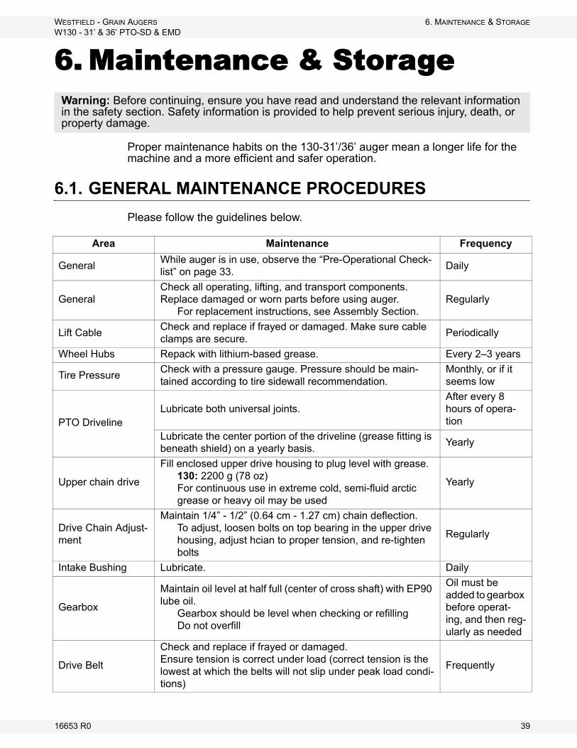
6. Maintenance & Storage
Proper maintenance habits on the 130-31’/36’ auger mean a longer life for the machine and a more efficient and safer operation.
6.1. GENERAL MAINTENANCE PROCEDURES
Please follow the guidelines below.
Warning: Before continuing, ensure you have read and understand the relevant information in the safety section. Safety information is provided to help prevent serious injury, death, or property damage.
Area Maintenance Frequency
GeneralWhile auger is in use, observe the “Pre-Operational Check-list” on page 33.
Daily
GeneralCheck all operating, lifting, and transport components. Replace damaged or worn parts before using auger.
For replacement instructions, see Assembly Section.Regularly
Lift CableCheck and replace if frayed or damaged. Make sure cable clamps are secure.
Periodically
Wheel Hubs Repack with lithium-based grease. Every 2–3 years
Tire PressureCheck with a pressure gauge. Pressure should be main-tained according to tire sidewall recommendation.
Monthly, or if it seems low
PTO DrivelineLubricate both universal joints.
After every 8 hours of opera-tion
Lubricate the center portion of the driveline (grease fitting is beneath shield) on a yearly basis.
Yearly
Upper chain drive
Fill enclosed upper drive housing to plug level with grease.130: 2200 g (78 oz)For continuous use in extreme cold, semi-fluid arctic grease or heavy oil may be used
Yearly
Drive Chain Adjust-ment
Maintain 1/4” - 1/2” (0.64 cm - 1.27 cm) chain deflection.To adjust, loosen bolts on top bearing in the upper drive housing, adjust hcian to proper tension, and re-tighten bolts
Regularly
Intake Bushing Lubricate. Daily
Gearbox
Maintain oil level at half full (center of cross shaft) with EP90 lube oil.
Gearbox should be level when checking or refillingDo not overfill
Oil must be added to gearbox before operat-ing, and then reg-ularly as needed
Drive Belt
Check and replace if frayed or damaged.Ensure tension is correct under load (correct tension is the lowest at which the belts will not slip under peak load condi-tions)
Frequently
16653 R0 39

6. MAINTENANCE & STORAGE WESTFIELD - GRAIN AUGERS
W130 - 31’ & 36’ PTO-SD & EMD
Winch
Note: Service winch with auger in fully lowered posi-tion and cable slack.
Keep a film of grease on gears. Regularly
Oil the ratchet pawl pivot, bushings, and pinion threads. Do not get oil or grease on brake discs.
Occasionally
Replace brake discs if less than 1/16” thick. As required
Check for proper ratchet pawl operation.When cranking in (clockwise) = loud clickingWhen cranking out (counterclockwise) = no clicking and ratchet pawl fully engaged into gear teeth
Regularly
Truss Cables Adjust to keep auger tube reasonably straight. As necessary
Area Maintenance Frequency
40 16653 R0

WESTFIELD - GRAIN AUGERS 6. MAINTENANCE & STORAGE
W130 - 31’ & 36’ PTO-SD & EMD
6.2. GENERAL STORAGE PROCEDURES
TO PROTECT AUGER IN STORAGE DURING THE OFF-SEASON:
1. Lower the auger to full down position with slight tension on the cable.2. Lubricate all grease fittings according to the maintenance procedure.3. Inspect auger for damage and note any repairs required. Order replacement
parts from your dealer.4. Check tire pressure and inflate according to side wall recommendations.5. Clean and re-lubricate the spline on PTO driveline. Cover PTO driveline with
a plastic bag to protect it from the weather and place it in the transport saddle.
6. Cover motor with protective covering to protect from weather (where applicable).
7. Tow auger to storage area. Park and chock wheels.
TO PREPARE AUGER FOR USE AFTER STORAGE:
1. Check tire pressure and inflate according to side wall recommendations.2. Tow auger to work site.3. Remove cover from spline of PTO driveline and re-lubricate.4. Check oil level in gearbox and refill if necessary (half full only).5. Replace any damaged parts and decals.6. Check and perform general maintenance before using auger.7. Before raising auger after storage, make certain cable is in good condition,
replacing it if frayed or damaged. Also make sure cable is properly seated in roller track and that cable clamps are secure.
8. On augers equipped with lubricated upper drive, check level annually and add as needed (fill to plug level).
9. Remove protective covering from motor (where applicable).Note: Use only genuine Westfield replacement parts or equivalent. Replacement parts
such as intake guards, pulley guards, PTO driveline shields, winches and lift cables must meet ASAE standards or serious injury may result. Use of unauthorized parts will void warranty. If in doubt, contact Westfield or your Westfield dealer. Do not modify any auger components.
CAUTION
Support discharge end of auger before removing or replacing any parts on the undercarriage.
16653 R0 41

6. MAINTENANCE & STORAGE WESTFIELD - GRAIN AUGERS
W130 - 31’ & 36’ PTO-SD & EMD
42 16653 R0

WESTFIELD - GRAIN AUGERS 7. TROUBLESHOOTING
W130 - 31’ & 36’ PTO-SD & EMD
7. Troubleshooting
Problem Possible Cause Remedy
Excessive noise or vibra-tion.
*Remember to follow proper break-in proce-dures—auger may run rough until tube is pol-ished. If noise is extreme from outset or con-tinuous after several loads of grade are fed, continue with troubleshoot-ing below
Chatter from wooden bearings.
Spray penetrating lubricant between shaft and bearing surface. Bearings will break in over time.*If replacement of a bearing becomes neces-sary, split bearings are available to avoid having to slide all bearings off driveshaft.
Truss cables incorrectly adjusted.
Support end of auger and adjust cables so auger is flat or curves slightly upwards.
Flighting peeled back due to plugging.
Inspect spout end of auger for flight condition. Remove and replace flight sections as neces-sary.
Top drive inadequately lubri-cated.
Fill to appropriate level with grease.Top drive is not designed to be filled with oil.
Bent flighting sections.
Support auger and remove all flight sections. Check for straightness of flight stubs by rolling across flat concrete section. Straighten stub or replace as necessary. Take care not to bend flighting when reinstalling.
Obstruction in tube.Visually inspect for cloth or trash wrapped around flighting, or buildup of gum from oily crops such as flax or canola.
Drive belts jumping off pulleys.
Motor misaligned.Ensure drive and driven pulleys are correctly aligned.
Belts mismatched.Check manual for correct belt sizes and only replace in pairs.
Belt tension inadequate. Maintain correct tension as per manual.
Using a lower horsepower motor than recommended.
See manual for recommended motor sizes.
Shear bolts fail repeatedly.
Incorrect shear bolt type.Replace with correct part number. Westfield shear bolts are specifically designed to provide correct driveline protection.
Shear bolt hole worn out-of-round.
Frequent use of the incorrect shear bolt size can wear the mounting hole creating a “scissor effect,” which will require replacement of the affected parts.
Corn spreaders in bin unable to keep up with auger output.
Slow down auger or remove corn spreaders.
Flighting peeled back as a result of plugging.
Occurs when bin has overfilled, or corn spread-ers restrict end of discharge. Inspect flighting at discharge end of auger. If necessary, replace flighting.
Driveline failure (bearing, gear-box, etc.).
See maintenance section.
16653 R0 43

7. TROUBLESHOOTING WESTFIELD - GRAIN AUGERS
W130 - 31’ & 36’ PTO-SD & EMD
Premature wear on auger tubes.
Auger being run at low capacity or empty for extended period of time.
Frequently occurs on farms using grain wagons. Auger should not be left unattended when filling bins. Depending on application, a belt conveyor may be more appropriate.Bent flighting.
Flighting allowed to wear beyond normal point of replace-ment.
When flighting becomes razor-thin at intake, replacement is critical. Since flight material is double thickness at welded lap joints, high spots on flight occur and can accelerate spot tube wear.
Problem Possible Cause Remedy
44 16653 R0

WARRANTYWestfield Industries Ltd. warrants products of its manufacture against defects in materials or workmanship under normal and reasonable use for a period of one year after date of delivery to the original purchaser.
Our obligation under this warranty is limited to repairing, replacing, or refunding defective part or parts which shall be returned to a distributor or a dealer of our Company, or to our factory, with transportation charges prepaid. This warranty does not obligate Westfield Industries Ltd. to bear the cost of labor in replacing defective parts. Any defects must be reported to the Company before the end of the one year period.
This warranty shall not apply to equipment which has been altered, improperly assembled, improperly maintained, or improperly repaired so as to adversely affect its performance. Westfield Industries Ltd. makes no express warranty of any character with respect to parts not of its manufacture.
The foregoing is in lieu of all other warranties, expressed or implied, including any warranties that extend beyond the description of the product, and the IMPLIED WARRANTY of MERCHANTABILITY is expressly excluded.
WESTFIELD INDUSTRIES LTD.
ROSENORT, MANITOBA
CANADA
R0G 1W0

Westfield Industries is a Division of Ag Growth Industries Partnership
Part of the Ag Growth International Inc. Group
P.O. Box 39
Rosenort, Manitoba, Canada R0G 1W0
Phone: (866) 467-7207 (Canada & USA)
Fax: (866) 768-4852
website: www.grainaugers.com
email: [email protected]
© Ag Growth Industries Partnership 2011
Printed in Canada
GRAIN AUGERS
W130 - 41’ PTO-SD & EMDOPERATION & ASSEMBLY
Part Number: 30261 R2
Revised: 21/3/13
Read this manual before using product. Failure to follow instructions and safety precautions can result in serious injury, death, or property damage. Keep manual for future reference.

This product has been designed and constructed according to general engineering standardsa. Other local regulations may apply and must be followed by the operator. We strongly recommend that all personnel associated with this equipment be trained in the correct operational and safety procedures required for this product. Periodic reviews of this manual with all employees should be standard practice. For your convenience, we include this sign-off sheet so you can record your periodic reviews.
a. Standards include organizations such as the American Society of Agricultural and Biological Engineers, American National Standards Institute, Canadian Standards Association, International Organization for Standardization, and/or others.
Date Employee Signature Employer Signature
TABLE OF CONTENTS
WESTFIELD - GRAIN AUGERS W130 - 41’ PTO-SD & EMD
1. Introduction .......................................................................................................................... 5
2. Safety First............................................................................................................................ 72.1. General Safety ......................................................................................................... 82.2. Assembly Safety....................................................................................................... 92.3. Operation Safety ...................................................................................................... 92.4. PTO Safety............................................................................................................. 102.5. Electric Motor Safety .............................................................................................. 112.6. Transport & Placement Safety ............................................................................... 112.7. Maintenance Safety................................................................................................ 122.8. Safety Decals ......................................................................................................... 12
2.8.1. Decal Installation ...................................................................................... 122.8.2. Safety Decal Locations............................................................................. 12
3. Assembly ............................................................................................................................ 153.1. Pre-Assembly ......................................................................................................... 153.2. Tubes & Flighting ................................................................................................... 153.3. Track Shoe & TrackStop ........................................................................................ 163.4. Intake Hitch ............................................................................................................ 173.5. PTO S-Drive & Shield............................................................................................. 183.6. EMD Drive .............................................................................................................. 193.7. Driveshaft Shield .................................................................................................... 213.8. Discharge Spout..................................................................................................... 223.9. Transport Undercarriage ........................................................................................ 223.10. Winch & Lift Cable................................................................................................ 25
3.10.1. Winch Handle ......................................................................................... 263.11. Upper Housing Lubrication................................................................................... 263.12. Plastic Manual Holder ......................................................................................... 263.13. Model Decal Placement ....................................................................................... 27
4. Transport & Placement ...................................................................................................... 294.1. Transport Procedure .............................................................................................. 294.2. Placement Procedure............................................................................................. 30
5. Operation ............................................................................................................................ 335.1. Pre-Operational Checklist ...................................................................................... 335.2. Auger Drive & Lockout Procedure.......................................................................... 335.3. Operating Procedure .............................................................................................. 34
5.3.1. Start-Up & Break In .................................................................................. 345.3.2. Operating With A Full Load ...................................................................... 355.3.3. Shutdown.................................................................................................. 365.3.4. Lowering & Completion ............................................................................ 37
6. Maintenance & Storage...................................................................................................... 396.1. General Maintenance Procedures.......................................................................... 396.2. General Storage Procedures.................................................................................. 41
30261 R2 3

TABLE OF CONTENTS
WESTFIELD - GRAIN AUGERS
W130 - 41’ PTO-SD & EMD
7. Troubleshooting ................................................................................................................. 43
Warranty.................................................................................................................................. 45
4 30261 R2

WESTFIELD - GRAIN AUGERS 1. INTRODUCTION
W130 - 41’ PTO-SD & EMD
1. IntroductionThank you for purchasing a Westfield grain auger. Before using, please read this manual and understand the various features of the equipment and precautions for efficient and safe operation.
Keep this manual handy for frequent reference and to review with new personnel. A sign-off form is supplied on the inside front cover to record your safety reviews. Call your local distributor or dealer if you need assistance or additional information.
This manual should be regarded as part of the equipment. Suppliers of both new and second-hand equipment are advised to retain documentary evidence that this manual was provided with the machine.
Serial Number:
Serial number is found on the right at the top of the lower tube.
30261 R2 5

1. INTRODUCTION WESTFIELD - GRAIN AUGERS
W130 - 41’ PTO-SD & EMD
6 30261 R2
WESTFIELD - GRAIN AUGERS 2. SAFETY FIRST
W130 - 41’ PTO-SD & EMD
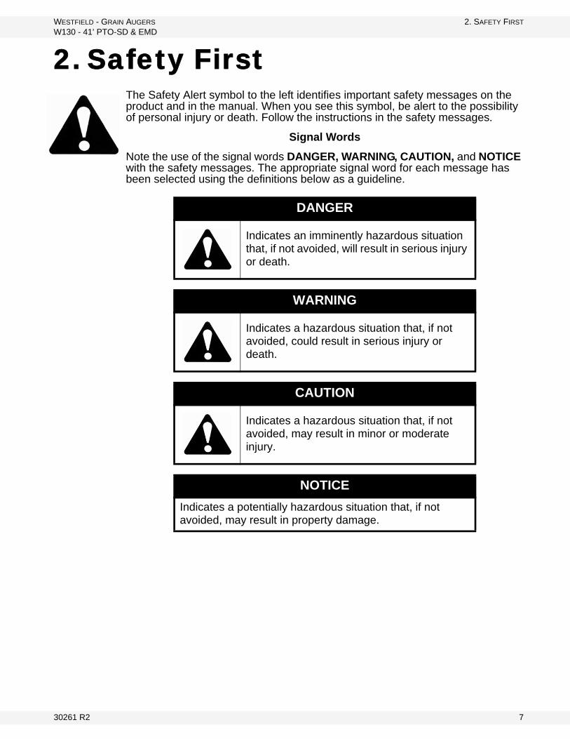
2. Safety FirstThe Safety Alert symbol to the left identifies important safety messages on the product and in the manual. When you see this symbol, be alert to the possibility of personal injury or death. Follow the instructions in the safety messages.
Signal Words
Note the use of the signal words DANGER, WARNING, CAUTION, and NOTICE with the safety messages. The appropriate signal word for each message has been selected using the definitions below as a guideline.
DANGER
Indicates an imminently hazardous situation that, if not avoided, will result in serious injury or death.
WARNING
Indicates a hazardous situation that, if not avoided, could result in serious injury or death.
CAUTION
Indicates a hazardous situation that, if not avoided, may result in minor or moderate injury.
NOTICE
Indicates a potentially hazardous situation that, if not avoided, may result in property damage.
30261 R2 7
2. SAFETY FIRST WESTFIELD - GRAIN AUGERS
W130 - 41’ PTO-SD & EMD
2.1. GENERAL SAFETY
Important: This general safety section includes instructions that apply to all safety practices. Any instructions specific to a certain safety practice (e.g., assembly safety), can be found in the appropriate section. Always read the complete instructional sections and not just these safety summaries before doing anything with the equipment.
YOU are responsible for the SAFE use and maintenance of your equipment. YOU must ensure that you and anyone else who is going to work around the equipment understands all procedures and related SAFETY information contained in all on-product labels and in this manual.
Remember, YOU are the key to safety. Good safety practices not only protect you, but also the people around you. Make these practices a working part of your safety program.
• It is the equipment owner, operator, and maintenance personnel’s responsi-bility to read and understand ALL safety instructions, safety decals, and man-uals and follow them when assembling, operating, or maintaining the equipment. All accidents can be avoided.
• Equipment owners must give instructions and review the information initially and annually with all personnel before allowing them to operate this product. Untrained users/operators expose themselves and bystanders to possible serious injury or death.
• Use this equipment for its intended purposes only.• Do not modify the equipment in any way that is not authorized by the manu-
facturer. Unauthorized modification may impair the function and/or safety, and could affect the life of the equipment. Any modification to the equipment voids the warranty.
• Do not allow anyone within the work area who doesn’t need to be there.• Follow all practices to ensure that the workplace is safe.• Have a first-aid kit available for use should the need arise, and know how to
use it.• Provide a fire extinguisher for use in case of an accident. Store in a highly vis-
ible and accessible place.• Wear appropriate protective gear. This list includes, but
is not limited to:• a hard hat• gloves• protective shoes with slip-resistant soles• protective goggles• hearing protection• dust mask or respirator
• For Powered Equipment: before servicing, adjusting, or repairing powered equipment, unplug, place all controls in neutral or off position, stop the engine or motor, remove ignition key or lock out power source, and wait for all mov-ing parts to stop.
8 30261 R2

WESTFIELD - GRAIN AUGERS 2. SAFETY FIRST
W130 - 41’ PTO-SD & EMD
• Follow good shop practices:• keep service area clean and dry• be sure electrical outlets and tools are properly
grounded• use adequate light for the job at hand• Think SAFETY! Work SAFELY!
2.2. ASSEMBLY SAFETY
• Read through the instructions to get to know the sub-assemblies and hard-ware that make up the equipment.
• Do not take chances with safety. The components are large, heavy, and can be hard to handle. Always use the proper tools, stands, jacks, and hoists for the job.
• Read and understand the assembly instructions for the product before pro-ceeding to assemble the product.
• Always have two or more people assembling the equipment. Because of the weight, do not attempt assembly alone.
2.3. OPERATION SAFETY
• Have another trained person nearby who can shut down the auger in case of accident. Always work with a second trained person around augers.
• Do not operate with any of the safety guards removed.• Keep body, hair, and clothing away from moving parts. Stay away from intake
during operation.• Inspect lift cable before using auger. Replace if frayed or damaged. Make
sure it is seated properly in cable sheaves and cable clamps are secure.• Operate auger on level ground free of debris. If ground is uneven, anchor the
auger to prevent tipping or upending.• Augers are not insulated. Keep away from electrical lines. Electrocution can
occur without direct contact.• Support the discharge end and/or anchor the intake end before operating to
prevent upending.• Do not use auger as a hoist.• Empty auger before raising or lowering.• Lower auger at completion of operation or when not in use. Auger could drop
rapidly in case of cable break or hydraulic failure (where applicable). • Ensure that winch is locked before operating auger.• Do not grab or touch drive belts during operation for any reason.
30261 R2 9

2. SAFETY FIRST WESTFIELD - GRAIN AUGERS
W130 - 41’ PTO-SD & EMD
Figure 2.1
2.4. PTO SAFETY
• Never use a PTO driveline without a rotating shield in good working order.• Ensure PTO driveline is securely attached at both ends before operating.• Before starting tractor, turn power to PTO to the off position (where applica-
ble).• Keep body, hair, and clothing away from rotating PTO driveline.• Ensure the PTO driveline shields turn freely on the PTO driveline.• Do not exceed operating speed of 540 rpm.• Keep u-joint angles small and equal. Do not exceed recommended operating
length for PTO driveline.
10 30261 R2
WESTFIELD - GRAIN AUGERS 2. SAFETY FIRST
W130 - 41’ PTO-SD & EMD
2.5. ELECTRIC MOTOR SAFETY
• Inspect the drive belts before using auger. Replace if frayed or damaged.• Do not grab or touch drive belts during operation for any reason.• Remember to ground electric motor before using auger.
2.6. TRANSPORT & PLACEMENT SAFETY
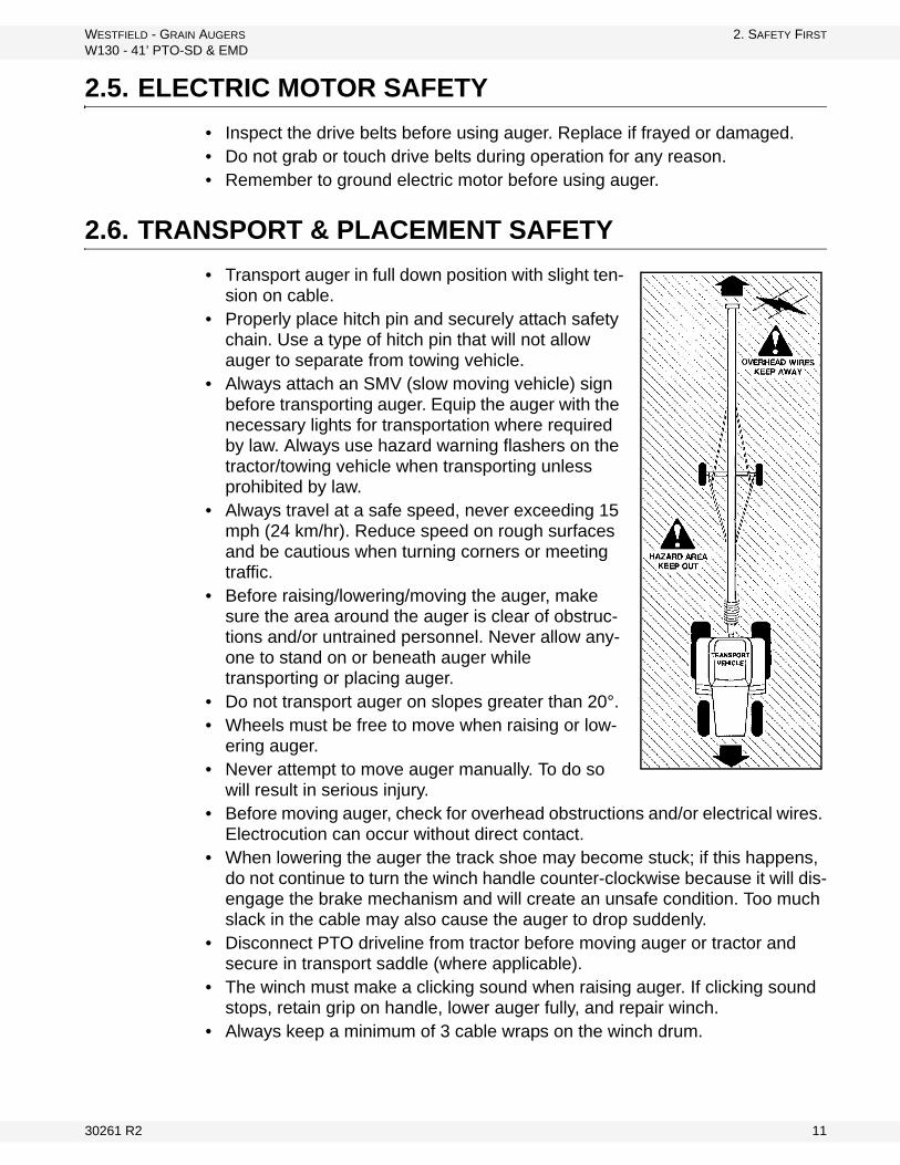
• Transport auger in full down position with slight ten-sion on cable.
• Properly place hitch pin and securely attach safety chain. Use a type of hitch pin that will not allow auger to separate from towing vehicle.
• Always attach an SMV (slow moving vehicle) sign before transporting auger. Equip the auger with the necessary lights for transportation where required by law. Always use hazard warning flashers on the tractor/towing vehicle when transporting unless prohibited by law.
• Always travel at a safe speed, never exceeding 15 mph (24 km/hr). Reduce speed on rough surfaces and be cautious when turning corners or meeting traffic.
• Before raising/lowering/moving the auger, make sure the area around the auger is clear of obstruc-tions and/or untrained personnel. Never allow any-one to stand on or beneath auger while transporting or placing auger.
• Do not transport auger on slopes greater than 20°.• Wheels must be free to move when raising or low-
ering auger.• Never attempt to move auger manually. To do so
will result in serious injury. • Before moving auger, check for overhead obstructions and/or electrical wires.
Electrocution can occur without direct contact.• When lowering the auger the track shoe may become stuck; if this happens,
do not continue to turn the winch handle counter-clockwise because it will dis-engage the brake mechanism and will create an unsafe condition. Too much slack in the cable may also cause the auger to drop suddenly.
• Disconnect PTO driveline from tractor before moving auger or tractor and secure in transport saddle (where applicable).
• The winch must make a clicking sound when raising auger. If clicking sound stops, retain grip on handle, lower auger fully, and repair winch.
• Always keep a minimum of 3 cable wraps on the winch drum.
30261 R2 11

2. SAFETY FIRST WESTFIELD - GRAIN AUGERS
W130 - 41’ PTO-SD & EMD
2.7. MAINTENANCE SAFETY
• Shut down and lock out all power before attempting maintenance of any kind. If applicable, disconnect PTO driveline from tractor or hydraulic hoses on units with hydraulic drive hoppers.
• After maintenance is complete, replace and secure all safety guards and safety devices, and if applicable, service doors and cleanout covers.
• Support auger tube before attempting maintenance on the undercarriage assembly. Auger should be in full down position for maintenance.
• Use only genuine Westfield replacement parts or equivalent. Replacement parts such as intake guards, pulley guards, PTO driveline shields, winches, and lift cables must meet ASABE standards or serious injury may result. Use of unauthorized parts will void warranty. If in doubt, contact Westfield or your Westfield dealer.
• Do not modify any auger components without authorization from Westfield. Modification can be dangerous and result in serious injuries.
2.8. SAFETY DECALS
• Keep safety decals clean and legible at all times.• Replace safety decals that are missing or have become illegible. See decal
location figures that follow.• Replaced parts must display the same decal(s) as the original part.• Safety decals are available from your distributor, dealer, or factory.
2.8.1. DECAL INSTALLATION
1. Decal area must be clean and dry, with a temperature above 50°F (10°C).2. Decide on the exact position before you remove the backing paper.3. Align the decal over the specified area and carefully press the small portion
with the exposed sticky backing in place.4. Slowly peel back the remaining paper and carefully smooth the remaining
portion of the decal in place.5. Small air pockets can be pierced with a pin and smoothed out using the sign
backing paper.
2.8.2. SAFETY DECAL LOCATIONS
Replicas of the safety decals that are attached to the equipment are shown in the figure(s) that follow. Proper safety procedures require that you familiarize yourself with the various safety decals and the areas or particular functions that the decals apply to as well as the safety precautions that must be taken to avoid serious injury, death, or damage.
* Westfield reserves the right to update safety decals without notice. Safety decals may not be exactly as shown.
12 30261 R2

WESTFIELD - GRAIN AUGERS 2. SAFETY FIRST
W130 - 41’ PTO-SD & EMD
Figure 2.2
DECAL #17101
DECAL #17102
DECAL #17098DECAL #17097
PLACED ON MACHINE BEHIND GUARD
DECAL #27709
30261 R2 13
2. SAFETY FIRST WESTFIELD - GRAIN AUGERS
W130 - 41’ PTO-SD & EMD
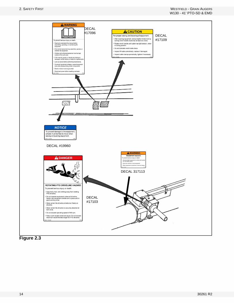
Figure 2.3
DECAL #17096
DECAL #17109
DECAL #19960
DECAL #17103
DECAL 317113
14 30261 R2
WESTFIELD - GRAIN AUGERS 3. ASSEMBLY
W130 - 41’ PTO-SD & EMD
3. Assembly
3.1. PRE-ASSEMBLY
Before beginning assembly, familiarize yourself with all the sub-assemblies and hardware making up the auger. Have all parts on hand and arrange them for easy access. Carry out assembly in a large open area with a level surface.
Important: Always have 2 or more people assembling the equipment. Because of the weight, do not attempt assembly alone.
Augers are available in various combinations. In most cases, the following instructions will apply to all augers. Where the assembly information varies, additional instructions will be included and will be indicated with an arrow.
3.2. TUBES & FLIGHTING
1. Position tube sections. Align tube sections on a flat surface or on a series of benches.
Note: When assembling more than 2 sections, start from spout end and work towards hopper.
Warning: Before continuing, ensure you have read and understand the relevant information in the safety section. Safety information is provided to help prevent serious injury, death, or property damage.
WARNING
Do not drop. Damage to equipment or serious personal injury will result.
30261 R2 15
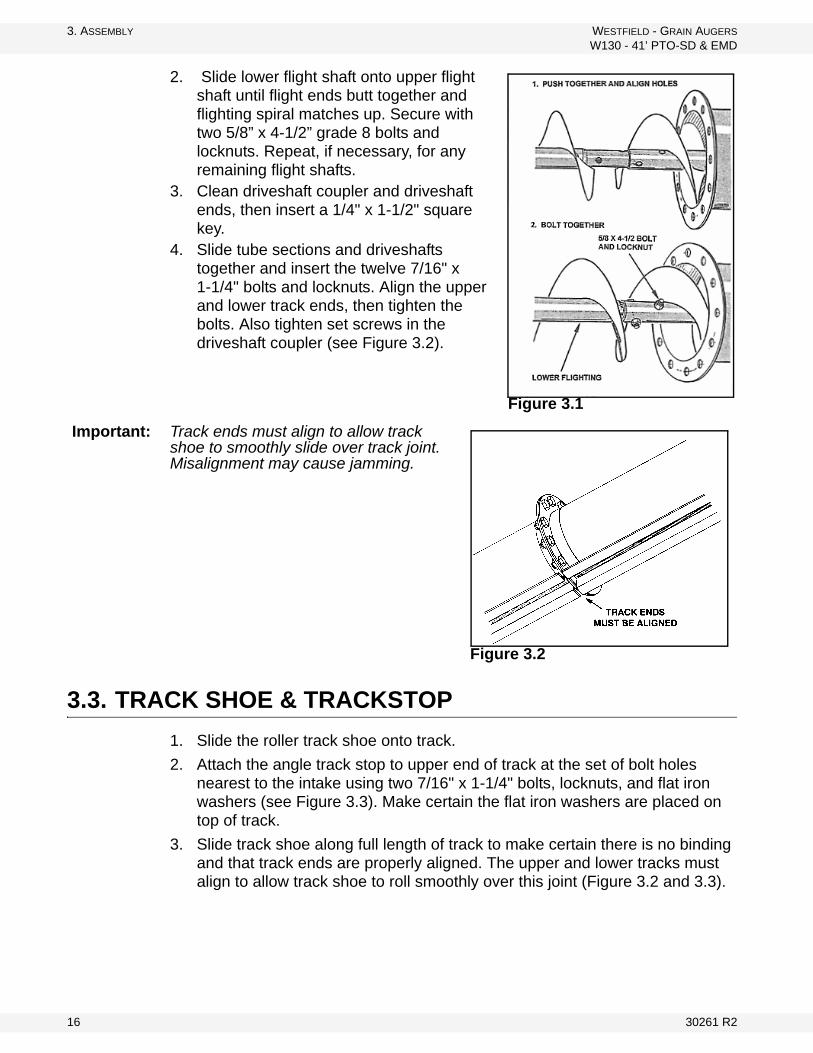
3. ASSEMBLY WESTFIELD - GRAIN AUGERS
W130 - 41’ PTO-SD & EMD
2. Slide lower flight shaft onto upper flight shaft until flight ends butt together and flighting spiral matches up. Secure with two 5/8” x 4-1/2” grade 8 bolts and locknuts. Repeat, if necessary, for any remaining flight shafts.
3. Clean driveshaft coupler and driveshaft ends, then insert a 1/4" x 1-1/2" square key.
4. Slide tube sections and driveshafts together and insert the twelve 7/16" x 1-1/4" bolts and locknuts. Align the upper and lower track ends, then tighten the bolts. Also tighten set screws in the driveshaft coupler (see Figure 3.2).
Important: Track ends must align to allow track shoe to smoothly slide over track joint. Misalignment may cause jamming.
3.3. TRACK SHOE & TRACKSTOP
1. Slide the roller track shoe onto track.
2. Attach the angle track stop to upper end of track at the set of bolt holes nearest to the intake using two 7/16" x 1-1/4" bolts, locknuts, and flat iron washers (see Figure 3.3). Make certain the flat iron washers are placed on top of track.
3. Slide track shoe along full length of track to make certain there is no binding and that track ends are properly aligned. The upper and lower tracks must align to allow track shoe to roll smoothly over this joint (Figure 3.2 and 3.3).
Figure 3.1
Figure 3.2
16 30261 R2
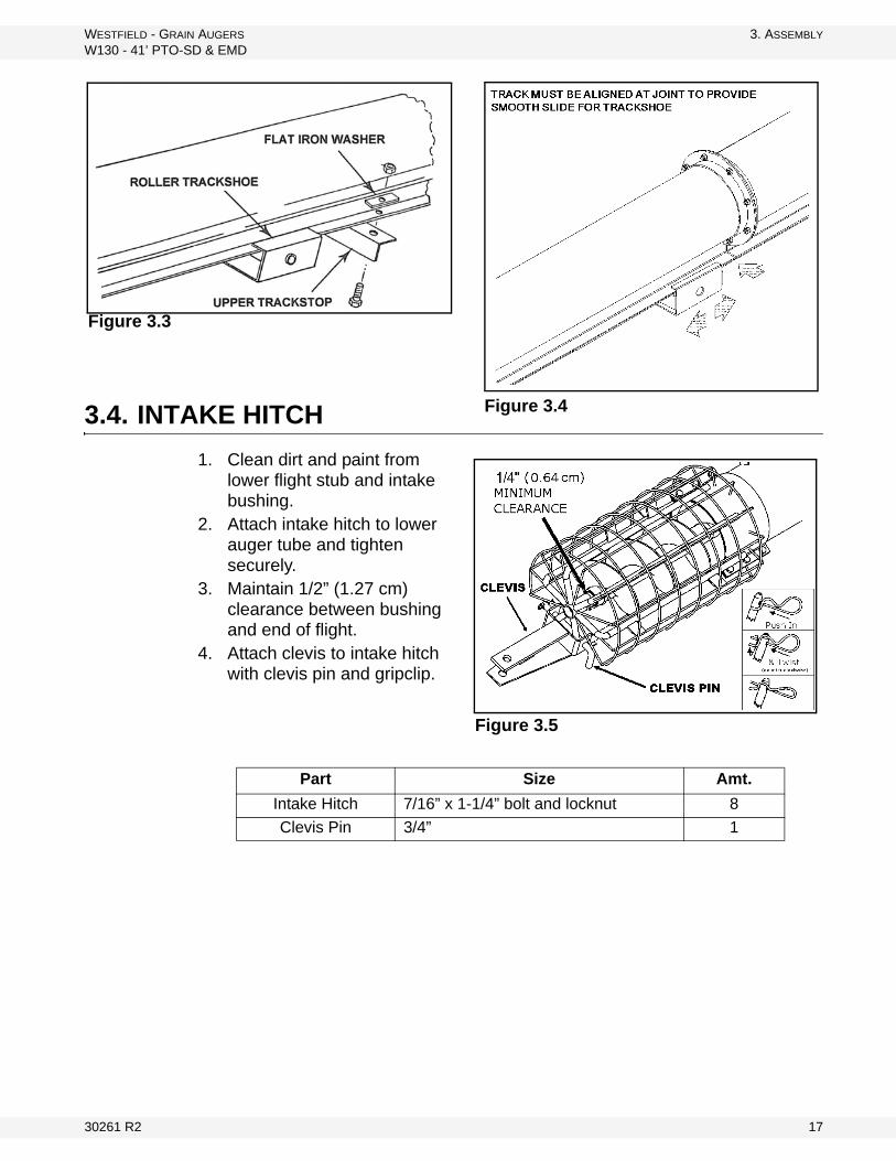
WESTFIELD - GRAIN AUGERS 3. ASSEMBLY
W130 - 41’ PTO-SD & EMD
3.4. INTAKE HITCH
1. Clean dirt and paint from lower flight stub and intake bushing.
2. Attach intake hitch to lower auger tube and tighten securely.
3. Maintain 1/2” (1.27 cm) clearance between bushing and end of flight.
4. Attach clevis to intake hitch with clevis pin and gripclip.
Figure 3.4
Figure 3.3
Part Size Amt.
Intake Hitch 7/16” x 1-1/4” bolt and locknut 8
Clevis Pin 3/4” 1
Figure 3.5
30261 R2 17
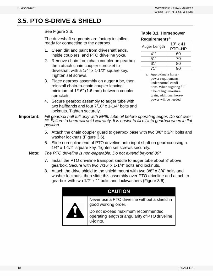
3. ASSEMBLY WESTFIELD - GRAIN AUGERS
W130 - 41’ PTO-SD & EMD
3.5. PTO S-DRIVE & SHIELD
See Figure 3.6.
The driveshaft segments are factory installed, ready for connecting to the gearbox.
1. Clean dirt and paint from driveshaft ends, inside couplers, and PTO driveline yoke.
2. Remove chain from chain coupler on gearbox, then attach chain coupler sprocket to driveshaft with a 1/4" x 1-1/2" square key. Tighten set screws.
3. Place gearbox assembly on auger tube, then reinstall chain-to-chain coupler leaving minimum of 1/16" (1.6 mm) between coupler sprockets.
4. Secure gearbox assembly to auger tube with two halfbands and four 7/16" x 1-1/4" bolts and locknuts. Tighten securely.
Important: Fill gearbox half full only with EP90 lube oil before operating auger. Do not over fill. Failure to heed will void warranty. It is easier to fill oil into gearbox when in flat position.
5. Attach the chain coupler guard to gearbox base with two 3/8" x 3/4" bolts and washer locknuts (Figure 3.6).
6. Slide non-spline end of PTO driveline onto input shaft on gearbox using a 1/4" x 1-1/2" square key. Tighten set screws securely.
Note: The PTO driveline is non-separable. Do not extend beyond 80".
7. Install the PTO driveline transport saddle to auger tube about 3’ above gearbox. Secure with two 7/16” x 1-1/4" bolts and locknuts.
8. Attach the drive shield to the shield mount with two 3/8" x 3/4" bolts and washer locknuts, then slide this assembly over PTO driveline and attach to gearbox with two 1/2” x 1" bolts and lockwashers (Figure 3.6).
Table 3.1. Horsepower
Requirementsa
a. Approximate horse-power requirements under normal condi-tions. When augering full tube of high moisture grain, additional horse-power will be needed.
Auger Length13” x 41’ PTO–HP
41’ 6051’ 7061’ 8071’ 90
CAUTION
Never use a PTO driveline without a shield in good working order.
Do not exceed maximum recommended operating length or angularity of PTO driveline u-joints.
18 30261 R2

WESTFIELD - GRAIN AUGERS 3. ASSEMBLY
W130 - 41’ PTO-SD & EMD
Figure 3.6
3.6. EMD DRIVE
See Figure 3.7 and 3.8.
1. Remove the driveshaft segment nearest the intake end of auger (9’9" long). This driveshaft is not used on EMD augers.
2. Clean dirt and paint from driveshaft ends and inside couplers.
3. Remove and discard driveshaft bearing at third bearing bracket from intake end.
4. Remove chain from chain coupler on gearbox, then attach chain coupler sprocket to driveshaft with a 1/4" x 1-1/2" square key. Tighten set screw.
5. Place gearbox assembly on auger tube, then reinstall chain coupler leaving minimum of 1/16" between coupler sprockets.
6. Secure gearbox assembly to auger tube with two halfbands and four 7/16" x 1-1/4" bolts and locknuts. Tighten securely.
7. Attach the chain coupler guard to gearbox base with two 3/8" x 3/4" bolts and washer locknuts.
Important: Fill gearbox half full with EP90 lube oil before operating auger. Do not overfill. Failure to heed will void warranty. It is easier to fill oil into the gearbox when it is in the horizontal position.
Table 3.2. Horsepower
Requirementsa
a. Approximate horsepower requirements under normal conditions. When augering full tube of high moisture grain, additional horsepower will be needed.
Auger Length13” x 41’
ELECTRIC– HP41’ 20
30261 R2 19
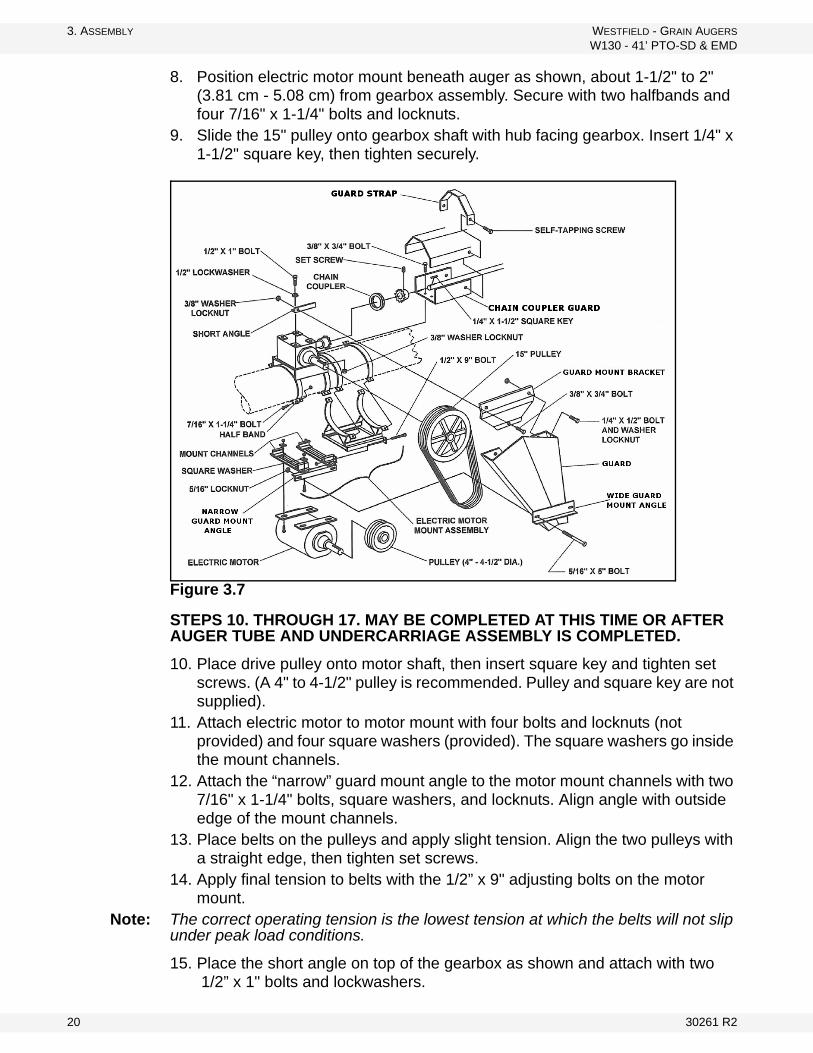
3. ASSEMBLY WESTFIELD - GRAIN AUGERS
W130 - 41’ PTO-SD & EMD
8. Position electric motor mount beneath auger as shown, about 1-1/2" to 2" (3.81 cm - 5.08 cm) from gearbox assembly. Secure with two halfbands and four 7/16" x 1-1/4" bolts and locknuts.
9. Slide the 15" pulley onto gearbox shaft with hub facing gearbox. Insert 1/4" x 1-1/2" square key, then tighten securely.
Figure 3.7
STEPS 10. THROUGH 17. MAY BE COMPLETED AT THIS TIME OR AFTER AUGER TUBE AND UNDERCARRIAGE ASSEMBLY IS COMPLETED.
10. Place drive pulley onto motor shaft, then insert square key and tighten set screws. (A 4" to 4-1/2" pulley is recommended. Pulley and square key are not supplied).
11. Attach electric motor to motor mount with four bolts and locknuts (not provided) and four square washers (provided). The square washers go inside the mount channels.
12. Attach the “narrow” guard mount angle to the motor mount channels with two 7/16" x 1-1/4" bolts, square washers, and locknuts. Align angle with outside edge of the mount channels.
13. Place belts on the pulleys and apply slight tension. Align the two pulleys with a straight edge, then tighten set screws.
14. Apply final tension to belts with the 1/2” x 9" adjusting bolts on the motor mount.
Note: The correct operating tension is the lowest tension at which the belts will not slip under peak load conditions.
15. Place the short angle on top of the gearbox as shown and attach with two 1/2” x 1" bolts and lockwashers.
20 30261 R2
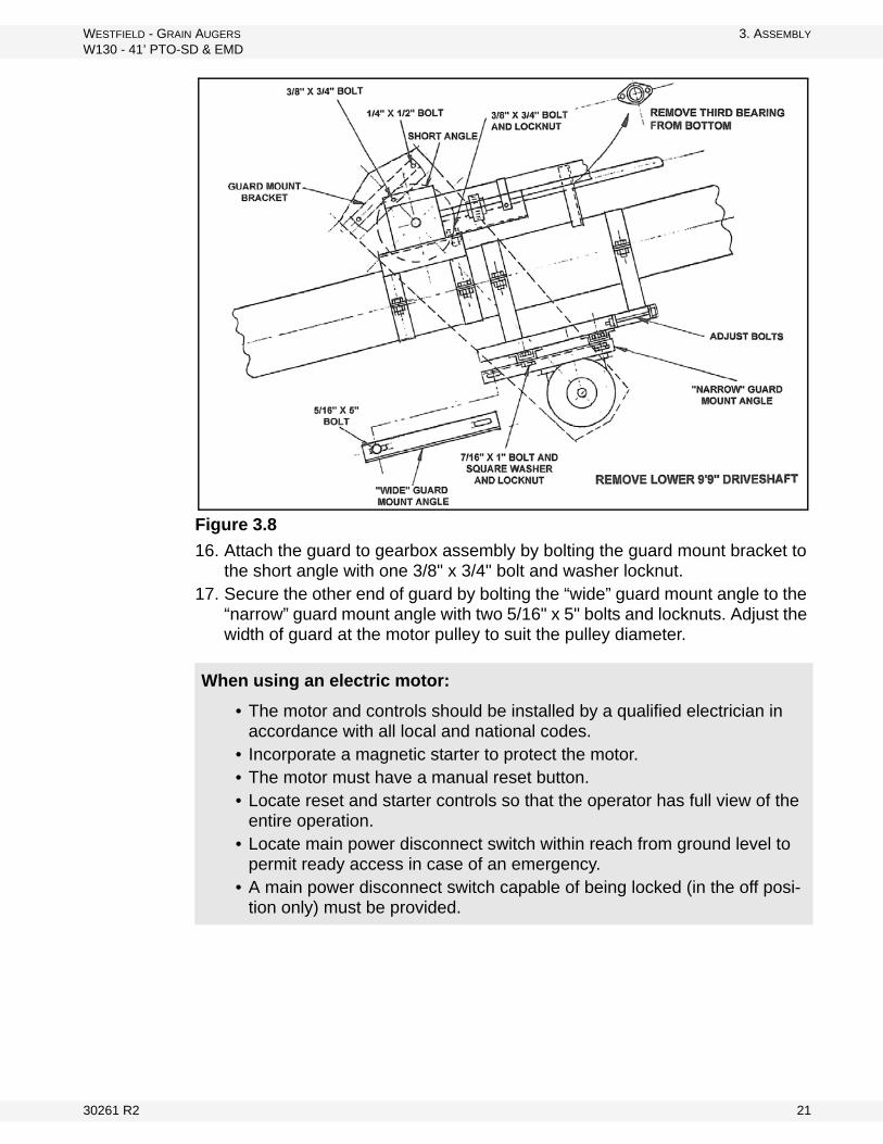
WESTFIELD - GRAIN AUGERS 3. ASSEMBLY
W130 - 41’ PTO-SD & EMD
Figure 3.8
16. Attach the guard to gearbox assembly by bolting the guard mount bracket to the short angle with one 3/8" x 3/4" bolt and washer locknut.
17. Secure the other end of guard by bolting the “wide” guard mount angle to the “narrow” guard mount angle with two 5/16" x 5" bolts and locknuts. Adjust the width of guard at the motor pulley to suit the pulley diameter.
When using an electric motor:
• The motor and controls should be installed by a qualified electrician in accordance with all local and national codes.
• Incorporate a magnetic starter to protect the motor.• The motor must have a manual reset button.• Locate reset and starter controls so that the operator has full view of the
entire operation.• Locate main power disconnect switch within reach from ground level to
permit ready access in case of an emergency.• A main power disconnect switch capable of being locked (in the off posi-
tion only) must be provided.
30261 R2 21
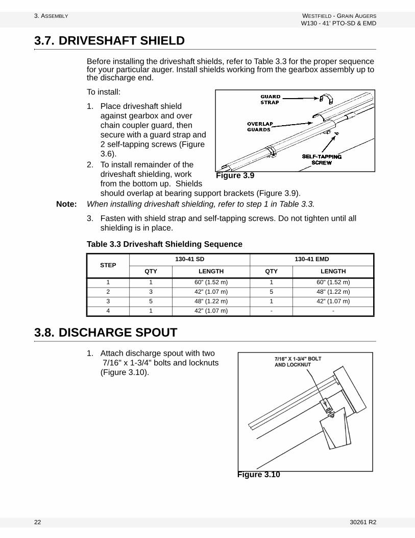
3. ASSEMBLY WESTFIELD - GRAIN AUGERS
W130 - 41’ PTO-SD & EMD
3.7. DRIVESHAFT SHIELD
Before installing the driveshaft shields, refer to Table 3.3 for the proper sequence for your particular auger. Install shields working from the gearbox assembly up to the discharge end.
To install:
1. Place driveshaft shield against gearbox and over chain coupler guard, then secure with a guard strap and 2 self-tapping screws (Figure 3.6).
2. To install remainder of the driveshaft shielding, work from the bottom up. Shields should overlap at bearing support brackets (Figure 3.9).
Note: When installing driveshaft shielding, refer to step 1 in Table 3.3.
3. Fasten with shield strap and self-tapping screws. Do not tighten until all shielding is in place.
3.8. DISCHARGE SPOUT
1. Attach discharge spout with two 7/16" x 1-3/4" bolts and locknuts (Figure 3.10).
Figure 3.9
Table 3.3 Driveshaft Shielding Sequence
STEP130-41 SD 130-41 EMD
QTY LENGTH QTY LENGTH
1 1 60” (1.52 m) 1 60" (1.52 m)
2 3 42” (1.07 m) 5 48" (1.22 m)
3 5 48” (1.22 m) 1 42” (1.07 m)
4 1 42” (1.07 m) - -
Figure 3.10
22 30261 R2

WESTFIELD - GRAIN AUGERS 3. ASSEMBLY
W130 - 41’ PTO-SD & EMD
3.9. TRANSPORT UNDERCARRIAGE
See Figure 3.11 to 3.15.
1. To assemble undercarriage, fasten the lower reach arms to axle with three 7/16" x 1-1/4" bolts and locknuts on each side.
2. Attach long crossmember to bottom of undercarriage brackets as shown, with two 7/16" x 1-1/4" bolts and locknuts.
3. Attach the short crossmember to lower reach arms with two 1/2” x 1-1/4" bolts and locknuts.
Figure 3.11
4. Wheel hub assembly:a. Remove any dirt or paint from spindle and hub.
b. Thoroughly pack wheel bearings and cups with a good grade of bearing grease.
c. Place large bearing into hub and carefully tap in seal.
d. Slip hub onto spindle and insert small bearing.
e. Tighten slotted spindle nut until hub drags slightly. Back off nut about 1/4 turn until hub turns freely.
f. Install cotter pin and dust cap.
Note: Installing tires may not leave you with enough clearance to position and attach undercarriage once auger tube is raised. If so, install wheels after assembly is complete.
g. Check that pressure of pre-inflated tires matches pressure indicated on tire sidewall. Mount wheels on hubs and attach with six 1/2” x 1-3/4” wheel bolts.
30261 R2 23
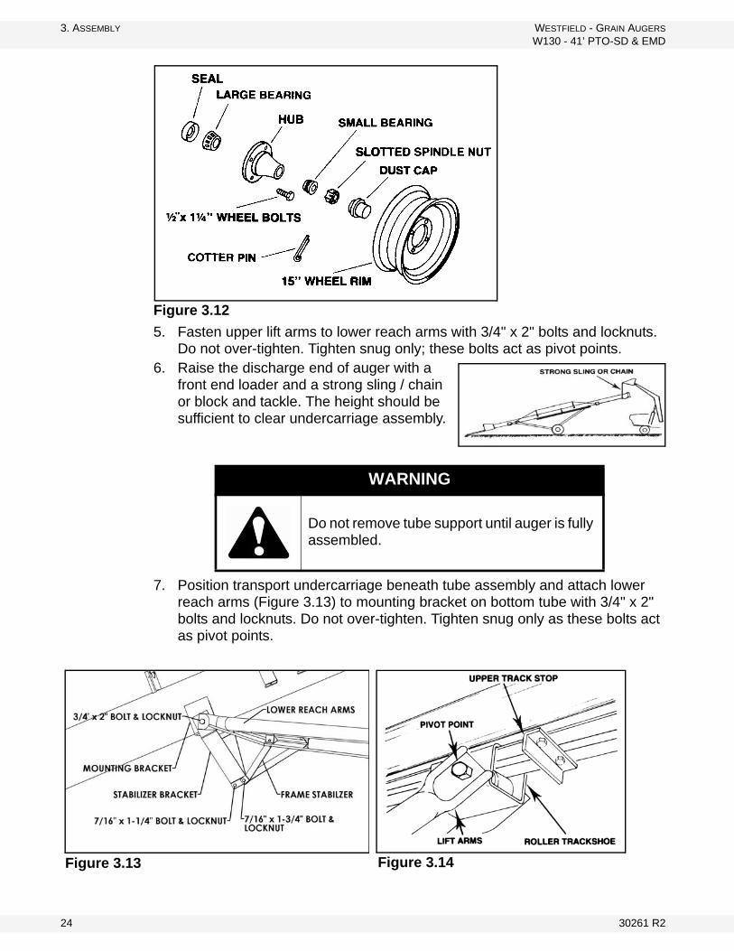
3. ASSEMBLY WESTFIELD - GRAIN AUGERS
W130 - 41’ PTO-SD & EMD
Figure 3.12
5. Fasten upper lift arms to lower reach arms with 3/4" x 2" bolts and locknuts. Do not over-tighten. Tighten snug only; these bolts act as pivot points.
6. Raise the discharge end of auger with a front end loader and a strong sling / chain or block and tackle. The height should be sufficient to clear undercarriage assembly.
7. Position transport undercarriage beneath tube assembly and attach lower reach arms (Figure 3.13) to mounting bracket on bottom tube with 3/4" x 2" bolts and locknuts. Do not over-tighten. Tighten snug only as these bolts act as pivot points.
WARNING
Do not remove tube support until auger is fully assembled.
Figure 3.14 Figure 3.13
24 30261 R2
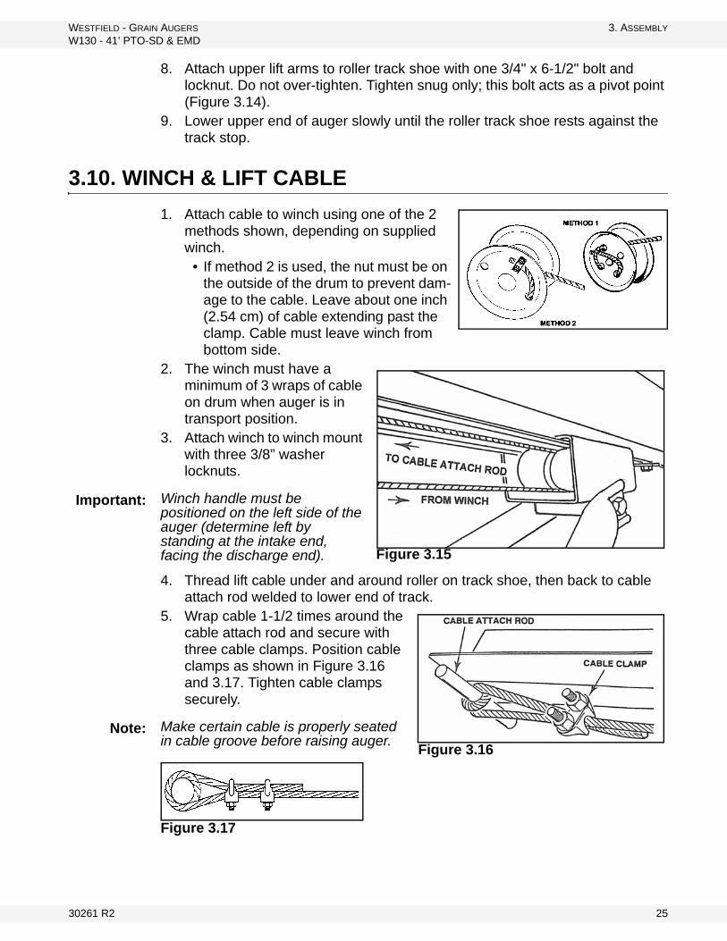
WESTFIELD - GRAIN AUGERS 3. ASSEMBLY
W130 - 41’ PTO-SD & EMD
8. Attach upper lift arms to roller track shoe with one 3/4" x 6-1/2" bolt and locknut. Do not over-tighten. Tighten snug only; this bolt acts as a pivot point (Figure 3.14).
9. Lower upper end of auger slowly until the roller track shoe rests against the track stop.
3.10. WINCH & LIFT CABLE
1. Attach cable to winch using one of the 2 methods shown, depending on supplied winch.
• If method 2 is used, the nut must be on the outside of the drum to prevent dam-age to the cable. Leave about one inch (2.54 cm) of cable extending past the clamp. Cable must leave winch from bottom side.
2. The winch must have a minimum of 3 wraps of cable on drum when auger is in transport position.
3. Attach winch to winch mount with three 3/8” washer locknuts.
Winch handle must be positioned on the left side of the auger (determine left by standing at the intake end, facing the discharge end).
4. Thread lift cable under and around roller on track shoe, then back to cable attach rod welded to lower end of track.
5. Wrap cable 1-1/2 times around the cable attach rod and secure with three cable clamps. Position cable clamps as shown in Figure 3.16 and 3.17. Tighten cable clamps securely.
Make certain cable is properly seated in cable groove before raising auger.
Figure 3.17
Figure 3.15
Important:
Figure 3.16
Note:
30261 R2 25

3. ASSEMBLY WESTFIELD - GRAIN AUGERS
W130 - 41’ PTO-SD & EMD
3.10.1. WINCH HANDLE
This auger may use one of several different winch models. Before installing handle on the main winch assembly, check the model number stamped on winch housing and follow the correct set of instructions.
MODEL K2550
1. Slide handle over flat sides of input shaft.
2. Fasten with 1/2” locknut.
Do not remove or loosen the locknut on brake side of winch: it is an important part of the brake system of the winch.
3.11. UPPER HOUSING LUBRICATION
Fill enclosed upper drive housing with grease.
For continuous use in extreme cold conditions, semi-fluid arctic grease or heavy oil may be used.
3.12. PLASTIC MANUAL HOLDER
Before beginning installation, ensure that all winch / auger lift controls are locked in place and shut down and/or lock out auger.
1. Attach holder to the lower frame arms. Manual holder must be accessible at all times, whether frame is up or down.
2. The manual holder cap must face up (towards the intake end). Attach manual holder with supplied zip ties. Tighten the zip ties, securing the holder in place.
Where possible, attach the zip ties above a frame brace tab to prevent the manual holder from slipping down the lower frame arms.
CAUTION
Winch handle assembly must follow the instructions below. Improper assembly will result in sudden winch failure causing damage to equipment and/or personal injury.
Figure 3.18
Important:
2200 g 78 oz
LOWER REACH ARMS
PLASTIC ZIP TIES
CAP FACING INTAKE
Figure 3.19 Note:
26 30261 R2
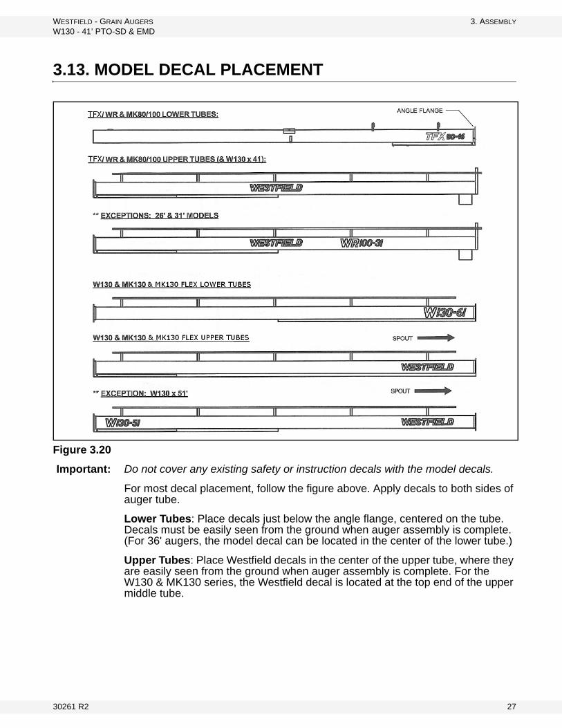
WESTFIELD - GRAIN AUGERS 3. ASSEMBLY
W130 - 41’ PTO-SD & EMD
3.13. MODEL DECAL PLACEMENT
Figure 3.20
Important: Do not cover any existing safety or instruction decals with the model decals.
For most decal placement, follow the figure above. Apply decals to both sides of auger tube.
Lower Tubes: Place decals just below the angle flange, centered on the tube. Decals must be easily seen from the ground when auger assembly is complete. (For 36' augers, the model decal can be located in the center of the lower tube.)
Upper Tubes: Place Westfield decals in the center of the upper tube, where they are easily seen from the ground when auger assembly is complete. For the W130 & MK130 series, the Westfield decal is located at the top end of the upper middle tube.
30261 R2 27

3. ASSEMBLY WESTFIELD - GRAIN AUGERS
W130 - 41’ PTO-SD & EMD
28 30261 R2
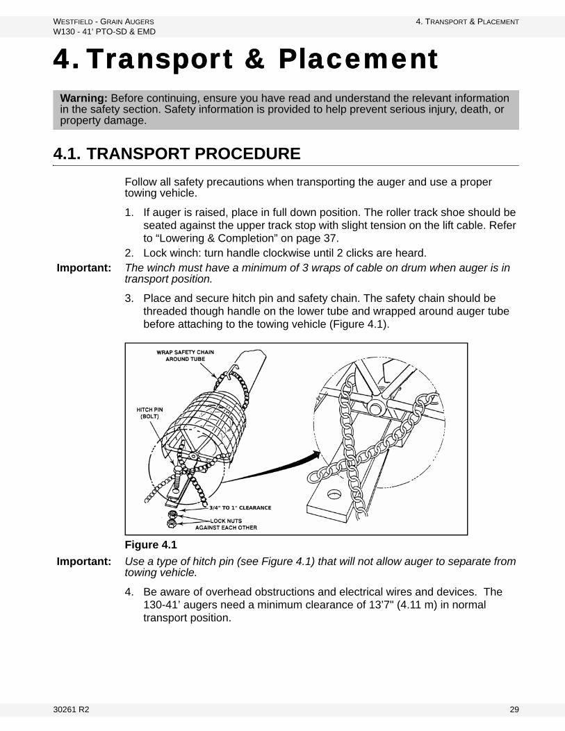
WESTFIELD - GRAIN AUGERS 4. TRANSPORT & PLACEMENT
W130 - 41’ PTO-SD & EMD
4. Transport & Placement
4.1. TRANSPORT PROCEDURE
Follow all safety precautions when transporting the auger and use a proper towing vehicle.
1. If auger is raised, place in full down position. The roller track shoe should be seated against the upper track stop with slight tension on the lift cable. Refer to “Lowering & Completion” on page 37.
2. Lock winch: turn handle clockwise until 2 clicks are heard.Important: The winch must have a minimum of 3 wraps of cable on drum when auger is in
transport position.
3. Place and secure hitch pin and safety chain. The safety chain should be threaded though handle on the lower tube and wrapped around auger tube before attaching to the towing vehicle (Figure 4.1).
Figure 4.1
Important: Use a type of hitch pin (see Figure 4.1) that will not allow auger to separate from towing vehicle.
4. Be aware of overhead obstructions and electrical wires and devices. The 130-41’ augers need a minimum clearance of 13’7" (4.11 m) in normal transport position.
Warning: Before continuing, ensure you have read and understand the relevant information in the safety section. Safety information is provided to help prevent serious injury, death, or property damage.
30261 R2 29
4. TRANSPORT & PLACEMENT WESTFIELD - GRAIN AUGERS
W130 - 41’ PTO-SD & EMD
5. Refer to “Transport & Placement Safety” on page 11 for important safety information before towing.
4.2. PLACEMENT PROCEDURE
1. Ensure towing hitch is in place and secure.Important: Use a type of hitch pin (Figure 4.1) that will not allow auger to separate from
towing vehicle.
2. Before raising or positioning auger, make sure that entire area in line of travel, both on the ground and overhead, is clear of any obstructions or electrical wires.
3. Ensure auger is on reasonably level ground when raising, lowering, or positioning.
Note: Make certain cable is properly seated in cable groove before raising auger. Refer to Figure 3.25.
4. To raise auger, turn winch handle clockwise. Use a firm grip on winch handle; do not release unless the ratchet pawl is fully engaged.
Important: Winch must make clicking sound when raising auger. If clicking stops, retain grip on handle, lower auger fully, and repair ratchet.
5. To raise auger, turn winch handle clockwise. Use a firm grip on winch handle; do not release unless the ratchet pawl is fully engaged.
Note: Do not turn winch handle counter-clockwise except when lowering auger or severe damage to winch will occur.
CAUTION
If auger wheels are partially or fully buried in snow or grain, failure to clear area around the wheels before moving may cause damage to the auger or result in serious injury.
WARNING
If auger wheels are partially or fully buried in snow or grain, failure to clear the area around the wheels before moving may cause damage to the auger or result in serious injury.
NOTICE
Do not turn winch handle counter-clockwise except when lowering auger or severe damage to winch will occur.
30 30261 R2
WESTFIELD - GRAIN AUGERS 4. TRANSPORT & PLACEMENT
W130 - 41’ PTO-SD & EMD
PTO Models Only: The driveline is non-separable. Remove from tractor and secure in transport saddle on auger before moving tractor away from auger.
6. Move the auger into working position slowly. Do not unhitch and attempt to move auger by hand.
7. Once auger is in position, chock wheels on both sides and apply the park brake on the tractor (or chock its wheels as well) to prevent movement during operation.
Important: When releasing auger from the towing vehicle, test the intake end for downward weight. Do not raise the intake end above drawbar height. When the intake end is elevated too high with auger in raised position, the balance of weight quickly transfers to the discharge end, causing it to upend. Ensure proper anchoring/support.
8. When operating auger in the raised position, rest the discharge end lightly on the bin roof, or tie to bin to prevent wind from toppling auger. When operating the auger in a freestanding position, anchor the intake end.
9. Anchor and/or support auger during operation.• When lower half of auger empties of grain, the weight balance transfers
to upper end of auger, which can cause upending.10. See “Lowering & Completion” on page 37 for correct lowering procedure.
WARNING
Never attempt to increase height of auger by positioning wheels on lumber, clocks, or by any other means. To do so will result in damage to equipment and/or personal injury.
CAUTION
Do not use auger as a hoist to raise any object regardless of weight. This will create an unsafe condition and will void warranty.
30261 R2 31

4. TRANSPORT & PLACEMENT WESTFIELD - GRAIN AUGERS
W130 - 41’ PTO-SD & EMD
32 30261 R2
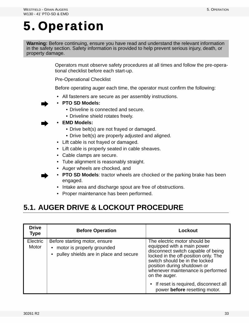
WESTFIELD - GRAIN AUGERS 5. OPERATION
W130 - 41’ PTO-SD & EMD
5. Operation
Operators must observe safety procedures at all times and follow the pre-opera-tional checklist before each start-up.
Pre-Operational Checklist
Before operating auger each time, the operator must confirm the following:
• All fasteners are secure as per assembly instructions.
• PTO SD Models: • Driveline is connected and secure.• Driveline shield rotates freely.
• EMD Models: • Drive belt(s) are not frayed or damaged.• Drive belt(s) are properly adjusted and aligned.
• Lift cable is not frayed or damaged.• Lift cable is properly seated in cable sheaves.• Cable clamps are secure.• Tube alignment is reasonably straight.• Auger wheels are chocked, and
• PTO SD Models: tractor wheels are chocked or the parking brake has been engaged.
• Intake area and discharge spout are free of obstructions.• Proper maintenance has been performed.
5.1. AUGER DRIVE & LOCKOUT PROCEDURE
Warning: Before continuing, ensure you have read and understand the relevant information in the safety section. Safety information is provided to help prevent serious injury, death, or property damage.
Drive Type
Before Operation Lockout
Electric Motor
Before starting motor, ensure• motor is properly grounded• pulley shields are in place and secure
The electric motor should be equipped with a main power disconnect switch capable of being locked in the off-position only. The switch should be in the locked position during shutdown or whenever maintenance is performed on the auger.
• If reset is required, disconnect all power before resetting motor.
30261 R2 33

5. OPERATION WESTFIELD - GRAIN AUGERS
W130 - 41’ PTO-SD & EMD
5.2. OPERATING PROCEDURE
5.2.1. START-UP & BREAK IN
1. Properly place auger and complete the pre-operational checklist at the beginning of this chapter. If everything is satisfactory, prepare for a 30 minute operation (half speed for PTO).
2. Correctly position portable grain hopper secure it to the auger with both straps (where applicable).
Important: Anchoring and/or support auger during operation. When lower half of auger empties of grain, the weight balance transfers to the upper end of auger, which can cause upending.
3. Start tractor and engage PTO driveline or start electric motor (depending on model), then feed grain to auger.
4. PTO Models: If auger functions normally, check PTO drive at varying speeds for a period of 30 minutes.
Important: When starting auger for the first time, be prepared for an emergency shutdown in case of excessive vibration or noise. Note that auger may run rough until tube is polished.
5. Upon completion of initial run, shutdown auger (see section below for more information on shutting down your auger).
6. Lock out tractor and conduct a complete inspection of auger following the checklist at the beginning of this chapter.
PTO Drive-line
Before starting, ensure
• PTO driveline is securely attached to the tractor and jackhaft
• tractor park brake in engaged and/or wheels are chocked
• you are not exceeding the maximum operating length of 80” (2016 mm) of the PTO driveline or maximum angle of 15°
• PTO drive on the tractor is in the off position
Shut off tractor’s engine and remove key from tractor.
• If removing key is impossible, remove PTO driveline from trac-tor.
Drive Type
Before Operation Lockout
CAUTION
Do not start auger until area is clear of all unauthorized personnel.
Do not exceed 540 rpm on the PTO.
34 30261 R2
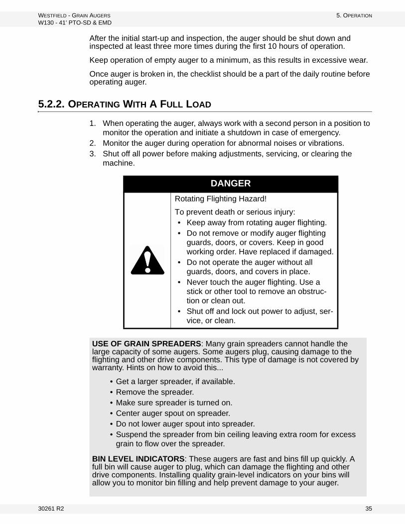
WESTFIELD - GRAIN AUGERS 5. OPERATION
W130 - 41’ PTO-SD & EMD
After the initial start-up and inspection, the auger should be shut down and inspected at least three more times during the first 10 hours of operation.
Keep operation of empty auger to a minimum, as this results in excessive wear.
Once auger is broken in, the checklist should be a part of the daily routine before operating auger.
5.2.2. OPERATING WITH A FULL LOAD
1. When operating the auger, always work with a second person in a position to monitor the operation and initiate a shutdown in case of emergency.
2. Monitor the auger during operation for abnormal noises or vibrations.3. Shut off all power before making adjustments, servicing, or clearing the
machine.
DANGER
Rotating Flighting Hazard!
To prevent death or serious injury:• Keep away from rotating auger flighting.• Do not remove or modify auger flighting
guards, doors, or covers. Keep in good working order. Have replaced if damaged.
• Do not operate the auger without all guards, doors, and covers in place.
• Never touch the auger flighting. Use a stick or other tool to remove an obstruc-tion or clean out.
• Shut off and lock out power to adjust, ser-vice, or clean.
USE OF GRAIN SPREADERS: Many grain spreaders cannot handle the large capacity of some augers. Some augers plug, causing damage to the flighting and other drive components. This type of damage is not covered by warranty. Hints on how to avoid this...
• Get a larger spreader, if available.• Remove the spreader.• Make sure spreader is turned on.• Center auger spout on spreader.• Do not lower auger spout into spreader.• Suspend the spreader from bin ceiling leaving extra room for excess
grain to flow over the spreader.
BIN LEVEL INDICATORS: These augers are fast and bins fill up quickly. A full bin will cause auger to plug, which can damage the flighting and other drive components. Installing quality grain-level indicators on your bins will allow you to monitor bin filling and help prevent damage to your auger.
30261 R2 35
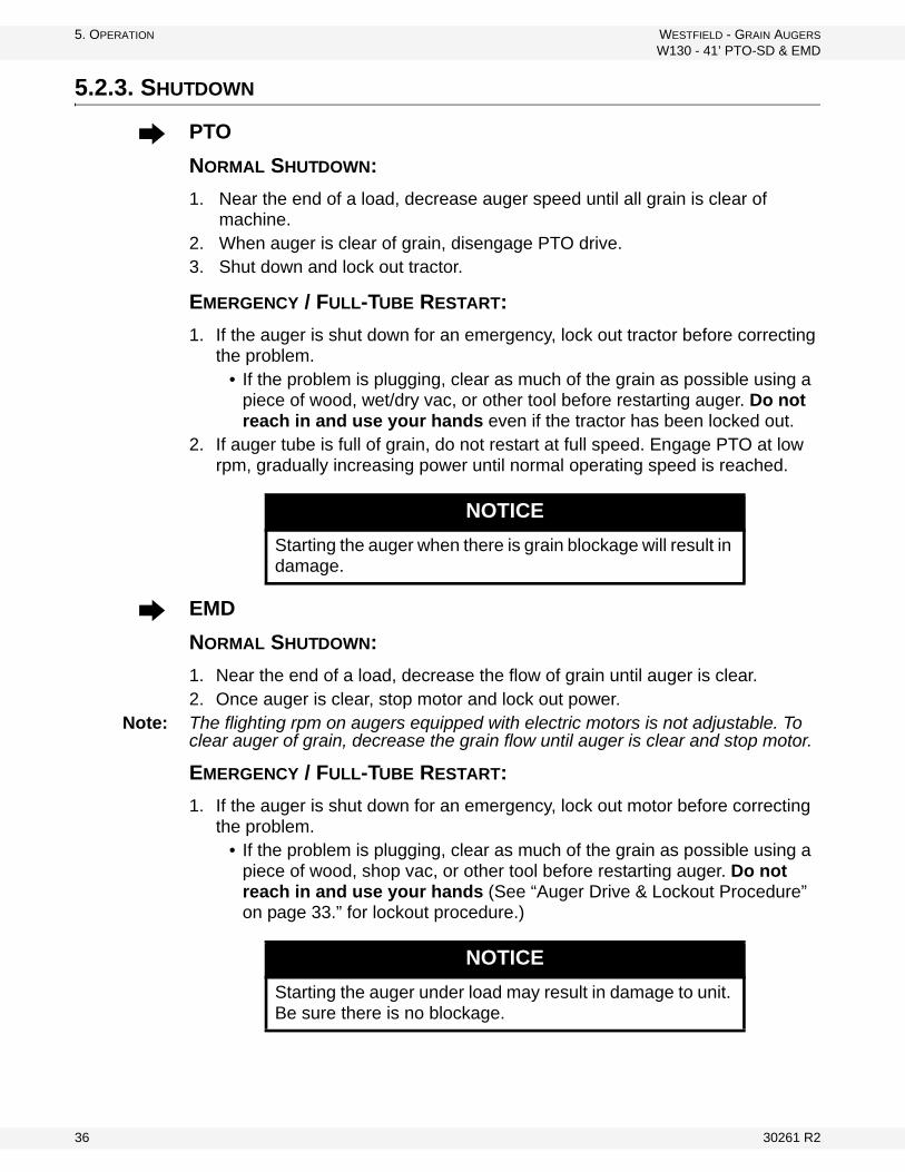
5. OPERATION WESTFIELD - GRAIN AUGERS
W130 - 41’ PTO-SD & EMD
5.2.3. SHUTDOWN
PTO
NORMAL SHUTDOWN:
1. Near the end of a load, decrease auger speed until all grain is clear of machine.
2. When auger is clear of grain, disengage PTO drive.3. Shut down and lock out tractor.
EMERGENCY / FULL-TUBE RESTART:
1. If the auger is shut down for an emergency, lock out tractor before correcting the problem.
• If the problem is plugging, clear as much of the grain as possible using a piece of wood, wet/dry vac, or other tool before restarting auger. Do not reach in and use your hands even if the tractor has been locked out.
2. If auger tube is full of grain, do not restart at full speed. Engage PTO at low rpm, gradually increasing power until normal operating speed is reached.
EMD
NORMAL SHUTDOWN:
1. Near the end of a load, decrease the flow of grain until auger is clear.2. Once auger is clear, stop motor and lock out power.
Note: The flighting rpm on augers equipped with electric motors is not adjustable. To clear auger of grain, decrease the grain flow until auger is clear and stop motor.
EMERGENCY / FULL-TUBE RESTART:
1. If the auger is shut down for an emergency, lock out motor before correcting the problem.
• If the problem is plugging, clear as much of the grain as possible using a piece of wood, shop vac, or other tool before restarting auger. Do not reach in and use your hands (See “Auger Drive & Lockout Procedure” on page 33.” for lockout procedure.)
NOTICE
Starting the auger when there is grain blockage will result in damage.
NOTICE
Starting the auger under load may result in damage to unit. Be sure there is no blockage.
36 30261 R2

WESTFIELD - GRAIN AUGERS 5. OPERATION
W130 - 41’ PTO-SD & EMD
5.2.4. LOWERING & COMPLETION
After operation:
1. Clean entire work area.2. Remove all supports and chocks.3. Move auger out of working position and lower fully (see shaded box that
follows for lowering procedure).4. Move auger to the next work area or to a storage area and then clean out.
5. Clean out auger.a. Shut off tractor engine and lock out power.
b. Manually clean out grain with a piece of wood, vacuum cleaner, or other tool. Do not use hands.
6. Prepare for transport and placement or storage (see appropriate chapters for more information).
LOWERING
1. For PTO drives: disconnect driveline from tractor before lowering.2. Ensure area beneath auger is clear.3. Turn winch counterclockwise to lower (no clicking sound when lowering).4. After lowering, turn handle clockwise until you hear 2 clicks to lock brake.
• Use a firm grip on handle. Do not release unless ratchet pawl is fully engaged.
• The winch is designed for manual operation only.• When lowering, never continue to turn handle counterclockwise if the
cable does not keep moving out under load. This will disengage the brake mechanism and create an unsafe condition. If this happens, winch in slack cable and correct problem.
Do not leave auger in raised position when not in use. Auger could drop rapidly due to a cable break. High winds may also upset auger.
30261 R2 37

5. OPERATION WESTFIELD - GRAIN AUGERS
W130 - 41’ PTO-SD & EMD
38 30261 R2

WESTFIELD - GRAIN AUGERS 6. MAINTENANCE & STORAGE
W130 - 41’ PTO-SD & EMD
6. Maintenance & Storage
Proper maintenance habits on the 130-41’ auger mean a longer life for the machine and a more efficient and safer operation.
6.1. GENERAL MAINTENANCE PROCEDURES
Please follow the guidelines below.
Warning: Before continuing, ensure you have read and understand the relevant information in the safety section. Safety information is provided to help prevent serious injury, death, or property damage.
Area Maintenance Frequency
GeneralWhile auger is in use, observe the “Pre-Operational Check-list” on page 33.
Daily
GeneralCheck all operating, lifting, and transport components. Replace damaged or worn parts before using auger.
For replacement instructions, see Assembly Section.Regularly
Lift CableCheck and replace if frayed or damaged. Make sure cable clamps are secure.
Periodically
Wheel Hubs Repack with lithium-based grease. Every 2–3 years
Tire PressureCheck with a pressure gauge. Pressure should be main-tained according to tire sidewall recommendation.
Monthly, or if it seems low
PTO DrivelineLubricate both universal joints.
After every 8 hours of opera-tion
Lubricate the center portion of the driveline (grease fitting is beneath shield) on a yearly basis.
Yearly
Upper chain drive
Fill enclosed upper drive housing to plug level with grease.130: 3400 g (120 oz)For continuous use in extreme cold, semi-fluid arctic grease or heavy oil may be used
Yearly
Drive Chain Adjust-ment
Maintain 1/4” - 1/2” (0.64 cm - 1.27 cm) chain deflection.To adjust, loosen bolts on top bearing in the upper drive housing, adjust hcian to proper tension, and re-tighten bolts
Regularly
Intake Bushing Lubricate. Daily
Gearbox
Maintain oil level at half full (center of cross shaft) with EP90 lube oil.
Gearbox should be level when checking or refillingDo not overfill
Oil must be added to gearbox before operat-ing, and then reg-ularly as needed
Drive Belt
Check and replace if frayed or damaged.Ensure tension is correct under load (correct tension is the lowest at which the belts will not slip under peak load condi-tions)
Frequently
30261 R2 39
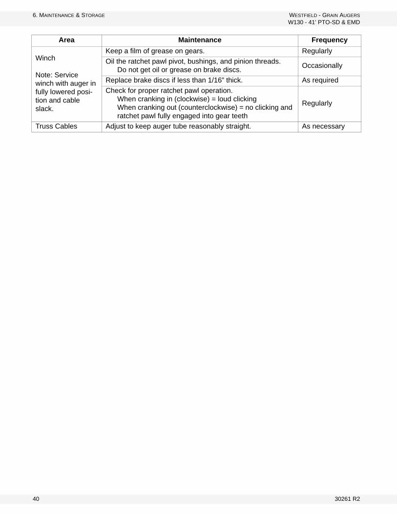
6. MAINTENANCE & STORAGE WESTFIELD - GRAIN AUGERS
W130 - 41’ PTO-SD & EMD
Winch
Note: Service winch with auger in fully lowered posi-tion and cable slack.
Keep a film of grease on gears. Regularly
Oil the ratchet pawl pivot, bushings, and pinion threads. Do not get oil or grease on brake discs.
Occasionally
Replace brake discs if less than 1/16” thick. As required
Check for proper ratchet pawl operation.When cranking in (clockwise) = loud clickingWhen cranking out (counterclockwise) = no clicking and ratchet pawl fully engaged into gear teeth
Regularly
Truss Cables Adjust to keep auger tube reasonably straight. As necessary
Area Maintenance Frequency
40 30261 R2
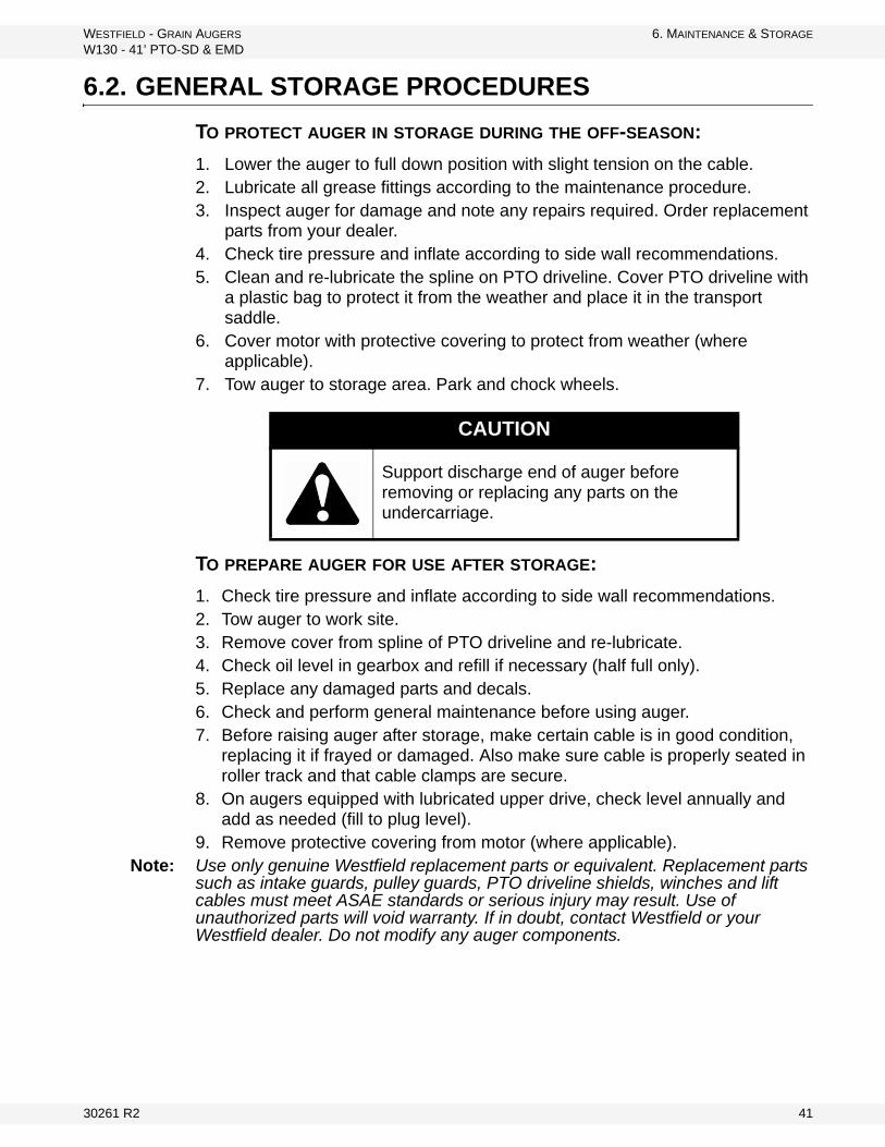
WESTFIELD - GRAIN AUGERS 6. MAINTENANCE & STORAGE
W130 - 41’ PTO-SD & EMD
6.2. GENERAL STORAGE PROCEDURES
TO PROTECT AUGER IN STORAGE DURING THE OFF-SEASON:
1. Lower the auger to full down position with slight tension on the cable.2. Lubricate all grease fittings according to the maintenance procedure.3. Inspect auger for damage and note any repairs required. Order replacement
parts from your dealer.4. Check tire pressure and inflate according to side wall recommendations.5. Clean and re-lubricate the spline on PTO driveline. Cover PTO driveline with
a plastic bag to protect it from the weather and place it in the transport saddle.
6. Cover motor with protective covering to protect from weather (where applicable).
7. Tow auger to storage area. Park and chock wheels.
TO PREPARE AUGER FOR USE AFTER STORAGE:
1. Check tire pressure and inflate according to side wall recommendations.2. Tow auger to work site.3. Remove cover from spline of PTO driveline and re-lubricate.4. Check oil level in gearbox and refill if necessary (half full only).5. Replace any damaged parts and decals.6. Check and perform general maintenance before using auger.7. Before raising auger after storage, make certain cable is in good condition,
replacing it if frayed or damaged. Also make sure cable is properly seated in roller track and that cable clamps are secure.
8. On augers equipped with lubricated upper drive, check level annually and add as needed (fill to plug level).
9. Remove protective covering from motor (where applicable).Note: Use only genuine Westfield replacement parts or equivalent. Replacement parts
such as intake guards, pulley guards, PTO driveline shields, winches and lift cables must meet ASAE standards or serious injury may result. Use of unauthorized parts will void warranty. If in doubt, contact Westfield or your Westfield dealer. Do not modify any auger components.
CAUTION
Support discharge end of auger before removing or replacing any parts on the undercarriage.
30261 R2 41

6. MAINTENANCE & STORAGE WESTFIELD - GRAIN AUGERS
W130 - 41’ PTO-SD & EMD
42 30261 R2

WESTFIELD - GRAIN AUGERS 7. TROUBLESHOOTING
W130 - 41’ PTO-SD & EMD
7. Troubleshooting
Problem Possible Cause Remedy
Excessive noise or vibra-tion.
*Remember to follow proper break-in proce-dures—auger may run rough until tube is pol-ished. If noise is extreme from outset or con-tinuous after several loads of grade are fed, continue with troubleshoot-ing below
Chatter from wooden bearings.
Spray penetrating lubricant between shaft and bearing surface. Bearings will break in over time.*If replacement of a bearing becomes neces-sary, split bearings are available to avoid having to slide all bearings off driveshaft.
Truss cables incorrectly adjusted.
Support end of auger and adjust cables so auger is flat or curves slightly upwards.
Flighting peeled back due to plugging.
Inspect spout end of auger for flight condition. Remove and replace flight sections as neces-sary.
Top drive inadequately lubri-cated.
Fill to appropriate level with grease.Top drive is not designed to be filled with oil.
Bent flighting sections.
Support auger and remove all flight sections. Check for straightness of flight stubs by rolling across flat concrete section. Straighten stub or replace as necessary. Take care not to bend flighting when reinstalling.
Obstruction in tube.Visually inspect for cloth or trash wrapped around flighting, or buildup of gum from oily crops such as flax or canola.
Drive belts jumping off pulleys.
Motor misaligned.Ensure drive and driven pulleys are correctly aligned.
Belts mismatched.Check manual for correct belt sizes and only replace in pairs.
Belt tension inadequate. Maintain correct tension as per manual.
Using a lower horsepower motor than recommended.
See manual for recommended motor sizes.
Shear bolts fail repeatedly.
Incorrect shear bolt type.Replace with correct part number. Westfield shear bolts are specifically designed to provide correct driveline protection.
Shear bolt hole worn out-of-round.
Frequent use of the incorrect shear bolt size can wear the mounting hole creating a “scissor effect,” which will require replacement of the affected parts.
Corn spreaders in bin unable to keep up with auger output.
Slow down auger or remove corn spreaders.
Flighting peeled back as a result of plugging.
Occurs when bin has overfilled, or corn spread-ers restrict end of discharge. Inspect flighting at discharge end of auger. If necessary, replace flighting.
Driveline failure (bearing, gear-box, etc.).
See maintenance section.
30261 R2 43
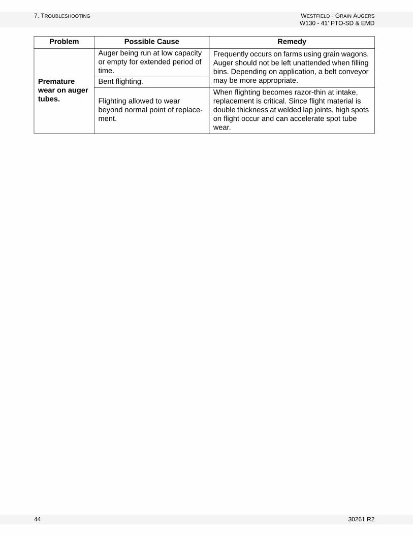
7. TROUBLESHOOTING WESTFIELD - GRAIN AUGERS
W130 - 41’ PTO-SD & EMD
Premature wear on auger tubes.
Auger being run at low capacity or empty for extended period of time.
Frequently occurs on farms using grain wagons. Auger should not be left unattended when filling bins. Depending on application, a belt conveyor may be more appropriate.Bent flighting.
Flighting allowed to wear beyond normal point of replace-ment.
When flighting becomes razor-thin at intake, replacement is critical. Since flight material is double thickness at welded lap joints, high spots on flight occur and can accelerate spot tube wear.
Problem Possible Cause Remedy
44 30261 R2

WARRANTYWestfield Industries Ltd. warrants products of its manufacture against defects in materials or workmanship under normal and reasonable use for a period of one year after date of delivery to the original purchaser.
Our obligation under this warranty is limited to repairing, replacing, or refunding defective part or parts which shall be returned to a distributor or a dealer of our Company, or to our factory, with transportation charges prepaid. This warranty does not obligate Westfield Industries Ltd. to bear the cost of labor in replacing defective parts. Any defects must be reported to the Company before the end of the one year period.
This warranty shall not apply to equipment which has been altered, improperly assembled, improperly maintained, or improperly repaired so as to adversely affect its performance. Westfield Industries Ltd. makes no express warranty of any character with respect to parts not of its manufacture.
The foregoing is in lieu of all other warranties, expressed or implied, including any warranties that extend beyond the description of the product, and the IMPLIED WARRANTY of MERCHANTABILITY is expressly excluded.
WESTFIELD INDUSTRIES LTD.
ROSENORT, MANITOBA
CANADA
R0G 1W0

Westfield Industries is a Division of Ag Growth Industries Partnership
Part of the Ag Growth International Inc. Group
P.O. Box 39
Rosenort, Manitoba, Canada R0G 1W0
Phone: (866) 467-7207 (Canada & USA)
Fax: (866) 768-4852
website: www.grainaugers.com
email: [email protected]
© Ag Growth Industries Partnership 2013
Printed in Canada
GRAIN AUGERSW130 - 51’/61’/71’ PTO-SD
ASSEMBLY & OPERATION MANUAL
Part Number: 30262 R0
Revised: Feb/10
Read this manual before using product. Failure to follow instructions and safety precautions can result in serious injury, death, or property damage. Keep manual for future reference.

This product has been designed and constructed according to general engineering standardsa. Other local regulations may apply and must be followed by the operator. We strongly recommend that all personnel associated with this equipment be trained in the correct operational and safety procedures required for this product. Periodic reviews of this manual with all employees should be standard practice. For your convenience, we include this sign-off sheet so you can record your periodic reviews.
a. Standards include organizations such as the American Society of Agricultural and Biological Engineers, American National Standards Institute, Canadian Standards Association, International Organization for Standardization, and/or others.
Date Employee Signature Employer Signature

TABLE OF CONTENTS
WESTFIELD - GRAIN AUGERS W130 - 51’/61’/71’ PTO-SD
1. Introduction .......................................................................................................................... 5
2. Safety First............................................................................................................................ 72.1. General Safety ......................................................................................................... 82.2. Assembly Safety....................................................................................................... 92.3. Transport & Placement Safety ................................................................................. 92.4. PTO Safety............................................................................................................. 102.5. Hydraulic Safety ..................................................................................................... 102.6. Operational Safety.................................................................................................. 102.7. Maintenance Safety................................................................................................ 122.8. Safety Decal Locations........................................................................................... 12
2.8.1. Decal Installation ...................................................................................... 122.8.2. Decal Locations ........................................................................................ 12
3. Assembly ............................................................................................................................ 153.1. Tubes & Flighting ................................................................................................... 153.2. Track Shoe & Track Stop ....................................................................................... 163.3. Intake Hitch ............................................................................................................ 183.4. Multi-Stage Driveshaft ............................................................................................ 183.5. Shaft Drive Gearbox............................................................................................... 193.6. Driveshaft Shield .................................................................................................... 203.7. Discharge Spout..................................................................................................... 213.8. Truss ...................................................................................................................... 213.9. Transport Undercarriage ........................................................................................ 243.10. Lift Cylinders & Cable........................................................................................... 273.11. Hydraulic Hose Attachment.................................................................................. 293.12. PTO Driveline ....................................................................................................... 303.13. Upper Housing Lubrication................................................................................... 303.14. Plastic Manual Holder .......................................................................................... 30
4. Transport & Placement ...................................................................................................... 314.1. Transport Procedure .............................................................................................. 314.2. Placement Procedure............................................................................................. 32
5. Operation ............................................................................................................................ 355.1. Pre-Operational Checklist ...................................................................................... 355.2. Auger Drive & Lockout Procedure.......................................................................... 355.3. Operating Procedure .............................................................................................. 36
5.3.1. Start-Up & Break-In .................................................................................. 365.3.2. Operating With A Full Load ...................................................................... 365.3.3. Shutdown.................................................................................................. 375.3.4. Lowering & Completion ............................................................................ 38
6. Maintenance & Storage...................................................................................................... 396.1. General Maintenance Procedures.......................................................................... 396.2. General Storage Procedures.................................................................................. 40
30262 R0 3

TABLE OF CONTENTS
WESTFIELD - GRAIN AUGERS
W130 - 51’/61’/71’ PTO-SD
7. Troubleshooting ................................................................................................................. 41
Warranty.................................................................................................................................. 43
4 30262 R0

WESTFIELD - GRAIN AUGERS 1. INTRODUCTION
W130 - 51’/61’/71’ PTO-SD
1. IntroductionCongratulations. As the new owner of a grain auger, you will be working with equipment designed to complement and improve your farming operation. Before using this auger, please read this manual and all safety labels and familiarize yourself with the various features of the machine and the necessary precautions for efficient and safe operation.
In addition, anyone using this auger is required to comply with all safety precau-tions in this manual and in safety labels attached to the auger. A sign-off form is supplied on the inside front cover to record your safety reviews.
Thank you.
Serial Number:
Serial number is found on the right at the top of the lower tube.
30262 R0 5

1. INTRODUCTION WESTFIELD - GRAIN AUGERS
W130 - 51’/61’/71’ PTO-SD
6 30262 R0

WESTFIELD - GRAIN AUGERS 2. SAFETY FIRST
W130 - 51’/61’/71’ PTO-SD
2. Safety FirstThe Safety Alert symbol to the left identifies important safety messages on the product and in the manual. When you see this symbol, be alert to the possibil-ity of personal injury or death. Follow the instructions in the safety messages. Why is SAFETY important to you?
Three big reasons:
• Accidents disable and kill.• Accidents cost.• Accidents can be avoided.
SIGNAL WORDS
Note the use of the signal words DANGER, WARNING, CAUTION, and NOTICE with the safety messages. The appropriate signal word for each message has been selected using the definitions below as a guideline.
The Safety Alert symbol means ATTENTION, BE ALERT!, YOUR SAFETY IS INVOLVED.
DANGER
Indicates an imminently hazardous situation that, if not avoided, will result in serious injury or death.
WARNING
Indicates a hazardous situation that, if not avoided, could result in serious injury or death.
CAUTION
Indicates a hazardous situation that, if not avoided, may result in minor or moderate injury.
NOTICE
Indicates a potentially hazardous situation that, if not avoided, may result in property damage.
30262 R0 7

2. SAFETY FIRST WESTFIELD - GRAIN AUGERS
2.1. GENERAL SAFETY W130 - 51’/61’/71’ PTO-SD
2.1. GENERAL SAFETY
Important: The general safety section includes instructions that apply to all safety practices. Any instructions specific to a certain safety practice (e.g., assembly safety), can be found in the appropriate section. Always read the complete instructional sections and not just these safety summaries before doing anything with the equipment.
YOU are responsible for the SAFE use and maintenance of your equipment. YOU must ensure that you and anyone else who is going to work around the equipment understands all procedures and related SAFETY information contained in this manual.
Remember, YOU are the key to safety. Good safety practices not only protect you, but also the people around you. Make these practices a working part of your safety program.
• It is the equipment owner and the operator's responsibility to read and under-stand ALL safety instructions, safety decals, and manuals and follow them before assembling, operating, or maintaining the equipment. All accidents can be avoided.
• Equipment owners must give instructions and review the information initially and anually with all personnel before allowing them to operate this product. Untrained users/operators expose themselves and bystanders to possible serious injury or death.
• Use this equipment for its intended purposes only.• Do not modify the equipment in any way. Unauthorized modification may
impair the function and/or safety, and could affect the life of the equipment. Any modification to the equipment voids the warranty.
• Do not allow children, spectators, or bystanders within the work area.• Have a first-aid kit available for use should the need arise, and know how to
use it.• Provide a fire extinguisher for use in case of an accident. Store in a highly vis-
ible place.• Wear appropriate protective gear. This list includes, but
is not limited to:• a hard hat• gloves• protective shoes with slip-resistant soles• protective goggles• hearing protection
• For Powered Equipment: before servicing, adjusting, or repairing powered equipment, unplug, place all controls in neutral or off position, stop the engine or motor, remove ignition key or lock out power source, and wait for all mov-ing parts to stop.
8 30262 R0
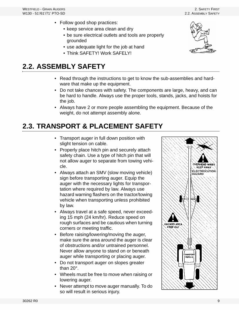
WESTFIELD - GRAIN AUGERS 2. SAFETY FIRST
W130 - 51’/61’/71’ PTO-SD 2.2. ASSEMBLY SAFETY
• Follow good shop practices:• keep service area clean and dry• be sure electrical outlets and tools are properly
grounded• use adequate light for the job at hand• Think SAFETY! Work SAFELY!
2.2. ASSEMBLY SAFETY
• Read through the instructions to get to know the sub-assemblies and hard-ware that make up the equipment.
• Do not take chances with safety. The components are large, heavy, and can be hard to handle. Always use the proper tools, stands, jacks, and hoists for the job.
• Always have 2 or more people assembling the equipment. Because of the weight, do not attempt assembly alone.
2.3. TRANSPORT & PLACEMENT SAFETY
• Transport auger in full down position with slight tension on cable.
• Properly place hitch pin and securely attach safety chain. Use a type of hitch pin that will not allow auger to separate from towing vehi-cle.
• Always attach an SMV (slow moving vehicle) sign before transporting auger. Equip the auger with the necessary lights for transpor-tation where required by law. Always use hazard warning flashers on the tractor/towing vehicle when transporting unless prohibited by law.
• Always travel at a safe speed, never exceed-ing 15 mph (24 km/hr). Reduce speed on rough surfaces and be cautious when turning corners or meeting traffic.
• Before raising/lowering/moving the auger, make sure the area around the auger is clear of obstructions and/or untrained personnel. Never allow anyone to stand on or beneath auger while transporting or placing auger.
• Do not transport auger on slopes greater than 20°.
• Wheels must be free to move when raising or lowering auger.
• Never attempt to move auger manually. To do so will result in serious injury.
ELECTROCUTION HAZARD
30262 R0 9
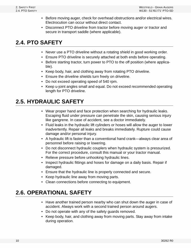
2. SAFETY FIRST WESTFIELD - GRAIN AUGERS
2.4. PTO SAFETY W130 - 51’/61’/71’ PTO-SD
• Before moving auger, check for overhead obstructions and/or electrical wires. Electrocution can occur without direct contact.
• Disconnect PTO driveline from tractor before moving auger or tractor and secure in transport saddle (where applicable).
2.4. PTO SAFETY
• Never use a PTO driveline without a rotating shield in good working order.• Ensure PTO driveline is securely attached at both ends before operating.• Before starting tractor, turn power to PTO to the off position (where applica-
ble).• Keep body, hair, and clothing away from rotating PTO driveline.• Ensure the driveline shields turn freely on driveline.• Do not exceed operating speed of 540 rpm.• Keep u-joint angles small and equal. Do not exceed recommended operating
length for PTO driveline.
2.5. HYDRAULIC SAFETY
• Wear proper hand and face protection when searching for hydraulic leaks. Escaping fluid under pressure can penetrate the skin, causing serious injury like gangrene. In case of accident, see a doctor immediately.
• Fluid leaks in the hydraulic lift cylinders or hoses will allow the auger to lower inadvertently. Repair all leaks and breaks immediately. Rupture could cause damage and/or personal injury.
• A hydraulic lift is faster than a conventional hand crank—always clear area of personnel before raising or lowering.
• Do not disconnect hydraulic couplers when hydraulic system is pressurized. For the correct procedure, consult this manual or your tractor manual.
• Relieve pressure before unhooking hydraulic lines.• Inspect hydraulic fittings and hoses for damage on a daily basis. Repair if
damaged.• Ensure that the hydraulic line is properly connected and secure.• Keep hydraulic line away from moving parts.• Clean connections before connecting to equipment.
2.6. OPERATIONAL SAFETY
• Have another trained person nearby who can shut down the auger in case of accident. Always work with a second trained person around augers.
• Do not operate with any of the safety guards removed.• Keep body, hair, and clothing away from moving parts. Stay away from intake
during operation.
10 30262 R0

WESTFIELD - GRAIN AUGERS 2. SAFETY FIRST
W130 - 51’/61’/71’ PTO-SD 2.6. OPERATIONAL SAFETY
• Inspect lift cable before using auger. Replace if frayed or damaged. Make sure it is seated properly in the cable sheaves and that cable clamps are secure.
• Operate auger on level ground free of debris. If ground is uneven, anchor the auger to prevent tipping or upending.
• Augers are not insulated. Keep away from electrical lines. Electrocution can occur without direct contact.
• Support the discharge end and/or anchor the intake end before operating to prevent upending.
• Do not use auger as a hoist.• Empty auger before raising or lowering.• Lower auger at completion of operation or when not in use. Auger could drop
rapidly in case of cable break or hydraulic failure (where applicable).
Figure 2.1
30262 R0 11

2. SAFETY FIRST WESTFIELD - GRAIN AUGERS
2.7. MAINTENANCE SAFETY W130 - 51’/61’/71’ PTO-SD
2.7. MAINTENANCE SAFETY
• Shut down and lock out all power before attempting maintenance of any kind. If applicable, disconnect PTO driveline from tractor or hydraulic hoses on units with hydraulic drive hoppers.
• After maintenance is complete, replace and secure all safety guards and safety devices, and if applicable, service doors and cleanout covers.
• Support auger tube before attempting maintenance on the undercarriage assembly. Auger should be in full down position for maintenance.
• Use only genuine Westfield replacement parts or equivalent. Replacement parts such as intake guards, pulley guards, PTO driveline shields, winches, and lift cables must meet ASABE standards or serious injury may result. Use of unauthorized parts will void warranty. If in doubt, contact Westfield or your Westfield dealer.
• Do not modify any auger components without authorization from Westfield. Modification can be dangerous and result in serious injuries.
2.8. SAFETY DECAL LOCATIONS
• Keep safety decals clean and legible at all times.• Replace safety decals that are missing or have become illegible. See decal
location figures below.• Replaced parts must display the same decal(s) as the original part.• Safety decals are available from your distributor, dealer, or factory.
2.8.1. DECAL INSTALLATION
1. Decal area must be clean and dry, with a temperature above 10°C (50°F).2. Decide on the exact position before you remove the backing paper.3. Align the decal over the specified area and carefully press the small portion
with the exposed sticky backing in place.4. Slowly peel back the remaining paper and carefully smooth the remaining
portion of the decal in place.5. Small air pockets can be pierced with a pin and smoothed out using the sign
backing paper.
2.8.2. DECAL LOCATIONS
Replicas of the safety decals that are attached to the equipment are shown below. Good safety requires that you familiarize yourself with the various safety decals and the areas or particular functions that the decals apply to as well as the safety precautions that must be taken to avoid serious, injury, death, or damage.
* Westfield reserves the right to update safety decals without notice. Safety decals may not be exactly as shown.
12 30262 R0
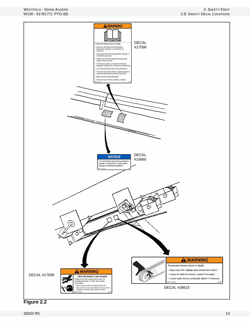
WESTFIELD - GRAIN AUGERS 2. SAFETY FIRST
W130 - 51’/61’/71’ PTO-SD 2.8. SAFETY DECAL LOCATIONS
Figure 2.2
DECAL #17096
DECAL #19960
DECAL #28615
DECAL #17698
30262 R0 13
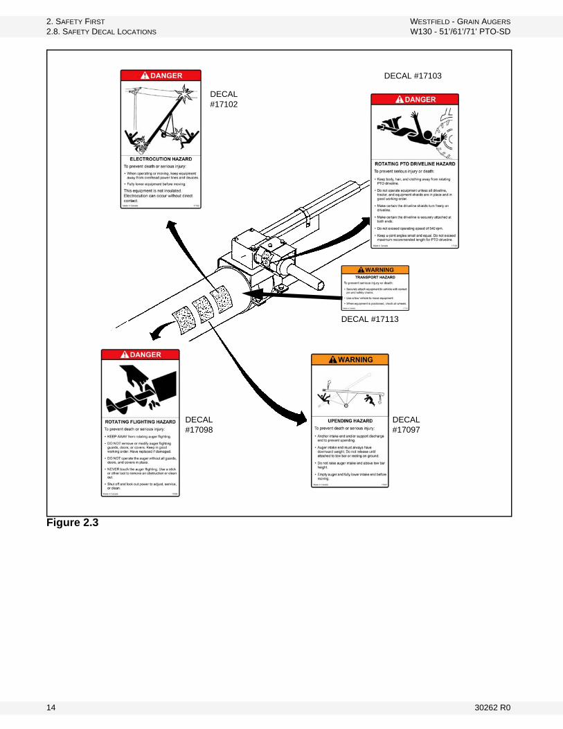
2. SAFETY FIRST WESTFIELD - GRAIN AUGERS
2.8. SAFETY DECAL LOCATIONS W130 - 51’/61’/71’ PTO-SD
Figure 2.3
DECAL #17102
DECAL #17103
DECAL #17098
DECAL #17097
DECAL #17113
14 30262 R0
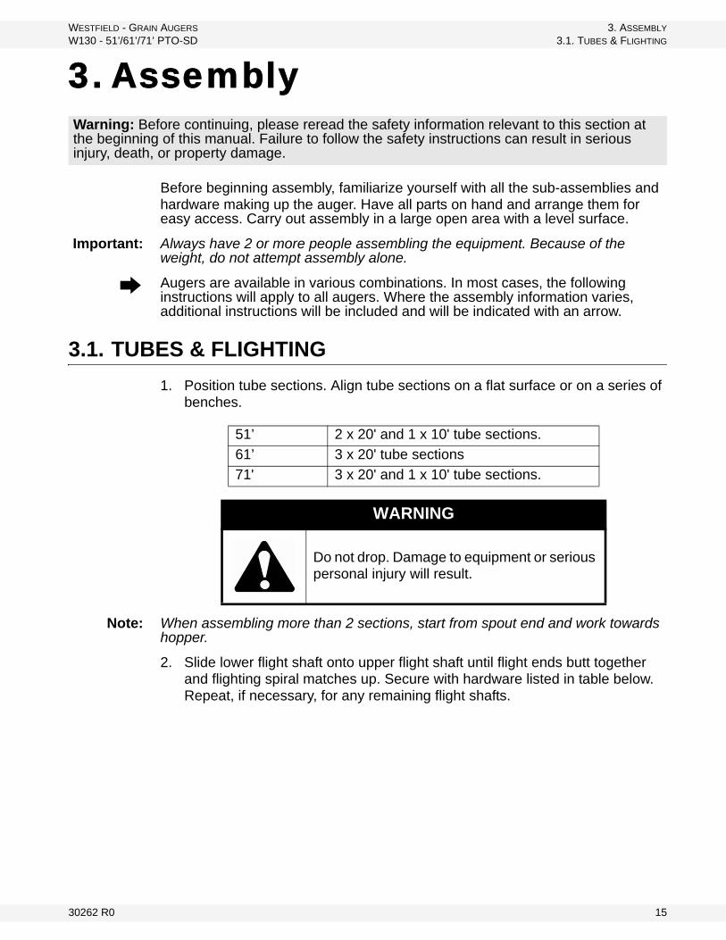
WESTFIELD - GRAIN AUGERS 3. ASSEMBLY
W130 - 51’/61’/71’ PTO-SD 3.1. TUBES & FLIGHTING
3. Assembly
Before beginning assembly, familiarize yourself with all the sub-assemblies and hardware making up the auger. Have all parts on hand and arrange them for easy access. Carry out assembly in a large open area with a level surface.
Important: Always have 2 or more people assembling the equipment. Because of the weight, do not attempt assembly alone.
Augers are available in various combinations. In most cases, the following instructions will apply to all augers. Where the assembly information varies, additional instructions will be included and will be indicated with an arrow.
3.1. TUBES & FLIGHTING
1. Position tube sections. Align tube sections on a flat surface or on a series of benches.
Note: When assembling more than 2 sections, start from spout end and work towards hopper.
2. Slide lower flight shaft onto upper flight shaft until flight ends butt together and flighting spiral matches up. Secure with hardware listed in table below. Repeat, if necessary, for any remaining flight shafts.
Warning: Before continuing, please reread the safety information relevant to this section at the beginning of this manual. Failure to follow the safety instructions can result in serious injury, death, or property damage.
51’ 2 x 20' and 1 x 10' tube sections.
61’ 3 x 20' tube sections
71' 3 x 20' and 1 x 10' tube sections.
WARNING
Do not drop. Damage to equipment or serious personal injury will result.
30262 R0 15

3. ASSEMBLY WESTFIELD - GRAIN AUGERS
3.2. TRACK SHOE & TRACK STOP W130 - 51’/61’/71’ PTO-SD
3. Slide tube sections together and secure.
Make sure to align upper and lower track ends and then tighten bolts. Secure with hardware in table below.
Track ends must align to allow track shoe to smoothly slide over track joint. Misalignment may cause jamming.
Figure 3.2
3.2. TRACK SHOE & TRACK STOP
1. Slide the roller track shoe onto track with cable attach rod towards auger intake (Figure 3.3)
2. Attach the angle track stop as shown in Figure 3.4 with four 7/16” x 1-1/4” bolts and locknuts (see below for correct location, or refer to Figure 3.11).
Details for fasteners
For Flighting Amt For Tubes Amt
5/8” x 4-1/2” GR 8 bolts and locknuts
27/16” x 1-1/4” bolts and lock-nuts
12
Figure 3.1
Important:
16 30262 R0
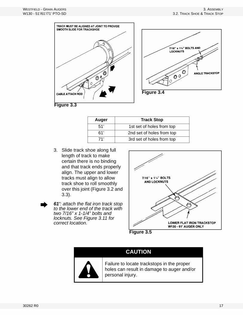
WESTFIELD - GRAIN AUGERS 3. ASSEMBLY
W130 - 51’/61’/71’ PTO-SD 3.2. TRACK SHOE & TRACK STOP
3. Slide track shoe along full length of track to make certain there is no binding and that track ends properly align. The upper and lower tracks must align to allow track shoe to roll smoothly over this joint (Figure 3.2 and 3.3).
61': attach the flat iron track stop to the lower end of the track with two 7/16” x 1-1/4” bolts and locknuts. See Figure 3.11 for correct location.
Auger Track Stop
51’ 1st set of holes from top
61’ 2nd set of holes from top
71’ 3rd set of holes from top
CAUTION
Failure to locate trackstops in the proper holes can result in damage to auger and/or personal injury.
Figure 3.4
Figure 3.3
Figure 3.5
30262 R0 17
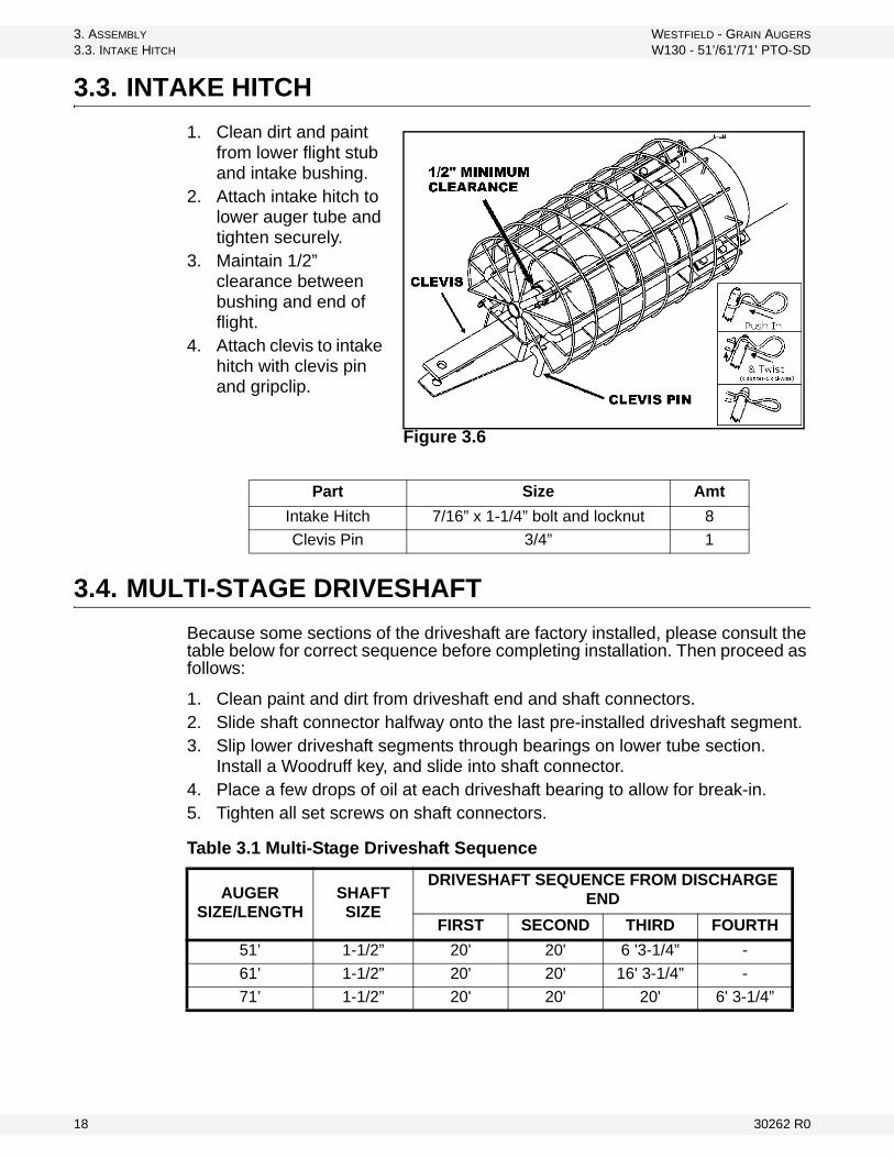
3. ASSEMBLY WESTFIELD - GRAIN AUGERS
3.3. INTAKE HITCH W130 - 51’/61’/71’ PTO-SD
3.3. INTAKE HITCH
1. Clean dirt and paint from lower flight stub and intake bushing.
2. Attach intake hitch to lower auger tube and tighten securely.
3. Maintain 1/2” clearance between bushing and end of flight.
4. Attach clevis to intake hitch with clevis pin and gripclip.
3.4. MULTI-STAGE DRIVESHAFT
Because some sections of the driveshaft are factory installed, please consult the table below for correct sequence before completing installation. Then proceed as follows:
1. Clean paint and dirt from driveshaft end and shaft connectors.2. Slide shaft connector halfway onto the last pre-installed driveshaft segment.3. Slip lower driveshaft segments through bearings on lower tube section.
Install a Woodruff key, and slide into shaft connector.4. Place a few drops of oil at each driveshaft bearing to allow for break-in.5. Tighten all set screws on shaft connectors.
Part Size Amt
Intake Hitch 7/16” x 1-1/4” bolt and locknut 8
Clevis Pin 3/4” 1
Figure 3.6
Table 3.1 Multi-Stage Driveshaft Sequence
AUGERSIZE/LENGTH
SHAFTSIZE
DRIVESHAFT SEQUENCE FROM DISCHARGE END
FIRST SECOND THIRD FOURTH
51’ 1-1/2” 20' 20' 6 '3-1/4” -
61’ 1-1/2” 20' 20' 16' 3-1/4” -
71’ 1-1/2” 20' 20' 20' 6' 3-1/4”
18 30262 R0

WESTFIELD - GRAIN AUGERS 3. ASSEMBLY
W130 - 51’/61’/71’ PTO-SD 3.5. SHAFT DRIVE GEARBOX
3.5. SHAFT DRIVE GEARBOX
These augers are equipped with chain couplers pre-installed on gearbox.
1. Remove chain and secure half the chain coupler to driveshaft using a 3/8” x 1-3/4” long square key.
2. Place gearbox assembly on auger tube leaving a minimum 1/8” clearance between chain connectors.
3. Re-install chain and adjust sprocket clearance to approximately 1/16”. Tighten set screw (Figure 3.7).
Important: Add EP90 lube oil the gearbox before operating auger. Failure to do so will void warranty. Do not overfill. Fill half full only. It is easier to fill oil into gear box when in flat position.
Figure 3.7
30262 R0 19
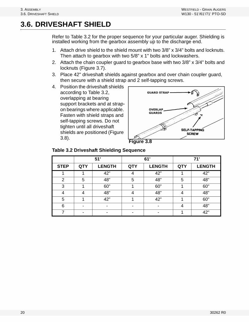
3. ASSEMBLY WESTFIELD - GRAIN AUGERS
3.6. DRIVESHAFT SHIELD W130 - 51’/61’/71’ PTO-SD
3.6. DRIVESHAFT SHIELD
Refer to Table 3.2 for the proper sequence for your particular auger. Shielding is installed working from the gearbox assembly up to the discharge end.
1. Attach drive shield to the shield mount with two 3/8” x 3/4” bolts and locknuts. Then attach to gearbox with two 5/8” x 1" bolts and lockwashers.
2. Attach the chain coupler guard to gearbox base with two 3/8” x 3/4” bolts and locknuts (Figure 3.7).
3. Place 42" driveshaft shields against gearbox and over chain coupler guard, then secure with a shield strap and 2 self-tapping screws.
4. Position the driveshaft shields according to Table 3.2, overlapping at bearing support brackets and at strap-on bearings where applicable. Fasten with shield straps and self-tapping screws. Do not tighten until all driveshaft shields are positioned (Figure 3.8).
Table 3.2 Driveshaft Shielding Sequence
51’ 61’ 71’
STEP QTY LENGTH QTY LENGTH QTY LENGTH
1 1 42” 4 42” 1 42"
2 5 48” 5 48” 5 48"
3 1 60” 1 60” 1 60"
4 4 48” 4 48” 4 48"
5 1 42” 1 42” 1 60"
6 - - - - 4 48"
7 - - - - 1 42"
Figure 3.8
20 30262 R0
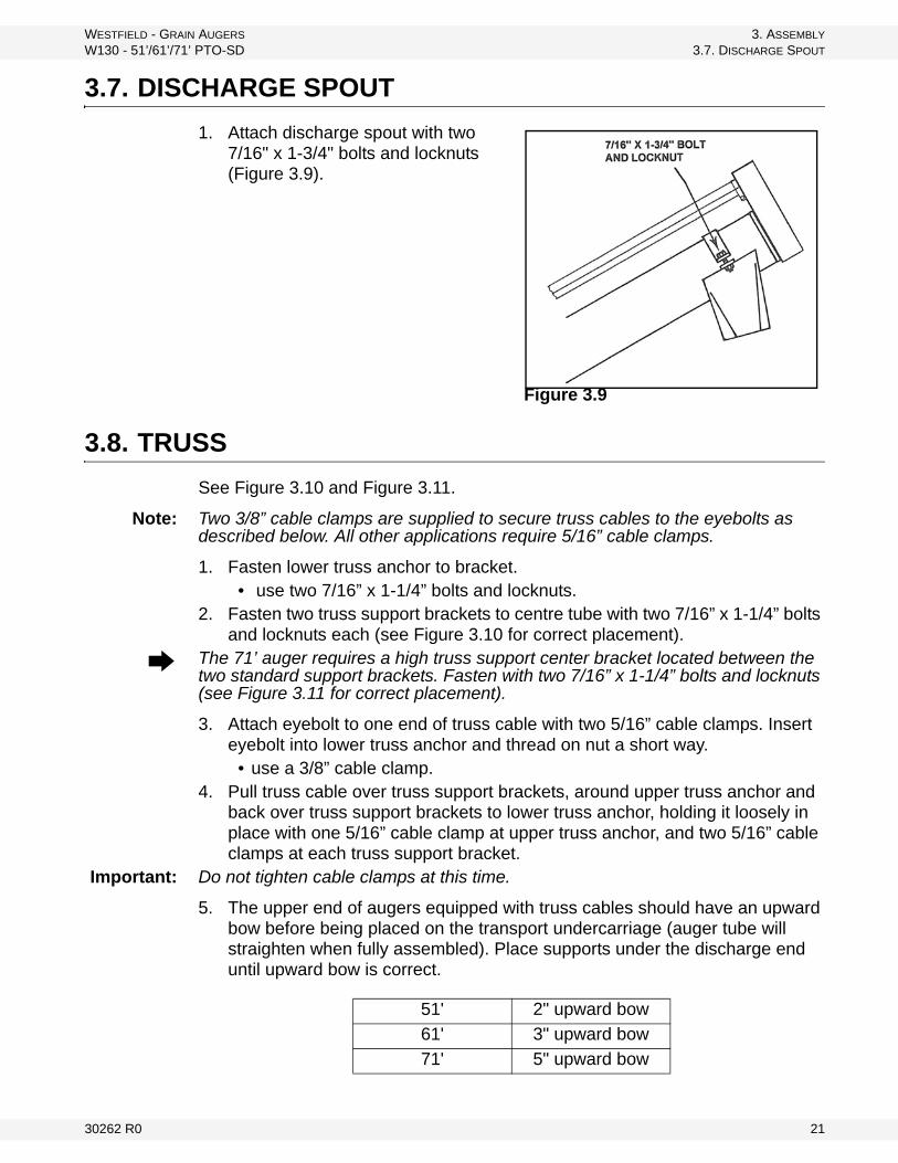
WESTFIELD - GRAIN AUGERS 3. ASSEMBLY
W130 - 51’/61’/71’ PTO-SD 3.7. DISCHARGE SPOUT
3.7. DISCHARGE SPOUT
1. Attach discharge spout with two 7/16" x 1-3/4" bolts and locknuts (Figure 3.9).
3.8. TRUSS
See Figure 3.10 and Figure 3.11.
Note: Two 3/8” cable clamps are supplied to secure truss cables to the eyebolts as described below. All other applications require 5/16” cable clamps.
1. Fasten lower truss anchor to bracket.• use two 7/16” x 1-1/4” bolts and locknuts.
2. Fasten two truss support brackets to centre tube with two 7/16” x 1-1/4” bolts and locknuts each (see Figure 3.10 for correct placement).
The 71’ auger requires a high truss support center bracket located between the two standard support brackets. Fasten with two 7/16” x 1-1/4” bolts and locknuts (see Figure 3.11 for correct placement).
3. Attach eyebolt to one end of truss cable with two 5/16” cable clamps. Insert eyebolt into lower truss anchor and thread on nut a short way.
• use a 3/8” cable clamp.4. Pull truss cable over truss support brackets, around upper truss anchor and
back over truss support brackets to lower truss anchor, holding it loosely in place with one 5/16” cable clamp at upper truss anchor, and two 5/16” cable clamps at each truss support bracket.
Important: Do not tighten cable clamps at this time.
5. The upper end of augers equipped with truss cables should have an upward bow before being placed on the transport undercarriage (auger tube will straighten when fully assembled). Place supports under the discharge end until upward bow is correct.
Figure 3.9
51' 2" upward bow
61' 3" upward bow
71' 5" upward bow
30262 R0 21
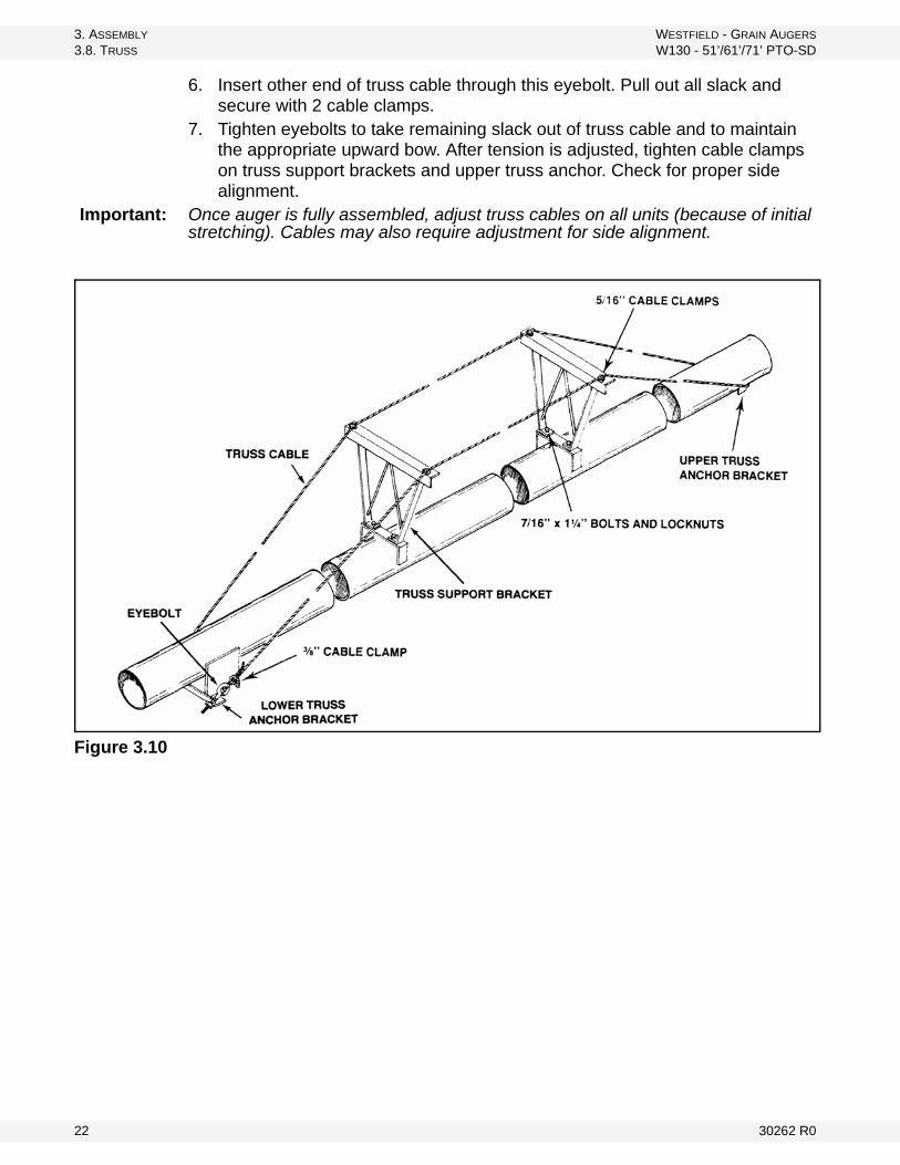
3. ASSEMBLY WESTFIELD - GRAIN AUGERS
3.8. TRUSS W130 - 51’/61’/71’ PTO-SD
6. Insert other end of truss cable through this eyebolt. Pull out all slack and secure with 2 cable clamps.
7. Tighten eyebolts to take remaining slack out of truss cable and to maintain the appropriate upward bow. After tension is adjusted, tighten cable clamps on truss support brackets and upper truss anchor. Check for proper side alignment.
Important: Once auger is fully assembled, adjust truss cables on all units (because of initial stretching). Cables may also require adjustment for side alignment.
Figure 3.10
22 30262 R0
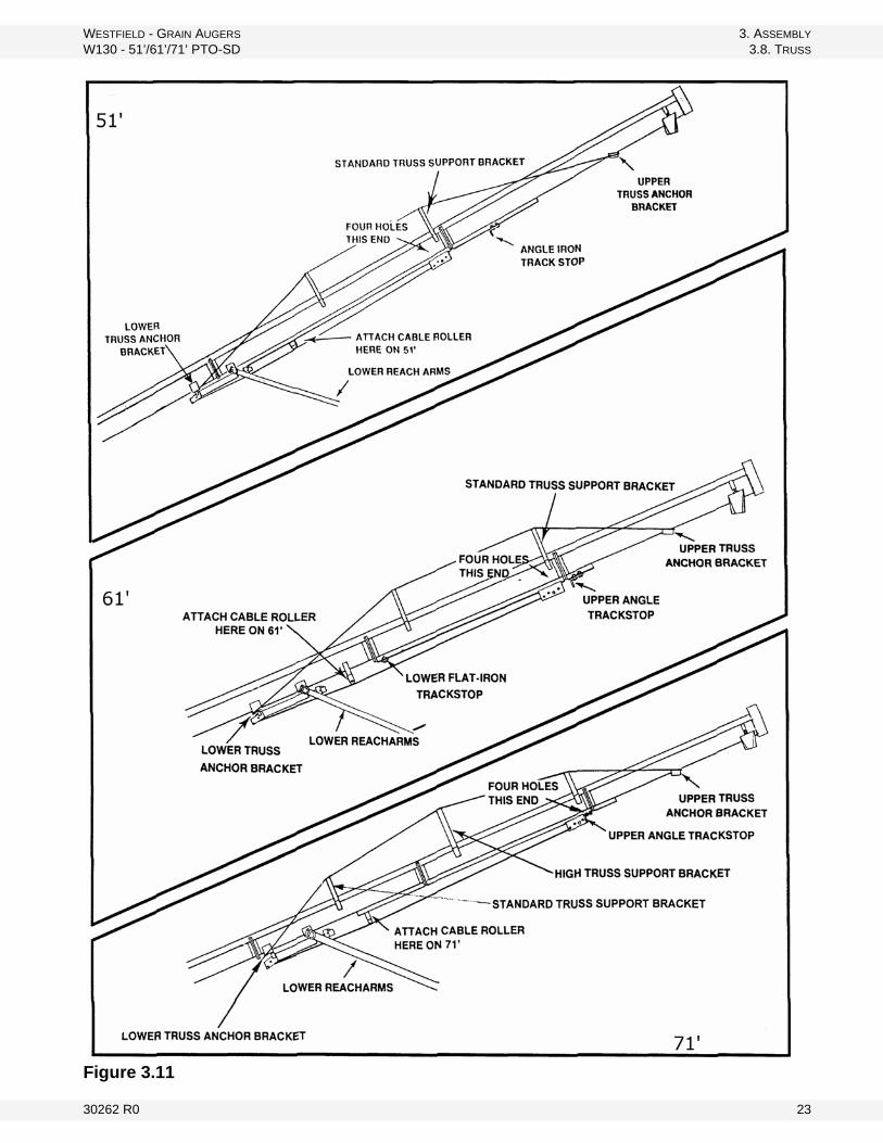
WESTFIELD - GRAIN AUGERS 3. ASSEMBLY
W130 - 51’/61’/71’ PTO-SD 3.8. TRUSS
Figure 3.11
30262 R0 23
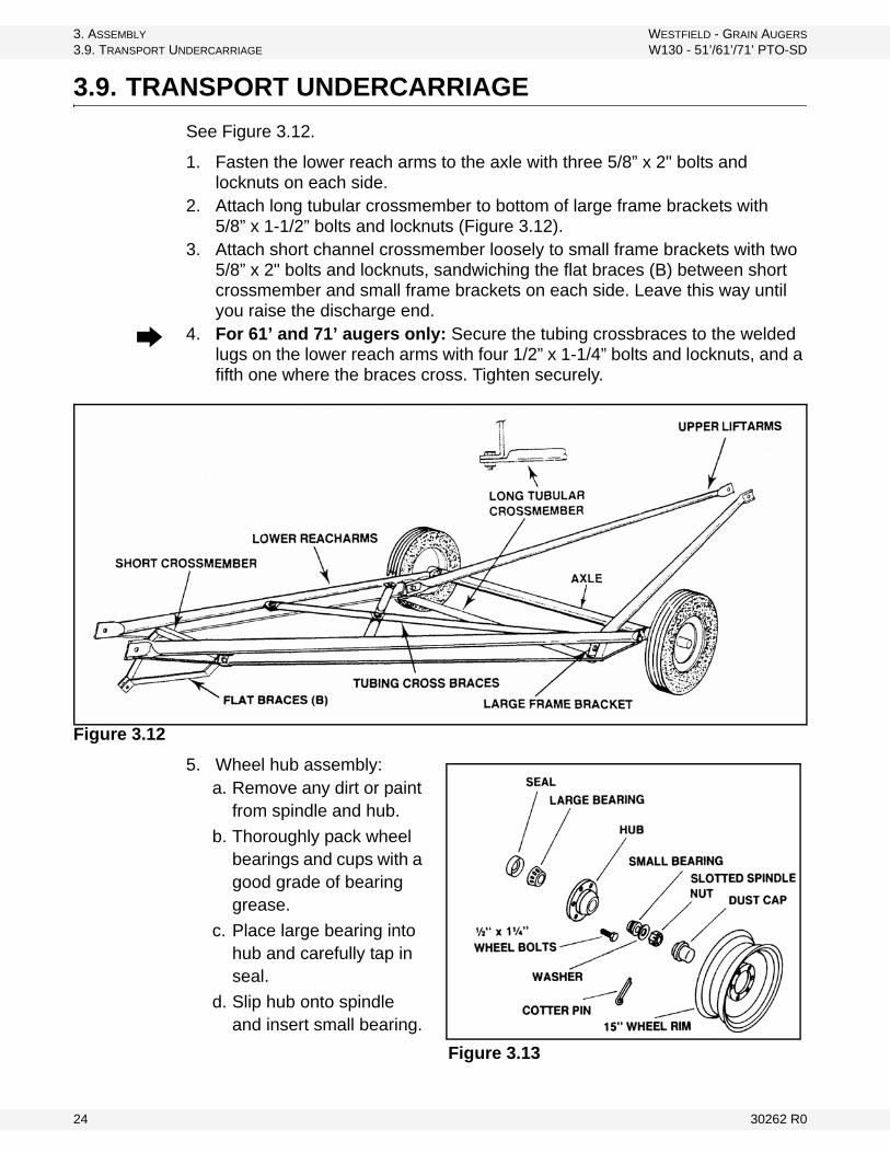
3. ASSEMBLY WESTFIELD - GRAIN AUGERS
3.9. TRANSPORT UNDERCARRIAGE W130 - 51’/61’/71’ PTO-SD
3.9. TRANSPORT UNDERCARRIAGE
See Figure 3.12.
1. Fasten the lower reach arms to the axle with three 5/8” x 2" bolts and locknuts on each side.
2. Attach long tubular crossmember to bottom of large frame brackets with 5/8” x 1-1/2” bolts and locknuts (Figure 3.12).
3. Attach short channel crossmember loosely to small frame brackets with two 5/8” x 2" bolts and locknuts, sandwiching the flat braces (B) between short crossmember and small frame brackets on each side. Leave this way until you raise the discharge end.
4. For 61’ and 71’ augers only: Secure the tubing crossbraces to the welded lugs on the lower reach arms with four 1/2” x 1-1/4” bolts and locknuts, and a fifth one where the braces cross. Tighten securely.
Figure 3.12
5. Wheel hub assembly:a. Remove any dirt or paint
from spindle and hub.
b. Thoroughly pack wheel bearings and cups with a good grade of bearing grease.
c. Place large bearing into hub and carefully tap in seal.
d. Slip hub onto spindle and insert small bearing.
Figure 3.13
24 30262 R0
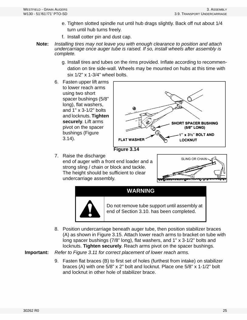
WESTFIELD - GRAIN AUGERS 3. ASSEMBLY
W130 - 51’/61’/71’ PTO-SD 3.9. TRANSPORT UNDERCARRIAGE
e. Tighten slotted spindle nut until hub drags slightly. Back off nut about 1/4 turn until hub turns freely.
f. Install cotter pin and dust cap.
Note: Installing tires may not leave you with enough clearance to position and attach undercarriage once auger tube is raised. If so, install wheels after assembly is complete.
g. Install tires and tubes on the rims provided. Inflate according to recommen-dation on tire side-wall. Wheels may be mounted on hubs at this time with six 1/2” x 1-3/4” wheel bolts.
6. Fasten upper lift arms to lower reach arms using two short spacer bushings (5/8” long), flat washers, and 1" x 3-1/2” bolts and locknuts. Tighten securely. Lift arms pivot on the spacer bushings (Figure 3.14).
7. Raise the discharge end of auger with a front end loader and a strong sling / chain or block and tackle. The height should be sufficient to clear undercarriage assembly.
8. Position undercarriage beneath auger tube, then position stabilizer braces (A) as shown in Figure 3.15. Attach lower reach arms to bracket on tube with long spacer bushings (7/8” long), flat washers, and 1" x 3-1/2” bolts and locknuts. Tighten securely. Reach arms pivot on the spacer bushings.
Important: Refer to Figure 3.11 for correct placement of lower reach arms.
9. Fasten flat braces (B) to first set of holes (furthest from intake) on stabilizer braces (A) with one 5/8” x 2" bolt and locknut. Place one 5/8” x 1-1/2” bolt and locknut in other hole of stabilizer brace.
WARNING
Do not remove tube support until assembly at end of Section 3.10. has been completed.
Figure 3.14
30262 R0 25
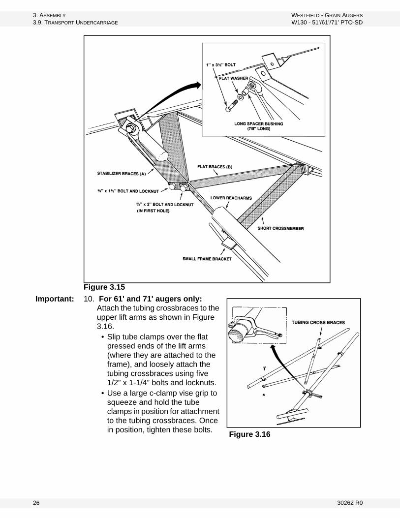
3. ASSEMBLY WESTFIELD - GRAIN AUGERS
3.9. TRANSPORT UNDERCARRIAGE W130 - 51’/61’/71’ PTO-SD
Figure 3.15
Important: 10. For 61' and 71' augers only: Attach the tubing crossbraces to the upper lift arms as shown in Figure 3.16.
• Slip tube clamps over the flat pressed ends of the lift arms (where they are attached to the frame), and loosely attach the tubing crossbraces using five 1/2” x 1-1/4” bolts and locknuts.
• Use a large c-clamp vise grip to squeeze and hold the tube clamps in position for attachment to the tubing crossbraces. Once in position, tighten these bolts.
Figure 3.16
26 30262 R0
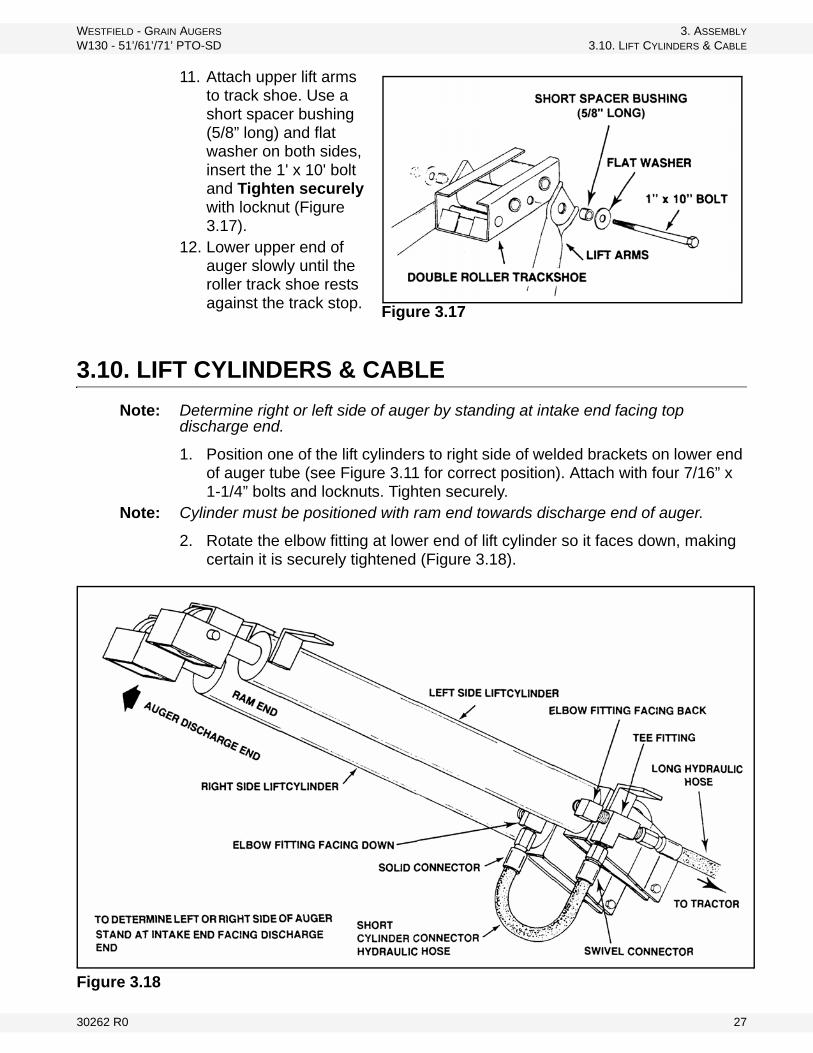
WESTFIELD - GRAIN AUGERS 3. ASSEMBLY
W130 - 51’/61’/71’ PTO-SD 3.10. LIFT CYLINDERS & CABLE
11. Attach upper lift arms to track shoe. Use a short spacer bushing (5/8” long) and flat washer on both sides, insert the 1' x 10' bolt and Tighten securely with locknut (Figure 3.17).
12. Lower upper end of auger slowly until the roller track shoe rests against the track stop.
3.10. LIFT CYLINDERS & CABLE
Note: Determine right or left side of auger by standing at intake end facing top discharge end.
1. Position one of the lift cylinders to right side of welded brackets on lower end of auger tube (see Figure 3.11 for correct position). Attach with four 7/16” x 1-1/4” bolts and locknuts. Tighten securely.
Note: Cylinder must be positioned with ram end towards discharge end of auger.
2. Rotate the elbow fitting at lower end of lift cylinder so it faces down, making certain it is securely tightened (Figure 3.18).
Figure 3.18
Figure 3.17
30262 R0 27
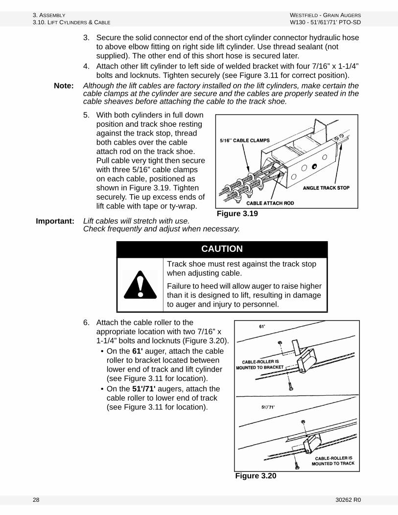
3. ASSEMBLY WESTFIELD - GRAIN AUGERS
3.10. LIFT CYLINDERS & CABLE W130 - 51’/61’/71’ PTO-SD
3. Secure the solid connector end of the short cylinder connector hydraulic hose to above elbow fitting on right side lift cylinder. Use thread sealant (not supplied). The other end of this short hose is secured later.
4. Attach other lift cylinder to left side of welded bracket with four 7/16” x 1-1/4” bolts and locknuts. Tighten securely (see Figure 3.11 for correct position).
Note: Although the lift cables are factory installed on the lift cylinders, make certain the cable clamps at the cylinder are secure and the cables are properly seated in the cable sheaves before attaching the cable to the track shoe.
5. With both cylinders in full down position and track shoe resting against the track stop, thread both cables over the cable attach rod on the track shoe. Pull cable very tight then secure with three 5/16” cable clamps on each cable, positioned as shown in Figure 3.19. Tighten securely. Tie up excess ends of lift cable with tape or ty-wrap.
Lift cables will stretch with use. Check frequently and adjust when necessary.
6. Attach the cable roller to the appropriate location with two 7/16” x 1-1/4” bolts and locknuts (Figure 3.20).
• On the 61' auger, attach the cable roller to bracket located between lower end of track and lift cylinder (see Figure 3.11 for location).
• On the 51'/71' augers, attach the cable roller to lower end of track (see Figure 3.11 for location).
CAUTION
Track shoe must rest against the track stop when adjusting cable.
Failure to heed will allow auger to raise higher than it is designed to lift, resulting in damage to auger and injury to personnel.
Figure 3.19 Important:
Figure 3.20
28 30262 R0
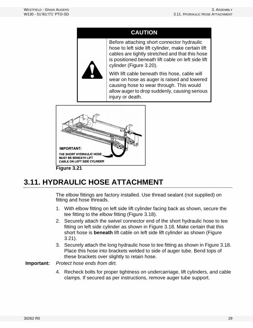
WESTFIELD - GRAIN AUGERS 3. ASSEMBLY
W130 - 51’/61’/71’ PTO-SD 3.11. HYDRAULIC HOSE ATTACHMENT
Figure 3.21
3.11. HYDRAULIC HOSE ATTACHMENT
The elbow fittings are factory installed. Use thread sealant (not supplied) on fitting and hose threads.
1. With elbow fitting on left side lift cylinder facing back as shown, secure the tee fitting to the elbow fitting (Figure 3.18).
2. Securely attach the swivel connector end of the short hydraulic hose to tee fitting on left side cylinder as shown in Figure 3.18. Make certain that this short hose is beneath lift cable on left side lift cylinder as shown (Figure 3.21).
3. Securely attach the long hydraulic hose to tee fitting as shown in Figure 3.18. Place this hose into brackets welded to side of auger tube. Bend tops of these brackets over slightly to retain hose.
Important: Protect hose ends from dirt.
4. Recheck bolts for proper tightness on undercarriage, lift cylinders, and cable clamps. If secured as per instructions, remove auger tube support.
CAUTION
Before attaching short connector hydraulic hose to left side lift cylinder, make certain lift cables are tightly stretched and that this hose is positioned beneath lift cable on left side lift cylinder (Figure 3.20).
With lift cable beneath this hose, cable will wear on hose as auger is raised and lowered causing hose to wear through. This would allow auger to drop suddenly, causing serious injury or death.
30262 R0 29
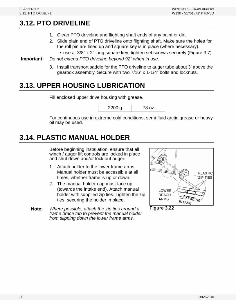
3. ASSEMBLY WESTFIELD - GRAIN AUGERS
3.12. PTO DRIVELINE W130 - 51’/61’/71’ PTO-SD
3.12. PTO DRIVELINE
1. Clean PTO driveline and flighting shaft ends of any paint or dirt.2. Slide plain end of PTO driveline onto flighting shaft. Make sure the holes for
the roll pin are lined up and square key is in place (where necessary). • use a 3/8” x 2" long square key; tighten set screws securely (Figure 3.7).
Important: Do not extend PTO driveline beyond 92” when in use.
3. Install transport saddle for the PTO driveline to auger tube about 3’ above the gearbox assembly. Secure with two 7/16” x 1-1/4” bolts and locknuts.
3.13. UPPER HOUSING LUBRICATION
Fill enclosed upper drive housing with grease.
For continuous use in extreme cold conditions, semi-fluid arctic grease or heavy oil may be used.
3.14. PLASTIC MANUAL HOLDER
Before beginning installation, ensure that all winch / auger lift controls are locked in place and shut down and/or lock out auger.
1. Attach holder to the lower frame arms. Manual holder must be accessible at all times, whether frame is up or down.
2. The manual holder cap must face up (towards the intake end). Attach manual holder with supplied zip ties. Tighten the zip ties, securing the holder in place.
Where possible, attach the zip ties around a frame brace tab to prevent the manual holder from slipping down the lower frame arms.
2200 g 78 oz
LOWER REACH ARMS
PLASTIC ZIP TIES
CAP FACING INTAKE
Figure 3.22 Note:
30 30262 R0
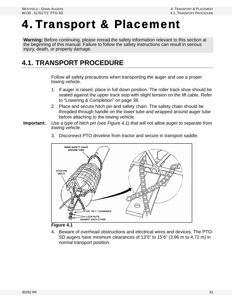
WESTFIELD - GRAIN AUGERS 4. TRANSPORT & PLACEMENT
W130 - 51’/61’/71’ PTO-SD 4.1. TRANSPORT PROCEDURE
4. Transport & Placement
4.1. TRANSPORT PROCEDURE
Follow all safety precautions when transporting the auger and use a proper towing vehicle.
1. If auger is raised, place in full down position. The roller track shoe should be seated against the upper track stop with slight tension on the lift cable. Refer to “Lowering & Completion” on page 38.
2. Place and secure hitch pin and safety chain. The safety chain should be threaded through handle on the lower tube and wrapped around auger tube before attaching to the towing vehicle.
Important: Use a type of hitch pin (see Figure 4.1) that will not allow auger to separate from towing vehicle.
3. Disconnect PTO driveline from tractor and secure in transport saddle.
Figure 4.1
4. Beware of overhead obstructions and electrical wires and devices. The PTO-SD augers have minimum clearances of 13’0” to 15’6” (3.96 m to 4.72 m) in normal transport position.
Warning: Before continuing, please reread the safety information relevant to this section at the beginning of this manual. Failure to follow the safety instructions can result in serious injury, death, or property damage.
30262 R0 31
4. TRANSPORT & PLACEMENT WESTFIELD - GRAIN AUGERS
4.2. PLACEMENT PROCEDURE W130 - 51’/61’/71’ PTO-SD
5. Refer to “Transport & Placement Safety” on page 11 for important safety information before towing.
4.2. PLACEMENT PROCEDURE
1. Ensure towing hitch is in place and secure.Important: Use a type of hitch pin (Figure 4.1) that will not allow auger to separate from
towing vehicle.
2. Before raising or positioning auger, make sure that entire area in line of travel, both on the ground and overhead, is clear on any obstructions or electrical wires.
3. Ensure auger is on reasonably level ground when raising, lowering, or positioning.
Important: Make sure cable is properly seated in the cable sheaves on the lift cylinder and that cable clamps are secure.
Important: Wheels must be free to move when raising or lowering auger.
Note: The PTO driveline is non-separable. Remove from tractor and secure in transport saddle on auger before moving tractor away from auger.
Note: Because of the varied types of tractor hydraulic systems, the quick-connect coupler is to be supplied by the owner. Please consult your tractor manual or your dealer for the proper coupler.
CAUTION
If auger wheels are partially or fully buried in snow or grain, failure to clear area around the wheels before moving may cause damage to the auger or result in serious injury.
WARNING
If auger wheels are partially or fully buried in snow or grain, failure to clear the area around the wheels before moving may cause damage to the auger or result in serious injury.
WARNING
Never attempt to increase height of auger by positioning wheels on lumber, blocks, or by any other means. To do so will result in damage to equipment and/or personal injury.
32 30262 R0

WESTFIELD - GRAIN AUGERS 4. TRANSPORT & PLACEMENT
W130 - 51’/61’/71’ PTO-SD 4.2. PLACEMENT PROCEDURE
4. Before connecting the hydraulic hose, ensure that the quick connect couplers on auger and tractor are clean and free of dirt by wiping with a cloth.
5. After connecting hydraulic hose, visually check it for leaks, binding, flattening, kinks or wear.
Important: The 130 auger is elevated with two 4 inch single-acting hydraulic cylinders and cables. The following table lists the PSI required to raise specific auger sizes as determined by Westfield testing.
These tests were conducted using a hydraulic pressure gauge (4000 PSI maximum rating) and are solely intended to be used as a guide. The PSI require-ments for a specific auger may vary slightly. Should your auger require a signifi-cantly higher PSI to raise, contact either your dealer or Westfield.
6. Approximate quantity of hydraulic fluid required to raise auger is as follows:
NOTICE
Dirt in the hydraulic system can damage the cylinder o-rings causing leakage and the possible failure of the system.
Table 4.1
AUGER PSI KPa
130-51' 1400 9653
130-61' 1600 11032
130-71' 1800 12411
CAUTION
Do not disconnect hydraulic coupler when system is pressurized.
W130-51' 12.4 litres
W130-61' 15 litres
W130-71' 18 litres
30262 R0 33
4. TRANSPORT & PLACEMENT WESTFIELD - GRAIN AUGERS
4.2. PLACEMENT PROCEDURE W130 - 51’/61’/71’ PTO-SD
7. To raise auger check that the valve on hose to lift cylinders is open, raise the auger to desired height, and close hose valve.
8. Move the auger into working position slowly. Do not unhitch and attempt to move auger by hand.
9. Once auger is in position, chock wheels on both sides and apply the park brake on the tractor (or chock its wheels as well) to prevent movement during operation.
Important: When releasing auger from the towing vehicle, test the intake end for downward weight. Do not raise the intake end above drawbar height. When the intake end is elevated too high with auger in raised position, the balance of weight quickly transfers to the discharge end, causing it to upend. Ensure proper anchoring / support.
10. When operating auger in the raised position, rest the discharge end lightly on the bin roof, or tie to bin to prevent wind from toppling auger. When operating the auger in a freestanding position, anchor the intake end.
11. Anchor and/or support auger during operation.• When lower half of auger empties of grain, the weight balance transfers
to upper end of auger, which can cause upending.12. See “Completion / Clean Up” on page 42 for correct lowering procedure.
WARNING
If hose valve remains open, a loss of hydraulic pressure within the tractor system will allow the auger to lower inadvertently, damaging equipment and/or causing personal injury.
Do not disconnect coupler under pressure. Relieve pressure and then disconnect.
Fluid leaks in the hydraulic cylinders or hoses will allow auger to lower inadvertently. Repair all leaks and breaks immediately.
CAUTION
Do not use auger as a hoist to raise any object regardless of weight. This will create an unsafe condition and will void warranty.
34 30262 R0
WESTFIELD - GRAIN AUGERS 5. OPERATION
W130 - 51’/61’/71’ PTO-SD 5.1. PRE-OPERATIONAL CHECKLIST
5. Operation
5.1. PRE-OPERATIONAL CHECKLIST
Before operating auger each time, the operator must confirm the following:
• All fasteners are secure as per assembly instructions.• PTO driveline is connected and secure.• PTO driveline shield rotates freely.• Lift cable is not frayed or damaged.• Lift cable is properly seated in cable sheaves.• Cable clamps are secure.• Tube alignment is reasonably straight.• Auger wheels are chocked, and if necessary, tractor wheels are chocked
or the parking brake has been engaged.• Intake area and discharge spout are free of obstructions.• Proper maintenance has been performed.
5.2. AUGER DRIVE & LOCKOUT PROCEDURE
Warning: Before continuing, please reread the safety information relevant to this section at the beginning of this manual. Failure to follow the safety instructions can result in serious injury, death, or property damage.
Drive Type
Before Operation Lockout
PTO Driveline
Before starting, ensure:
• PTO driveline is securely attached to the tractor and gearbox
• tractor park brake in engaged and/or wheels are chocked
• you are not exceeding the maximum operating length of 92” (2337 mm) of the PTO driveline or maximum angle of 15°
• PTO drive on the tractor is in the off position
Shut off tractor’s engine and remove key from tractor.
• If removing key is impossible, remove PTO driveline from trac-tor.
30262 R0 35

5. OPERATION WESTFIELD - GRAIN AUGERS
5.3. OPERATING PROCEDURE W130 - 51’/61’/71’ PTO-SD
5.3. OPERATING PROCEDURE
5.3.1. START-UP & BREAK-IN
1. Properly place auger and complete the pre-operational checklist at the beginning of this chapter. If everything is satisfactory, prepare for a 30-minute operation at half speed.
2. Correctly position portable grain hopper secure it to the auger with both straps (where applicable).
Important: Anchoring and/or support auger during operation. When lower half of auger empties of grain, the weight balance transfers to the upper end of auger, which can cause upending.
3. Start tractor and engage PTO driveline, then feed grain to auger. If auger functions normally, check at varying speeds for a period of 30 minutes.
Important: When starting auger for the first time, be prepared for an emergency shutdown in case of excessive vibration or noise. Note that auger may run rough until tube is polished.
4. Upon completion of initial run, shutdown auger (see section below for more information on shutting down your auger).
5. Lock out tractor and conduct a complete inspection of auger following the checklist at the beginning of this chapter.
After the initial start-up and inspection, the auger should be shut down and inspected at least three more times during the first 10 hours of operation.
Keep operation of empty auger to a minimum, as this results in excessive wear.
Once auger is broken in, the checklist should be a part of the daily routine before operating auger.
5.3.2. OPERATING WITH A FULL LOAD
1. When operating the auger, always work with a second person in a position to monitor the operation and initiate a shutdown in case of emergency.
2. Monitor the auger during operation for abnormal noises or vibrations.3. Shut off all power before making adjustments, servicing, or clearing the
machine.
CAUTION
Do not start auger until area is clear of all unauthorized personnel.
Do not exceed 540 rpm on the PTO.
36 30262 R0
WESTFIELD - GRAIN AUGERS 5. OPERATION
W130 - 51’/61’/71’ PTO-SD 5.3. OPERATING PROCEDURE
5.3.3. SHUTDOWN
NORMAL SHUTDOWN:
1. Near the end of a load, decrease auger speed until all grain is clear of machine.
2. When auger is clear of grain, disengage PTO drive.3. Shut down and lock out tractor.
EMERGENCY / FULL-TUBE RESTART:
1. If the auger is shut down for an emergency, lock out tractor before correcting the problem.
DANGER
Rotating Flighting Hazard!
To prevent death or serious injury:• Keep away from rotating auger flighting.• Do not remove or modify auger flighting
guards, doors, or covers. Keep in good working order. Have replaced if damaged.
• Do not operate the auger without all guards, doors, and covers in place.
• Never touch the auger flighting. Use a stick or other tool to remove an obstruc-tion or clean out.
• Shut off and lock out power to adjust, service, or clean.
USE OF GRAIN SPREADERS: Many grain spreaders cannot handle the large capacity of some augers. Some augers plug, causing damage to the flighting and other drive components. This type of damage is not covered by warranty. Hints on how to avoid this...
• Get a larger spreader, if available.• Remove the spreader.• Make sure spreader is turned on.• Center auger spout on spreader.• Do not lower auger spout into spreader.• Suspend the spreader from bin ceiling leaving extra room for excess
grain to flow over the spreader.
BIN LEVEL INDICATORS: These augers are fast and bins fill up quickly. A full bin will cause auger to plug, which can damage the flighting and other drive components. Installing quality grain-level indicators on your bins will allow you to monitor bin filling and help prevent damage to your auger.
30262 R0 37
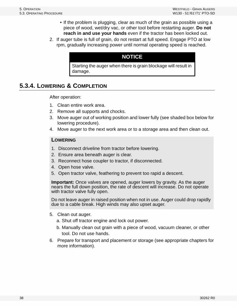
5. OPERATION WESTFIELD - GRAIN AUGERS
5.3. OPERATING PROCEDURE W130 - 51’/61’/71’ PTO-SD
• If the problem is plugging, clear as much of the grain as possible using a piece of wood, wet/dry vac, or other tool before restarting auger. Do not reach in and use your hands even if the tractor has been locked out.
2. If auger tube is full of grain, do not restart at full speed. Engage PTO at low rpm, gradually increasing power until normal operating speed is reached.
5.3.4. LOWERING & COMPLETION
After operation:
1. Clean entire work area.2. Remove all supports and chocks.3. Move auger out of working position and lower fully (see shaded box below for
lowering procedure).4. Move auger to the next work area or to a storage area and then clean out.
5. Clean out auger.a. Shut off tractor engine and lock out power.
b. Manually clean out grain with a piece of wood, vacuum cleaner, or other tool. Do not use hands.
6. Prepare for transport and placement or storage (see appropriate chapters for more information).
NOTICE
Starting the auger when there is grain blockage will result in damage.
LOWERING
1. Disconnect driveline from tractor before lowering.2. Ensure area beneath auger is clear.3. Reconnect hose coupler to tractor, if disconnected.4. Open hose valve.5. Open tractor valve, feathering to prevent too rapid a descent.
Important: Once valves are opened, auger lowers by gravity. As the auger nears the full down position, the rate of descent will increase. Do not operate with tractor valve fully open.
Do not leave auger in raised position when not in use. Auger could drop rapidly due to a cable break. High winds may also upset auger.
38 30262 R0
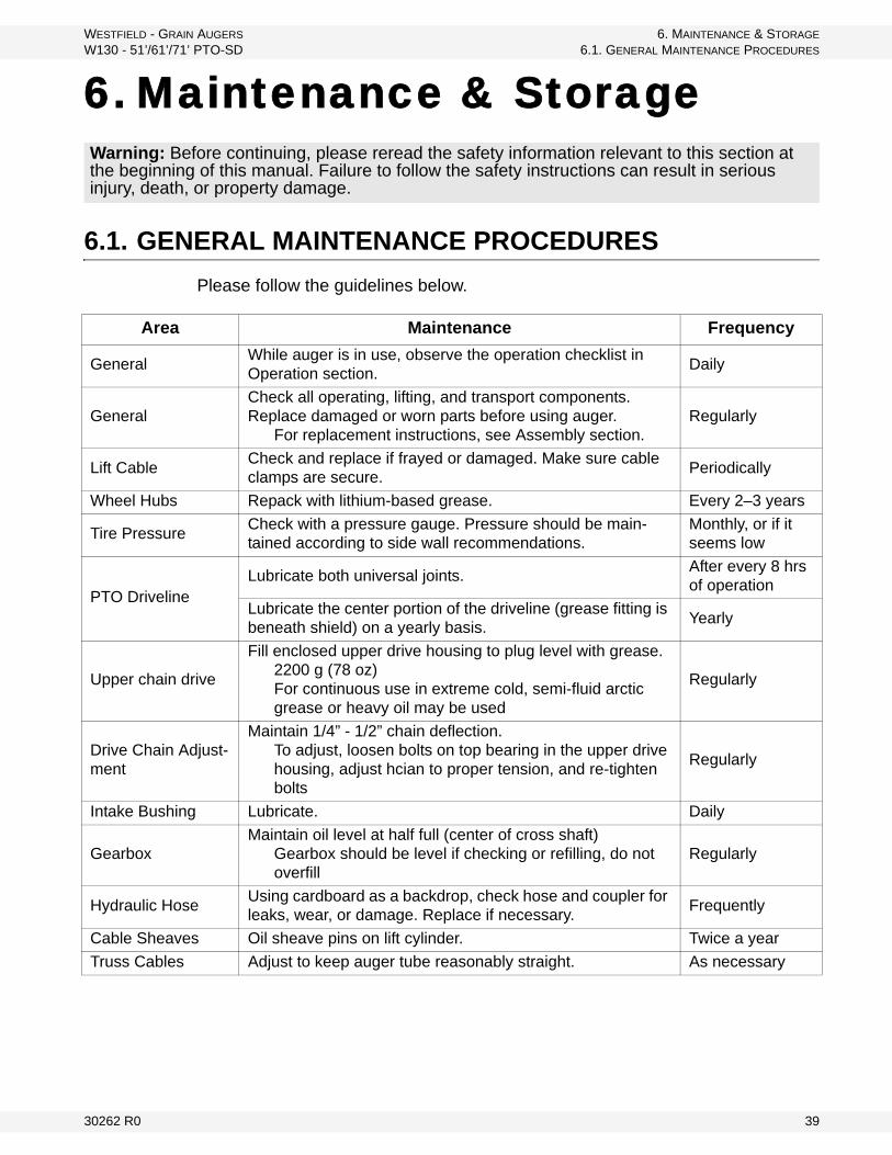
WESTFIELD - GRAIN AUGERS 6. MAINTENANCE & STORAGE
W130 - 51’/61’/71’ PTO-SD 6.1. GENERAL MAINTENANCE PROCEDURES
6. Maintenance & Storage
6.1. GENERAL MAINTENANCE PROCEDURES
Please follow the guidelines below.
Warning: Before continuing, please reread the safety information relevant to this section at the beginning of this manual. Failure to follow the safety instructions can result in serious injury, death, or property damage.
Area Maintenance Frequency
GeneralWhile auger is in use, observe the operation checklist in Operation section.
Daily
GeneralCheck all operating, lifting, and transport components. Replace damaged or worn parts before using auger.
For replacement instructions, see Assembly section.Regularly
Lift CableCheck and replace if frayed or damaged. Make sure cable clamps are secure.
Periodically
Wheel Hubs Repack with lithium-based grease. Every 2–3 years
Tire PressureCheck with a pressure gauge. Pressure should be main-tained according to side wall recommendations.
Monthly, or if it seems low
PTO DrivelineLubricate both universal joints.
After every 8 hrs of operation
Lubricate the center portion of the driveline (grease fitting is beneath shield) on a yearly basis.
Yearly
Upper chain drive
Fill enclosed upper drive housing to plug level with grease.2200 g (78 oz)For continuous use in extreme cold, semi-fluid arctic grease or heavy oil may be used
Regularly
Drive Chain Adjust-ment
Maintain 1/4” - 1/2” chain deflection.To adjust, loosen bolts on top bearing in the upper drive housing, adjust hcian to proper tension, and re-tighten bolts
Regularly
Intake Bushing Lubricate. Daily
GearboxMaintain oil level at half full (center of cross shaft)
Gearbox should be level if checking or refilling, do not overfill
Regularly
Hydraulic HoseUsing cardboard as a backdrop, check hose and coupler for leaks, wear, or damage. Replace if necessary.
Frequently
Cable Sheaves Oil sheave pins on lift cylinder. Twice a year
Truss Cables Adjust to keep auger tube reasonably straight. As necessary
30262 R0 39
6. MAINTENANCE & STORAGE WESTFIELD - GRAIN AUGERS
6.2. GENERAL STORAGE PROCEDURES W130 - 51’/61’/71’ PTO-SD
6.2. GENERAL STORAGE PROCEDURES
TO PROTECT AUGER IN STORAGE DURING THE OFF-SEASON:
1. Lower the auger to full down position with slight tension on the cable.2. Lubricate all grease fittings according to the maintenance procedure.3. Inspect auger for damage and note any repairs required. Order replacement
parts from your dealer.4. Check tire pressure and inflate if necessary. See tire sidewall for recommen-
dations.5. Clean and re-lubricate spline on PTO driveline. Cover PTO driveline with
plastic bag to protect it from the weather and place in the transport saddle.6. Tow auger to storage area. Park and chock wheels.
TO PREPARE AUGER FOR USE AFTER STORAGE:
1. Check tire pressure and inflate if necessary. See tire sidewall for recommen-dations.
2. Tow auger to work site.3. Remove cover from spline of PTO driveline and re-lubricate.4. Check oil level in gearbox and refill if necessary (half full only).5. Replace any damaged parts and decals.6. Check and perform general maintenance before using auger.7. Before raising auger after storage, make certain cable is in good condition,
replacing it if frayed or damaged. Also make sure cable is properly seated in the cable sheaves on the lift cylinder and that cable clamps are secure.
8. On augers equipped with lubricated upper drive, check level annually and add as needed (fill to plug level).
Note: Use only genuine Westfield replacement parts or equivalent. Replacement parts such as intake guards, pulley guards, PTO driveline shields, winches and lift cables Must meet ASAE standards or serious injury may result. Use of unauthorized parts will void warranty. If in doubt, contact Westfield or your Westfield dealer. Do not modify any auger components.
CAUTION
Support discharge end of auger before removing or replacing any parts on the undercarriage.
40 30262 R0

WESTFIELD - GRAIN AUGERS 7. TROUBLESHOOTING
W130 - 51’/61’/71’ PTO-SD
7. Troubleshooting
Problem Possible Cause Remedy
Excessive noise or vibra-tion.
*Remember to follow proper break-in proce-dures—auger may run rough until tube is pol-ished. If noise is extreme from outset or con-tinuous after several loads of grade are fed, continue with troubleshoot-ing below
Chatter from wooden bearings.
Spray penetrating lubricant between shaft and bearing surface. Bearings will break in over time.*If replacement of a bearing becomes neces-sary, split bearings are available to avoid having to slide all bearings off driveshaft.
Truss cables incorrectly adjusted.
Support end of auger and adjust cables so auger is flat or curves slightly upwards.
Flighting peeled back due to plugging.
Inspect spout end of auger for flight condition. Remove and replace flight sections as neces-sary.
Top drive inadequately lubri-cated.
Fill to appropriate level with grease.Top drive is not designed to be filled with oil.
Bent flighting sections.
Support auger and remove all flight sections. Check for straightness of flight stubs by rolling across flat concrete section. Straighten stub or replace as necessary. Take care not to bend flighting when reinstalling.
Obstruction in tube.Visually inspect for cloth or trash wrapped around flighting, or buildup of gum from oily crops such as flax or canola.
Shear bolts fail repeatedly.
Incorrect shear bolt type.Replace with correct part number. Westfield shear bolts are specifically designed to provide correct driveline protection.
Shear bolt hole worn out-of-round.
Frequent use of the incorrect shear bolt size can wear the mounting hole creating a “scissor effect,” which will require replacement of the affected parts.
Corn spreaders in bin unable to keep up with auger output.
Slow down auger or remove corn spreaders.
Flighting peeled back as a result of plugging.
Occurs when bin has overfilled, or corn spread-ers restrict end of discharge. Inspect flighting at discharge end of auger. If necessary, replace flighting.
Driveline failure (bearing, gear-box, etc.).
See Maintenance section.
30262 R0 41

7. TROUBLESHOOTING WESTFIELD - GRAIN AUGERS
W130 - 51’/61’/71’ PTO-SD
Premature wear on auger tubes.
Auger being run at low capacity or empty for extended period of time.
Frequently occurs on farms using grain wagons. Auger should not be left unattended when filling bins. Depending on application, a belt conveyor may be more appropriate.Bent flighting.
Flighting allowed to wear beyond normal point of replace-ment.
When flighting becomes razor-thin at intake, replacement is critical. Since flight material is double thickness at welded lap joints, high spots on flight occur and can accelerate spot tube wear.
Hydraulic lift settles out over time.
Shut off ball valve open.Oil is leaking through tractor valve. Auger ball valve should be closed whenever set up at bin.
Shut off ball valve leaking.Disconnect hose from tractor and check for leakage.
Lift cylinder cup seal leaking.Observe if oil leaks from cylinder rod wiper seal (may not be visible on dual action cylinders). Remove and replace cup seal.
Problem Possible Cause Remedy
42 30262 R0

WARRANTYWestfield Industries Ltd. warrants products of its manufacture against defects in materials or workmanship under normal and reasonable use for a period of one year after date of delivery to the original purchaser.
Our obligation under this warranty is limited to repairing, replacing, or refunding defective part or parts which shall be returned to a distributor or a dealer of our Company, or to our factory, with transportation charges prepaid. This warranty does not obligate Westfield Industries Ltd. to bear the cost of labor in replacing defective parts. Any defects must be reported to the Company before the end of the one year period.
This warranty shall not apply to equipment which has been altered, improperly assembled, improperly maintained, or improperly repaired so as to adversely affect its performance. Westfield Industries Ltd. makes no express warranty of any character with respect to parts not of its manufacture.
The foregoing is in lieu of all other warranties, expressed or implied, including any warranties that extend beyond the description of the product, and the IMPLIED WARRANTY of MERCHANTABILITY is expressly excluded.
WESTFIELD INDUSTRIES LTD.
ROSENORT, MANITOBA
CANADA
R0G 1W0
Westfield is a Division of Ag Growth Industries LP
Part of the Ag Growth International Inc. Group
P.O. Box 39
Rosenort, Manitoba, Canada R0G 1W0
Phone: (866) 467-7207 (Canada & USA)
Fax: (866) 768-4852
website: www.grainaugers.com
email: [email protected]
© Ag Growth Industries Limited Partnership 2009
Printed in Canada