Embed Size (px)
Citation preview
School of Mathematics and Systems Engineering
Reports from MSI - Rapporter från MSI
Grail to XMI and Back
Chao Wang
Jun
2008
MSI Report 08063
Växjö University ISSN 1650-2647
SE-351 95 VÄXJÖ ISRN VXU/MSI/DA/E/--08063/--SE
Master Thesis
Grail to XMI and Back Chao Wang
2008
Department of Computer Science School of Mathematics and System Engineering
Växjö University
Supervisor: Prof. Dr. Welf Löwe
i
Acknowledgements First of all, I would like to thank my family and friends for their support from beginning to the end during the time I worked on this thesis project. I would like to thank my supervisor Prof. Dr. Welf Löwe for guiding and supporting me during this period, without him, I would not have finished this bachelor thesis in such a short time. I also want to appreciate Prof. Mathias Hedenborg for giving us a lot comments about the thesis. I would also like to thank Rüdiger Lincke for his suggestion and introduction about my thesis study. Especially, I want to express my gratitude to my two colleagues, who help and support me a lot.
ii
Abstract Grail is an open source graph library, which is developed at the MSI of Växjö
University, tools like the VizzAnalyzer and vizz3d use Grail for representing their
internal structures.
In this thesis, an adapter serializing and deserializing Grail graphs to and from XMI
is introduced. XMI is short for XML Metadata Interchange; it is developed by the
Object Management Group (OMG).
The problem of this thesis is to design a serializer/deserializer architecture which
is technically used to connect the tools (like the VizzAnalyzer and vizz3d) to other
related tools. This adapter is designed for serializing and deserializing Grail graphs to
and from XMI (XML Metadata Interchange).
This problem can be divided into two parts: Serializing and De-serializing. Here
comes the result of the thesis: when serializing, this adapter is able to recognize a Grail
graph (we call it original graph), and gather all the information of that graph; for
instance, nodes, edges and their attributes. The adapter can store these data into an XMI
document represented in XML syntax. Meanwhile, an XMI schema is created to
validate the XMI document. When de-serializing, the adapter can access an XMI
document, and rebuild a grail graph (we call it final graph) accoding to the data stored
in the XMI document. The original graph and the final graph are proved the same in
chapter 4.
In the end, a brief conclusion is made overall the thesis. Because of the restriction
of some reasonable factors, the future work is discussed to make you be clear about
what kind of idea that I cannot follow in this thesis, and I will improve it in the future.
Keywords of this report are: Grail, Graph, XMI, XMI Schema, XML, UML, OMG, Converter
iii
Table of Contents
1. INTRODUCTION .......................................................................................................................... 1
1.1 PROBLEM ........................................................................................................................................ 1
1.2 GOAL ............................................................................................................................................. 1
1.3 CRITERIA ......................................................................................................................................... 2
1.4 RESTRICTIONS .................................................................................................................................. 3
1.5 MOTIVATION .................................................................................................................................... 3
1.6 STRUCTURE OF THE THESIS .................................................................................................................. 3
2. DEFINITIONS AND STATE OF THE ARTS ........................................................................................ 5
2.1 BASIC THEORY .................................................................................................................................. 5
2.1.1 Grail ......................................................................................................................................... 5
2.1.2 UML (Unified Modeling Language) .......................................................................................... 5
2.1.3 XML (EXtensible Markup Language) ........................................................................................ 8
2.1.4 XMI (XML Metadata Interchange) ......................................................................................... 10
2.2 STATE OF THE ARTS OF TOOLS SUPPORTING XMI ................................................................................... 16
2.3 REFINE OBJECTIVES .......................................................................................................................... 16
2.4 TERMINOLOGY ............................................................................................................................... 17
2.5 OTHER RELATED WORKS ................................................................................................................... 19
3. ANALYSIS AND DESIGN .............................................................................................................. 20
3.1 BASIC IDEAS ABOUT WRITING OBJECTS USING XMI ................................................................................ 20
3.2 ANALYSES STEPS FROM GRAIL TO XMI AND BACK .................................................................................. 22
3.2.1 Serializing .............................................................................................................................. 22
3.2.2 Deserializing .......................................................................................................................... 24
3.3 CONCLUSION ................................................................................................................................. 24
4. IMPLEMENTATION ..................................................................................................................... 25
4.1 A DEMO IMPLEMENTATION ............................................................................................................... 25
4.1.1 Flow or progress of my implementation ................................................................................ 25
4.1.2 Serializing .............................................................................................................................. 26
4.1.3 Deserializing .......................................................................................................................... 29
4.2 VERIFICATION ................................................................................................................................. 31
5. CONCLUSION AND FUTURE WORK ............................................................................................. 32
5.1 CONCLUSION ................................................................................................................................. 32
5.2 FUTURE WORK ............................................................................................................................... 32
REFERENCE........................................................................................................................................ 34
A. APPENDIX FOR DOCUMENTATIONS ............................................................................................ 35
A.1 FURTHER MOF (META-OBJECT FACILITY) ............................................................................................ 35
A.2 XMI DOCUMENT OF EXAMPLE ........................................................................................................... 35
A.3 SOURCE CODE ................................................................................................................................ 36
A.3.1 Key methods of Serializing ..................................................................................................... 37
A.3.2 Key methods of Deserializing ................................................................................................. 48
iv
List of Figures FIGURE 2.1 GRAIL CLASSES IN CLASS DIAGRAM ............................................................................................... 5
FIGURE 2.2 UML CLASS NOTATION AND ITS IMPLEMENTATION IN JAVA ......................................................... 6
FIGURE 2.3 A SIMPLE OBJECT DIAGRAM ........................................................................................................ 7
FIGURE 2.4 RELATIONSHIP OF XMI, XML AND UNICODE .............................................................................. 10
FIGURE 2.5 ROLE OF XMI IN MODEL TRANSFORMATION ................................................................................ 11
FIGURE 2.6 XMI, INTEROPERABILITY AND ECLIPSE FUNCTIONALITY ............................................................... 12
FIGURE 2.7 USING XMI TO EXCHANGE OBJECTS AMONG TOOLS ..................................................................... 13
FIGURE 2. 8 AN XML REPRESENTATIONS OF GRAPH DATA ........................................................................... 15
FIGURE 2.9 THE RELATIONSHIP BETWEEN A UML MODEL, AN XMI DOCUMENT, AND AN XMI SCHEMA. ..... 15
FIGURE 3.1 DEFINITION OF GRAPH DATA MODEL ......................................................................................... 22
FIGURE 3.2 THE XMI PROCESS .................................................................................................................... 23
FIGURE 4.1 LAYOUT OF A DEMO GRAPH VISUALIZED IN YED ....................................................................... 25
FIGURE 4.2 FLOW OF GRAIL TO XMI AND BACK ......................................................................................... 26
FIGURE 4.3 GRAIL GRAPH MODEL .............................................................................................................. 27
v
List of Tables TABLE 2.1 MULTIPLICITY EXAMPLES ............................................................................................................ 6
TABLE 2.2 UML AND JAVA COMPARISON ..................................................................................................... 7
TABLE 2.3 XMI VERSIONS ............................................................................................................................ 12
TABLE 2.4 XMI SUPPORTING TOOLS IN DIFFERENT VERSIONS ..................................................................... 16
TABLE 4.1 ADDXMIVALUE() BEHAVIOR ...................................................................................................... 28
TABLE A.1 MOF METADATA ARCHITECTURE ............................................................................................... 35
1
1. Introduction Recently, exchanging formats, which is also a problem of this thesis, have gained lots of attention. Multiple tools (Tools like the VizzAnalyzer and vizz3d) need to interact and work on the same software system.
By tradition, the research fields of theoretic under a wide development in practical
applications are characterized by a rapid tool development of various complexities.
Each of these tools, which are made by individual research groups, has its own feature,
but each of these tools lacks of generality; they are different from each other in applied
graph transformation approach, and in the fundamental data structures as well.
In addition, people cannot always do a huge project all by oneself, so the
significance of cooperation is proved obviously. In the last decade, the amount of
international projects in the world is increasing rapidly. A good coordination between
the partners is required by such projects, the projects which are international projects
with different research groups from different countries. Besides, by this coordination,
the efficient integration and interaction of individually developed tools become
necessary.
The main point of such a wide interaction is a common standardized exchange
format (e.g. Grail to XMI), intended to serve as a fundamental data structure for
software modules of different tools.
What’s more, it is worthwhile to construct such a format that supports the
distributed development of tools and the interchange of tool data. As a result of its
flexibility and rapid development, developers turn the attention to the structured
language of the web, the Extensible Markup Language (XML).
1.1 Problem
In this thesis, we will introduce how to design a serializer/deserializer architecture
which is technically used to connect the tools (like the VizzAnalyzer and vizz3d) to
other related tools. This adapter is designed for serializing and deserializing Grail
graphs to and from XMI (like a reverse engineering), XML Metadata Interchange,
developed by the Object Management Group (OMG). In other words, this adapter can
read data in a graph that is generated by grail (Java graph library) and store the data into
a specified XMI document. Besides, this adapter should be able to parse the file with
XMI format, read the data stored in this file, and translate these data into graph.
1.2 Goal
Grail is a Java library for capturing and manipulating graphs. Tools like the VizzAnalyzer and vizz3d use Grail for representing their internal structures. “XMI
(XML Metadata Interchange) is OMG standard for exchanging (meta)data between
tools, repositories and applications.” See [9]. It works with and builds on existing industry standards; these are W3C XML, OMG UML and MOF.
“XMI is a widely used interchange format for sharing objects using XML. Sharing
objects in XML is a comprehensive solution that builds on sharing data with XML. XMI
is applicable to a wide variety of objects: analysis (UML), software (Java, C++),
2
components (EJB, IDL, Corba Component Model), and databases (CWM). Over 30
companies have XMI implementations.” We can see this explanation in [9].
Graphs are a widely used data structure in software engineering due to their
mathematical foundation and algorithmic power. Different graph models, for instance,
directed graphs, undirected graphs, node attributed graphs, edge attributed graphs,
node typed graphs, edge typed graphs, ordered graphs, relational graphs, acyclic
graphs, trees, etc. or combinations of these graph models are used in many software
systems. To support interoperability of graph based tools, the underlying graph model
has to be as rich as possible to cover most of these graph models.
To improve the interoperability of software system, exchanging formats from Grail
to XMI or from XMI to Grail is the problem which is worthwhile for us to pay more
attention to.
In order to connect the tools, which I mentioned above, to others, we need an
adapter, serializing and deserializing Grail graphs to and from XMI. The practical goal
of the thesis project is to design such serializer/deserializer architecture and implement
it in Java.
1.3 Criteria
The solution makes the tools (like the VizzAnalyzer and vizz3d) connect to other tools easily. The following criteria should be taken into account.
1) Generality The adapter is designed for serializing and deserializing Grail graphs to and from XMI,
it is used for connecting tools from each other. Any tool that uses Grail for representing
its internal structure can use this adapter. So, obviously, generality is the important
criteria which should be considered.
2) Modularization Modularization can be considered as an encapsulation of a class, for instance, a class
provides an interface for user to call the methods in it, and the user does not have to care
about that how it is implemented inside. Besides, this interface can be used in many
different kinds of cases, it has expansibility. So it needs much more attention when
designing a module like that. We should consider that whether this module can still
work when disengaging the current system, and whether it can be used directly in other
systems or application environments after change some parameters, and so forth.
However, it will make the job more complicated.
3) Extensibility The first design of every product always cannot be perfect, so the first designer should
make the product be easily updated by other developers. For this solution, it is easy for
the developer to add new performance to the tools, according to different types of graphs.
Moreover, other converters, like GXL converter and SQL converter, can be integrated
with XMI converter conveniently
3
1.4 Restrictions
Because of some reasonable factors, the solution accepts only the graphs created by Grail, for other graphs, it does not work well. Besides, it can only convert the grail graph to XMI document. In other words, it does not support other formats (like GXL, SQL).
In my thesis, a grail graph is created firstly. This graph will be converted into XMI document by the converter. Secondly, the grail graph will be rebuilt from the XMI document again. Finally, we will compare the original grail graph to the final grail graph by visualizing the grail graph in yEd tool (a very powerful graph editor).
Here comes another restriction. When serializing, we get a name of attribute of the original grail graph. In this attribute name, some characters are not allowed to be used in the XMI attribute name, like ‘(’, ‘)’ and so on. These characters are called reserved characters. The attribute name containing the reserved characters can not be stored into XMI document directly, so they are deleted, but not added back to the name of attribute of final grail graph when deserializing. So the situation that the attribute name of original graph and final graph are not the same may exist. But this will not affect the functionality of the whole project.
Plus, when it comes to an extremely large graph, the efficiency of execution (performance) is not good.
For future work, I am supposed to handle these problems which are mentioned above.
1.5 Motivation
Firstly, as I mentioned in the beginning, exchanging formats is becoming more and more important nowadays in order to make multiple tools interact and work on the same software.
Secondly, due to their mathematical foundation and algorithmic power, graphs are a
widely used data structure in software engineering. Different graph models are used in
many software systems.
Thirdly, in order to gain a good cooperation between different groups or different
tools, it is worthwhile to construct such a format that supports the distributed
development of tools and the interchange of tool data, which can be used to store the
information of graphs in. As a result of its development, XMI is one of the best choices,
which is based on the structured language of the web, the Extensible Markup Language
(XML).
Besides, XMI is a widely used interchange format for sharing objects using XML.
Because of XMI’s capability to represent many forms of object-oriented information,
software that supports XMI can be used to provide lightweight integration among Java
applications, the Web, XML, and different kinds of models. So it is wise to choose XMI
data format for storing the information of graphs. It is helpful and meaningful for the
computer world to design such an adapter.
1.6 Structure of the thesis
My thesis is structured as follows.
� Chapter 2 introduces the basic theory (including grail, UML, XML, XMI and
4
XMI schema) of this thesis. Some tools that support XMI are listed. Moreover,
some basic terminologies that are concerned in this thesis are given. And the
refined objective is put forward in the end of this chapter. � Chapter 3 introduces some APIs (Application Programming Interface) that
support XMI, and explains how to represent simple objects and their parts using
XMI. In addition, I make an analysis of this project, and explain the steps how to
create XMI document from grail graph and vice versa.
� Chapter 4 gives a demo implementation of this project, and shows how we
verify the solution. � Chapter 5 makes a conclusion of this thesis, and describes what I need to do for
future work.
5
2. Definitions and State of the arts This chapter gives an overview of the theory behind the project. Some basic ideas about
UML, XML and XMI and the relationship between them are explained. Then XMI
Schema is introduced. Besides, a simple example is given to help understanding the
ideas well. And a refined objective of this project is established, too.
2.1 Basic theory
2.1.1 Grail GRAIL: Graph Library, a Java library for capturing and manipulating graphs, it is an open source library, which is developed at the MSI of Växjö University, tools like the VizzAnalyzer and vizz3d use Grail for representing their internal structures.
Grail consists of an annotated graph (instantiated from our graph library), where
each graph entity (nodes, edges, and the graph itself) has a data object and a set of
predicates attached to it.
Grail graph contains three types of elements:
• Node is some element (class, interface, method, field…)
• Edge is the relation between two elements (call, inheritance…)
• Graph is a collection of nodes and edges The open source tool Grail is used to create graph from a source file. Grail uses the
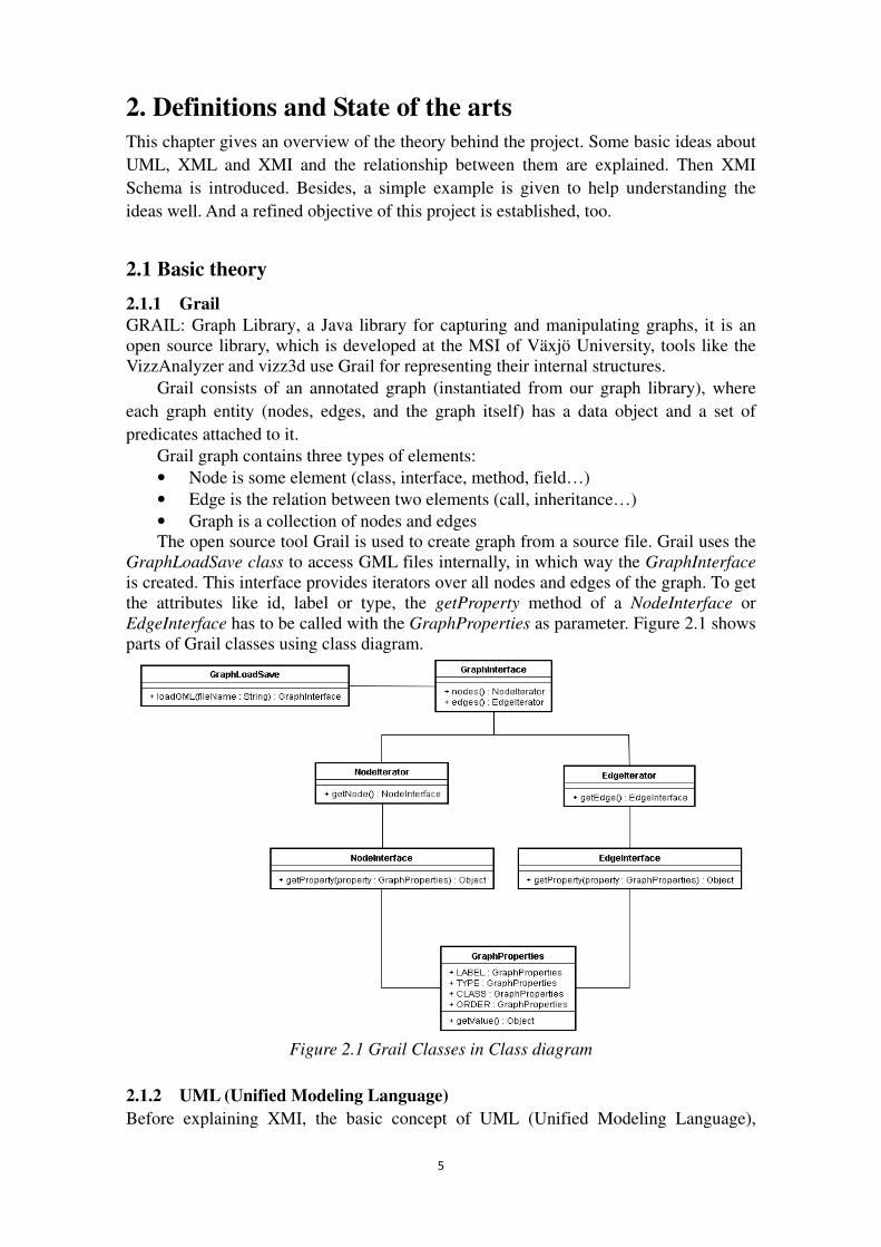
GraphLoadSave class to access GML files internally, in which way the GraphInterface is created. This interface provides iterators over all nodes and edges of the graph. To get the attributes like id, label or type, the getProperty method of a NodeInterface or EdgeInterface has to be called with the GraphProperties as parameter. Figure 2.1 shows parts of Grail classes using class diagram.
Figure 2.1 Grail Classes in Class diagram
2.1.2 UML (Unified Modeling Language) Before explaining XMI, the basic concept of UML (Unified Modeling Language),
6
which is one of the standards related to XMI, should be discussed. The other standards
XML will be discussed later soon. These two standards (XML and UML) are most
relevant to XMI.
“UML (Unified Modeling Language) is a visual modeling language used for
specifying, visualizing, constructing, developing and documenting the artifacts of
software systems by various diagrams.” See [5] [10] in detail. The industry accepted
standard versions of UML are regulated by OMG.
When it comes to using XMI, the data (The data in this thesis is generated by Grail)
must be in objects themselves or be mapped to objects. The concepts of classes,
instances, and inheritance are implemented by most object-oriented systems. For
instance, Java implements all of these concepts. These concepts are defined by object
models, and UML is an example of such a model. Another object model is the Meta
Object Facility (MOF). It is the object model for XMI. Since UML and MOF are
closely associated, and the OMG is working to make them even more closely associated
in the future, we do not need to know much about MOF to use XMI for this current
project. UML models can be mapped to MOF models, so we use UML models in this
thesis rather than MOF models.
The object-oriented concepts that are relevant to XMI are the concepts that describe
the state of objects. The methods are behavioral aspects of objects. They are not part of
an object’s state, so it is not necessary to preserve them. For example, the state of a Java
object is the value of its fields. UML defines the state of objects, too. UML also defines
a graphical notation for UML models that is convenient for accurately defining the data.
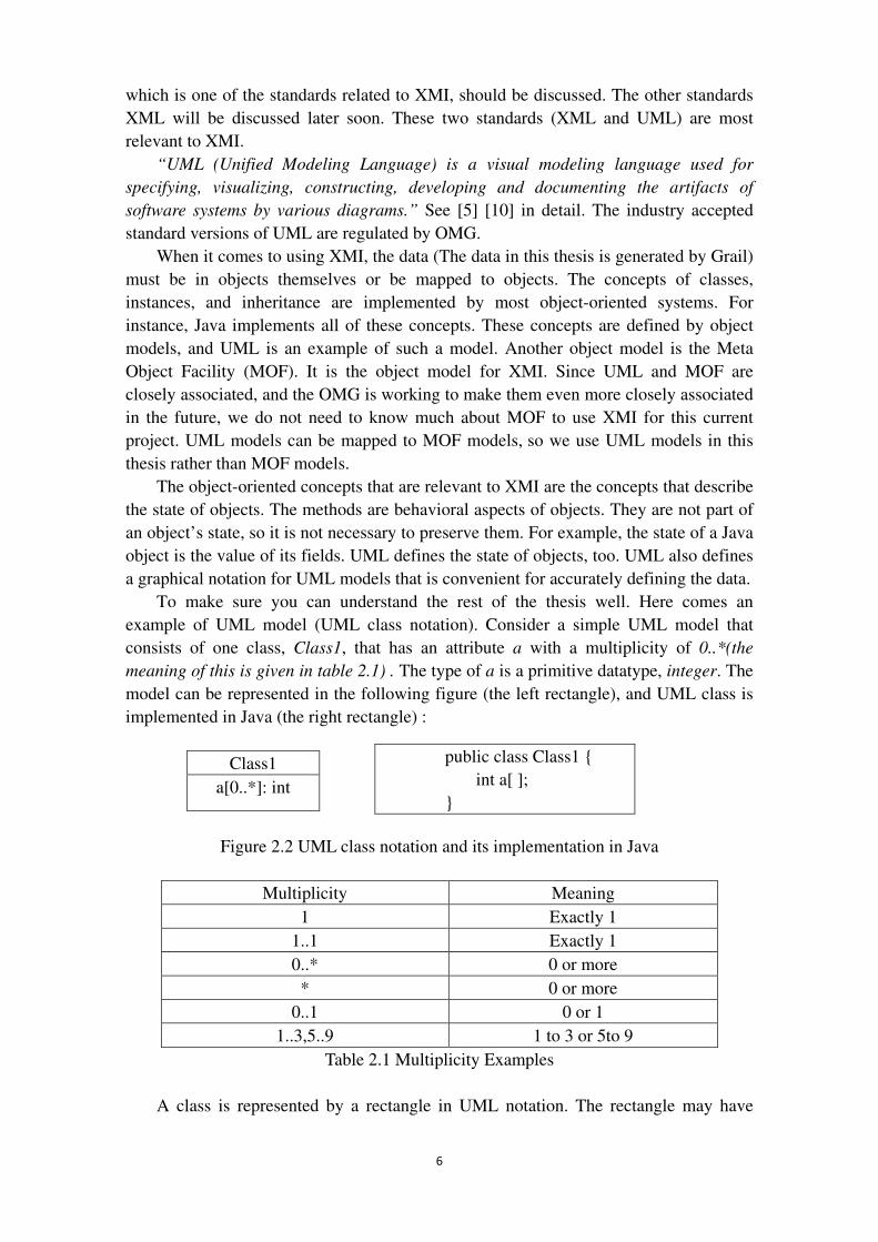
To make sure you can understand the rest of the thesis well. Here comes an
example of UML model (UML class notation). Consider a simple UML model that
consists of one class, Class1, that has an attribute a with a multiplicity of 0..*(the
meaning of this is given in table 2.1) . The type of a is a primitive datatype, integer. The
model can be represented in the following figure (the left rectangle), and UML class is
implemented in Java (the right rectangle) :
Class1
a[0..*]: int
Figure 2.2 UML class notation and its implementation in Java
Multiplicity Meaning
1 Exactly 1
1..1 Exactly 1
0..* 0 or more
* 0 or more
0..1 0 or 1
1..3,5..9 1 to 3 or 5to 9
Table 2.1 Multiplicity Examples
A class is represented by a rectangle in UML notation. The rectangle may have
public class Class1 {
int a[ ];
}
7
three sections: The top section contains the name of the class, the middle section
contains the attributes, and the bottom section contains the operations. Not all of these
sections need to be displayed in a class diagram. The example given above has only two
sections, the top section and the middle section.
The UML model is expressed graphically, that is, UML provides a standard
graphical notation for analyzing and designing object-oriented systems.
There are some other notations in UML model; these are UML inheritance notation,
UML package notation, UML association notation, UML unidirectional association
notation, UML aggregation notation, UML composition notation, UML datatype
notation and so forth.
UML contains the concept of an object as well as a class. A UML object is an
instance of a UML class. UML objects have attribute values and link ends, which are
instances of association ends.
Objects can be illustrated in UML object diagrams. Each object is represented by a
rectangle. The name of the object and the name of the class can be included in the object.
Figure 2.3 shows an object diagram representing an object called obj1 that is an instance
of a class Nodes.
Obj1: Nodes
Figure 2.3 A simple object diagram
To help you understand the concept of UML well. Table 2.2 lists the concepts in
UML that are relevant to XMI and the corresponding Java concept, if there is one. The
UML concepts that are not in the Java language can be implemented in Java though.
UML CONCEPT JAVA CONCEPT
Class Class
Attribute Field
Association None
Association end None
Single inheritance Inheritance
Multiple inheritance None
Instance Instance
Package Package
Datatype Primitive type
Table 2.2 UML and Java Comparison
� The importance of UML It is necessary to define what an object is, regardless what the programming language
will be used in an application, to share objects written in different programming
languages. UML provides such a definition. A standard graphical notation for analyzing
and designing object-oriented systems is also provided in UML.
UML can be used whatever the programming language the system will be
implemented in. UML enables programmers to model their applications and the data in
it, and then implement the model in the programming language which is the best
compatible for the application. UML has been adopted by the Object Management
8
Group (OMG), “a software industry consortium that supports the interoperability of
object-oriented technology through open standards” [1]. Since UML provides a
standard definition of what an object is, it can be used to define the objects that are to be
shared among different applications. From [1], we can see UML is flexible.
“Combining UML with a standard way to represent data enables objects to be shared
effectively using standards rather than individual technology”.
2.1.3 XML (EXtensible Markup Language) “XML combines the advantages of its predecessors (the simplicity of HTML and
document structure description of SGML) into an easily parsable and verifiable
language which is desired to play a major role in the next generation of Internet
applications.” This is said in [3].
XML is a markup language that is similar to HTML (Hypertext Markup Language).
It specifies a way to format data in a file. The tags of XML is not predefined in XML
syntax, you should define the tags by yourself when using XML. XML uses DTDs
(Document Type Definition) or XML schemas to describe data. XML represents data
using XML elements, which consist of the following parts:
1) A start tag, which has a name for the element.
2) XML attributes; each attribute has a name and a value.
3) Content, which consists of text, other XML elements, or a combination of the
two.
4) An end tag, which has a name that is the same as the name of the start tag.
Example of XML Here is an example of legal XML elements:
<edge type="directed ">
<from id="n1"/>
<to id="n2"/>
</ edge>
<comment> An edge of one graph</comment>
There are five XML elements. The edge element has an attribute called type and its
value is directed. The content of the edge element consists of from element and to
element, each of them has an attribute called id. The comment element has text in its
content.
� The importance of XML XML has come forward as a powerful and easy way to save data in files. Because it is a
standard, XML enables you to save data in a specified form that can be accessed by
applications, but it cannot create the data. By using standard application programming
interfaces (APIs), e.g. DOM, SAX, XML software enables you to access the data in
XML documents.
XML is flexible. Data can be represented in more than one way. This flexibility is
good because it enables you to design an XML representation that is right for your
applications, but it causes problems when attempting to share XML documents. To
exchange data using XML, you need to do the following:
9
1. Define the data to be exchanged.
2. Decide how to represent the data in XML.
If you do not define your data, you cannot exchange it with others, regardless of the
representation of the data, so the first step is necessary to exchange data using any
technology.
� Drawback of XML Although, as I refer to above, XML has a lot advantages itself, there exists a slit
between XML and object. XML is not object-oriented. XML defines XML elements
and XML attributes, not objects. They do not support object-oriented features as
multiple inheritances, and they do not include an object model, either. There exist
different ways of storing data in XML, and if tools storing data using XML differently,
it is difficult for tools exchange data with each other. The situation is the same for
representing object in XML, if objects are stored differently in XML; it is difficult to
exchange them among tools.
However, XMI bridges the gap between objects and XML. It provides a standard
mapping from objects defined by UML to XML. So that is why XMI is used.
� The relationship between XMI and XML XMI uses XML, so XMI document will also gain benefits, when the efforts are put
underway to make XML documents easier to produce. However, to use XMI, it does not
require you to be an XML expert. XMI software can make it easy to produce XMI
documents without dealing with XML elements and attributes directly.
As XML technologies are adopted by the W3C, XMI evolves to use them. We can
see the following content, which is described in [1]. “For example, since XML
namespaces were not a recommendation of the W3C when XMI 1.0 was standardized,
XMI 1.0 could not use them. However, by the time XMI 1.1 was standardized, the XML
Namespace specification was an official recommendation of the W3C, so XMI 1.1 uses
XML namespaces to produce more compact XMI documents than was possible with
XMI 1.0. Now that XML schemas have been officially adopted as a recommendation by
the W3C, XMI 2.0 specifies how to create schemas from UML models as well as how to
produce smaller XMI documents than XMI 1.1. XMI will continue to evolve to use
future XML technologies, as appropriate.”
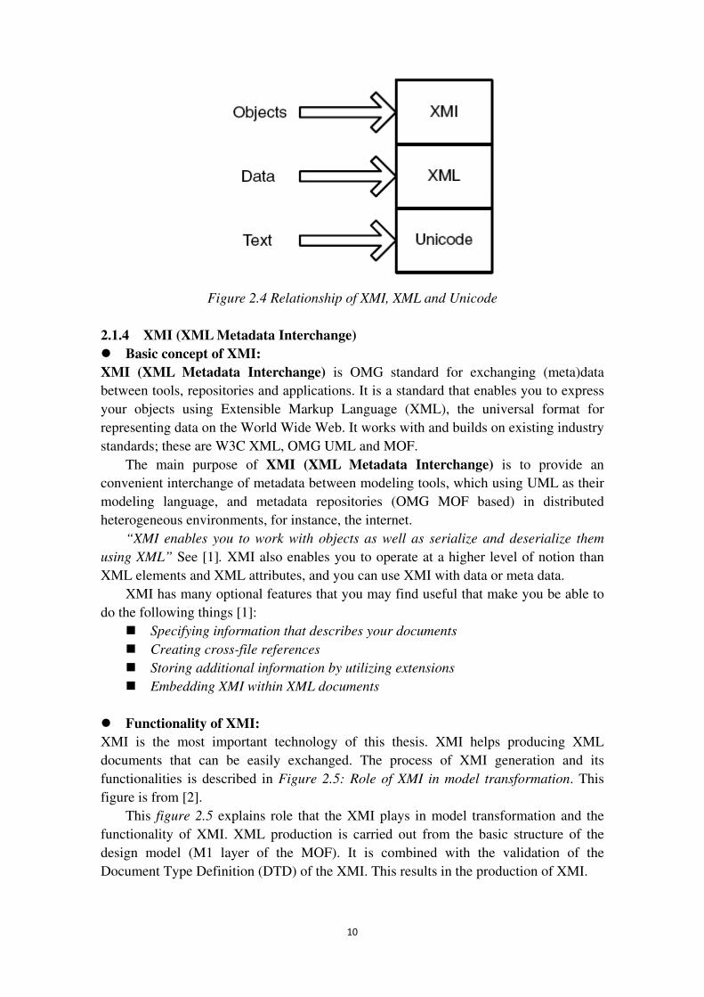
XMI does not extend XML, but it builds upon XML. For the purpose of
representing data, XML builds upon Unicode, which is a standard for specifying
characters in different languages. In the same way, in order to represent objects, XMI
builds upon XML. Figure 2.4 describes this concept. Because of this relation, every
XMI documents is an XML documents, and every XMI schema is an XML schema.
10
Figure 2.4 Relationship of XMI, XML and Unicode
2.1.4 XMI (XML Metadata Interchange) � Basic concept of XMI: XMI (XML Metadata Interchange) is OMG standard for exchanging (meta)data
between tools, repositories and applications. It is a standard that enables you to express
your objects using Extensible Markup Language (XML), the universal format for
representing data on the World Wide Web. It works with and builds on existing industry
standards; these are W3C XML, OMG UML and MOF.
The main purpose of XMI (XML Metadata Interchange) is to provide an
convenient interchange of metadata between modeling tools, which using UML as their
modeling language, and metadata repositories (OMG MOF based) in distributed
heterogeneous environments, for instance, the internet.
“XMI enables you to work with objects as well as serialize and deserialize them
using XML” See [1]. XMI also enables you to operate at a higher level of notion than
XML elements and XML attributes, and you can use XMI with data or meta data.
XMI has many optional features that you may find useful that make you be able to
do the following things [1]:
� Specifying information that describes your documents
� Creating cross-file references
� Storing additional information by utilizing extensions
� Embedding XMI within XML documents
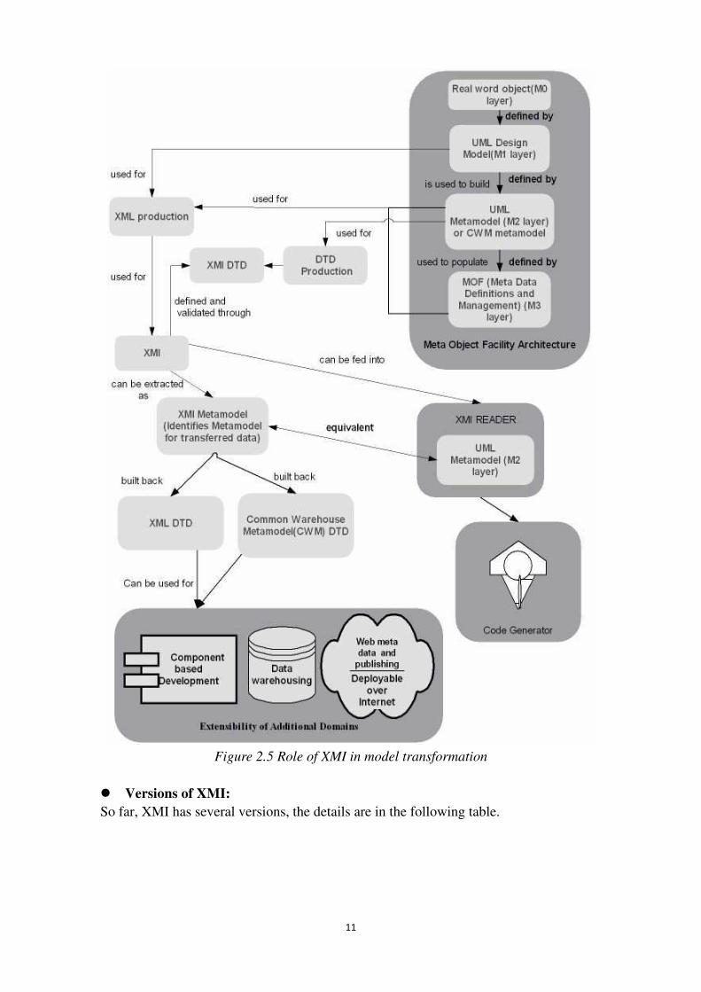
� Functionality of XMI: XMI is the most important technology of this thesis. XMI helps producing XML
documents that can be easily exchanged. The process of XMI generation and its
functionalities is described in Figure 2.5: Role of XMI in model transformation. This
figure is from [2].
This figure 2.5 explains role that the XMI plays in model transformation and the
functionality of XMI. XML production is carried out from the basic structure of the
design model (M1 layer of the MOF). It is combined with the validation of the
Document Type Definition (DTD) of the XMI. This results in the production of XMI.
11
Figure 2.5 Role of XMI in model transformation
� Versions of XMI: So far, XMI has several versions, the details are in the following table.
12
XMI version Comments
1.0 Oldest version
1.1 ---
1.2 Commonly used XMI version
1.3 Least used XMI version
2.0 Most targeted(used in this thesis)
2.1 Targeted
Table 2.3 XMI versions � Benefits of XMI: There are many benefits to using XMI. XMI enables you to work with objects as well as
serialize and deserialize them using XML.
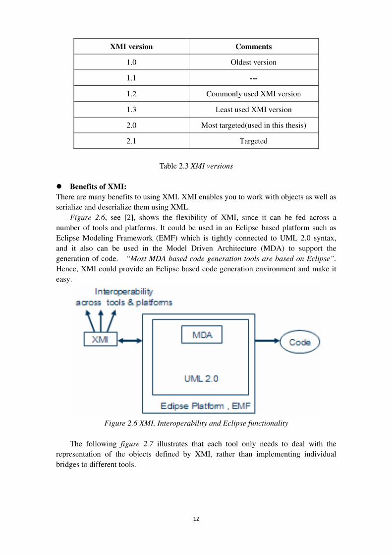
Figure 2.6, see [2], shows the flexibility of XMI, since it can be fed across a
number of tools and platforms. It could be used in an Eclipse based platform such as
Eclipse Modeling Framework (EMF) which is tightly connected to UML 2.0 syntax,
and it also can be used in the Model Driven Architecture (MDA) to support the
generation of code. “Most MDA based code generation tools are based on Eclipse”.
Hence, XMI could provide an Eclipse based code generation environment and make it
easy.
Figure 2.6 XMI, Interoperability and Eclipse functionality
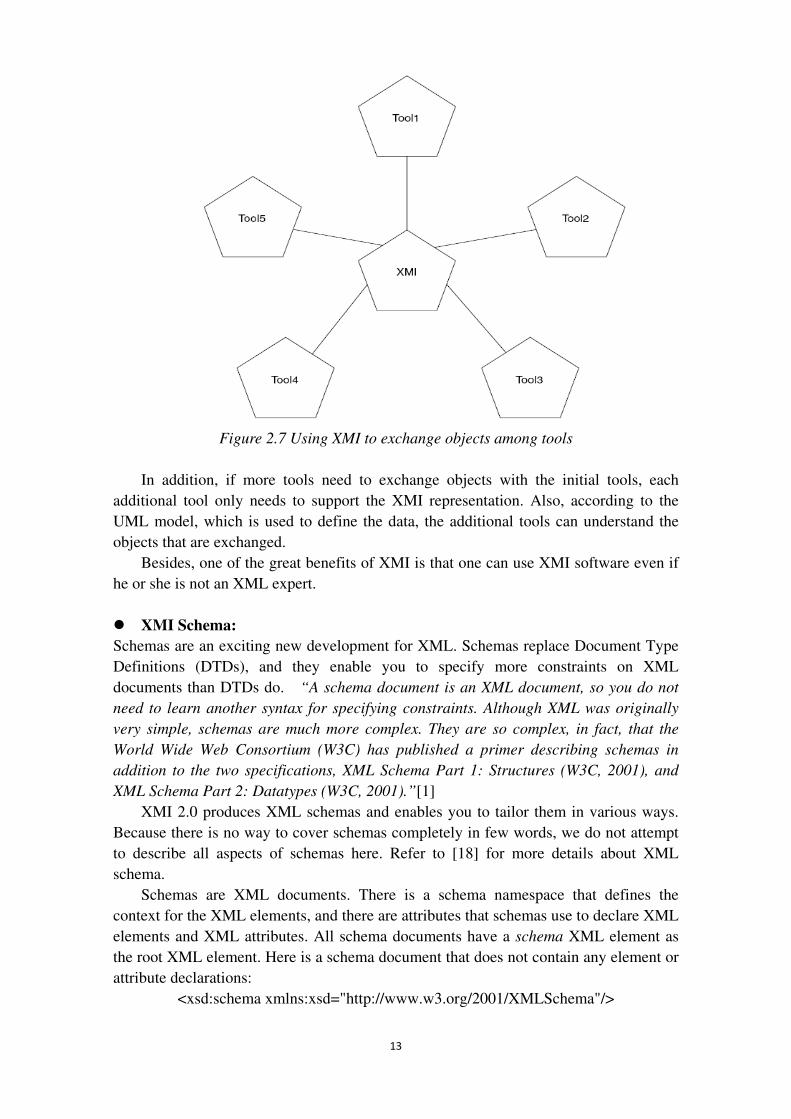
The following figure 2.7 illustrates that each tool only needs to deal with the
representation of the objects defined by XMI, rather than implementing individual
bridges to different tools.
13
Figure 2.7 Using XMI to exchange objects among tools
In addition, if more tools need to exchange objects with the initial tools, each
additional tool only needs to support the XMI representation. Also, according to the
UML model, which is used to define the data, the additional tools can understand the
objects that are exchanged.
Besides, one of the great benefits of XMI is that one can use XMI software even if
he or she is not an XML expert.
� XMI Schema: Schemas are an exciting new development for XML. Schemas replace Document Type
Definitions (DTDs), and they enable you to specify more constraints on XML
documents than DTDs do. “A schema document is an XML document, so you do not
need to learn another syntax for specifying constraints. Although XML was originally
very simple, schemas are much more complex. They are so complex, in fact, that the
World Wide Web Consortium (W3C) has published a primer describing schemas in
addition to the two specifications, XML Schema Part 1: Structures (W3C, 2001), and
XML Schema Part 2: Datatypes (W3C, 2001).”[1]
XMI 2.0 produces XML schemas and enables you to tailor them in various ways.
Because there is no way to cover schemas completely in few words, we do not attempt
to describe all aspects of schemas here. Refer to [18] for more details about XML
schema.
Schemas are XML documents. There is a schema namespace that defines the
context for the XML elements, and there are attributes that schemas use to declare XML
elements and XML attributes. All schema documents have a schema XML element as
the root XML element. Here is a schema document that does not contain any element or
attribute declarations:
<xsd:schema xmlns:xsd="http://www.w3.org/2001/XMLSchema"/>
14
Each element declared in a schema uses the predefined XML element called
element. The name attribute of that element is the name of the element. Here are some
element declarations:
<xsd:element name="Node"/>
<xsd:element name="Edge"/>
The first element has a name of Node, and the second element has a name of Edge.
XML elements that validate against these schema declarations will have tag names of
Node and Edge, respectively.
You can specify the type of an element by using the type attribute for the element
XML element. You declare a complex type by using a complexType XML element. The
following example declares a complex type called NodeType and specifies that an
element Node is of that type:
<xsd:complexType name="NodeType"/>
<xsd:element name="Node" type =" NodeType "/>
You can declare attributes as well as elements and element content in schemas. You
use the xsd:attribute XML element to do so. That element has name, type, use, default,
and fixed attributes that enable you to specify information about the attribute and its
values. Here are some examples of attribute declarations:
<xsd:complexType name="someAttributesofNode">
<xsd:sequence>
<xsd:element name="Node"/>
</xsd:sequence>
<xsd:attribute name="b1" type="xsd:string" use="optional" default="MyDefault"/>
<xsd:attribute name="b2" type="xsd:string" fixed="FixedValue"/>
<xsd:attribute name="b3" type="xsd:string" use="required"/>
<xsd:attribute name="b4" type="xsd:string"/>
</xsd:complexType>
In this example there are four attribute declarations. Attribute b1 is optional; if it
does not appear, a validating parser will supply the value MyDefault for it. If it does
appear, the parser will use the actual value that appears. Attribute b2 is also optional;
however, if it does appear, it must have the value FixedValue. Attribute b3 must appear.
Attribute b4 is optional, because the default value of use is optional.
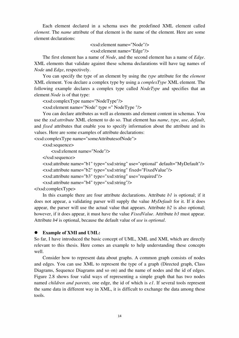
� Example of XMI and UML: So far, I have introduced the basic concept of UML, XML and XMI, which are directly
relevant to this thesis. Here comes an example to help understanding these concepts
well.
Consider how to represent data about graphs. A common graph consists of nodes
and edges. You can use XML to represent the type of a graph (Directed graph, Class
Diagrams, Sequence Diagrams and so on) and the name of nodes and the id of edges.
Figure 2.8 shows four valid ways of representing a simple graph that has two nodes
named children and parents, one edge, the id of which is e1. If several tools represent
the same data in different way in XML, it is difficult to exchange the data among these
tools.
15
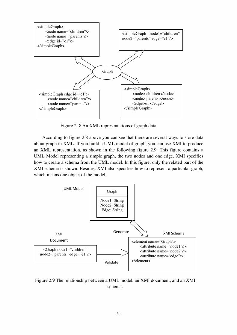
According to figure 2.8 above you can see that there are several ways to store data
about graph in XML. If you build a UML model of graph, you can use XMI to produce
an XML representation, as shown in the following figure 2.9. This figure contains a
UML Model representing a simple graph, the two nodes and one edge. XMI specifies
how to create a schema from the UML model. In this figure, only the related part of the
XMI schema is shown. Besides, XMI also specifies how to represent a particular graph,
which means one object of the model.
<simpleGraph> <node name=”children”/> <node name=”parents”/> <edge id=”e1”/> </simpleGraph>
<simpleGraph node1=”children” node2=”parents” edge=”e1”/>
<simpleGraph edge id=”e1”> <node name=”children”/> <node name=”parents”/> </simpleGraph>
<simpleGraph> <node> children</node> <node> parents </node> <edge>e1 </edge> </simpleGraph>
Graph
Graph
Node1: String Node2: String Edge: String
<Graph node1=”children” node2=”parents” edge=”e1”/>
<element name="Graph"> <attribute name="node1"/> <attribute name="node2"/> <attribute name="edge"/>
</element>
UML Model
XMI
Document
Validate
Generate XMI Schema
Figure 2. 8 An XML representations of graph data
Figure 2.9 The relationship between a UML model, an XMI document, and an XMI
schema.
16
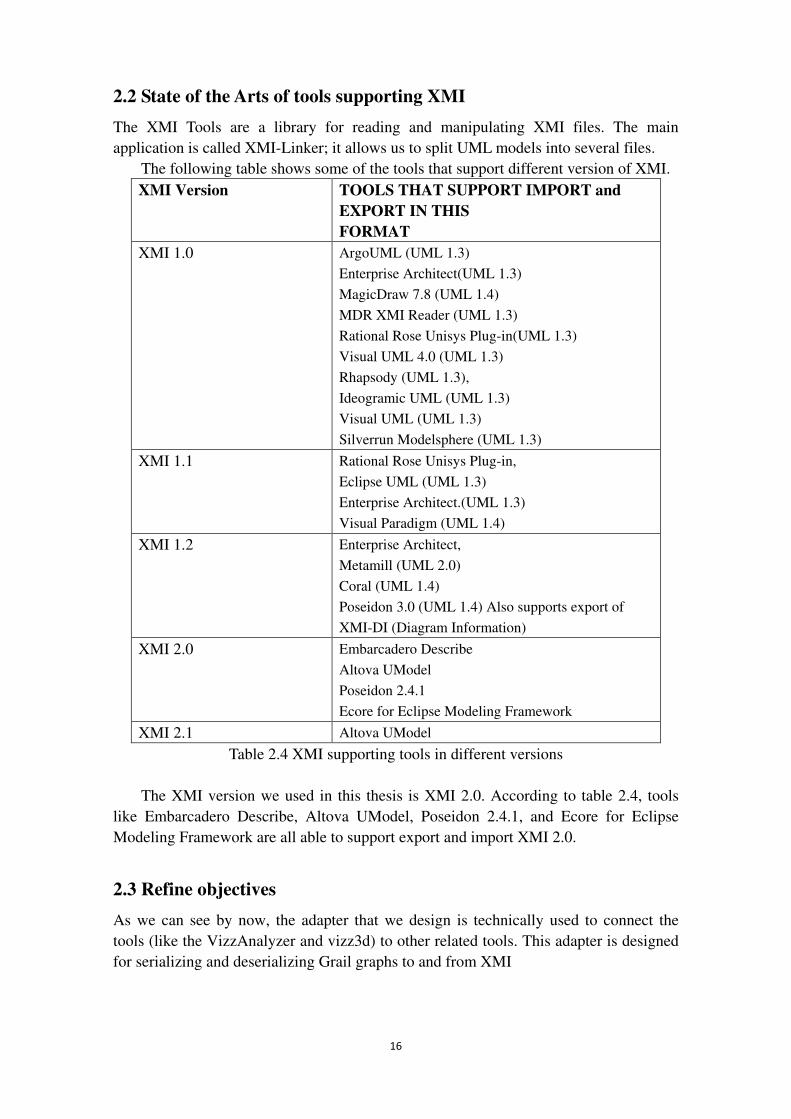
2.2 State of the Arts of tools supporting XMI
The XMI Tools are a library for reading and manipulating XMI files. The main
application is called XMI-Linker; it allows us to split UML models into several files.
The following table shows some of the tools that support different version of XMI.
XMI Version TOOLS THAT SUPPORT IMPORT and EXPORT IN THIS FORMAT
XMI 1.0 ArgoUML (UML 1.3)
Enterprise Architect(UML 1.3)
MagicDraw 7.8 (UML 1.4)
MDR XMI Reader (UML 1.3)
Rational Rose Unisys Plug-in(UML 1.3)
Visual UML 4.0 (UML 1.3)
Rhapsody (UML 1.3),
Ideogramic UML (UML 1.3)
Visual UML (UML 1.3)
Silverrun Modelsphere (UML 1.3)
XMI 1.1 Rational Rose Unisys Plug-in,
Eclipse UML (UML 1.3)
Enterprise Architect.(UML 1.3)
Visual Paradigm (UML 1.4)
XMI 1.2 Enterprise Architect,
Metamill (UML 2.0)
Coral (UML 1.4)
Poseidon 3.0 (UML 1.4) Also supports export of
XMI-DI (Diagram Information)
XMI 2.0 Embarcadero Describe
Altova UModel
Poseidon 2.4.1
Ecore for Eclipse Modeling Framework
XMI 2.1 Altova UModel
Table 2.4 XMI supporting tools in different versions
The XMI version we used in this thesis is XMI 2.0. According to table 2.4, tools
like Embarcadero Describe, Altova UModel, Poseidon 2.4.1, and Ecore for Eclipse
Modeling Framework are all able to support export and import XMI 2.0.
2.3 Refine objectives
As we can see by now, the adapter that we design is technically used to connect the
tools (like the VizzAnalyzer and vizz3d) to other related tools. This adapter is designed
for serializing and deserializing Grail graphs to and from XMI
17
XMI (XML Metadata Interchange) provides a convenient interchange of
metadata between modeling tools, which using UML as their modeling language, and
metadata repositories (OMG MOF based) in distributed heterogeneous environments.
Because XMI has the ability to represent various forms of object-oriented
information, when it comes to lightweight integration among Java applications, Web,
XML, and different kinds of models, software that supports XMI can be used to do this
job.
There exist some other benefits of XMI, here is the list, and these are from [1]:
1. XMI is based on XML technologies, and make up for the drawback of XML.
2. XMI enables you to use modeling with XML.
3. Software that supports XMI creates schemas from models.
4. Software that supports XMI provides a higher level of abstraction than XML
elements and attributes.
5. XMI helps you produce XML documents that can be easily exchanged.
6. XMI enables you to create simple documents and make more advanced ones as
your application evolves.
7. XMI enables you to tailor the XML representation of your objects and
document your choices in your models.
8. XMI enables you to work with data and meta data.
The benefits of XMI stated above, and the basic functionality and the purpose of
this adapter we are designing, and several features of XMI explained in previous
sections, all of them indicate that generality of this project is the most important
objective which we should pay more attention to.
In addition, the final integrated converter should be able to handle different formats
(XMI, GXL and SQL). Taking grail as the intermediate, any two of these three formats
can interchange between each other. The grail will stay the same as original. So the
generality is very important.
2.4 Terminology
� XMI (XML Metadata Interchange) The XML Metadata Interchange (XMI) is an OMG standard for exchanging metadata
information via Extensible Markup Language (XML). The main intention of XMI is to
make metadata interchange between modeling tools (based on the OMG UML) and
between tools and metadata repositories (based on OMG MOF) in distributed
heterogeneous environments be easy. XMI integrates three key industry standards, see
[11]:
1. XML - eXtensible Markup Language, a W3C standard;
2. UML - Unified Modeling Language, an OMG modeling standard;
3. MOF - Meta Object Facility and OMG modeling and metadata repository
standard.
� UML (Unified Modeling Language) In the realm of software engineering, the Unified Modeling Language (UML) is a
standardized specification language for object modeling. UML is a general-purpose
18
modeling language that includes a graphical notation used to create an abstract model of
a system, referred to as a UML model.
UML is officially defined at the Object Management Group (OMG) by the UML
metamodel, a Meta-Object Facility metamodel (MOF). Like other MOF-based
specifications, the UML metamodel and UML models may be serialized in XMI. UML
was designed to specify, visualize, construct, and document software-intensive systems.
� MOF (Meta-Object Facility) The Meta-Object Facility (MOF) is an Object Management Group (OMG) standard
for Model Driven Engineering (MDE). MOF (Meta-Object Facility) is a meta-language,
which means that it is a language to describe languages, including UML. MOF looks
like a simplified UML. The nice thing with this is that it is simple to translate an UML
model into a MOF meta-model.
� OMG (Object Management Group) Object Management Group (OMG) is a consortium, originally aimed at setting
standards for distributed object-oriented systems, and is now focused on modeling
(programs, systems and business processes) and model-based standards. Founded in
1989 by eleven companies (including Hewlett-Packard, IBM, Sun Microsystems, Apple
Computer, American Airlines and Data General), OMG tried to create a heterogeneous
distributed object standard. The goal was a common portable and interoperable object
model with methods and data that work using all types of development environments on
all types of platforms. See [12].
� W3C(World Wide Web Consortium) The World Wide Web Consortium (W3C) is the main international standards
organization for the World Wide Web (abbreviated WWW or W3).
� DOM DOM is an abbreviation for Document Object Model. It is an API used for accessing
XML document. It is also a model used for representing the content of XML document.
It takes XML document as a series relationship among nodes, and also takes every node
as an object. That’s why it is called Document Object Model. See [13], you will find
more information about DOM.
� SAX SAX is the Simple API for XML, originally a Java-only API. It is a serial access parser
API for XML. SAX was the first widely adopted API for XML in Java. SAX provides a
mechanism for reading data from an XML document. It is another popular choice apart
from the Document Object Model (DOM). If you need more materials about SAX, here
is a web site about SAX, see [14].
� MDA MDA is the Model Driven Architecture, it is the software develop framework defined
by OMG. MDA is the framework which is based on UML and other industry standard.
19
It supports software design and the visualization of model, the storage and interchange
of model. The main point of MDA is that the model plays an important role in software
develops. See [15] to get URL about MDA.
� Reverse engineering Reverse engineering (RE) is the process of researching the technological principles of
a device, object or system in the way of analysis of its structure, function and operation.
Reverse engineering, in order to copy or enhance the object, is parsing an object to
see how it works. The practice is now often used on computer hardware and software.
“Software reverse engineering involves reversing a program's machine code back into
the source code that it was written in, using program language statements”. Software
reverse engineering is done to retrieve the source code of a program. Please see [16] for
more information.
2.5 Other Related works
In the field of the current problem, there are some other similar works as what the thesis
deal with. Here, we want to give a brief introduction about other related works. Firstly,
Grail to GXL (Graph eXchange Language) and back, which can be considered as
the most similar work comparing to my problem, is introduced. GXL (Graph eXchange
Language) is designed to be a standard exchange format for graphs. GXL is an XML sublanguage and the syntax is given by a XML DTD (Document Type Definition).
This exchange format offers an adaptable and flexible means to support interoperability
between graph-based tools. As you can see in the first chapter, my problem is
serializing Grail graphs to XMI and vice versa. So we can figure out that the only
difference between these two works is format (GXL and XMI). I am supposed to handle
the conversion between Grail and XMI. For Grail to GXL and back, the exchange
between Grail and GXL should be dealt with. Both formats of GXL and XMI are based
on XML. Both are used to convert grail graphs to a specified format.
Secondly, Grail to SQL (Structured Query Language) and back should be
mentioned. It is also very similar to my work, although SQL is not XML-based. SQL
has its own syntax, which shows a big difference from XMI or GXL. But, on the other
hand, the relationship between XMI and SQL is built by Grail graphs, which also can be
considered as the intermediate product.
Finally, if we integrate these three converters (XMI, GXL and SQL) into one, we
can convert grail graphs to any one of these three formats by using our integrated
converter.
20
3. Analysis and Design In this chapter, some APIs (Application Program Interface) that support XMI are
introduced, and how to represent simple objects and their parts using XMI are explained.
In addition, I will make an analysis of this project, and explain the steps of how to
create XMI document from grail graph and vice versa.
3.1 Basic ideas about writing Objects using XMI
This section describes how to write objects and their parts in an XMI document.
a) Objects The objects with no attributes and references are the simplest objects to write.
There are two alternatives for writing such simple objects. The first optional is
putting them in XMI documents, where all the XML elements in the document follow
the XMI specification. The second optional is writing them inside any XML element. In
the second choice, you could have a single XML document that contains XML elements;
these XML elements are not relevant to the XMI specification as well as objects
represented using XMI. But in both choices, XMI namespace, which is the context for
all the XML elements and attributes defined in the XMI specification, should be used.
The URI (Uniform Resource Identifier) of XMI namespace is http://www.omg.org/XMI.
Generally, we use the namespaces prefix xmi, but of course one can use any namespace
prefix as you wish to use in the XMI documents.
b) XMI document In the beginning of XMI document, you should add the XML PI (Processing
Instruction), because XMI documents are actually XML documents. The PI (processing
instruction) includes the version of XML and identifies the encoding of the characters in
the document. The content of PI describes as follows:
<? xml version="1.0" encoding="UTF-8"?>
Putting the objects in the XMI XML element, which is the root element for an XML
document, is one way to store the objects in an XMI document. There is an XML
attribute of XMI XML element called version, this XML attribute (version) must have a
value that is used to specify which XMI version you want to use. In this thesis, I use the
2.0 version. And the namespace prefix xmi for the XMI namespace must be used in that
attribute version. An empty XMI document describes as follows:
< xmi:XMI xmi:version="2.0" xmlns:xmi="http://www.omg.org/XMI"/>
XMI represents each object in the way of using an XML element. “The tag name
of the element corresponds to the name of the class that the object is an instance of. You
may use XML namespaces to distinguish classes with the same names. Since your class
name may not be a legal XML tag name, you may need to convert from the class name
to a legal XML tag name.” Please look up [1] in detail.
Here is how an object that is an instance of a Graph class can be represented in XMI:
<xmi:XMI xmi:version="2.0" xmlns:xmi="http://www.omg.org/XMI">
<Graph/>
21
</xmi:XMI >
There are several other ways to write objects in XMI document, I will not explain it one
by one here.
c) Object identity The representation of an object consists of its attribute values and references. Two
objects with the same attribute values and references are considered the same object.
With three XML attributes defined by XMI, which will be discussed in the following
paragraph, XMI enables you to specify the identity of an object, not using the object’s
state. Each attribute represents different meanings of the object. Described in the
following:
The id XML attribute has the type ID, so its value must be a legal identifier for an
XML element. The value of the id attribute must be unique within a document, but it
cannot say that will be unique among different documents for sure.
The uuid(universally unique identifier) XML attribute is different from id XML
attribute. The difference between uuid and id describes as following: uuid must contain
a globally unique identifier; it is unique among all objects wherever the object is saved
in different documents; but for id XML attribute, it is unique only in one XMI
document, it maybe not unique among several documents. The name uuid is an
abbreviation for universally unique identifier. The format of the uuid is not specified, so
you can use any value you want.
The label XML attribute represents any other information that you want to denote
for an object. The value of this attribute is not defined by XMI, so it is legal for two
objects to have the same value for this attribute.
When using those attributes are in a document, the namespace prefix for the XMI
namespace must be included in the names of these XML attributes, like xmi:id,
xmi:uuid, xmi:label. All of these attributes are optional, so you can choose which
attribute to use for your applications. Here come some examples of instances of a Node
class that use these attributes:
<xmi:XMI xmi:version="2.0" xmlns:xmi="http://www.omg.org/XMI"/>
< Node xmi:id="_1" xmi:uuid="123" xmi:label=" parent "/>
< Node xmi:id="_2" xmi:label="parent "/>
< Node xmi:id="_3"/>
</xmi:XMI>
In this example, since the first Node object has a uuid attribute with the value 123,
no other Node object should have the same uuid attribute value in any other documents.
It is legal for two objects Node to have the same value parent for this attribute
xmi:label.
d) APIs used to access XMI document Since XMI is built on XML, when it comes to create and read XMI document, we can
use the standard APIs of XML, like DOM and SAX. If there exist new technologies to
create and read the files with XML format, we can use those technologies to deal with
XMI document. Despite those two APIs (DOM and SAX) provide a lot convenience to
parse XML files, when using them to deal with XMI files, it requires to know and
22
understand how XMI files are structured.
Those APIs (DOM and SAX) are not designed particularly for XMI documents,
now we pay attention to APIs that are designed specifically for XMI. One example of
such an API is the Java Object Bridge (JOB), which enables you to store any Java
objects in an XMI document and restore them from an XMI document. Another API
that supports XMI is the XMI Framework. The Framework provides a generic
representation of objects and their states in a simple object model. It enables you to
create XMI documents from generic objects and to make generic objects when reading
XMI documents.
In this thesis, when serializing, I use XMI Framework to write object to XMI
document. While deserializing, the API DOM is used to parse the XMI document.
3.2 Analyses steps from Grail to XMI and back
Before we can store the information that is read in the graph into a XMI document, we
should get all the data out from a graph, and store the data into a temporary file or map
to XMI directly. In this thesis, we did not use a temporary file. We use XMI file to store
nodes and edges directly. If using temporary file, we should know how the data (nodes
and edges) are stored, how we can read the graph information again from this temporary
file, and store the data into a document with a specified format, like XMI document,
then revert the data which is stored in a XMI document into the original graph again,
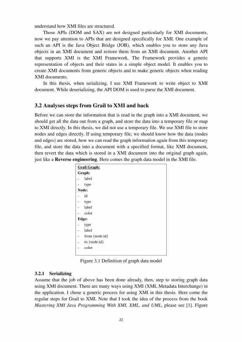
just like a Reverse engineering. Here comes the graph data model in the XMI file.
Grail Graph:
Graph:
- label
- type
Node:
- id
- type
- label
- color
Edge:
- type
- label
- from {node.id}
- to {node.id}
- color
Figure 3.1 Definition of graph data model
3.2.1 Serializing Assume that the job of above has been done already, then, step to storing graph data
using XMI document. There are many ways using XMI (XML Metadata Interchange) in
the application. I chose a generic process for using XMI in this thesis. Here come the
regular steps for Grail to XMI. Note that I took the idea of the process from the book
Mastering XMI Java Programming With XMI, XML, and UML, please see [1]. Figure
23
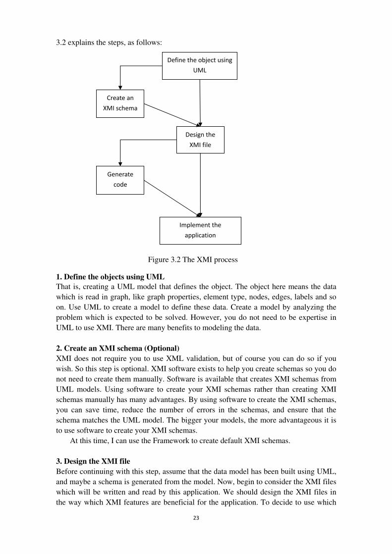
3.2 explains the steps, as follows:
Figure 3.2 The XMI process
1. Define the objects using UML That is, creating a UML model that defines the object. The object here means the data
which is read in graph, like graph properties, element type, nodes, edges, labels and so
on. Use UML to create a model to define these data. Create a model by analyzing the
problem which is expected to be solved. However, you do not need to be expertise in
UML to use XMI. There are many benefits to modeling the data.
2. Create an XMI schema (Optional) XMI does not require you to use XML validation, but of course you can do so if you
wish. So this step is optional. XMI software exists to help you create schemas so you do
not need to create them manually. Software is available that creates XMI schemas from
UML models. Using software to create your XMI schemas rather than creating XMI
schemas manually has many advantages. By using software to create the XMI schemas,
you can save time, reduce the number of errors in the schemas, and ensure that the
schema matches the UML model. The bigger your models, the more advantageous it is
to use software to create your XMI schemas.
At this time, I can use the Framework to create default XMI schemas.
3. Design the XMI file Before continuing with this step, assume that the data model has been built using UML,
and maybe a schema is generated from the model. Now, begin to consider the XMI files
which will be written and read by this application. We should design the XMI files in
the way which XMI features are beneficial for the application. To decide to use which
Define the object using
UML
Create an
XMI schema
Design the
XMI file
Generate
code
Implement the
application
Figure 3.2 The XMI process
24
features of XMI, we should consider how the XMI document are likely to be used. E.g.
the XMI document designed only for our own software, or our own software will use
XMI document produced by other software. Considering this kind of situation will help
to decide which feature of XMI can be used in your XMI document.
4. Generate the code from model (Optional) Assume that the UML model of the graph data is created, possibly an XMI schema is
created too, and the basic content of the XMI document is decided. Now we can
implement the idea using a specified programming language (Java is used in this project)
to deal with or parse the XMI document. However, if it is possible to generate some of
the code you need from the model, then you do not have to implement it yourself. There
are several advantages for doing so, for instance, your code will match your model
specially, which will be more efficient than code that matched several models.
5. Implement the application Although the code may be generated from model in step 4 automatically, there still
probably exists at least part of your software that you should implement by yourself. For
example, the generated code might provide interfaces that you need to implement
yourself, or it might create empty method bodies that you need to write yourself. You
need to decide what to implement yourself and what software to use that supports XMI
or XML.
3.2.2 Deserializing After creating the XMI document for the grail graph, the next task we should do is to parse the XMI document and translate those information into corresponding grail graph. To deal with XMI document, we need the API which can help us to access the XMI document and read the content out of the XMI document. Here are several APIs.
Since XMI is built on XML, as I mentioned above, when it comes to parse XMI
document, we can use the standard APIs of XML, like DOM and SAX. Those two APIs
(DOM and SAX) provide a lot convenience to parse XML files.
Here are another two APIs designed for XMI particularly. One example is Java
Object Bridge (JOB), which enables you to store any Java objects in an XMI document
and restore them from an XMI document. The other API that supports XMI is the XMI
Framework. Just like JOB, the XMI Framework provides interfaces that help you to
deal with XMI documents. The Framework is more complicated than JOB though,
because it provides more complicated capabilities.
I chose DOM to access the XMI document, and read all the attributes of nodes and
edges from the XMI document to build the grail graph again. An example will be given
in the following chapter.
3.3 Conclusion
Note that according to the XMI specification, it does not require you to follow a
particular process stated above for your XMI projects; however, by following the
process provided in this chapter, you can take advantage of the benefits that XMI
provides.
25
4. Implementation This chapter gives a demo implementation of this project. You will see how the converter works. From this chapter, you will understand the whole project Grail to XMI
and back more deeply. In the end, a test case is implemented to prove that our solution is correct.
4.1 A demo implementation
Firstly, I create a graph by loading a GML (Geography Markup Language) file using the
methods provided by Grail.
GraphLoadSave gls = new GraphLoadSave();
GraphInterface g = gls.load("two_parts.gml");
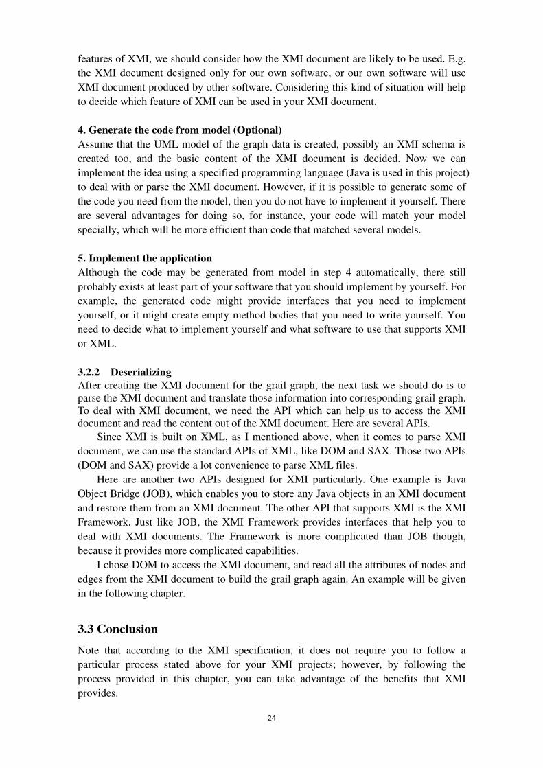
GML files are used as auxiliary files, so that we can visualize the original GML
graph and the final GML graph using the tool yEd, and then compare them to see
whether they are the same. The layout of the original graph is shown in Figure 4.1,
which is displayed by yEd. “yEd is a very powerful graph editor that is written
entirely in the Java programming language. It can be used to quickly and effectively
generate drawings and to apply automatic layouts to a range of different diagrams and
networks.” See [17]
Figure 4.1 Layout of a demo graph visualized in yEd
4.1.1 Flow or progress of my implementation
26
XMI Grail Grail
GML GML
XMI Schema
Validate Generate
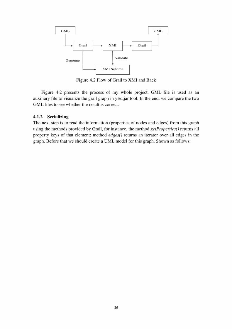
Figure 4.2 Flow of Grail to XMI and Back
Figure 4.2 presents the process of my whole project. GML file is used as an
auxiliary file to visualize the grail graph in yEd.jar tool. In the end, we compare the two
GML files to see whether the result is correct.
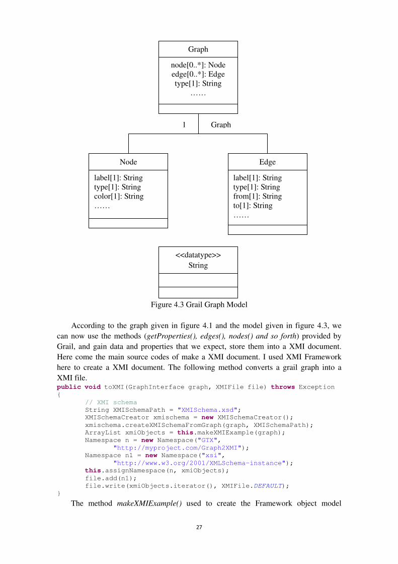
4.1.2 Serializing The next step is to read the information (properties of nodes and edges) from this graph
using the methods provided by Grail, for instance, the method getProperties() returns all
property keys of that element; method edges() returns an iterator over all edges in the
graph. Before that we should create a UML model for this graph. Shown as follows:
27
Graph
node[0..*]: Node edge[0..*]: Edge type[1]: String
……
Node
label[1]: String type[1]: String color[1]: String ……
Edge
label[1]: String type[1]: String from[1]: String to[1]: String ……
<<datatype>>
String
1 Graph
Figure 4.3 Grail Graph Model
According to the graph given in figure 4.1 and the model given in figure 4.3, we
can now use the methods (getProperties(), edges(), nodes() and so forth) provided by
Grail, and gain data and properties that we expect, store them into a XMI document.
Here come the main source codes of make a XMI document. I used XMI Framework
here to create a XMI document. The following method converts a grail graph into a
XMI file. public void toXMI(GraphInterface graph, XMIFile file) throws Exception
{
// XMI schema
String XMISchemaPath = "XMISchema.xsd";
XMISchemaCreator xmischema = new XMISchemaCreator();
xmischema.createXMISchemaFromGraph(graph, XMISchemaPath);
ArrayList xmiObjects = this.makeXMIExample(graph);
Namespace n = new Namespace("GTX",
"http://myproject.com/Graph2XMI");
Namespace n1 = new Namespace("xsi",
"http://www.w3.org/2001/XMLSchema-instance");
this.assignNamespace(n, xmiObjects);
file.add(n1);
file.write(xmiObjects.iterator(), XMIFile.DEFAULT);
} The method makeXMIExample() used to create the Framework object model
28
representation of our grail graph objects. It returns an ArrayList of XMIObjects (like
graph, node, and edge). The source code of this method is shown in Appendix section.
As you read through makeXMIExample(), notice that the method to add an attribute
value to an object, addXMIValue(), has three parameters:
1. The XMI name of the attribute value or reference.
2. The value of the attribute value or reference.
3. The kind of Value it is in the Framework (such as Value.DATA or
Value.REFERENCE, or Value.OBJECT)
Each attribute value or reference is then added to the Framework object that the
addXMIValue() method is invoked on. For example, to represent the attribute value for
the Label attribute of the Node object, a data value is created; its XMI name is Label
and its value is node1. We indicate that this attribute value is a data value by specifying
Value.DATA as the third parameter to the addXMIValue() method. The method
invocation to do this appears as follows:
node.addXMIValue ("Label","node1",Value.DATA);
This adds a data value to the XMIObject representing an instance of the Node class.
Table 4.1 summarizes how the behavior of the addXMIValue() method varies with the
different values that can be used for the third parameter.
THIRD PARAMETER CORRESPONDING FRAMEWORK
INTERFACE
Value.DATA DataValue
Value.OBJECT ObjectValue
Value.REFERENCE Reference
Table 4.1 addXMIValue() Behavior
The XMI document with graph information stored in is given in the Appendix
section. When serializing, XMI schema is created from grail graph simultaneously. I use
the Framework to create default XMI schemas. The source code of creating a XMI
schema is given in Appendix.
The XMISchema class in the Framework represents an XMI schema. You specify a
filename when you create an XMISchema object, and then you invoke the write()
method to create a schema. See the following source code.
29
public void createXMISchemaFromGraph(GraphInterface g, String
XMISchemaPath) {
Model m;
Namespace n = new Namespace("GTX",
"http://myproject.com/Graph2XMI");
try {
m = makeGraphModel(g);
this.addNamespace(n, m);
XMISchema schema = new XMISchema(XMISchemaPath);
schema.setTargetNamespace(n);
schema.write(m.getDeclarations().iterator());
} catch (Exception e) {
e.printStackTrace();
}
}
The method makeGraphModel() will be shown in the Appendix Section. Refer to [1]
for more details about how to create an XMI Framework model. The parameter for the
write() method is an Iterator for the declarations in the model (classes, features, and
packages in a model are called declarations in the Framework). Notice that the target
namespace of the XMISchema is set before writing the schema because the current
version of the Framework requires it to be set.
The addNamespace() method assigns the given namespace to each declaration in
the given graph model:
// Adds the given Namespace to the declarations in the given Model.
public void addNamespace(Namespace n, Model m) throws Exception {
Iterator decls = m.getDeclarations().iterator();
while (decls.hasNext()) {
Data decl = (Data) decls.next();
decl.setXMINamespace(n);
}
}
Refer to the appendix section for more source codes about how to create a XMI
schema.
4.1.3 Deserializing When deserializing, DOM is used to parse the XMI document to get the data stored in it,
and then use these data to create a graph again in Grail. Here comes main part of the
source codes.
30
if (object.getNodeName().toLowerCase().equals("gtx:graph")) {
NamedNodeMap attribs = object.getAttributes();
for (int j = 0; j < attribs.getLength(); ++j) {
addProperty(g, attribs.item(j).getNodeName(), attribs.item(j)
.getNodeValue());
}
}
The codes above add all graph attributes listed in XMI document into grail. The
method setProperty(GraphProperties key, Object value) is used to add properties
(including node properties and edge properties).
if (object.getNodeName().toLowerCase().equals("node")) {
NamedNodeMap attribs = object.getAttributes();
NodeInterface node = null;
for (int j = 0; j < attribs.getLength(); ++j) {
if (attribs.item(j).getNodeName().toLowerCase()
.equals("xmi:id")) {
node = addNode(g, attribs.item(j).getNodeValue());
}
}
}
The codes above add nodes (addNode(g, attribs.item(j).getNodeValue())) and some
integrant attributes of them, which are read from the XMI document, into a Empty
Graph created by Grail.
if (object.getNodeName().toLowerCase().equals("edge")) {
NamedNodeMap attribs = object.getAttributes();
String from = null;
String to = null;
for (int j = 0; j < attribs.getLength(); ++j) {
if (attribs.item(j).getNodeName().toLowerCase().equals("from"))
{
from = attribs.item(j).getNodeValue();
}
if (attribs.item(j).getNodeName().toLowerCase().equals("to")) {
to = attribs.item(j).getNodeValue();
}
}
EdgeInterface ie = addEdge(g, from, to);
}
The codes above add edges (addEdge(g, from, to)) and some integrant attributes of
them, which are read from the XMI document, into grail graph.
Then save the grail graph as a GML file using the method public void
saveGML(GraphInterface g, String file, boolean saveViewProperties) provided in the
class GraphLoadSave in Grail. Then visualize the GML file in the tool yEd again to see
whether the graph we get is the same as the original graph. The truth verifies that the
layout of result graph in GML file is the same as the original graph.
31
The integrated source codes of serializing and deserializing are provided in
Appendix.
4.2 Verification
The demo implementation was shown above, but how can we convince the reader that
our solution is correct? Here comes the verification of our solution.
In this part, we use JUnit to test our code. Firstly, we use our XMI converter to deal
with a grail graph, so we get two grail graphs, one is the original graph; the other is final
graph. Next, we are supposed to compare nodes, edges, and the properties of them of
these two graphs. If all of them are equal to each other, our solution proves to be
correct.
The main two methods used to compare these two graphs are assertEquals (Object
expected, Object actual) and assertTrue (boolean condition). The Objects here can be
the node number or edge number of the two graphs. Here is an example. assertEquals(originalGraph.nodeCount(),finalGraph.nodeCount());
assertEquals(originalGraph.edgeCount(),finalGraph.edgeCount());
Besides, we also compare the properties of the two graphs, including the properties
of nodes and edges, and the value of these properties. As follows: TypeValues a = (TypeValues) dg.getProperty(GraphProperties.TYPE);
TypeValues b = (TypeValues) newDg.getProperty(GraphProperties.TYPE);
boolean what = a.equals(b);
Assert.assertTrue(what);
String label1 = (String) dg.getProperty(GraphProperties.LABEL);
String label2 = (String) newDg.getProperty(GraphProperties.LABEL);
Assert.assertTrue(label1.equals(label2));
In this example, properties Label and Type of the two graphs are compared
respectively. The method assertTrue (boolean condition) is used.
But because of the restriction we mentioned in chapter one (the name of some
properties of the two graphs may be not the same), not every property of the two graphs
is compared.
Using present test cases, the correctness of our solution is verified. But we will add
more detailed test code to test our XMI converter in future work.
32
5. Conclusion and Future Work In this chapter, I will make a brief conclusion about what I did in this thesis, and what
the future job I need to do.
5.1 Conclusion
As I put forward in chapter 1, the problem of the thesis was:
Design an adapter used for serializing and deserializing Grail graphs to and from XMI,
in order to connect the tools (VizzAnalyzer and vizz3d) to others.
Briefly speaking, the problem can be divided into two parts: Serializing and
De-serializing. When serializing, this adapter should be able to recognize a Grail graph
(we call it original graph), and gather all the information of that graph; for instance,
nodes, edges and their attributes. The adapter can store these data into an XMI
document represented in XML syntax. Meanwhile, an XMI schema is created to
validate the XMI document. When de-serializing, the adapter can access an XMI
document, and rebuild a grail graph (we call it final graph) accoding to the data stored
in the XMI document.
To solve this problem, we created a grail graph first by loading a GML file. When
serializing (see section 4.1.2), we implemented the method (toXMI(GraphInterface
graph, XMIFile file )) to convert grail graph into a XMI file. Meanwhile, we
implemented a class XMISchemaCreator to create an XMI schema. Then we went to the
deserializing step (see section 4.1.3), we loaded the XMI file again, and called the
function (from(Reader reader)) to rebuild the grail graph. Then we saved this graph as a
GML file. As you can see in chapter 4, the original graph and the result graph are the
same. In the end, we implemented a test to verify the correctness of our solution. So my
project is completed.
By reading criteria, we know that generality, modulization and extensibility are the
criteria of our project.
The criteria generality was mentioned in the goal refinement. In addition, we were
supposed to implement an interface called Converter in this project. This interface is
provided to users, the users do not have to know how it is implemented inside. So
modulization was reflected by this feature. Plus, as I mentioned in chapter one, our
project can be updated easily. It is easy for the developer to add new performance to the
tools, according to different types of graphs. And other converters, like GXL converter
and SQL converter, can be integrated with XMI converter conveniently. So extensibility
becomes measurable.
However, not all the tasks of this project were completed perfectly. This will be
discussed in the following section.
5.2 Future Work
From restriction, we knew that which idea of the problem we could not follow due to
some reasonable factors.
Because of the restricted time, and other reasonable factors, the solution only
33
accepts the graphs created by Grail, for other graphs, it does not work well. Besides, it
can only convert the grail graph to XMI document. In other words, it does not support
other formats (like GXL, SQL).
Moreover, we have mentioned a problem about reserved characters in restriction part of chapter 1. This problem will happen, when creating an XMI document. We are supposed to solve this problem in our future work.
For future work, the integrated converter can convert a given grail graph into XMI/GXL/SQL document and vice versa. See the following process for example; the four Grail graphs should be the same.
Grail�XMI �Grail�GXL �Grail� SQL�Grail Finally, the current project costs too much time when it comes to a very large graph.
So increasing the efficiency or performance is very important for future work.
34
Reference
[1] Timothy J. Grose , Gary C. Doney, Stephen A. Brodsky (2002). Mastering XMI,
Java programming with XMI, XML, and UML. John Wiley & Sons, Inc.
[2] Shankar Gopinath (2006). Real-time UML to XMI Conversion. Royal Institute of
Technology.
[3] Daniel Varro, Gergely Varro, Andras Pataricza (2000). Towards an XMI-based
Model Interchange Format for Graph Transformation Systems. Budapest University
of Technology and Economics.
[4] Danny Tramnitzke (2007). Object Call Graph Visualization. Växjö University.
[5] Sara Brockmans, Raphael Volz, Andreas Eberhart, and Peter Löffler (2004). Visual
Modeling of OWL DL Ontologies Using UML. University of Karlsruhe.
[6] XML Metadata Interchange (XMI) Specification.
http://www.omg.org/docs/formal/03-05-02.pdf.
[7] Thomas Panas (2005). A Framework for Reverse Engineering. Växjö University.
[8] Andreas Winter, Bernt Kullbach, and Volker Riediger (2002). An overview of the
GXL Graph Exchange Luaguage. University of Koblenz-Landau.
[9] Cover Pages: XML Metadata Interchange (XMI).
http://xml.coverpages.org/xmi.html.
[10] DotNetJohn. Introducing Unified Modeling Language.
http://www.dotnetjohn.com/articles.aspx?articleid=263.
[11] Wikipedia. XML Metadata Interchange (XMI). http://en.wikipedia.org/wiki/XMI.
[12] Wikipedia. Object Management Group.
http://en.wikipedia.org/wiki/Object_Management_Group.
[13] W3C Document Object Model (DOM). http://www.w3.org/DOM/.
[14] Official website for SAX. http://www.saxproject.org/.
[15] OMG Model Driven Architecture. http://www.omg.org/mda/.
[16] Wikipedia. Reverse engineering. http://en.wikipedia.org/wiki/Reverse_engineering.
[17] yEd-Java Graph Editor. http://www.yworks.com/en/products_yed_about.html.
[18] XML Schema part1: Structures Second Edition.
http://www.w3.org/TR/xmlschema-1/. W3C Recommendation 28 October 2004.
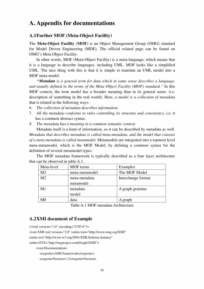
35
A. Appendix for documentations
A.1 Further MOF (Meta-Object Facility)
The Meta-Object Facility (MOF) is an Object Management Group (OMG) standard
for Model Driven Engineering (MDE). The official related page can be found on
OMG’s Meta Object Facility.
In other words, MOF (Meta-Object Facility) is a meta-language, which means that
it is a language to describe languages, including UML. MOF looks like a simplified
UML. The nice thing with this is that it is simple to translate an UML model into a
MOF meta-model.
“Metadata is a general term for data which in some sense describes a language,
and usually defined in the terms of the Meta Object Facility (MOF) standard.” In this
MOF context, the term model has a broader meaning than in its general sense. (i.e.
description of something in the real world). Here, a model is a collection of metadata
that is related in the following ways:
6. The collection of metadata describes information.
7. All the metadata conforms to rules controlling its structure and consistency, i.e. it
has a common abstract syntax.
8. The metadata has a meaning in a common semantic context.
Metadata itself is a kind of information, so it can be described by metadata as well.
Metadata that describes metadata is called meta-metadata, and the model that consists
of a meta-metadata is called metamodel. Metamodels are integrated into a topmost level
meta-metamodel, which is the MOF Model, by defining a common syntax for the
definition of several metamodel types.
The MOF metadata framework is typically described as a four layer architecture
that can be observed in table A.1.
Meta-level MOF terms Examples
M3 meta-metamodel The MOF Model
M2 meta-metadata
metamodel
Interchange format
M1 metadata
model
A graph gramma
M0 data A graph
Table A.1 MOF metadata Architecture
A.2 XMI document of Example
<?xml version="1.0" encoding="UTF-8"?>
<xmi:XMI xmi:version="2.0" xmlns:xmi="http://www.omg.org/XMI"
xmlns:xsi="http://www.w3.org/2001/XMLSchema-instance"
xmlns:GTX="http://myproject.com/Graph2XMI">
<xmi:Documentation>
<exporter>XMI Framework</exporter>
<exporterVersion>1.2</exporterVersion>
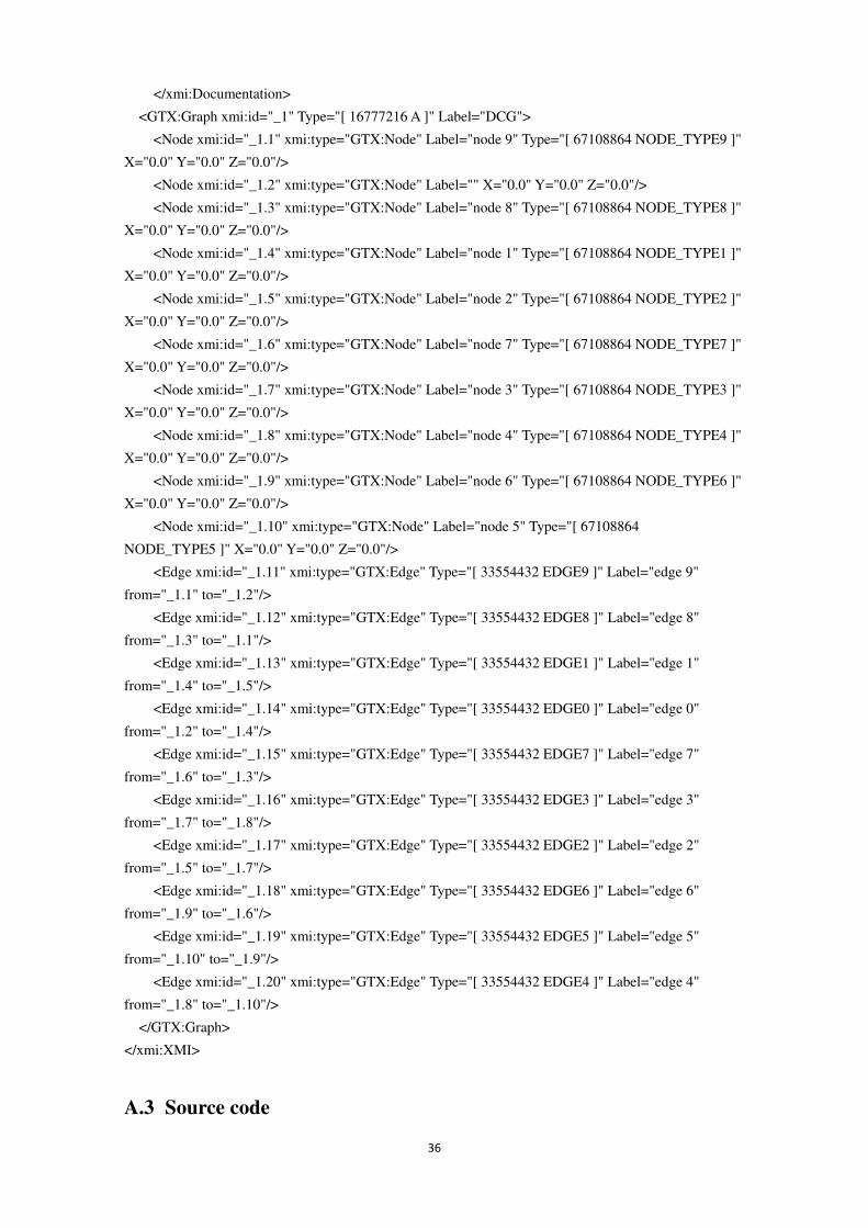
36
</xmi:Documentation>
<GTX:Graph xmi:id="_1" Type="[ 16777216 A ]" Label="DCG">
<Node xmi:id="_1.1" xmi:type="GTX:Node" Label="node 9" Type="[ 67108864 NODE_TYPE9 ]"
X="0.0" Y="0.0" Z="0.0"/>
<Node xmi:id="_1.2" xmi:type="GTX:Node" Label="" X="0.0" Y="0.0" Z="0.0"/>
<Node xmi:id="_1.3" xmi:type="GTX:Node" Label="node 8" Type="[ 67108864 NODE_TYPE8 ]"
X="0.0" Y="0.0" Z="0.0"/>
<Node xmi:id="_1.4" xmi:type="GTX:Node" Label="node 1" Type="[ 67108864 NODE_TYPE1 ]"
X="0.0" Y="0.0" Z="0.0"/>
<Node xmi:id="_1.5" xmi:type="GTX:Node" Label="node 2" Type="[ 67108864 NODE_TYPE2 ]"
X="0.0" Y="0.0" Z="0.0"/>
<Node xmi:id="_1.6" xmi:type="GTX:Node" Label="node 7" Type="[ 67108864 NODE_TYPE7 ]"
X="0.0" Y="0.0" Z="0.0"/>
<Node xmi:id="_1.7" xmi:type="GTX:Node" Label="node 3" Type="[ 67108864 NODE_TYPE3 ]"
X="0.0" Y="0.0" Z="0.0"/>
<Node xmi:id="_1.8" xmi:type="GTX:Node" Label="node 4" Type="[ 67108864 NODE_TYPE4 ]"
X="0.0" Y="0.0" Z="0.0"/>
<Node xmi:id="_1.9" xmi:type="GTX:Node" Label="node 6" Type="[ 67108864 NODE_TYPE6 ]"
X="0.0" Y="0.0" Z="0.0"/>
<Node xmi:id="_1.10" xmi:type="GTX:Node" Label="node 5" Type="[ 67108864
NODE_TYPE5 ]" X="0.0" Y="0.0" Z="0.0"/>
<Edge xmi:id="_1.11" xmi:type="GTX:Edge" Type="[ 33554432 EDGE9 ]" Label="edge 9"
from="_1.1" to="_1.2"/>
<Edge xmi:id="_1.12" xmi:type="GTX:Edge" Type="[ 33554432 EDGE8 ]" Label="edge 8"
from="_1.3" to="_1.1"/>
<Edge xmi:id="_1.13" xmi:type="GTX:Edge" Type="[ 33554432 EDGE1 ]" Label="edge 1"
from="_1.4" to="_1.5"/>
<Edge xmi:id="_1.14" xmi:type="GTX:Edge" Type="[ 33554432 EDGE0 ]" Label="edge 0"
from="_1.2" to="_1.4"/>
<Edge xmi:id="_1.15" xmi:type="GTX:Edge" Type="[ 33554432 EDGE7 ]" Label="edge 7"
from="_1.6" to="_1.3"/>
<Edge xmi:id="_1.16" xmi:type="GTX:Edge" Type="[ 33554432 EDGE3 ]" Label="edge 3"
from="_1.7" to="_1.8"/>
<Edge xmi:id="_1.17" xmi:type="GTX:Edge" Type="[ 33554432 EDGE2 ]" Label="edge 2"
from="_1.5" to="_1.7"/>
<Edge xmi:id="_1.18" xmi:type="GTX:Edge" Type="[ 33554432 EDGE6 ]" Label="edge 6"
from="_1.9" to="_1.6"/>
<Edge xmi:id="_1.19" xmi:type="GTX:Edge" Type="[ 33554432 EDGE5 ]" Label="edge 5"
from="_1.10" to="_1.9"/>
<Edge xmi:id="_1.20" xmi:type="GTX:Edge" Type="[ 33554432 EDGE4 ]" Label="edge 4"
from="_1.8" to="_1.10"/>
</GTX:Graph>
</xmi:XMI>
A.3 Source code
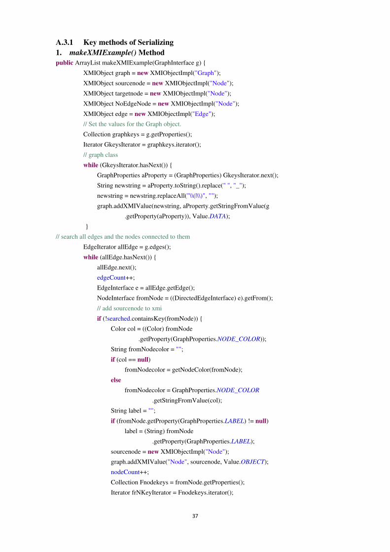
37
A.3.1 Key methods of Serializing 1. makeXMIExample() Method public ArrayList makeXMIExample(GraphInterface g) {
XMIObject graph = new XMIObjectImpl("Graph");
XMIObject sourcenode = new XMIObjectImpl("Node");
XMIObject targetnode = new XMIObjectImpl("Node");
XMIObject NoEdgeNode = new XMIObjectImpl("Node");
XMIObject edge = new XMIObjectImpl("Edge");
// Set the values for the Graph object.
Collection graphkeys = g.getProperties();
Iterator GkeysIterator = graphkeys.iterator();
// graph class
while (GkeysIterator.hasNext()) {
GraphProperties aProperty = (GraphProperties) GkeysIterator.next();
String newstring = aProperty.toString().replace(" ", "_");
newstring = newstring.replaceAll("\\(|\\)", "");
graph.addXMIValue(newstring, aProperty.getStringFromValue(g
.getProperty(aProperty)), Value.DATA);
}
// search all edges and the nodes connected to them
EdgeIterator allEdge = g.edges();
while (allEdge.hasNext()) {
allEdge.next();
edgeCount++;
EdgeInterface e = allEdge.getEdge();
NodeInterface fromNode = ((DirectedEdgeInterface) e).getFrom();
// add sourcenode to xmi
if (!searched.containsKey(fromNode)) {
Color col = ((Color) fromNode
.getProperty(GraphProperties.NODE_COLOR));
String fromNodecolor = "";
if (col == null)
fromNodecolor = getNodeColor(fromNode);
else
fromNodecolor = GraphProperties.NODE_COLOR
.getStringFromValue(col);
String label = "";
if (fromNode.getProperty(GraphProperties.LABEL) != null)
label = (String) fromNode
.getProperty(GraphProperties.LABEL);
sourcenode = new XMIObjectImpl("Node");
graph.addXMIValue("Node", sourcenode, Value.OBJECT);
nodeCount++;
Collection Fnodekeys = fromNode.getProperties();
Iterator frNKeyIterator = Fnodekeys.iterator();
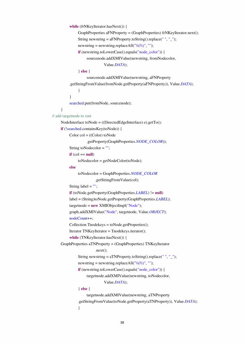
38
while (frNKeyIterator.hasNext()) {
GraphProperties aFNProperty = (GraphProperties) frNKeyIterator.next();
String newstring = aFNProperty.toString().replace(" ", "_");
newstring = newstring.replaceAll("\\(|\\)", "");
if (newstring.toLowerCase().equals("node_color")) {
sourcenode.addXMIValue(newstring, fromNodecolor,
Value.DATA);
} else {
sourcenode.addXMIValue(newstring, aFNProperty
.getStringFromValue(fromNode.getProperty(aFNProperty)), Value.DATA);
}
}
searched.put(fromNode, sourcenode);
}
// add targetnode to xmi
NodeInterface toNode = ((DirectedEdgeInterface) e).getTo();
if (!searched.containsKey(toNode)) {
Color col = ((Color) toNode
.getProperty(GraphProperties.NODE_COLOR));
String toNodecolor = "";
if (col == null)
toNodecolor = getNodeColor(toNode);
else
toNodecolor = GraphProperties.NODE_COLOR
.getStringFromValue(col);
String label = "";
if (toNode.getProperty(GraphProperties.LABEL) != null)
label = (String)toNode.getProperty(GraphProperties.LABEL);
targetnode = new XMIObjectImpl("Node");
graph.addXMIValue("Node", targetnode, Value.OBJECT);
nodeCount++;
Collection Tnodekeys = toNode.getProperties();
Iterator TNKeyIterator = Tnodekeys.iterator();
while (TNKeyIterator.hasNext()) {
GraphProperties aTNProperty = (GraphProperties) TNKeyIterator
.next();
String newstring = aTNProperty.toString().replace(" ", "_");
newstring = newstring.replaceAll("\\(|\\)", "");
if (newstring.toLowerCase().equals("node_color")) {
targetnode.addXMIValue(newstring, toNodecolor,
Value.DATA);
} else {
targetnode.addXMIValue(newstring, aTNProperty
.getStringFromValue(toNode.getProperty(aTNProperty)), Value.DATA);
}
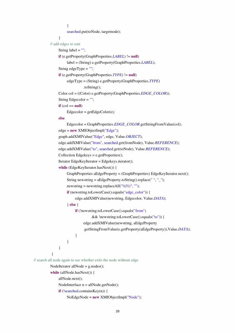
39
}
searched.put(toNode, targetnode);
}
// add edges to xmi
String label = "";
if (e.getProperty(GraphProperties.LABEL) != null)
label = (String) e.getProperty(GraphProperties.LABEL);
String edgeType = "";
if (e.getProperty(GraphProperties.TYPE) != null)
edgeType = (String) e.getProperty(GraphProperties.TYPE)
.toString();
Color col = ((Color) e.getProperty(GraphProperties.EDGE_COLOR));
String Edgecolor = "";
if (col == null)
Edgecolor = getEdgeColor(e);
else
Edgecolor = GraphProperties.EDGE_COLOR.getStringFromValue(col);
edge = new XMIObjectImpl("Edge");
graph.addXMIValue("Edge", edge, Value.OBJECT);
edge.addXMIValue("from", searched.get(fromNode), Value.REFERENCE);
edge.addXMIValue("to", searched.get(toNode), Value.REFERENCE);
Collection Edgekeys = e.getProperties();
Iterator EdgeKeyIterator = Edgekeys.iterator();
while (EdgeKeyIterator.hasNext()) {
GraphProperties aEdgeProperty = (GraphProperties) EdgeKeyIterator.next();
String newstring = aEdgeProperty.toString().replace(" ", "_");
newstring = newstring.replaceAll("\\(|\\)", "");
if (newstring.toLowerCase().equals("edge_color")) {
edge.addXMIValue(newstring, Edgecolor, Value.DATA);
} else {
if (!newstring.toLowerCase().equals("from")
&& !newstring.toLowerCase().equals("to")) {
edge.addXMIValue(newstring, aEdgeProperty
.getStringFromValue(e.getProperty(aEdgeProperty)),Value.DATA);
}
}
}
}
// search all node again to see whether exits the node without edge
NodeIterator allNode = g.nodes();
while (allNode.hasNext()) {
allNode.next();
NodeInterface n = allNode.getNode();
if (!searched.containsKey(n)) {
NoEdgeNode = new XMIObjectImpl("Node");
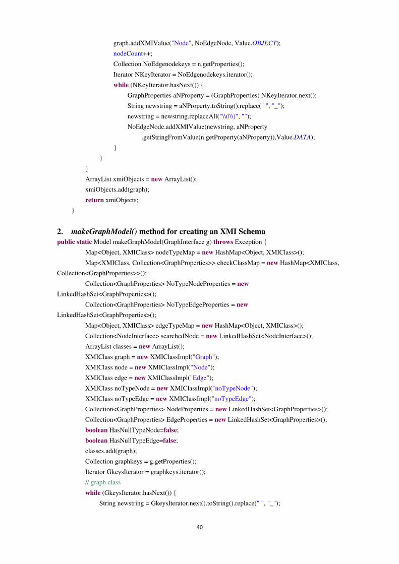
40
graph.addXMIValue("Node", NoEdgeNode, Value.OBJECT);
nodeCount++;
Collection NoEdgenodekeys = n.getProperties();
Iterator NKeyIterator = NoEdgenodekeys.iterator();
while (NKeyIterator.hasNext()) {
GraphProperties aNProperty = (GraphProperties) NKeyIterator.next();
String newstring = aNProperty.toString().replace(" ", "_");
newstring = newstring.replaceAll("\\(|\\)", "");
NoEdgeNode.addXMIValue(newstring, aNProperty
.getStringFromValue(n.getProperty(aNProperty)),Value.DATA);
}
}
}
ArrayList xmiObjects = new ArrayList();
xmiObjects.add(graph);
return xmiObjects;
}
2. makeGraphModel() method for creating an XMI Schema public static Model makeGraphModel(GraphInterface g) throws Exception {
Map<Object, XMIClass> nodeTypeMap = new HashMap<Object, XMIClass>();
Map<XMIClass, Collection<GraphProperties>> checkClassMap = new HashMap<XMIClass,
Collection<GraphProperties>>();
Collection<GraphProperties> NoTypeNodeProperties = new
LinkedHashSet<GraphProperties>();
Collection<GraphProperties> NoTypeEdgeProperties = new
LinkedHashSet<GraphProperties>();
Map<Object, XMIClass> edgeTypeMap = new HashMap<Object, XMIClass>();
Collection<NodeInterface> searchedNode = new LinkedHashSet<NodeInterface>();
ArrayList classes = new ArrayList();
XMIClass graph = new XMIClassImpl("Graph");
XMIClass node = new XMIClassImpl("Node");
XMIClass edge = new XMIClassImpl("Edge");
XMIClass noTypeNode = new XMIClassImpl("noTypeNode");
XMIClass noTypeEdge = new XMIClassImpl("noTypeEdge");
Collection<GraphProperties> NodeProperties = new LinkedHashSet<GraphProperties>();
Collection<GraphProperties> EdgeProperties = new LinkedHashSet<GraphProperties>();
boolean HasNullTypeNode=false;
boolean HasNullTypeEdge=false;
classes.add(graph);
Collection graphkeys = g.getProperties();
Iterator GkeysIterator = graphkeys.iterator();
// graph class
while (GkeysIterator.hasNext()) {
String newstring = GkeysIterator.next().toString().replace(" ", "_");
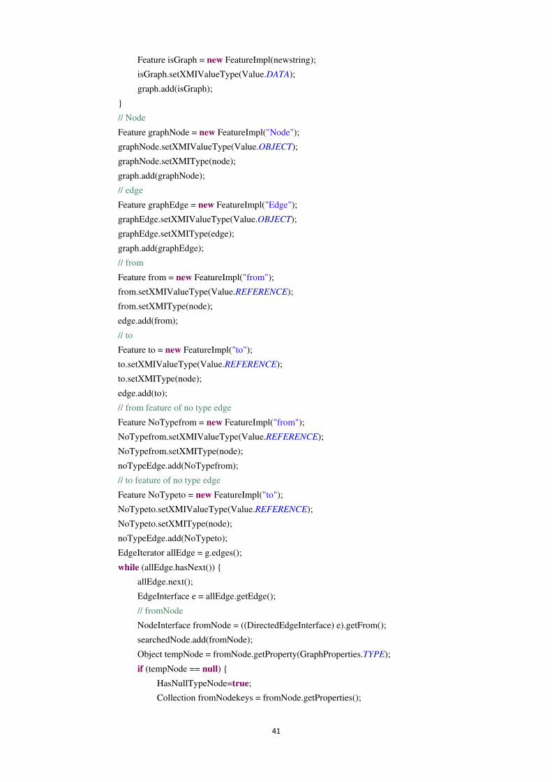
41
Feature isGraph = new FeatureImpl(newstring);
isGraph.setXMIValueType(Value.DATA);
graph.add(isGraph);
}
// Node
Feature graphNode = new FeatureImpl("Node");
graphNode.setXMIValueType(Value.OBJECT);
graphNode.setXMIType(node);
graph.add(graphNode);
// edge
Feature graphEdge = new FeatureImpl("Edge");
graphEdge.setXMIValueType(Value.OBJECT);
graphEdge.setXMIType(edge);
graph.add(graphEdge);
// from
Feature from = new FeatureImpl("from");
from.setXMIValueType(Value.REFERENCE);
from.setXMIType(node);
edge.add(from);
// to
Feature to = new FeatureImpl("to");
to.setXMIValueType(Value.REFERENCE);
to.setXMIType(node);
edge.add(to);
// from feature of no type edge
Feature NoTypefrom = new FeatureImpl("from");
NoTypefrom.setXMIValueType(Value.REFERENCE);
NoTypefrom.setXMIType(node);
noTypeEdge.add(NoTypefrom);
// to feature of no type edge
Feature NoTypeto = new FeatureImpl("to");
NoTypeto.setXMIValueType(Value.REFERENCE);
NoTypeto.setXMIType(node);
noTypeEdge.add(NoTypeto);
EdgeIterator allEdge = g.edges();
while (allEdge.hasNext()) {
allEdge.next();
EdgeInterface e = allEdge.getEdge();
// fromNode
NodeInterface fromNode = ((DirectedEdgeInterface) e).getFrom();
searchedNode.add(fromNode);
Object tempNode = fromNode.getProperty(GraphProperties.TYPE);
if (tempNode == null) {
HasNullTypeNode=true;
Collection fromNodekeys = fromNode.getProperties();
42
Iterator NkeysIterator = fromNodekeys.iterator();
while (NkeysIterator.hasNext()) {
GraphProperties nodeProperty = (GraphProperties) NkeysIterator.next();
String newstring = nodeProperty.toString().replace(" ", "_");
Feature isNode = new FeatureImpl(newstring);
if (!NoTypeNodeProperties.contains(nodeProperty)) {
isNode.setXMIValueType(Value.DATA);
noTypeNode.add(isNode);
NoTypeNodeProperties.add(nodeProperty);
}
}
} else if (nodeTypeMap.containsKey(tempNode)) {
XMIClass tempXMIClass = nodeTypeMap.get(tempNode);
Collection fromNodekeys = fromNode.getProperties();
Iterator NkeysIterator = fromNodekeys.iterator();
while (NkeysIterator.hasNext()) {
GraphProperties nodeProperty = (GraphProperties) NkeysIterator.next();
String newstring = nodeProperty.toString().replace(" ", "_");
Feature isNode = new FeatureImpl(newstring);
if (!checkClassMap.get(tempXMIClass).contains(nodeProperty)) {
isNode.setXMIValueType(Value.DATA);
tempXMIClass.add(isNode);
checkClassMap.get(tempXMIClass).add(nodeProperty);
}
}
}
// find a node with new type
else if (!nodeTypeMap.containsKey(tempNode)) {
Collection<GraphProperties> NewTypeProperties = new
LinkedHashSet<GraphProperties>();
XMIClass node1Class = new XMIClassImpl(tempNode.toString());
classes.add(node1Class);
Collection fromNodekeys = fromNode.getProperties();
Iterator NkeysIterator = fromNodekeys.iterator();
while (NkeysIterator.hasNext()) {
GraphProperties nodeProperty = (GraphProperties) NkeysIterator.next();
String newstring = nodeProperty.toString().replace(" ", "_");
Feature isNode = new FeatureImpl(newstring);
if (!NewTypeProperties.contains(nodeProperty)) {
isNode.setXMIValueType(Value.DATA);
node1Class.add(isNode);
NewTypeProperties.add(nodeProperty);
}
}
checkClassMap.put(node1Class, NewTypeProperties);
43
nodeTypeMap.put(tempNode, node1Class);
}
// all properties of all the fromnode
Collection fromNodekeys = fromNode.getProperties();
Iterator NkeysIterator = fromNodekeys.iterator();
while (NkeysIterator.hasNext()) {
GraphProperties nodeProperty = (GraphProperties) NkeysIterator
.next();
String newstring = nodeProperty.toString().replace(" ", "_");
Feature isNode = new FeatureImpl(newstring);
if (!NodeProperties.contains(nodeProperty)) {
isNode.setXMIValueType(Value.DATA);
node.add(isNode);
NodeProperties.add(nodeProperty);
}
}
//toNode
NodeInterface toNode = ((DirectedEdgeInterface) e).getTo();
searchedNode.add(toNode);
Object tempToNode = toNode.getProperty(GraphProperties.TYPE);
if (tempToNode == null) {
HasNullTypeNode=true;
Collection toNodekeys = toNode.getProperties();
Iterator tokeysIterator = toNodekeys.iterator();
while (tokeysIterator.hasNext()) {
GraphProperties nodeProperty = (GraphProperties) tokeysIterator.next();
String newstring = nodeProperty.toString().replace(" ", "_");
Feature isNode = new FeatureImpl(newstring);
if (!NoTypeNodeProperties.contains(nodeProperty)) {
isNode.setXMIValueType(Value.DATA);
noTypeNode.add(isNode);
NoTypeNodeProperties.add(nodeProperty);
}
}
} else if (nodeTypeMap.containsKey(tempToNode)) {
XMIClass tempXMIClass = nodeTypeMap.get(tempToNode);
Collection toNodekeys = toNode.getProperties();
Iterator tokeysIterator = toNodekeys.iterator();
while (tokeysIterator.hasNext()) {
GraphProperties nodeProperty = (GraphProperties) tokeysIterator.next();
String newstring = nodeProperty.toString().replace(" ", "_");
Feature isNode = new FeatureImpl(newstring);
if (!checkClassMap.get(tempXMIClass).contains(nodeProperty)) {
isNode.setXMIValueType(Value.DATA);
tempXMIClass.add(isNode);
44
checkClassMap.get(tempXMIClass).add(nodeProperty);
}
}
}
// find a node with new type
else if (!nodeTypeMap.containsKey(tempToNode)) {
Collection<GraphProperties> NewTypeProperties = new
LinkedHashSet<GraphProperties>();
XMIClass node1Class = new XMIClassImpl(tempToNode.toString());
classes.add(node1Class);
Collection toNodekeys = toNode.getProperties();
Iterator tokeysIterator = toNodekeys.iterator();
while (tokeysIterator.hasNext()) {
GraphProperties nodeProperty = (GraphProperties) tokeysIterator.next();
String newstring = nodeProperty.toString().replace(" ", "_");
Feature isNode = new FeatureImpl(newstring);
if (!NewTypeProperties.contains(nodeProperty)) {
isNode.setXMIValueType(Value.DATA);
node1Class.add(isNode);
NewTypeProperties.add(nodeProperty);
}
}
checkClassMap.put(node1Class, NewTypeProperties);
nodeTypeMap.put(tempToNode, node1Class);
}
// all properties of all the toNode
Collection ToNodekeys = toNode.getProperties();
Iterator TNkeysIterator = ToNodekeys.iterator();
while (TNkeysIterator.hasNext()) {
GraphProperties TnodeProperty = (GraphProperties) TNkeysIterator.next();
String newstring = TnodeProperty.toString().replace(" ", "_");
Feature isNode = new FeatureImpl(newstring);
if (!NodeProperties.contains(TnodeProperty)) {
isNode.setXMIValueType(Value.DATA);
node.add(isNode);
NodeProperties.add(TnodeProperty);
}
}
// edge
Object tempEdge = e.getProperty(GraphProperties.TYPE);
if (tempEdge == null) {
HasNullTypeEdge=true;
Collection edgekeys = e.getProperties();
Iterator edgekeysIterator = edgekeys.iterator();
while (edgekeysIterator.hasNext()) {
45
GraphProperties edgeProperty = (GraphProperties) edgekeysIterator.next();
String newstring = edgeProperty.toString().replace(" ", "_");
Feature isEdge = new FeatureImpl(newstring);
if (!NoTypeEdgeProperties.contains(edgeProperty)) {
isEdge.setXMIValueType(Value.DATA);
noTypeEdge.add(isEdge);
NoTypeEdgeProperties.add(edgeProperty);
}
}
} else if (edgeTypeMap.containsKey(tempEdge)) {
XMIClass tempXMIClass = edgeTypeMap.get(tempEdge);
Collection edgekeys = e.getProperties();
Iterator keysIterator = edgekeys.iterator();
while (keysIterator.hasNext()) {
GraphProperties edgeProperty = (GraphProperties) keysIterator.next();
String newstring = edgeProperty.toString().replace(" ", "_");
Feature isEdge = new FeatureImpl(newstring);
if (!checkClassMap.get(tempXMIClass).contains(edgeProperty)) {
isEdge.setXMIValueType(Value.DATA);
tempXMIClass.add(isEdge);
checkClassMap.get(tempXMIClass).add(edgeProperty);
}
}
}
// find a edge with new type
else if (!edgeTypeMap.containsKey(tempEdge)) {
Collection<GraphProperties> NewTypeProperties = new
LinkedHashSet<GraphProperties>();
XMIClass edge1Class = new XMIClassImpl(tempEdge.toString());
classes.add(edge1Class);
// from
Feature from1 = new FeatureImpl("from");
from1.setXMIValueType(Value.REFERENCE);
from1.setXMIType(nodeTypeMap.get(((DirectedEdgeInterface) e)
.getFrom().getProperty(GraphProperties.TYPE)));
edge1Class.add(from1);
// to
Feature to1 = new FeatureImpl("to");
to1.setXMIValueType(Value.REFERENCE);
to1.setXMIType(nodeTypeMap.get(((DirectedEdgeInterface) e)
.getTo().getProperty(GraphProperties.TYPE)));
edge1Class.add(to1);
Collection edgekeys = e.getProperties();
Iterator keysIterator = edgekeys.iterator();
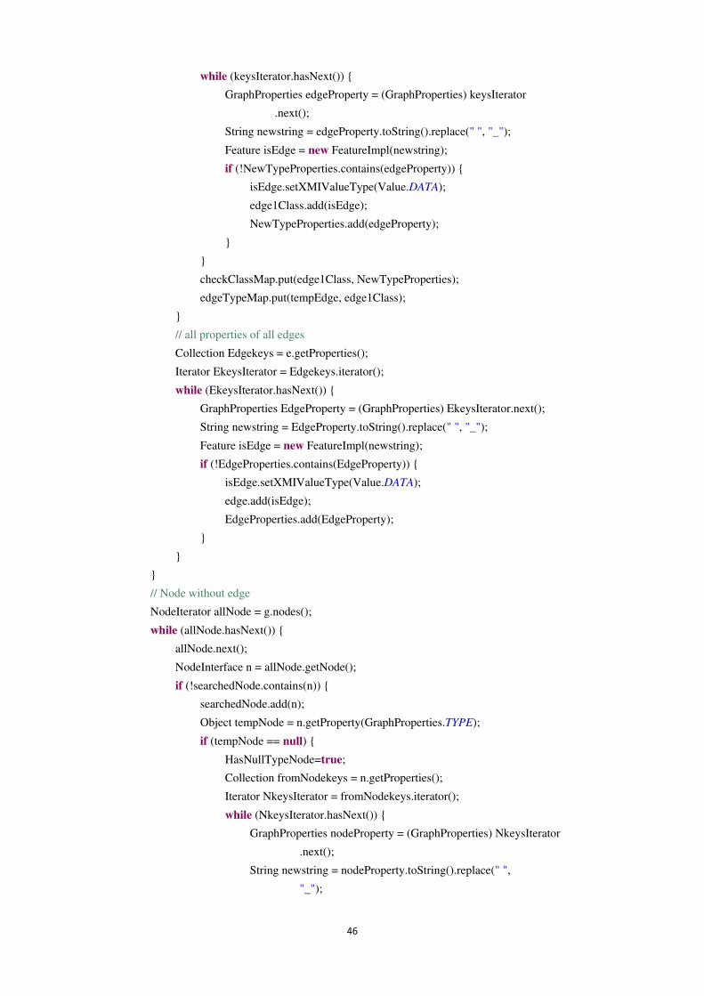
46
while (keysIterator.hasNext()) {
GraphProperties edgeProperty = (GraphProperties) keysIterator
.next();
String newstring = edgeProperty.toString().replace(" ", "_");
Feature isEdge = new FeatureImpl(newstring);
if (!NewTypeProperties.contains(edgeProperty)) {
isEdge.setXMIValueType(Value.DATA);
edge1Class.add(isEdge);
NewTypeProperties.add(edgeProperty);
}
}
checkClassMap.put(edge1Class, NewTypeProperties);
edgeTypeMap.put(tempEdge, edge1Class);
}
// all properties of all edges
Collection Edgekeys = e.getProperties();
Iterator EkeysIterator = Edgekeys.iterator();
while (EkeysIterator.hasNext()) {
GraphProperties EdgeProperty = (GraphProperties) EkeysIterator.next();
String newstring = EdgeProperty.toString().replace(" ", "_");
Feature isEdge = new FeatureImpl(newstring);
if (!EdgeProperties.contains(EdgeProperty)) {
isEdge.setXMIValueType(Value.DATA);
edge.add(isEdge);
EdgeProperties.add(EdgeProperty);
}
}
}
// Node without edge
NodeIterator allNode = g.nodes();
while (allNode.hasNext()) {
allNode.next();
NodeInterface n = allNode.getNode();
if (!searchedNode.contains(n)) {
searchedNode.add(n);
Object tempNode = n.getProperty(GraphProperties.TYPE);
if (tempNode == null) {
HasNullTypeNode=true;
Collection fromNodekeys = n.getProperties();
Iterator NkeysIterator = fromNodekeys.iterator();
while (NkeysIterator.hasNext()) {
GraphProperties nodeProperty = (GraphProperties) NkeysIterator
.next();
String newstring = nodeProperty.toString().replace(" ",
"_");
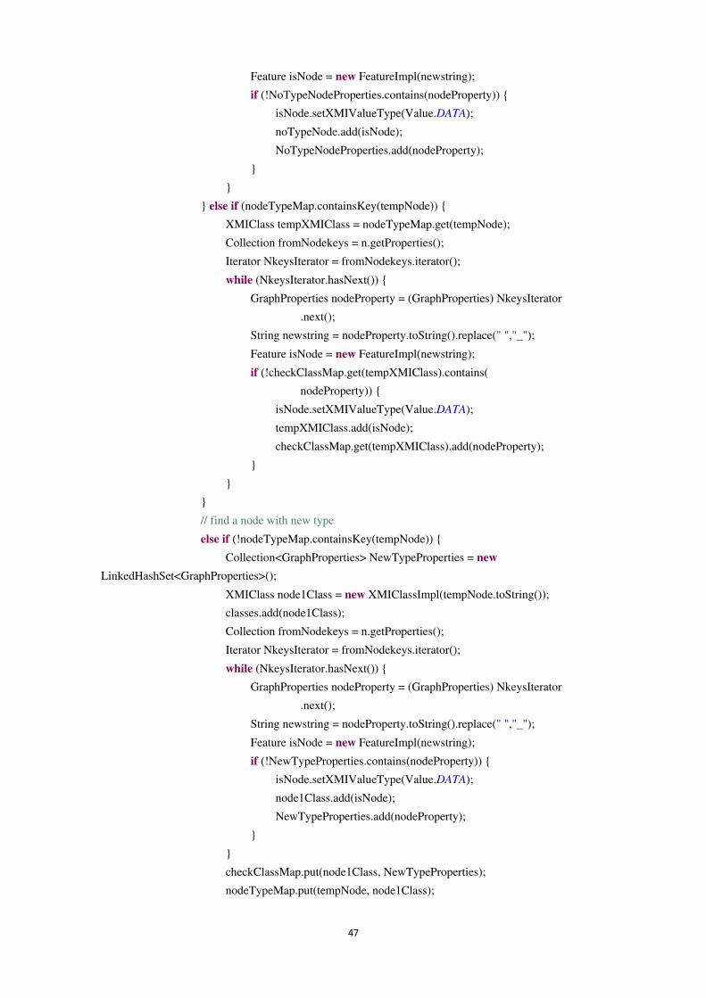
47
Feature isNode = new FeatureImpl(newstring);
if (!NoTypeNodeProperties.contains(nodeProperty)) {
isNode.setXMIValueType(Value.DATA);
noTypeNode.add(isNode);
NoTypeNodeProperties.add(nodeProperty);
}
}
} else if (nodeTypeMap.containsKey(tempNode)) {
XMIClass tempXMIClass = nodeTypeMap.get(tempNode);
Collection fromNodekeys = n.getProperties();
Iterator NkeysIterator = fromNodekeys.iterator();
while (NkeysIterator.hasNext()) {
GraphProperties nodeProperty = (GraphProperties) NkeysIterator
.next();
String newstring = nodeProperty.toString().replace(" ","_");
Feature isNode = new FeatureImpl(newstring);
if (!checkClassMap.get(tempXMIClass).contains(
nodeProperty)) {
isNode.setXMIValueType(Value.DATA);
tempXMIClass.add(isNode);
checkClassMap.get(tempXMIClass).add(nodeProperty);
}
}
}
// find a node with new type
else if (!nodeTypeMap.containsKey(tempNode)) {
Collection<GraphProperties> NewTypeProperties = new
LinkedHashSet<GraphProperties>();
XMIClass node1Class = new XMIClassImpl(tempNode.toString());
classes.add(node1Class);
Collection fromNodekeys = n.getProperties();
Iterator NkeysIterator = fromNodekeys.iterator();
while (NkeysIterator.hasNext()) {
GraphProperties nodeProperty = (GraphProperties) NkeysIterator
.next();
String newstring = nodeProperty.toString().replace(" ","_");
Feature isNode = new FeatureImpl(newstring);
if (!NewTypeProperties.contains(nodeProperty)) {
isNode.setXMIValueType(Value.DATA);
node1Class.add(isNode);
NewTypeProperties.add(nodeProperty);
}
}
checkClassMap.put(node1Class, NewTypeProperties);
nodeTypeMap.put(tempNode, node1Class);
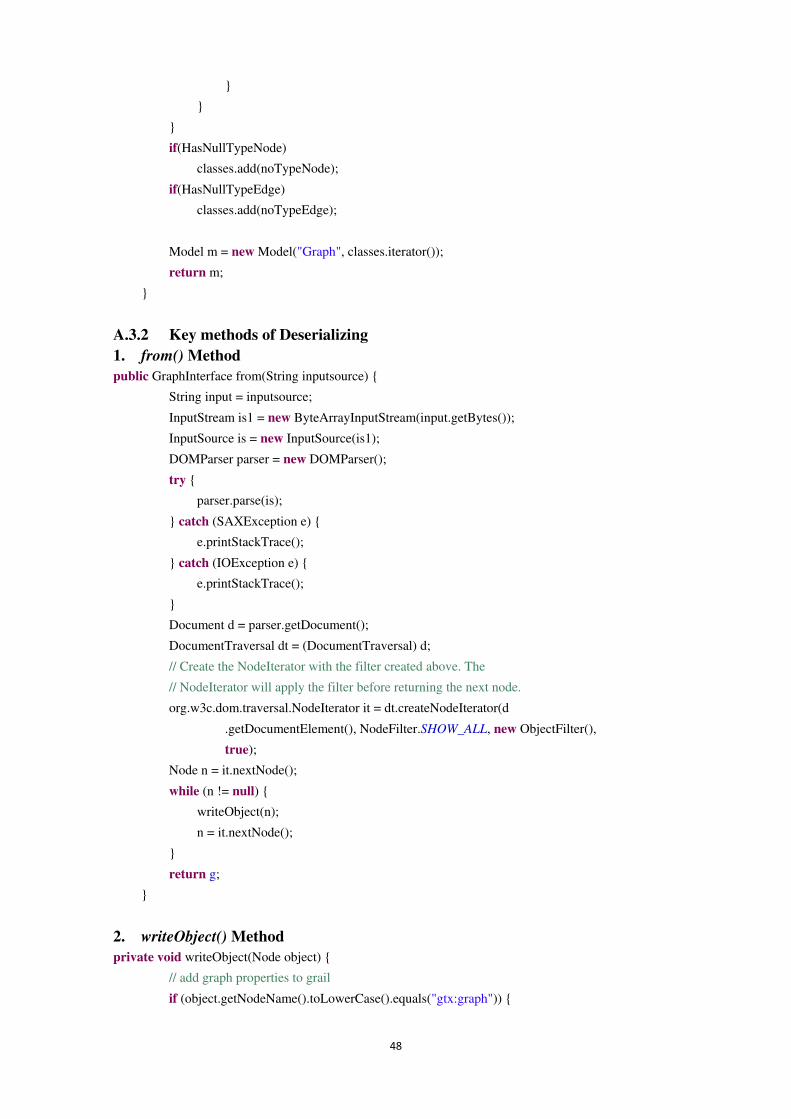
48
}
}
}
if(HasNullTypeNode)
classes.add(noTypeNode);
if(HasNullTypeEdge)
classes.add(noTypeEdge);
Model m = new Model("Graph", classes.iterator());
return m;
}
A.3.2 Key methods of Deserializing 1. from() Method public GraphInterface from(String inputsource) {
String input = inputsource;
InputStream is1 = new ByteArrayInputStream(input.getBytes());
InputSource is = new InputSource(is1);
DOMParser parser = new DOMParser();
try {
parser.parse(is);
} catch (SAXException e) {
e.printStackTrace();
} catch (IOException e) {
e.printStackTrace();
}
Document d = parser.getDocument();
DocumentTraversal dt = (DocumentTraversal) d;
// Create the NodeIterator with the filter created above. The
// NodeIterator will apply the filter before returning the next node.
org.w3c.dom.traversal.NodeIterator it = dt.createNodeIterator(d
.getDocumentElement(), NodeFilter.SHOW_ALL, new ObjectFilter(),
true);
Node n = it.nextNode();
while (n != null) {
writeObject(n);
n = it.nextNode();
}
return g;
}
2. writeObject() Method private void writeObject(Node object) {
// add graph properties to grail
if (object.getNodeName().toLowerCase().equals("gtx:graph")) {
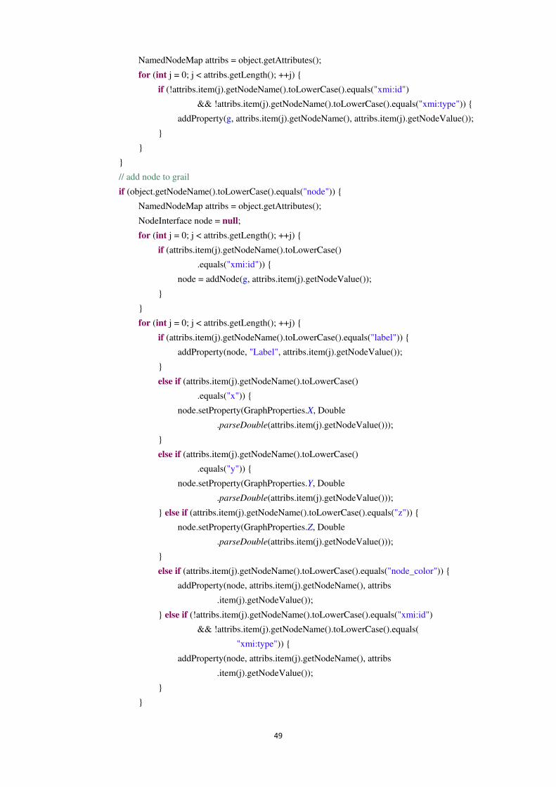
49
NamedNodeMap attribs = object.getAttributes();
for (int j = 0; j < attribs.getLength(); ++j) {
if (!attribs.item(j).getNodeName().toLowerCase().equals("xmi:id")
&& !attribs.item(j).getNodeName().toLowerCase().equals("xmi:type")) {
addProperty(g, attribs.item(j).getNodeName(), attribs.item(j).getNodeValue());
}
}
}
// add node to grail
if (object.getNodeName().toLowerCase().equals("node")) {
NamedNodeMap attribs = object.getAttributes();
NodeInterface node = null;
for (int j = 0; j < attribs.getLength(); ++j) {
if (attribs.item(j).getNodeName().toLowerCase()
.equals("xmi:id")) {
node = addNode(g, attribs.item(j).getNodeValue());
}
}
for (int j = 0; j < attribs.getLength(); ++j) {
if (attribs.item(j).getNodeName().toLowerCase().equals("label")) {
addProperty(node, "Label", attribs.item(j).getNodeValue());
}
else if (attribs.item(j).getNodeName().toLowerCase()
.equals("x")) {
node.setProperty(GraphProperties.X, Double
.parseDouble(attribs.item(j).getNodeValue()));
}
else if (attribs.item(j).getNodeName().toLowerCase()
.equals("y")) {
node.setProperty(GraphProperties.Y, Double
.parseDouble(attribs.item(j).getNodeValue()));
} else if (attribs.item(j).getNodeName().toLowerCase().equals("z")) {
node.setProperty(GraphProperties.Z, Double
.parseDouble(attribs.item(j).getNodeValue()));
}
else if (attribs.item(j).getNodeName().toLowerCase().equals("node_color")) {
addProperty(node, attribs.item(j).getNodeName(), attribs
.item(j).getNodeValue());
} else if (!attribs.item(j).getNodeName().toLowerCase().equals("xmi:id")
&& !attribs.item(j).getNodeName().toLowerCase().equals(
"xmi:type")) {
addProperty(node, attribs.item(j).getNodeName(), attribs
.item(j).getNodeValue());
}
}
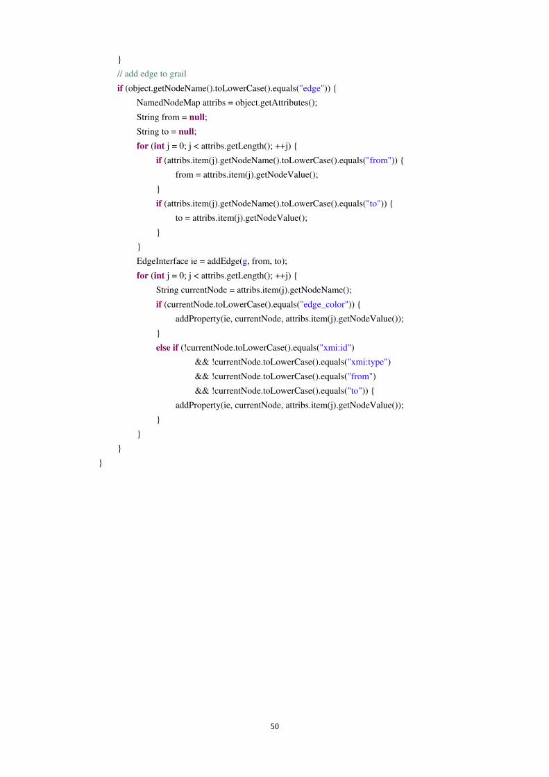
50
}
// add edge to grail
if (object.getNodeName().toLowerCase().equals("edge")) {
NamedNodeMap attribs = object.getAttributes();
String from = null;
String to = null;
for (int j = 0; j < attribs.getLength(); ++j) {
if (attribs.item(j).getNodeName().toLowerCase().equals("from")) {
from = attribs.item(j).getNodeValue();
}
if (attribs.item(j).getNodeName().toLowerCase().equals("to")) {
to = attribs.item(j).getNodeValue();
}
}
EdgeInterface ie = addEdge(g, from, to);
for (int j = 0; j < attribs.getLength(); ++j) {
String currentNode = attribs.item(j).getNodeName();
if (currentNode.toLowerCase().equals("edge_color")) {
addProperty(ie, currentNode, attribs.item(j).getNodeValue());
}
else if (!currentNode.toLowerCase().equals("xmi:id")
&& !currentNode.toLowerCase().equals("xmi:type")
&& !currentNode.toLowerCase().equals("from")
&& !currentNode.toLowerCase().equals("to")) {
addProperty(ie, currentNode, attribs.item(j).getNodeValue());
}
}
}
}

Matematiska och systemtekniska institutionen SE-351 95 Växjö
Tel. +46 (0)470 70 80 00, fax +46 (0)470 840 04
http://www.vxu.se/msi/