Embed Size (px)
Citation preview

Grading: Anything’s Possible Ron Ricks – Parametrix
CV5844-P
You’ve just received a project that includes grading, and you wonder if it’s possible. The project includes access roads with cross slopes onto a complicated site, and it calls for complex drainage swales and detention ponds. You will need to cut into a steep and irregular hillside while maintaining proper drainage, and you’ll have to add integrate and detailed grading to meet project demands. And then, as is the case with most projects, there are changes and additions. Oh, and the end product must be a cohesive 3D model. My objective is to help you turn intimidation and fear (and maybe even some misconceptions) about approaching such complex grading challenges using AutoCAD Civil 3D software into confidence and conviction. We will look at using corridors, feature lines, 3D polylines, and many of the grading tools, and we will examine some techniques to tackle grading and make anything possible.
LearningObjectivesAt the end of this class, you will be able to:
Lose your fears of grading in AutoCAD Civil 3D software
Learn how to use corridors, grading objects, feature lines, 3D polylines, and many of the grading tools for complex grading tasks
Learn how to create complex surfaces from grading
Learn how to modify and add to surfaces
AbouttheSpeaker
Ron Ricks has been in the civil engineering industry for more than 29 years. He spent 24 of those years working extensively with a wide range of Autodesk, Inc., products, becoming very experienced in the company’s Infrastructure software products, including AutoCAD Civil 3D software. He experienced the transition from Land Desktop software to AutoCAD Civil 3D software, gaining vast experience as he applied this technology to civil design and he shifted gears to the new Building Information Modeling (BIM) approach of AutoCAD Civil 3D software. He led and was heavily involved in the development of CADD standards and customized tools for Parametrix, and he was a CADD technician on many projects, several of which involved very complex grading. Ron has been the CAD manager for Parametrix for over 5 years. Located in the Great Northwest, Parametrix is a civil and environmental consulting firm that specializes in transportation, water and wastewater, and environmental projects.
Grading: Anything’s Possible
2
LosingtheFearofGradingWithCivil3D
Thereare3thingstorememberwhendoinggradingwithCivil3D:
HaveconfidenceitcanbedoneThere is a way to accomplish any grading task you run up against. The tools are there. Stay focused on the task at hand and make the technology work for you.
It’sallaboutthesurfaceAlways keep in mind that the surface is what you are working toward. Everything else, such as grading objects, feature lines, and 3D polylines, helps you accomplish your main objective; a stable accurate quality surface. This will help you stay on track and not get bogged down in the tools or technology. This surface can then be used in several valuable ways, such as volume calculations, profiles and sections, and AMG (Automated Machine Guidance).
KeepitsimpleThere is great power in simplicity. Be careful not to over think the grading task at hand. If you look at the overall project it can be intimidating and almost seem impossible. But if you look at one step or one piece of the project at a time, it becomes doable and your confidence builds. As powerful as Civil 3D is, you don’t need to use every command and tool simply because it’s there. For example, there is a purpose for “Sites”, but if your project doesn’t require multiple sites, don’t use them simply because they are in the prospector. Another example is “Grading Groups”, which they have their purpose, but many times they are not necessary – one grading group for an entire project could be enough. Keep the data simple. Don’t keep a lot of alternative or old surfaces, alignments, corridors, or other Civil 3D data because you don’t dare get rid of them. Once they have served their purpose, delete them from prospector. This will make your file more efficient and you will have less crashes. Some steps you can take to simplify your file are:
Once in a while audit all of your Civil 3D data in prospector and remove data you no longer need, such as volume surfaces, sections, and other data that no longer serve a purpose. If you’re nervous, backup the file first on a CD for future reference.
Keep the existing surface, or any other surface that’s not part of the grading you are working on, in a separate file and data shortcut it into the design file you are working in.
Crop existing surfaces to the size you need. Do this by selecting the surface then in the ribbon pick the “Surface Tools” drop down and pick create cropped surface.
Don’t save things on frozen layers. If you feel you need to keep that data, make a copy of the file for future reference. Then delete those layers form your file.
Purge layers, blocks, and anything else you don’t need. This is good to check once in a while.
Avoid a lot of data shortcuts of data you aren’t using. If you don’t watch this, it can get out of hand, especially on large projects.
Grading: Anything’s Possible
3
Weed out vertices of 3D polylines and Feature Lines that are used to create surfaces. Do this before you create the surface. This can make a huge difference in the size and performance of the file.
You may consider creating a “Snapshot” of a surface. By doing this you are able to delete the objects in the file that were used to create the surface, reducing the file size. Just be careful not to ever remove the snapshot until the surface is no longer needed.
Let’sTakeaLook
MethodsandTools
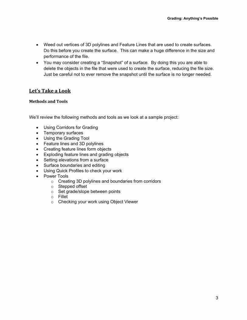
We’ll review the following methods and tools as we look at a sample project:
Using Corridors for Grading Temporary surfaces Using the Grading Tool Feature lines and 3D polylines Creating feature lines form objects Exploding feature lines and grading objects Setting elevations from a surface Surface boundaries and editing Using Quick Profiles to check your work Power Tools
o Creating 3D polylines and boundaries from corridors o Stepped offset o Set grade/slope between points o Fillet o Checking your work using Object Viewer
Grading: Anything’s Possible
4
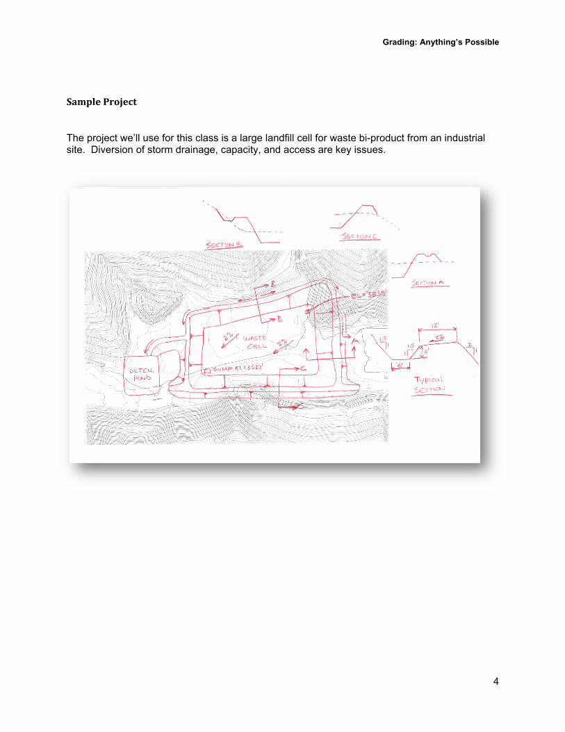
SampleProject
The project we’ll use for this class is a large landfill cell for waste bi-product from an industrial site. Diversion of storm drainage, capacity, and access are key issues.
Grading: Anything’s Possible
5
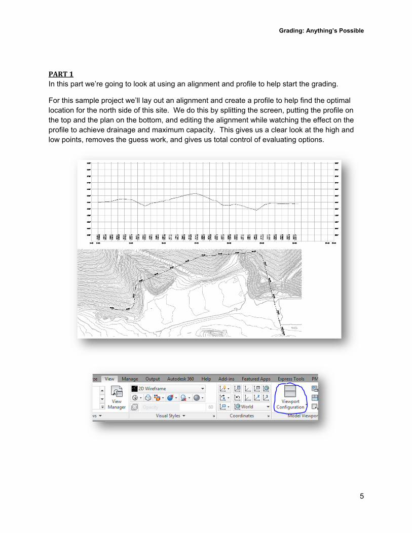
PART1In this part we’re going to look at using an alignment and profile to help start the grading.
For this sample project we’ll lay out an alignment and create a profile to help find the optimal location for the north side of this site. We do this by splitting the screen, putting the profile on the top and the plan on the bottom, and editing the alignment while watching the effect on the profile to achieve drainage and maximum capacity. This gives us a clear look at the high and low points, removes the guess work, and gives us total control of evaluating options.
Grading: Anything’s Possible
6
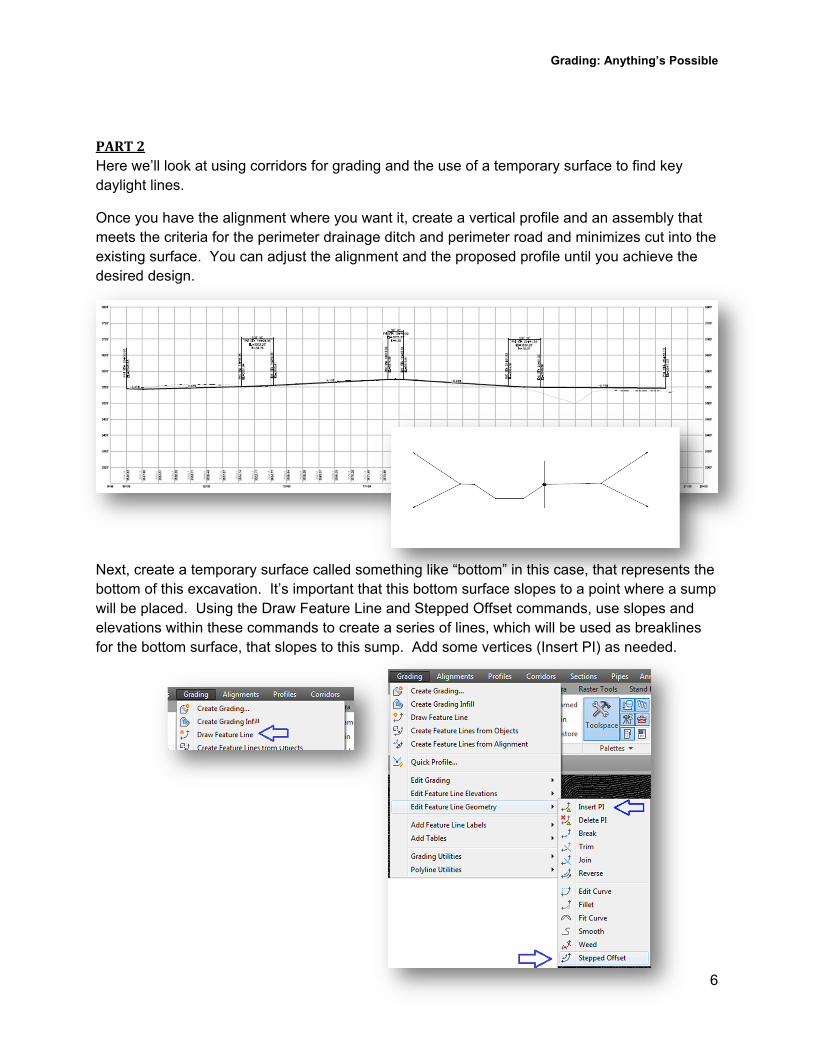
PART2Here we’ll look at using corridors for grading and the use of a temporary surface to find key daylight lines.
Once you have the alignment where you want it, create a vertical profile and an assembly that meets the criteria for the perimeter drainage ditch and perimeter road and minimizes cut into the existing surface. You can adjust the alignment and the proposed profile until you achieve the desired design.
Next, create a temporary surface called something like “bottom” in this case, that represents the bottom of this excavation. It’s important that this bottom surface slopes to a point where a sump will be placed. Using the Draw Feature Line and Stepped Offset commands, use slopes and elevations within these commands to create a series of lines, which will be used as breaklines for the bottom surface, that slopes to this sump. Add some vertices (Insert PI) as needed.
Grading: Anything’s Possible
7
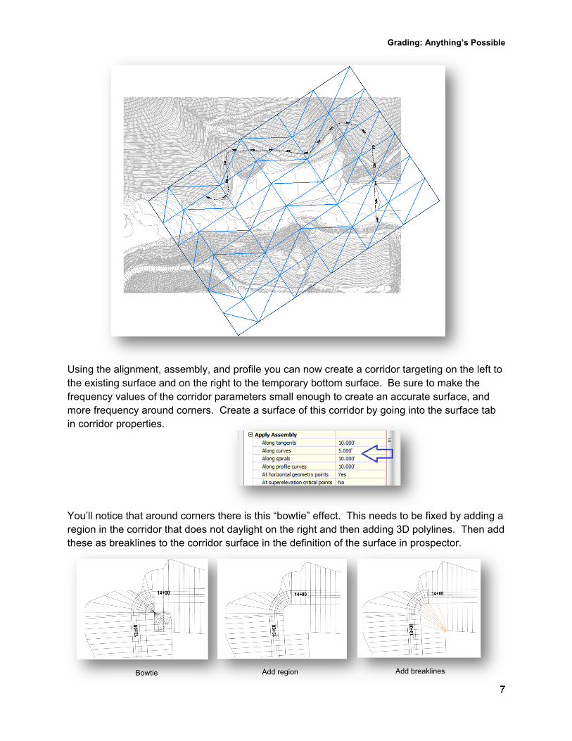
Bowtie Add region Add breaklines
Using the alignment, assembly, and profile you can now create a corridor targeting on the left to the existing surface and on the right to the temporary bottom surface. Be sure to make the frequency values of the corridor parameters small enough to create an accurate surface, and more frequency around corners. Create a surface of this corridor by going into the surface tab in corridor properties.
You’ll notice that around corners there is this “bowtie” effect. This needs to be fixed by adding a region in the corridor that does not daylight on the right and then adding 3D polylines. Then add these as breaklines to the corridor surface in the definition of the surface in prospector.
Grading: Anything’s Possible
8
Initial alignment
After alignment PI adjustment
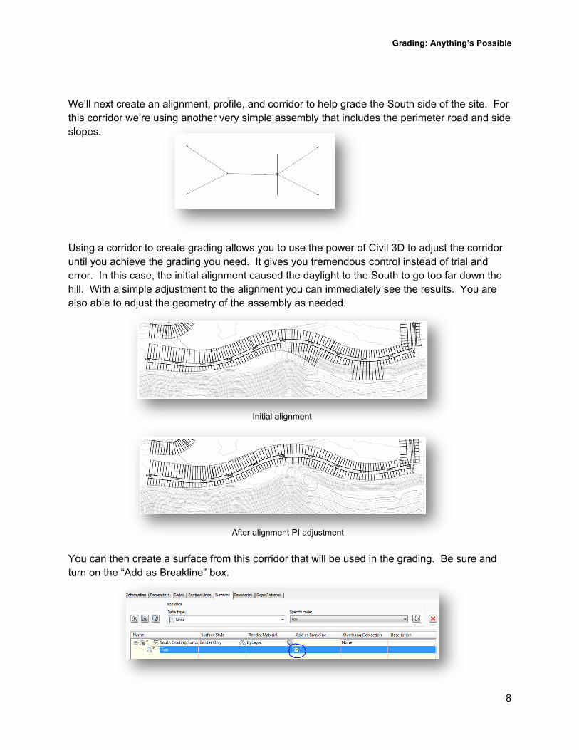
We’ll next create an alignment, profile, and corridor to help grade the South side of the site. For this corridor we’re using another very simple assembly that includes the perimeter road and side slopes.
Using a corridor to create grading allows you to use the power of Civil 3D to adjust the corridor until you achieve the grading you need. It gives you tremendous control instead of trial and error. In this case, the initial alignment caused the daylight to the South to go too far down the hill. With a simple adjustment to the alignment you can immediately see the results. You are also able to adjust the geometry of the assembly as needed.
You can then create a surface from this corridor that will be used in the grading. Be sure and turn on the “Add as Breakline” box.
Grading: Anything’s Possible
9
PART3Next we’re going to look at extracting 3D polylines from the corridor for further grading and start pasting surfaces together.
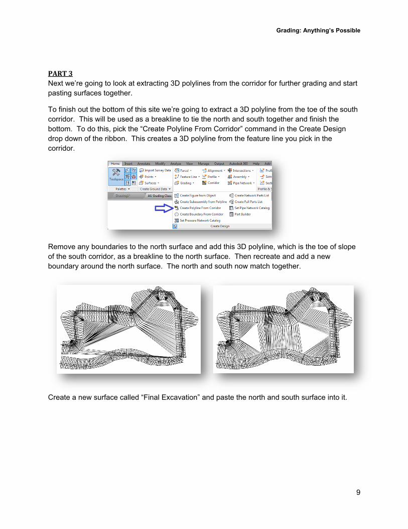
To finish out the bottom of this site we’re going to extract a 3D polyline from the toe of the south corridor. This will be used as a breakline to tie the north and south together and finish the bottom. To do this, pick the “Create Polyline From Corridor” command in the Create Design drop down of the ribbon. This creates a 3D polyline from the feature line you pick in the corridor.
Remove any boundaries to the north surface and add this 3D polyline, which is the toe of slope of the south corridor, as a breakline to the north surface. Then recreate and add a new boundary around the north surface. The north and south now match together.
Create a new surface called “Final Excavation” and paste the north and south surface into it.
Grading: Anything’s Possible
10
Trim and Join 3D polylines Fillet corners
PART4This part will highlight some powerful grading tools that are indispensable when doing complex grading as we grade in a berm and detention pond.
Many of these commands work with 3D polylines, not just feature lines. Only these shown will be highlighted in this class. However, the commands we don’t highlight are very useful and serve an important purpose in grading in different situations.
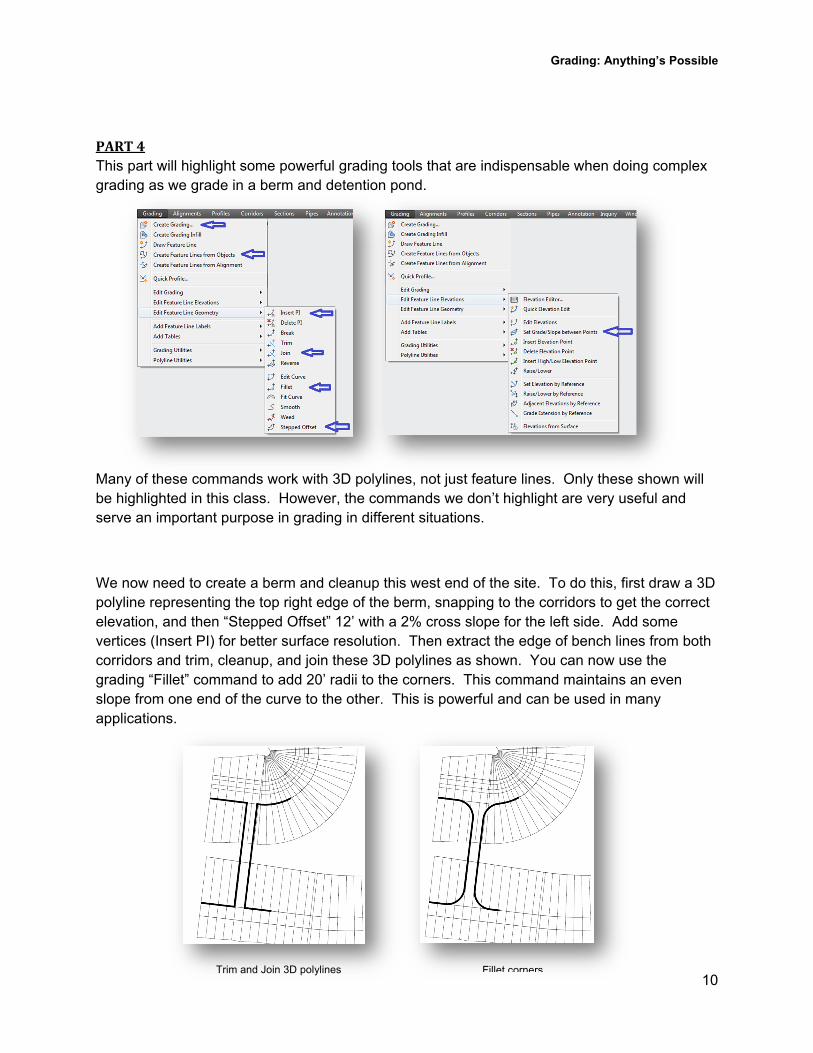
We now need to create a berm and cleanup this west end of the site. To do this, first draw a 3D polyline representing the top right edge of the berm, snapping to the corridors to get the correct elevation, and then “Stepped Offset” 12’ with a 2% cross slope for the left side. Add some vertices (Insert PI) for better surface resolution. Then extract the edge of bench lines from both corridors and trim, cleanup, and join these 3D polylines as shown. You can now use the grading “Fillet” command to add 20’ radii to the corners. This command maintains an even slope from one end of the curve to the other. This is powerful and can be used in many applications.
Grading: Anything’s Possible
11
3D polylines added Object Viewer
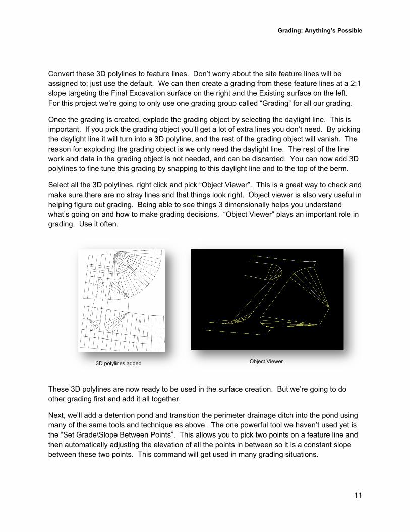
Convert these 3D polylines to feature lines. Don’t worry about the site feature lines will be assigned to; just use the default. We can then create a grading from these feature lines at a 2:1 slope targeting the Final Excavation surface on the right and the Existing surface on the left. For this project we’re going to only use one grading group called “Grading” for all our grading.
Once the grading is created, explode the grading object by selecting the daylight line. This is important. If you pick the grading object you’ll get a lot of extra lines you don’t need. By picking the daylight line it will turn into a 3D polyline, and the rest of the grading object will vanish. The reason for exploding the grading object is we only need the daylight line. The rest of the line work and data in the grading object is not needed, and can be discarded. You can now add 3D polylines to fine tune this grading by snapping to this daylight line and to the top of the berm.
Select all the 3D polylines, right click and pick “Object Viewer”. This is a great way to check and make sure there are no stray lines and that things look right. Object viewer is also very useful in helping figure out grading. Being able to see things 3 dimensionally helps you understand what’s going on and how to make grading decisions. “Object Viewer” plays an important role in grading. Use it often.
These 3D polylines are now ready to be used in the surface creation. But we’re going to do other grading first and add it all together.
Next, we’ll add a detention pond and transition the perimeter drainage ditch into the pond using many of the same tools and technique as above. The one powerful tool we haven’t used yet is the “Set Grade\Slope Between Points”. This allows you to pick two points on a feature line and then automatically adjusting the elevation of all the points in between so it is a constant slope between these two points. This command will get used in many grading situations.
Grading: Anything’s Possible
12
*Note: If the bottom of the pond needs to slope to a point, such as a sump in one corner, you could create a temporary surface to grade to that accomplishes this slope.
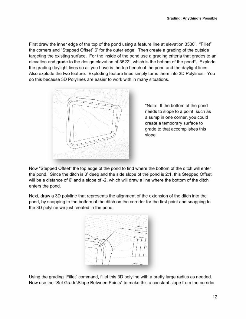
First draw the inner edge of the top of the pond using a feature line at elevation 3530’. “Fillet” the corners and “Stepped Offset” 6’ for the outer edge. Then create a grading of the outside targeting the existing surface. For the inside of the pond use a grading criteria that grades to an elevation and grade to the design elevation of 3522’, which is the bottom of the pond*. Explode the grading daylight lines so all you have is the top bench of the pond and the daylight lines. Also explode the two feature. Exploding feature lines simply turns them into 3D Polylines. You do this because 3D Polylines are easier to work with in many situations.
Now “Stepped Offset” the top edge of the pond to find where the bottom of the ditch will enter the pond. Since the ditch is 3’ deep and the side slope of the pond is 2:1, this Stepped Offset will be a distance of 6’ and a slope of -2, which will draw a line where the bottom of the ditch enters the pond.
Next, draw a 3D polyline that represents the alignment of the extension of the ditch into the pond, by snapping to the bottom of the ditch on the corridor for the first point and snapping to the 3D polyline we just created in the pond.
Using the grading “Fillet” command, fillet this 3D polyline with a pretty large radius as needed. Now use the “Set Grade\Slope Between Points” to make this a constant slope from the corridor
Grading: Anything’s Possible
13
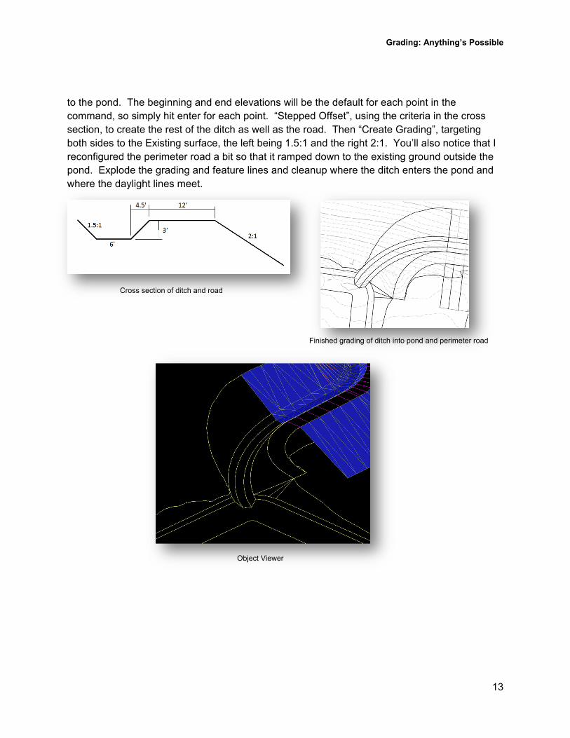
Cross section of ditch and road
Finished grading of ditch into pond and perimeter road
Object Viewer
to the pond. The beginning and end elevations will be the default for each point in the command, so simply hit enter for each point. “Stepped Offset”, using the criteria in the cross section, to create the rest of the ditch as well as the road. Then “Create Grading”, targeting both sides to the Existing surface, the left being 1.5:1 and the right 2:1. You’ll also notice that I reconfigured the perimeter road a bit so that it ramped down to the existing ground outside the pond. Explode the grading and feature lines and cleanup where the ditch enters the pond and where the daylight lines meet.
Grading: Anything’s Possible
14
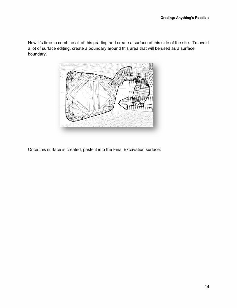
Now it’s time to combine all of this grading and create a surface of this side of the site. To avoid a lot of surface editing, create a boundary around this area that will be used as a surface boundary.
Once this surface is created, paste it into the Final Excavation surface.
Grading: Anything’s Possible
15
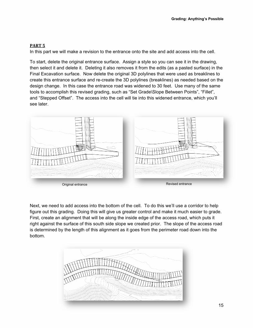
Original entrance Revised entrance
PART5In this part we will make a revision to the entrance onto the site and add access into the cell.
To start, delete the original entrance surface. Assign a style so you can see it in the drawing, then select it and delete it. Deleting it also removes it from the edits (as a pasted surface) in the Final Excavation surface. Now delete the original 3D polylines that were used as breaklines to create this entrance surface and re-create the 3D polylines (breaklines) as needed based on the design change. In this case the entrance road was widened to 30 feet. Use many of the same tools to accomplish this revised grading, such as “Set Grade\Slope Between Points”, “Fillet”, and “Stepped Offset”. The access into the cell will tie into this widened entrance, which you’ll see later.
Next, we need to add access into the bottom of the cell. To do this we’ll use a corridor to help figure out this grading. Doing this will give us greater control and make it much easier to grade. First, create an alignment that will be along the inside edge of the access road, which puts it right against the surface of this south side slope we created prior. The slope of the access road is determined by the length of this alignment as it goes from the perimeter road down into the bottom.
Grading: Anything’s Possible
16
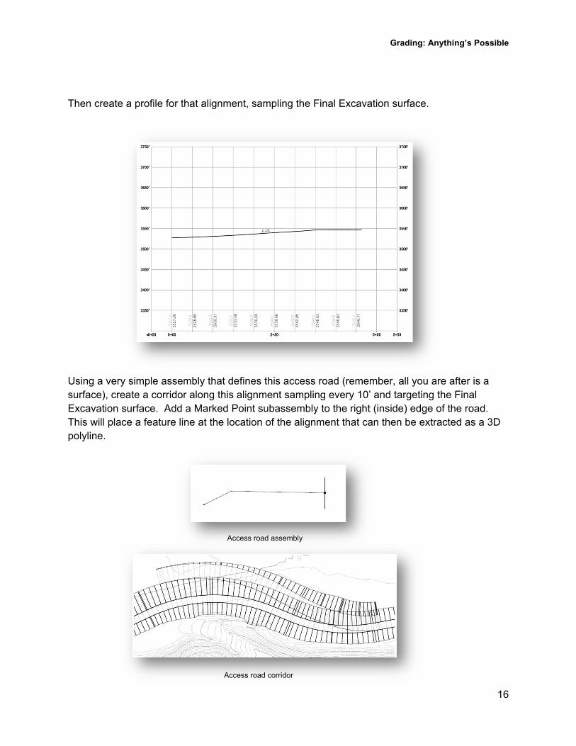
Access road assembly
Access road corridor
Then create a profile for that alignment, sampling the Final Excavation surface.
Using a very simple assembly that defines this access road (remember, all you are after is a surface), create a corridor along this alignment sampling every 10’ and targeting the Final Excavation surface. Add a Marked Point subassembly to the right (inside) edge of the road. This will place a feature line at the location of the alignment that can then be extracted as a 3D polyline.
Grading: Anything’s Possible
17
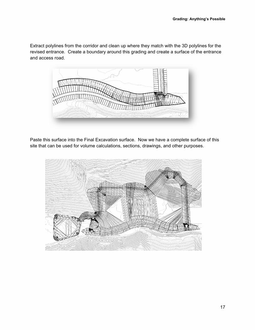
Extract polylines from the corridor and clean up where they match with the 3D polylines for the revised entrance. Create a boundary around this grading and create a surface of the entrance and access road.
Paste this surface into the Final Excavation surface. Now we have a complete surface of this site that can be used for volume calculations, sections, drawings, and other purposes.
Grading: Anything’s Possible
18
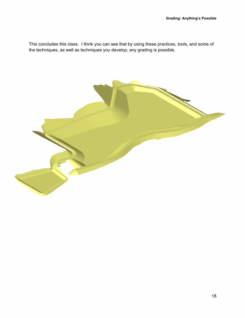
This concludes this class. I think you can see that by using these practices, tools, and some of the techniques, as well as techniques you develop, any grading is possible.