Embed Size (px)
Citation preview
Vision, Modeling, and Visualization (2012)M. Goesele, T. Grosch, B. Preim, H. Theisel, and K. Toennies (Eds.)
GPU-accelerated Interactive Material Aging
Tobias Günther Kai Rohmer Thorsten Grosch
Computational Visualistics group, University of Magdeburg, Germany
Abstract
A photorealistic appearance of a 3D scene is required in many applications today. Thereby, one vital aspect is theusage of realistic materials, for which a broad variety of reflectance models is available. When directly employingthose models, surfaces always look new, which contrasts strongly the real objects surrounding us as they haveundergone diverse kinds of aging processes. The literature already proposes a set of viable methods to simulatedifferent aging phenomena, but all of them are computationally expensive and can thus only be computed off-line.Therefore, this paper presents the first interactive, GPU-accelerated method to simulate material aging in a givenscene. Thereby, our approach allows artists to precisely control the course of the aging process. Our particle-based method is capable to reproduce the most common deterioration phenomena in a few seconds, includingplausible dirt bleeding, flow effects, corrosion and patina.
This is the authors preprint.The definitive version of the paper is available at http://diglib.eg.org/EG/DL/PE/VMV/VMV12/063-070.pdf.
1. Introduction
The faithful reproduction of realistic appearances is one ofthe ultimate goals computer graphics researchers have beenpursuing for decades. Thereby, a key aspect is the resem-blance to natural phenomena, among those the weatheringand aging of materials over time. Content artists spend muchtime meticulously facilitating the appearance of 3D objectsby editing their textures, whereby each inaccuracy can causeimplausibility and quickly break the immersion. For exam-ple, a repositioned object undergoes different processes if itsweathering side changed or is suddenly blocked, which canalso render the content artist’s work void if a scene designerdecides to rearrange the objects. Not only to favor plausi-bility of effects caused by interacting objects and to lowerproduction costs, fast simulations of weathering phenomenaare vitally needed. Furthermore, robust simulations can con-tribute to ever-changing environments, thereby taking virtualreality to a new experience. Several methods exist to modelthe simulation of the chemical, biological and mechanicalprocesses involved here, but run in the order of minutes orhours, thus are far from reaching interactive frame rates, yet.
In this paper, we demonstrate the – to the best of ourknowledge – first simulation of aging processes at interac-tive frame rates, by harnessing the processing power of mod-
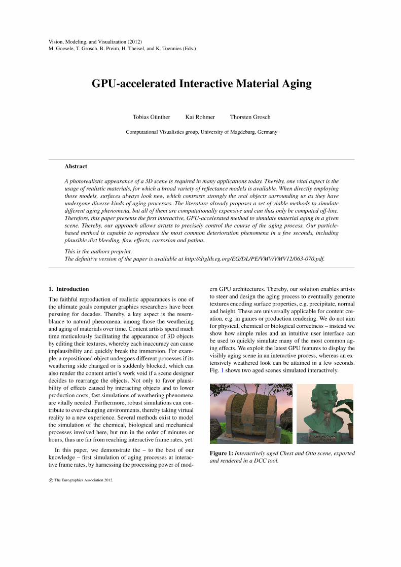
ern GPU architectures. Thereby, our solution enables artiststo steer and design the aging process to eventually generatetextures encoding surface properties, e.g. precipitate, normaland height. These are universally applicable for content cre-ation, e.g. in games or production rendering. We do not aimfor physical, chemical or biological correctness – instead weshow how simple rules and an intuitive user interface canbe used to quickly simulate many of the most common ag-ing effects. We exploit the latest GPU features to display thevisibly aging scene in an interactive process, whereas an ex-tensively weathered look can be attained in a few seconds.Fig. 1 shows two aged scenes simulated interactively.
Figure 1: Interactively aged Chest and Otto scene, exportedand rendered in a DCC tool.
c© The Eurographics Association 2012.
Tobias Günther, Kai Rohmer & Thorsten Grosch / GPU-accelerated Interactive Material Aging
2. Previous Work
Material aging processes can be categorized into chemi-cal, mechanical, and biological processes [MG08]. Chemicalprocesses include the temporal change of metal, e.g. corro-sion introducing rust [MDG01], or the formation of a patinalayer on copper [DH96]. Mechanical processes alter theshape of the object, including the deformation due to cracks[HTK98, HTK00, GC01], peeling [WNH97, PPD02], andman-made influences like scratches [BPMG04] and impacts[PPD01] on the surface. Examples of biological processesare organic lichen growth [DGA04], mould and decay aswell as wrinkles in fruits [KRB11]. Many aging processes,like erosion and weathered stone [DEJ∗99], can be charac-terized as a combination of multiple processes [MG08]. As asimulation type, statistical methods can be used [WTL∗06],as well as captured photographs over time [GTR∗06], or par-ticle simulations. Particles are especially expedient to de-scribe the flow of dirt along the surface [DPH96]. A moregeneral particle-based approach was presented by Chen etal. [CXW∗05], allowing the simulation of a wider rangeof aging phenomena, including dirt bleeding and erosion.Tools like BRDF-Shop [CPK06] can be used to design user-defined materials. In addition, 3D-painting [HH90] allows adirect manipulation of the color on the 3D-surface. However,a direct design of the aging process is not yet possible.
3. Overview
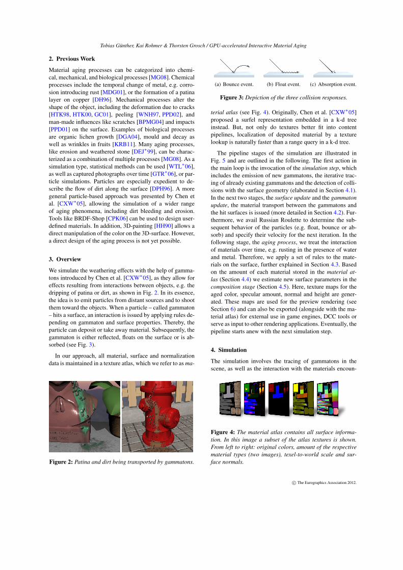
We simulate the weathering effects with the help of gamma-tons introduced by Chen et al. [CXW∗05], as they allow foreffects resulting from interactions between objects, e.g. thedripping of patina or dirt, as shown in Fig. 2. In its essence,the idea is to emit particles from distant sources and to shootthem toward the objects. When a particle – called gammaton– hits a surface, an interaction is issued by applying rules de-pending on gammaton and surface properties. Thereby, theparticle can deposit or take away material. Subsequently, thegammaton is either reflected, floats on the surface or is ab-sorbed (see Fig. 3).
In our approach, all material, surface and normalizationdata is maintained in a texture atlas, which we refer to as ma-
Figure 2: Patina and dirt being transported by gammatons.
(a) Bounce event. (b) Float event. (c) Absorption event.
Figure 3: Depiction of the three collision responses.
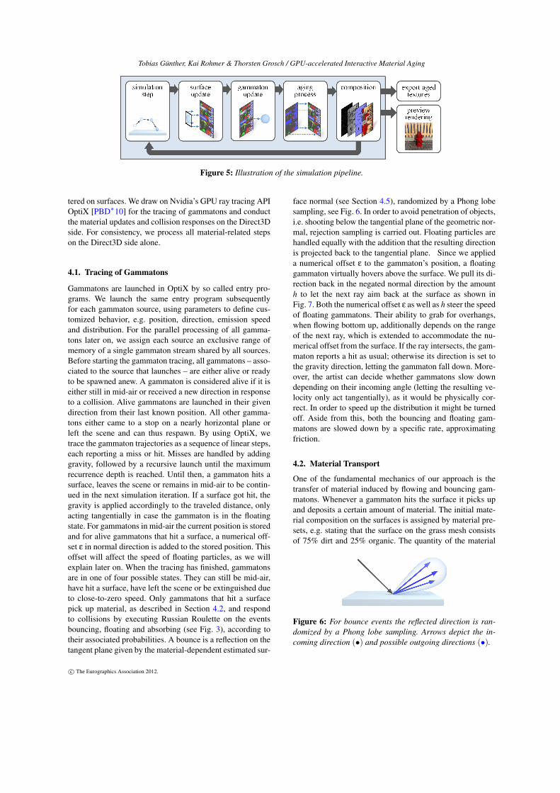
terial atlas (see Fig. 4). Originally, Chen et al. [CXW∗05]proposed a surfel representation embedded in a k-d treeinstead. But, not only do textures better fit into contentpipelines, localization of deposited material by a texturelookup is naturally faster than a range query in a k-d tree.
The pipeline stages of the simulation are illustrated inFig. 5 and are outlined in the following. The first action inthe main loop is the invocation of the simulation step, whichincludes the emission of new gammatons, the iterative trac-ing of already existing gammatons and the detection of colli-sions with the surface geometry (elaborated in Section 4.1).In the next two stages, the surface update and the gammatonupdate, the material transport between the gammatons andthe hit surfaces is issued (more detailed in Section 4.2). Fur-thermore, we avail Russian Roulette to determine the sub-sequent behavior of the particles (e.g. float, bounce or ab-sorb) and specify their velocity for the next iteration. In thefollowing stage, the aging process, we treat the interactionof materials over time, e.g. rusting in the presence of waterand metal. Therefore, we apply a set of rules to the mate-rials on the surface, further explained in Section 4.3. Basedon the amount of each material stored in the material at-las (Section 4.4) we estimate new surface parameters in thecomposition stage (Section 4.5). Here, texture maps for theaged color, specular amount, normal and height are gener-ated. These maps are used for the preview rendering (seeSection 6) and can also be exported (alongside with the ma-terial atlas) for external use in game engines, DCC tools orserve as input to other rendering applications. Eventually, thepipeline starts anew with the next simulation step.
4. Simulation
The simulation involves the tracing of gammatons in thescene, as well as the interaction with the materials encoun-
Figure 4: The material atlas contains all surface informa-tion. In this image a subset of the atlas textures is shown.From left to right: original colors, amount of the respectivematerial types (two images), texel-to-world scale and sur-face normals.
c© The Eurographics Association 2012.
Tobias Günther, Kai Rohmer & Thorsten Grosch / GPU-accelerated Interactive Material Aging
Figure 5: Illustration of the simulation pipeline.
tered on surfaces. We draw on Nvidia’s GPU ray tracing APIOptiX [PBD∗10] for the tracing of gammatons and conductthe material updates and collision responses on the Direct3Dside. For consistency, we process all material-related stepson the Direct3D side alone.
4.1. Tracing of Gammatons
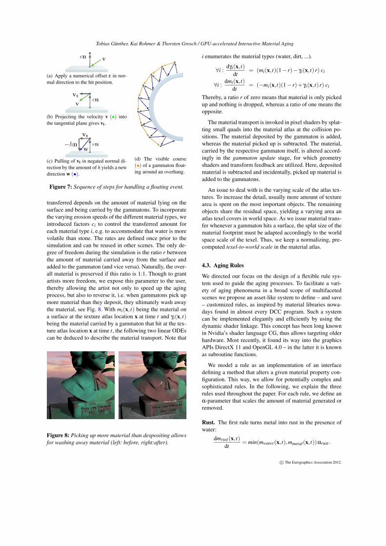
Gammatons are launched in OptiX by so called entry pro-grams. We launch the same entry program subsequentlyfor each gammaton source, using parameters to define cus-tomized behavior, e.g. position, direction, emission speedand distribution. For the parallel processing of all gamma-tons later on, we assign each source an exclusive range ofmemory of a single gammaton stream shared by all sources.Before starting the gammaton tracing, all gammatons – asso-ciated to the source that launches – are either alive or readyto be spawned anew. A gammaton is considered alive if it iseither still in mid-air or received a new direction in responseto a collision. Alive gammatons are launched in their givendirection from their last known position. All other gamma-tons either came to a stop on a nearly horizontal plane orleft the scene and can thus respawn. By using OptiX, wetrace the gammaton trajectories as a sequence of linear steps,each reporting a miss or hit. Misses are handled by addinggravity, followed by a recursive launch until the maximumrecurrence depth is reached. Until then, a gammaton hits asurface, leaves the scene or remains in mid-air to be contin-ued in the next simulation iteration. If a surface got hit, thegravity is applied accordingly to the traveled distance, onlyacting tangentially in case the gammaton is in the floatingstate. For gammatons in mid-air the current position is storedand for alive gammatons that hit a surface, a numerical off-set ε in normal direction is added to the stored position. Thisoffset will affect the speed of floating particles, as we willexplain later on. When the tracing has finished, gammatonsare in one of four possible states. They can still be mid-air,have hit a surface, have left the scene or be extinguished dueto close-to-zero speed. Only gammatons that hit a surfacepick up material, as described in Section 4.2, and respondto collisions by executing Russian Roulette on the eventsbouncing, floating and absorbing (see Fig. 3), according totheir associated probabilities. A bounce is a reflection on thetangent plane given by the material-dependent estimated sur-
face normal (see Section 4.5), randomized by a Phong lobesampling, see Fig. 6. In order to avoid penetration of objects,i.e. shooting below the tangential plane of the geometric nor-mal, rejection sampling is carried out. Floating particles arehandled equally with the addition that the resulting directionis projected back to the tangential plane. Since we applieda numerical offset ε to the gammaton’s position, a floatinggammaton virtually hovers above the surface. We pull its di-rection back in the negated normal direction by the amounth to let the next ray aim back at the surface as shown inFig. 7. Both the numerical offset ε as well as h steer the speedof floating gammatons. Their ability to grab for overhangs,when flowing bottom up, additionally depends on the rangeof the next ray, which is extended to accommodate the nu-merical offset from the surface. If the ray intersects, the gam-maton reports a hit as usual; otherwise its direction is set tothe gravity direction, letting the gammaton fall down. More-over, the artist can decide whether gammatons slow downdepending on their incoming angle (letting the resulting ve-locity only act tangentially), as it would be physically cor-rect. In order to speed up the distribution it might be turnedoff. Aside from this, both the bouncing and floating gam-matons are slowed down by a specific rate, approximatingfriction.
4.2. Material Transport
One of the fundamental mechanics of our approach is thetransfer of material induced by flowing and bouncing gam-matons. Whenever a gammaton hits the surface it picks upand deposits a certain amount of material. The initial mate-rial composition on the surfaces is assigned by material pre-sets, e.g. stating that the surface on the grass mesh consistsof 75% dirt and 25% organic. The quantity of the material
Figure 6: For bounce events the reflected direction is ran-domized by a Phong lobe sampling. Arrows depict the in-coming direction (•) and possible outgoing directions (•).
c© The Eurographics Association 2012.
Tobias Günther, Kai Rohmer & Thorsten Grosch / GPU-accelerated Interactive Material Aging
vεn
(a) Apply a numerical offset ε in nor-mal direction to the hit position.
v
vtεn
(b) Projecting the velocity v (•) intothe tangential plane gives vt.
−hn εn
vt
w
(c) Pulling of vt in negated normal di-rection by the amount of h yields a newdirection w (•).
(d) The visible course(•) of a gammaton float-ing around an overhang.
Figure 7: Sequence of steps for handling a floating event.
transferred depends on the amount of material lying on thesurface and being carried by the gammatons. To incorporatethe varying erosion speeds of the different material types, weintroduced factors ci to control the transferred amount foreach material type i, e.g. to accommodate that water is morevolatile than stone. The rates are defined once prior to thesimulation and can be reused in other scenes. The only de-gree of freedom during the simulation is the ratio r betweenthe amount of material carried away from the surface andadded to the gammaton (and vice versa). Naturally, the over-all material is preserved if this ratio is 1:1. Though to grantartists more freedom, we expose this parameter to the user,thereby allowing the artist not only to speed up the agingprocess, but also to reverse it, i.e. when gammatons pick upmore material than they deposit, they ultimately wash awaythe material, see Fig. 8. With mi(x, t) being the material ona surface at the texture atlas location x at time t and γi(x, t)being the material carried by a gammaton that hit at the tex-ture atlas location x at time t, the following two linear ODEscan be deduced to describe the material transport. Note that
Figure 8: Picking up more material than despositing allowsfor washing away material (left: before, right:after).
i enumerates the material types (water, dirt, ...).
∀i :dγi(x, t)
dt= (mi(x, t)(1− r)− γi(x, t)r) ci
∀i :dmi(x, t)
dt= (−mi(x, t)(1− r)+ γi(x, t)r) ci
Thereby, a ratio r of zero means that material is only pickedup and nothing is dropped, whereas a ratio of one means theopposite.
The material transport is invoked in pixel shaders by splat-ting small quads into the material atlas at the collision po-sitions. The material deposited by the gammaton is added,whereas the material picked up is subtracted. The material,carried by the respective gammaton itself, is altered accord-ingly in the gammaton update stage, for which geometryshaders and transform feedback are utilized. Here, depositedmaterial is subtracted and incidentally, picked up material isadded to the gammatons.
An issue to deal with is the varying scale of the atlas tex-tures. To increase the detail, usually more amount of texturearea is spent on the most important objects. The remainingobjects share the residual space, yielding a varying area anatlas texel covers in world space. As we issue material trans-fer whenever a gammaton hits a surface, the splat size of thematerial footprint must be adapted accordingly to the worldspace scale of the texel. Thus, we keep a normalizing, pre-computed texel-to-world scale in the material atlas.
4.3. Aging Rules
We directed our focus on the design of a flexible rule sys-tem used to guide the aging processes. To facilitate a vari-ety of aging phenomena in a broad scope of multifacetedscenes we propose an asset-like system to define – and save– customized rules, as inspired by material libraries nowa-days found in almost every DCC program. Such a systemcan be implemented elegantly and efficiently by using thedynamic shader linkage. This concept has been long knownin Nvidia’s shader language CG, thus allows targeting olderhardware. Most recently, it found its way into the graphicsAPIs DirectX 11 and OpenGL 4.0 – in the latter it is knownas subroutine functions.
We model a rule as an implementation of an interfacedefining a method that alters a given material property con-figuration. This way, we allow for potentially complex andsophisticated rules. In the following, we explain the threerules used throughout the paper. For each rule, we define anα-parameter that scales the amount of material generated orremoved.
Rust. The first rule turns metal into rust in the presence ofwater:
dmrust(x, t)dt
= min(mwater(x, t),mmetal(x, t))αrust .
c© The Eurographics Association 2012.
Tobias Günther, Kai Rohmer & Thorsten Grosch / GPU-accelerated Interactive Material Aging
Decay. The second rule is used to weather wood by produc-ing organic material and dirt:
dmorganic(x, t)dt
= min(mwater(x, t),mwood(x, t))αorganic
dmdirt(x, t)dt
= min(mwater(x, t),mwood(x, t))αdirt .
Evaporation. The last rule evaporates water over time:
dmwater(x, t)dt
=−αwater.
4.4. Data Formats
In the following section, we take a closer look on thedata structures involved in the implementation. Of partic-ular interest are the formats used to store the materialson the surface and at the gammatons. For the informationon the surfaces we use the material atlas, thus beforehanda parameterization is required, which we obtained semi-automatically using standard DCC tools. The material at-las contains colors + specular coefficient (RGBA8), facenormals (RGB16F), face tangents (RGB16F), shading nor-mals (RGB16F), materials (ping-pong of 2× RGBA8), orig-inal materials (2× RGBA8) and a texture-to-world scale(RG16F). The memory consumption is a non-negligible is-sue, especially due to the high bandwidth workload, thuswe reduced the materials to 256 discrete steps each, using8 materials in total. To attain more granularity on the lowlydiscretized materials, we invoke the aging rules with a cus-tomizable probability. As opposed to our probabilistic ap-proach, it suggests itself to invoke a rule every n frames,which however is not viable as it may yield discernible, pe-riodic popping artifacts in the rendered image.
The 8 material slots can be assigned to certain materials,as they are required in the particular scene. Throughout thepaper we needed 7 slots for water, dirt, metal, wood, organic,rust and stone. Output of the simulation are the composedtextures, containing the aged color (RGB8), normal (RGB8)height (R8) and specularity (R8). Each gammaton stores itsposition (float3), the velocity (float3), the carried material(uint2), the texture coordinates (float2) of the surface it lasthit, its state (uint) – as explained in Section 4.1 – and a seedfor the linear congruence random number generator (uint).
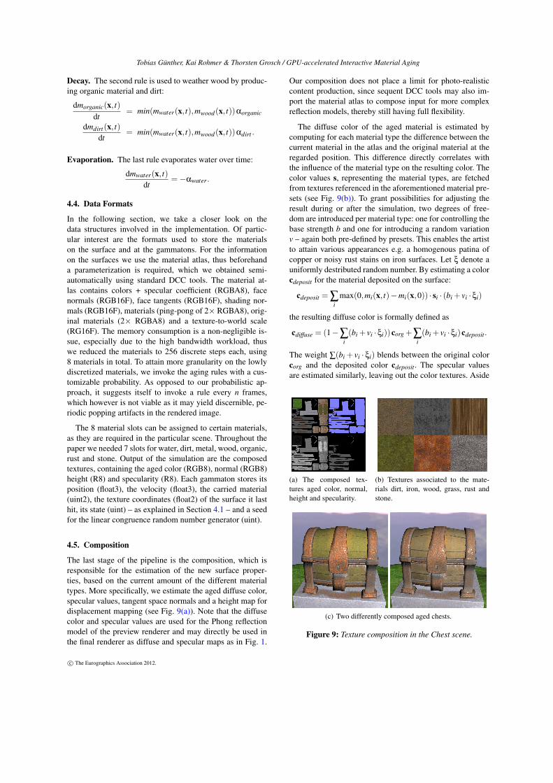
4.5. Composition
The last stage of the pipeline is the composition, which isresponsible for the estimation of the new surface proper-ties, based on the current amount of the different materialtypes. More specifically, we estimate the aged diffuse color,specular values, tangent space normals and a height map fordisplacement mapping (see Fig. 9(a)). Note that the diffusecolor and specular values are used for the Phong reflectionmodel of the preview renderer and may directly be used inthe final renderer as diffuse and specular maps as in Fig. 1.
Our composition does not place a limit for photo-realisticcontent production, since sequent DCC tools may also im-port the material atlas to compose input for more complexreflection models, thereby still having full flexibility.
The diffuse color of the aged material is estimated bycomputing for each material type the difference between thecurrent material in the atlas and the original material at theregarded position. This difference directly correlates withthe influence of the material type on the resulting color. Thecolor values s, representing the material types, are fetchedfrom textures referenced in the aforementioned material pre-sets (see Fig. 9(b)). To grant possibilities for adjusting theresult during or after the simulation, two degrees of free-dom are introduced per material type: one for controlling thebase strength b and one for introducing a random variationv – again both pre-defined by presets. This enables the artistto attain various appearances e.g. a homogenous patina ofcopper or noisy rust stains on iron surfaces. Let ξ denote auniformly destributed random number. By estimating a colorcdeposit for the material deposited on the surface:
cdeposit = ∑i
max(0,mi(x, t)−mi(x,0)) · si · (bi + vi ·ξi)
the resulting diffuse color is formally defined as
cdiffuse = (1−∑i(bi + vi ·ξi))corg +∑
i(bi + vi ·ξi)cdeposit.
The weight ∑(bi + vi · ξi) blends between the original colorcorg and the deposited color cdeposit. The specular valuesare estimated similarly, leaving out the color textures. Aside
(a) The composed tex-tures aged color, normal,height and specularity.
(b) Textures associated to the mate-rials dirt, iron, wood, grass, rust andstone.
(c) Two differently composed aged chests.
Figure 9: Texture composition in the Chest scene.
c© The Eurographics Association 2012.
Tobias Günther, Kai Rohmer & Thorsten Grosch / GPU-accelerated Interactive Material Aging
from the amounts of the different material types, one byte isreserved to store the overall material height, which is initial-ized with values from input height maps. In the compositionstage of the pipeline, the height is influenced by the amountof material on the surface, e.g by rust and organic, resultingin an output height map. Finally, we use the height map tocalculate tangent space normals.
5. User Interaction
The following section outlines the typical user interactionsundertaken during usage of our program. For convenience,our system allows the user to rearrange both the scene ob-jects (move, rotate and scale) and the gammaton emitters.Inspired from user interface concepts often found in sculpt-ing tools, we additionally allow the artist to paint on sur-faces by placing the emitter at the selected location with anoffset in normal direction, adjustable by scrolling the mousewheel. Furthermore, the variance from the normal direction(concentrated beam vs. drizzle) and the size of the emittercan be adjusted.
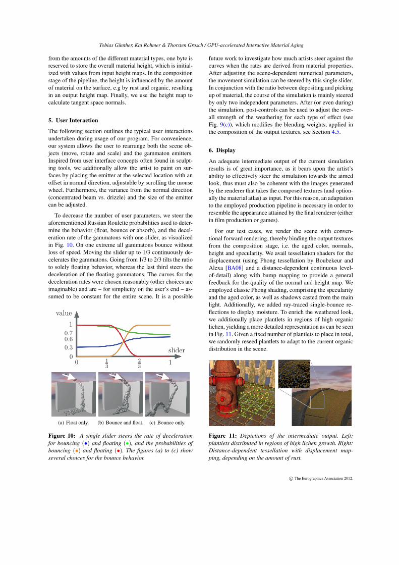
To decrease the number of user parameters, we steer theaforementioned Russian Roulette probabilities used to deter-mine the behavior (float, bounce or absorb), and the decel-eration rate of the gammatons with one slider, as visualizedin Fig. 10. On one extreme all gammatons bounce withoutloss of speed. Moving the slider up to 1/3 continuously de-celerates the gammatons. Going from 1/3 to 2/3 tilts the ratioto solely floating behavior, whereas the last third steers thedeceleration of the floating gammatons. The curves for thedeceleration rates were chosen reasonably (other choices areimaginable) and are – for simplicity on the user’s end – as-sumed to be constant for the entire scene. It is a possible
0 113
23
0.3
0.60.7
1
0slider
value
(a) Float only. (b) Bounce and float. (c) Bounce only.
Figure 10: A single slider steers the rate of decelerationfor bouncing (•) and floating (•), and the probabilities ofbouncing (•) and floating (•). The figures (a) to (c) showseveral choices for the bounce behavior.
future work to investigate how much artists steer against thecurves when the rates are derived from material properties.After adjusting the scene-dependent numerical parameters,the movement simulation can be steered by this single slider.In conjunction with the ratio between depositing and pickingup of material, the course of the simulation is mainly steeredby only two independent parameters. After (or even during)the simulation, post-controls can be used to adjust the over-all strength of the weathering for each type of effect (seeFig. 9(c)), which modifies the blending weights, applied inthe composition of the output textures, see Section 4.5.
6. Display
An adequate intermediate output of the current simulationresults is of great importance, as it bears upon the artist’sability to effectively steer the simulation towards the aimedlook, thus must also be coherent with the images generatedby the renderer that takes the composed textures (and option-ally the material atlas) as input. For this reason, an adaptationto the employed production pipeline is necessary in order toresemble the appearance attained by the final renderer (eitherin film production or games).
For our test cases, we render the scene with conven-tional forward rendering, thereby binding the output texturesfrom the composition stage, i.e. the aged color, normals,height and specularity. We avail tessellation shaders for thedisplacement (using Phong tessellation by Boubekeur andAlexa [BA08] and a distance-dependent continuous level-of-detail) along with bump mapping to provide a generalfeedback for the quality of the normal and height map. Weemployed classic Phong shading, comprising the specularityand the aged color, as well as shadows casted from the mainlight. Additionally, we added ray-traced single-bounce re-flections to display moisture. To enrich the weathered look,we additionally place plantlets in regions of high organiclichen, yielding a more detailed representation as can be seenin Fig. 11. Given a fixed number of plantlets to place in total,we randomly reseed plantlets to adapt to the current organicdistribution in the scene.
Figure 11: Depictions of the intermediate output. Left:plantlets distributed in regions of high lichen growth. Right:Distance-dependent tessellation with displacement map-ping, depending on the amount of rust.
c© The Eurographics Association 2012.
Tobias Günther, Kai Rohmer & Thorsten Grosch / GPU-accelerated Interactive Material Aging
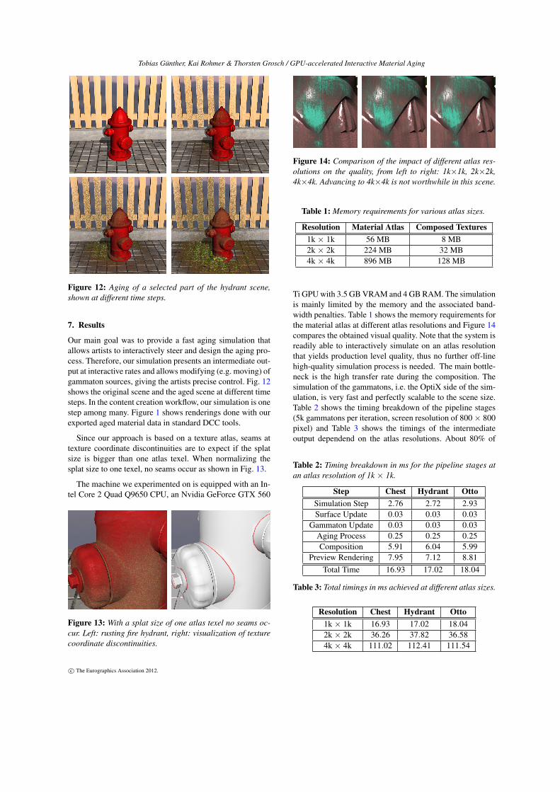
Figure 12: Aging of a selected part of the hydrant scene,shown at different time steps.
7. Results
Our main goal was to provide a fast aging simulation thatallows artists to interactively steer and design the aging pro-cess. Therefore, our simulation presents an intermediate out-put at interactive rates and allows modifying (e.g. moving) ofgammaton sources, giving the artists precise control. Fig. 12shows the original scene and the aged scene at different timesteps. In the content creation workflow, our simulation is onestep among many. Figure 1 shows renderings done with ourexported aged material data in standard DCC tools.
Since our approach is based on a texture atlas, seams attexture coordinate discontinuities are to expect if the splatsize is bigger than one atlas texel. When normalizing thesplat size to one texel, no seams occur as shown in Fig. 13.
The machine we experimented on is equipped with an In-tel Core 2 Quad Q9650 CPU, an Nvidia GeForce GTX 560
Figure 13: With a splat size of one atlas texel no seams oc-cur. Left: rusting fire hydrant, right: visualization of texturecoordinate discontinuities.
Figure 14: Comparison of the impact of different atlas res-olutions on the quality, from left to right: 1k×1k, 2k×2k,4k×4k. Advancing to 4k×4k is not worthwhile in this scene.
Table 1: Memory requirements for various atlas sizes.
Resolution Material Atlas Composed Textures1k × 1k 56 MB 8 MB2k × 2k 224 MB 32 MB4k × 4k 896 MB 128 MB
Ti GPU with 3.5 GB VRAM and 4 GB RAM. The simulationis mainly limited by the memory and the associated band-width penalties. Table 1 shows the memory requirements forthe material atlas at different atlas resolutions and Figure 14compares the obtained visual quality. Note that the system isreadily able to interactively simulate on an atlas resolutionthat yields production level quality, thus no further off-linehigh-quality simulation process is needed. The main bottle-neck is the high transfer rate during the composition. Thesimulation of the gammatons, i.e. the OptiX side of the sim-ulation, is very fast and perfectly scalable to the scene size.Table 2 shows the timing breakdown of the pipeline stages(5k gammatons per iteration, screen resolution of 800× 800pixel) and Table 3 shows the timings of the intermediateoutput dependend on the atlas resolutions. About 80% of
Table 2: Timing breakdown in ms for the pipeline stages atan atlas resolution of 1k × 1k.
Step Chest Hydrant OttoSimulation Step 2.76 2.72 2.93Surface Update 0.03 0.03 0.03
Gammaton Update 0.03 0.03 0.03Aging Process 0.25 0.25 0.25Composition 5.91 6.04 5.99
Preview Rendering 7.95 7.12 8.81Total Time 16.93 17.02 18.04
Table 3: Total timings in ms achieved at different atlas sizes.
Resolution Chest Hydrant Otto1k × 1k 16.93 17.02 18.042k × 2k 36.26 37.82 36.584k × 4k 111.02 112.41 111.54
c© The Eurographics Association 2012.
Tobias Günther, Kai Rohmer & Thorsten Grosch / GPU-accelerated Interactive Material Aging
the preview rendering costs originate in the brute-force re-flection rendering, which can be improved or avoided if notneeded. Also note that the preview rendering and the com-position – which are both the slowest components – are op-tional to the simulation. Breaking the composition down, tobe carried out over a span of a few frames, and employinga more sophisticated and optimized renderer allows to ad-just to the narrow time budget of real-time applications, e.g.modern games.
8. Conclusion and Future Work
In this paper, we presented the first interactive material ag-ing simulation by tracing gammatons on the GPU. We em-ployed a simple set of rules to achieve the most commonaging effects (e.g. dirt, rust, organic and water precipitate)and displayed those in a few seconds in which the scene pro-gressively and visibly ages. Additionally, we used user in-teraction techniques known from sculpting for the adding offiligree detail, thereby allowing to directly steer and designthe aging process.
Yet open to further research is the simulation on largescenes. Currently, our approach is limited to a few objects(chosen by the artist as a region of interest), as the mem-ory requirements for the material atlas limit the quality ofthe simulation. Possible out-of-core approaches to considerare presented by Lefebvre et al. [LDN04] and virtual textur-ing [vW09]. A number of extensions to our approach areimaginable. If more memory was available (e.g. by com-pressions), it would be possible to add multiple layers ofmaterial, not only one as we do now. Stack-based terrains[LMS11] are a possible source of inspiration. Accompaniedwith this is the gradual peeling of the layers, possibly ini-tiating a more distinctive deformation of the surface, whichcould go beyond the capabilities of single-pass tessellationshaders. Another important step is the implementation of amore detailed temporal aging behavior, since many materialsare subject to a non-linear aging process [GTR∗06].
References[BA08] BOUBEKEUR T., ALEXA M.: Phong tessellation. ACM
Transactions on Graphics 27, 5 (Dec. 2008), 141:1–141:5. 6
[BPMG04] BOSCH C., PUEYO X., MERILLOU S., GHAZAN-FARPOUR D.: A Physically-Based Model for Rendering RealisticScratches. Computer Graphics Forum 23, 3 (2004), 361–370. 2
[CPK06] COLBERT M., PATTANAIK S., KRIVANEK J.: BRDF-shop: creating physically correct bidirectional reflectance distri-bution functions. IEEE Computer Graphics and Applications 26,1 (2006), 30–36. 2
[CXW∗05] CHEN Y., XIA L., WONG T.-T., TONG X., BAO H.,GUO B., SHUM H.-Y.: Visual Simulation of Weathering byGammaton Tracing. ACM Transactions on Graphics 24 (2005),1127–1133. 2
[DEJ∗99] DORSEY J., EDELMAN A., JENSEN H. W., LEGAKISJ., PEDERSEN H. K. H.: Modeling and rendering of weatheredstone. ACM Transactions on Graphics, Annual Conference Se-ries (1999), 225–234. 2
[DGA04] DESBENOIT B., GALIN E., AKKOUCHE S.: Simulat-ing and modeling lichen growth. Computer Graphics Forum 23,3 (2004), 341–350. 2
[DH96] DORSEY J., HANRAHAN P.: Modeling and Renderingof Metallic Patinas. In SIGGRAPH (1996), vol. 30, ACM Press,pp. 387–396. 2
[DPH96] DORSEY J., PEDERSEN H. K. H., HANRAHAN P.:Flow and Changes in Appearance. In SIGGRAPH (1996),vol. 30, ACM, pp. 411–420. 2
[GC01] GOBRON S., CHIBA N.: Crack pattern simulation basedon 3D surface cellular automata. The Visual Computer 17, 5(2001), 287–309. 2
[GTR∗06] GU J., TU C., RAMAMOORTHI R., BELHUMEUR P.,MATUSIK W., NAYAR S.: Time-varying surface appearance: ac-quisition, modeling and rendering. ACM Transactions on Graph-ics 25, 3 (2006), 762–771. 2, 8
[HH90] HANRAHAN P., HAEBERLI P.: Direct WYSIWYG paint-ing and texturing on 3D shapes. SIGGRAPH 24, 4 (1990), 215–223. 2
[HTK98] HIROTA K., TANOUE Y., KANEKO T.: Generation ofcrack patterns with a physical model. The Visual Computer 14(1998), 126–187. 2
[HTK00] HIROTA K., TANOUE Y., KANEKO T.: Simulation ofthree-dimensional cracks. The Visual Computer 16, 7 (2000),371–378. 2
[KRB11] KIDER J. T., RAJA S., BADLER N. I.: Fruit Senescenceand Decay Simulation. Computer Graphics Forum 30, 2 (2011),257–266. 2
[LDN04] LEFEBVRE S., DARBON J., NEYRET F.: Unified Tex-ture Management for Arbitrary Meshes. Rapport de rechercheRR-5210, INRIA, 2004. 8
[LMS11] LÖFFLER F., MÜLLER A., SCHUMANN H.: Real-timeRendering of Stack-based Terrains. In VMV (2011), pp. 161–168.8
[MDG01] MERILLOU S., DISCHLER J.-M., GHAZANFARPOURD.: Corrosion: Simulating and Rendering. In Graphics Interface(2001). 2
[MG08] MERILLOU S., GHAZANFARPOUR D.: A survey of ag-ing and weathering phenomena in computer graphics. Computers& Graphics 32, 2 (2008), 159–174. 2
[PBD∗10] PARKER S. G., BIGLER J., DIETRICH A.,FRIEDRICH H., HOBEROCK J., LUEBKE D., MCALLIS-TER D., STICH M.: OptiX : A General Purpose Ray TracingEngine. ACM Transactions on Graphics 29, 4 (2010), 1–13. 3
[PPD01] PAQUETTE E., POULIN P., DRETTAKIS G.: SurfaceAging by Impacts. Graphics Interface (2001), 175–182. 2
[PPD02] PAQUETTE E., POULIN P., DRETTAKIS G.: The Simu-lation of Paint Cracking and Peeling. Graphics Interface (2002),59–68. 2
[vW09] VAN WAVEREN J.: id tech 5 challenges - from texturevirtualization to massive parallelization. In SIGGRAPH 2009 Be-yond Programmable Shading course (2009). 8
[WNH97] WONG T.-T., NG W.-Y., HENG P.-A.: A GeometryDependent Texture Generation Framework for Simulating Sur-face Imperfections. In Eurographics Rendering Workshop 1997(1997), Springer-Verlag, pp. 139–150. 2
[WTL∗06] WANG J., TONG X., LIN S., PAN M., WANG C.,BAO H., GUO B., SHUM H.-Y.: Appearance manifolds for mod-eling time-variant appearance of materials. ACM Transactions onGraphics 25, 3 (2006), 754. 2
c© The Eurographics Association 2012.