Embed Size (px)
Citation preview
GPS machine guidance
in construction equipment
Daði Hrannar Aðalsteinsson
Construction technology
Supervisory teacher: Guðbrandur Steinþórsson School of Science and Engineering

DHA Final project BSc.
2
Instructor: Guðbrandur Steinþórsson Spring 2008 School of Science and Engineering
Name of project: GPS machine guidance in construction equipment
Course: Construction technology Type of project. Construction
Term: Spring Course: : BT LOK1012
Summary
The aim of this project is to compare the performance of a excavator with GPS guidance system on the one hand and on the other hand a excavator in same type of work, which was done the traditional way and with surveying. A predetermined construction job was performed. i.e. the digging of trench in two different ways.
On one hand a surveyor performed the surveying needed before the job was performed, and while it was done, and the excavator was working according to those measurements and stakes. On the other hand the same job was performed by a excavator which was equipped with GPS machine guidance and no surveying performed by surveyors, but the job was preformed according to a model of the project, which was loaded into the machine equipment. Both jobs were monitored with precise measuring equipment. The outcome was measurable realistic comparison of two work procedures on comparable work, regarding time, material and productivity. The outcome should tell contractors whether GPS machine guidance is optimal and leading to increased profitability.
Author: Daði Hrannar Aðalsteinsson
Supervisory teacher: Guðbrandur Steinþórsson
Instructor: Guðbrandur Steinþórsson
Company/institution:
Íslenskir aðalverktakar
Ísmar
Date: Keywords Icelandic: Keywords English:
07.05.2008 GPS, Vélstýring, mælingar. GPS, Machine control, Surveying.
Distribution:
open
closed
to:

DHA Final project BSc.
3
Foreword
The first idea on this project was after a conversation with Sigurdur Sigurdsson, director of Íslenskir aðalverktakar (Iceland Prime Contractor). Then the question "how much is GPS machine guidance in a construction equipment saving?". By checking this no clear response was available, only speculation on savings from the manufacturer of the equipment. It was thought to be interesting to get this clear by accurate comparison measurements within a specific project. Ísmar, the sales partner for Trimble GPS machine guidance systems in Iceland, was contacted and they did express high interest. In continuation of that it was decided to work on a final paper, where comparison would be done on GPS machine guidance systems and traditional surveying, where the outcome of this question would be sought after.
I do want to express my thanks to Íslenskir aðalverktakar, Ísmar and Hekla for given confidence and all the help when working at this final paper. Furthermore I do specially want to thank Jón Tryggvi Helgason, Sæmundur Sævarsson and Sigurjón Hrafnkelsson.
Daði Hrannar Aðalsteinsson
Reykjavík May 7th 2008.
DHA Final project BSc.
4
Table of contents
Foreword 3
Table of contents 4
1. Introduction 7
2 Execution 8
2.1 Preparation for execution 8
2.1.1 Negotiation with supporting parties 8
2.1.2 Equipment and tools 9
2.1.2.1 The machine 9
2.1.2.2 Measuring equipment 10
2.1.2.3 Control measurements 11
2.1.3 The site 12
2.1.4 Measurements 13
2.1.5 Trenches 14
2.1.6 Data processing 15
2.1.6.1 Panorama 15
2.1.6.2 File on coordinates 16
2.1.6.3 Center line for both trenches 16
Heights for bottom of both trenches 17
2.1.6.4 Cross-section of both trenches 17
2.1.6.5 Quantities 18
2.2 The project 19
2.2.1 The project part 20
2.2.1.1 Data prepared for arrangement 20
2.2.2 The project performed 21
2.2.2.1 A trench excavated the traditional way 21
2.2.2.2 A trench excavated the new way 26
2.2.3 Control measurements with Universal Total station 29
2.2.3.1 Installation of Universal Total station 29
DHA Final project BSc.
5
2.2.3.2 Trenches scanned 30
2.2.3.3 Processing of measurements of trenches 31
2.2.4 Processing of findings 32
3 Findings 33
3.1 Time 33
3.2 Use of oil 33
3.3 Surveyor 34
3.4 Removal 34
3.5 Fill 35
3.6 Work effort 35
3.6.1 Digging of trench 35
3.7 Statistics 36
3.7.1 Removal 37
3.7.2 Fill 38
3.7.3 Deviation in area 40
3.7.4 Deviation in height 41
4 Discussion and interpretation 42
4.1 Advantages and shortcomings of GPS machine guidance 42
4.1.1 For the excavator operator 42
4.1.1.1 The excavator operator opinion on the GPS machine guidance. 42
4.1.1.1.1 Installation 42
4.1.1.1.2 Usage 43
4.1.2 For the surveyor 43
4.1.3 For the company 43
4.2 Suitability of GPS machine guidance 43
4.2.1 General 43
4.2.2 At different jobs 44
4.3 Notes on the assignment 44
4.3.1 Difficult situations 44
DHA Final project BSc.
6
4.3.2 Short duration of operations 45
5 Summary 46
6 References 47
Appendixes 49
1 Measurements 49
1.2 History of surveying 49
1.3 History of surveying in Iceland 49
1.4 Angle measurement 49
1.5 Ellipsoid and geoid 50
1.6 Projections 51
1.7 System of Universal Total Stations 51
1.8 WGS84 52
1.9 ÍSNET93 53
2 Measuring equipment 57
2.1 Overview 57
1. Laser-equipment 57
2. Universal Total station with remote control (single user station) 58
3. GPS - satellite measurements 59
3 Machine guidance 62
3.1 History of machine guidance 62
3.2 Machine guidance in general 62
3.3 Machine guidance with laser 62
3.4 Machine guidance with Universal Total station 63
3.5 Machine guidance with GPS 63
4 Installation of GPS machine guidance in a excavator for the assignment 64
5 Opinion 67
5.1 Contractors opinion on usage of machine guidance in construction equipment. 67
DHA Final project BSc.
7
1. Introduction
GPS machine guidance for use in construction equipment was first sold in Iceland in year 2000 for use in a road grader and a bulldozer for road construction in Mývatnsöræfi (in Northern-Iceland).
Since that year the sales has risen a great deal, and now it is estimated that approx. 100 machine guidance systems are in use in Iceland. Research on the profitability of machine guidance are not many, but Caterpillar did one such on their exercise location in Spain 2006. (Caterpillar, 2006b). That assignment did include digging for a road and filling in again with base layer material. This experiment did show tremendous superiority of machine guidance compared with traditional methods. The demand for profitability have risen to a great deal over the last years and many companies use much time and investment to investigate opportunities to improve their profitability. The main purpose of this assignment is to calculate the profitability of investing in GPS machine guidance. To measure the profitability same type of job was performed two times but with different methods.
The traditional way was a work procedure as has been used in this country for many years. A surveyor gets data for surveying, for example a ditch, foundations for a house or a road. The surveyor prepares the data for the measuring equipment and performs the surveying. The job is performed based on this surveying.
The new way implies, as the traditional way, that the surveyor gets data for surveying. The surveyor prepares the data for the surveying equipment, but instead of do the measuring himself, he sends the data to the construction machine, which performs the surveying and the job on site.
From now on we talk of the traditional way, where all the measurements are done by a surveyor with a GPS measuring equipment.
The other way is called the new way and there all the measurements are done by a GPS machine guidance.
The assignment did incorporate digging of two 160 meters long trenches, one by each way. To compare the methods all the time which was used to perform those two jobs was logged. Furthermore the use of fuel, excavation of landfill and filling in of sand under laying was measured to get the best comparison.
Following manpower did participate in the project at the site:
Daði Aðalsteinsson Projcet manager - Surveyor - Time keeper Kári Rúnarsson Operator - Time keeper - Photographer - Assistant Kristinn Eiðsson Myndataka - Assistant Jón Tryggvi Helgason Assistant Sæmundur Sævarsson Myndataka - Assistant Sigurjón Hrafnkelsson Assistant
DHA Final project BSc.
8
2 Operation
2.1 Preparation for execution
2.1.1 Negotiation with supporting parties
Íslenskir aðalverktakar (Iceland Prime Contractor) did lend a excavator and a operator for the project. The excavator was Caterpillar 330DL and a permission was given for the work of the operator for 5 days plus two and half days for installing the equipment. Íslenskir aðalverktakar (Iceland Prime Contractor) did perform the transport and undertake insurance of machine and operator while the project was performed. Th company did also include oil and lubrication of the machine during the lend period.
Ísmar did lend Trimble GPS 3D system, type GCS900, for an excavator, for the project Ísmar did care for the installation of the equipment and training of the operator for the project. Ísmar did also supply measuring equipment so comparison measurements could be done on site and the insurance of the equipment.
Hekla did lend control equipment for use in the excavator for the project. Hekla did assist in processing of the data from the control system. Hekla did insure their equipment while the project lasted.
DHA Final project BSc.
9
2.1.2 Equipment and tools
2.1.2.1 The machine
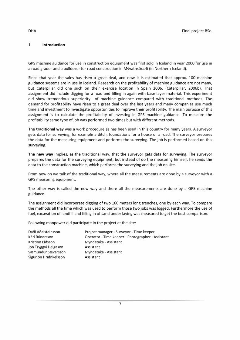
Caterpillar 330DL Hydraulic Excavator.
Picture 1. Here the main data on the excavator which was used in the project.
DHA Final project BSc.
10
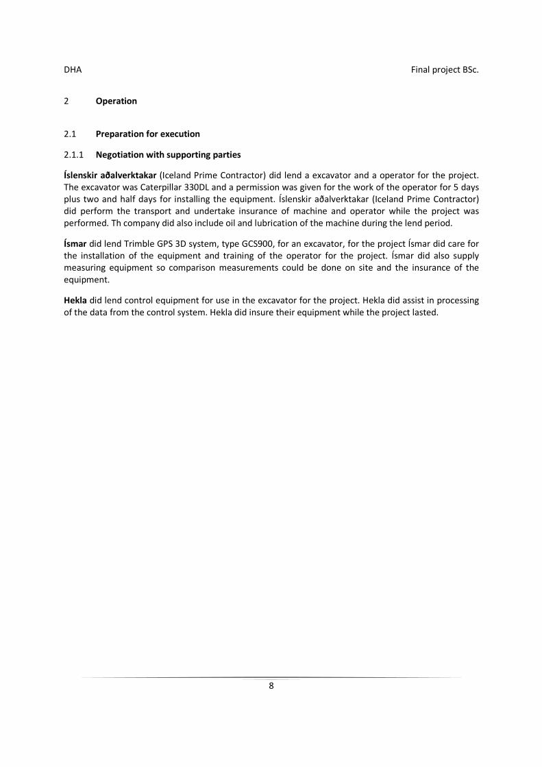
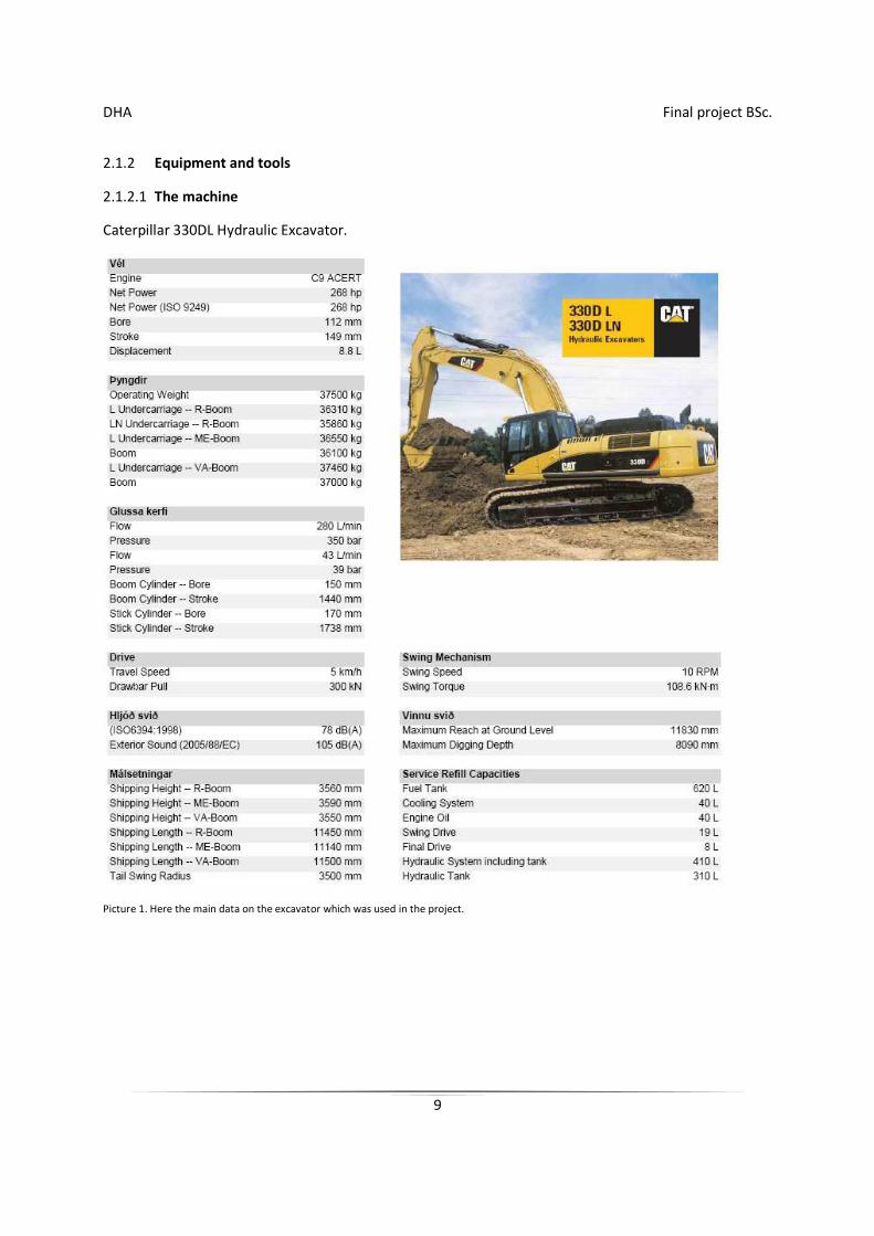
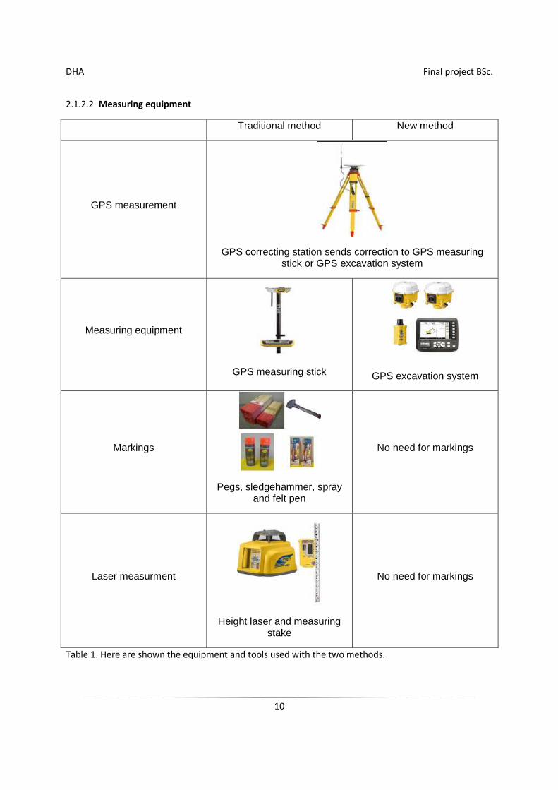
2.1.2.2 Measuring equipment
Traditional method New method
GPS measurement
GPS correcting station sends correction to GPS measuring stick or GPS excavation system
Measuring equipment
GPS measuring stick
GPS excavation system
Markings
Pegs, sledgehammer, spray and felt pen
No need for markings
Laser measurment
Height laser and measuring stake
No need for markings
Table 1. Here are shown the equipment and tools used with the two methods.
DHA Final project BSc.
11
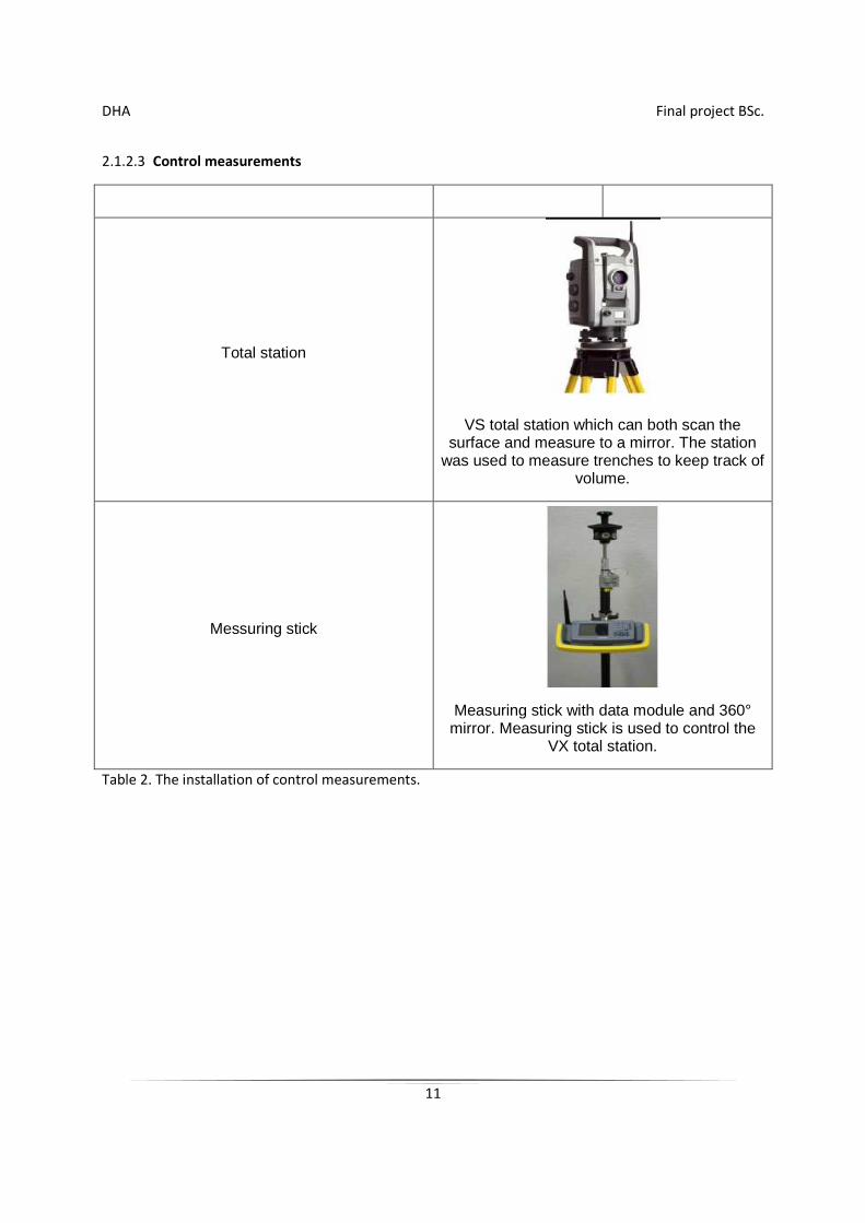
2.1.2.3 Control measurements
Total station
VS total station which can both scan the surface and measure to a mirror. The station
was used to measure trenches to keep track of volume.
Messuring stick
Measuring stick with data module and 360° mirror. Measuring stick is used to control the
VX total station.
Table 2. The installation of control measurements.
DHA Final project BSc.
12
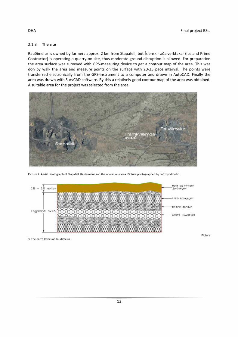
2.1.3 The site
Rauðimelur is owned by farmers approx. 2 km from Stapafell, but Íslenskir aðalverktakar (Iceland Prime Contractor) is operating a quarry on site, thus moderate ground disruption is allowed. For preparation the area surface was surveyed with GPS-measuring device to get a contour map of the area. This was don by walk the area and measure points on the surface with 20-25 pace interval. The points were transferred electronically from the GPS-instrument to a computer and drawn in AutoCAD. Finally the area was drawn with SurvCAD software. By this a relatively good contour map of the area was obtained. A suitable area for the project was selected from the area.
Picture 2. Aerial photograph of Stapafell, Rauðimelur and the operations area. Picture photographed by Loftmyndir ehf.
Picture 3. The earth layers at Rauðimelur.
DHA Final project BSc.
13
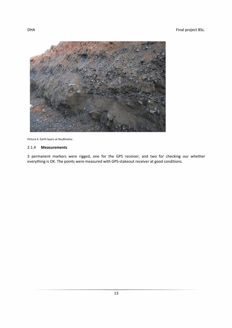
Picture 4. Earth layers at Rauðimelur.
2.1.4 Measurements
3 permanent markers were rigged, one for the GPS receiver, and two for checking our whether everything is OK. The points were measured with GPS-stakeout receiver at good conditions.
DHA Final project BSc.
14
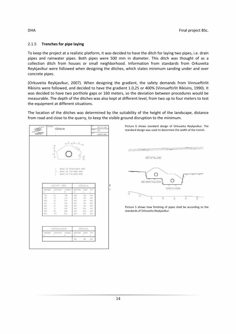
2.1.5 Trenches for pipe laying
To keep the project at a realistic platform, it was decided to have the ditch for laying two pipes, i.e. drain pipes and rainwater pipes. Both pipes were 500 mm in diameter. This ditch was thought of as a collection ditch from houses or small neighborhood. Information from standards from Orkuveita Reykjavíkur were followed when designing the ditches, which states minimum sanding under and over concrete pipes.
(Orkuveita Reykjavíkur, 2007). When designing the gradient, the safety demands from Vinnueftirlit Ríkisins were followed, and decided to have the gradient 1.0,25 or 400% (Vinnueftirlit Ríkisins, 1990). It was decided to have two porthole gaps or 160 meters, so the deviation between procedures would be measurable. The depth of the ditches was also kept at different level, from two up to four meters to test the equipment at different situations.
The location of the ditches was determined by the suitability of the height of the landscape, distance from road and close to the quarry, to keep the visible ground disruption to the minimum.
Picture 6 shows standard design of Orkuveita Reykjavíkur. The standard design was used to determine the width of the trench.
Picture 5 shows how finishing of pipes shall be according to the standards of Orkuveita Reykjavíkur.
DHA Final project BSc.
15
2.1.6 Data processing
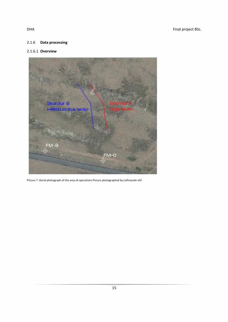
2.1.6.1 Overview
Picture 7. Aerial photograph of the area of operations Picture photographed by Loftmyndir ehf.
DHA Final project BSc.
16
2.1.6.2 List of coordinates
Austur Norður Hæð Fixed marker FM-C 328586.892 384136.936 23.705 Trench A sk11 328566.575 384170.925 21.300 sk12 328523.754 384238.500 19.300 sk13 328454.757 384278.989 16.200 Trench B sk31 328541.165 384162.181 21.300 sk32 328498.344 384229.755 19.300 sk33 328429.347 384270.245 16.200
Table 3 shows list of coordinates in ÍSNET93 coordinates.
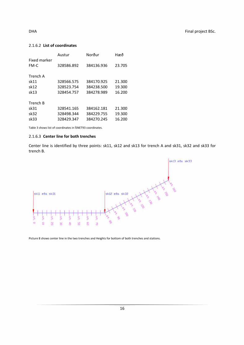
2.1.6.3 Center line for both trenches
Center line is identified by three points: sk11, sk12 and sk13 for trench A and sk31, sk32 and sk33 for trench B.
Picture 8 shows center line in the two trenches and Heights for bottom of both trenches and stations.
DHA Final project BSc.
17
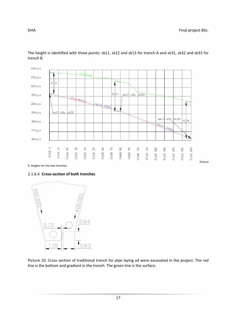
The height is identified with three points: sk11, sk12 and sk13 for trench A and sk31, sk32 and sk33 for trench B.
Picture 9. Heights for the two trenches.
2.1.6.4 Cross-section of both trenches
Picture 10. Cross section of traditional trench for pipe laying ad were excavated in the project. The red line is the bottom and gradient in the trench. The green line is the surface.

DHA Final project BSc.
18
2.1.6.5 Quantities
Estimated quantities according to calculations from Trimble Geomatics office (TGO).
Trench for pipe laying Removal
A 1250m3
B 1250m3
DHA Final project BSc.
19
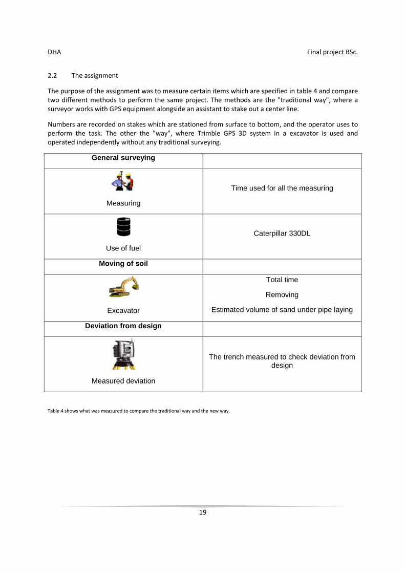
2.2 The assignment
The purpose of the assignment was to measure certain items which are specified in table 4 and compare two different methods to perform the same project. The methods are the "traditional way", where a surveyor works with GPS equipment alongside an assistant to stake out a center line.
Numbers are recorded on stakes which are stationed from surface to bottom, and the operator uses to perform the task. The other the "way", where Trimble GPS 3D system in a excavator is used and operated independently without any traditional surveying.
General surveying
Measuring
Time used for all the measuring
Use of fuel
Caterpillar 330DL
Moving of soil
Excavator
Total time
Removing
Estimated volume of sand under pipe laying
Deviation from design
Measured deviation
The trench measured to check deviation from design
Table 4 shows what was measured to compare the traditional way and the new way.
DHA Final project BSc.
20
2.2.1 The project part
2.2.1.1 Data prepared for arrangement
The trenches were placed in AutoCAD on a AutoCAD drawing. The height was determined by a contour map of the area. The data for the project was prepared in TGO, which is software which accompanies Trimble measuring equipment and machine guidance.
Picture 11 shows screen from the TGO software. On the picture can be seen where to got to road line mode.
In the beginning there is a need for determine the center line, more often the drain line is used. The line is defined by entering a coordinate on each point on the line. The point’s sk11, sk12 and sk13 were entered for ditch A and point’s sk31, sk32 and sk33 for ditch B.
Points are entered into TGO by registering east and north coordinate for each point. As a benefit it is also good to enter also the height.
Then those points are moved into road link mode in TGO. In the beginning a new road is chosen, it named and then choose line of road (horizontal alignment). In the next window there is a possibility to draw a line from sk11 to sk12 and then from sk12 to sk13. Then the road line is ready. Next the vertical alignment for the trench can be chosen. It is entered manually and station and height for each point is registered.
For the first point we enter for example station 0 and height 21.3 m, the next station 80 and height 19,3 and then station 160 and height 16.2 m.
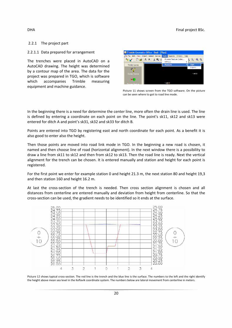
At last the cross-section of the trench is needed. Then cross section alignment is chosen and all distances from centerline are entered manually and deviation from height from centerline. So that the cross-section can be used, the gradient needs to be identified so it ends at the surface.
Picture 12 shows typical cross-section. The red line is the trench and the blue line is the surface. The numbers to the left and the right identify the height above mean sea level in the Keflavík coordinate system. The numbers below are lateral movement from centerline in meters.
DHA Final project BSc.
21
Next trench was then prepared in the same way. The volume of the trenches was then calculated to check if similar quantity of cubic meters were in both trenches. The data was exported to a small CF-card for the machine guidance and a logger for stationing.
2.2.2 The project performed
2.2.2.1 A trench excavated the traditional way
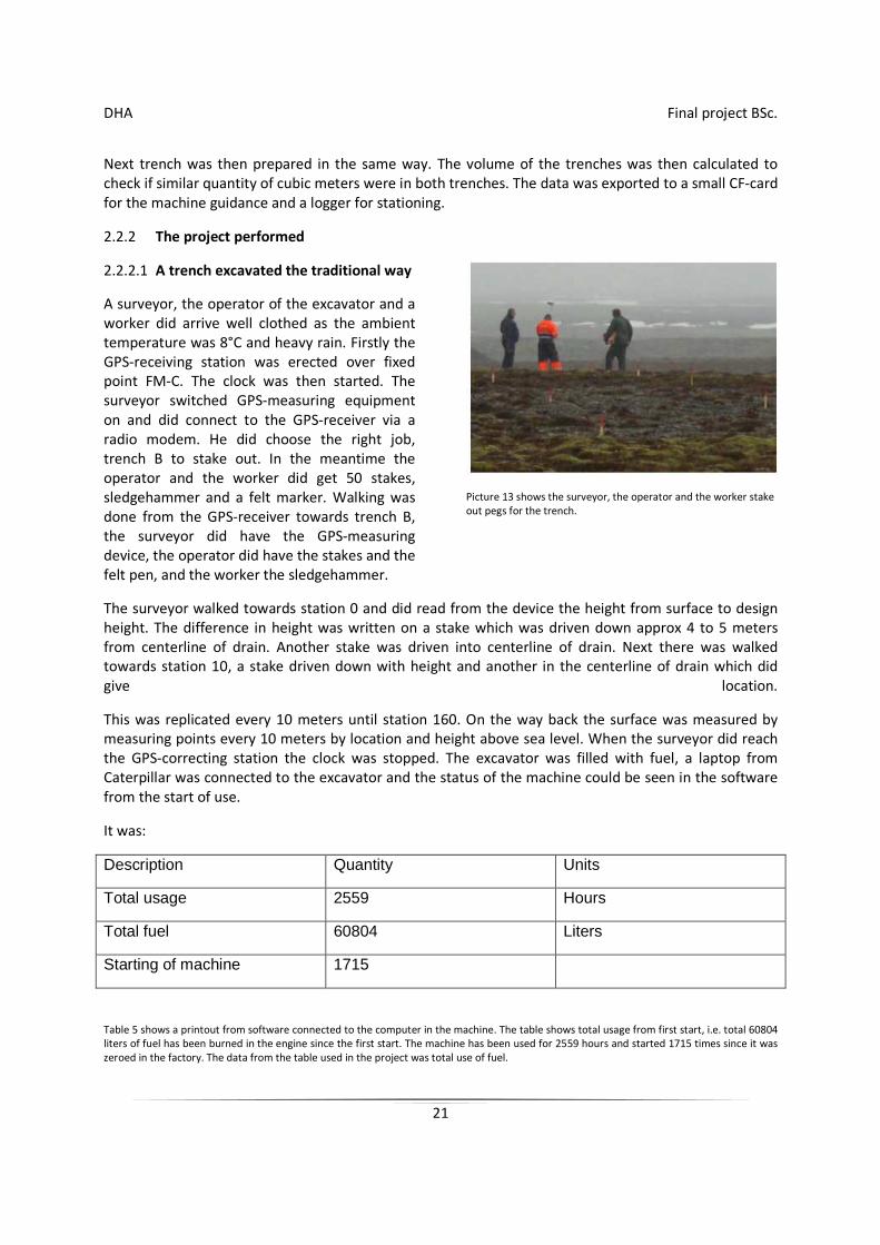
A surveyor, the operator of the excavator and a worker did arrive well clothed as the ambient temperature was 8°C and heavy rain. Firstly the GPS-receiving station was erected over fixed point FM-C. The clock was then started. The surveyor switched GPS-measuring equipment on and did connect to the GPS-receiver via a radio modem. He did choose the right job, trench B to stake out. In the meantime the operator and the worker did get 50 stakes, sledgehammer and a felt marker. Walking was done from the GPS-receiver towards trench B, the surveyor did have the GPS-measuring device, the operator did have the stakes and the felt pen, and the worker the sledgehammer.
Picture 13 shows the surveyor, the operator and the worker stake out pegs for the trench.
The surveyor walked towards station 0 and did read from the device the height from surface to design height. The difference in height was written on a stake which was driven down approx 4 to 5 meters from centerline of drain. Another stake was driven into centerline of drain. Next there was walked towards station 10, a stake driven down with height and another in the centerline of drain which did give location.
This was replicated every 10 meters until station 160. On the way back the surface was measured by measuring points every 10 meters by location and height above sea level. When the surveyor did reach the GPS-correcting station the clock was stopped. The excavator was filled with fuel, a laptop from Caterpillar was connected to the excavator and the status of the machine could be seen in the software from the start of use.
It was:
Description Quantity Units
Total usage 2559 Hours
Total fuel 60804 Liters
Starting of machine 1715
Table 5 shows a printout from software connected to the computer in the machine. The table shows total usage from first start, i.e. total 60804 liters of fuel has been burned in the engine since the first start. The machine has been used for 2559 hours and started 1715 times since it was zeroed in the factory. The data from the table used in the project was total use of fuel.
DHA Final project BSc.
22
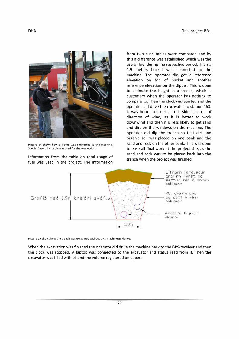
Picture 14 shows how a laptop was connected to the machine. Special Caterpillar cable was used for the connection.
Information from the table on total usage of fuel was used in the project. The information
from two such tables were compared and by this a difference was established which was the use of fuel during the respective period. Then a 1.9 meters bucket was connected to the machine. The operator did get a reference elevation on top of bucket and another reference elevation on the dipper. This is done to estimate the height in a trench, which is customary when the operator has nothing to compare to. Then the clock was started and the operator did drive the excavator to station 160. It was better to start at this side because of direction of wind, as it is better to work downwind and then it is less likely to get sand and dirt on the windows on the machine. The operator did dig the trench so that dirt and organic soil was placed on one bank and the sand and rock on the other bank. This was done to ease all final work at the project site, as the sand and rock was to be placed back into the trench when the project was finished.
Picture 15 shows how the trench was excavated without GPD machine guidance.
When the excavation was finished the operator did drive the machine back to the GPS-receiver and then the clock was stopped. A laptop was connected to the excavator and status read from it. Then the excavator was filled with oil and the volume registered on paper.
DHA Final project BSc.
23
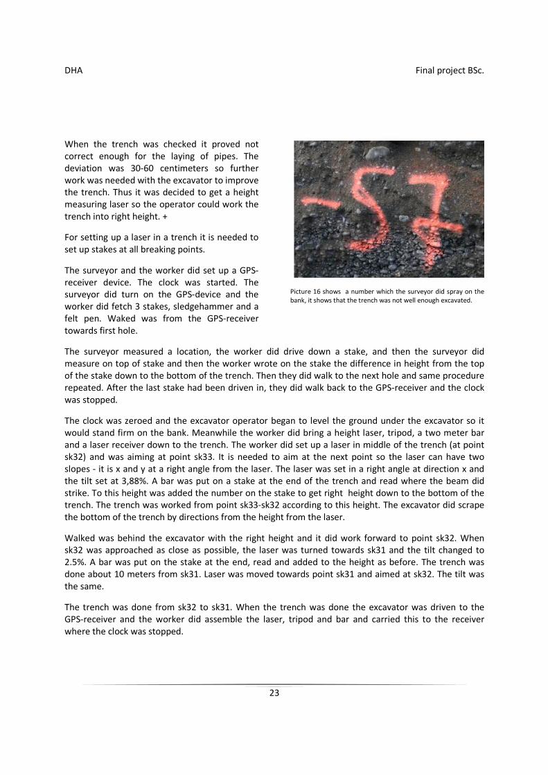
When the trench was checked it proved not correct enough for the laying of pipes. The deviation was 30-60 centimeters so further work was needed with the excavator to improve the trench. Thus it was decided to get a height measuring laser so the operator could work the trench into right height. +
For setting up a laser in a trench it is needed to set up stakes at all breaking points.
The surveyor and the worker did set up a GPS-receiver device. The clock was started. The surveyor did turn on the GPS-device and the worker did fetch 3 stakes, sledgehammer and a felt pen. Waked was from the GPS-receiver towards first hole.
Picture 16 shows a number which the surveyor did spray on the bank, it shows that the trench was not well enough excavated.
The surveyor measured a location, the worker did drive down a stake, and then the surveyor did measure on top of stake and then the worker wrote on the stake the difference in height from the top of the stake down to the bottom of the trench. Then they did walk to the next hole and same procedure repeated. After the last stake had been driven in, they did walk back to the GPS-receiver and the clock was stopped.
The clock was zeroed and the excavator operator began to level the ground under the excavator so it would stand firm on the bank. Meanwhile the worker did bring a height laser, tripod, a two meter bar and a laser receiver down to the trench. The worker did set up a laser in middle of the trench (at point sk32) and was aiming at point sk33. It is needed to aim at the next point so the laser can have two slopes - it is x and y at a right angle from the laser. The laser was set in a right angle at direction x and the tilt set at 3,88%. A bar was put on a stake at the end of the trench and read where the beam did strike. To this height was added the number on the stake to get right height down to the bottom of the trench. The trench was worked from point sk33-sk32 according to this height. The excavator did scrape the bottom of the trench by directions from the height from the laser.
Walked was behind the excavator with the right height and it did work forward to point sk32. When sk32 was approached as close as possible, the laser was turned towards sk31 and the tilt changed to 2.5%. A bar was put on the stake at the end, read and added to the height as before. The trench was done about 10 meters from sk31. Laser was moved towards point sk31 and aimed at sk32. The tilt was the same.
The trench was done from sk32 to sk31. When the trench was done the excavator was driven to the GPS-receiver and the worker did assemble the laser, tripod and bar and carried this to the receiver where the clock was stopped.
DHA Final project BSc.
24
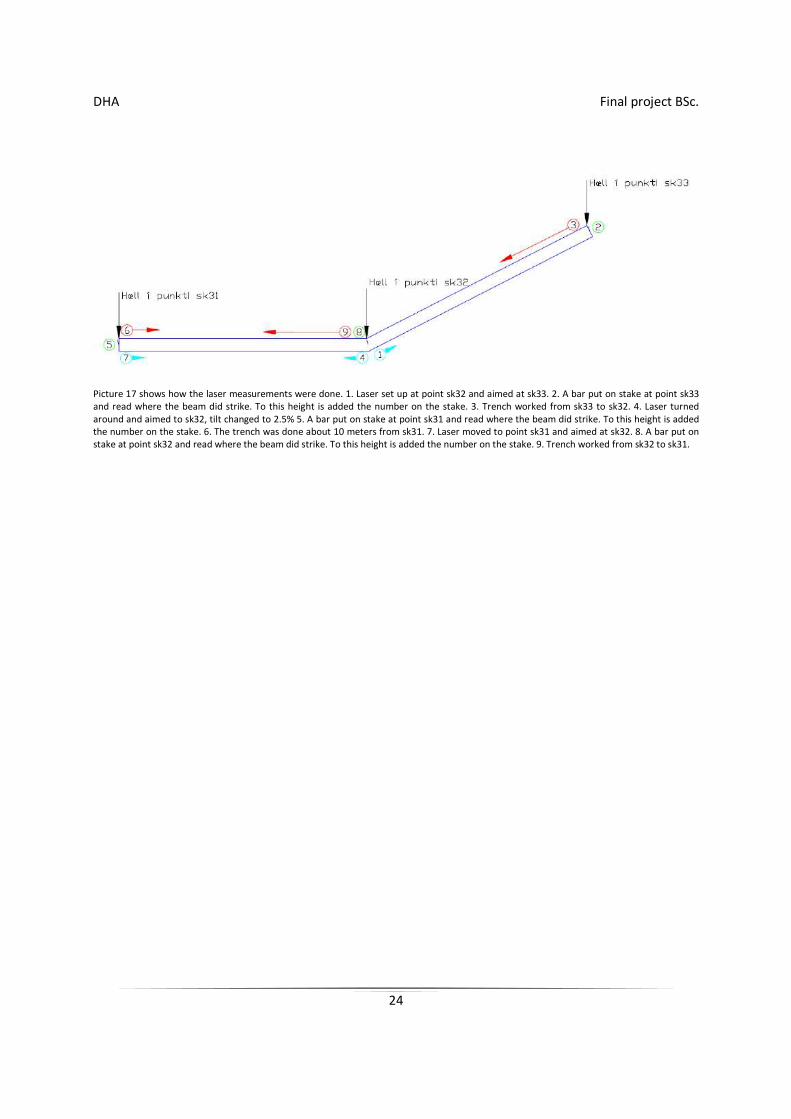
Picture 17 shows how the laser measurements were done. 1. Laser set up at point sk32 and aimed at sk33. 2. A bar put on stake at point sk33 and read where the beam did strike. To this height is added the number on the stake. 3. Trench worked from sk33 to sk32. 4. Laser turned around and aimed to sk32, tilt changed to 2.5% 5. A bar put on stake at point sk31 and read where the beam did strike. To this height is added the number on the stake. 6. The trench was done about 10 meters from sk31. 7. Laser moved to point sk31 and aimed at sk32. 8. A bar put on stake at point sk32 and read where the beam did strike. To this height is added the number on the stake. 9. Trench worked from sk32 to sk31.
DHA Final project BSc.
25
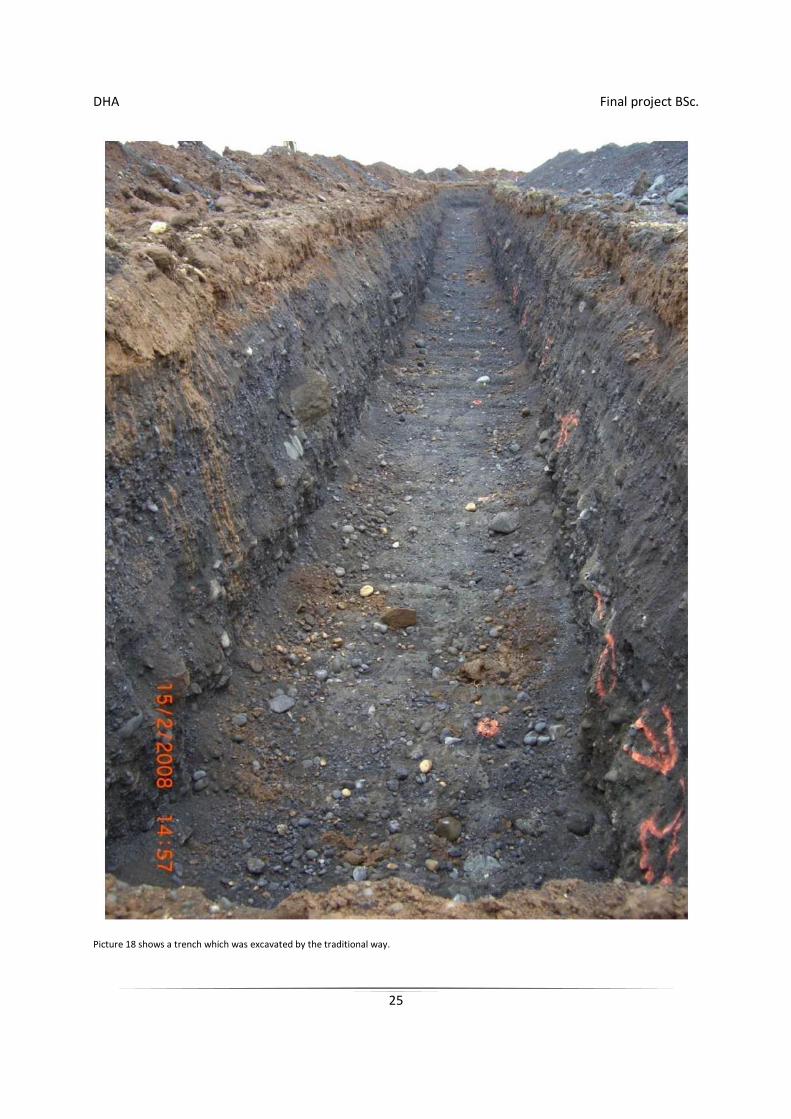
Picture 18 shows a trench which was excavated by the traditional way.
DHA Final project BSc.
26
2.2.2.2 A trench excavated the new way
The surveyor and the worker set up the GPS receiver and the clock was started. The surveyor did turn on the GPS-measurement device and the worker did fetch a stake, sledgehammer and a felt pen. Started was from GPS-receiver to station 0. The surveyor measured the location and the worker did drive down a stake. The surveyor did measure on top of stake and the worker wrote on the stake the difference in height from the top of the stake down to the bottom of the trench.
This was done to verify the accuracy of the system. Then back to the GPS-receiver where the clock was stopped.
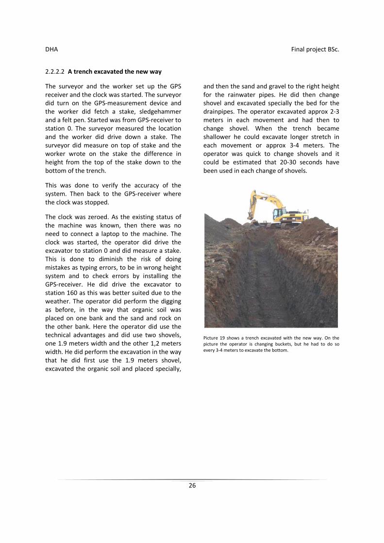
The clock was zeroed. As the existing status of the machine was known, then there was no need to connect a laptop to the machine. The clock was started, the operator did drive the excavator to station 0 and did measure a stake. This is done to diminish the risk of doing mistakes as typing errors, to be in wrong height system and to check errors by installing the GPS-receiver. He did drive the excavator to station 160 as this was better suited due to the weather. The operator did perform the digging as before, in the way that organic soil was placed on one bank and the sand and rock on the other bank. Here the operator did use the technical advantages and did use two shovels, one 1.9 meters width and the other 1,2 meters width. He did perform the excavation in the way that he did first use the 1.9 meters shovel, excavated the organic soil and placed specially,
and then the sand and gravel to the right height for the rainwater pipes. He did then change shovel and excavated specially the bed for the drainpipes. The operator excavated approx 2-3 meters in each movement and had then to change shovel. When the trench became shallower he could excavate longer stretch in each movement or approx 3-4 meters. The operator was quick to change shovels and it could be estimated that 20-30 seconds have been used in each change of shovels.
Picture 19 shows a trench excavated with the new way. On the picture the operator is changing buckets, but he had to do so every 3-4 meters to excavate the bottom.
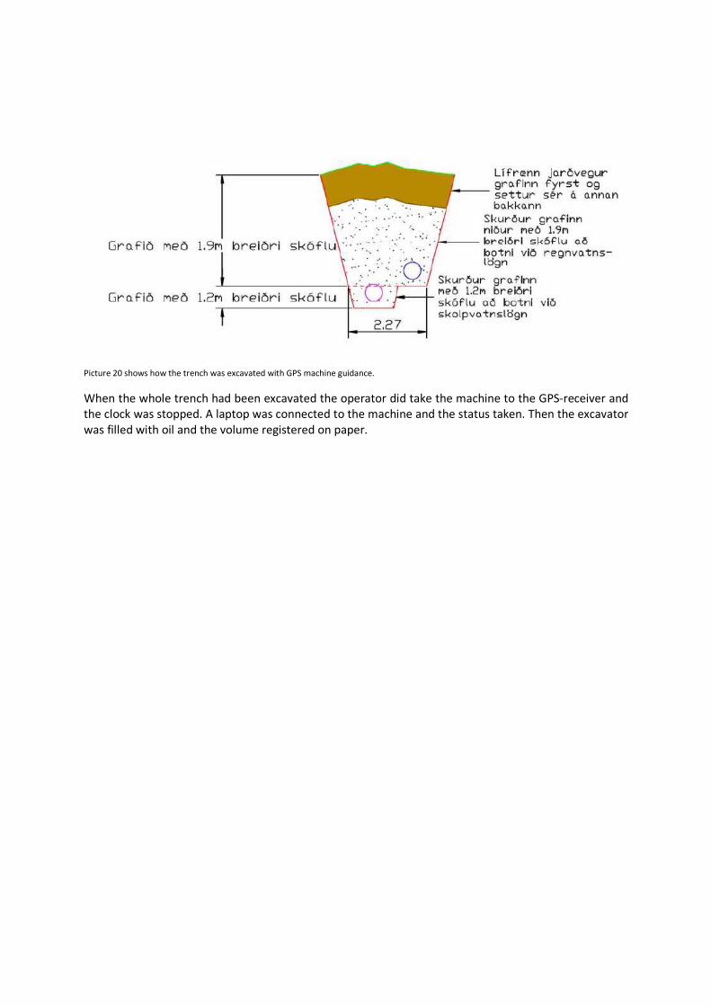
Picture 20 shows how the trench was excavated with GPS machine guidance.
When the whole trench had been excavated the operator did take the machine to the GPS-receiver and the clock was stopped. A laptop was connected to the machine and the status taken. Then the excavator was filled with oil and the volume registered on paper.
DHA Final project BSc.
28
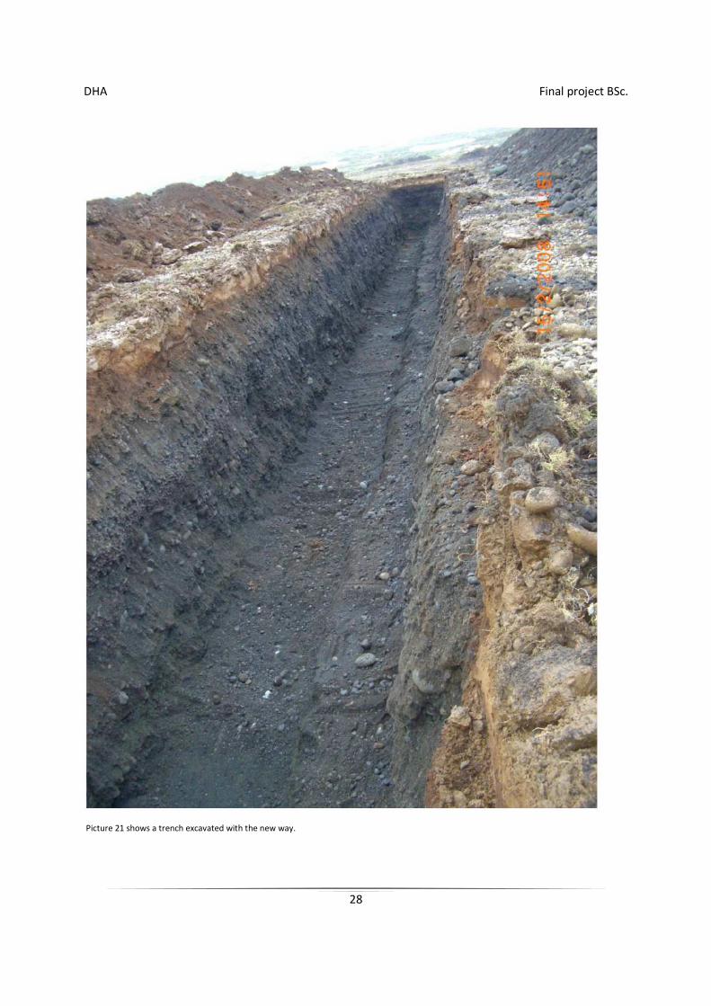
Picture 21 shows a trench excavated with the new way.
DHA Final project BSc.
29
2.2.3 Control measurements with Universal Total station
2.2.3.1 Setup of Universal Total station
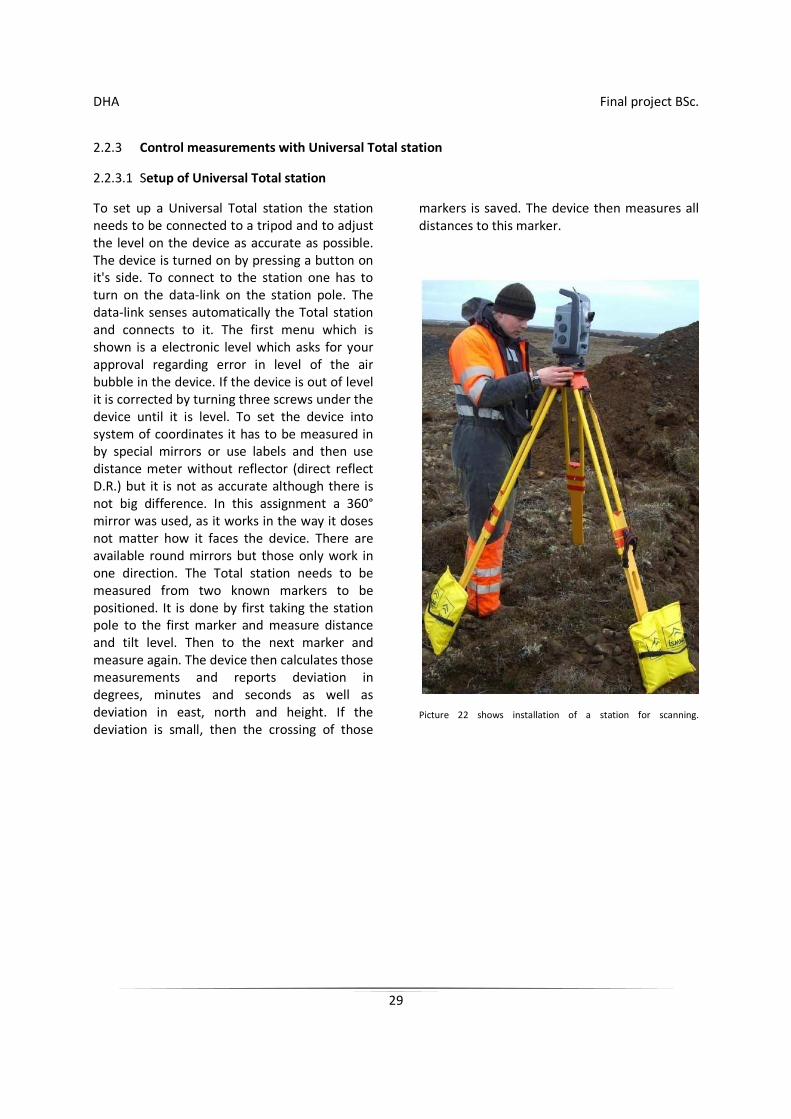
To set up a Universal Total station the station needs to be connected to a tripod and to adjust the level on the device as accurate as possible. The device is turned on by pressing a button on it's side. To connect to the station one has to turn on the data-link on the station pole. The data-link senses automatically the Total station and connects to it. The first menu which is shown is a electronic level which asks for your approval regarding error in level of the air bubble in the device. If the device is out of level it is corrected by turning three screws under the device until it is level. To set the device into system of coordinates it has to be measured in by special mirrors or use labels and then use distance meter without reflector (direct reflect D.R.) but it is not as accurate although there is not big difference. In this assignment a 360° mirror was used, as it works in the way it doses not matter how it faces the device. There are available round mirrors but those only work in one direction. The Total station needs to be measured from two known markers to be positioned. It is done by first taking the station pole to the first marker and measure distance and tilt level. Then to the next marker and measure again. The device then calculates those measurements and reports deviation in degrees, minutes and seconds as well as deviation in east, north and height. If the deviation is small, then the crossing of those
markers is saved. The device then measures all distances to this marker.
Picture 22 shows installation of a station for scanning.
DHA Final project BSc.
30
2.2.3.2 Scanning of trenches
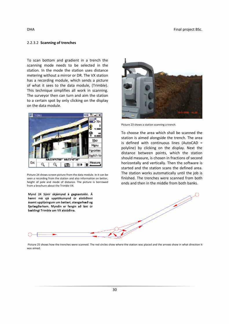
To scan bottom and gradient in a trench the scanning mode needs to be selected in the station. In the mode the station uses distance metering without a mirror or DR. The VX station has a recording module, which sends a picture of what it sees to the data module, (Trimble). This technique simplifies all work in scanning. The surveyor then can turn and aim the station to a certain spot by only clicking on the display on the data module.
Picture 24 shows screen picture from the data module. In it can be seen a recording from the station and also information on better, height of pole and mode of distance. The picture is borrowed from a brochure about the Trimble VX.
Picture 23 shows a station scanning a trench.
To choose the area which shall be scanned the station is aimed alongside the trench. The area is defined with continuous lines (AutoCAD = polyline) by clicking on the display. Next the distance between points, which the station should measure, is chosen in fractions of second horizontally and vertically. Then the software is started and the station scans the defined area. The station works automatically until the job is finished. The trenches were scanned from both ends and then in the middle from both banks.
Picture 25 shows how the trenches were scanned. The red circles show where the station was placed and the arrows show in what direction it was aimed.
DHA Final project BSc.
31
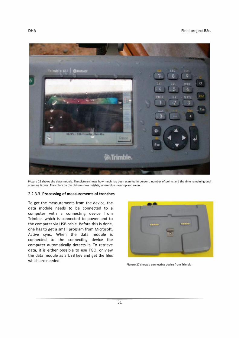
Picture 26 shows the data module. The picture shows how much has been scanned in percent, number of points and the time remaining until scanning is over. The colors on the picture show heights, where blue is on top and so on.
2.2.3.3 Processing of measurements of trenches
To get the measurements from the device, the data module needs to be connected to a computer with a connecting device from Trimble, which is connected to power and to the computer via USB cable. Before this is done, one has to get a small program from Microsoft, Active sync. When the data module is connected to the connecting device the computer automatically detects it. To retrieve data, it is either possible to use TGO, or view the data module as a USB key and get the files which are needed.
Picture 27 shows a connecting device from Trimble

DHA Final project BSc.
32
2.2.4 Working with the outcome
The outcome from the project were processed in Microsoft excel, Real works, Trimble Geomatics office, AutoCAD and SurvCAD. All the calculation of tables was done in Excel. Measuring of trenches were sent electronically to Real works via USB connector on the data module. In Real works the measurements were transformed into points, and those exported to TGO and SurvCAD. In SurvCAD models were made to calculate, filling in of sand and cross-sections drawn of the trenches.
DHA Final project BSc.
33
3 Outcome
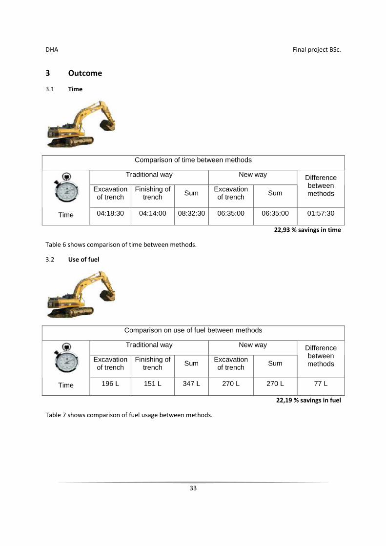
3.1 Time
Comparison of time between methods
Traditional way New way
Excavation of trench
Finishing of trench
Sum Excavation of trench
Sum
Difference between methods
Time 04:18:30 04:14:00 08:32:30 06:35:00 06:35:00 01:57:30
22,93 % savings in time
Table 6 shows comparison of time between methods.
3.2 Use of fuel
Comparison on use of fuel between methods
Traditional way New way
Excavation of trench
Finishing of trench
Sum Excavation of trench
Sum
Difference between methods
Time 196 L 151 L 347 L 270 L 270 L 77 L
22,19 % savings in fuel
Table 7 shows comparison of fuel usage between methods.
DHA Final project BSc.
34
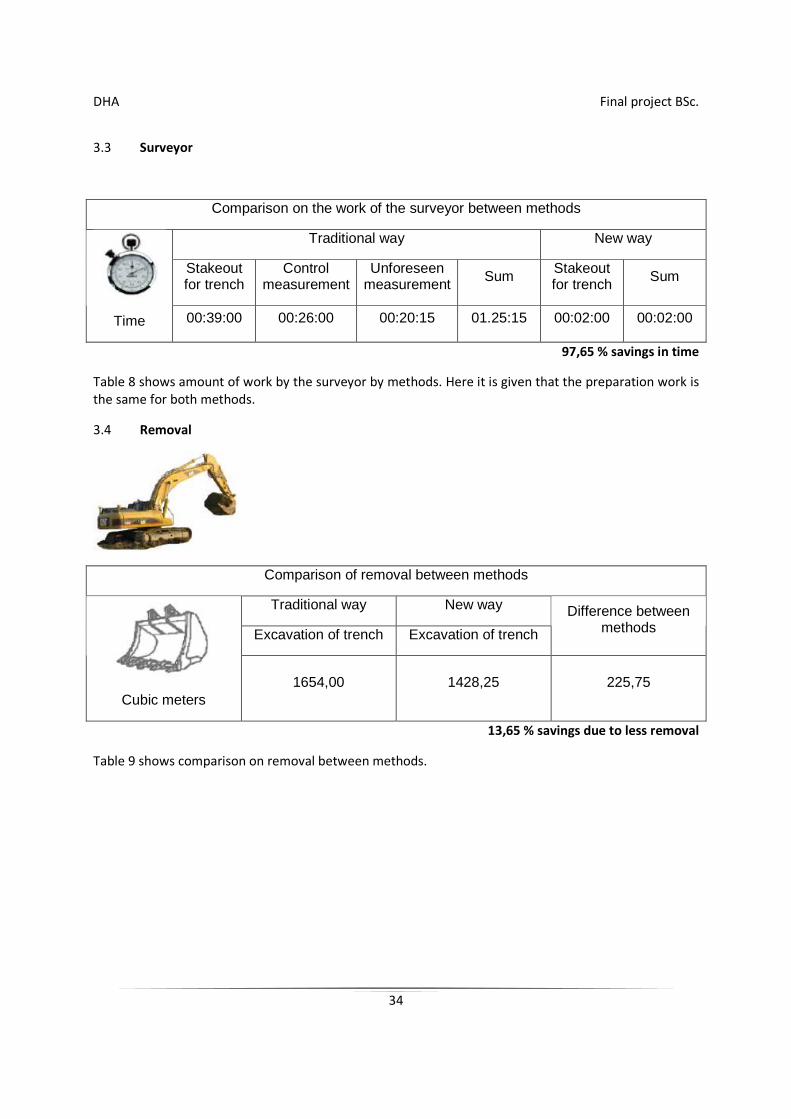
3.3 Surveyor
Comparison on the work of the surveyor between methods
Traditional way New way
Stakeout for trench
Control measurement
Unforeseen measurement Sum Stakeout
for trench Sum
Time 00:39:00 00:26:00 00:20:15 01.25:15 00:02:00 00:02:00
97,65 % savings in time
Table 8 shows amount of work by the surveyor by methods. Here it is given that the preparation work is the same for both methods.
3.4 Removal
Comparison of removal between methods
Traditional way New way
Excavation of trench Excavation of trench
Difference between methods
Cubic meters 1654,00 1428,25 225,75
13,65 % savings due to less removal
Table 9 shows comparison on removal between methods.
DHA Final project BSc.
35
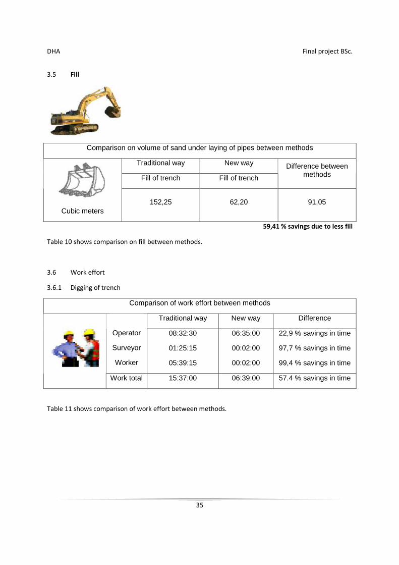
3.5 Fill
Comparison on volume of sand under laying of pipes between methods
Traditional way New way
Fill of trench Fill of trench
Difference between methods
Cubic meters 152,25 62,20 91,05
59,41 % savings due to less fill
Table 10 shows comparison on fill between methods.
3.6 Work effort
3.6.1 Digging of trench
Comparison of work effort between methods
Traditional way New way Difference
Operator
Surveyor
Worker
08:32:30
01:25:15
05:39:15
06:35:00
00:02:00
00:02:00
22,9 % savings in time
97,7 % savings in time
99,4 % savings in time
Work total 15:37:00 06:39:00 57.4 % savings in time
Table 11 shows comparison of work effort between methods.
DHA Final project BSc.
36
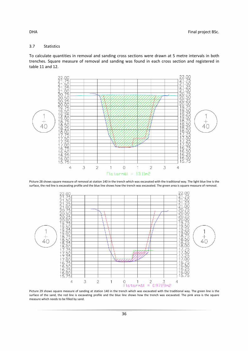
3.7 Statistics
To calculate quantities in removal and sanding cross sections were drawn at 5 metre intervals in both trenches. Square measure of removal and sanding was found in each cross section and registered in table 11 and 12.
Picture 28 shows square measure of removal at station 140 in the trench which was excavated with the traditional way. The light blue line is the surface, the red line is excavating profile and the blue line shows how the trench was excavated. The green area is square measure of removal.
Picture 29 shows square measure of sanding at station 140 in the trench which was excavated with the traditional way. The green line is the surface of the sand, the red line is excavating profile and the blue line shows how the trench was excavated. The pink area is the square measure which needs to be filled by sand.
DHA Final project BSc.
37
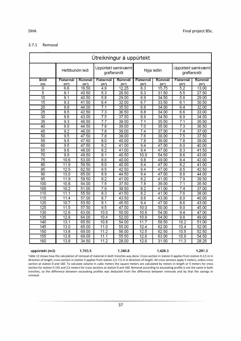
3.7.1 Removal
Table 12 shows how the calculation of removal of material in both trenches was done. Cross-section in station 0 applies from station 0-2,5 m in direction of length, cross-section in station 5 applies from station 2,5-7,5 m in direction of length. All cross sections apply 5 meters, unless cross section at station 0 and 160. To calculate volume in cubic meters the square meters are calculated by meters in length or 5 meters for cross section for station 5-155 and 2,5 meters for cross sections at station 0 and 160. Removal according to excavating profile is not the same in both trenches, so the difference between excavating profiles was deducted from the difference between removals and by that the savings in removal.
DHA Final project BSc.
38
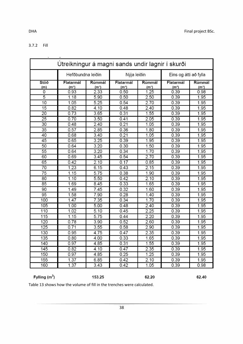
3.7.2 Fill
Table 13 shows how the volume of fill in the trenches were calculated.
DHA Final project BSc.
39
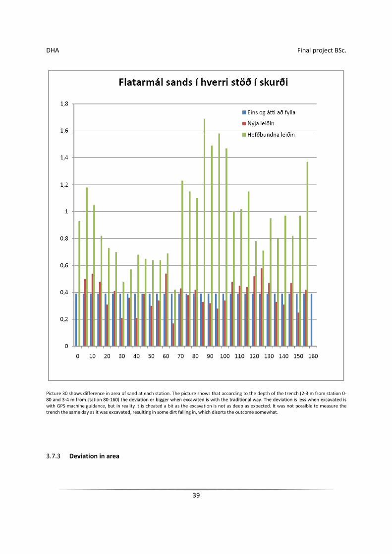
Picture 30 shows difference in area of sand at each station. The picture shows that according to the depth of the trench (2-3 m from station 0-80 and 3-4 m from station 80-160) the deviation er bigger when excavated is with the traditional way. The deviation is less when excavated is with GPS machine guidance, but in reality it is cheated a bit as the excavation is not as deep as expected. It was not possible to measure the trench the same day as it was excavated, resulting in some dirt falling in, which disorts the outcome somewhat.
3.7.3 Deviation in area
DHA Final project BSc.
40
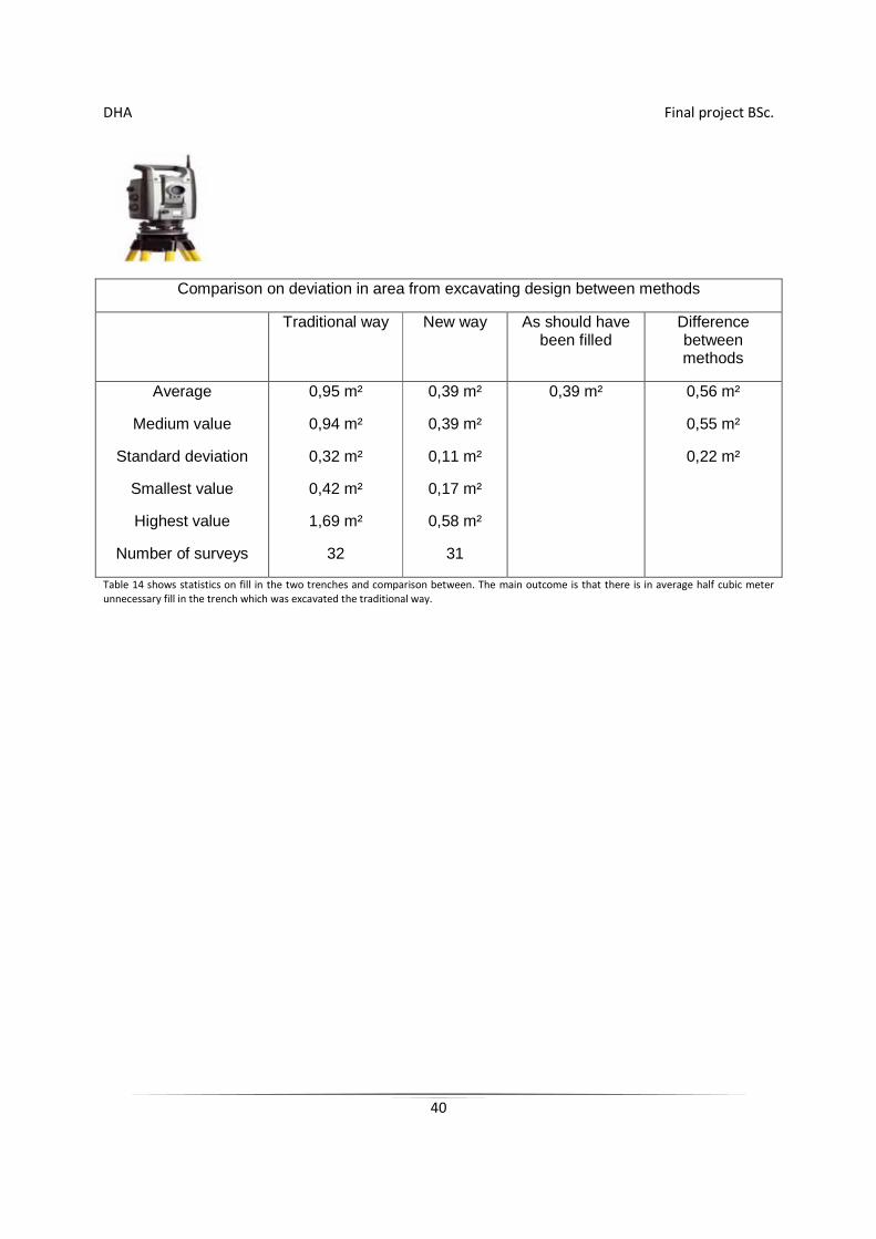
Comparison on deviation in area from excavating design between methods
Traditional way New way As should have been filled
Difference between methods
Average
Medium value
Standard deviation
Smallest value
Highest value
Number of surveys
0,95 m²
0,94 m²
0,32 m²
0,42 m²
1,69 m²
32
0,39 m²
0,39 m²
0,11 m²
0,17 m²
0,58 m²
31
0,39 m² 0,56 m²
0,55 m²
0,22 m²
Table 14 shows statistics on fill in the two trenches and comparison between. The main outcome is that there is in average half cubic meter unnecessary fill in the trench which was excavated the traditional way.
DHA Final project BSc.
41
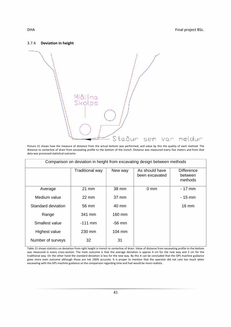
3.7.4 Deviation in height
Picture 31 shows how the measure of distance from the actual bottom was performed, and value by this the quality of each method. The distance to centerline of drain from excavating profile to the bottom of the trench. Distance was measured every five meters and from that data was processed statistical outcome.
Comparison on deviation in height from excavating design between methods
Traditional way New way As should have been excavated
Difference between methods
Average
Medium value
Standard deviation
Range
Smallest value
Highest value
Number of surveys
21 mm
22 mm
56 mm
341 mm
-111 mm
230 mm
32
38 mm
37 mm
40 mm
160 mm
-56 mm
104 mm
31
0 mm - 17 mm
- 15 mm
16 mm
Table 15 shows statistics on deviation from right height in trench to centerline of drain. Value of distance from excavating profile to the bottom was measured in every cross-section. The main outcome is that the average deviation is approx 4 cm for the new way and 2 cm for the traditional way. On the other hand the standard deviation is less for the new way. By this it can be concluded that the GPS machine guidance gives more even outcome although those are not 100% accurate. It is proper to mention that the operator did not care too much when excavating with the GPS machine guidance so the comparison regarding time and fuel would be more realistic.
DHA Final project BSc.
42
4 Discussion and interpretation
The main conclusion in this project is that GPS machine guidance is improving the performance of the belt excavator by minimizing all extra excavation and do prevent doing the same thing twice over. GPS machine guidance saves time which is used for excavation as there is less material excavated for each unit of length. Savings in use of fuel conforms saving in time. Usage of filling material is very low as extra excavation is minimal. Here the time is saved, which would be used to unnecessary fill, and purchase of extra filling material needed. GPS machine guidance does not only increase the performance on the machines it is installed in, but does also have influence on other equipment and manpower. For example there is less driving of trucks as less material equals less driving. Higher accuracy in excavating also reduces the work of the operators as the have to move less material to finish th job. GPS machine guidance also enures more even finish as can be seen on statistics about standard deflection (see table 14).
Deviation in height according to this project is ±40mm, which is in good harmony with approved research. (Retsher & Mitterbauer)
4.1 Advantages and shortcomings of GPS machine guidance
4.1.1 For the operator
Increased comfort, less effort to accomplish same work, no uncertainty on measuring, location or height. Increased discomfort, more responsibility for the operator. Danger of mistakes, as the operator dose not have the same experience as the surveyor in the control and installation of the measuring equipment. Here the operator needs to attend to measuring equipment he himself installs. Possible increase in pay, as the worker is more valuable with this experience.
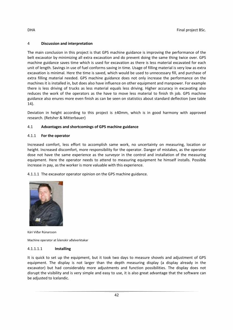
4.1.1.1 The excavator operator opinion on the GPS machine guidance.
Kári Viðar Rúnarsson
Machine operator at Íslenskir aðalverktakar
4.1.1.1.1 Installing
It is quick to set up the equipment, but it took two days to measure shovels and adjustment of GPS equipment. The display is not larger than the depth measuring display (a display already in the excavator) but had considerably more adjustments and function possibilities. The display does not disrupt the visibility and is very simple and easy to use, it is also great advantage that the software can be adjusted to Icelandic.

DHA Final project BSc.
43
4.1.1.1.2 Use
It is great advantage that a profile can be followed on the display and excavate exactly by it, and the it is possible to get several views of the operation. If the condition for measure worsens the software lets you know and stops you. It is possible to choose speed possibilities on the display as you wish, for example change of bucket, choose right or left end of bucket for guidance and so on. It is a great disadvantage that there are not possibilities to have surface ore bottom measurements as a selection in the software and this needs to be changed. It did disturb me in the beginning when I was excavating in cross section and the left end of bucket did enter the slope then the equipment did ask for the left end to be lifted some x much although the right end had asked to be lowered x much. Furthermore I did get mixed up when the slope between portholes did steadily change in the bend and the display was constantly changing the slope, which is very natural when one had figured this out. I would not have believed how simple the equipment is in use before I did start using it and I am sure that there are few who can not master this very quickly.
4.1.2 For the surveyor
Higher optimization in work as the work in the field is less, mainly because the rearrangement of stakes is eliminated. Arrangement of stakes for works is diminished but measurement on land and rocks should be the same as it is customary to perform surface measuring before project start to keep record of volume statistics. Of course it is possible to have heavy equipment to measure the surface, but it would never be cost effective unless in very special circumstances, for example far away in the countryside where it is a long journey for the surveyor. The time which would be used for measuring in the field can be used in preparation of data of other projects, calculation of volume and supervision on the site.
Extended teaching of software, here the surveyor needs to learn new software, unless it is the same as he is using today. Possibly the surveyor needs to teach the operator proper use of the device.
4.1.3 For the company
Higher optimization as a belt excavator with GPS machine guidance is of better use as the machine is self-contained and can work independent of the surveyor, who is not always available. Furthermore the the machine is better utilized as the work is more systematic. Cost because of purchase of material is much lower.
Driving of trucks diminishes as less material is driven from the site and less fill as all unnecessary excavation is largely diminished. Extra cost because of wages of operator as he gets more valuable due to extended work knowledge. On the other hand it is easier to get younger men to work with the machines ef those are with machine guidance.
4.2 Suitability of GPS machine guidance
4.2.1 GENERAL
GPS machine guidance are suited everywhere, if nothing stands in the way of sight of satellite receiver and satellite. For example not in tunnels, in forests, by high rise buildings and beneath steep hills. Most new GPS machine guidance support Global Navigational Satellite System
(GNSS)(Trimble, 2006) which is a satellite system based on á GPS and GLObal'naya NAvigatsionnaya Sputnikovaya Sistema (GLONASS)(Polischuk &
DHA Final project BSc.
44
Revnivykh, 2004). The GNSS system ensures extra stability in height, localization and increases possibility on the right orientation of satellites in receiving in difficult situations.
4.2.2 At different jobs
GPS machine guidance is well utilized in road construction street building and land formation where constant measuring is needed. Machine guidance offers measurement with difficult situations, as in deep trenches, excavation of harbors or where the surveyor can not operate because of safety.
Finishing of rocks in seawalls is without doubt feasible. In simple projects which are calling for little surveying it is more difficult to justify use of GPS machine guidance because of starting cost.
4.3 Notes on the assignment
4.3.1 Severe Applications
Earth was frozen when the project was started, and it did go 30 - 40 cm below the surface. As the job went on the site area it began to thaw and the area became muddy which did influence the outcome. Biggest problem was abnormal collapse in the trench which was excavated with the new method. The operator did totally follow the excavation profile which was simply too steep for the earth and the organic soil on top of the trench. In the other trench there was similar collapse but there one day was between it was excavated and until it was fixed. Therefore the operator could fix what had fallen down in the meantime.
DHA Final project BSc.
45
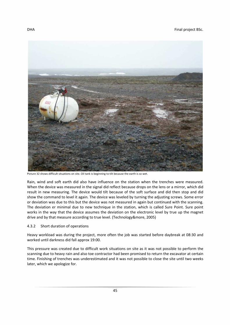
Picture 32 shows difficult situations on site. Oil tank is beginning to tilt because the earth is so wet.
Rain, wind and soft earth did also have influence on the station when the trenches were measured. When the device was measured in the signal did reflect because drops on the lens or a mirror, which did result in new measuring. The device would tilt because of the soft surface and did then stop and did show the command to level it again. The device was leveled by turning the adjusting screws. Some error or deviation was due to this but the device was not measured in again but continued with the scanning. The deviation er minimal due to new technique in the station, which is called Sure Point. Sure point works in the way that the device assumes the deviation on the electronic level by true up the magnet drive and by that measure according to true level. (Technology&more, 2005)
4.3.2 Short duration of operations
Heavy workload was during the project, more often the job was started before daybreak at 08:30 and worked until darkness did fall approx 19:00.
This pressure was created due to difficult work situations on site as it was not possible to perform the scanning due to heavy rain and also toe contractor had been promised to return the excavator at certain time. Finishing of trenches was underestimated and it was not possible to close the site until two weeks later, which we apologize for.
DHA Final project BSc.
46
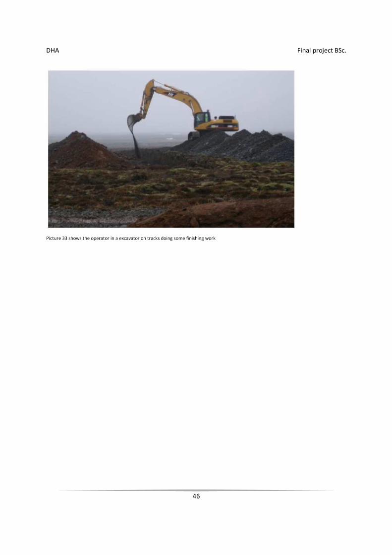
Picture 33 shows the operator in a excavator on tracks doing some finishing work
DHA Final project BSc.
47
5 Summary
The main conclusion in this project is that GPS machine guidance is improving the performance of the belt excavator by minimizing all extra excavation and do prevent doing the same thing twice over. By this considerable time and fuel is saved. When unnecessary excavation is minimal much work by filling is saved and cots because of purchase of sand is 59% less. GPS machine guidance ensures less deviation in height with accuracy ±4cm. Construction equipment with GPS machine guidance are better utilized ad the as the machine is self-contained and can work independent of the surveyor, who is not always available. Driving of trucks diminishes when GPS machine guidance is used, as less material is driven from the site and less fill as all unnecessary excavation is largely diminished. The equipment is easy to use and user friendly according to the operator of the excavator, who was using it for the first time.
The findings in this project confirm that GPS machine guidance in a excavator can optimize excavation work by increasing speed, lower cost and return satisfactory accuracy in the project.
DHA Final project BSc.
48
6 References
Björnsson.Þór, J. (2006). Ný kynslóð landmælingartækja Hnit hf. (New generation of surveying equipment, Hnit hf)
Böðvarsson, Á. (1996). Landmælingar og kortagerð Dana á Íslandi. (Danish land surveying and mapping in Iceland. Reykjavík: Landmælingar Íslands. (National Land Survey of Iceland)
Caterpillar. (2006A). Notkunar- og viðhaldshandbók AccuGrade GPS (CD700) [Operation and Maintenance Manual AccuGrade GPS (CD700)]
Caterpillar.
Caterpillar. (2006B). Road construction production study.
Jóhannesson, M. (1999). Reglugerð um viðmiðun ÍSN93, grunnstöðvanet og mælistöðvar til notkunar við landmælingar og kortagerð (Directive on guidelines ÍSN93, basenet og measuring points for use in surveying and mapping).
Umhverfisráðuneytið (The Icelandic Ministry for the Environment).
Magnússon.Þór, I., Þorbergsson, G., & Björnsson.Þór, J. (1997). GPS-MÆLINGAR Í GRUNNSTÖÐVANETI 1993 og ný viðmiðun ISN93 við landmælingar á Íslandi Landmælingar Íslands mælingadeild, (GPS-MEASUREMENTS IN THE BASE NETWORK 1993 and new reference ISN93 in surveying in Iceland. National Land Survey of Iceland, surveying dept.)
National Imagery and Mapping Agency. (2000).
DEPARTMENT OF DEFENSE WORLD GEODETIC SYSTEM 1984
its definition and relationships with local geodetic systems National Imagery and Mapping Agency.
Orkuveita Reykjavíkur (Reykjavik Energy). (2007). Standard profiles of Reykjavik Energy. Orkuveita Reykjavíkur (Reykjavik Energy).
Polischuk, G. M., & Revnivykh, S. G. (2004). Status and development of GLONASS. Acta Astronautica, 54(11-12), 949-955.
Retsher, G., & Mitterbauer, U. Kinematic trajectory determination for constrution machines.
Administration of Occupational Safety and Health in Iceland (1990). Safety demands in excavation No 2) Administration of Occupational Safety and Health in Iceland
Technology&more. (2005). Trimble´s magdrive servo technology.(3)
Trimble. Trimble spatial imaging: Bringing geospatial information down to earth.
Trimble. (2006). Defining the future of satellite surveying with Trimble R-track technology
Wolf.R, P., & Ghilani.D, C. (2006). Elementary surveying an introduction to geomatics. Upper Saddle River,New Jersey: Pearson Prentice Hall.
DHA Final project BSc.
49
Appendixes
1 Surveying
1.2 History of surveying
Oldest source of information available today which can be directly linked to surveying is from Egypt approx year 1400 B.C. Herodotus recorded that Sesostris should divide then land of Egypt into squares to tax landowners. The river Nile used to overflow its banks and one of the tasks of those ancient surveyors was to reclaim the boundaries. The surveyors were called rope pullers as they did use a rope in their work with markings on certain lengths
Ancient Greeks did combine the science to surveying and called it geometry. The Greeks were the first to make special equipment for surveying (The dioptra) about 120 B.C. The Romans did develop their own equipment and technique which did make the standard for many years to come. Little progress was in the middle ages, the Arabs did maintain the little which was there. In the eighteenth and nineteenth century nineteenth surveying developed due to ever-growing need for maps and location of international boundaries. When price of land and needs for better roads was actual, this did set ground for surveying. Continued development and construction has made surveying a necessary part in our daily life. Besides to serve the needs of civilians necessary technique has proven itself as a useful tool in defense. Wars during the ages did influence the increase of technical development in surveying due to increased demand for accuracy. Surveying did supply knowledge and did benefit much from the space journey projects of the US about 1970. A new system was introduced, the GPS satellite system.(Wolf.R & Ghilani.D, 2006)
1.3 History of surveying in Iceland
About 1874 the demands for new land surveying became more visible. One of the largest motivations was the exploitation the foreigners did at the Icelandic coastline and the insecurity in seafaring. The Danish war ministry did issue a directive in the year 1900 that the surveying department of the military staff should send a expedition to Iceland that year to measure a baseline, which would be sufficient for the planned hydrography around Reykjanes. Furthermore the geographical position, latitude, longitude and azimuth should be measured by astronomy. In the year 1939 the surveying and mapping of the country was finished with many delays due to the first world war and various difficulties. (Böðvarsson, 1996)
1.4 Trigonometry
Before the time of electronic length surveying, trigonometry was mainly used for plan surveying, specially for spacious areas.
It was more easy to calculate a angle than distance, specially where long lines did cross uneven land and forests. By building towers and heighten the surveyor with instrument, surveying was easy. Trigonometry covers a number of observations which help out to find errors and wrong information when surveying. This results in high accuracy in trigonometry.
DHA Final project BSc.
50
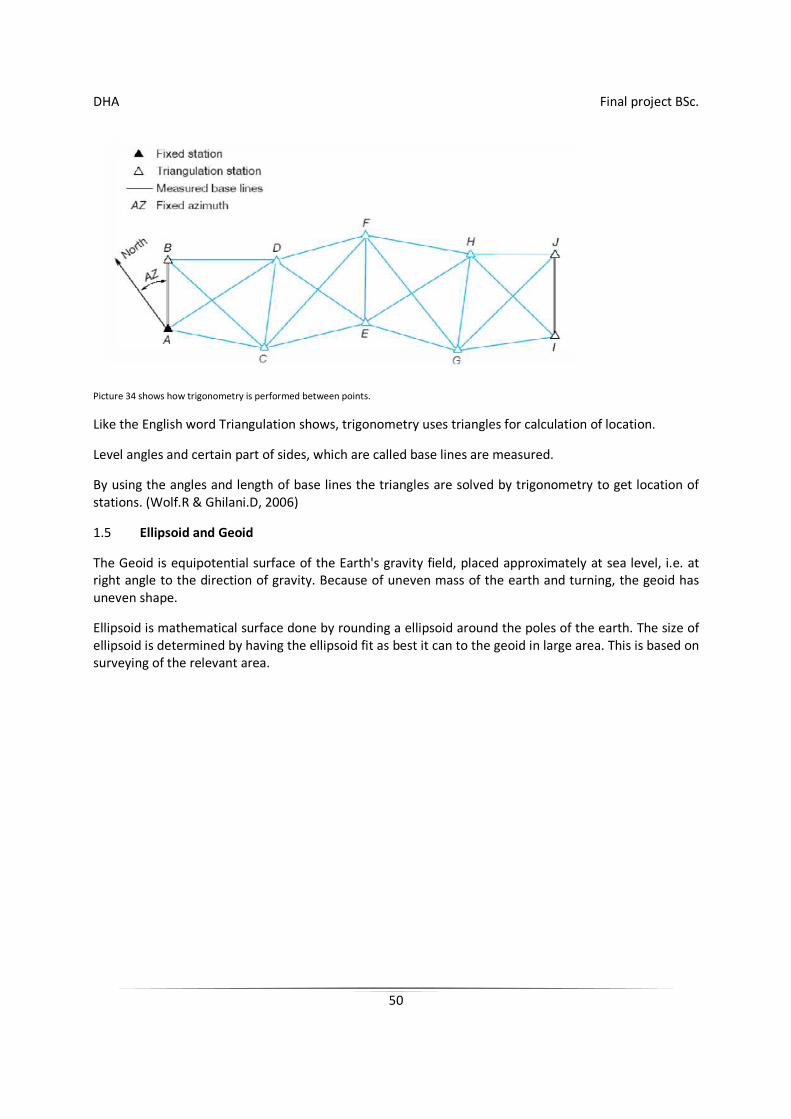
Picture 34 shows how trigonometry is performed between points.
Like the English word Triangulation shows, trigonometry uses triangles for calculation of location.
Level angles and certain part of sides, which are called base lines are measured.
By using the angles and length of base lines the triangles are solved by trigonometry to get location of stations. (Wolf.R & Ghilani.D, 2006)
1.5 Ellipsoid and Geoid
The Geoid is equipotential surface of the Earth's gravity field, placed approximately at sea level, i.e. at right angle to the direction of gravity. Because of uneven mass of the earth and turning, the geoid has uneven shape.
Ellipsoid is mathematical surface done by rounding a ellipsoid around the poles of the earth. The size of ellipsoid is determined by having the ellipsoid fit as best it can to the geoid in large area. This is based on surveying of the relevant area.
DHA Final project BSc.
51
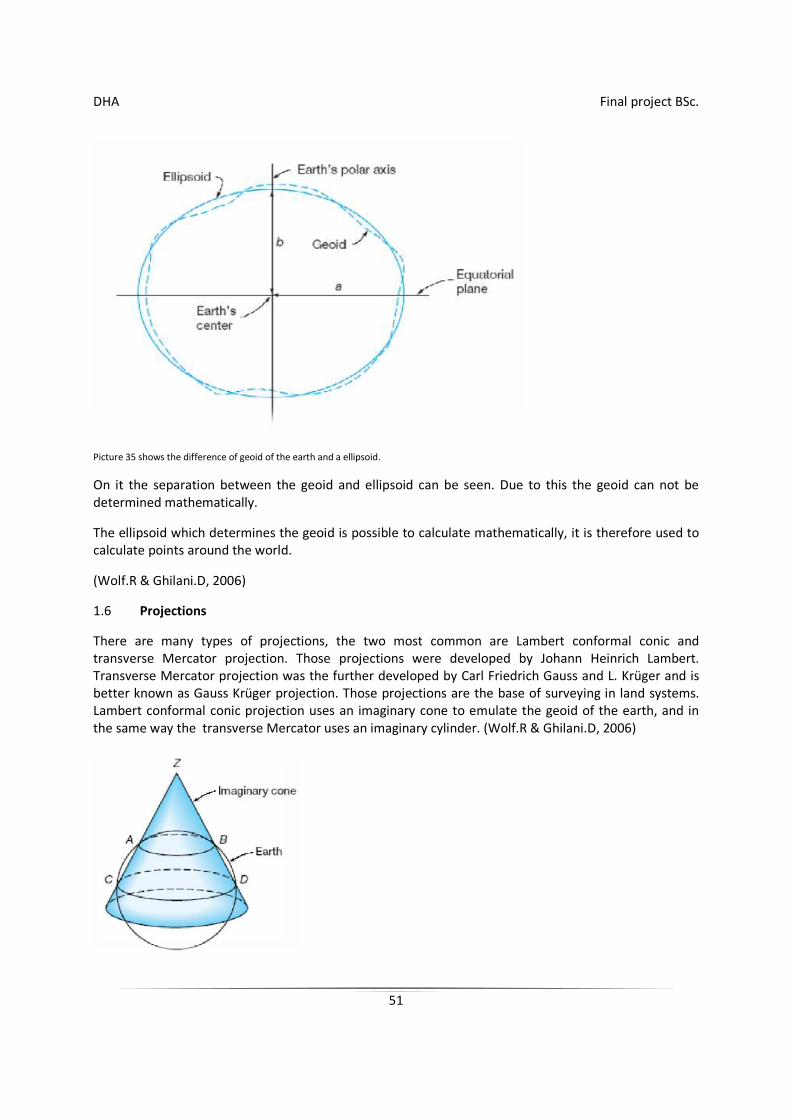
Picture 35 shows the difference of geoid of the earth and a ellipsoid.
On it the separation between the geoid and ellipsoid can be seen. Due to this the geoid can not be determined mathematically.
The ellipsoid which determines the geoid is possible to calculate mathematically, it is therefore used to calculate points around the world.
(Wolf.R & Ghilani.D, 2006)
1.6 Projections
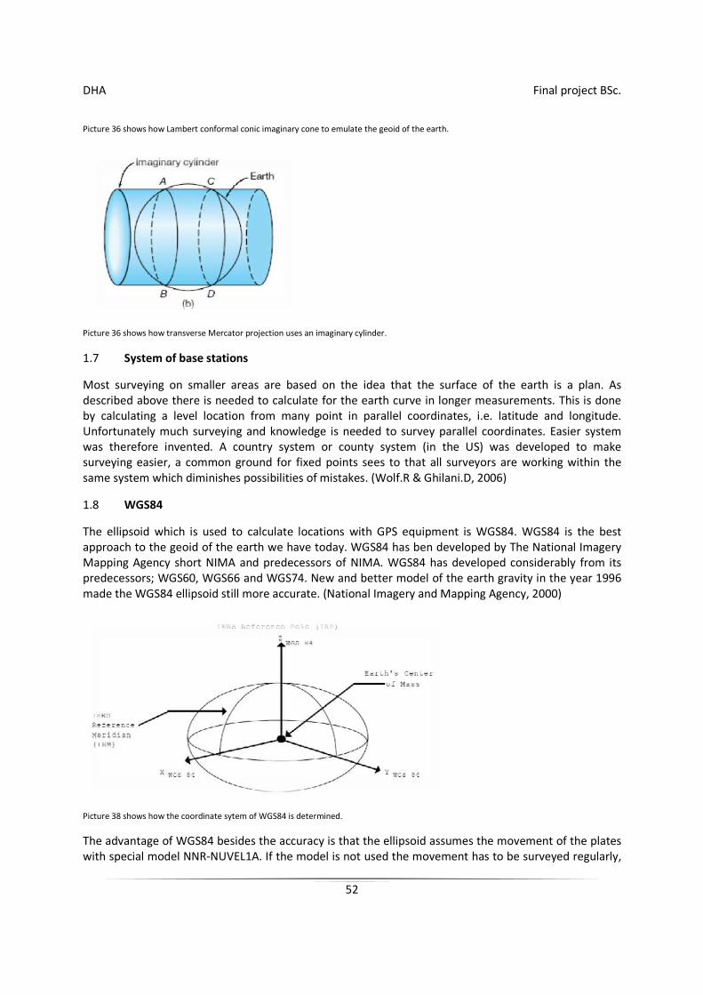
There are many types of projections, the two most common are Lambert conformal conic and transverse Mercator projection. Those projections were developed by Johann Heinrich Lambert. Transverse Mercator projection was the further developed by Carl Friedrich Gauss and L. Krüger and is better known as Gauss Krüger projection. Those projections are the base of surveying in land systems. Lambert conformal conic projection uses an imaginary cone to emulate the geoid of the earth, and in the same way the transverse Mercator uses an imaginary cylinder. (Wolf.R & Ghilani.D, 2006)
DHA Final project BSc.
52
Picture 36 shows how Lambert conformal conic imaginary cone to emulate the geoid of the earth.
Picture 36 shows how transverse Mercator projection uses an imaginary cylinder.
1.7 System of base stations
Most surveying on smaller areas are based on the idea that the surface of the earth is a plan. As described above there is needed to calculate for the earth curve in longer measurements. This is done by calculating a level location from many point in parallel coordinates, i.e. latitude and longitude. Unfortunately much surveying and knowledge is needed to survey parallel coordinates. Easier system was therefore invented. A country system or county system (in the US) was developed to make surveying easier, a common ground for fixed points sees to that all surveyors are working within the same system which diminishes possibilities of mistakes. (Wolf.R & Ghilani.D, 2006)
1.8 WGS84
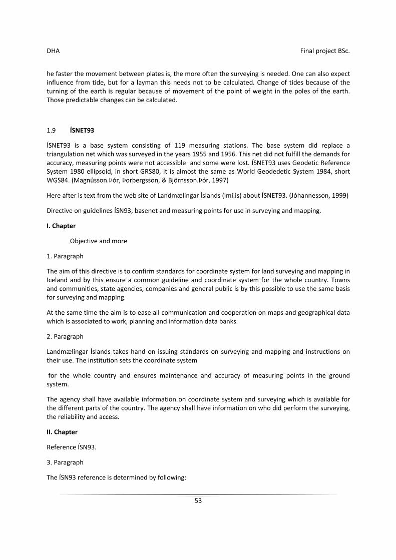
The ellipsoid which is used to calculate locations with GPS equipment is WGS84. WGS84 is the best approach to the geoid of the earth we have today. WGS84 has ben developed by The National Imagery Mapping Agency short NIMA and predecessors of NIMA. WGS84 has developed considerably from its predecessors; WGS60, WGS66 and WGS74. New and better model of the earth gravity in the year 1996 made the WGS84 ellipsoid still more accurate. (National Imagery and Mapping Agency, 2000)
Picture 38 shows how the coordinate sytem of WGS84 is determined.
The advantage of WGS84 besides the accuracy is that the ellipsoid assumes the movement of the plates with special model NNR-NUVEL1A. If the model is not used the movement has to be surveyed regularly,
DHA Final project BSc.
53
he faster the movement between plates is, the more often the surveying is needed. One can also expect influence from tide, but for a layman this needs not to be calculated. Change of tides because of the turning of the earth is regular because of movement of the point of weight in the poles of the earth. Those predictable changes can be calculated.
1.9 ÍSNET93
ÍSNET93 is a base system consisting of 119 measuring stations. The base system did replace a triangulation net which was surveyed in the years 1955 and 1956. This net did not fulfill the demands for accuracy, measuring points were not accessible and some were lost. ÍSNET93 uses Geodetic Reference System 1980 ellipsoid, in short GRS80, it is almost the same as World Geodedetic System 1984, short WGS84. (Magnússon.Þór, Þorbergsson, & Björnsson.Þór, 1997)
Here after is text from the web site of Landmælingar Íslands (lmi.is) about ÍSNET93. (Jóhannesson, 1999)
Directive on guidelines ÍSN93, basenet and measuring points for use in surveying and mapping.
I. Chapter
Objective and more
1. Paragraph
The aim of this directive is to confirm standards for coordinate system for land surveying and mapping in Iceland and by this ensure a common guideline and coordinate system for the whole country. Towns and communities, state agencies, companies and general public is by this possible to use the same basis for surveying and mapping.
At the same time the aim is to ease all communication and cooperation on maps and geographical data which is associated to work, planning and information data banks.
2. Paragraph
Landmælingar Íslands takes hand on issuing standards on surveying and mapping and instructions on their use. The institution sets the coordinate system
for the whole country and ensures maintenance and accuracy of measuring points in the ground system.
The agency shall have available information on coordinate system and surveying which is available for the different parts of the country. The agency shall have information on who did perform the surveying, the reliability and access.
II. Chapter
Reference ÍSN93.
3. Paragraph
The ÍSN93 reference is determined by following:
DHA Final project BSc.
54
1. Earth central system ITRF93.6 (International Terrestrial Reference Frame
1993.6). The Z-axis of the system coincides with the turning axis of the earth, but X- and Y-axis the equator. X-axis is in the Greenwich meridian, but the Y-axis at right angle to the X-axis to the east.
2. Ellipsoid GRS-80 (Geodetic Reference System 1980).
The parameters of the ellipsoid is following:
a)half the major axis a = 6 378 137 m.
b)the weight factor of the earth compared to the center of the earth GM = 3986005•108 •m3 •s-2
c)analytical coefficeient of the earth J2 = 108263•10-8
d)medium angle speed of the earth = 7292115•10-11•rad•s-1
Therefore the polar area of the ellipsoid f = 1/298,257222101.
3. Outcome of GPS-measurement 1993 of basis net system of 119 measuring points (ÍSNET93), sbr. paragraph 5.
4. Paragraph
The countries coordinate system, acc. paragraph 9., has the reference ÍSN93, acc. paragraph 3., and takes over older references:
Reykjavík 1900 and Hjörsey 1955.
III. Chapter
Base coordinate system.
5. Paragraph
Base coordinate system consists of 119 measuring points, which were measured 1993 in the land surveying project ÍSNET93, according to appendix 1 and 2.
6. Paragraph
Landmælingar Íslands shall maintain and supervise the Base coordinate system.
The institution shall resurvey the points as needed.
If a change of land or part of land has taken place, shall that part of the coordinate system which the change applies be measured again with appropriate surveying methods and equipment as son as possible.
7. Paragraph
The whole base coordinate system shall be measured in whole not less than every 10th year.
DHA Final project BSc.
55
8. Paragraph
If a measuring point in the base coordinate system needs moving an remarking it shall be done under the supervision of Landmælingar Íslands.
9. Paragraph
In surveying and mapping shall use coordinates on true right Lambert conformal conic projection, where the scale is one on the parallel of latitude 64°15’ and 65°45’ north. The axis of the coordinate system are called east axis and north axis. The north axis is to the north on meridian 19° west, but the east axis true right on the north axis to the east at 65° north. The crossing point of the axis has the coordinates = 500.000,000 meters and east = 500.000,000 meters. The direction is measured and calculated clockwise from north to the east.
IV. Chapter
Measuring points connected to the base coordinate system
10. Paragraph
Measuring points connected to the base coordinate system shall be permanent, a pillar or screw bolt. Those shall be clearly marked with number, year and initials of the institute or firm which has performed the work according to paragraph 14.
11. Paragraph
Surveying of new and older points from base net shall not have more standard deviation than two centimeters to or from (+/- 2 cm) in placement and three centimeters to or from (+/- 3 cm) in height.
12. Paragraph
Measuring point shall be remarked when older marking has been moved, disrupted or lost. Remarking can only be done with the approval of the institute or firm, which originally did mark the measuring point.
Landmælingar Íslands shall be notified about the remarking and delivered all the concerning data for registration (surveying, processing and description).
13. Paragraph
If a measuring point is remarked it shall receive a new number according to paragraph 14 in coordinated numbering system of Landmælingar Íslands.
14. Paragraph
Number of measuring station can be up to eight numbers.
The first two letters shall be identifying the party which did set up the station and then up to six digit number. latter part of the number can be up to eight digits if special circumstances call for it. Landmælingar Íslands shall be consulted regarding use of identifying numbers.
15. Paragraph
DHA Final project BSc.
56
A description shall be made of the measuring station when it is set up. It shall be clear and descriptive so it is easy to find the station and value its usefulness. The description shall be maintained and changed as needed, such as due to change in route to measuring station or its next vicinity.
V. Chapter
Different clauses
16. Paragraph
Landmælingar Íslands shall provide more detailed information and instructions about the older system, base net, reference ÍSN93,
station descriptions, so about other issues which this regulation covers.
17. Paragraph
This regulation is made according to authority in 12. paragraph in laws about surveying and mapping no. 95/1997 according to law no. 132/1998, and is now in effect.
Umhverfisráðuneytinu (Ministry of environment), December 20 th 1999.
(Siv Friðleifsdóttir)
DHA Final project BSc.
57
2 Measuring equipment
Following texts are borrowed from Jón Þór Björnsson, surveying engineer at engineering firm Hnit Hf. (Björnsson.Þór,J. 2006)
2.1 Overview
In the last 10-15 years there has almost been a revolution in equipment for surveying. This applies for most surveying equipment, but those are mainly:
1. laser-equipment for length-, direction and surface surveying in horizontal, vertical and sloping plane.
2. Base station with remote control, i.e. one man station, where outcome of the survey (coordinate and deviation of structure) are immediately available in the field.
3. immediately, which is the largest revolution in land surveying technique for location, which is based on receiving high frequency signals from satellites in 20,200 km height above the earth.
Hereafter it will be explained in core the progress and changes which have taken place, comparison will also be made between older and new technique, and comments about where and when this new technique is best used.
It will be tried, as best as possible, to avoid too technical explanations.
1. Laser-equipment
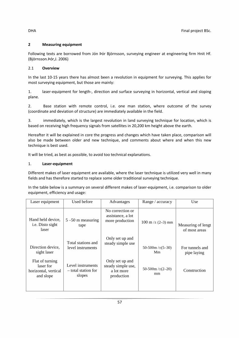
Different makes of laser equipment are available, where the laser technique is utilized very well in many fields and has therefore started to replace some older traditional surveying technique.
In the table below is a summary on several different makes of laser-equipment, i.e. comparison to older equipment, efficiency and usage:
Laser equipment Used before Advantages Range / accuracy Use
Hand held device, i.e. Disto sight
laser
Direction device, sight laser
Flat of turning laser for
horizontal, vertical and slope
5 –50 m measuring tape
Total stations and level instruments
Level instruments – total station for
slopes
No correction or assistance, a lot more production
Only set up and steady simple use
Only set up and steady simple use,
a lot more production
100 m /± (2–3) mm
50-500m /±(5–30) Mm
50-500m /±(2–20) mm
Measuring of lengt of most areas
For tunnels and pipe laying
Construction
DHA Final project BSc.
58
2. Base station with remote control (single user station)
In Iceland there are already several single user stations in use, i.e. one person can perform all the surveying with such stations, but this equipment is from various manufactures, such as Leica or Trimble.
The station sends a infrared beam, when length measuring towards the mirror, which reflects the beam from the mirror back to the station, which senses the reflection and controls the telescope automatically towards the mirror and then follows the movement of the mirror on the weighted stake. Due to this the Leica mirror is very well suited, as it is not needed to control every time that it faces the measuring device, but it is feasible to adjust the stake so high that it dos not disrupt the transmission of the infra red beam from the station.
The range for single user stations is between 400-800 meters, which is mainly subject to type of mirror and the transmission power of the transmitter.
Most of the stations are equipped with vertical laser to simplify the setup on fixed points.
The basic adjustment of the device is always performed before surveying, but those are mainly: choice of prisma, mode of surveying (speed of surveying), various corrections due to heat, air pressure, projection, error in scale and other, and also the fixed marks register needs to be chosen, surveying register, mode of display and registering.
It is possible to adjust the device to own needs, i.e. regarding adjustment of brightness, measuring, calculation and explanation of measuring point (code. Also it is possible to choose what data shall be registered on the data cards, i.e. number of point, calculated coordinate, explanations, design coordinates and deviations.
The station is equipped in the way that it corrects automatically the survey against various errors, which can occur due to external effects, only to certain limit, but then there is a warning message on the display and then necessary corrections needs to be done to the device each time, before surveying can continue.
The direction accuracy of the equipment is divided into groups, which is approx ±1,5" to ±5" and the
accuracy in length in quality surveying ±(2mm+2mm/km) and if remote is used
±(3mm+3mm/km).
The range for length surveying with one round mirror is approx 3000 meters, but if the remote is connected to the station, then the range for a round mirror is 800-1000m and 400-600m with 360° mirror.
The advantage of one person stations is without doubt large in comparison to older stations, specially regarding technique, production and not to the least efficiency, where only one person can perform all the surveying and the security of the surveying is more ensured, where the surveyor himself stakes out the measuring points in the fields.
This surveying equipment is very well suited in well-defined operation areas, regarding the range of the equipment and they are also well suited indoors and in closed building sites.
DHA Final project BSc.
59
3. GPS - satellite surveying
This is the biggest revolution in land surveying technique for localization, but this is based on receiving high frequency signals from 24 satellites (+ spare satellites), which are roaming on predetermined orbit 20.200 km above the earth. The circulation time of the satellites is 12 hours.
Raunvísindastofnun (Science Institute of the University of Iceland) will most likely have received the first Trimble GPS-surveying equipment in this country, but the engineering firm Hnit h/f did come by the first Leica GPS-300-devices with real time processing 1996.
Today there are many firms who use GPS-real time land surveying devices from Leica and Trimble and it is clear that users will increase over the next years.
In GPS-land surveying there are used at least two GPS-devices, where so called differential technique is used, which means that a baseline from known measuring station, main station (Reference), to unknown station, (Rover). In further calculation are used two basic methods:
a) Post Processing: GPS-data from satellites is saved and calculation later done with software.
b) Real Time: Processing of GPS-data is performed immediately in the field, which gives constant true positioning.
Baseline accuracy a) between two GPS-stations is ±(5mm + 1ppm), but in b) ±(10-30mm +
2ppm)
DHA Final project BSc.
60
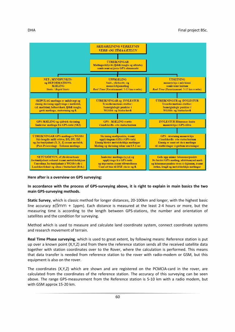
Here after is a overview on GPS surveying:
In accordance with the process of GPS-surveying above, it is right to explain in main basics the two main GPS-surveying methods.
Static Survey, which is classic method for longer distances, 20-100km and longer, with the highest basic
line accuracy ±(5mm + 1ppm). Each distance is measured at the least 2-4 hours or more, but the measuring time is according to the length between GPS-stations, the number and orientation of satellites and the condition for surveying.
Method which is used to measure and calculate land coordinate system, connect coordinate systems and research movement of terrain.
Real Time Phase surveying, which is used to great extent, by following means: Reference station is put up over a known point (X,Y,Z) and from there the reference station sends all the received satellite data together with station coordinates over to the Rover, where the calculation is performed. This means that data transfer is needed from reference station to the rover with radio-modem or GSM, but this equipment is also on the rover.
The coordinates (X,Y,Z) which are shown and are registered on the PCMCIA-card in the rover, are calculated from the coordinates of the reference station. The accuracy of this surveying can be seen above. The range GPS-measurement from the Reference station is 5-10 km with a radio modem, but with GSM approx 15-20 km.
DHA Final project BSc.
61
It is clear that that real time surveying is well suited for large open building sites, i.e. power plant sites, in road building, positioning of various buildings, profile- and surface surveying and more.
It shall be pointed out that average error in height (Z) can be up to double larger than in plane (X,Y) and therefore it is more risky to use real time surveying
in final stakeout or final appraisal of the height of roads, unless with very good measuring conditions.
GPS-surveying has several advantages in addition to traditional stations or single user stations such as:
Are independent of status of light and weather (not wind) i.e. it is possible to survey in rain, fog and at night.
Line of sight between measuring stations is unnecessary in static surveying, and also to certain extent in real time surveying (specially GSM), measuring is automatic or semi-automatic, but there are at least 4 satellites needed and good GPS-conditions.
Performance and efficiency considerably more in most cases.
Possibility to establish a system of ground stations, as is planned in Germany, but the the used only needs one GPS-station, i.e. rover, but such a system country-wide is very costly, as there is need to ensure both quality and safety of the system, as well as operation and maintenance.
The limitations of GPS-measuring in comparison to traditional stations or single user stations are:
GPS-measuring is slow and does not suit in the neighborhood of large structures, in narrow streets and where a line of sight is possible between rovers and satellites.
It is difficult to use GPS on steep hillsides, in narrow fjords or where trees block the satellites.
By this information, which has been shown here, it is evident that much progress has been over the last years in the technique and equipment for surveying, it is clear that great changes can be expected, in relation to guidance of large construction machinery.
There are already productive kerbstone laying machines which are controlled by a station and 360° mirror, similar technique is used for laying of asphalt or concrete. Already large construction machines, i.e. bulldozers are fitted with GPS-equipment which shows any given time the cross-section of structure on a computer display and informs when design has been excavated or filled in.
DHA Final project BSc.
62
3 Machine guidance
3.1 History of machine guidance
In the mid-sixties Robert Studebaker did invent the turning laser or prism, which could send a light which did compose a plan. Four years later the first machine guidance system which was controlled by a laser beam was invented. In the beginning the machine guidance were not much used due to high cost of assessories, such as batteries and control equipment. In thirty years the price came down 75% which resulted in contractors starting to use the equipment. Just before the turn of the century there was a high leap in sales of machine guidance when the first Universal Total stations and later the GPS machine guidance were introduced.
3.2 Machine guidance in general
Machine guidance is a device control where the hydraulic system of a machine is connected to a sensor which moves a blade on bulldozer or a road planer in certain height.
Machine guidance is divided into three types. There is laser controlled machine guidance, machine guidance controlled by a station and GPS machine guidance. Like the wording states the machine guidance is driven by signals from satellites, control station and newest from a GPS satellites and correction from a control station. Machine guidance is the divided into two groups, on one hand automatic, where the guidance controls a blade on road planer or a bulldozer according to design height each time. There the operator drives the bulldozer or the road planer on reasonable speed and the blade lifts or lowers totally by itself.On the other hand tere are non-automatic machine guidance, those are for example in excavators, but there the operator works according to information on a data display in the excavator.In this project there will bee looked at GPS controlled machine guidance in a excavator on tracks.
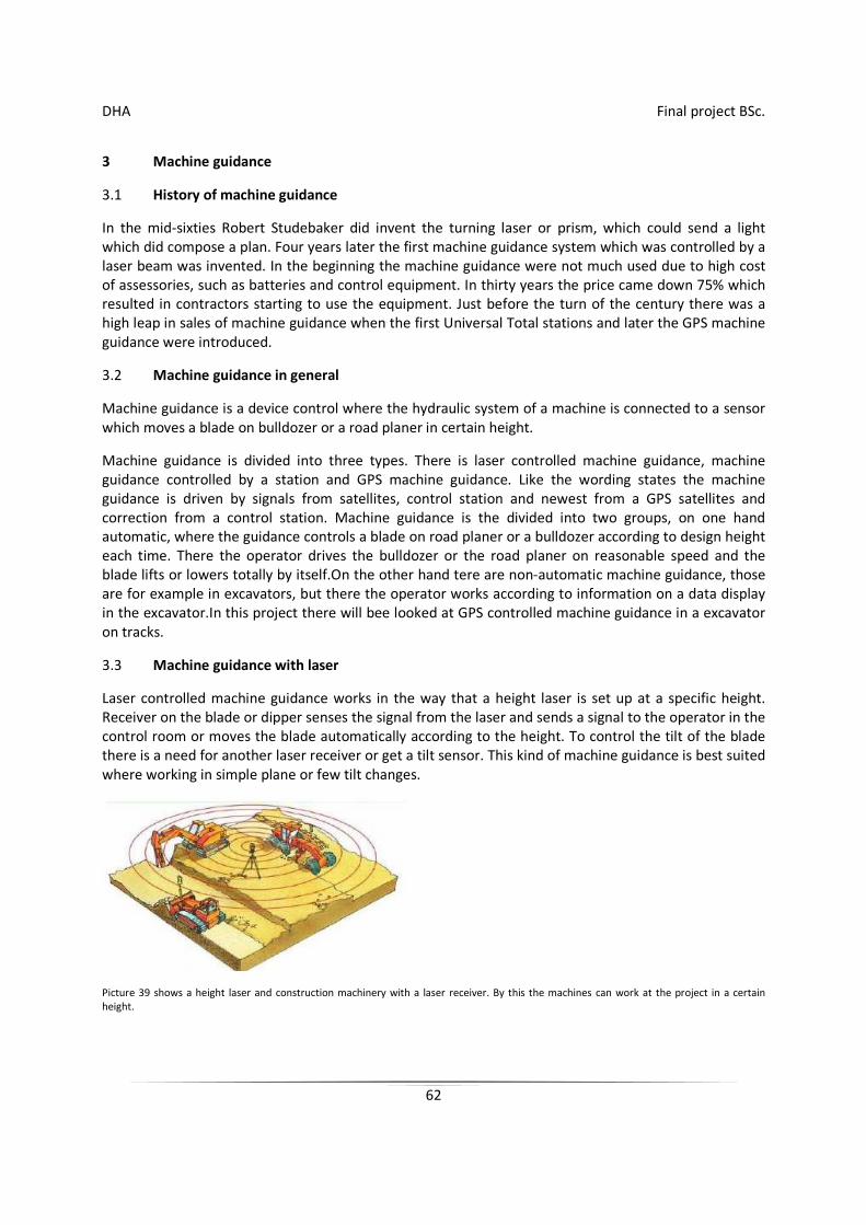
3.3 Machine guidance with laser
Laser controlled machine guidance works in the way that a height laser is set up at a specific height. Receiver on the blade or dipper senses the signal from the laser and sends a signal to the operator in the control room or moves the blade automatically according to the height. To control the tilt of the blade there is a need for another laser receiver or get a tilt sensor. This kind of machine guidance is best suited where working in simple plane or few tilt changes.
Picture 39 shows a height laser and construction machinery with a laser receiver. By this the machines can work at the project in a certain height.
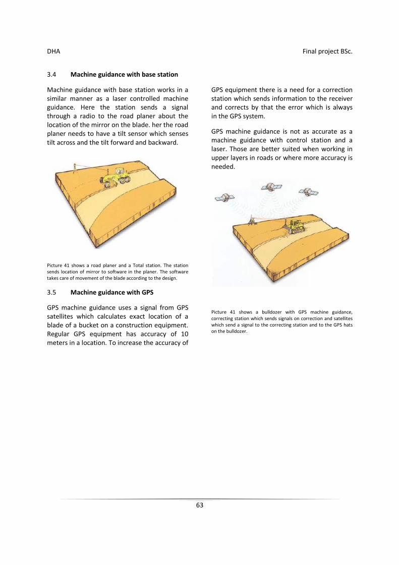
DHA Final project BSc.
63
3.4 Machine guidance with base station
Machine guidance with base station works in a similar manner as a laser controlled machine guidance. Here the station sends a signal through a radio to the road planer about the location of the mirror on the blade. her the road planer needs to have a tilt sensor which senses tilt across and the tilt forward and backward.
Picture 41 shows a road planer and a Total station. The station sends location of mirror to software in the planer. The software takes care of movement of the blade according to the design.
3.5 Machine guidance with GPS
GPS machine guidance uses a signal from GPS satellites which calculates exact location of a blade of a bucket on a construction equipment. Regular GPS equipment has accuracy of 10 meters in a location. To increase the accuracy of
GPS equipment there is a need for a correction station which sends information to the receiver and corrects by that the error which is always in the GPS system.
GPS machine guidance is not as accurate as a machine guidance with control station and a laser. Those are better suited when working in upper layers in roads or where more accuracy is needed.
Picture 41 shows a bulldozer with GPS machine guidance, correcting station which sends signals on correction and satellites which send a signal to the correcting station and to the GPS hats on the bulldozer.
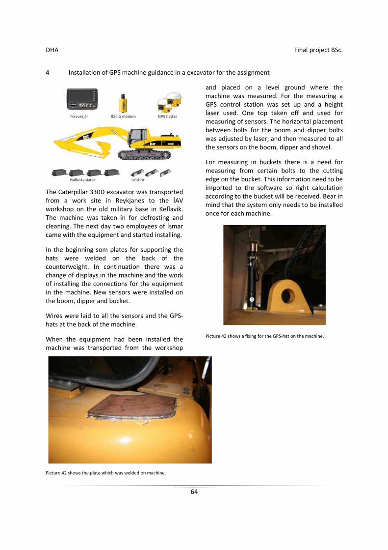
DHA Final project BSc.
64
4 Installation of GPS machine guidance in a excavator for the assignment
The Caterpillar 330D excavator was transported from a work site in Reykjanes to the ÍAV workshop on the old military base in Keflavík. The machine was taken in for defrosting and cleaning. The next day two employees of Ísmar came with the equipment and started installing.
In the beginning som plates for supporting the hats were welded on the back of the counterweight. In continuation there was a change of displays in the machine and the work of installing the connections for the equipment in the machine. New sensors were installed on the boom, dipper and bucket.
Wires were laid to all the sensors and the GPS-hats at the back of the machine.
When the equipment had been installed the machine was transported from the workshop
and placed on a level ground where the machine was measured. For the measuring a GPS control station was set up and a height laser used. One top taken off and used for measuring of sensors. The horizontal placement between bolts for the boom and dipper bolts was adjusted by laser, and then measured to all the sensors on the boom, dipper and shovel.
For measuring in buckets there is a need for measuring from certain bolts to the cutting edge on the bucket. This information need to be imported to the software so right calculation according to the bucket will be received. Bear in mind that the system only needs to be installed once for each machine.
Picture 43 shows a fixing for the GPS-hat on the machine.
Picture 42 shows the plate which was welded on machine.
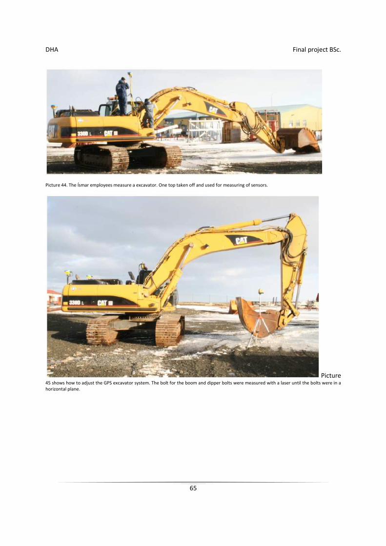
DHA Final project BSc.
65
Picture 44. The Ísmar employees measure a excavator. One top taken off and used for measuring of sensors.
Picture 45 shows how to adjust the GPS excavator system. The bolt for the boom and dipper bolts were measured with a laser until the bolts were in a horizontal plane.
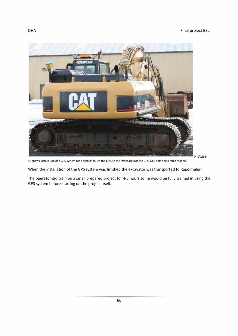
DHA Final project BSc.
66
Picture 46 shows installation of a GPS system for a excavator. On the picture the fastenings for the GPS, GPS hats and a radio modem.
When the installation of the GPS system was finished the excavator was transported to Rauðimelur.
The operator did train on a small prepared project for 4-5 hours so he would be fully trained in using the GPS system before starting on the project itself.
DHA Final project BSc.
67
5 Opinion
5.1 Contractors opinion on usage of machine guidance in construction equipment.
To get opinion on the machine guidance from contractors they did get a short questionnaire.
1. How much time is saved in certain projects by using satellite equipment in construction machinery instead of using a surveyor?
It depends totally on the nature of the projects, but if we use a typical road building as example, then we can say that generally the first stakeout of surveyor is to set up e center line, cutting edges and slope bottom.
The center line is without exception lost because the road fill covers this measurement. Measuring for the cutting edges is difficult to maintain when excavating for a road, but those are generally longest standing. Measuring for the slope bottom is also rather difficult to keep, because of fallout from fill when bulldozed. This will state that only 1/3 of original work of a surveyor can be used in the long term in the project, but this surveying is necessary so it is possible to start the project. What is done with a machine guidance that the operator takes a excavator or a bulldozer to the road site and marks the road site by driving with the blade down and by this marks the road site. Then the disruption can be seen in the landscape and other machines can work roughly by this lines although those machines are not equipped with machine guidance. Furthermore newer machine guidance systems are equipped so they can measure the surface to "calibrate" the volume afterwards. The work of the surveyor often is to re erect stakes which have fallen and by this keep the project within the staked measurement so right volume is used in the work and the contractor is not moving material he will not get paid for, and even needs removed at a extra cost. If taken as it is, then I presume that tere is a need for 4 times the stakeout of the whole project. 1 in the beginning, 2 stakeout of fillings and trenches, 3 stakeout of lower base layer and correction of slopes and cutting edges, 4 stakeout of top layer and final finishing. If we give that the surveyor with an assistant stakes out 3 to 4 km a day and uses stakes, markers on stakes, spray and such, then it is not unreasonable to say that this work can be cut by 2/3, because it not realistic to say that the work of a surveyor can be omitted, he is needed to prepare the machine guidance data and load those to the equipment and follow the project with control measuring. Then it is the question to take a made up example and calculate the savings in time by example a 20 km road. then the surveyor would be using a weeks work in each round, those would be four, then he would be working alongside a assistant for one month instead of using approx 12 days and not having a assistant and less cost to mark the stakeout.
2. What has the satellite equipment to offer, same possibilities as the surveyor is using or are there limitations?
The equipment has in itself the same possibilities but not as accurate as more factors do have effect on the accuracy of the machine guidance such as wear in the construction machinery which has the equipment, some inaccuracy can be because the operator is not a trained surveyor and so on. The limitation is to my judgement the person who is using the machine guidance, the better he is trained and better aware of the equipment he is working with thus less limitations are on what can be done.
3. How long is the payback time of the equipment, by this we mean the savings for the company due to enhanced production, savings in time and optimization?
DHA Final project BSc.
68
In ordinary construction equipment there is a calculated 60% write-off, this can not be done with technical equipment as machine guidance as there is fast evolution and innovations appear faster than in the construction equipment. I do think that it is normal to calculate 60% write-off in 2 years and use same preconditions to calculate the pay for the machine guidance. It is although so that such equipment can get a payback more than once in larger projects as all transport of material which is not paid for costs often double, first it needs to be transported to the site and the to be removed, as if tere is not paid for the transport then the material should not be where it is (excess fill), only lucky if it needs not to be taken back. Ordinary
Trimble machine guidance for a bulldozer which has self control possibilities cost approx 6 millions icl. kr installed, and if m3 does cost transported and finished about 1000 icl.kr then the machine guidance costs 6000 m3, 3000m3 in and 3000m3 out.
Large road fillings can be 20 to 30 thousand m3 and it can be given that a 20 km road could have 12500 m3/km in total removal and fillings which gives about 250 000 m3 in transport of material, then 6000 m3 is only 2,4% of the total fill, which easily is saved by machine guidance, together with the time savings, which often counts for more than the cost of transport of material as time is a limited resource to day where production speed is essential.
4. In what projects is the satellite equipment best suited and where not?
In short does the satellite equipment suit everywhere above ground, although not beneath steep walls of high rise buildings, in deep gorges and where something can block the receiver.
5. How is dealt with problems like limited number of satellites as happens often?
The position changes regularly and it is easy to foresee when a satellite will be missing so the project can be done with full accuracy, then it is easy to set up a reference in height and direction with the machine guidance itself, then it is easy to perform a accurate correction afterwards when the position of the satellites is back to normal, which last normal not longer than 3 hours at the time.
6. What does this mean for the operator who is using the equipment?
He needs to have already to adapted to respond as stated above, by the help of administrator or surveyor, if this shall not be a problem.
7. What does this mean for the surveyor?
He could have to assist the operator.
8. What does this mean for the company?
Nothing if above steps are followed.

DHA Final project BSc.
69
Sincerely
Þorvaldur Konráðsson
Building engineer and former employee of Arnarfell.


![INDEX [] Document Manpower Supply INST... · includes excavation and back filling of cable trench after laying of cable. SUPERVISION AND WORKFORCE: Contractor has to provide supervision](https://img.pdfslide.us/doc/110x75/5ebae372cdb475719e7ed431/index-document-manpower-supply-inst-includes-excavation-and-back-filling.jpg)