Embed Size (px)
Citation preview
Division of Environment Bureau of Water Municipal Programs Section Curtis State Office Building 1000 SW Jackson, Suite 420 Topeka, KS 66612-1367
Phone: 785-296-5527 Fax: 785-296-0086
[email protected] www.kdheks.gov
M E M O R A N D U M DATE: June 6, 2014 TO: Newton 2.1 File KWPCRF Project No.: C20 1747 03 FROM: Rod Geisler, PE, Chief Municipal Programs Section. SUBJECT: Newton, Kansas Project to Upgrade Existing Wastewater Treatment Facility EPA Green Project Reserve
Similar to the ARRA funding effort, the Federal Clean Water SRF funding provided in FFY 2010 and subsequent years requires a certain percentage of federal funding be targeted to provide for “Green Project Reserve” (GPR) designs. EPA wrote new guidance to define qualifying uses for the Green Project Reserve requirements for the FFY 2010 funding, dated April 21, 2010, which has been carried forward through FFY 2014 program funding. As stated on page 1, paragraph “II. GPR Goals.” The “intent” is “to guide funding toward projects that…enhance water and energy conservation…”. The project at Newton, Kansas, achieves this goal by substantially reducing energy usage in the entire wastewater treatment process by abandoning certain treatment processes, constructing new treatment processes, and upgrading all unit processes that remain from the old facilities. The loan agreement is dated Effective as of November 1, 2013.
The project being funded will construct a new biological treatment process (extended aeration activated sludge basin with anaerobic and anoxic chambers designed for biological nutrient removal), two additional final clarifiers, expansion of the ultraviolet effluent disinfection facility, conversion of the existing activated biosolids aeration basin to an aerated biosolids digester, installation of two additional aerated sludge digesters, a biosolids process building, biosolids storage bays, miscellaneous equipment replacement or relocation, and demolition of various structures at the present facility. A review of the GPR guidance as presented below indicates this project meets the requirements to qualify as a Green Project Reserve project in accordance with these Federal guidelines.
0.1 All GPR projects must otherwise be eligible for CWSRF funding. - The project at Newton is eligible.
0.2 All Section 212 projects must be consistent with the definition of “treatment works” as set forth in Section 212 of the Clean Water Act (CWA).
Newton 2.1 File Memo June 6, 2014 Page 2
- The project at Newton is a “Section 212” project, the wastewater treatment plant is publicly owned, and the project will have a direct water quality benefit by improving the efficiency and flexibility of the treatment process including effluent irrigation reuse, waste sludge storage, disposal, and reuse of biosolids from the treatment process.
0.3 Eligible non-point source projects… - NA. This is not a non-point source project. 0.4 Eligible projects under Section 320… - NA. This is not a Section 320 project. 0.5 GPR projects must meet the definition of one of the four GPR categories. - See below 0.6 GPR project must further the goals of the Clean Water Act. CWSRF Technical Guidance 1.0 Green infrastructure - NA 2.0 Water Efficiency - NA 3.0 Energy Efficiency 3.1 Definition: Energy efficiency is the use of improved technologies and practices to reduce
the energy consumption of water quality projects, use energy in a more efficient way, and/or produce/utilize renewable energy.
- The project at Newton achieves this goal by reducing energy consumption in wastewater
treatment and biosolids reuse. 3.2 Categorical Projects 3.2.1 Renewable energy projects such as wind, solar, geothermal, micro-hydroelectric, and
biogas combined heat and power systems (CHP) that provide power to a POTW. (http:///www.epa.gov/cleanenergy). Micro-hydroelectic projects involve capturing the energy from pipe flow.
- NA 3.2.2 Projects that achieve a 20% reduction in energy consumption are categorically eligible
for GPR4. Retrofit projects should compare energy used by the existing system or unit process to the proposed project. The energy used by the existing system should be based on name plate data when the system was first installed, recognizing that the old
Newton 2.1 File Memo June 6, 2014 Page 3
system is currently operating at a lower overall efficiency than at the time of installation. New POTW projects or capacity expansion projects should be designed to maximize energy efficiency and should select high efficiency premium motors and equipment where cost effective. Estimation of the energy efficiency is necessary for the project to be counted toward GPR. If a project achieves less than a 20% reduction in energy efficiency, then it may be justified using a business case.
4The 20% threshold for categorically eligible CWSRF energy efficiency projects was derived from a 2002 Department of Energy study entitled United States Industrial Electric Motor Systems Market Opportunities Assessment, December 2002 and adopted by the Consortium for Energy Efficiency. Further field studies conducted by Wisconsin Focus on Energy and other States programs support the threshold.
5A unit process is a portion of the wastewater system such as the collection system, pumping stations, aeration system, or solids handling, etc.
- The project at Newton meets this GPR qualifying criteria as the consulting engineer has conducted a comparison of energy use of the existing wastewater treatment facility processes and equipment to the upgraded treatment processes and equipment. A copy of the calculations memo from the consulting engineer email dated June 6, 2014 is attached to this memo. A copy of the Design Memorandum dated October 5, 2102 is also attached to this memo.
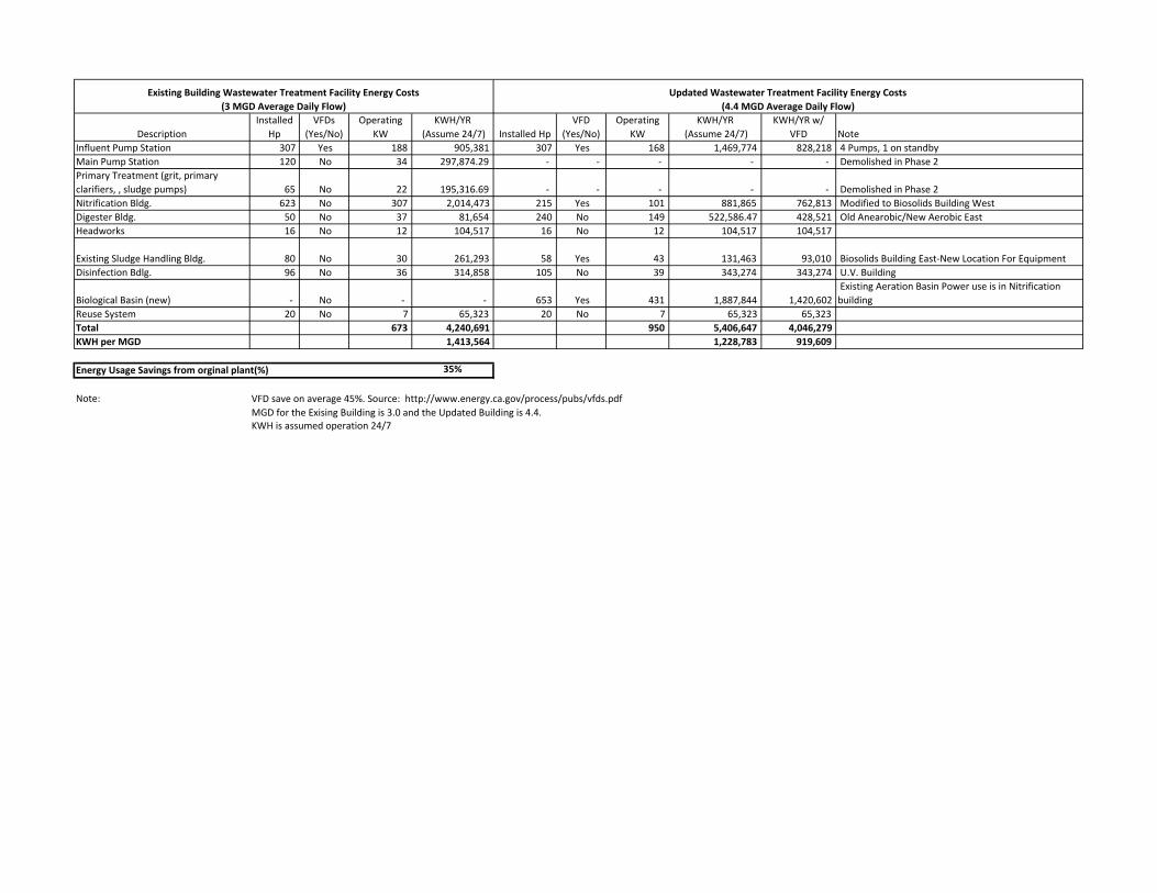
The consulting engineer has compared energy use in the form of electricity by the “common denominator” of KWH per MGD of sewage treated. The current treatment project is using 1,413,564 KWH of electricity per MGD of sewage flow treated. The upgraded treatment process is designed and estimated to use 919,609 KWH per MGD of sewage flow treated. By these numbers, the project at Newton will reduce energy usage by (1,413,564 KWH per MGD treated - 919,609 KWH per MGD treated) / 1,413,564 KWH per MGD treated = 35%, which exceeds the minimum 20% threshold in the EPA guidance for a “categorical” GPR project determination. 3.2-3 Collection system Infiltration/Inflow (l/l) detection equipment - NA 3.2.4 POTW energy management planning… - NA 3.3 Projects that do not meet the definition of Energy Efficiency. - NA 3.4 Decision Criteria for Business Cases - NA
Newton 2.1 File Memo June 6, 2014 Page 4
3.5 Examples of Projects Requiring a Business Case - NA 4.0 Environmentally Innovative - NA Therefore, the project at Newton meets the EPA definition of being “categorically” green. The as-bid construction cost of Phase 2 of the project, which reflects the energy savings presented above, is $17,226,585. The entire Phase 2 cost is considered a qualifying cost under the EPA Green Project Reserve. Attached Newton Wastewater Energy Report (2 pp) Copy of Design Memorandum dated October 5, 2012 (13 pp) Reference FFY 2010 EPA GPR Guidance Pc: Rance Walker, Rod Geisler

From: Alicia Warren [mailto:[email protected]] Sent: Friday, June 06, 2014 11:21 AM To: Rod Geisler Cc: Sarah Unruh; Lynn Moore Subject: GRP Memo and analysis Rod, Here is the information on Newton WWTP improvements Phase 2 project for energy analysis. The comparison includes expected run times not just equipment running full speed 100% of the time. Let me know if you have any questions. Thanks,
Alicia Warren, IE Municipal Division 316-262-2691 Direct 316-206-1394 [email protected]
Professional Engineering Consultants, P.A. 303 South Topeka Wichita, KS 67202 316-262-2691 www.pec1.com
This e-mail and any files transmitted with it are confidential and intended solely for the use of the individual or entity to whom they are addressed. If you have received this email in error please notify the sender. If you are not the named addressee you should not disseminate, distribute or copy this e-mail. Please notify the sender immediately by e-mail if you have received this e-mail by mistake and delete this e-mail from your system. If you are not the intended recipient, you are hereby notified that disclosing, copying, distributing or taking any action in reliance on the contents of this e-mail is strictly prohibited.
DescriptionInstalled
HpVFDs
(Yes/No)Operating
KWKWH/YR
(Assume 24/7) Installed HpVFD
(Yes/No)Operating
KWKWH/YR
(Assume 24/7)KWH/YR w/
VFD NoteInfluent Pump Station 307 Yes 188 905,381 307 Yes 168 1,469,774 828,218 4 Pumps, 1 on standby Main Pump Station 120 No 34 297,874.29 ‐ ‐ ‐ ‐ ‐ Demolished in Phase 2 Primary Treatment (grit, primary clarifiers, , sludge pumps) 65 No 22 195,316.69 ‐ ‐ ‐ ‐ ‐ Demolished in Phase 2 Nitrification Bldg. 623 No 307 2,014,473 215 Yes 101 881,865 762,813 Modified to Biosolids Building West Digester Bldg. 50 No 37 81,654 240 No 149 522,586.47 428,521 Old Anearobic/New Aerobic East Headworks 16 No 12 104,517 16 No 12 104,517 104,517
Existing Sludge Handling Bldg. 80 No 30 261,293 58 Yes 43 131,463 93,010 Biosolids Building East‐New Location For Equipment Disinfection Bdlg. 96 No 36 314,858 105 No 39 343,274 343,274 U.V. Building
Biological Basin (new) ‐ No ‐ ‐ 653 Yes 431 1,887,844 1,420,602 Existing Aeration Basin Power use is in Nitrification building
Reuse System 20 No 7 65,323 20 No 7 65,323 65,323 Total 673 4,240,691 950 5,406,647 4,046,279 KWH per MGD 1,413,564 1,228,783 919,609
Energy Usage Savings from orginal plant(%) 35%
Note: VFD save on average 45%. Source: http://www.energy.ca.gov/process/pubs/vfds.pdfMGD for the Exising Building is 3.0 and the Updated Building is 4.4.KWH is assumed operation 24/7
Updated Wastewater Treatment Facility Energy Costs (4.4 MGD Average Daily Flow)
Existing Building Wastewater Treatment Facility Energy Costs (3 MGD Average Daily Flow)
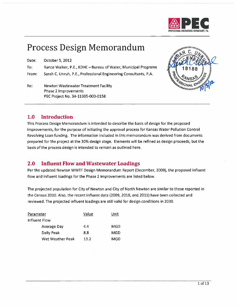
Process Design Memorandum Date: October 5, 2012 Project No. 34-11305-003-0158
2 of 13
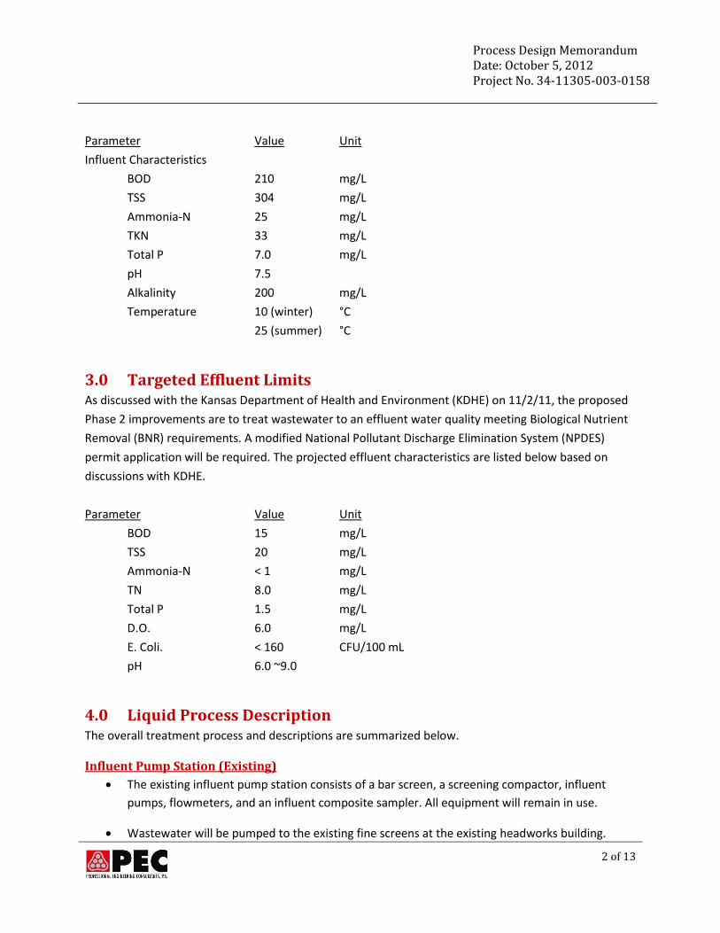
Parameter Value Unit
Influent Characteristics
BOD 210 mg/L
TSS 304 mg/L
Ammonia-N 25 mg/L
TKN 33 mg/L
Total P 7.0 mg/L
pH 7.5
Alkalinity 200 mg/L
Temperature 10 (winter) °C
25 (summer) °C
3.0 Targeted Effluent Limits As discussed with the Kansas Department of Health and Environment (KDHE) on 11/2/11, the proposed
Phase 2 improvements are to treat wastewater to an effluent water quality meeting Biological Nutrient
Removal (BNR) requirements. A modified National Pollutant Discharge Elimination System (NPDES)
permit application will be required. The projected effluent characteristics are listed below based on
discussions with KDHE.
Parameter Value Unit
BOD 15 mg/L
TSS 20 mg/L
Ammonia-N < 1 mg/L
TN 8.0 mg/L
Total P 1.5 mg/L
D.O. 6.0 mg/L
E. Coli. < 160 CFU/100 mL
pH 6.0 ~9.0
4.0 Liquid Process Description The overall treatment process and descriptions are summarized below.
Influent Pump Station (Existing)
The existing influent pump station consists of a bar screen, a screening compactor, influent
pumps, flowmeters, and an influent composite sampler. All equipment will remain in use.
Wastewater will be pumped to the existing fine screens at the existing headworks building.
Process Design Memorandum Date: October 5, 2012 Project No. 34-11305-003-0158
3 of 13
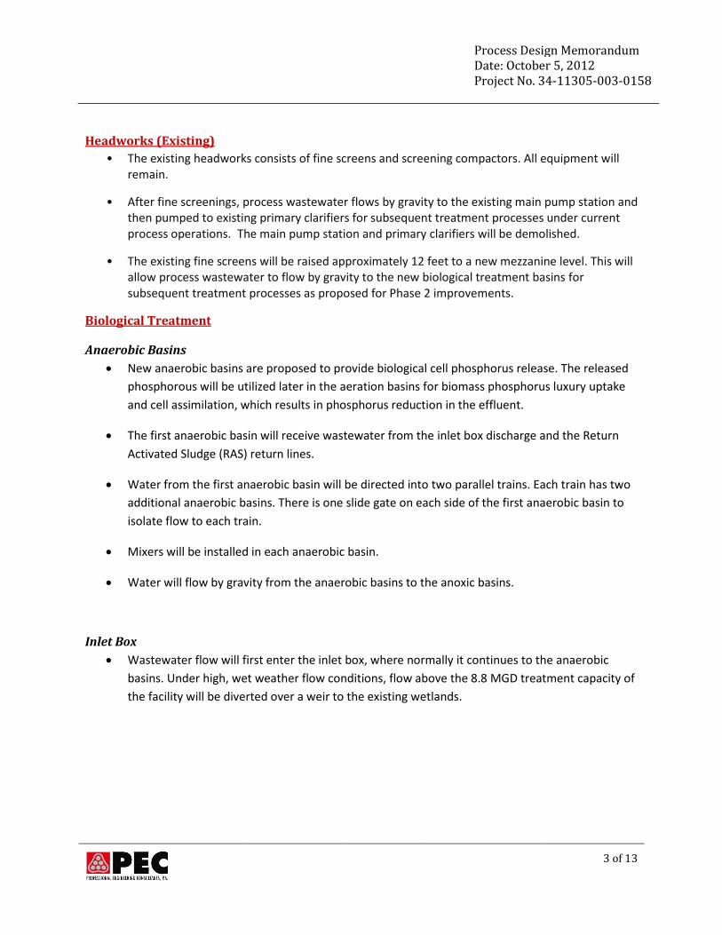
Headworks (Existing)
• The existing headworks consists of fine screens and screening compactors. All equipment will remain.
• After fine screenings, process wastewater flows by gravity to the existing main pump station and then pumped to existing primary clarifiers for subsequent treatment processes under current process operations. The main pump station and primary clarifiers will be demolished.
• The existing fine screens will be raised approximately 12 feet to a new mezzanine level. This will allow process wastewater to flow by gravity to the new biological treatment basins for subsequent treatment processes as proposed for Phase 2 improvements.
Biological Treatment
Anaerobic Basins
New anaerobic basins are proposed to provide biological cell phosphorus release. The released
phosphorous will be utilized later in the aeration basins for biomass phosphorus luxury uptake
and cell assimilation, which results in phosphorus reduction in the effluent.
The first anaerobic basin will receive wastewater from the inlet box discharge and the Return
Activated Sludge (RAS) return lines.
Water from the first anaerobic basin will be directed into two parallel trains. Each train has two
additional anaerobic basins. There is one slide gate on each side of the first anaerobic basin to
isolate flow to each train.
Mixers will be installed in each anaerobic basin.
Water will flow by gravity from the anaerobic basins to the anoxic basins.
Inlet Box
Wastewater flow will first enter the inlet box, where normally it continues to the anaerobic
basins. Under high, wet weather flow conditions, flow above the 8.8 MGD treatment capacity of
the facility will be diverted over a weir to the existing wetlands.
Process Design Memorandum Date: October 5, 2012 Project No. 34-11305-003-0158
4 of 13
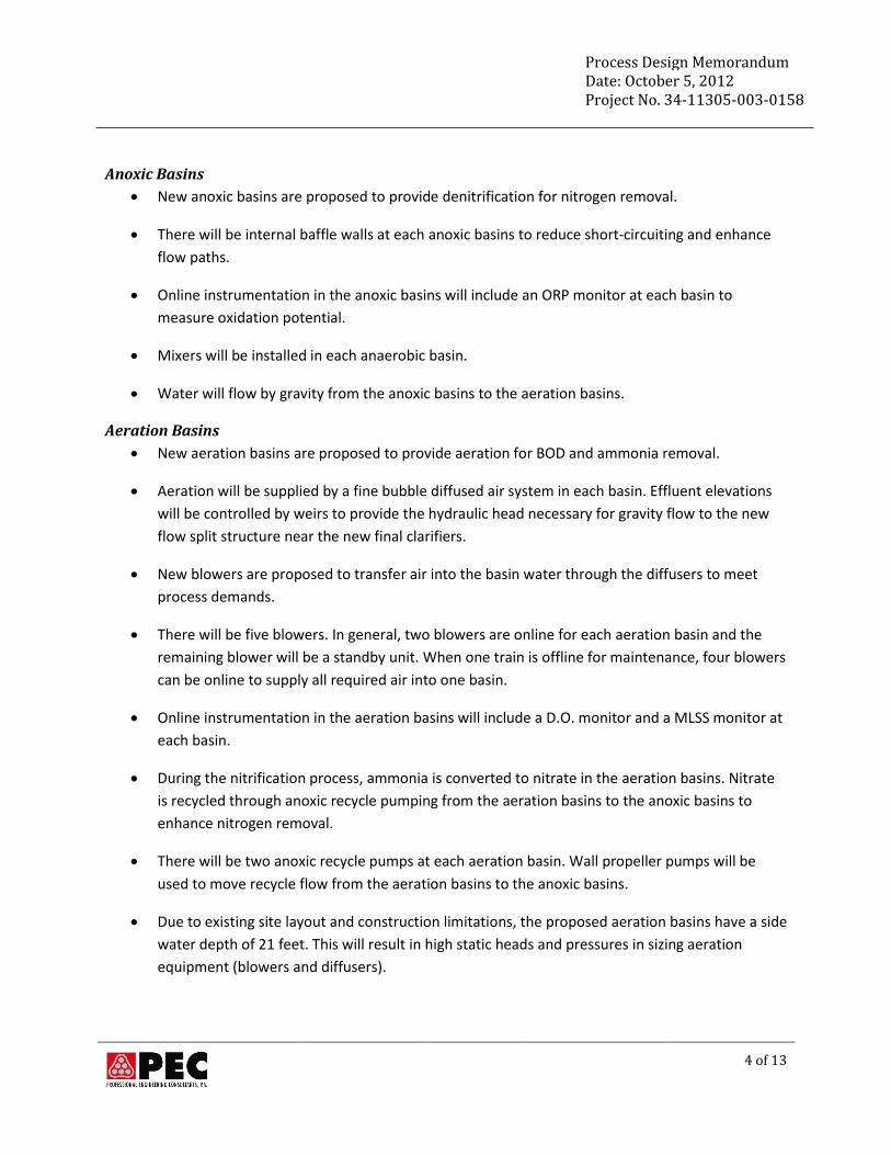
Anoxic Basins
New anoxic basins are proposed to provide denitrification for nitrogen removal.
There will be internal baffle walls at each anoxic basins to reduce short-circuiting and enhance
flow paths.
Online instrumentation in the anoxic basins will include an ORP monitor at each basin to
measure oxidation potential.
Mixers will be installed in each anaerobic basin.
Water will flow by gravity from the anoxic basins to the aeration basins.
Aeration Basins
New aeration basins are proposed to provide aeration for BOD and ammonia removal.
Aeration will be supplied by a fine bubble diffused air system in each basin. Effluent elevations
will be controlled by weirs to provide the hydraulic head necessary for gravity flow to the new
flow split structure near the new final clarifiers.
New blowers are proposed to transfer air into the basin water through the diffusers to meet
process demands.
There will be five blowers. In general, two blowers are online for each aeration basin and the
remaining blower will be a standby unit. When one train is offline for maintenance, four blowers
can be online to supply all required air into one basin.
Online instrumentation in the aeration basins will include a D.O. monitor and a MLSS monitor at
each basin.
During the nitrification process, ammonia is converted to nitrate in the aeration basins. Nitrate
is recycled through anoxic recycle pumping from the aeration basins to the anoxic basins to
enhance nitrogen removal.
There will be two anoxic recycle pumps at each aeration basin. Wall propeller pumps will be
used to move recycle flow from the aeration basins to the anoxic basins.
Due to existing site layout and construction limitations, the proposed aeration basins have a side
water depth of 21 feet. This will result in high static heads and pressures in sizing aeration
equipment (blowers and diffusers).
Process Design Memorandum Date: October 5, 2012 Project No. 34-11305-003-0158
5 of 13
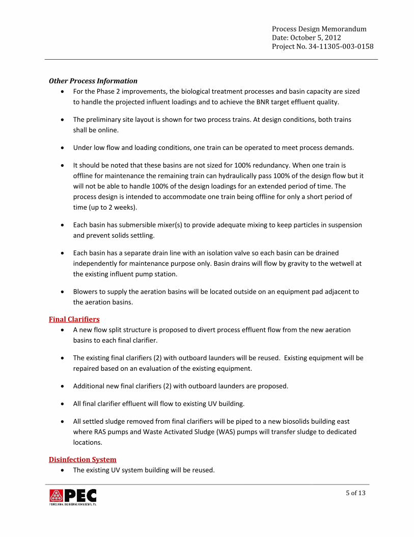
Other Process Information
For the Phase 2 improvements, the biological treatment processes and basin capacity are sized
to handle the projected influent loadings and to achieve the BNR target effluent quality.
The preliminary site layout is shown for two process trains. At design conditions, both trains
shall be online.
Under low flow and loading conditions, one train can be operated to meet process demands.
It should be noted that these basins are not sized for 100% redundancy. When one train is
offline for maintenance the remaining train can hydraulically pass 100% of the design flow but it
will not be able to handle 100% of the design loadings for an extended period of time. The
process design is intended to accommodate one train being offline for only a short period of
time (up to 2 weeks).
Each basin has submersible mixer(s) to provide adequate mixing to keep particles in suspension
and prevent solids settling.
Each basin has a separate drain line with an isolation valve so each basin can be drained
independently for maintenance purpose only. Basin drains will flow by gravity to the wetwell at
the existing influent pump station.
Blowers to supply the aeration basins will be located outside on an equipment pad adjacent to
the aeration basins.
Final Clarifiers
A new flow split structure is proposed to divert process effluent flow from the new aeration
basins to each final clarifier.
The existing final clarifiers (2) with outboard launders will be reused. Existing equipment will be
repaired based on an evaluation of the existing equipment.
Additional new final clarifiers (2) with outboard launders are proposed.
All final clarifier effluent will flow to existing UV building.
All settled sludge removed from final clarifiers will be piped to a new biosolids building east
where RAS pumps and Waste Activated Sludge (WAS) pumps will transfer sludge to dedicated
locations.
Disinfection System
The existing UV system building will be reused.
Process Design Memorandum Date: October 5, 2012 Project No. 34-11305-003-0158
6 of 13
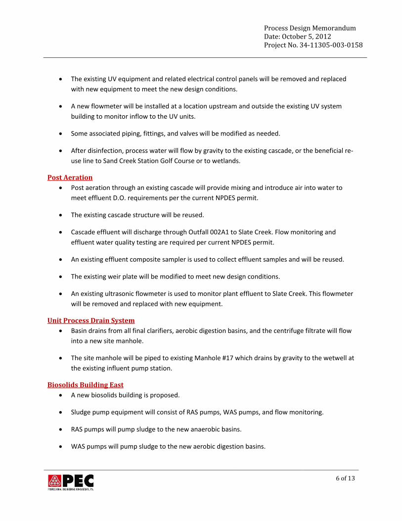
The existing UV equipment and related electrical control panels will be removed and replaced
with new equipment to meet the new design conditions.
A new flowmeter will be installed at a location upstream and outside the existing UV system
building to monitor inflow to the UV units.
Some associated piping, fittings, and valves will be modified as needed.
After disinfection, process water will flow by gravity to the existing cascade, or the beneficial re-
use line to Sand Creek Station Golf Course or to wetlands.
Post Aeration
Post aeration through an existing cascade will provide mixing and introduce air into water to
meet effluent D.O. requirements per the current NPDES permit.
The existing cascade structure will be reused.
Cascade effluent will discharge through Outfall 002A1 to Slate Creek. Flow monitoring and
effluent water quality testing are required per current NPDES permit.
An existing effluent composite sampler is used to collect effluent samples and will be reused.
The existing weir plate will be modified to meet new design conditions.
An existing ultrasonic flowmeter is used to monitor plant effluent to Slate Creek. This flowmeter
will be removed and replaced with new equipment.
Unit Process Drain System
Basin drains from all final clarifiers, aerobic digestion basins, and the centrifuge filtrate will flow
into a new site manhole.
The site manhole will be piped to existing Manhole #17 which drains by gravity to the wetwell at
the existing influent pump station.
Biosolids Building East
A new biosolids building is proposed.
Sludge pump equipment will consist of RAS pumps, WAS pumps, and flow monitoring.
RAS pumps will pump sludge to the new anaerobic basins.
WAS pumps will pump sludge to the new aerobic digestion basins.
Process Design Memorandum Date: October 5, 2012 Project No. 34-11305-003-0158
7 of 13
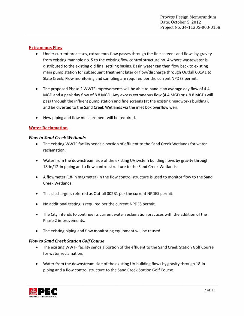
Extraneous Flow
Under current processes, extraneous flow passes through the fine screens and flows by gravity
from existing manhole no. 5 to the existing flow control structure no. 4 where wastewater is
distributed to the existing old final settling basins. Basin water can then flow back to existing
main pump station for subsequent treatment later or flow/discharge through Outfall 001A1 to
Slate Creek. Flow monitoring and sampling are required per the current NPDES permit.
The proposed Phase 2 WWTF improvements will be able to handle an average day flow of 4.4
MGD and a peak day flow of 8.8 MGD. Any excess extraneous flow (4.4 MGD or > 8.8 MGD) will
pass through the influent pump station and fine screens (at the existing headworks building),
and be diverted to the Sand Creek Wetlands via the inlet box overflow weir.
New piping and flow measurement will be required.
Water Reclamation
Flow to Sand Creek Wetlands
The existing WWTF facility sends a portion of effluent to the Sand Creek Wetlands for water
reclamation.
Water from the downstream side of the existing UV system building flows by gravity through
18-in/12-in piping and a flow control structure to the Sand Creek Wetlands.
A flowmeter (18-in magmeter) in the flow control structure is used to monitor flow to the Sand
Creek Wetlands.
This discharge is referred as Outfall 002B1 per the current NPDES permit.
No additional testing is required per the current NPDES permit.
The City intends to continue its current water reclamation practices with the addition of the
Phase 2 improvements.
The existing piping and flow monitoring equipment will be reused.
Flow to Sand Creek Station Golf Course
The existing WWTF facility sends a portion of the effluent to the Sand Creek Station Golf Course
for water reclamation.
Water from the downstream side of the existing UV building flows by gravity through 18-in
piping and a flow control structure to the Sand Creek Station Golf Course.
Process Design Memorandum Date: October 5, 2012 Project No. 34-11305-003-0158
8 of 13
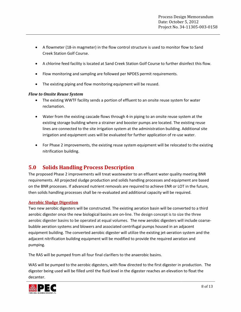
A flowmeter (18-in magmeter) in the flow control structure is used to monitor flow to Sand
Creek Station Golf Course.
A chlorine feed facility is located at Sand Creek Station Golf Course to further disinfect this flow.
Flow monitoring and sampling are followed per NPDES permit requirements.
The existing piping and flow monitoring equipment will be reused.
Flow to Onsite Reuse System
The existing WWTF facility sends a portion of effluent to an onsite reuse system for water
reclamation.
Water from the existing cascade flows through 4-in piping to an onsite reuse system at the
existing storage building where a strainer and booster pumps are located. The existing reuse
lines are connected to the site irrigation system at the administration building. Additional site
irrigation and equipment uses will be evaluated for further application of re-use water.
For Phase 2 improvements, the existing reuse system equipment will be relocated to the existing
nitrification building.
5.0 Solids Handling Process Description The proposed Phase 2 improvements will treat wastewater to an effluent water quality meeting BNR
requirements. All projected sludge production and solids handling processes and equipment are based
on the BNR processes. If advanced nutrient removals are required to achieve ENR or LOT in the future,
then solids handling processes shall be re-evaluated and additional capacity will be required.
Aerobic Sludge Digestion
Two new aerobic digesters will be constructed. The existing aeration basin will be converted to a third
aerobic digester once the new biological basins are on-line. The design concept is to size the three
aerobic digester basins to be operated at equal volumes. The new aerobic digesters will include coarse-
bubble aeration systems and blowers and associated centrifugal pumps housed in an adjacent
equipment building. The converted aerobic digester will utilize the existing jet-aeration system and the
adjacent nitrification building equipment will be modified to provide the required aeration and
pumping.
The RAS will be pumped from all four final clarifiers to the anaerobic basins.
WAS will be pumped to the aerobic digesters, with flow directed to the first digester in production. The
digester being used will be filled until the fluid level in the digester reaches an elevation to float the
decanter.
Process Design Memorandum Date: October 5, 2012 Project No. 34-11305-003-0158
9 of 13
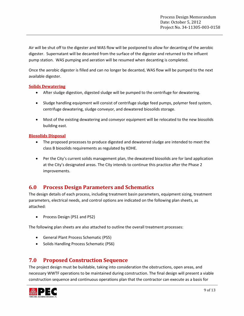
Air will be shut off to the digester and WAS flow will be postponed to allow for decanting of the aerobic
digester. Supernatant will be decanted from the surface of the digester and returned to the influent
pump station. WAS pumping and aeration will be resumed when decanting is completed.
Once the aerobic digester is filled and can no longer be decanted, WAS flow will be pumped to the next
available digester.
Solids Dewatering
After sludge digestion, digested sludge will be pumped to the centrifuge for dewatering.
Sludge handling equipment will consist of centrifuge sludge feed pumps, polymer feed system,
centrifuge dewatering, sludge conveyor, and dewatered biosolids storage.
Most of the existing dewatering and conveyor equipment will be relocated to the new biosolids
building east.
Biosolids Disposal
The proposed processes to produce digested and dewatered sludge are intended to meet the
class B biosolids requirements as regulated by KDHE.
Per the City’s current solids management plan, the dewatered biosolids are for land application
at the City’s designated areas. The City intends to continue this practice after the Phase 2
improvements.
6.0 Process Design Parameters and Schematics The design details of each process, including treatment basin parameters, equipment sizing, treatment
parameters, electrical needs, and control options are indicated on the following plan sheets, as
attached:
Process Design (PS1 and PS2)
The following plan sheets are also attached to outline the overall treatment processes:
General Plant Process Schematic (PS5)
Solids Handling Process Schematic (PS6)
7.0 Proposed Construction Sequence The project design must be buildable, taking into consideration the obstructions, open areas, and
necessary WWTF operations to be maintained during construction. The final design will present a viable
construction sequence and continuous operations plan that the contractor can execute as a basis for
Process Design Memorandum Date: October 5, 2012 Project No. 34-11305-003-0158
10 of 13
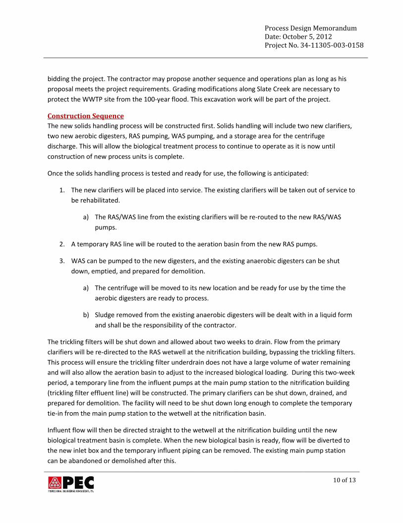
bidding the project. The contractor may propose another sequence and operations plan as long as his
proposal meets the project requirements. Grading modifications along Slate Creek are necessary to
protect the WWTP site from the 100-year flood. This excavation work will be part of the project.
Construction Sequence
The new solids handling process will be constructed first. Solids handling will include two new clarifiers,
two new aerobic digesters, RAS pumping, WAS pumping, and a storage area for the centrifuge
discharge. This will allow the biological treatment process to continue to operate as it is now until
construction of new process units is complete.
Once the solids handling process is tested and ready for use, the following is anticipated:
1. The new clarifiers will be placed into service. The existing clarifiers will be taken out of service to
be rehabilitated.
a) The RAS/WAS line from the existing clarifiers will be re-routed to the new RAS/WAS
pumps.
2. A temporary RAS line will be routed to the aeration basin from the new RAS pumps.
3. WAS can be pumped to the new digesters, and the existing anaerobic digesters can be shut
down, emptied, and prepared for demolition.
a) The centrifuge will be moved to its new location and be ready for use by the time the
aerobic digesters are ready to process.
b) Sludge removed from the existing anaerobic digesters will be dealt with in a liquid form
and shall be the responsibility of the contractor.
The trickling filters will be shut down and allowed about two weeks to drain. Flow from the primary
clarifiers will be re-directed to the RAS wetwell at the nitrification building, bypassing the trickling filters.
This process will ensure the trickling filter underdrain does not have a large volume of water remaining
and will also allow the aeration basin to adjust to the increased biological loading. During this two-week
period, a temporary line from the influent pumps at the main pump station to the nitrification building
(trickling filter effluent line) will be constructed. The primary clarifiers can be shut down, drained, and
prepared for demolition. The facility will need to be shut down long enough to complete the temporary
tie-in from the main pump station to the wetwell at the nitrification basin.
Influent flow will then be directed straight to the wetwell at the nitrification building until the new
biological treatment basin is complete. When the new biological basin is ready, flow will be diverted to
the new inlet box and the temporary influent piping can be removed. The existing main pump station
can be abandoned or demolished after this.
Process Design Memorandum Date: October 5, 2012 Project No. 34-11305-003-0158
11 of 13
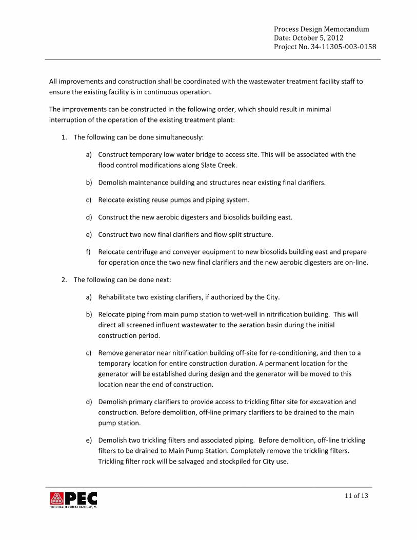
All improvements and construction shall be coordinated with the wastewater treatment facility staff to
ensure the existing facility is in continuous operation.
The improvements can be constructed in the following order, which should result in minimal
interruption of the operation of the existing treatment plant:
1. The following can be done simultaneously:
a) Construct temporary low water bridge to access site. This will be associated with the
flood control modifications along Slate Creek.
b) Demolish maintenance building and structures near existing final clarifiers.
c) Relocate existing reuse pumps and piping system.
d) Construct the new aerobic digesters and biosolids building east.
e) Construct two new final clarifiers and flow split structure.
f) Relocate centrifuge and conveyer equipment to new biosolids building east and prepare
for operation once the two new final clarifiers and the new aerobic digesters are on-line.
2. The following can be done next:
a) Rehabilitate two existing clarifiers, if authorized by the City.
b) Relocate piping from main pump station to wet-well in nitrification building. This will
direct all screened influent wastewater to the aeration basin during the initial
construction period.
c) Remove generator near nitrification building off-site for re-conditioning, and then to a
temporary location for entire construction duration. A permanent location for the
generator will be established during design and the generator will be moved to this
location near the end of construction.
d) Demolish primary clarifiers to provide access to trickling filter site for excavation and
construction. Before demolition, off-line primary clarifiers to be drained to the main
pump station.
e) Demolish two trickling filters and associated piping. Before demolition, off-line trickling
filters to be drained to Main Pump Station. Completely remove the trickling filters.
Trickling filter rock will be salvaged and stockpiled for City use.
Process Design Memorandum Date: October 5, 2012 Project No. 34-11305-003-0158
12 of 13
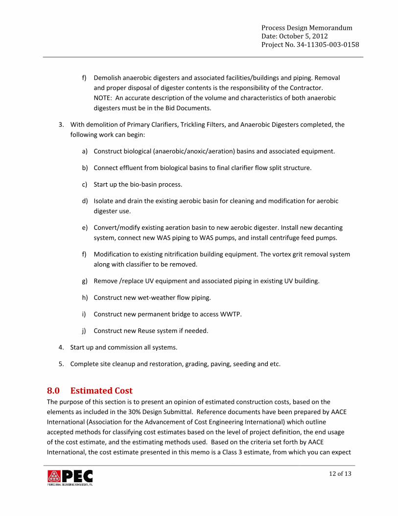
f) Demolish anaerobic digesters and associated facilities/buildings and piping. Removal
and proper disposal of digester contents is the responsibility of the Contractor.
NOTE: An accurate description of the volume and characteristics of both anaerobic
digesters must be in the Bid Documents.
3. With demolition of Primary Clarifiers, Trickling Filters, and Anaerobic Digesters completed, the
following work can begin:
a) Construct biological (anaerobic/anoxic/aeration) basins and associated equipment.
b) Connect effluent from biological basins to final clarifier flow split structure.
c) Start up the bio-basin process.
d) Isolate and drain the existing aerobic basin for cleaning and modification for aerobic
digester use.
e) Convert/modify existing aeration basin to new aerobic digester. Install new decanting
system, connect new WAS piping to WAS pumps, and install centrifuge feed pumps.
f) Modification to existing nitrification building equipment. The vortex grit removal system
along with classifier to be removed.
g) Remove /replace UV equipment and associated piping in existing UV building.
h) Construct new wet-weather flow piping.
i) Construct new permanent bridge to access WWTP.
j) Construct new Reuse system if needed.
4. Start up and commission all systems.
5. Complete site cleanup and restoration, grading, paving, seeding and etc.
8.0 Estimated Cost The purpose of this section is to present an opinion of estimated construction costs, based on the
elements as included in the 30% Design Submittal. Reference documents have been prepared by AACE
International (Association for the Advancement of Cost Engineering International) which outline
accepted methods for classifying cost estimates based on the level of project definition, the end usage
of the cost estimate, and the estimating methods used. Based on the criteria set forth by AACE
International, the cost estimate presented in this memo is a Class 3 estimate, from which you can expect
Process Design Memorandum Date: October 5, 2012 Project No. 34-11305-003-0158
13 of 13
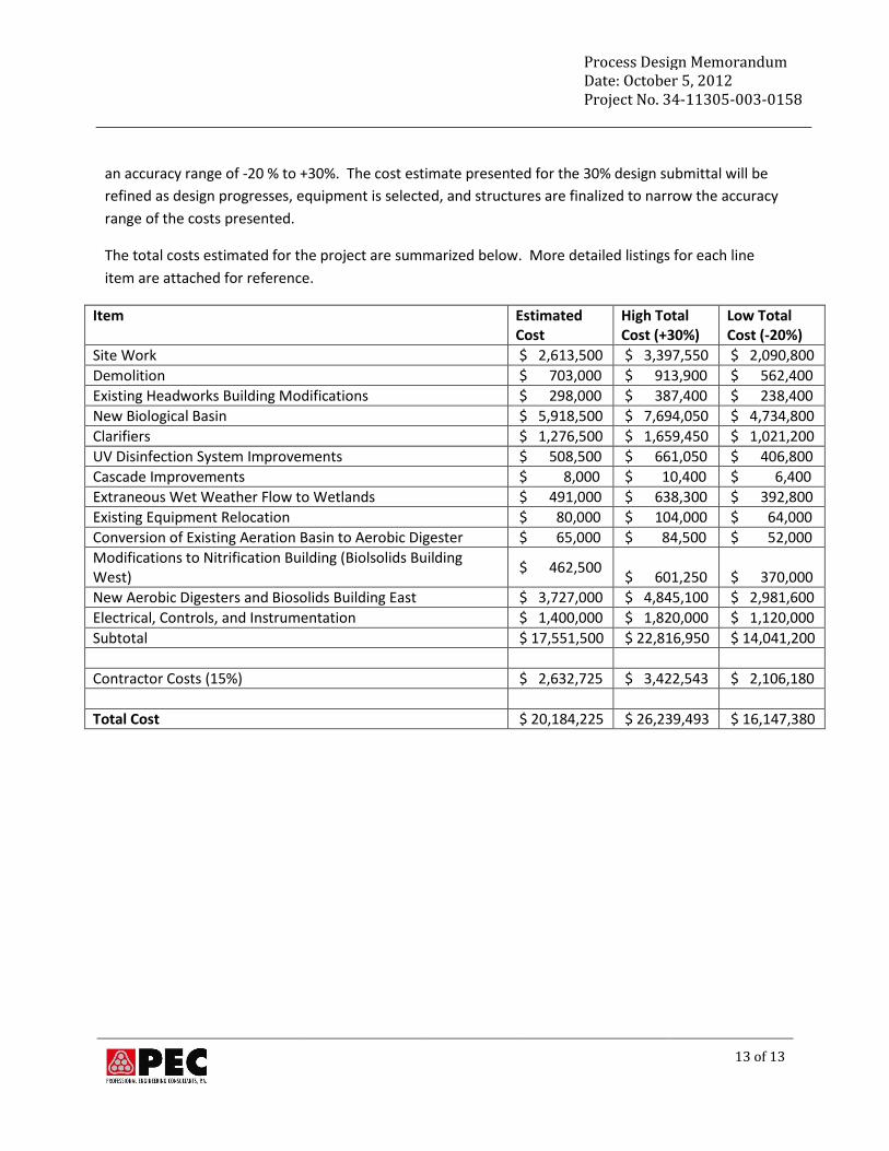
an accuracy range of -20 % to +30%. The cost estimate presented for the 30% design submittal will be
refined as design progresses, equipment is selected, and structures are finalized to narrow the accuracy
range of the costs presented.
The total costs estimated for the project are summarized below. More detailed listings for each line
item are attached for reference.
Item
Estimated Cost
High Total Cost (+30%)
Low Total Cost (-20%)
Site Work $ 2,613,500 $ 3,397,550 $ 2,090,800
Demolition $ 703,000 $ 913,900 $ 562,400
Existing Headworks Building Modifications $ 298,000 $ 387,400 $ 238,400
New Biological Basin $ 5,918,500 $ 7,694,050 $ 4,734,800
Clarifiers $ 1,276,500 $ 1,659,450 $ 1,021,200
UV Disinfection System Improvements $ 508,500 $ 661,050 $ 406,800
Cascade Improvements $ 8,000 $ 10,400 $ 6,400
Extraneous Wet Weather Flow to Wetlands $ 491,000 $ 638,300 $ 392,800
Existing Equipment Relocation $ 80,000 $ 104,000 $ 64,000
Conversion of Existing Aeration Basin to Aerobic Digester $ 65,000 $ 84,500 $ 52,000
Modifications to Nitrification Building (Biolsolids Building West)
$ 462,500 $ 601,250 $ 370,000
New Aerobic Digesters and Biosolids Building East $ 3,727,000 $ 4,845,100 $ 2,981,600
Electrical, Controls, and Instrumentation $ 1,400,000 $ 1,820,000 $ 1,120,000
Subtotal $ 17,551,500 $ 22,816,950 $ 14,041,200
Contractor Costs (15%) $ 2,632,725 $ 3,422,543 $ 2,106,180
Total Cost $ 20,184,225 $ 26,239,493 $ 16,147,380