Embed Size (px)
Citation preview
GPON OLT USER MANUAL(WEB Management)
Version V2.0.1
Release Date 2017-08-08
1 / 94
Contents
Chapter 1 System Description...............................................................................................5
1.1 Overview............................................................................................................5
1.1.1 OLT Introduction.....................................................................................................5
1.1.2 PC System Requirement..........................................................................................6
1.2 Connection......................................................................................................................7
Chapter 2 OLT Information......................................................................................................8
2.1 Login..............................................................................................................................8
2.2 Device Information.........................................................................................................8
Chapter 3 OLT Configuration.................................................................................................10
3.1 VLAN...........................................................................................................................10
3.1.1 Create VLAN.........................................................................................................11
3.1.2 VLAN Port.............................................................................................................11
3.1.3 QinQ/Translation...................................................................................................12
3.2 Uplink Port...................................................................................................................13
3.2.1 Information............................................................................................................13
3.2.2 Configuration.........................................................................................................14
3.3 PON..............................................................................................................................15
3.3.1 Information............................................................................................................15
3.3.2 Configuration.........................................................................................................16
3.4 MAC.............................................................................................................................17
3.4.1 MAC Table............................................................................................................17
3.4.2 Configuration.........................................................................................................18
3.5 LACP............................................................................................................................19
3.6 QOS..............................................................................................................................20
3.7 ACL..............................................................................................................................21
3.7.1 IP Filter..................................................................................................................21
3.7.2 MAC Filter.............................................................................................................22
3.7.3 IP/MAC Filter........................................................................................................23
3.7.4 Effect Filter............................................................................................................23
2 / 94
3.8 IGMP............................................................................................................................24
3.8.1 Group Member.......................................................................................................24
3.8.2 Global....................................................................................................................25
3.8.3 Port........................................................................................................................26
3.8.4 Port User VLAN....................................................................................................26
3.8.5 Port Mrouter...........................................................................................................27
3.8.6 Mvlan.....................................................................................................................28
3.8.7 Static Group...........................................................................................................29
3.9 RSTP............................................................................................................................30
3.9.1 Information............................................................................................................30
3.9.2 Global....................................................................................................................30
3.9.3 Port........................................................................................................................31
3.10 DHCP.........................................................................................................................32
3.10.1DHCP Server........................................................................................................33
3.10.2 DHCP Relay........................................................................................................34
3.10.3 DHCP Snooping..................................................................................................35
3.11 IP Route......................................................................................................................39
3.11.1 VLAN IP..............................................................................................................39
3.11.2 ARP Proxy...........................................................................................................40
3.11.3 Static Route..........................................................................................................41
Chapter 4 ONU Configuration................................................................................................43
4.1 ONU AuthList..............................................................................................................43
4.1.1 ONU Status............................................................................................................43
4.1.2 ONU List...............................................................................................................44
4.1.3 ONU Manual Add..................................................................................................54
4.2 ONU AutoFind.............................................................................................................55
4.3 ONU AutoLearn...........................................................................................................56
4.3.1 ONU AutoLearn....................................................................................................56
4.3.2 ONU AutoBind......................................................................................................57
4.4 ONU Upgrade...............................................................................................................57
3 / 94
4.4.1 Upload Image.........................................................................................................57
4.4.2 Manual Upgrade....................................................................................................58
4.4.3 Upgrade Status.......................................................................................................59
4.3.4 Auto Upgrade.........................................................................................................60
4.5 Rogue ONU..................................................................................................................60
Chapter 5 Profile Configuration..............................................................................................62
5.1 ONU Profile..................................................................................................................62
5.1.1 Information............................................................................................................62
5.1.2 Add profile.............................................................................................................63
5.2 DBA Profile..................................................................................................................64
5.2.1 DBA profiles..........................................................................................................64
5.1.2 Add profile.............................................................................................................65
5.3 Traffic Profile...............................................................................................................66
5.3.1 Traffic profiles.......................................................................................................66
5.2.2 Add profile.............................................................................................................67
5.4 Line Profile...................................................................................................................68
5.3.1 Line profile............................................................................................................68
5.3.2 Add profile.............................................................................................................69
5.5 Service Profile..............................................................................................................73
5.3.1 Line profile............................................................................................................73
5.3.2 Add profile.............................................................................................................74
5.6 Alarm Profile................................................................................................................76
5.4.1 profile info.............................................................................................................76
5.4.2 Add profile.............................................................................................................77
5.7 Bind Profile...................................................................................................................77
Chapter 6 System Configuration.............................................................................................79
6.1 System Log...................................................................................................................79
6.1.1 System Log............................................................................................................79
6.1.2 Alarm.....................................................................................................................79
6.1.3 Threshold Alarm....................................................................................................80
4 / 94
6.1.4 Syslog Server.........................................................................................................81
6.2 Device Management.....................................................................................................82
6.2.1 Firmware Upgrade.................................................................................................82
6.2.2 Device Reboot........................................................................................................82
6.2.3 Config File.............................................................................................................83
6.3 User Management.........................................................................................................84
6.4 SNMP...........................................................................................................................84
6.4.1 SNMP V1/V2.........................................................................................................84
6.4.2 SNMP V3..............................................................................................................85
6.4.3 SMNP V3 Trap......................................................................................................86
6.5 AUX IP.........................................................................................................................87
6.6 System Time.................................................................................................................87
6.6.1 RTC.......................................................................................................................87
6.6.2 NTP........................................................................................................................88
6.7 FAN..............................................................................................................................89
6.8 Mirror...........................................................................................................................89
Chapter 1 System Description
1.1 Overview
1.1.1 OLT Introduction
The Web management user manual is for the OLTs listed in Table 1-1.
After you have completed installation, connection and commissioning of
the equipment, you can start on configuring various services and
functions for the equipment.
5 / 94
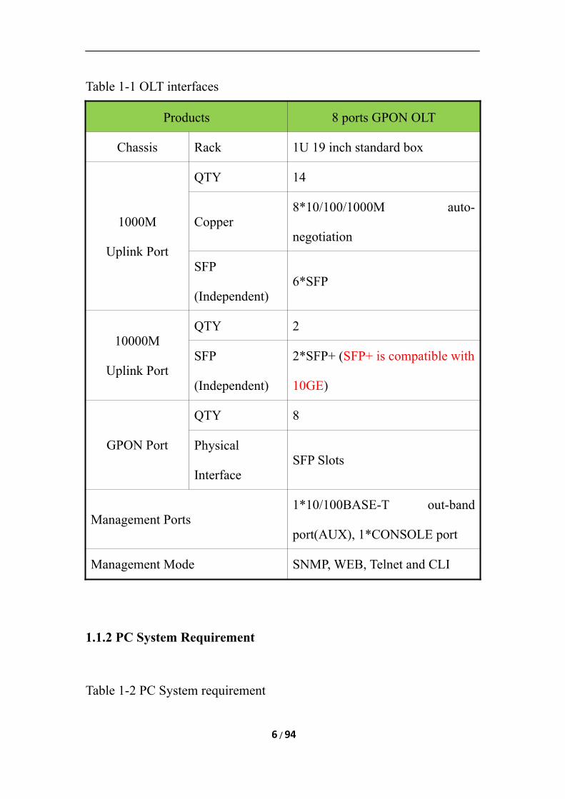
Table 1-1 OLT interfaces
Products 8 ports GPON OLT
Chassis Rack 1U 19 inch standard box
1000M
Uplink Port
QTY 14
Copper8*10/100/1000M auto-
negotiation
SFP
(Independent)6*SFP
10000M
Uplink Port
QTY 2
SFP
(Independent)
2*SFP+ (SFP+ is compatible with
10GE)
GPON Port
QTY 8
Physical
InterfaceSFP Slots
Management Ports1*10/100BASE-T out-band
port(AUX), 1*CONSOLE port
Management Mode SNMP, WEB, Telnet and CLI
1.1.2 PC System Requirement
Table 1-2 PC System requirement
6 / 94
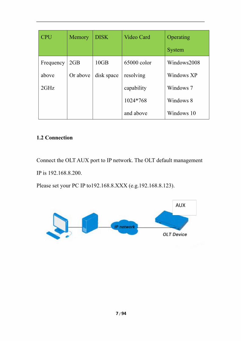
CPU Memory DISK Video Card Operating
System
Frequency
above
2GHz
2GB
Or above
10GB
disk space
65000 color
resolving
capability
1024*768
and above
Windows2008
Windows XP
Windows 7
Windows 8
Windows 10
1.2 Connection
Connect the OLT AUX port to IP network. The OLT default management
IP is 192.168.8.200.
Please set your PC IP to192.168.8.XXX (e.g.192.168.8.123).
7 / 94
AUX
Chapter 2 OLT Information
2.1 Login
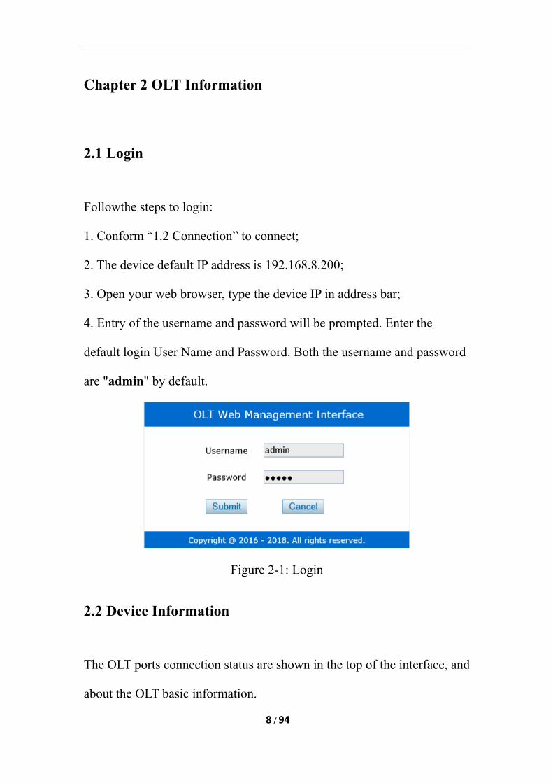
Followthe steps to login:
1. Conform “1.2 Connection” to connect;
2. The device default IP address is 192.168.8.200;
3. Open your web browser, type the device IP in address bar;
4. Entry of the username and password will be prompted. Enter the
default login User Name and Password. Both the username and password
are "admin" by default.
Figure 2-1: Login
2.2 Device Information
The OLT ports connection status are shown in the top of the interface, and
about the OLT basic information.
8 / 94
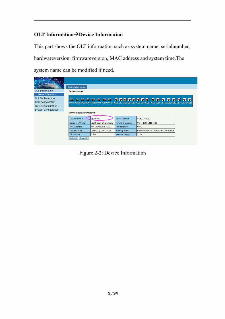
OLT InformationDevice Information
This part shows the OLT information such as system name, serialnumber,
hardwareversion, firmwareversion, MAC address and system time.The
system name can be modified if need.
Figure 2-2: Device Information
9 / 94
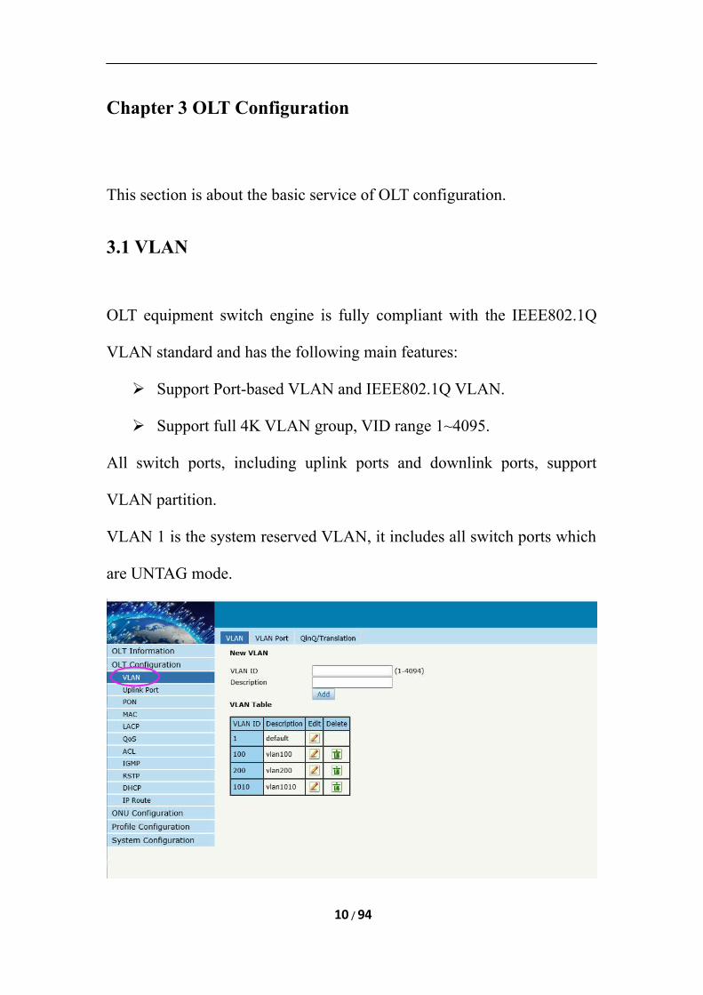
Chapter 3 OLT Configuration
This section is about the basic service of OLT configuration.
3.1 VLAN
OLT equipment switch engine is fully compliant with the IEEE802.1Q
VLAN standard and has the following main features:
Support Port-based VLAN and IEEE802.1Q VLAN.
Support full 4K VLAN group, VID range 1~4095.
All switch ports, including uplink ports and downlink ports, support
VLAN partition.
VLAN 1 is the system reserved VLAN, it includes all switch ports which
are UNTAG mode.
10 / 94
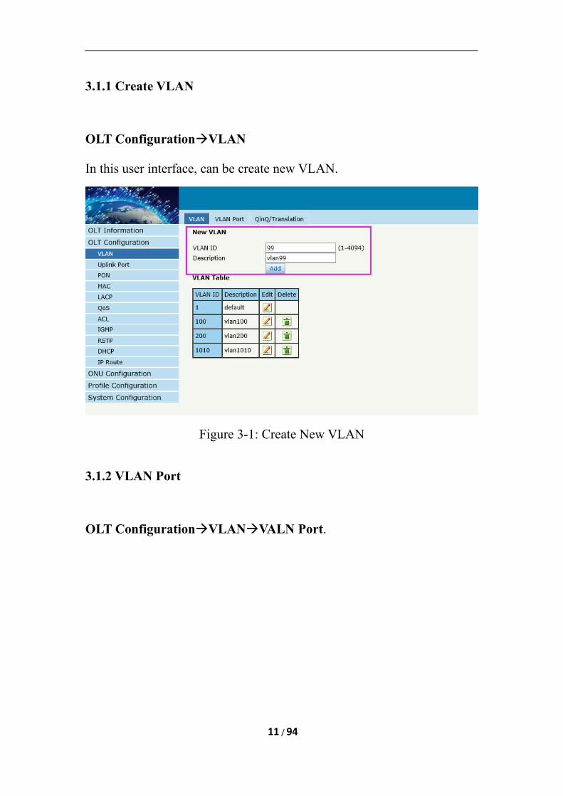
3.1.1 Create VLAN
OLT ConfigurationVLAN
In this user interface, can be create new VLAN.
Figure 3-1: Create New VLAN
3.1.2 VLAN Port
OLT ConfigurationVLANVALN Port.
11 / 94
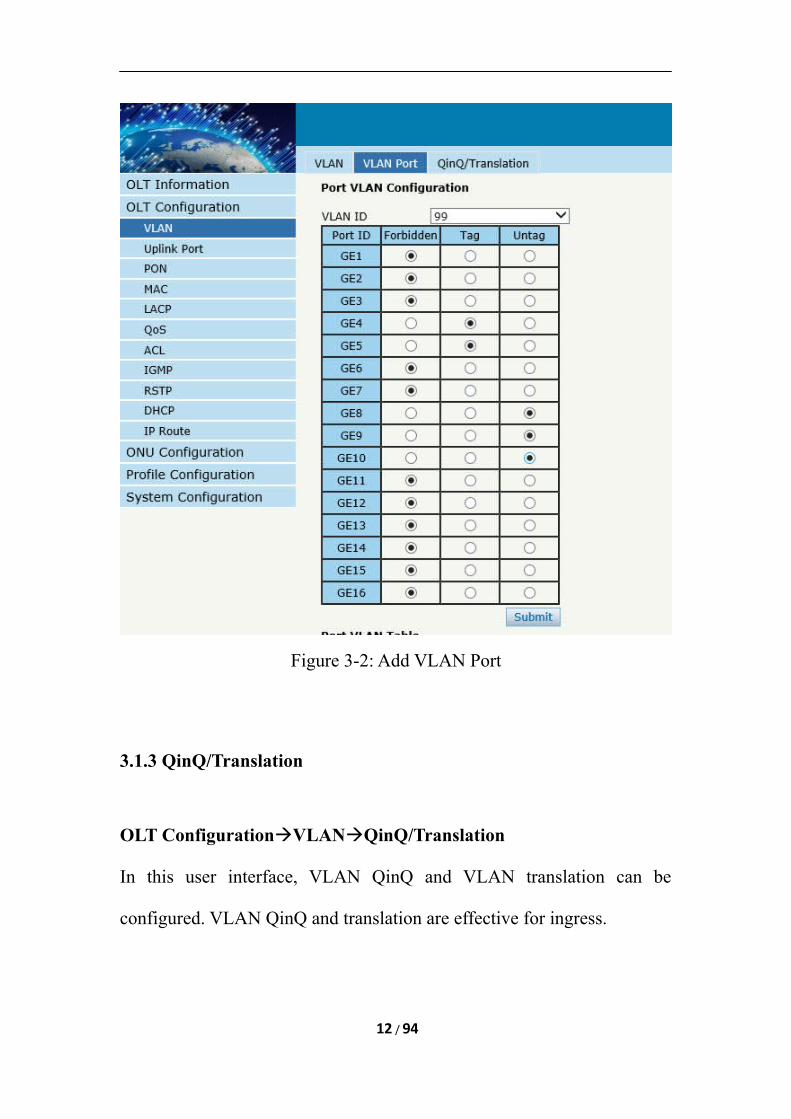
Figure 3-2: Add VLAN Port
3.1.3 QinQ/Translation
OLT ConfigurationVLANQinQ/Translation
In this user interface, VLAN QinQ and VLAN translation can be
configured. VLAN QinQ and translation are effective for ingress.
12 / 94
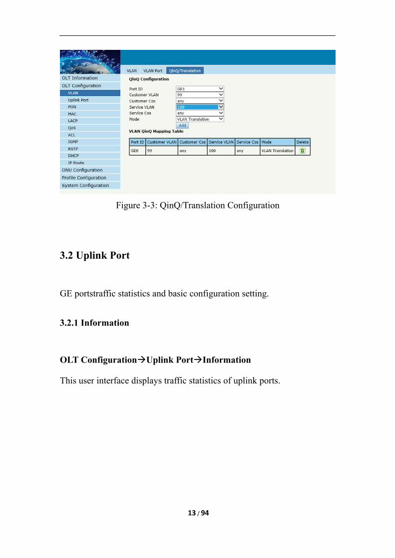
Figure 3-3: QinQ/Translation Configuration
3.2 Uplink Port
GE portstraffic statistics and basic configuration setting.
3.2.1 Information
OLT ConfigurationUplink PortInformation
This user interface displays traffic statistics of uplink ports.
13 / 94
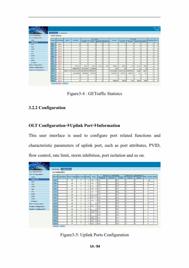
Figure3-4 : GETraffic Statistcs
3.2.2 Configuration
OLT ConfigurationUplink PortInformation
This user interface is used to configure port related functions and
characteristic parameters of uplink port, such as port attributes, PVID,
flow control, rate limit, storm inhibition, port isolation and so on.
Figure3-5: Uplink Ports Configuration
14 / 94
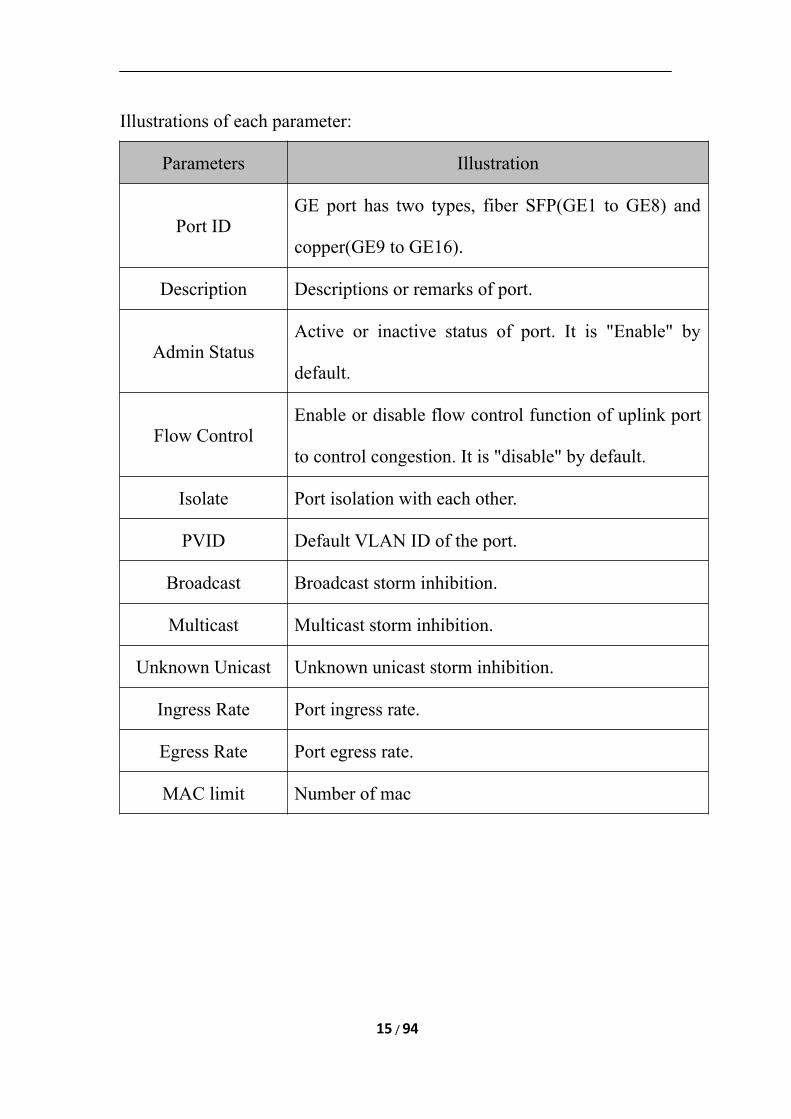
Illustrations of each parameter:
Parameters Illustration
Port IDGE port has two types, fiber SFP(GE1 to GE8) and
copper(GE9 to GE16).
Description Descriptions or remarks of port.
Admin StatusActive or inactive status of port. It is "Enable" by
default.
Flow ControlEnable or disable flow control function of uplink port
to control congestion. It is "disable" by default.
Isolate Port isolation with each other.
PVID Default VLAN ID of the port.
Broadcast Broadcast storm inhibition.
Multicast Multicast storm inhibition.
Unknown Unicast Unknown unicast storm inhibition.
Ingress Rate Port ingress rate.
Egress Rate Port egress rate.
MAC limit Number of mac
15 / 94
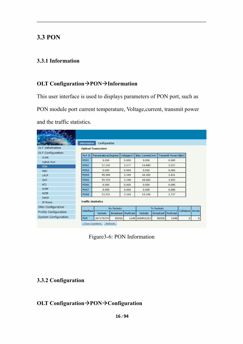
3.3 PON
3.3.1 Information
OLT ConfigurationPONInformation
This user interface is used to displays parameters of PON port, such as
PON module port current temperature, Voltage,current, transmit power
and the traffic statistics.
Figure3-6: PON Information
3.3.2 Configuration
OLT ConfigurationPONConfiguration
16 / 94
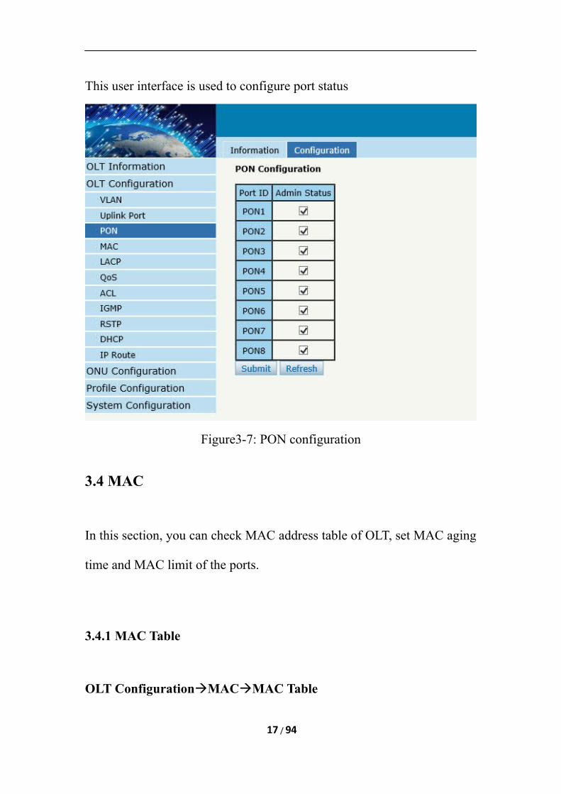
This user interface is used to configure port status
Figure3-7: PON configuration
3.4 MAC
In this section, you can check MAC address table of OLT, set MAC aging
time and MAC limit of the ports.
3.4.1 MAC Table
OLT ConfigurationMACMAC Table
17 / 94
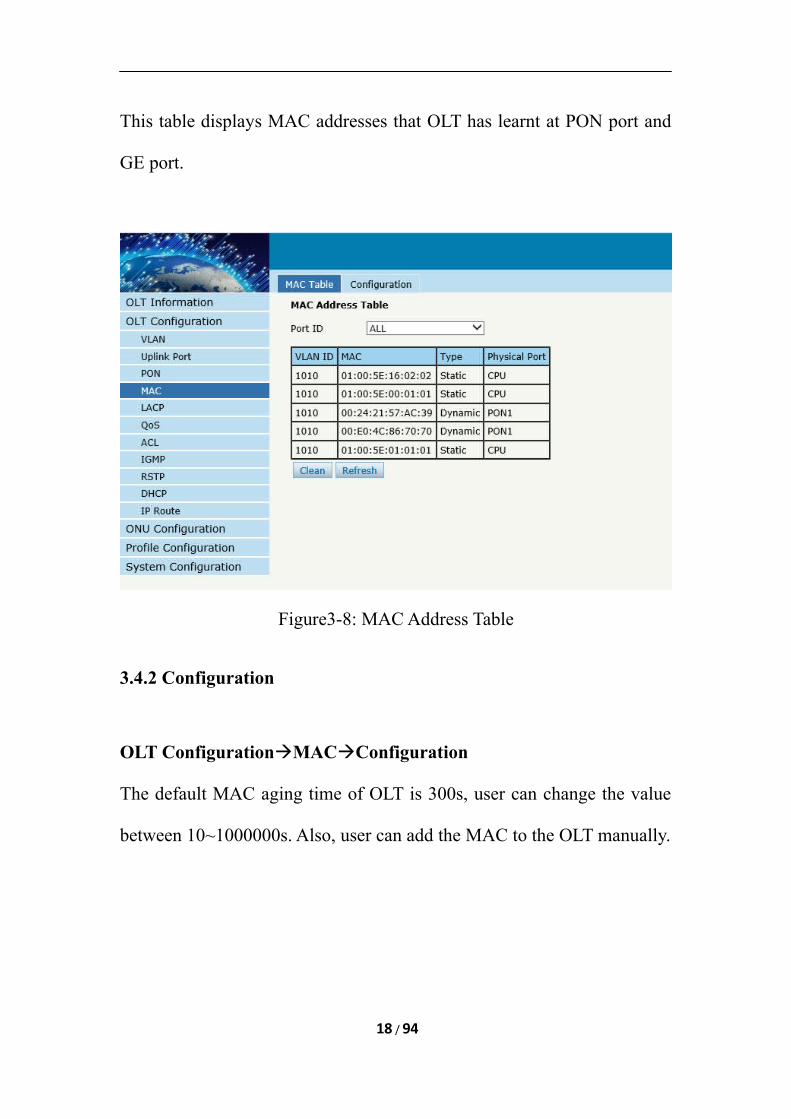
This table displays MAC addresses that OLT has learnt at PON port and
GE port.
Figure3-8: MAC Address Table
3.4.2 Configuration
OLT ConfigurationMACConfiguration
The default MAC aging time of OLT is 300s, user can change the value
between 10~1000000s. Also, user can add the MAC to the OLT manually.
18 / 94
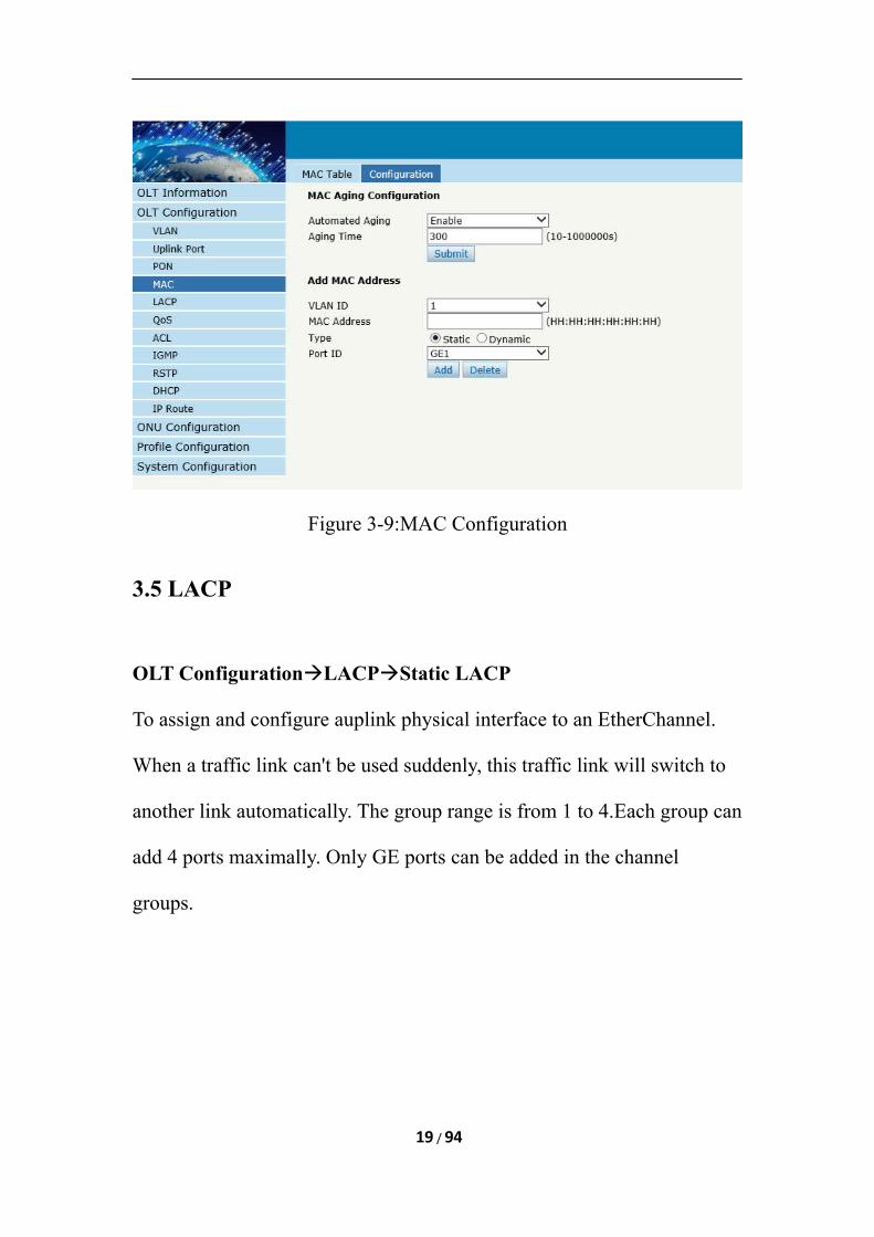
Figure 3-9:MAC Configuration
3.5 LACP
OLT ConfigurationLACPStatic LACP
To assign and configure auplink physical interface to an EtherChannel.
When a traffic link can't be used suddenly, this traffic link will switch to
another link automatically. The group range is from 1 to 4.Each group can
add 4 ports maximally. Only GE ports can be added in the channel
groups.
19 / 94
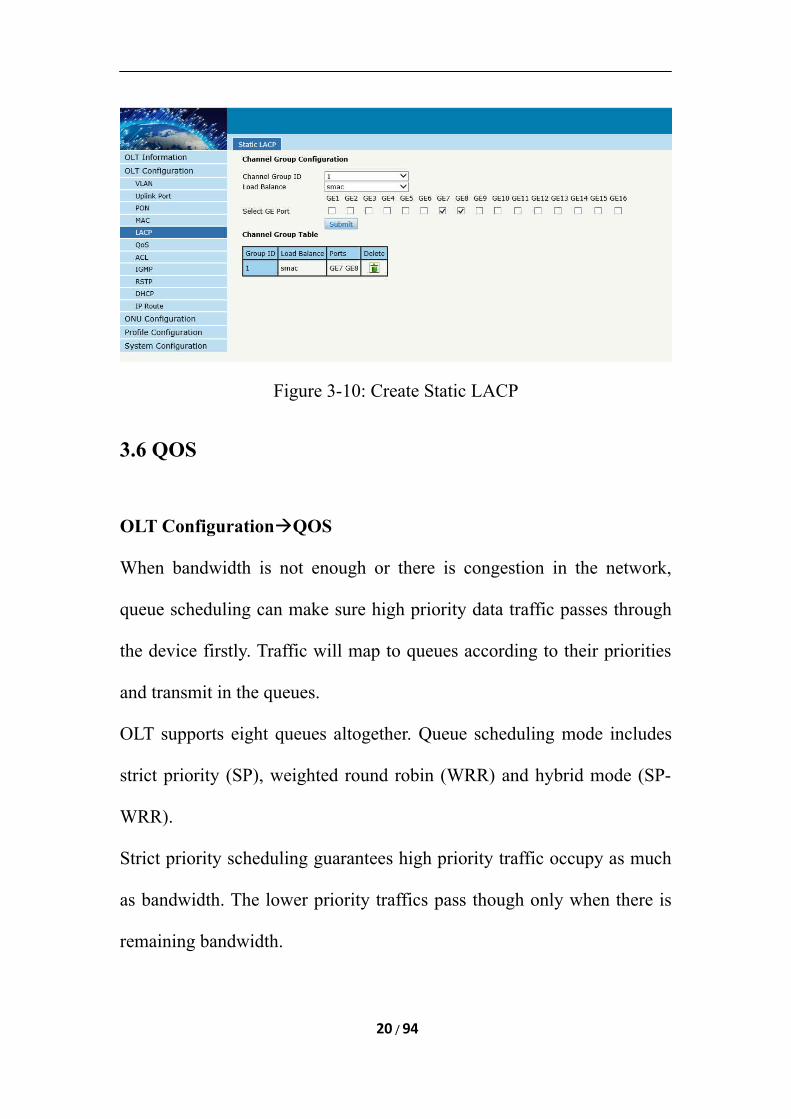
Figure 3-10: Create Static LACP
3.6 QOS
OLT ConfigurationQOS
When bandwidth is not enough or there is congestion in the network,
queue scheduling can make sure high priority data traffic passes through
the device firstly. Traffic will map to queues according to their priorities
and transmit in the queues.
OLT supports eight queues altogether. Queue scheduling mode includes
strict priority (SP), weighted round robin (WRR) and hybrid mode (SP-
WRR).
Strict priority scheduling guarantees high priority traffic occupy as much
as bandwidth. The lower priority traffics pass though only when there is
remaining bandwidth.
20 / 94
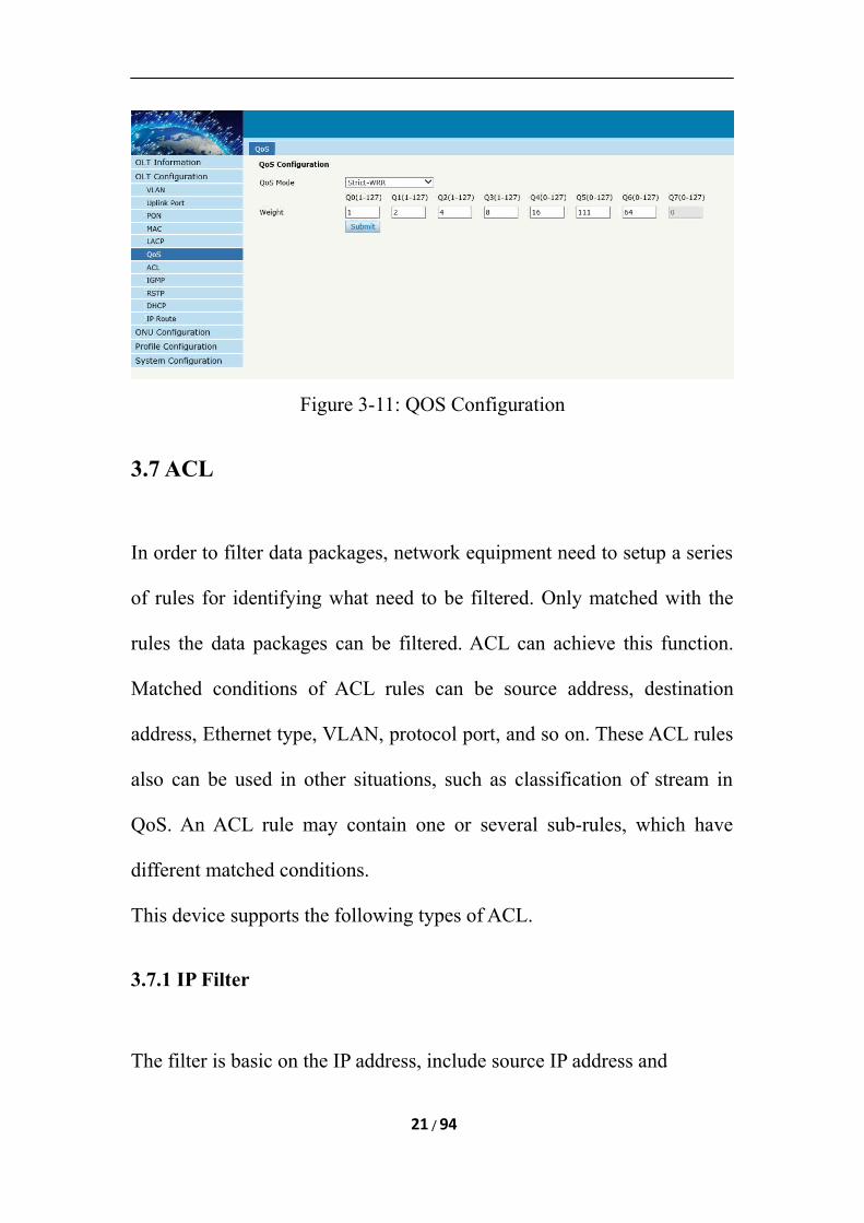
Figure 3-11: QOS Configuration
3.7 ACL
In order to filter data packages, network equipment need to setup a series
of rules for identifying what need to be filtered. Only matched with the
rules the data packages can be filtered. ACL can achieve this function.
Matched conditions of ACL rules can be source address, destination
address, Ethernet type, VLAN, protocol port, and so on. These ACL rules
also can be used in other situations, such as classification of stream in
QoS. An ACL rule may contain one or several sub-rules, which have
different matched conditions.
This device supports the following types of ACL.
3.7.1 IP Filter
The filter is basic on the IP address, include source IP address and
21 / 94
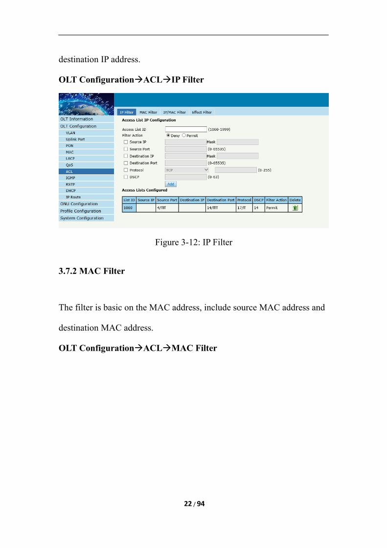
destination IP address.
OLT ConfigurationACLIP Filter
Figure 3-12: IP Filter
3.7.2 MAC Filter
The filter is basic on the MAC address, include source MAC address and
destination MAC address.
OLT ConfigurationACLMAC Filter
22 / 94
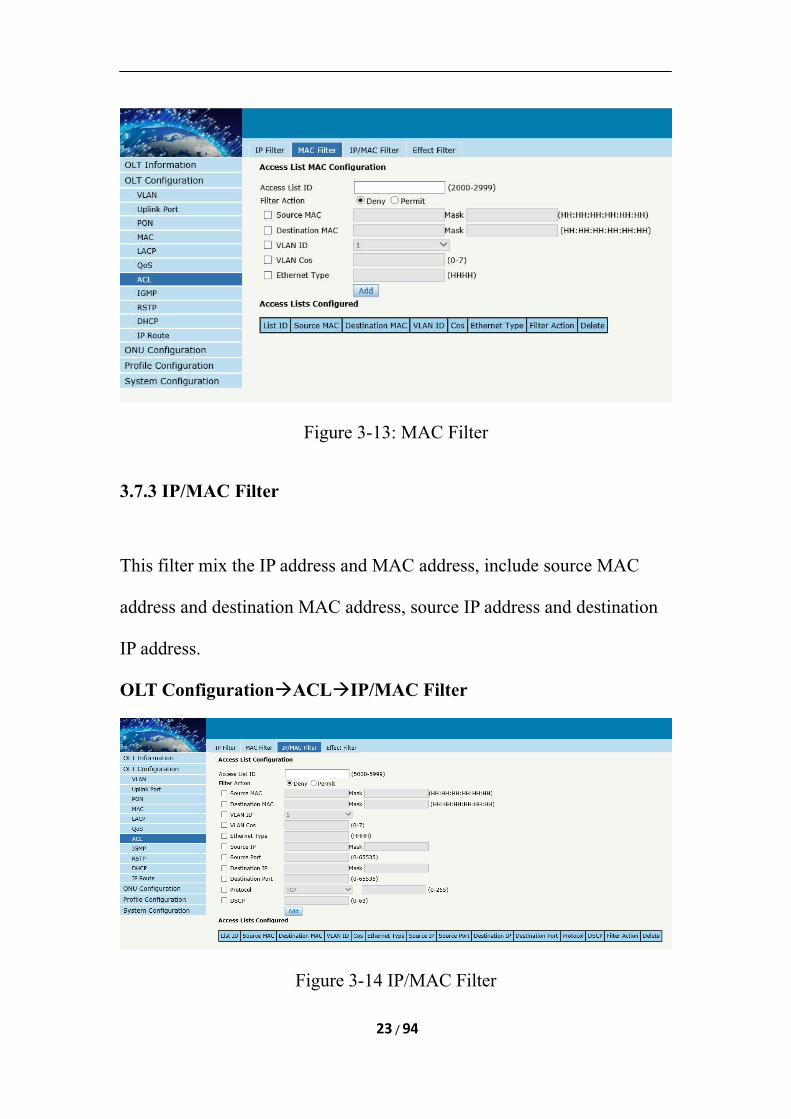
Figure 3-13: MAC Filter
3.7.3 IP/MAC Filter
This filter mix the IP address and MAC address, include source MAC
address and destination MAC address, source IP address and destination
IP address.
OLT ConfigurationACLIP/MAC Filter
Figure 3-14 IP/MAC Filter
23 / 94
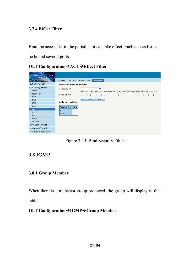
3.7.4 Effect Filter
Bind the access list to the portsthen it can take effect. Each access list can
be bound several ports.
OLT ConfigurationACLEffect Filter
Figure 3-15: Bind Security Filter
3.8 IGMP
3.8.1 Group Member
When there is a multicast group produced, the group will display in this
table.
OLT ConfigurationIGMPGroup Member
24 / 94
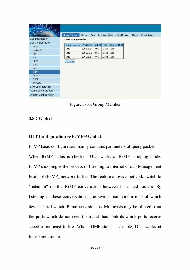
Figure 3-16: Group Member
3.8.2 Global
OLT Configuration IGMPGlobal.
IGMP basic configuration mainly contains parameters of query packet.
When IGMP status is checked, OLT works at IGMP snooping mode.
IGMP snooping is the process of listening to Internet Group Management
Protocol (IGMP) network traffic. The feature allows a network switch to
"listen in" on the IGMP conversation between hosts and routers. By
listening to these conversations, the switch maintains a map of which
devices need which IP multicast streams. Multicasts may be filtered from
the ports which do not need them and thus controls which ports receive
specific multicast traffic. When IGMP status is disable, OLT works at
transparent mode.
25 / 94
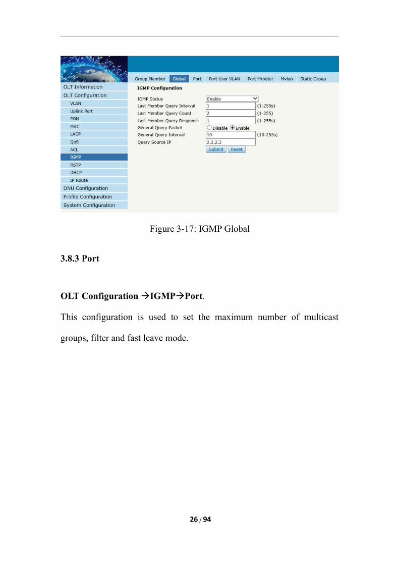
Figure 3-17: IGMP Global
3.8.3 Port
OLT Configuration IGMPPort.
This configuration is used to set the maximum number of multicast
groups, filter and fast leave mode.
26 / 94
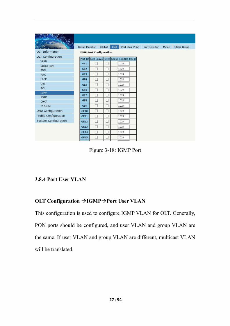
Figure 3-18: IGMP Port
3.8.4 Port User VLAN
OLT Configuration IGMPPort User VLAN
This configuration is used to configure IGMP VLAN for OLT. Generally,
PON ports should be configured, and user VLAN and group VLAN are
the same. If user VLAN and group VLAN are different, multicast VLAN
will be translated.
27 / 94
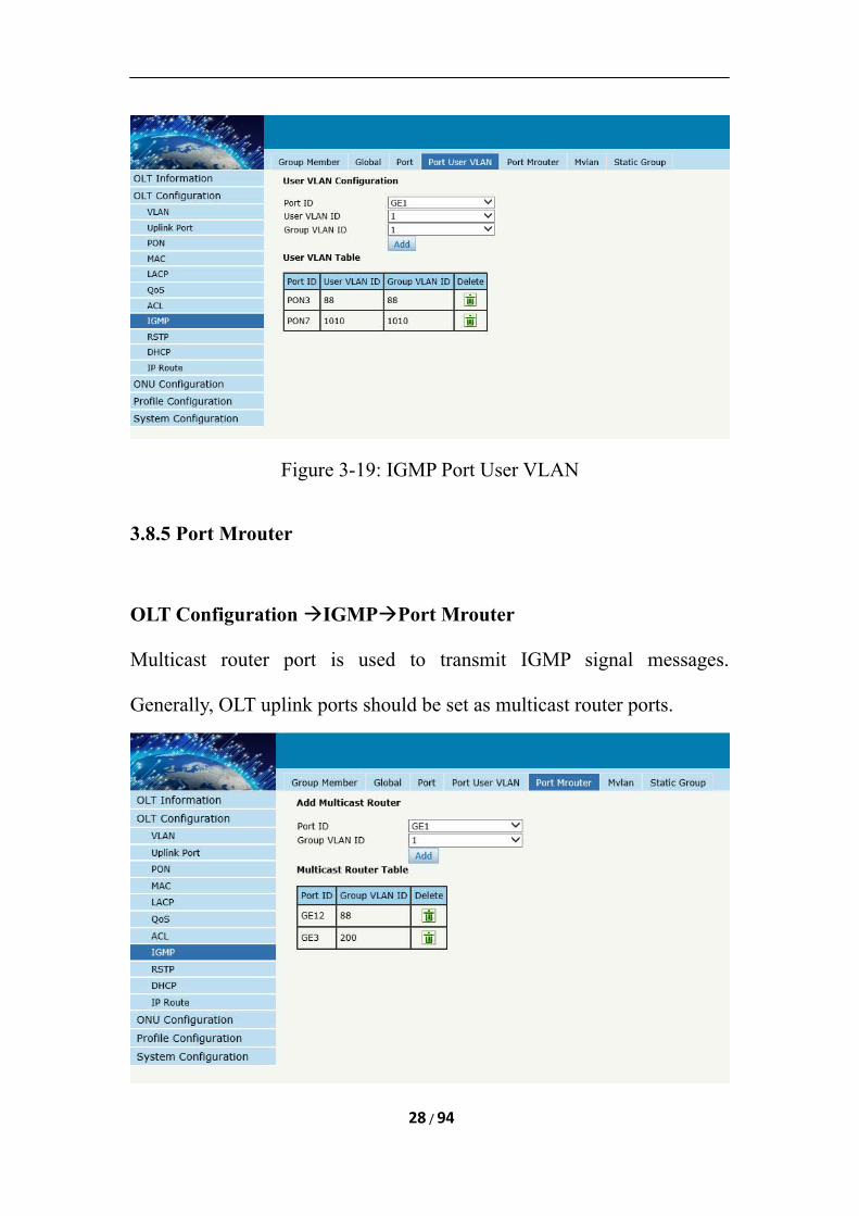
Figure 3-19: IGMP Port User VLAN
3.8.5 Port Mrouter
OLT Configuration IGMPPort Mrouter
Multicast router port is used to transmit IGMP signal messages.
Generally, OLT uplink ports should be set as multicast router ports.
28 / 94
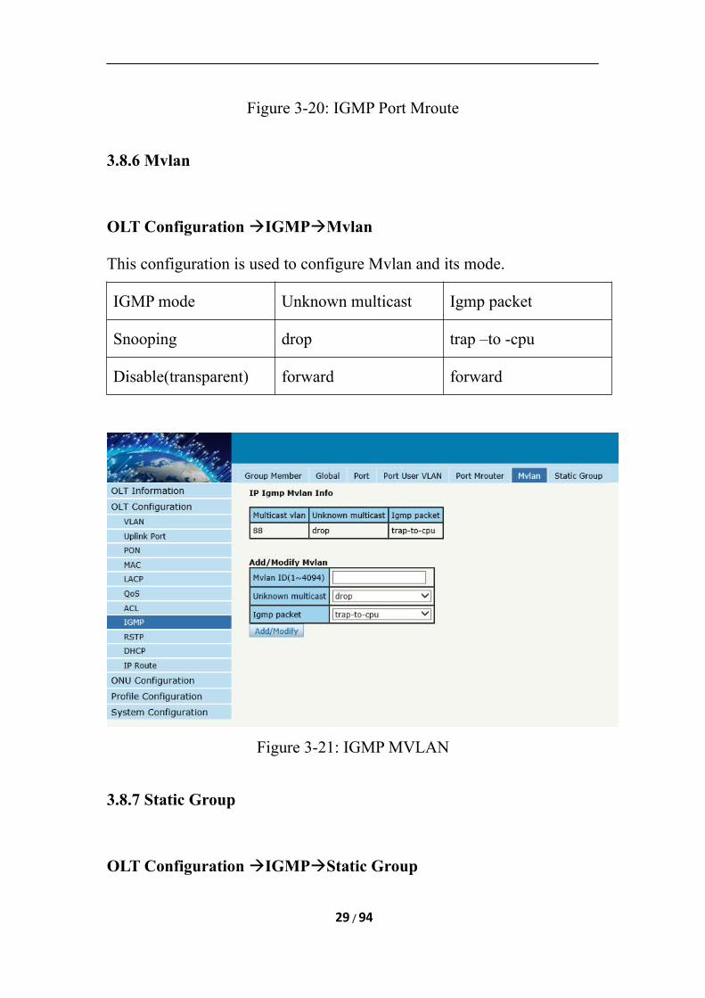
Figure 3-20: IGMP Port Mroute
3.8.6 Mvlan
OLT Configuration IGMPMvlan
This configuration is used to configure Mvlan and its mode.
IGMP mode Unknown multicast Igmp packet
Snooping drop trap –to -cpu
Disable(transparent) forward forward
Figure 3-21: IGMP MVLAN
3.8.7 Static Group
OLT Configuration IGMPStatic Group
29 / 94
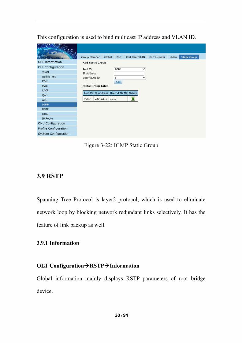
This configuration is used to bind multicast IP address and VLAN ID.
Figure 3-22: IGMP Static Group
3.9 RSTP
Spanning Tree Protocol is layer2 protocol, which is used to eliminate
network loop by blocking network redundant links selectively. It has the
feature of link backup as well.
3.9.1 Information
OLT ConfigurationRSTPInformation
Global information mainly displays RSTP parameters of root bridge
device.
30 / 94
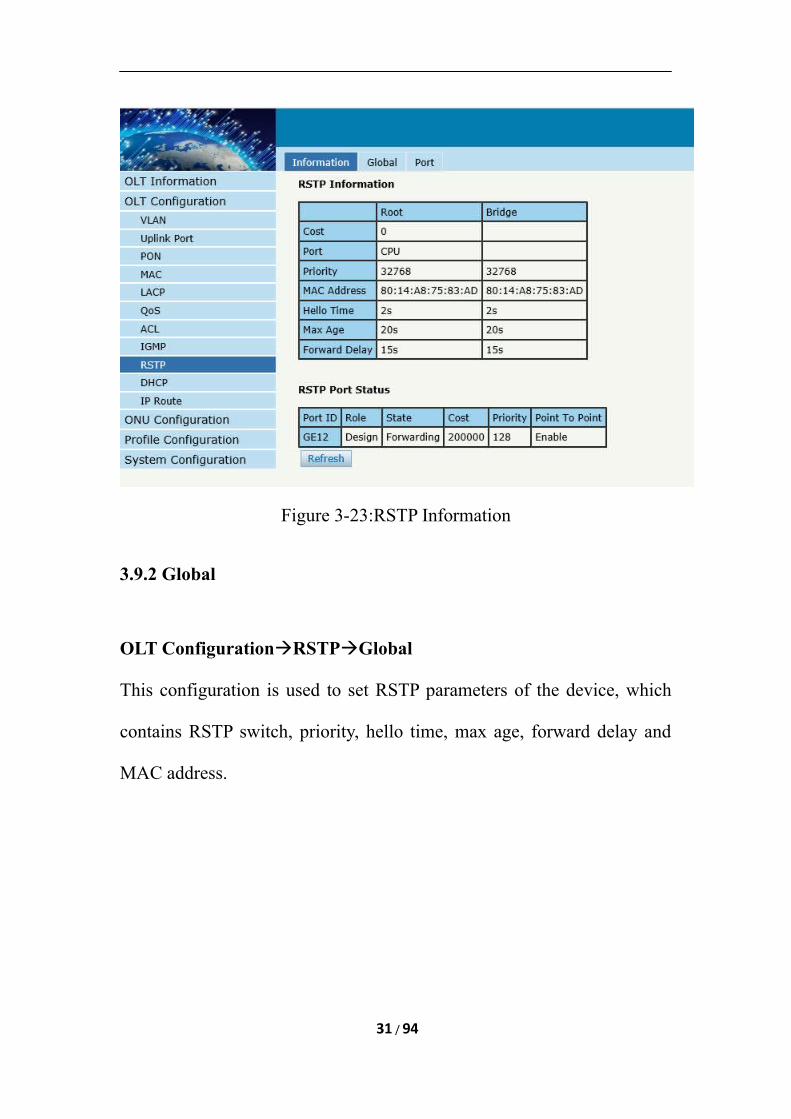
Figure 3-23:RSTP Information
3.9.2 Global
OLT ConfigurationRSTPGlobal
This configuration is used to set RSTP parameters of the device, which
contains RSTP switch, priority, hello time, max age, forward delay and
MAC address.
31 / 94
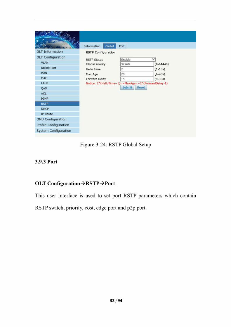
Figure 3-24: RSTP Global Setup
3.9.3 Port
OLT ConfigurationRSTPPort .
This user interface is used to set port RSTP parameters which contain
RSTP switch, priority, cost, edge port and p2p port.
32 / 94
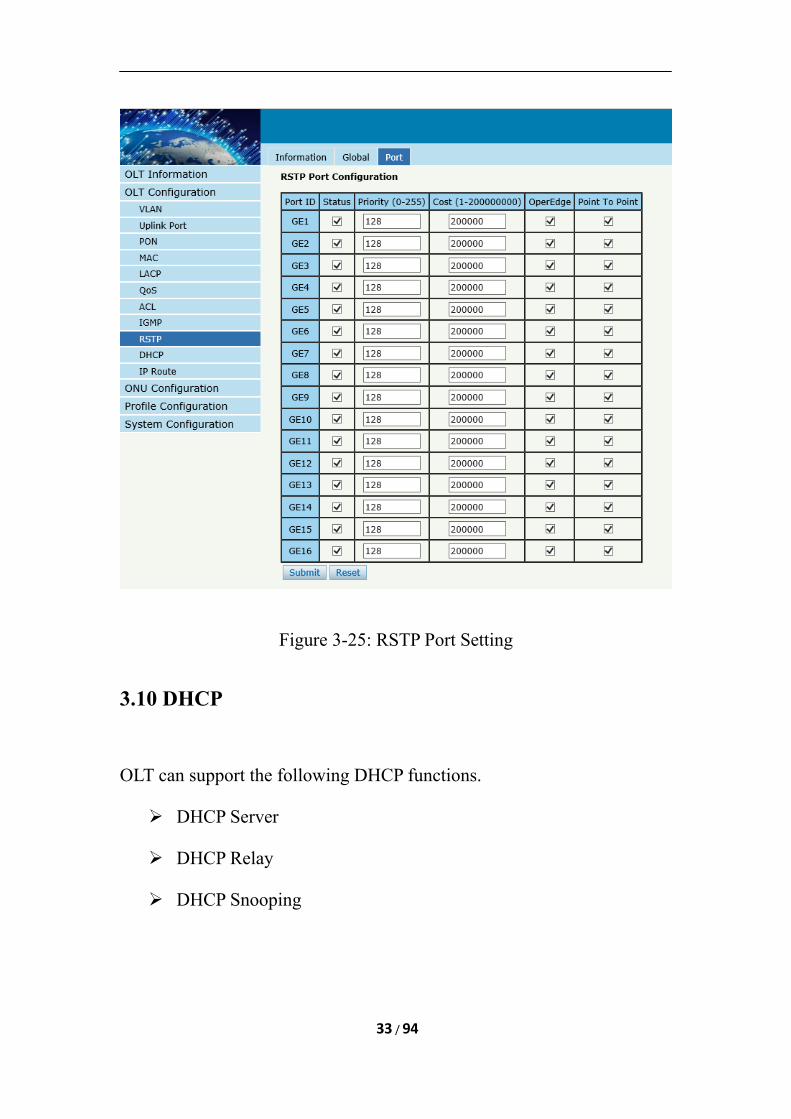
Figure 3-25: RSTP Port Setting
3.10 DHCP
OLT can support the following DHCP functions.
DHCP Server
DHCP Relay
DHCP Snooping
33 / 94
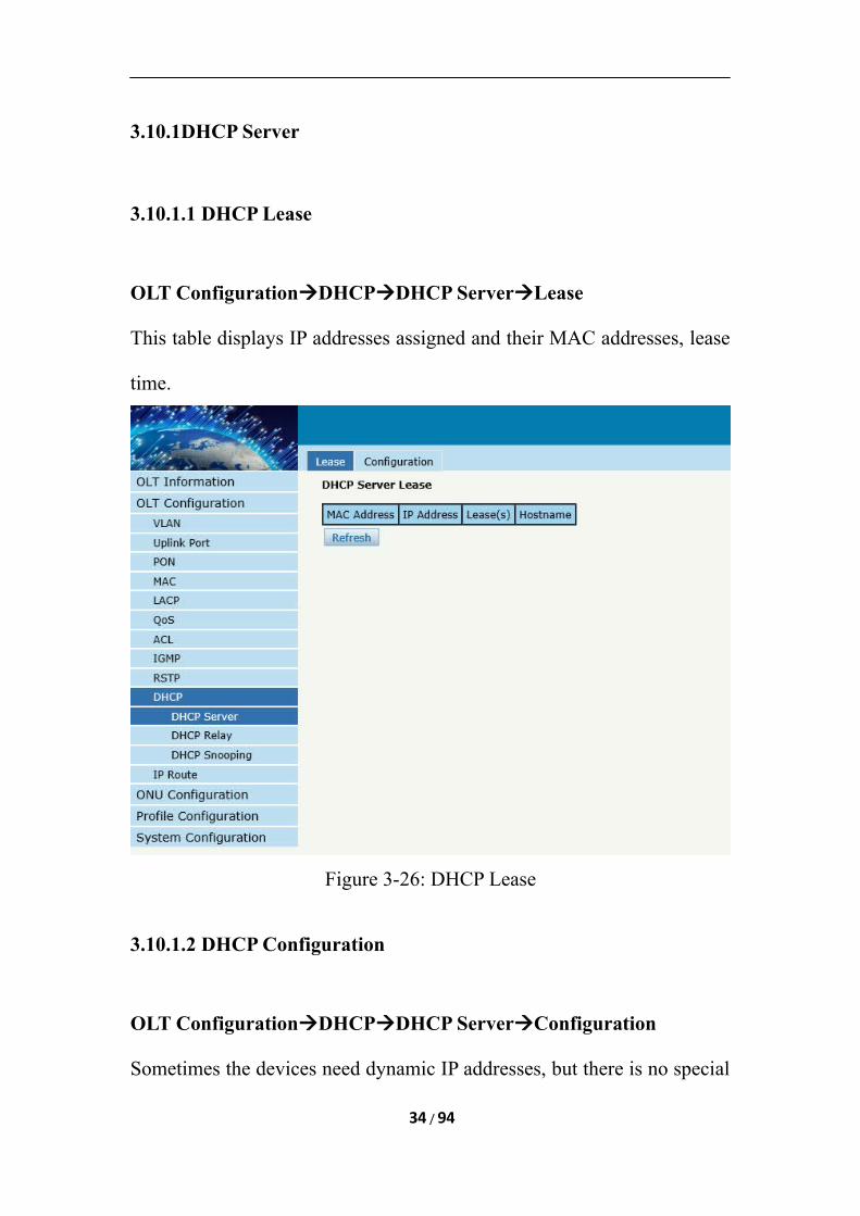
3.10.1DHCP Server
3.10.1.1 DHCP Lease
OLT ConfigurationDHCPDHCP ServerLease
This table displays IP addresses assigned and their MAC addresses, lease
time.
Figure 3-26: DHCP Lease
3.10.1.2 DHCP Configuration
OLT ConfigurationDHCPDHCP ServerConfiguration
Sometimes the devices need dynamic IP addresses, but there is no special
34 / 94
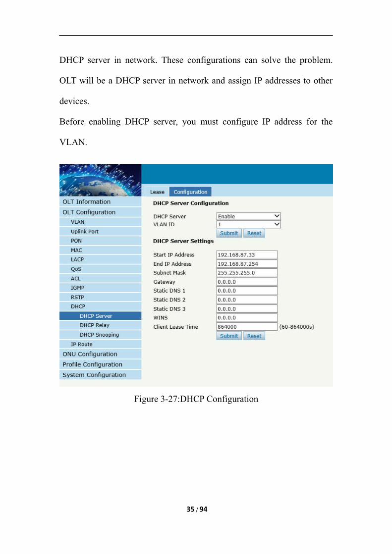
DHCP server in network. These configurations can solve the problem.
OLT will be a DHCP server in network and assign IP addresses to other
devices.
Before enabling DHCP server, you must configure IP address for the
VLAN.
Figure 3-27:DHCP Configuration
35 / 94
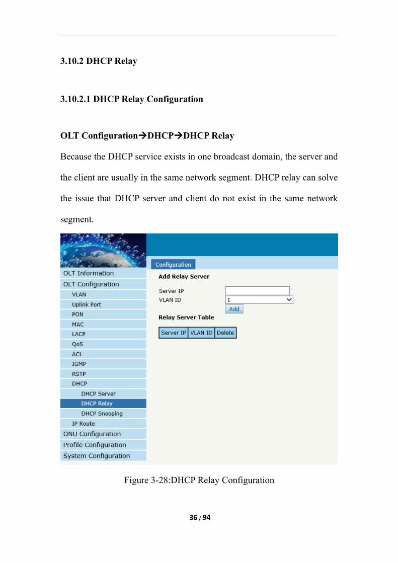
3.10.2 DHCP Relay
3.10.2.1 DHCP Relay Configuration
OLT ConfigurationDHCPDHCP Relay
Because the DHCP service exists in one broadcast domain, the server and
the client are usually in the same network segment. DHCP relay can solve
the issue that DHCP server and client do not exist in the same network
segment.
Figure 3-28:DHCP Relay Configuration
36 / 94
3.10.3 DHCP Snooping
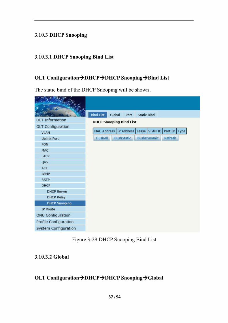
3.10.3.1 DHCP Snooping Bind List
OLT ConfigurationDHCPDHCP SnoopingBind List
The static bind of the DHCP Snooping will be shown ,
Figure 3-29:DHCP Snooping Bind List
3.10.3.2 Global
OLT ConfigurationDHCPDHCP SnoopingGlobal
37 / 94
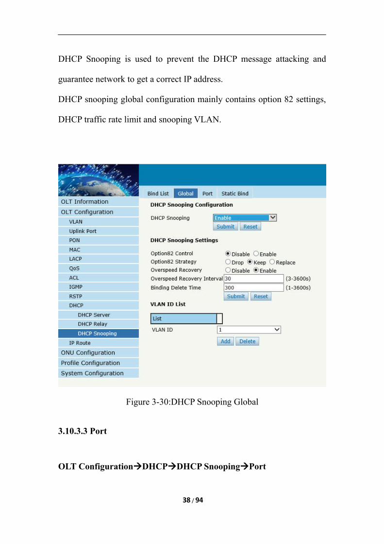
DHCP Snooping is used to prevent the DHCP message attacking and
guarantee network to get a correct IP address.
DHCP snooping global configuration mainly contains option 82 settings,
DHCP traffic rate limit and snooping VLAN.
Figure 3-30:DHCP Snooping Global
3.10.3.3 Port
OLT ConfigurationDHCPDHCP SnoopingPort
38 / 94
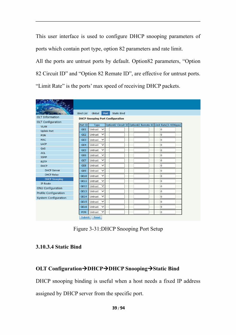
This user interface is used to configure DHCP snooping parameters of
ports which contain port type, option 82 parameters and rate limit.
All the ports are untrust ports by default. Option82 parameters, “Option
82 Circuit ID” and “Option 82 Remate ID”, are effective for untrust ports.
“Limit Rate” is the ports’ max speed of receiving DHCP packets.
Figure 3-31:DHCP Snooping Port Setup
3.10.3.4 Static Bind
OLT ConfigurationDHCPDHCP SnoopingStatic Bind
DHCP snooping binding is useful when a host needs a fixed IP address
assigned by DHCP server from the specific port.
39 / 94
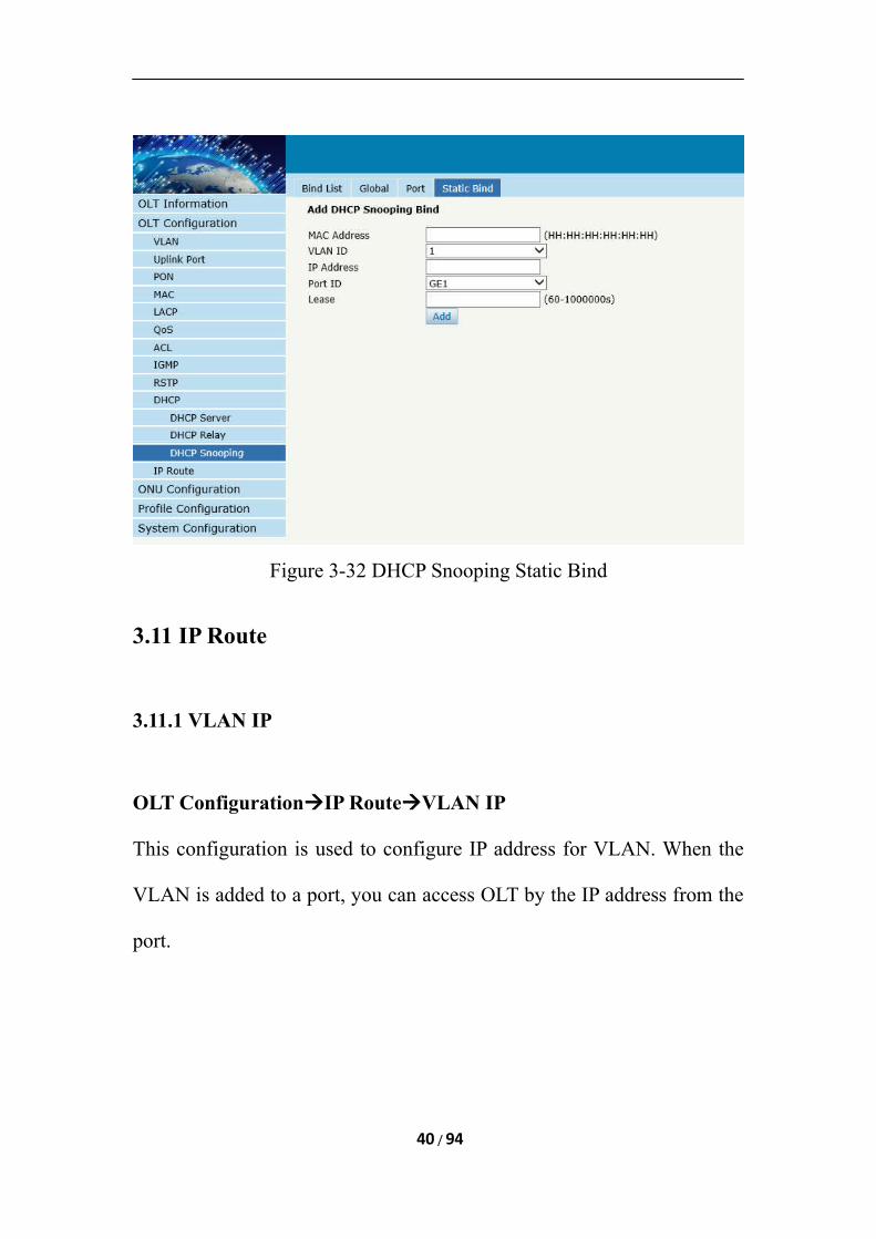
Figure 3-32 DHCP Snooping Static Bind
3.11 IP Route
3.11.1 VLAN IP
OLT ConfigurationIP RouteVLAN IP
This configuration is used to configure IP address for VLAN. When the
VLAN is added to a port, you can access OLT by the IP address from the
port.
40 / 94
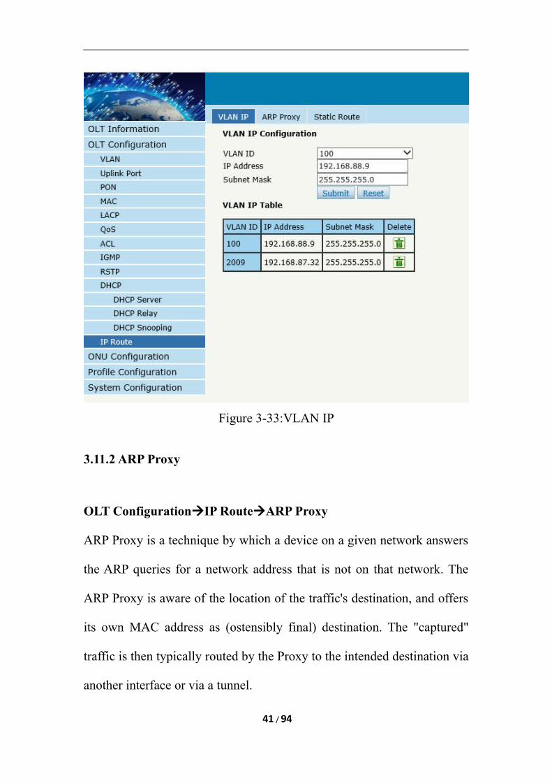
Figure 3-33:VLAN IP
3.11.2 ARP Proxy
OLT ConfigurationIP RouteARP Proxy
ARP Proxy is a technique by which a device on a given network answers
the ARP queries for a network address that is not on that network. The
ARP Proxy is aware of the location of the traffic's destination, and offers
its own MAC address as (ostensibly final) destination. The "captured"
traffic is then typically routed by the Proxy to the intended destination via
another interface or via a tunnel.
41 / 94
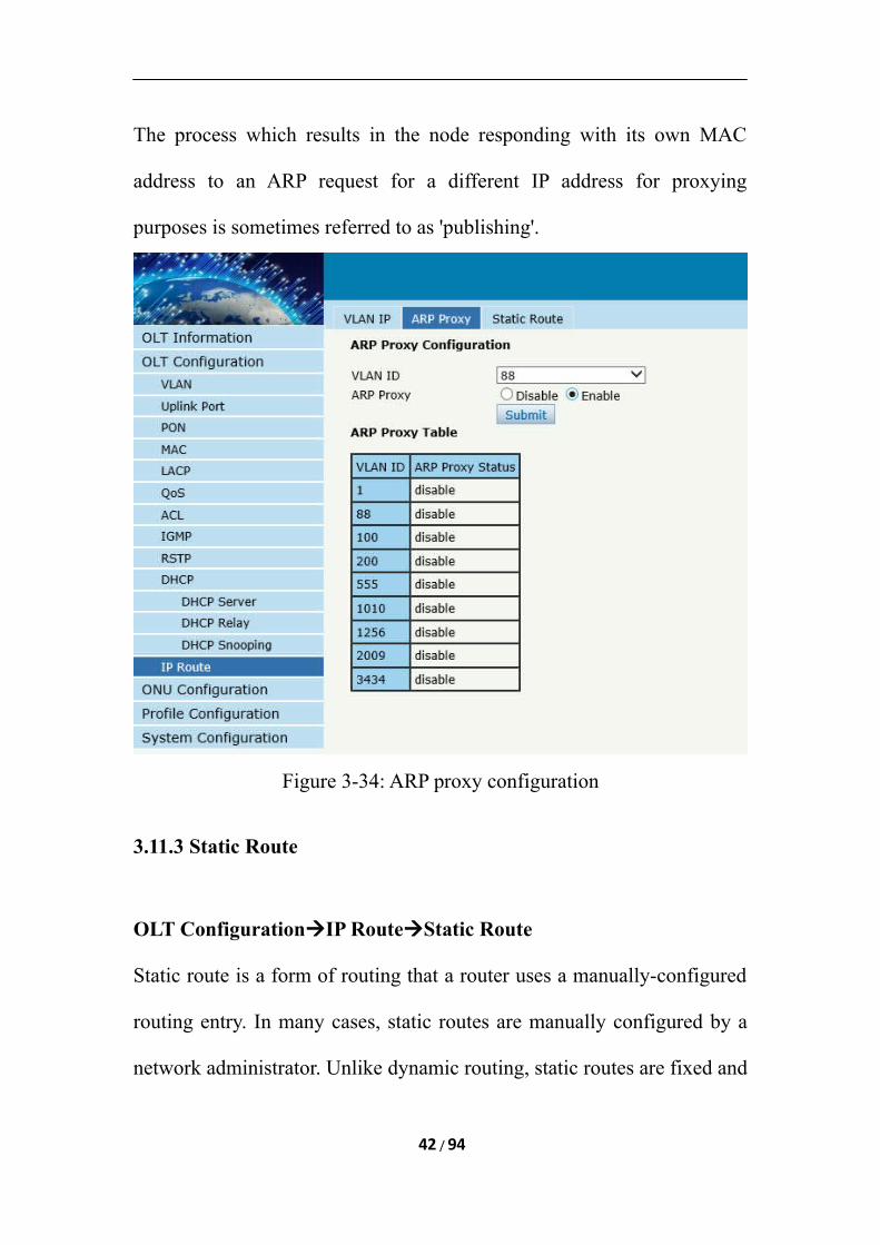
The process which results in the node responding with its own MAC
address to an ARP request for a different IP address for proxying
purposes is sometimes referred to as 'publishing'.
Figure 3-34: ARP proxy configuration
3.11.3 Static Route
OLT ConfigurationIP RouteStatic Route
Static route is a form of routing that a router uses a manually-configured
routing entry. In many cases, static routes are manually configured by a
network administrator. Unlike dynamic routing, static routes are fixed and
42 / 94
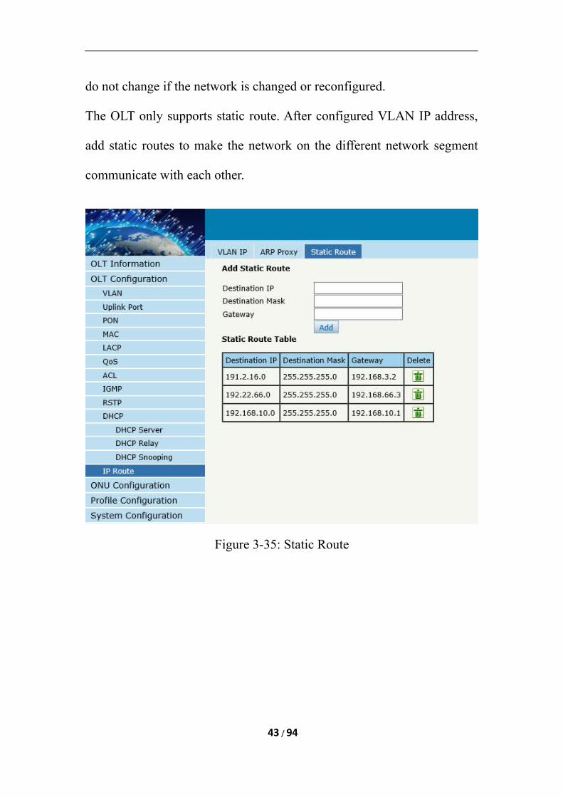
do not change if the network is changed or reconfigured.
The OLT only supports static route. After configured VLAN IP address,
add static routes to make the network on the different network segment
communicate with each other.
Figure 3-35: Static Route
43 / 94
Chapter 4 ONU Configuration
This chapter is about the ONU management by OLT.
4.1 ONU AuthList
4.1.1 ONU Status
ONU ConfigurationONU AuthListONU Status
Select PON port ID, all ONUs will be displayed in this interface.
You can check ONU Admin state、OMCC state and phase state.
If the phase state is working ,this ONU is registered successfully
44 / 94
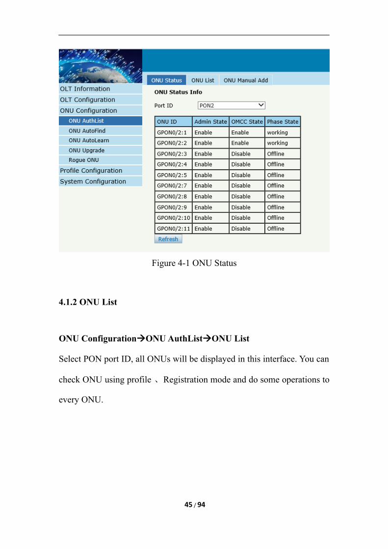
Figure 4-1 ONU Status
4.1.2 ONU List
ONU ConfigurationONU AuthListONU List
Select PON port ID, all ONUs will be displayed in this interface. You can
check ONU using profile 、Registration mode and do some operations to
every ONU.
45 / 94
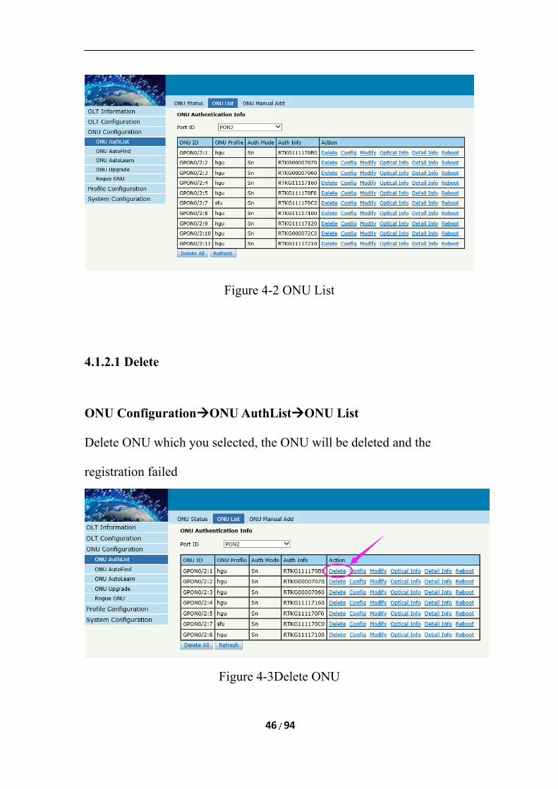
Figure 4-2 ONU List
4.1.2.1 Delete
ONU ConfigurationONU AuthListONU List
Delete ONU which you selected, the ONU will be deleted and the
registration failed
Figure 4-3Delete ONU
46 / 94
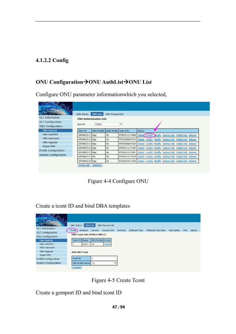
4.1.2.2 Config
ONU ConfigurationONU AuthListONU List
Configure ONU parameter informationwhich you selected,
Figure 4-4 Configure ONU
Create a tcont ID and bind DBA templates
Figure 4-5 Create Tcont
Create a gemport ID and bind tcont ID
47 / 94
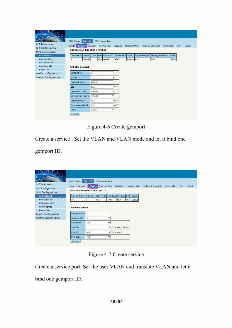
Figure 4-6 Create gemport
Create a service , Set the VLAN and VLAN mode and let it bind one
gemport ID.
Figure 4-7 Create service
Create a service port, Set the user VLAN and translate VLAN and let it
bind one gemport ID.
48 / 94
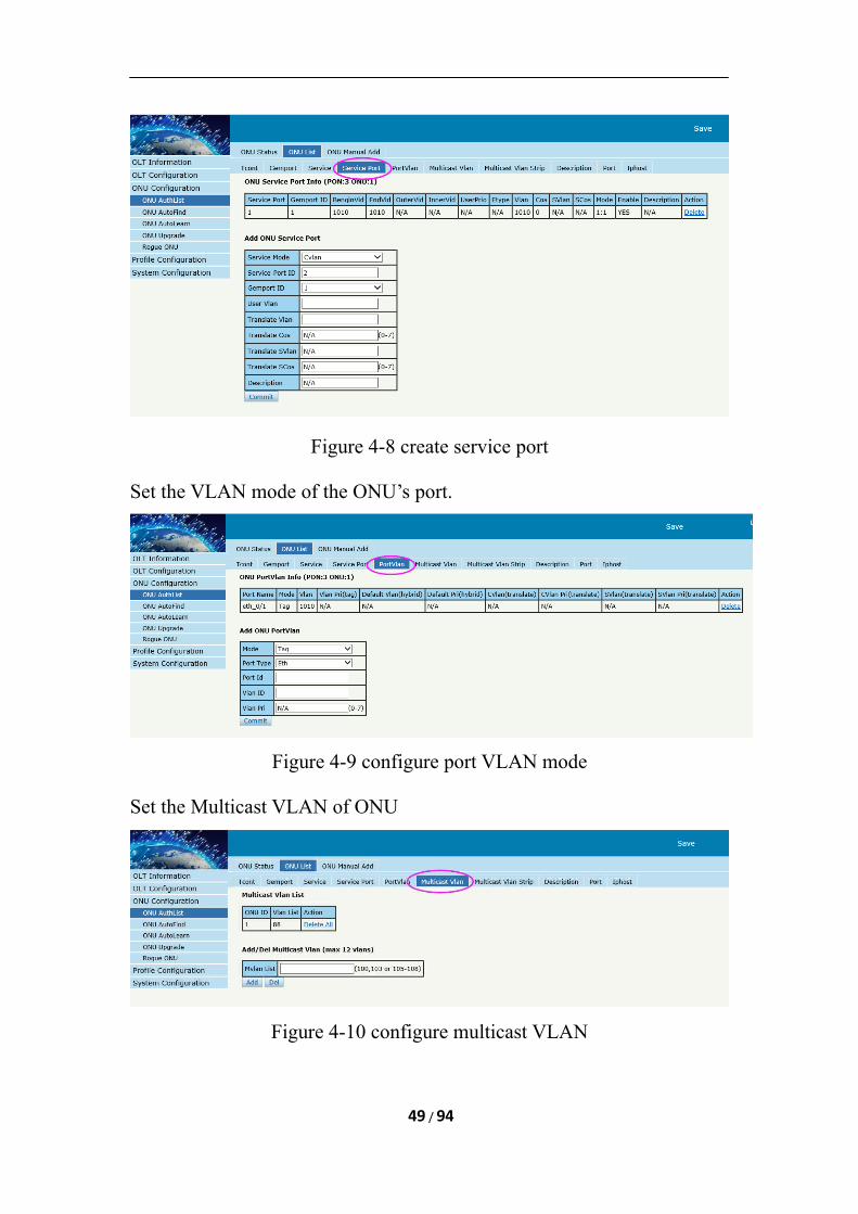
Figure 4-8 create service port
Set the VLAN mode of the ONU’s port.
Figure 4-9 configure port VLAN mode
Set the Multicast VLAN of ONU
Figure 4-10 configure multicast VLAN
49 / 94
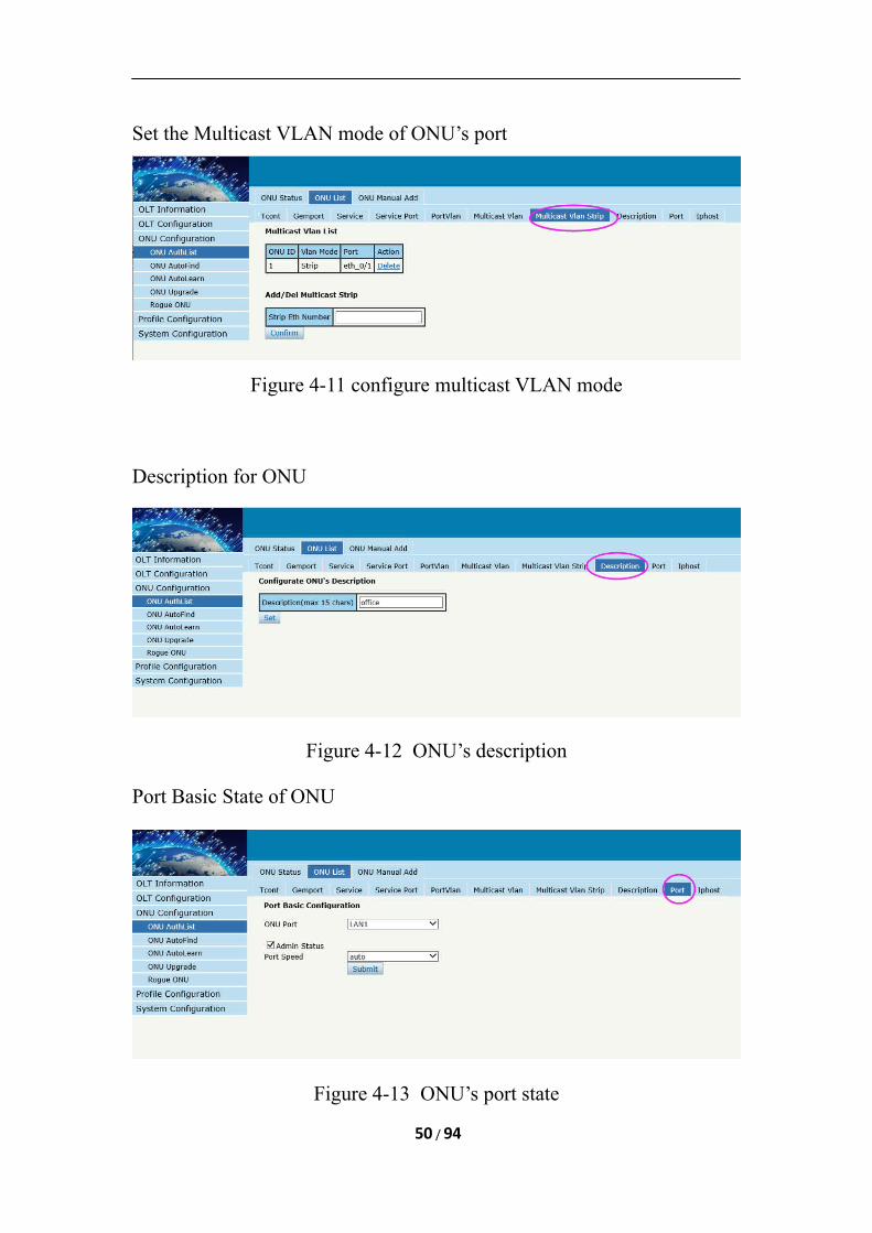
Set the Multicast VLAN mode of ONU’s port
Figure 4-11 configure multicast VLAN mode
Description for ONU
Figure 4-12 ONU’s description
Port Basic State of ONU
Figure 4-13 ONU’s port state
50 / 94
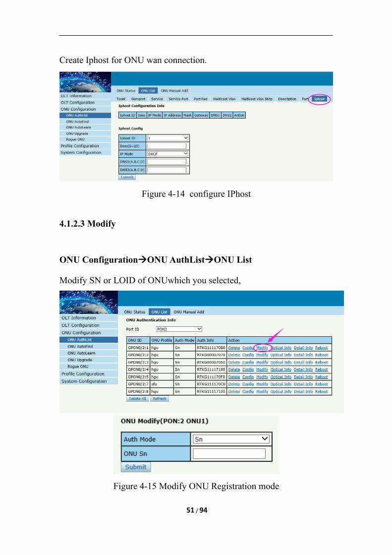
Create Iphost for ONU wan connection.
Figure 4-14 configure IPhost
4.1.2.3 Modify
ONU ConfigurationONU AuthListONU List
Modify SN or LOID of ONUwhich you selected,
Figure 4-15 Modify ONU Registration mode
51 / 94
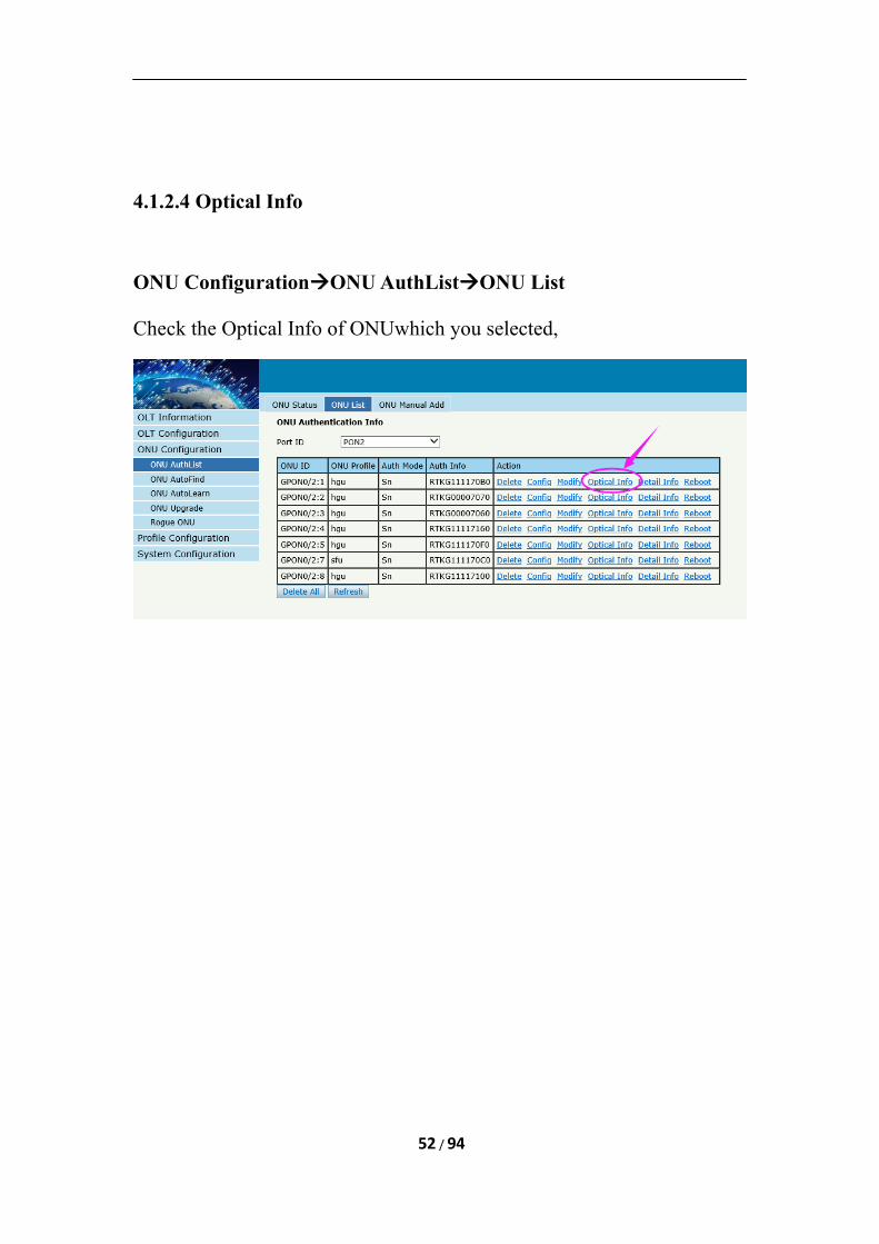
4.1.2.4 Optical Info
ONU ConfigurationONU AuthListONU List
Check the Optical Info of ONUwhich you selected,
52 / 94
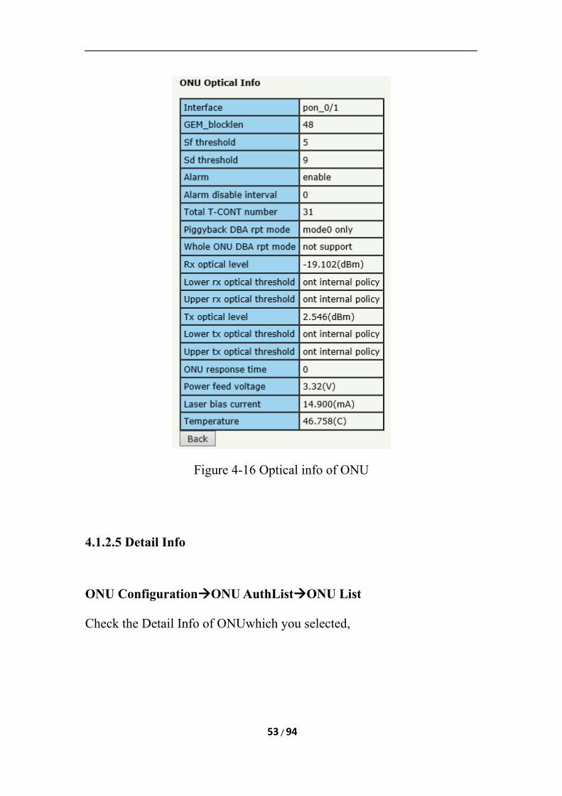
Figure 4-16 Optical info of ONU
4.1.2.5 Detail Info
ONU ConfigurationONU AuthListONU List
Check the Detail Info of ONUwhich you selected,
53 / 94
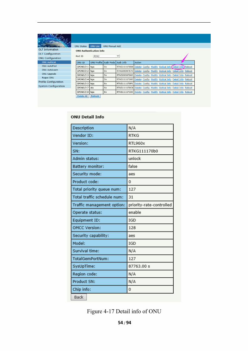
Figure 4-17 Detail info of ONU
54 / 94
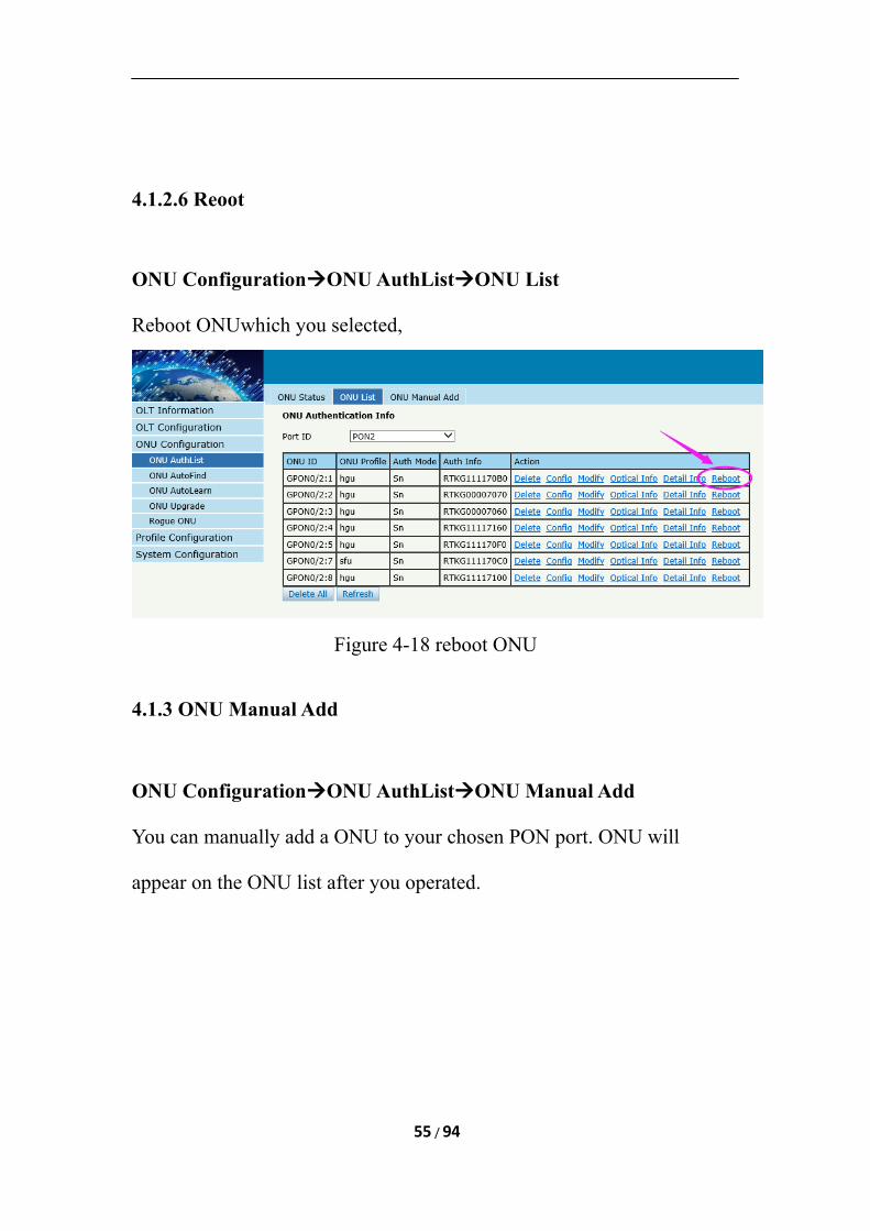
4.1.2.6 Reoot
ONU ConfigurationONU AuthListONU List
Reboot ONUwhich you selected,
Figure 4-18 reboot ONU
4.1.3 ONU Manual Add
ONU ConfigurationONU AuthListONU Manual Add
You can manually add a ONU to your chosen PON port. ONU will
appear on the ONU list after you operated.
55 / 94
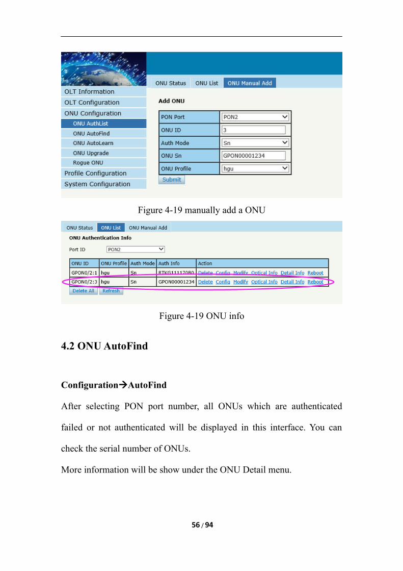
Figure 4-19 manually add a ONU
Figure 4-19 ONU info
4.2 ONU AutoFind
ConfigurationAutoFind
After selecting PON port number, all ONUs which are authenticated
failed or not authenticated will be displayed in this interface. You can
check the serial number of ONUs.
More information will be show under the ONU Detail menu.
56 / 94
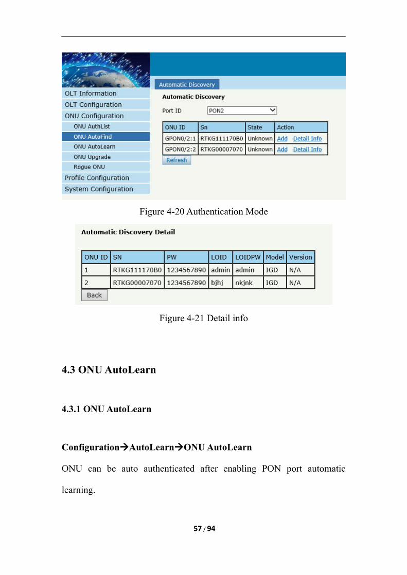
Figure 4-20 Authentication Mode
Figure 4-21 Detail info
4.3 ONU AutoLearn
4.3.1 ONU AutoLearn
ConfigurationAutoLearnONU AutoLearn
ONU can be auto authenticated after enabling PON port automatic
learning.
57 / 94
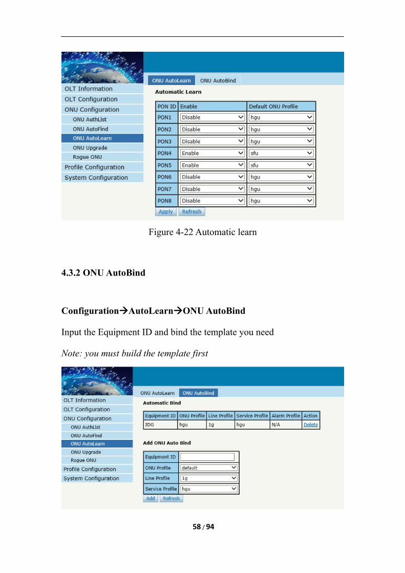
Figure 4-22 Automatic learn
4.3.2 ONU AutoBind
ConfigurationAutoLearnONU AutoBind
Input the Equipment ID and bind the template you need
Note: you must build the template first
58 / 94
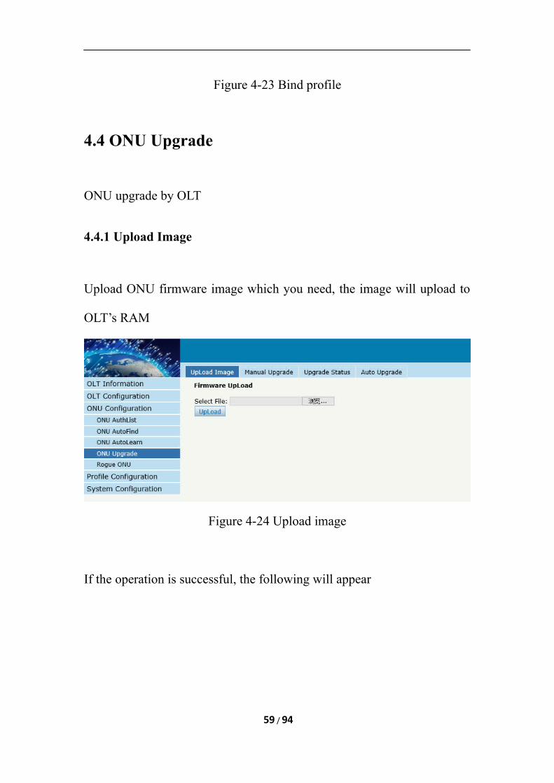
Figure 4-23 Bind profile
4.4 ONU Upgrade
ONU upgrade by OLT
4.4.1 Upload Image
Upload ONU firmware image which you need, the image will upload to
OLT’s RAM
Figure 4-24 Upload image
If the operation is successful, the following will appear
59 / 94
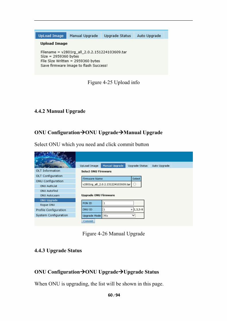
Figure 4-25 Upload info
4.4.2 Manual Upgrade
ONU ConfigurationONU UpgradeManual Upgrade
Select ONU which you need and click commit button
Figure 4-26 Manual Upgrade
4.4.3 Upgrade Status
ONU ConfigurationONU UpgradeUpgrade Status
When ONU is upgrading, the list will be shown in this page.
60 / 94
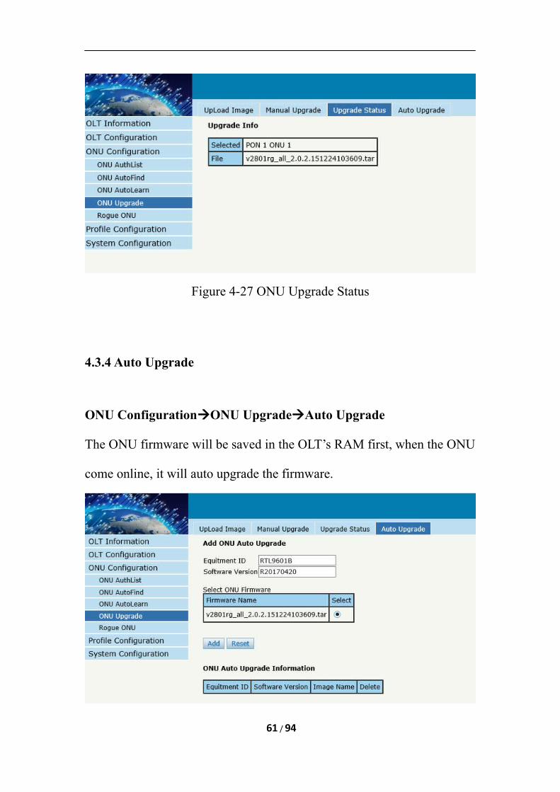
Figure 4-27 ONU Upgrade Status
4.3.4 Auto Upgrade
ONU ConfigurationONU UpgradeAuto Upgrade
The ONU firmware will be saved in the OLT’s RAM first, when the ONU
come online, it will auto upgrade the firmware.
61 / 94
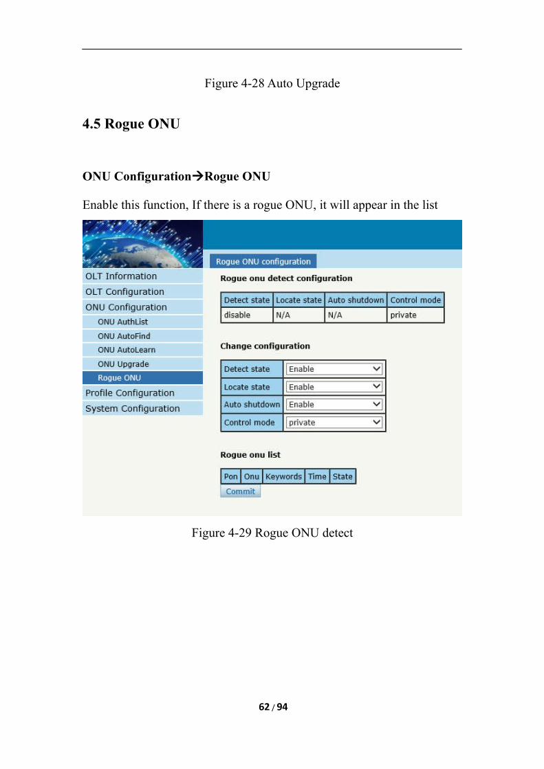
Figure 4-28 Auto Upgrade
4.5 Rogue ONU
ONU ConfigurationRogue ONU
Enable this function, If there is a rogue ONU, it will appear in the list
Figure 4-29 Rogue ONU detect
62 / 94
Chapter 5 Profile Configuration
This chapter is about the ONU profile configuration. It is designed for
batch ONU management by OLT.
5.1 ONU Profile
The Onu profile is used for onu authorization, and each ONU must specif
y only one ONU profile when authorizated. The ONU profile specifies th
e capability of this ONU.
5.1.1 Information
Profile Configuration ONU profileInformation
The table displays ONU profile list.We can also do some operation, such
delete and check details info.
63 / 94
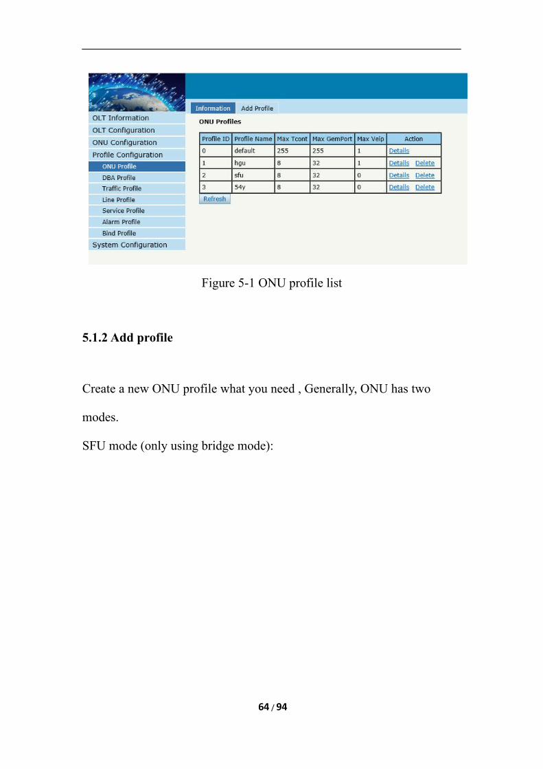
Figure 5-1 ONU profile list
5.1.2 Add profile
Create a new ONU profile what you need , Generally, ONU has two
modes.
SFU mode (only using bridge mode):
64 / 94
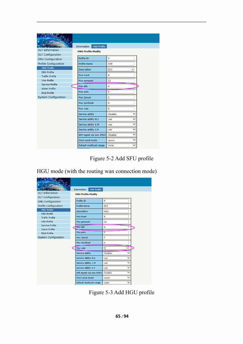
Figure 5-2 Add SFU profile
HGU mode (with the routing wan connection mode)
Figure 5-3 Add HGU profile
65 / 94
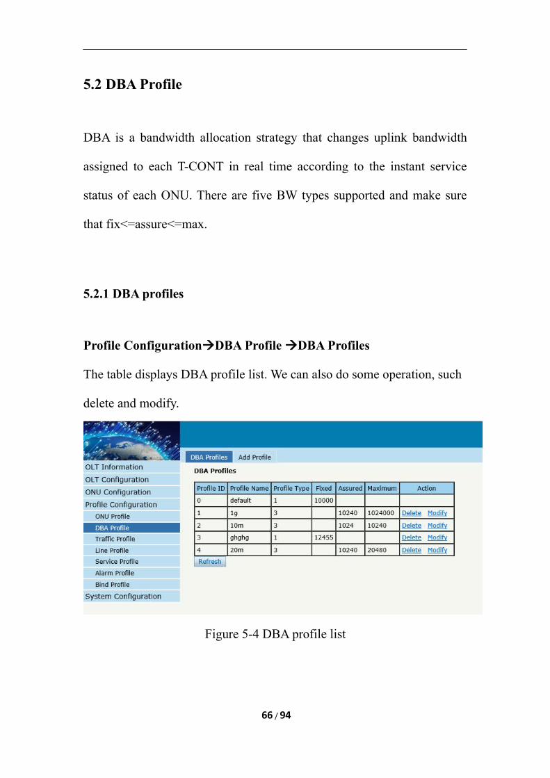
5.2 DBA Profile
DBA is a bandwidth allocation strategy that changes uplink bandwidth
assigned to each T-CONT in real time according to the instant service
status of each ONU. There are five BW types supported and make sure
that fix<=assure<=max.
5.2.1 DBA profiles
Profile ConfigurationDBA Profile DBA Profiles
The table displays DBA profile list. We can also do some operation, such
delete and modify.
Figure 5-4 DBA profile list
66 / 94
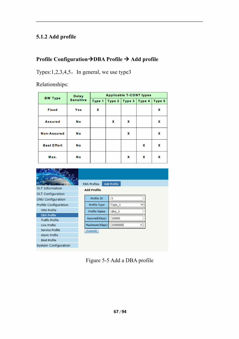
5.1.2 Add profile
Profile ConfigurationDBA Profile Add profile
Types:1,2,3,4,5,In general, we use type3
Relationships:
Figure 5-5 Add a DBA profile
67 / 94
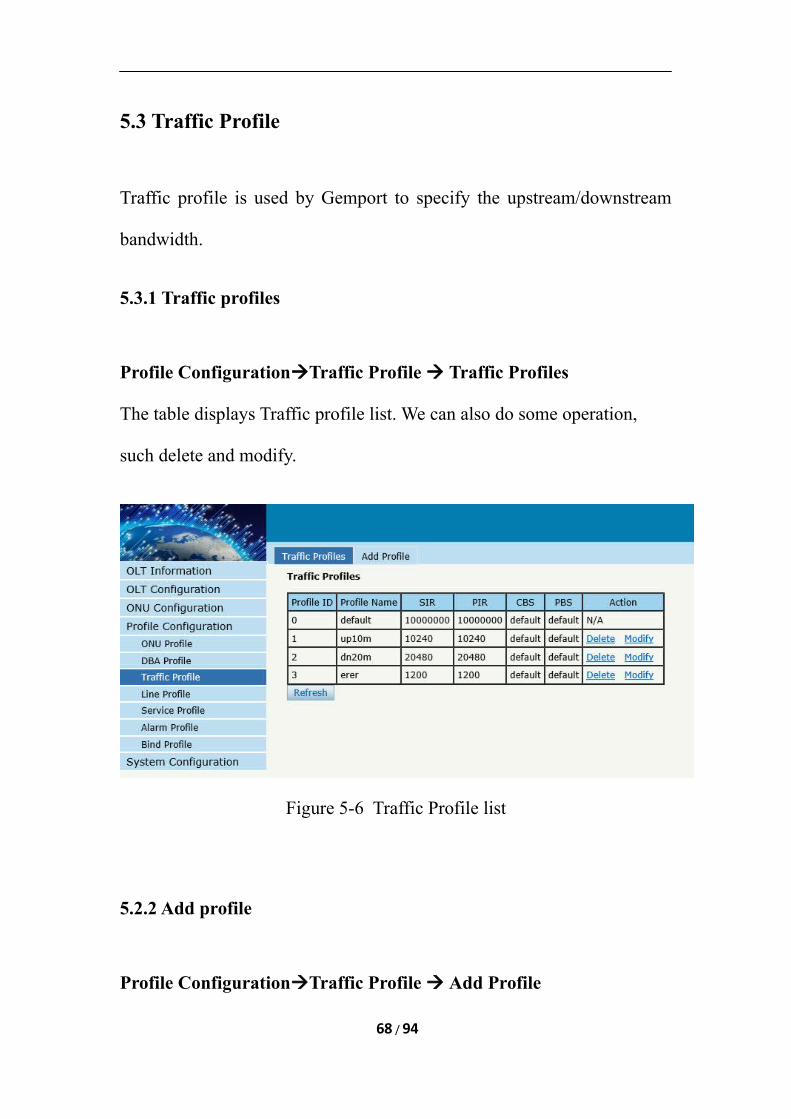
5.3 Traffic Profile
Traffic profile is used by Gemport to specify the upstream/downstream
bandwidth.
5.3.1 Traffic profiles
Profile ConfigurationTraffic Profile Traffic Profiles
The table displays Traffic profile list. We can also do some operation,
such delete and modify.
Figure 5-6 Traffic Profile list
5.2.2 Add profile
Profile ConfigurationTraffic Profile Add Profile
68 / 94
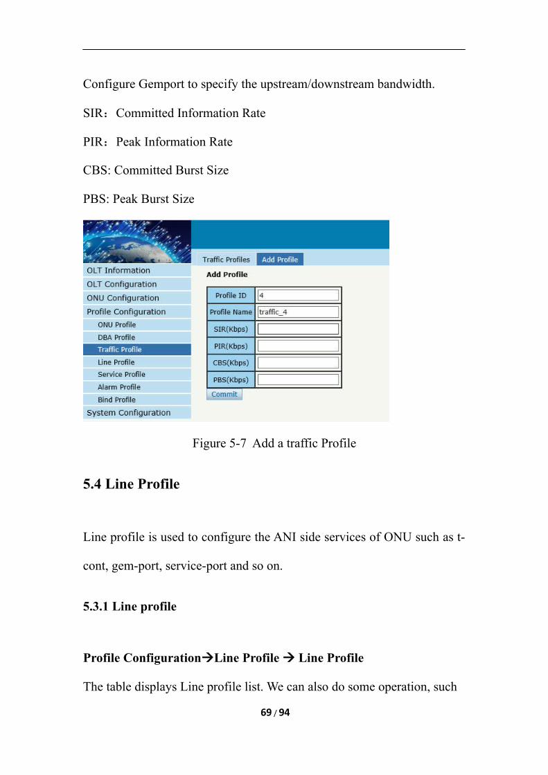
Configure Gemport to specify the upstream/downstream bandwidth.
SIR:Committed Information Rate
PIR:Peak Information Rate
CBS: Committed Burst Size
PBS: Peak Burst Size
Figure 5-7 Add a traffic Profile
5.4 Line Profile
Line profile is used to configure the ANI side services of ONU such as t-
cont, gem-port, service-port and so on.
5.3.1 Line profile
Profile ConfigurationLine Profile Line Profile
The table displays Line profile list. We can also do some operation, such
69 / 94
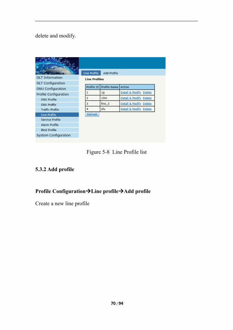
delete and modify.
Figure 5-8 Line Profile list
5.3.2 Add profile
Profile ConfigurationLine profileAdd profile
Create a new line profile
70 / 94
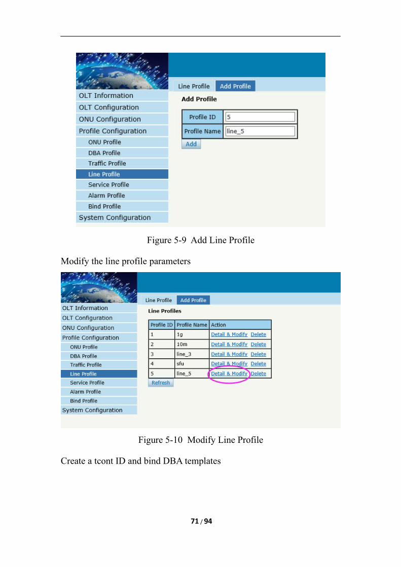
Figure 5-9 Add Line Profile
Modify the line profile parameters
Figure 5-10 Modify Line Profile
Create a tcont ID and bind DBA templates
71 / 94
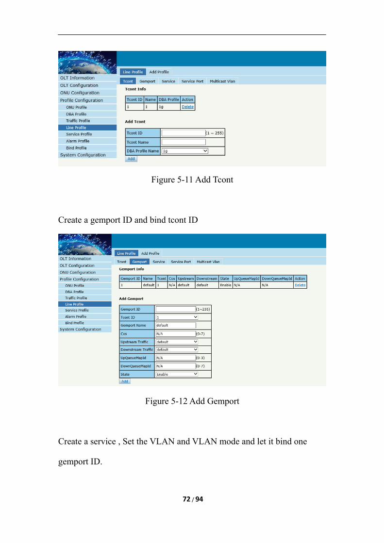
Figure 5-11 Add Tcont
Create a gemport ID and bind tcont ID
Figure 5-12 Add Gemport
Create a service , Set the VLAN and VLAN mode and let it bind one
gemport ID.
72 / 94
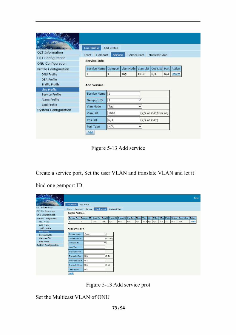
Figure 5-13 Add service
Create a service port, Set the user VLAN and translate VLAN and let it
bind one gemport ID.
Figure 5-13 Add service prot
Set the Multicast VLAN of ONU
73 / 94
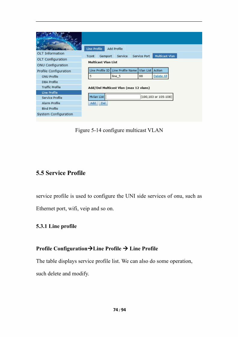
Figure 5-14 configure multicast VLAN
5.5 Service Profile
service profile is used to configure the UNI side services of onu, such as
Ethernet port, wifi, veip and so on.
5.3.1 Line profile
Profile ConfigurationLine Profile Line Profile
The table displays service profile list. We can also do some operation,
such delete and modify.
74 / 94
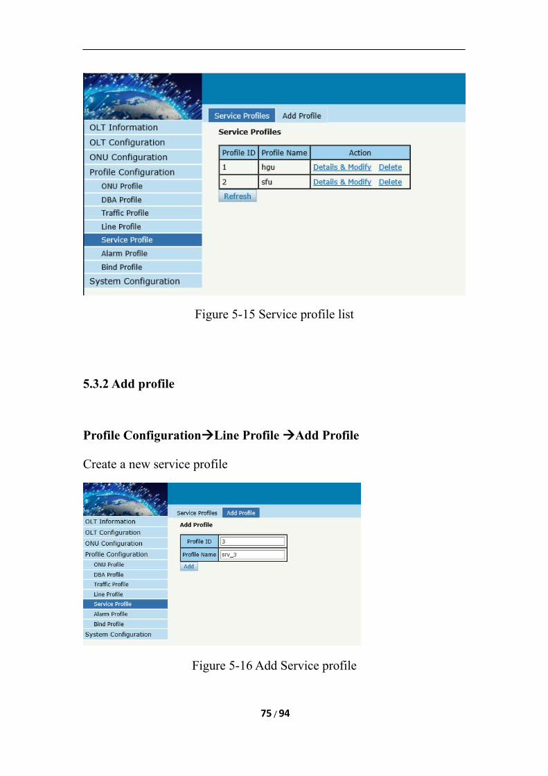
Figure 5-15 Service profile list
5.3.2 Add profile
Profile ConfigurationLine Profile Add Profile
Create a new service profile
Figure 5-16 Add Service profile
75 / 94
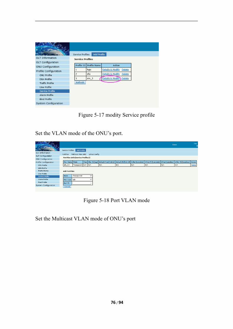
Figure 5-17 modity Service profile
Set the VLAN mode of the ONU’s port.
Figure 5-18 Port VLAN mode
Set the Multicast VLAN mode of ONU’s port
76 / 94
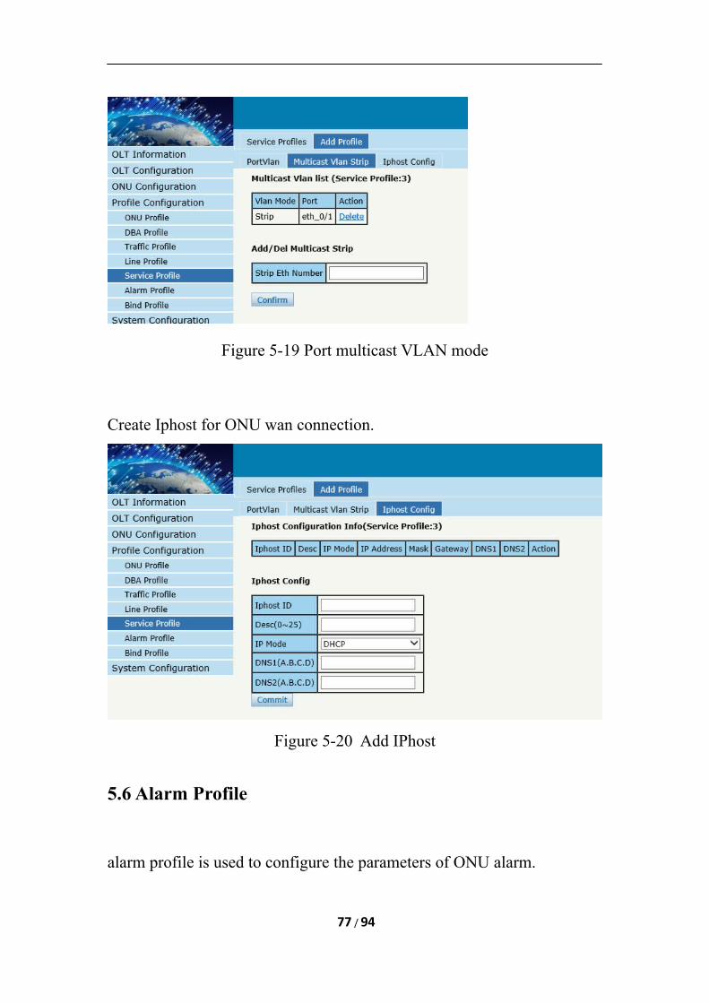
Figure 5-19 Port multicast VLAN mode
Create Iphost for ONU wan connection.
Figure 5-20 Add IPhost
5.6 Alarm Profile
alarm profile is used to configure the parameters of ONU alarm.
77 / 94
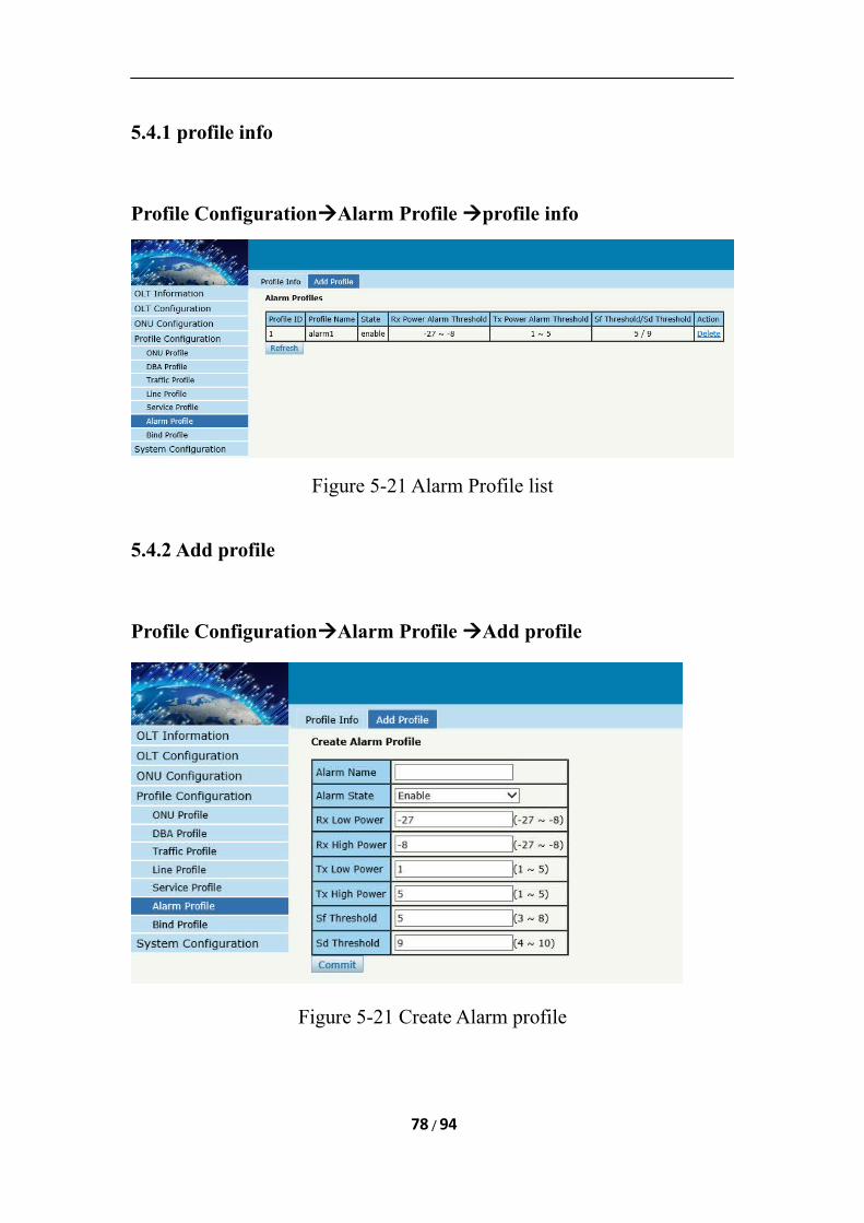
5.4.1 profile info
Profile ConfigurationAlarm Profile profile info
Figure 5-21 Alarm Profile list
5.4.2 Add profile
Profile ConfigurationAlarm Profile Add profile
Figure 5-21 Create Alarm profile
78 / 94
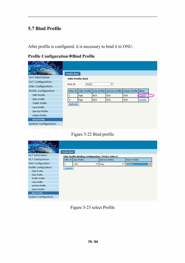
5.7 Bind Profile
After profile is configured, it is necessary to bind it to ONU.
Profile ConfigurationBind Profile
Figure 5-22 Bind profile
Figure 5-23 select Profile
79 / 94
Chapter 6 System Configuration
This chapter is about the global management of OLT.
6.1 System Log
6.1.1 System Log
System ConfigurationSystem Log
80 / 94
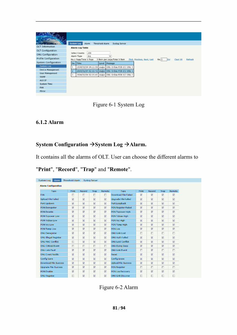
Figure 6-1 System Log
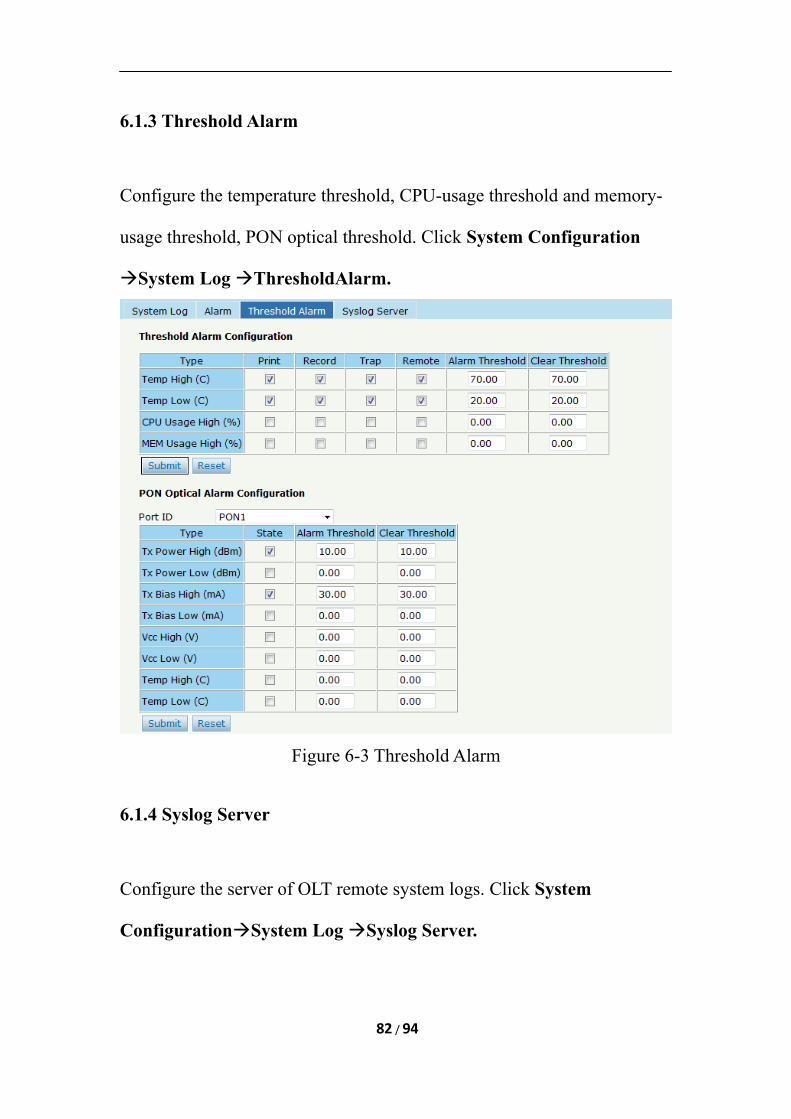
6.1.2 Alarm
System Configuration System Log Alarm.
It contains all the alarms of OLT. User can choose the different alarms to
"Print", "Record", "Trap" and "Remote".
Figure 6-2 Alarm
81 / 94
6.1.3 Threshold Alarm
Configure the temperature threshold, CPU-usage threshold and memory-
usage threshold, PON optical threshold. Click System Configuration
System Log ThresholdAlarm.
Figure 6-3 Threshold Alarm
6.1.4 Syslog Server
Configure the server of OLT remote system logs. Click System
ConfigurationSystem Log Syslog Server.
82 / 94
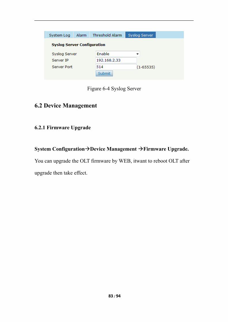
Figure 6-4 Syslog Server
6.2 Device Management
6.2.1 Firmware Upgrade
System ConfigurationDevice Management Firmware Upgrade.
You can upgrade the OLT firmware by WEB, itwant to reboot OLT after
upgrade then take effect.
83 / 94
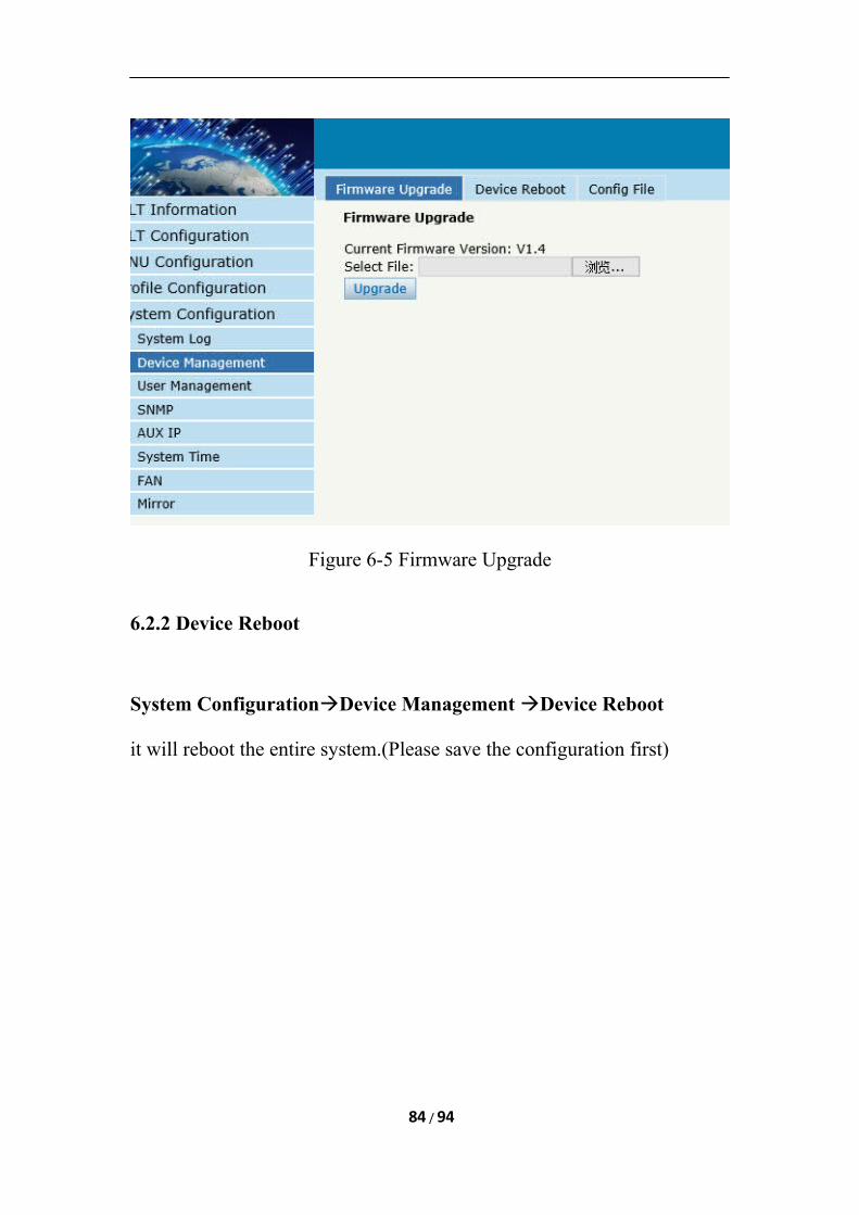
Figure 6-5 Firmware Upgrade
6.2.2 Device Reboot
System ConfigurationDevice Management Device Reboot
it will reboot the entire system.(Please save the configuration first)
84 / 94
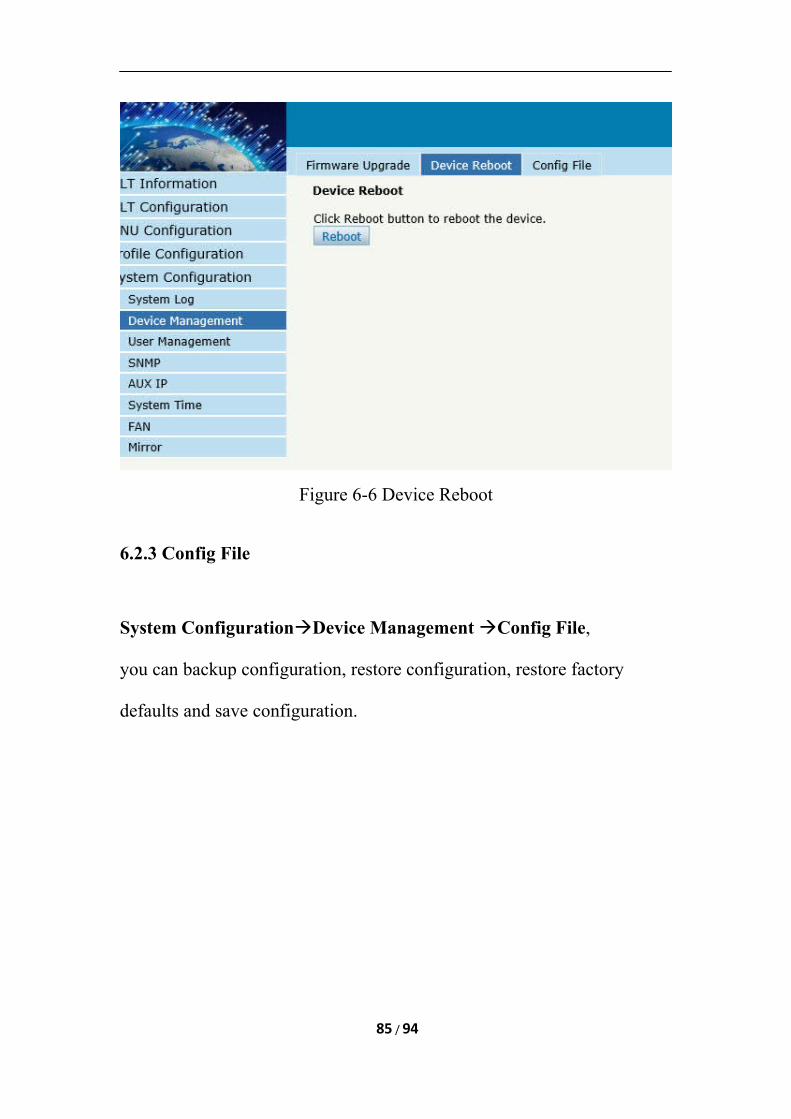
Figure 6-6 Device Reboot
6.2.3 Config File
System ConfigurationDevice Management Config File,
you can backup configuration, restore configuration, restore factory
defaults and save configuration.
85 / 94
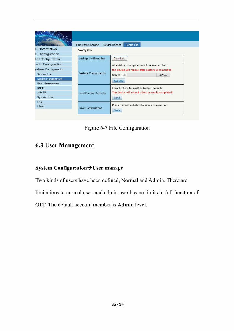
Figure 6-7 File Configuration
6.3 User Management
System ConfigurationUser manage
Two kinds of users have been defined, Normal and Admin. There are
limitations to normal user, and admin user has no limits to full function of
OLT. The default account member is Admin level.
86 / 94
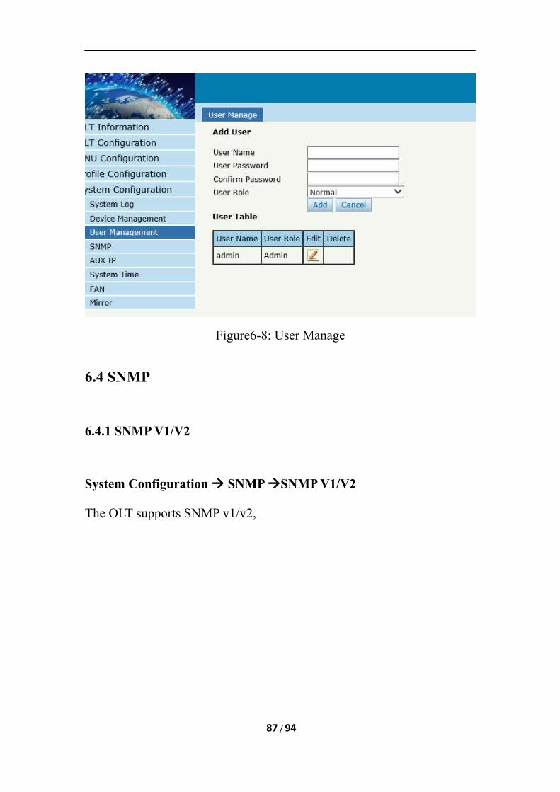
Figure6-8: User Manage
6.4 SNMP
6.4.1 SNMP V1/V2
System Configuration SNMP SNMP V1/V2
The OLT supports SNMP v1/v2,
87 / 94
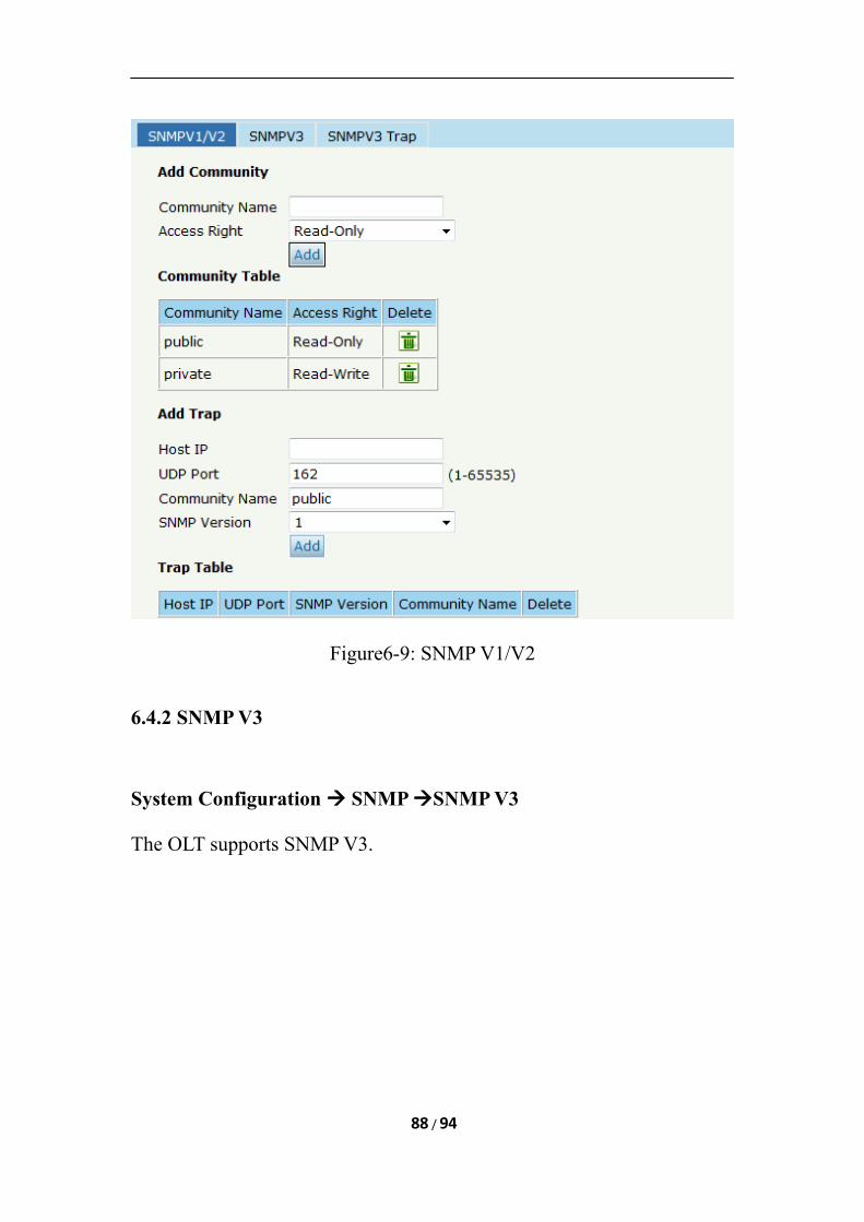
Figure6-9: SNMP V1/V2
6.4.2 SNMP V3
System Configuration SNMP SNMP V3
The OLT supports SNMP V3.
88 / 94
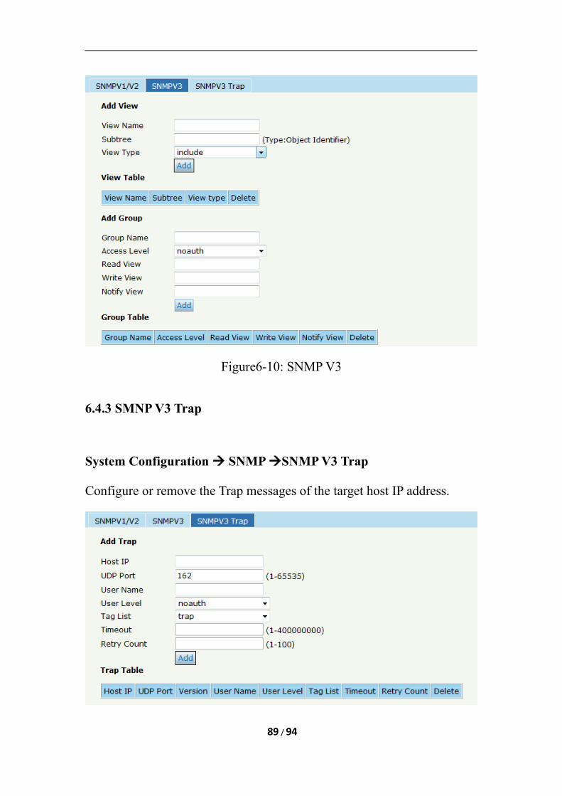
Figure6-10: SNMP V3
6.4.3 SMNP V3 Trap
System Configuration SNMP SNMP V3 Trap
Configure or remove the Trap messages of the target host IP address.
89 / 94
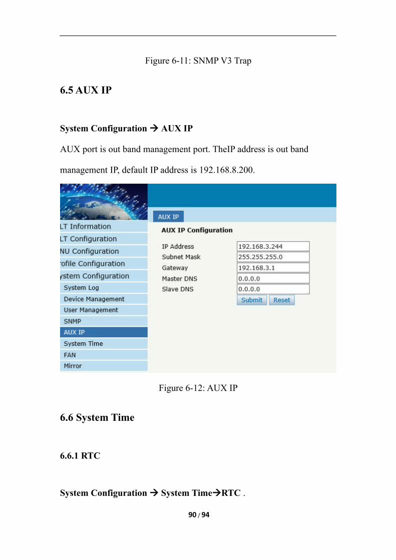
Figure 6-11: SNMP V3 Trap
6.5 AUX IP
System Configuration AUX IP
AUX port is out band management port. TheIP address is out band
management IP, default IP address is 192.168.8.200.
Figure 6-12: AUX IP
6.6 System Time
6.6.1 RTC
System Configuration System TimeRTC .
90 / 94
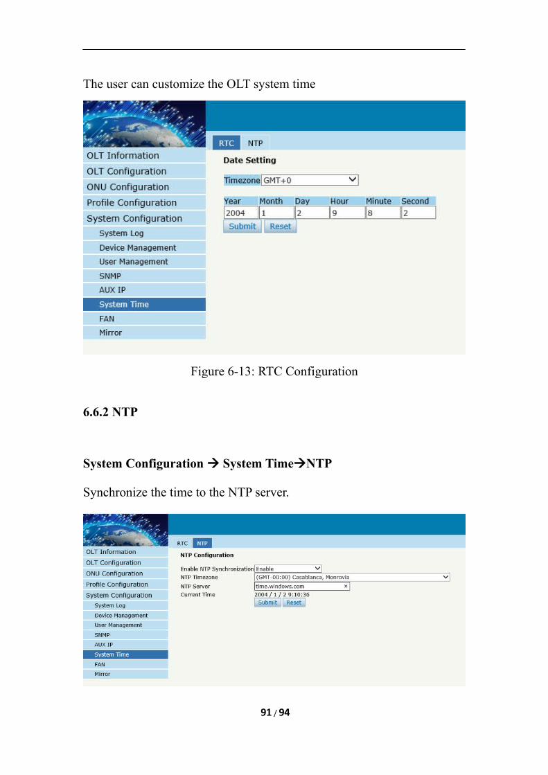
The user can customize the OLT system time
Figure 6-13: RTC Configuration
6.6.2 NTP
System Configuration System TimeNTP
Synchronize the time to the NTP server.
91 / 94
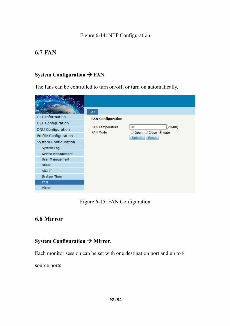
Figure 6-14: NTP Configuration
6.7 FAN
System Configuration FAN.
The fans can be controlled to turn on/off, or turn on automatically.
Figure 6-15: FAN Configuration
6.8 Mirror
System Configuration Mirror.
Each monitor session can be set with one destination port and up to 8
source ports.
92 / 94
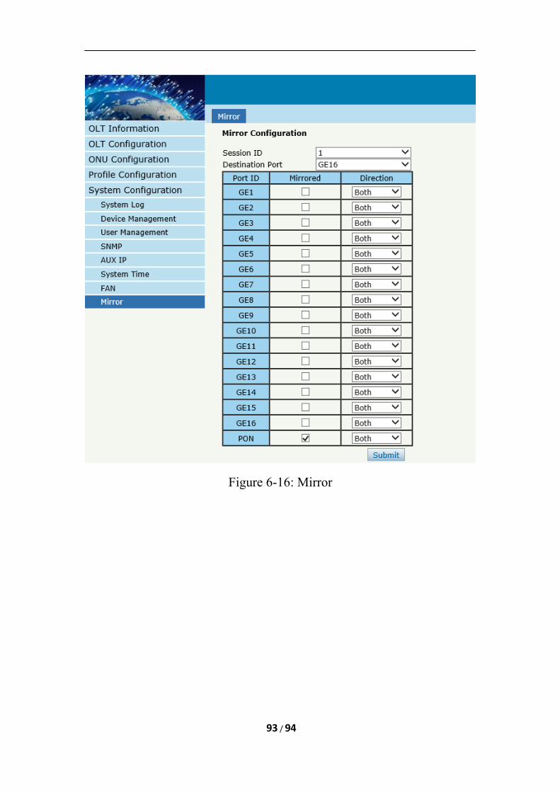
Figure 6-16: Mirror
93 / 94

Thank you!
94 / 94