Embed Size (px)
Citation preview

GPFS OverviewFebruary 15, 2002
Bill [email protected]
(925) 422-5587
This work was performed under the auspices of theU.S. Department of Energy
by the University of California,Lawrence Livermore National Laboratory
under contract No. W-7405-Eng-48.
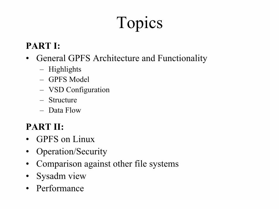
TopicsPART I:• General GPFS Architecture and Functionality
– Highlights– GPFS Model– VSD Configuration– Structure– Data Flow
PART II:• GPFS on Linux• Operation/Security• Comparison against other file systems• Sysadm view• Performance
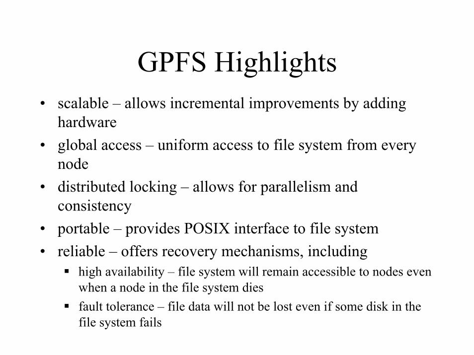
GPFS Highlights• scalable – allows incremental improvements by adding
hardware• global access – uniform access to file system from every
node• distributed locking – allows for parallelism and
consistency• portable – provides POSIX interface to file system• reliable – offers recovery mechanisms, including
high availability – file system will remain accessible to nodes even when a node in the file system diesfault tolerance – file data will not be lost even if some disk in the file system fails
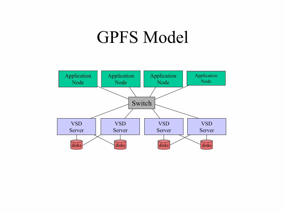
GPFS Model
Switch
Application Node
disks
Application Node
Application Node
VSD Server
disks
VSD Server
disks
VSD Server
disks
VSD Server
Application Node
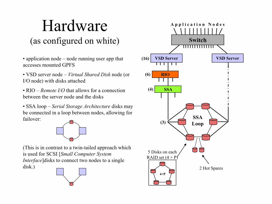
Hardware(as configured on white)
A p p l i c a t i o n N o d e s
SSALoop
5 Disks on eachRAID set (4 + P)
Switch
4+P
VSD Server
RIO
SSA
VSD Server(16)
(6)
(4)
(3)
• application node – node running user app that accesses mounted GPFS
• VSD server node – Virtual Shared Disk node (or I/O node) with disks attached
• RIO – Remote I/O that allows for a connection between the server node and the disks
• SSA loop – Serial Storage Architecture disks may be connected in a loop between nodes, allowing for failover:
(This is in contrast to a twin-tailed approach which is used for SCSI [Small Computer System Interface]disks to connect two nodes to a single disk.) 2 Hot Spares

Simple ConfigurationApplication
GPFS
VSD
Switch
CSS
VSD
LVM
DD
disks

More detailed ConfigurationAPPLICATIONS
VFS Layer
JFS GPFS
RVSD
VSD PSSP
IPLVM
LocalDisk
Switch for Data Traffic

General GPFS Structure• GPFS resides on each node as a multi-threaded daemon (called mmfsd)
and a kernel extension.• The daemon provides data and metadata management, such as disk
space allocation, data access, I/O operations, security, and quota managements.
• The kernel extensions are needed to implement the Virtual File System (VFS) layer to present GPFS as a local file system to an application.
• To access to the data disks comprising the file system, each node uses VSD/RVSD (Virtual Shared Disk and Recoverable Virtual Shared Disk).
• VSD enables nodes to share disks (a logical volume that can be accessed by any node in the system partition.) VSD is comprised of a server/client relationship.

The mmfsd daemon performs all of the I/O and buffer management, including:
• allocation of disk space• metadata management• initiation of disk I/O• implementation of security and quotas• read-ahead (prefetch) caching – analyzes read pattern and reads more
data• write-behind caching – buffers data until collects efficient write size• token management – allocation of locks for data and metadata
management
The daemon implements these global management functions through several managers.

GPFS Structure
GPFS daemon (mmfsd)
Configuration Manager
Stripe Group Manager
Token Manager
Metadata Manager
• mmfsd daemon• Global Mgt. Functions
– Configuration Manager– Stripe Group Manager– Token Manager Server– Metadata Manager
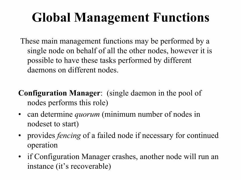
Global Management FunctionsThese main management functions may be performed by a
single node on behalf of all the other nodes, however it is possible to have these tasks performed by different daemons on different nodes.
Configuration Manager: (single daemon in the pool of nodes performs this role)
• can determine quorum (minimum number of nodes in nodeset to start)
• provides fencing of a failed node if necessary for continued operation
• if Configuration Manager crashes, another node will run an instance (it’s recoverable)

Global Management FunctionsStripe Group Manager: (single daemon in the pool performs
this per file system) (also called the File System Manager)• a ‘Stripe Group’ is a collection of disks that make up
physical storage• file system configuration – adding disks, file system repair,
etc.• disk space allocation management – handles data blocks
and inode mapping, and controls which disk regions are allocated to each node (allowing for effective parallelization)
• token management – sends token requests to Token Manager Server
• mounting/unmounting of file system• quota management• security services
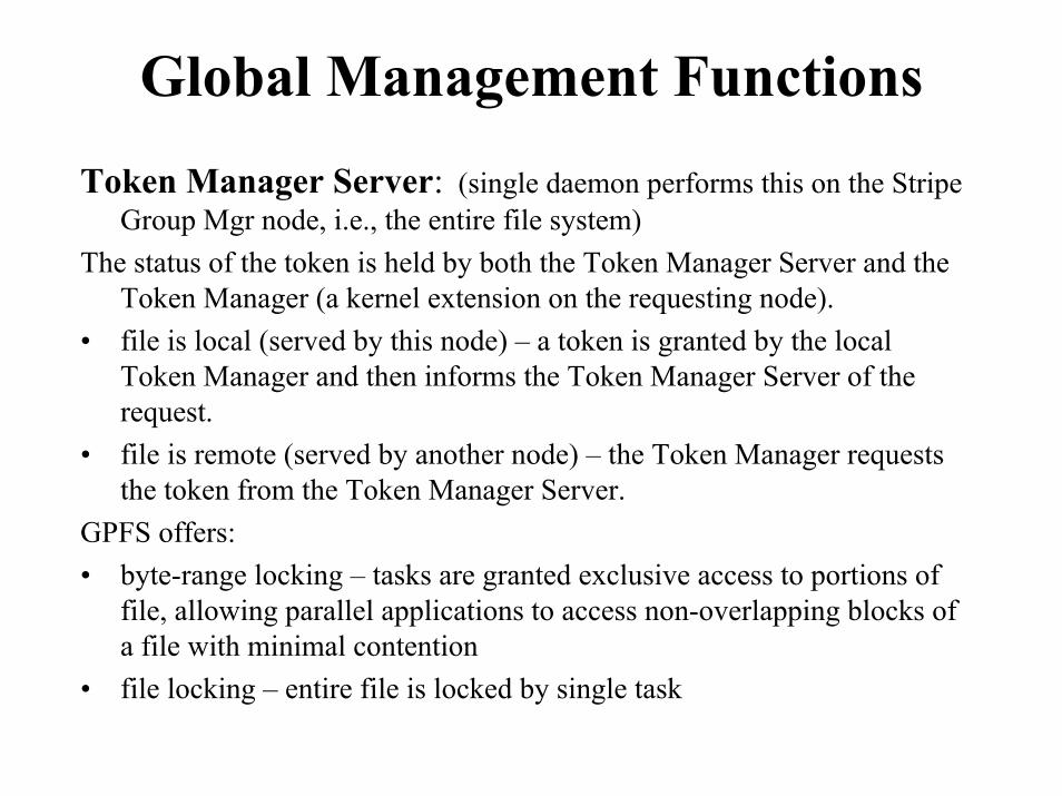
Global Management FunctionsToken Manager Server: (single daemon performs this on the Stripe
Group Mgr node, i.e., the entire file system)The status of the token is held by both the Token Manager Server and the
Token Manager (a kernel extension on the requesting node).• file is local (served by this node) – a token is granted by the local
Token Manager and then informs the Token Manager Server of the request.
• file is remote (served by another node) – the Token Manager requests the token from the Token Manager Server.
GPFS offers:• byte-range locking – tasks are granted exclusive access to portions of
file, allowing parallel applications to access non-overlapping blocks of a file with minimal contention
• file locking – entire file is locked by single task
Global Management FunctionsMetadata Manager:• metanode – for each open file, a single node is responsible
for updating that file's metadata. This node changes if another node gains access to the file.
File Structure
• Allocation– A standard i-node (index-node) structure is used for file
allocation. The i-node contains attributes of the file (size, owner, permissions, dates, pointer to data or indirect block, etc.) plus the pointer (direct or indirect) to the data blocks.
– The number of i-nodes is statically set at file system creation time and may not be altered.
File Structure
• Striping– Each file system consists of a set of VSD disks
constituting a stripe group. The purpose of striping is to improve I/O performance by allowing records to be subdivided and simultaneously written to multiple disks. Since this happens without user explicit involvement, it is called implicit parallelism.
– RAID strip width should (but might not!) match the block size of the file system. These are two different parameters.
File Structure
• Blocks can be striped in three ways:– round robin – randomly select first disk, then continue
writing blocks to successive disks– random – randomly select disk for each block– balanced random – used when disks are not same size,
randomly distributing blocks to disks in a manner proportional to their size; also described as round robin, but does not select a disk in the stripe group again until all disks have been used
File Structure
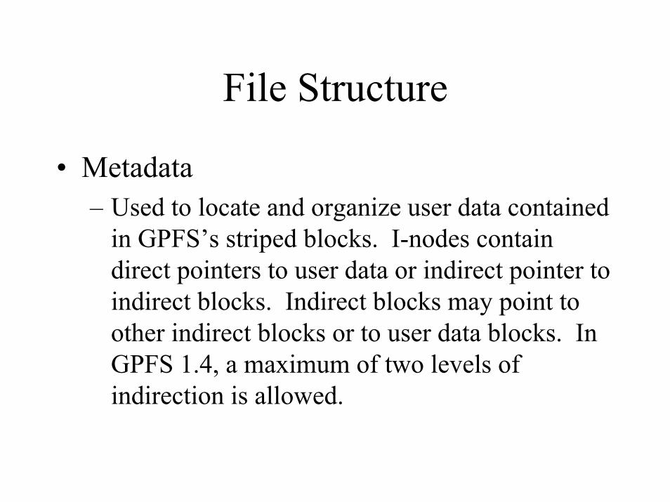
• Metadata– Used to locate and organize user data contained
in GPFS’s striped blocks. I-nodes contain direct pointers to user data or indirect pointer to indirect blocks. Indirect blocks may point to other indirect blocks or to user data blocks. In GPFS 1.4, a maximum of two levels of indirection is allowed.
File Structure
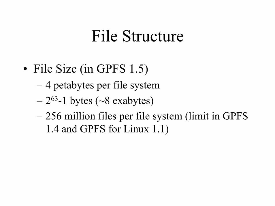
• File Size (in GPFS 1.5)– 4 petabytes per file system– 263-1 bytes (~8 exabytes)– 256 million files per file system (limit in GPFS
1.4 and GPFS for Linux 1.1)

Memory Utilization(GPFS Cache)
• The page pool is the GPFS cache of dedicated and pinned memory. (Pinned memory is memory that can not be swapped, used to increase performance.)
• The page pool allows for client-side caching, which offers a performance gain by not having to transfer data to/from disk and across the switch.
• The size of the page pool is an upper limit of the actual size of the page pool on each node. GPFS dynamically adjusts the amount necessary for the page pool to the max setting. The range is 4MB – 512MB in GPFS 1.4

CSS device driver
CSS device driver
Application NodeApplication
GPFS daemon (mmfsd)
Configuration ManagerStripe Group Manager
Token Manager
Metadata Manager
VSD layer
LVM
disk driver
disks
IP layer
I/O Server Node
(or VSD server)
DATA FLOWMODEL
user space
kernel space kernel ext. layer
VSD layer
IP layer
LVM
disk driver
Switch

Data Flow (write)
CSS device driver
CSS device driver
Application NodeApplication
bufferGPFS daemon (mmfsd)
Configuration ManagerStripe Group Manager
Token Manager
Metadata Manager
VSD layer
LVM
disk driver
disks
IP layer
I/O Server Node
(or VSD server)
1. Application on a node makes write call with pointer to buffer in user space.
user space
kernel space kernel ext. layer
VSD layer
IP layer
LVM
disk driver
Switch

Data Flow (write)
CSS device driver
CSS device driver
Application NodeApplication
bufferGPFS daemon (mmfsd)
Configuration ManagerStripe Group Manager
Token Manager
Metadata Manager
VSD layer
LVM
disk driver
disks
IP layer
I/O Server Node
(or VSD server)2. mmfsd daemon on
application node checks for lock:a. if already holds write
token, skips interaction with Token Manager Server (next two steps)
b. if local file for node, write token is acquired through Token Manager, else Token Manager Server is contacted. The Token Manager Server reports a list of files holding the token so that the requesting node may contact them directly for negotiation.
3. Token Manager Server coordinates if there is a problem with the required-byte-range requested
4. mmfsd receives Token Manager Server response of token and byte-range
user space
kernel space kernel ext. layer
VSD layer
IP layer
LVM
disk driver
Switch
Data Flow (write)
CSS device driver
CSS device driver
Application NodeApplication
bufferGPFS daemon (mmfsd)
Configuration ManagerStripe Group Manager
Token Manager
Metadata Manager
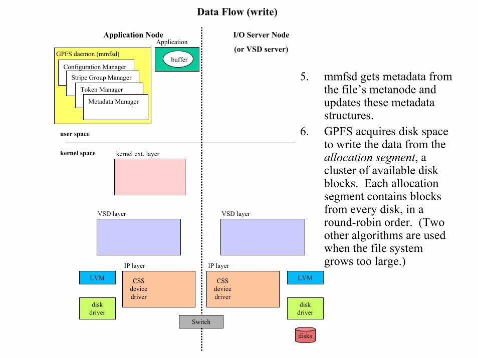
5. mmfsd gets metadata from the file’s metanode and updates these metadata structures.
6. GPFS acquires disk space to write the data from the allocation segment, a cluster of available disk blocks. Each allocation segment contains blocks from every disk, in a round-robin order. (Two other algorithms are used when the file system grows too large.)
I/O Server Node
(or VSD server)
user space
kernel space kernel ext. layer
VSD layer VSD layer
IP layer IP layer
LVM LVM
disk driver
disk driver
Switch
disks
Data Flow (write)
CSS device driver
CSS device driver
Application NodeApplication
bufferGPFS daemon (mmfsd)
Configuration ManagerStripe Group Manager
Token Manager
Metadata Manager
VSD layer
LVM
disk driver
disks
IP layer
I/O Server Node
(or VSD server)
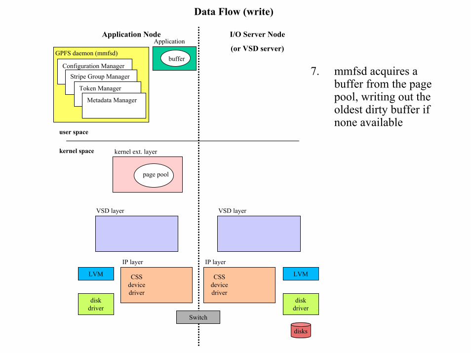
7. mmfsd acquires a buffer from the page pool, writing out the oldest dirty buffer if none available
user space
kernel space kernel ext. layer
page pool
VSD layer
IP layer
LVM
disk driver
Switch

Data Flow (write)
CSS device driver
CSS device driver
page pool
Application NodeApplication
bufferGPFS daemon (mmfsd)
Configuration ManagerStripe Group Manager
Token Manager
Metadata Manager
I/O Server Node
(or VSD server)
8. Data is moved from application data buffer to page pool buffer (currently 100MB) in kernel space
9. mmfsd schedules worker thread to continue the write of the data. At this point, the application has completed the write system call.
user space
kernel space kernel ext. layer
VSD layer VSD layer
IP layer IP layer
LVM LVM
disk driver
disk driver
Switch
disks
Data Flow (write)
CSS device driver
CSS device driver
Application NodeApplication
bufferGPFS daemon (mmfsd)
Configuration ManagerStripe Group Manager
Token Manager
Metadata Manager
VSD layer
LVM
disk driver
disks
IP layer
I/O Server Node
(or VSD server)
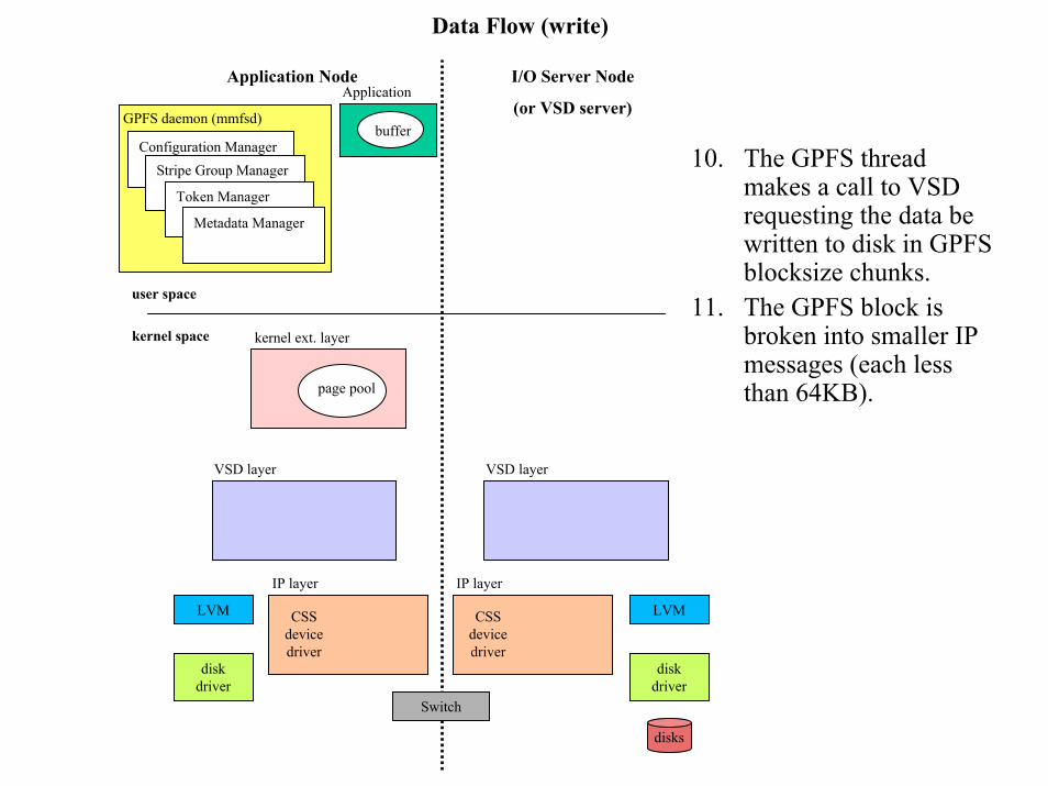
10. The GPFS thread makes a call to VSD requesting the data be written to disk in GPFS blocksize chunks.
11. The GPFS block is broken into smaller IP messages (each less than 64KB).
user space
kernel space kernel ext. layer
page pool
VSD layer
IP layer
LVM
disk driver
Switch

Data Flow (write)
CSS device driver
spool
Application NodeApplication
bufferGPFS daemon (mmfsd)
Configuration ManagerStripe Group Manager
Token Manager
Metadata Manager
VSD layer
LVM
disk driver
disks
IP layer
I/O Server Node
(or VSD server)
12. 256-byte mbufs (message buffers that are kernel data structures used for processing IP packets) are used to contain VSD and IP headers.
13. CSS (Communication SubSystem) allocates send pool (spool – a staging area for information to be sent over the switch) buffer equal to the data of each packet is allocated. Additional mbufs are allocated for tracking purposes.
user space
kernel space kernel ext. layer
page pool
VSD layer
IP layer
LVM CSS device driver
disk driver
Switch

Data Flow (write)
CSS device driver
CSS device driver
spool
page pool
I/O Server Node
(or VSD server)
Application NodeApplication
bufferGPFS daemon (mmfsd)
Configuration ManagerStripe Group Manager
Token Manager
Metadata Manager
14. VSD copies data from the page pool to the send pool. (This is a second copy.)
user space
kernel space kernel ext. layer
VSD layer VSD layer
IP layer IP layer
LVM LVM
disk driver
disk driver
Switch
disks

Data Flow (write)
CSS device driver
CSS device driver
spool
Switch
Application NodeApplication
bufferGPFS daemon (mmfsd)
Configuration ManagerStripe Group Manager
Token Manager
Metadata Manager
I/O Server Node
(or VSD server)
15. VSD client sends the IP packets (data) to the VSD server.
user space
kernel space kernel ext. layer
page pool
VSD layer VSD layer
IP layer IP layer
LVM LVM
disk driver
disk driver
disks
Data Flow (write)
CSS device driver
CSS device driver
Application NodeApplication
bufferGPFS daemon (mmfsd)
Configuration ManagerStripe Group Manager
Token Manager
Metadata Manager
VSD layer
LVM
disk driver
disks
IP layer
I/O Server Node
(or VSD server)
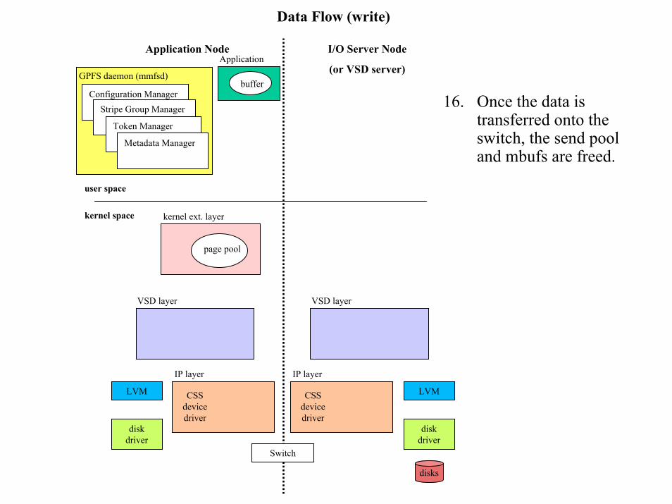
16. Once the data is transferred onto the switch, the send pool and mbufs are freed.
user space
kernel space kernel ext. layer
page pool
VSD layer
IP layer
LVM
disk driver
Switch

Data Flow (write)
rpool
CSS device driver
CSS device driver
Application NodeApplication
bufferGPFS daemon (mmfsd)
Configuration ManagerStripe Group Manager
Token Manager
Metadata Manager
VSD layer
LVM
disk driver
disks
IP layer
I/O Server Node
(or VSD server)
17. CSS allocates a receive buffer for each VSD packet in the request.
user space
kernel space kernel ext. layer
page pool
VSD layer
IP layer
LVM
disk driver
Switch

Data Flow (write)
rpool
CSS device driver
CSS device driver
Application NodeApplication
bufferGPFS daemon (mmfsd)
Configuration ManagerStripe Group Manager
Token Manager
Metadata Manager
VSD layer
LVM
disk driver
disks
IP layer
I/O Server Node
(or VSD server)
18. Upon arriving at the VSD server CSS receive pool, the data is forwarded to the VSD layer.
user space
kernel space kernel ext. layer
page pool
VSD layer
IP layer
LVM
disk driver
Switch

Data Flow (write)
rpool
CSS device driver
CSS device driver
buddy buffer
Application NodeApplication
bufferGPFS daemon (mmfsd)
Configuration ManagerStripe Group Manager
Token Manager
Metadata Manager
VSD layer
LVM
disk driver
disks
IP layer
I/O Server Node
(or VSD server)
19. Once all packets in the request have been received by the VSD server, a buddy buffer is allocated to reassemble the data. If not enough space, the request is queued and the data remains in the CSS receive pool.
user space
kernel space kernel ext. layer
page pool
VSD layer
IP layer
LVM
disk driver
Switch
Data Flow (write)
buddy buffer
LVMCSS device driver
CSS device driver
Application NodeApplication
bufferGPFS daemon (mmfsd)
Configuration ManagerStripe Group Manager
Token Manager
Metadata Manager
VSD layer
disk driver
disks
IP layer
I/O Server Node
(or VSD server)
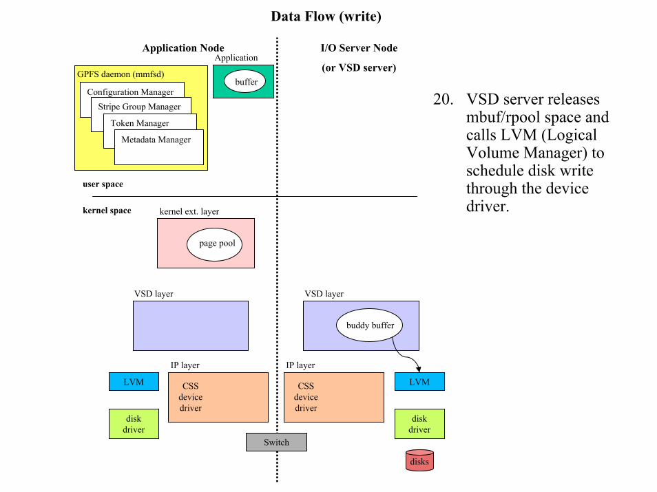
20. VSD server releases mbuf/rpool space and calls LVM (Logical Volume Manager) to schedule disk write through the device driver.
user space
kernel space kernel ext. layer
page pool
VSD layer
IP layer
LVM
disk driver
Switch

Data Flow (write)
buddy buffer
LVM
disk driver
CSS device driver
CSS device driver
Application NodeApplication
bufferGPFS daemon (mmfsd)
Configuration ManagerStripe Group Manager
Token Manager
Metadata Manager
VSD layer
disks
IP layer
I/O Server Node
(or VSD server)
21. The device driver performs the write using 256KB blocks with DMA.
user space
kernel space kernel ext. layer
page pool
VSD layer
IP layer
LVM
disk driver
Switch

Data Flow (write)
CSS device driver
CSS device driver
Application NodeApplication
bufferGPFS daemon (mmfsd)
Configuration ManagerStripe Group Manager
Token Manager
Metadata Manager
VSD layer
LVM
disk driver
disks
IP layer
I/O Server Node
(or VSD server)
22. VSD releases buddy buffer upon completion by LVM driver.
23. VSD acquires mbuf header to send completion response to VSD client.
24. VSD client releases the request block.
user space
kernel space kernel ext. layer
page pool
VSD layer
IP layer
LVM
disk driver
Switch

Data Flow (write)
CSS device driver
CSS device driver
Application NodeApplication
bufferGPFS daemon (mmfsd)
Configuration ManagerStripe Group Manager
Token Manager
Metadata Manager
VSD layer
LVM
disk driver
disks
IP layer
I/O Server Node
(or VSD server)
25. GPFS releases the page pool.
user space
kernel space kernel ext. layer
VSD layer
IP layer
LVM
disk driver
Switch

Data Flow (write) – Entire flow
buddy buffer
LVM
disk driver
disks
spool
rpool
CSS device driver
CSS device driver
spool
rpool
Switch
buddy buffer
page pool
Application NodeApplication
bufferGPFS daemon (mmfsd)
Configuration ManagerStripe Group Manager
Token Manager
Metadata Manager
The READ FLOW is similar, but in reverse. One particular issue that is different, however, is checking whether the required data is already in cache. Also, the token management is slightly different, though still preserving the consistency of the data. Again, it is the Token Manager Server that determines and resolves conflicts for a read token.
I/O Server Node
(or VSD server)
user space
kernel space kernel ext. layer
VSD layer VSD layer
IP layer IP layer
LVM
disk driver