Embed Size (px)
Citation preview
© 2007 DH Instruments, a Fluke Company
GPC1-10000/GPC1-16000™ Gas Pressure Controller
Operation and Maintenance Manual
GPC1-10000 / GPC1-16000™ OPERATION AND MAINTENANCE MANUAL
© 2007 DH Instruments, a Fluke Company
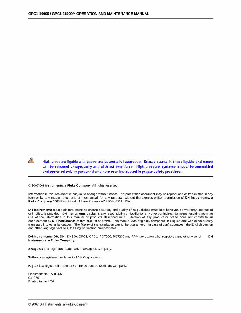
High pressure liquids and gases are potentially hazardous. Energy stored in these liquids and gases can be released unexpectedly and with extreme force. High pressure systems should be assembled and operated only by personnel who have been instructed in proper safety practices.
© 2007 DH Instruments, a Fluke Company All rights reserved.
Information in this document is subject to change without notice. No part of this document may be reproduced or transmitted in any form or by any means, electronic or mechanical, for any purpose, without the express written permission of DH Instruments, a Fluke Company 4765 East Beautiful Lane Phoenix AZ 85044-5318 USA.
DH Instruments makes sincere efforts to ensure accuracy and quality of its published materials; however, no warranty, expressed or implied, is provided. DH Instruments disclaims any responsibility or liability for any direct or indirect damages resulting from the use of the information in this manual or products described in it. Mention of any product or brand does not constitute an endorsement by DH Instruments of that product or brand. This manual was originally composed in English and was subsequently translated into other languages. The fidelity of the translation cannot be guaranteed. In case of conflict between the English version and other language versions, the English version predominates.
DH Instruments, DH, DHI, DH500, GPC1, OPG1, PG7000, PG7202 and RPM are trademarks, registered and otherwise, of DH Instruments, a Fluke Company.
Swagelok is a registered trademark of Swagelok Company.
Teflon is a registered trademark of 3M Corporation.
Krytox is a registered trademark of the Dupont de Nemours Company.
Document No. 550126A 041029 Printed in the USA
TABLE OF CONTENTS
Page I © 2007 DH Instruments, a Fluke Company
TTAABBLLEE OOFF CCOONNTTEENNTTSS
TABLE OF CONTENTS . . . . . . . . . . . . . . . . . . . . . . . . . . . . . . . . . . . . . . . . . . . . . . . . . . . . . . . . . . . . . . . I
TABLES . . . . . . . . . . . . . . . . . . . . . . . . . . . . . . . . . . . . . . . . . . . . . . . . . . . . . . . . . . . . . . . . . . . . . . . . . . . . . . . . . I I I
FIGURES . . . . . . . . . . . . . . . . . . . . . . . . . . . . . . . . . . . . . . . . . . . . . . . . . . . . . . . . . . . . . . . . . . . . . . . . . . . . . . . . I I I
ABOUT THIS MANUAL . . . . . . . . . . . . . . . . . . . . . . . . . . . . . . . . . . . . . . . . . . . . . . . . . . . . . . . . . . . . . . V
1 . INTRODUCTION . . . . . . . . . . . . . . . . . . . . . . . . . . . . . . . . . . . . . . . . . . . . . . . . . . . . . . . . . . . . . . . . . 1
1.1 PRODUCT OVERVIEW ...........................................................................................................................1 1.2 SPECIFICATIONS ...................................................................................................................................2 1.3 INSTRUMENT LAYOUT ..........................................................................................................................3
1.3.1 FRONT PANEL ..............................................................................................................................................3 1.3.2 OVERALL DIMENSIONS...............................................................................................................................3 1.3.3 SYSTEM SCHEMATIC ..................................................................................................................................4
2 . INSTALLATION . . . . . . . . . . . . . . . . . . . . . . . . . . . . . . . . . . . . . . . . . . . . . . . . . . . . . . . . . . . . . . . . . . 5
2.1 UNPACKING AND INSPECTION ............................................................................................................5 2.1.1 REMOVING FROM PACKAGING..................................................................................................................5 2.1.2 INSPECTING CONTENTS.............................................................................................................................5
2.2 SITE REQUIREMENTS............................................................................................................................6 2.3 INITIAL SETUP........................................................................................................................................7
2.3.1 SET UP GPC1................................................................................................................................................7 2.3.2 CONNECT PNEUMATIC POWER (DRIVE AIR) ...........................................................................................7 2.3.3 MAKE HIGH PRESSURE GAS SUPPLY CONNECTION .............................................................................8 2.3.4 MAKE HIGH PRESSURE GAS INTERCONNECTIONS ...............................................................................8 2.3.4.1 CONNECTING TO A DHI RPM OR PG7202 USING THE STANDARD
GPC1 INTERCONNECTIONS KIT.............................................................................................................8 2.3.4.2 OTHER HIGH PNEUMATIC PRESSURE INTERCONNECTIONS .........................................................9 2.3.4.3 RECOMMENDATIONS FOR TEST PORT CONNECTION, USE AND DUT CLEANLINESS
CONSIDERATIONS .................................................................................................................................10 2.4 POWER UP AND VERIFICATION .........................................................................................................12
2.4.1 APPLY THE HIGH PRESSURE SUPPLY ...................................................................................................12 2.4.2 ADJUST INLET PRESSURE .......................................................................................................................12 2.4.3 APPLY PDVV DRIVE PRESSURE ..............................................................................................................12 2.4.4 CHECK OPERATION OF COMPONENTS..................................................................................................13 2.4.5 PRECAUTIONS TO TAKE BEFORE GENERATING PRESSURE/SAFETY CONSIDERATIONS.............14
2.5 STORAGE AND SHIPPING...................................................................................................................14 2.6 SPECIAL CONSIDERATIONS FOR HYDROCARBON FREE OPERATION........................................15
GPC1-10000 / GPC1-16000™ OPERATION AND MAINTENANCE MANUAL
© 2007 DH Instruments, a Fluke Company Page II
3 . OPERATION . . . . . . . . . . . . . . . . . . . . . . . . . . . . . . . . . . . . . . . . . . . . . . . . . . . . . . . . . . . . . . . . . . . . . 17
3.1 OPERATING PRINCIPLE ......................................................................................................................17 3.2 OPERATIONAL FUNCTIONS................................................................................................................19
3.2.1 SETTING INLET SUPPLY PRESSURE, TEST INLET REGULATOR ADJUSTMENT...............................19 3.2.2 ROUGH PRESSURE GENERATION/CONTROL, INLET AND OUTLET VALVE OPERATION ................20 3.2.3 FINE PRESSURE ADJUSTMENT, PDVV (+) AND (-) VALVE OPERATION .............................................20 3.2.4 CONNECTING A DEVICE UNDER TEST (DUT).........................................................................................21 3.2.5 PURGING LIQUIDS FROM THE DUT/SYSTEM UNDER TEST ..................................................22
3.3 TYPICAL OPERATING SEQUENCE FOR A COMPLETE CALIBRATION OR TEST ..........................22
4. MAINTENANCE AND ADJUSTMENTS . . . . . . . . . . . . . . . . . . . . . . . . . . . . . . . . . . 23
4.1 OVERVIEW............................................................................................................................................23 4.2 PURGING THE SUMP (DRAIN).............................................................................................................24 4.3 CLEANING/REPLACING PDVV DRIVE AIR FILTER ELEMENT ............................................24
5 . TROUBLESHOOTING . . . . . . . . . . . . . . . . . . . . . . . . . . . . . . . . . . . . . . . . . . . . . . . . . . . . . . . . 27
6 . APPENDICES . . . . . . . . . . . . . . . . . . . . . . . . . . . . . . . . . . . . . . . . . . . . . . . . . . . . . . . . . . . . . . . . . . . 29
6.1 GPC1 TERMS, LABELS, AND SYMBOLS (GLOSSARY) ....................................................................29 6.2 WARRANTY STATEMENT....................................................................................................................30
TABLES AND FIGURES
Page III © 2007 DH Instruments, a Fluke Company
TTAABBLLEESS
Table 1. GPC1 Parts List ............................................................................................................................. 5 Table 2. Pneumatic Power (Drive Air) Requirements.................................................................................. 7 Table 3. GPC1 Troubleshooting Checklist................................................................................................. 27 Table 4. DHI Authorize d Service Providers .............................................................................................. 30
FFIIGGUURREESS
Figure 1. Front Panel View .......................................................................................................................... 3 Figure 2. Front and Side Views with Dimensions ........................................................................................ 3 Figure 3. System Schematic ........................................................................................................................ 4 Figure 4. Connecting GPC1 to PG7202 or RPM ......................................................................................... 9 Figure 5. Clean TEST Port, Sump and Drain Port..................................................................................... 11 Figure 6. System Schematic ...................................................................................................................... 18 Figure 7. Front Panel View ........................................................................................................................ 19 Figure 8. PDVV Plunger Position Indicator................................................................................................ 21 Figure 9. Drain Port Location ..................................................................................................................... 24 Figure 10. PDVV Drive Air Filter ................................................................................................................ 25

GPC1-10000 / GPC1-16000™ OPERATION AND MAINTENANCE MANUAL
© 2007 DH Instruments, a Fluke Company Page IV
NNOOTTEESS
ABOUT THIS MANUAL
Page V © 2007 DH Instruments, a Fluke Company
AABBOOUUTT TTHHIISS MMAANNUUAALL
This manual provides the user with the information necessary to operate a GPC1 Gas Pressure Controller. It also includes a great deal of additional information provided to help you optimize GPC1 use and take full advantage of its many features and functions.
FOR THOSE OF YOU WHO “DON’T READ MANUALS”, GO DIRECTLY TO SECTION 2.3 TO SET UP YOUR GPC1. THEN GO TO SECTIONS 2.4.5 and 3.1. THIS WILL GET YOU RUNNING QUICKLY WITH MINIMAL RISK OF CAUSING DAMAGE TO YOURSELF OR YOUR GPC1. THEN… WHEN YOU HAVE QUESTIONS OR START TO WONDER ABOUT ALL THE GREAT FEATURES YOU MIGHT BE MISSING, GET INTO THE MANUAL!
Manual Conventions
(Caution) is used throughout the manual to identify user warnings and cautions.
(NOTE) is used throughout the manual to identify operating and applications advice and additional explanations.

GPC1-10000 / GPC1-16000™ OPERATION AND MAINTENANCE MANUAL
© 2007 DH Instruments, a Fluke Company Page VI
NNOOTTEESS
1. INTRODUCTION
Page 1 © 2007 DH Instruments, a Fluke Company
11.. IINNTTRROODDUUCCTTIIOONN
1.1 PRODUCT OVERVIEW The GPC1 Gas Pressure Controller is a stand alone, pressure setting and adjusting component intended to be used as the means of pressure control in high pressure pneumatic calibration and test systems. There are two models. GPC1-16000 is capable of both setting and precisely adjusting pressure from atmosphere to 110 MPa (16 000 psi). GPC1-10000 covers the range from atmosphere to 70 MPa (10 000 psi).
GPC1 combines the versatility, speed and reliability of direct operator control with the convenience and effort-free operation of automation. It is the standard pressure control component in a DHI PG7202™ piston gauge system or with a DHI RPM™ digital reference pressure monitor to configure a transfer standard based calibration system.
GPC1 requires an external pressure supply equal to the maximum pressure to be adjusted. This is usually supplied by a gas booster. GPC1’s inlet pressure regulator and indicating gauge are used to set the inlet pressure to the desired value for the test being run. Two (2) progressive, half-turn needle valves control the inlet of pressure from the regulator to increase pressure and outlet to atmosphere to decrease pressure. Very fine pressure adjustment and generation of small pressure excursions is accomplished using a Pneumatically Driven Variable Volume (PDVV) with push button control. Pneumatic power (drive air) of up to 850 kPa (120 psi) is needed to drive the PDVV. All of the test connections are routed through an inclined manifold that serves as a sump to collect liquids and other contaminants that may return from devices connected to GPC1. The sump includes a drain for purging.
GPC1-10000 / GPC1-16000™ OPERATION AND MAINTENANCE MANUAL
© 2007 DH Instruments, a Fluke Company Page 2
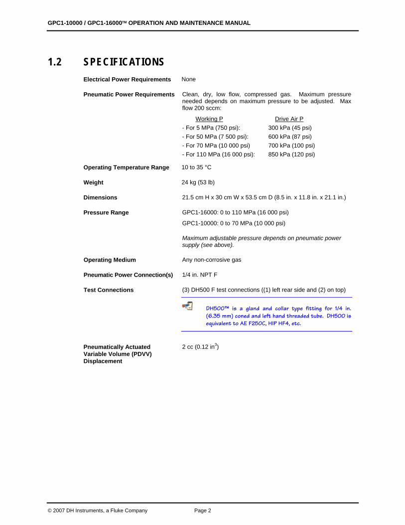
1.2 SPECIFICATIONS Electrical Power Requirements None
Pneumatic Power Requirements Clean, dry, low flow, compressed gas. Maximum pressure needed depends on maximum pressure to be adjusted. Max flow 200 sccm:
Working P Drive Air P - For 5 MPa (750 psi): 300 kPa (45 psi) - For 50 MPa (7 500 psi): 600 kPa (87 psi) - For 70 MPa (10 000 psi) 700 kPa (100 psi) - For 110 MPa (16 000 psi): 850 kPa (120 psi)
Operating Temperature Range 10 to 35 °C
Weight 24 kg (53 lb)
Dimensions 21.5 cm H x 30 cm W x 53.5 cm D (8.5 in. x 11.8 in. x 21.1 in.)
Pressure Range
GPC1-16000: 0 to 110 MPa (16 000 psi)
GPC1-10000: 0 to 70 MPa (10 000 psi)
Maximum adjustable pressure depends on pneumatic power supply (see above).
Operating Medium Any non-corrosive gas
Pneumatic Power Connection(s) 1/4 in. NPT F
Test Connections (3) DH500 F test connections ((1) left rear side and (2) on top)
DH500™ is a gland and collar type fitting for 1/4 in.(6.35 mm) coned and left hand threaded tube. DH500 is equivalent to AE F250C, HIP HF4, etc.
Pneumatically Actuated Variable Volume (PDVV) Displacement
2 cc (0.12 in3)
1. 4BINTRODUCTION
Page 3 © 2007 DH Instruments, a Fluke Company
1.3 INSTRUMENT LAYOUT
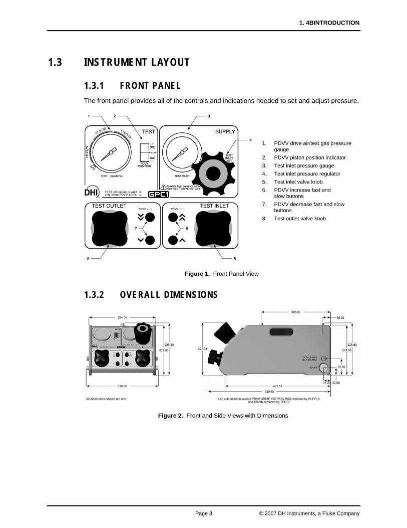
1.3.1 FRONT PANEL The front panel provides all of the controls and indications needed to set and adjust pressure.
Figure 1. Front Panel View
1.3.2 OVERALL DIMENSIONS
Figure 2. Front and Side Views with Dimensions
1. PDVV drive air/test gas pressure gauge
2. PDVV piston position indicator 3. Test inlet pressure gauge 4. Test inlet pressure regulator 5. Test inlet valve knob 6. PDVV increase fast and
slow buttons 7. PDVV decrease fast and slow
buttons 8. Test outlet valve knob
GPC1-10000 / GPC1-16000™ OPERATION AND MAINTENANCE MANUAL
© 2007 DH Instruments, a Fluke Company Page 4
1.3.3 SYSTEM SCHEMATIC
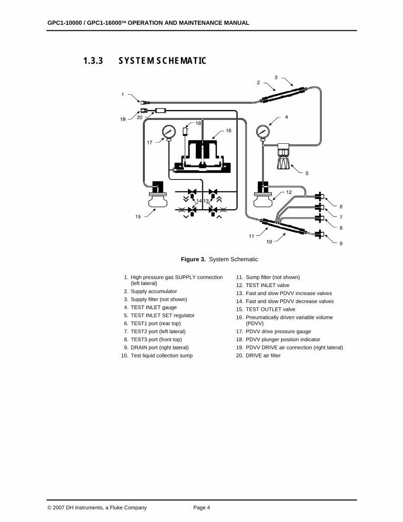
Figure 3. System Schematic
1. High pressure gas SUPPLY connection
(left lateral) 2. Supply accumulator 3. Supply filter (not shown) 4. TEST INLET gauge 5. TEST INLET SET regulator 6. TEST1 port (rear top) 7. TEST2 port (left lateral) 8. TEST3 port (front top) 9. DRAIN port (right lateral)
10. Test liquid collection sump
11. Sump filter (not shown) 12. TEST INLET valve 13. Fast and slow PDVV increase valves 14. Fast and slow PDVV decrease valves 15. TEST OUTLET valve 16. Pneumatically driven variable volume
(PDVV) 17. PDVV drive pressure gauge 18. PDVV plunger position indicator 19. PDVV DRIVE air connection (right lateral) 20. DRIVE air filter
2. INSTALLATION
Page 5 © 2007 DH Instruments, a Fluke Company
22.. IINNSSTTAALLLLAATTIIOONN
2.1 UNPACKING AND INSPECTION
2.1.1 REMOVING FROM PACKAGING GPC1 is delivered, along with its standard accessories, in a corrugated container with corrugated and polyurethane inserts to hold it in place.
Remove GPC1 and its accessories from the shipping container and remove each item from its protective plastic bag.
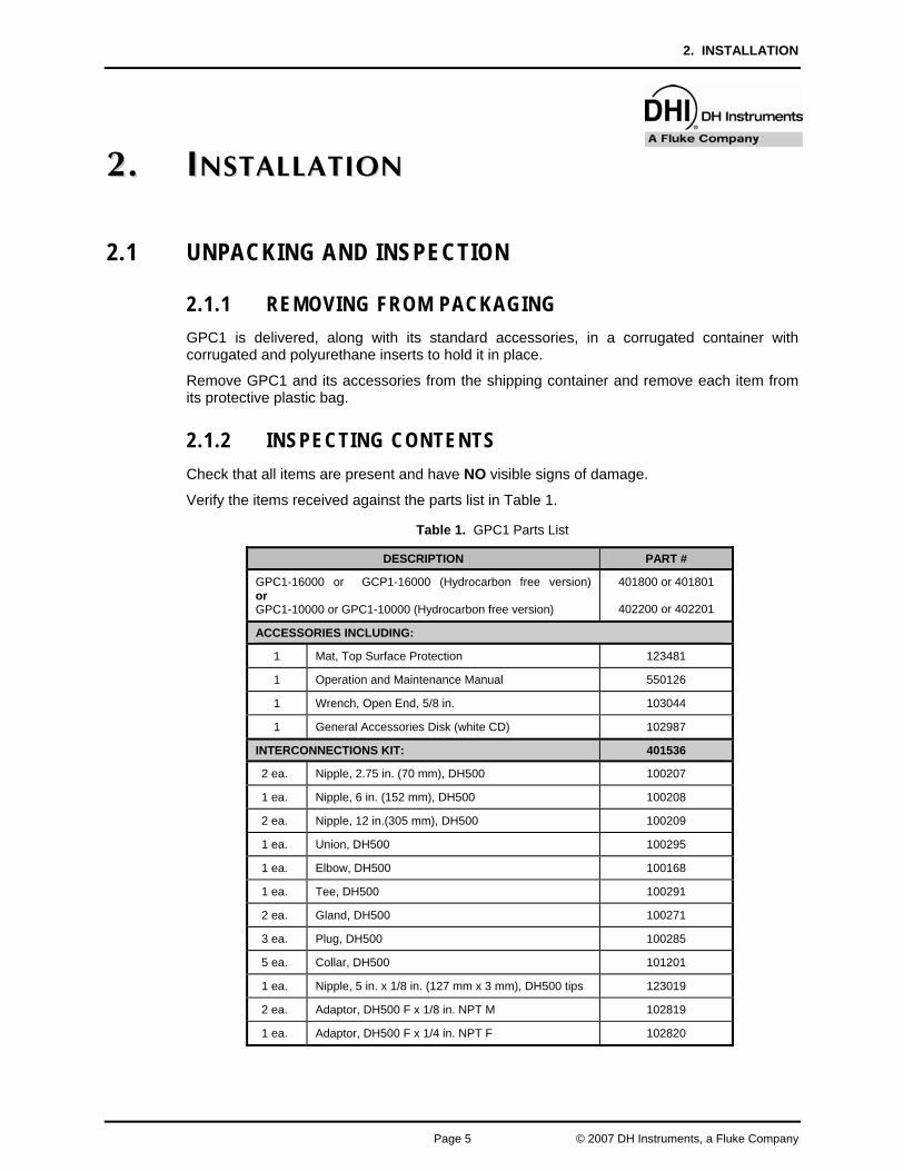
2.1.2 INSPECTING CONTENTS Check that all items are present and have NO visible signs of damage.
Verify the items received against the parts list in Table 1.
Table 1. GPC1 Parts List
DESCRIPTION PART #
GPC1-16000 or GCP1-16000 (Hydrocarbon free version)or GPC1-10000 or GPC1-10000 (Hydrocarbon free version)
401800 or 401801
402200 or 402201
ACCESSORIES INCLUDING:
1 Mat, Top Surface Protection 123481
1 Operation and Maintenance Manual 550126
1 Wrench, Open End, 5/8 in. 103044
1 General Accessories Disk (white CD) 102987
INTERCONNECTIONS KIT: 401536
2 ea. Nipple, 2.75 in. (70 mm), DH500 100207
1 ea. Nipple, 6 in. (152 mm), DH500 100208
2 ea. Nipple, 12 in.(305 mm), DH500 100209
1 ea. Union, DH500 100295
1 ea. Elbow, DH500 100168
1 ea. Tee, DH500 100291
2 ea. Gland, DH500 100271
3 ea. Plug, DH500 100285
5 ea. Collar, DH500 101201
1 ea. Nipple, 5 in. x 1/8 in. (127 mm x 3 mm), DH500 tips 123019
2 ea. Adaptor, DH500 F x 1/8 in. NPT M 102819
1 ea. Adaptor, DH500 F x 1/4 in. NPT F 102820
GPC1-10000 / GPC1-16000™ OPERATION AND MAINTENANCE MANUAL
© 2007 DH Instruments, a Fluke Company Page 6
2.2 SITE REQUIREMENTS The GPC1 system installation is affected by the other components that make up the system in which GPC1 is being used. Generally, a pressure measuring reference such as a piston gauge or transfer standard is included.
When selecting and preparing a site to setup a GPC1 system, the following should be considered:
• Bench Stability: GPC1 weighs about 24 kg (53 lb). Consider its weight and that of other components, including possible items to be tested, when selecting a bench.
• Location of Other Components: Plan the space required and a convenient layout for the complete system in which GPC1 is the pressure control component. GPC1 has a TEST2 port on its left rear side. In order to position GPC1 to the right for right-handed access, this is where the reference is usually connected in a calibration system. If necessary, as an alternative, either of the two (2) top TEST ports can also be used (see Section 2.3.4). Select interconnecting tubing and fittings rated to handle the maximum pressure that will be generated. GPC1 high pressure fittings are all DH500 (equivalent to AE F250C, HIP HF4, etc.). The female DH500 TEST ports and SUPPLY port fittings are delivered with glands nuts and dummy plastic plugs installed.
If you do not plan to use either of GPC1’s top TEST ports, consider where a device or system under test (DUT) will be connected. Note, however, that the top rear TEST1 port is the “clean” TEST port (see Section 2.3.4.3). Unused TEST ports must be plugged for operation using the DH 500 plugs supplied in the GPC1 interconnections kit.
If GPC1 is to be used with a DHI RPM or PG7202 reference device, the hardware necessary for setting up in a standard configuration is included in the GPC1 interconnections kit (see Section 2.3.4.1).
• High Pressure Supply: Plan the high pressure supply to GPC1. If the high pressure is being supplied by a DHI gas booster, interconnecting hardware to connect the booster output to GPC1 SUPPLY port is included with the booster (see the gas booster Operation and Maintenance Manual). The GPC1 SUPPLY port is DH500 female (DH500 is equivalent to AE F250C, HIP HF4, etc.).
• Drive Air Supply: Plan the PDVV drive air supply. The maximum drive air supply is 850 kPa (120 psi) but may be lower depending on the maximum test pressure to be adjusted (see Section 2.3.2, Table 2). The drive air PDVV DRIVE AIR port is on the right, rear side of GPC1. The connection is 1/4 in. NPT female.
• System Interconnections: Plan the interconnections between GPC1 and other components in the system. Minimizing the volume and maximizing the mass of all interconnecting elements will reduce pressure generation and stabilization time (see Section 2.3.4).
ALWAYS use external tubing and fittings rated for pressures equal to or greater than the maximum pressure which GPC1 will be used to control.
DH500 F fittings are delivered with disposable, orange, plastic dummy plugs installed. These are NOT intended to hold high pressure. They should be removed and replaced with appropriate fittings or stainless steel plugs before high pressure operation. Each dummy plug carries a DH500 collar. Remove and retain the collar for use in connecting to the fitting.
2. 5BINSTALLATION
Page 7 © 2007 DH Instruments, a Fluke Company
2.3 INITIAL SETUP
Before setting up GPC1, see Section 2.2 for general information on site requirements.
To prepare a GPC1 for check out and operation:
Set up GPC1 (see Section 2.3.1).
Connect drive air (see Section 2.3.2).
Connect the high pressure supply (see Section 2.3.3)
Make the system high pressure gas interconnections (see Section 2.3.4).
2.3.1 SET UP GPC1 To set up GPC1 proceed as follows:
Place GPC1 on the site table in the proper orientation with the front panel controls conveniently accessible.
Install the mat delivered with the GPC1 accessories on the top, front surface of the GPC1.
2.3.2 CONNECT PNEUMATIC POWER (DRIVE AIR) GPC1 requires pneumatic power to drive its pneumatically driven variable volume (PDVV) (see Figure 3).
The drive air requirements are summarized in Table 2. Since the flow requirements are very low and cleanliness of the gas is important, the supply is usually regulated Nitrogen or instrument grade air from a compressed air bottle.
Connect the pneumatic pressure source to the 1/4 in. NPT F connection labeled PDVV DRIVE on the right side of GPC1 housing. Use Teflon™ tape or another thread sealant to minimize leakage.
GPC1 must be supplied with NON-LUBRICATED drive air. The internal components are permanently lubricated. The oil in lubricated air can contaminate the small diameter tubing inside GPC1 and lead to erratic behavior requiring difficult and costly cleaning.
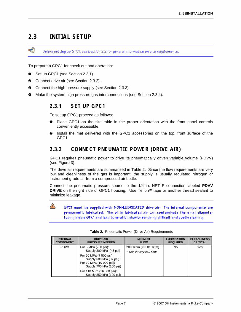
Table 2. Pneumatic Power (Drive Air) Requirements
INTERNAL COMPONENT
DRIVE AIR PRESSURE NEEDED
MINIMUM FLOW
LUBRICATION REQUIRED
CLEANLINESSCRITICAL
PDVV For 5 MPa (750 psi): Supply 300 kPa (45 psi) For 50 MPa (7 500 psi): Supply 600 kPa (87 psi) For 70 MPa (10 000 psi): Supply 700 kPa (100 psi) For 110 MPa (16 000 psi): Supply 850 kPa (120 psi)
200 sccm (< 0.01 scfm) * This is very low flow.
No Yes
GPC1-10000 / GPC1-16000™ OPERATION AND MAINTENANCE MANUAL
© 2007 DH Instruments, a Fluke Company Page 8
2.3.3 MAKE HIGH PRESSURE GAS SUPPLY CONNECTION GPC1 requires a high pressure gas supply equal to or less than the maximum desired test pressure. This is often supplied by a DHI gas booster.
If a DHI gas booster is being used for the high pressure gas supply, interconnections to connect the booster output to the GPC1 SUPPLY port are supplied with the booster. See the booster Operation and Maintenance Manual for details on setting up the connection.
The high pressure gas supply is connected to the GPC1 SUPPLY port. The SUPPLY port is a DH500 female (DH500 is equivalent to AE F250C, HIP HF4, etc.). Before connecting a high pressure supply, be sure that the TEST INLET SET regulator is fully backed off and the INLET valve is closed. (Do not apply the supply pressure before reading Sections 2.4.1 and 2.4.5).
Do not connect a gas supply greater than 110 MPa (16 000 psi) to the GPC1-16000 SUPPLY port. Do not connect a gas supply greater than 70 MPa (10 000 psi) to the GPC1-10000 SUPPLY port.
Highly pressurized gas can be extremely hazardous. Before applying pressure to GPC1 and/or the system connected to it, be sure that all pressure vessels and connections are rated for the pressure levels that will be applied and that all connections have been properly tightened (see Section 2.4.5). Ensure that the GPC1 TEST INLET SET regulator is fully backed off and the INLET valve is closed (see Section 2.4.1).
DH500 F fittings are delivered with disposable, orange, plastic dummy plugs installed. These are NOT intended to hold high pressure. They should be removed and replaced with appropriate fittings or stainless steel plugs before high pressure operation. Each dummy plug carries a DH500 collar. Remove and retain the collar for use in connecting to the fitting.
2.3.4 MAKE HIGH PRESSURE GAS INTERCONNECTIONS
2.3.4.1 CONNECTING TO A DHI RPM OR PG7202 USING THE STANDARD GPC1 INTERCONNECTIONS KIT
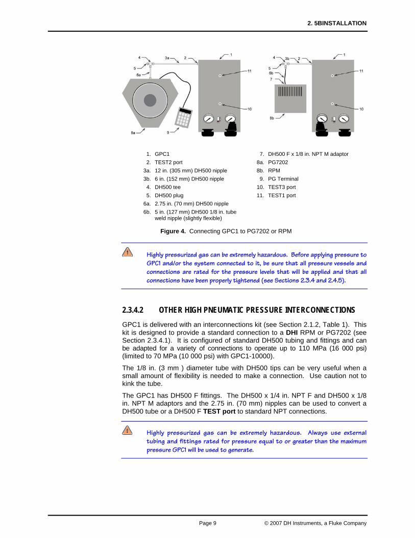
GPC1 is delivered with an interconnections kit (see Section 2.1.2, Table 1). This kit includes the high pressure hardware necessary to connect GPC1 to a DHI RPM or PG7202 and operate at pressure up to 110 MPa (16 000 psi) (limited to 70 MPa (10 000 psi) with GPC1-10000). See Figure 4 for the recommended layout and to identify the parts used from the interconnection kit. These setups assume that one (1) of the TEST ports on the top of GPC1 or an open leg of the interconnecting tee will be used to connect to the device or system under test. To convert a DH500 F to another fitting, install one (1) of the DH500 F x 1/8 in. NPT M or DH500 F x 1/4 in. NPT F adaptors on to one of the 2.75 in. (70 mm) DH500 nipples and install the nipple into the DH500 F port.
If the reference device is a PG7202, it should always be connected to the left, rear lateral TEST2 port.
2. 5BINSTALLATION
Page 9 © 2007 DH Instruments, a Fluke Company
1. GPC1 7. DH500 F x 1/8 in. NPT M adaptor2. TEST2 port 8a. PG7202
3a. 12 in. (305 mm) DH500 nipple 8b. RPM 3b. 6 in. (152 mm) DH500 nipple 9. PG Terminal
4. DH500 tee 10. TEST3 port 5. DH500 plug 11. TEST1 port
6a. 2.75 in. (70 mm) DH500 nipple 6b. 5 in. (127 mm) DH500 1/8 in. tube
weld nipple (slightly flexible)
Figure 4. Connecting GPC1 to PG7202 or RPM
Highly pressurized gas can be extremely hazardous. Before applying pressure to GPC1 and/or the system connected to it, be sure that all pressure vessels and connections are rated for the pressure levels that will be applied and that all connections have been properly tightened (see Sections 2.3.4 and 2.4.5).
2.3.4.2 OTHER HIGH PNEUMATIC PRESSURE INTERCONNECTIONS GPC1 is delivered with an interconnections kit (see Section 2.1.2, Table 1). This kit is designed to provide a standard connection to a DHI RPM or PG7202 (see Section 2.3.4.1). It is configured of standard DH500 tubing and fittings and can be adapted for a variety of connections to operate up to 110 MPa (16 000 psi) (limited to 70 MPa (10 000 psi) with GPC1-10000).
The 1/8 in. (3 mm ) diameter tube with DH500 tips can be very useful when a small amount of flexibility is needed to make a connection. Use caution not to kink the tube.
The GPC1 has DH500 F fittings. The DH500 x 1/4 in. NPT F and DH500 x 1/8 in. NPT M adaptors and the 2.75 in. (70 mm) nipples can be used to convert a DH500 tube or a DH500 F TEST port to standard NPT connections.
Highly pressurized gas can be extremely hazardous. Always use external tubing and fittings rated for pressure equal to or greater than the maximum pressure GPC1 will be used to generate.
GPC1-10000 / GPC1-16000™ OPERATION AND MAINTENANCE MANUAL
© 2007 DH Instruments, a Fluke Company Page 10
When planning system interconnections, consider that the time required to generate and stabilize a pressure is a direct function of the test volume and the mechanical stability of the test tubing and vessels. Always minimize volume to the extent possible and use thick walled, high pressure tubing and vessels.
DH500 F fittings are delivered with disposable, orange, plastic dummy plugs installed. These are NOT intended to hold high pressure. They should be removed and replaced with appropriate fittings or stainless steel plugs before high pressure operation. Each dummy plug carries a DH500 collar. Remove and retain the collar for use in connecting to the fitting.
2.3.4.3 RECOMMENDATIONS FOR TEST PORT CONNECTION, USE AND DUT CLEANLINESS CONSIDERATIONS
The interconnections kit supplied with the GPC1 includes hardware to adapt from a DH500 F TEST port to a 1/8 F or 1/4 in. M NPT fitting. To convert a DH500 F TEST port to one of these fittings, install either the DH500 F x 1/8 in. NPT M or DH500 F x 1/4 in. NPT F adaptors onto one of the 2.75 in. (70 mm) DH500 nipples and install the nipple into the DH500 F port.
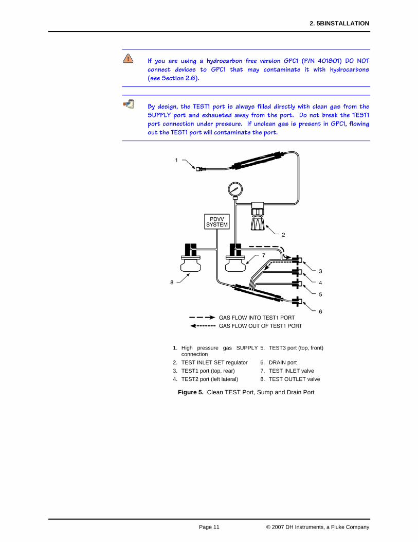
Special design features are included in GPC1 to avoid excessive contamination of GPC1 if liquids should return from the system to which it is connected. For this purpose, GPC1 is equipped with an inclined manifold that serves as a liquid sump (see Figure 5). A DRAIN port is provided at the low point so that the sump can be easily purged. The TEST ports all go directly through the sump so that any liquids returning from the system under test will collect there rather than being carried throughout GPC1. The top, rear TEST1 port is supplied directly from the SUPPLY port so that it is always filled with clean gas from the supply. Even if liquids are present in the sump, they will not enter the TEST1 port as gas that may have been exposed to liquids never flows into the port from GPC1 (see Figure 5).
Below are recommendations for use of the three (3) GPC1 TEST ports. If there is no risk of return of liquids from the devices that will be connected to GPC1, it is not necessary to discriminate TEST port usage.
• TEST1 port (top, rear): This port is supplied directly from the SUPPLY port and should be reserved for connecting devices that are known to be liquid free and must be protected from any risk of liquid contamination. If no such devices will be connected to GPC1, then this port may be used as any TEST port would.
• TEST2 port (left lateral): Normally, the reference in a calibration system, such as a PG7202 piston gauge or an RPM digital pressure monitor is connected here.
• TEST3 port (top, front): This port is connected to the lowest point on the drain and should be used for connecting test devices that may contain liquids.
2. 5BINSTALLATION
Page 11 © 2007 DH Instruments, a Fluke Company
If you are using a hydrocarbon free version GPC1 (P/N 401801) DO NOT connect devices to GPC1 that may contaminate it with hydrocarbons (see Section 2.6).
By design, the TEST1 port is always filled directly with clean gas from the SUPPLY port and exhausted away from the port. Do not break the TEST1 port connection under pressure. If unclean gas is present in GPC1, flowing out the TEST1 port will contaminate the port.
1. High pressure gas SUPPLYconnection
5. TEST3 port (top, front)
2. TEST INLET SET regulator 6. DRAIN port 3. TEST1 port (top, rear) 7. TEST INLET valve 4. TEST2 port (left lateral) 8. TEST OUTLET valve
Figure 5. Clean TEST Port, Sump and Drain Port
GPC1-10000 / GPC1-16000™ OPERATION AND MAINTENANCE MANUAL
© 2007 DH Instruments, a Fluke Company Page 12
2.4 POWER UP AND VERIFICATION
2.4.1 APPLY THE HIGH PRESSURE SUPPLY
This section assumes that the GPC1 system has already been set up, including pressure interconnection (see Section 2.3.1).
Proceed as follows (numerical references refer to Section 3.1, Figure 6):
Fully back off the TEST INLET SET regulator (5).
Close the TEST INLET valve (12).
Open the TEST OUTLET valve (15).
Apply the high pressure supply to the SUPPLY port (1).
Highly pressurized gas can be extremely hazardous. Before applying pressure to GPC1 and/or the system connected to it, be sure that all pressure vessels and connections are rated for the pressure levels that will be applied and that all connections have been properly tightened (see Section 2.4.5). Ensure that the GPC1 TEST INLET SET regulator is fully backed off and the INLET valve is closed (see Section 2.4.1).
2.4.2 ADJUST INLET PRESSURE
This section assumes that the GPC1 system has already been set up, including pressure interconnection (see Section 2.3.1).
Be sure the INLET valve is CLOSED before adjusting the TEST INLET SET regulator. If the INLET valve is open, the supply pressure will be admitted to GPC1 components and TEST ports.
Turn the TEST INLET SET regulator clockwise while observing the TEST INLET gauge. Set the pressure as indicated by the TEST INLET gauge to the desired maximum test pressure. The pressure set by the TEST INLET SET regulator is applied to the inlet of the INLET valve.
2.4.3 APPLY PDVV DRIVE PRESSURE
This section assumes that the GPC1 system has already been set up, including pressure interconnections (see Section 2.3).
Apply drive pressure to the PDVV DRIVE port. See Section 2.3.2, Table 2 to determine the necessary PDVV drive pressure value.
2. 5BINSTALLATION
Page 13 © 2007 DH Instruments, a Fluke Company
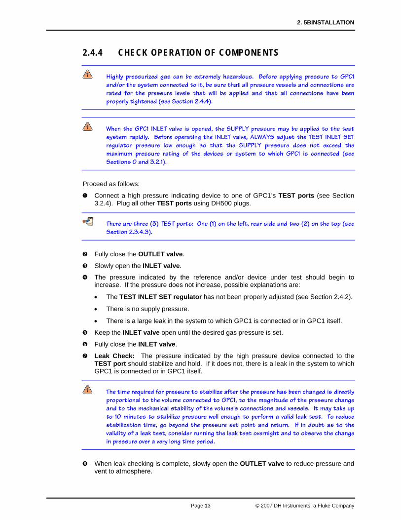
2.4.4 CHECK OPERATION OF COMPONENTS
Highly pressurized gas can be extremely hazardous. Before applying pressure to GPC1 and/or the system connected to it, be sure that all pressure vessels and connections are rated for the pressure levels that will be applied and that all connections have been properly tightened (see Section 2.4.4).
When the GPC1 INLET valve is opened, the SUPPLY pressure may be applied to the test system rapidly. Before operating the INLET valve, ALWAYS adjust the TEST INLET SET regulator pressure low enough so that the SUPPLY pressure does not exceed the maximum pressure rating of the devices or system to which GPC1 is connected (see Sections 0 and 3.2.1).
Proceed as follows:
Connect a high pressure indicating device to one of GPC1’s TEST ports (see Section 3.2.4). Plug all other TEST ports using DH500 plugs.
There are three (3) TEST ports: One (1) on the left, rear side and two (2) on the top (see Section 2.3.4.3).
Fully close the OUTLET valve.
Slowly open the INLET valve.
The pressure indicated by the reference and/or device under test should begin to increase. If the pressure does not increase, possible explanations are:
• The TEST INLET SET regulator has not been properly adjusted (see Section 2.4.2).
• There is no supply pressure.
• There is a large leak in the system to which GPC1 is connected or in GPC1 itself.
Keep the INLET valve open until the desired gas pressure is set.
Fully close the INLET valve.
Leak Check: The pressure indicated by the high pressure device connected to the TEST port should stabilize and hold. If it does not, there is a leak in the system to which GPC1 is connected or in GPC1 itself.
The time required for pressure to stabilize after the pressure has been changed is directly proportional to the volume connected to GPC1, to the magnitude of the pressure change and to the mechanical stability of the volume's connections and vessels. It may take up to 10 minutes to stabilize pressure well enough to perform a valid leak test. To reduce stabilization time, go beyond the pressure set point and return. If in doubt as to the validity of a leak test, consider running the leak test overnight and to observe the change in pressure over a very long time period.
When leak checking is complete, slowly open the OUTLET valve to reduce pressure and vent to atmosphere.
GPC1-10000 / GPC1-16000™ OPERATION AND MAINTENANCE MANUAL
© 2007 DH Instruments, a Fluke Company Page 14
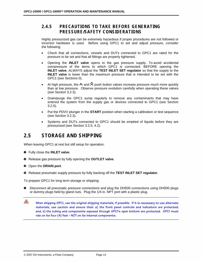
2.4.5 PRECAUTIONS TO TAKE BEFORE GENERATING PRESSURE/SAFETY CONSIDERATIONS
Highly pressurized gas can be extremely hazardous if proper procedures are not followed or incorrect hardware is used. Before using GPC1 to set and adjust pressure, consider the following:
• Check that all connections, vessels and DUTs connected to GPC1 are rated for the pressure to be set and that all fittings are properly tightened.
• Opening the INLET valve opens to the gas pressure supply. To avoid accidental overpressure of the items to which GPC1 is connected, BEFORE opening the INLET valve, ALWAYS adjust the TEST INLET SET regulator so that the supply to the INLET valve is lower than the maximum pressure that is intended to be set with the GPC1 (see Sections 0).
• At high pressure, the and push button valves increase pressure much more quickly than at low pressure. Observe pressure evolution carefully when operating these valves (see Section 3.2.3).
• Drain/purge the GPC1 sump regularly to remove any contaminants that may have entered the system from the supply gas or devices connected to GPC1 (see Section 3.2.5).
• Put the PDVV plunger in the START position when starting a calibration or test sequence (see Section 3.2.3).
• Systems and DUTs connected to GPC1 should be emptied of liquids before they are pressurized (see Section 3.2.5, 4.2).
2.5 STORAGE AND SHIPPING When leaving GPC1 at rest but still setup for operation:
Fully close the INLET valve.
Release gas pressure by fully opening the OUTLET valve.
Open the DRAIN port.
Release pneumatic supply pressure by fully backing off the TEST INLET SET regulator.
To prepare GPC1 for long term storage or shipping:
Disconnect all pneumatic pressure connections and plug the DH500 connections using DH500 plugs or dummy plugs held by gland nuts. Plug the 1/4 in. NPT port with a plastic plug.
When shipping GPC1, use the original shipping materials, if possible. If it is necessary to use alternate materials, use caution and ensure that: a) the front panel controls and indicators are protected; and, b) the tubing and components exposed through GPC1’s open bottom are protected. GPC1 must ride on its four (4) feet - NOT on its internal components.
2. 5BINSTALLATION
Page 15 © 2007 DH Instruments, a Fluke Company
2.6 SPECIAL CONSIDERATIONS FOR HYDROCARBON FREE OPERATION
A special “hydrocarbon free” version of GPC1 (P/N 401801 or P/N 402201) is available. This part number is delivered free of known sources of hydrocarbon in the GPC1 high pressure gas circuit. Of course, GPC1 will remain hydrocarbon free only so long as hydrocarbons are not introduced from an external source.
To maintain a hydrocarbon free GPC1, only connect devices to it that are known to be hydrocarbon free. If using a gas booster to supply the high pressure, the gas booster must be a hydrocarbon free version. If using a PG7202 piston gauge, the PG7202 must be a hydrocarbon free version and used with Krytox® lubricated piston-cylinder modules.

GPC1-10000 / GPC1-16000™ OPERATION AND MAINTENANCE MANUAL
© 2007 DH Instruments, a Fluke Company Page 16
NNOOTTEESS
3. OPERATION
Page 17 © 2007 DH Instruments, a Fluke Company
33.. OOPPEERRAATTIIOONN
3.1 OPERATING PRINCIPLE Numerical references in this section refer to Section 3.1, Figure 6.
GPC1 is a self-contained system designed to set and adjust gas pressure into static pressure test and calibration systems. GPC1-16000 operates from atmosphere (zero gauge) to 110 MPa (16 000 psi). GPC1-10000 operates to 70 MPa (10 000 psi). GPC1 combines the capability to execute large pressure changes very quickly with very fine pressure adjustment.
GPC1 uses two different techniques to set and adjust pressure. These are rough pressure control using the TEST INLET valve (12) and TEST OUTLET valve (15) and fine pressure control using the PDVV (+) (13) and (-) valves (14).
The first means of generating and adjusting pressure uses the external gas pressure supply (1) with the TEST INLET SET regulator (5), TEST INLET valve (12) and TEST OUTLET valve (15). This combination is used for filling the system under test, making large pressure changes and for rough pressure control. The valves are Belleville spring loaded, half-turn needle valves. Their operation is highly progressive over a half-turn with mechanical stops at each end so they cannot be over tightened. The regulator is self venting and its output is indicated by the TEST INLET gauge (4). The valve is turned clockwise (CW) to close and counter-clockwise (CCW) to open. A WHITE dot on the handle body indicates the valve’s current open/close position. The TEST INLET SET regulator (5) and TEST INLET gauge (4) are used to set the supply pressure to the TEST INLET valve (12). Opening the INLET valve (12) allows the supply pressure to enter GPC1 and reach the TEST ports (6,7,8). Opening the OUTLET valve (15) exhausts gas, reducing pressure in the system.
The second means of generating and adjusting pressure is the Pneumatically Driven Variable Volume (PDVV) (16) combined with the PDVV (+) (13) and (-) valves (14). This combination is used for smaller pressure changes and fine pressure control. The PDVV is a pneumatically actuated variable volume. A piston or plunger in a cylinder is exposed to the high pressure gas to be adjusted. The other end of the plunger is connected to a dome loaded pneumatic actuator. Changing the pneumatic pressure on the dome loaded actuator causes the plunger to move, increasing or decreasing the high gas pressure. A spring returns the plunger to its minimum stroke position when there is no pressure on the dome. A mechanical system tracks movement of the plunger and an indicator (18) displays the plunger position on the front panel. The PDVV (+) (13) and (-) valves (14) are momentary, poppet valves that open when pressed. The (+) valves (13) admit drive air pressure to the PDVV actuator causing the PDVV piston to move forward, compressing the high pressure gas and increasing the pressure. The (-) valves (14) have the opposite effect, causing pressure to decrease when they are operated.
GPC1-10000 / GPC1-16000™ OPERATION AND MAINTENANCE MANUAL
© 2007 DH Instruments, a Fluke Company Page 18
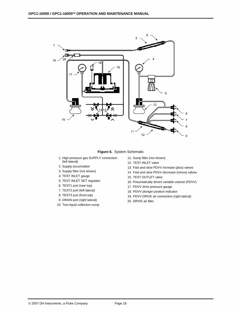
Figure 6. System Schematic
1. High pressure gas SUPPLY connection (left lateral)
2. Supply accumulator 3. Supply filter (not shown) 4. TEST INLET gauge 5. TEST INLET SET regulator 6. TEST1 port (rear top) 7. TEST2 port (left lateral) 8. TEST3 port (front top) 9. DRAIN port (right lateral)
10. Test liquid collection sump
11. Sump filter (not shown) 12. TEST INLET valve 13. Fast and slow PDVV increase (plus) valves 14. Fast and slow PDVV decrease (minus) valves 15. TEST OUTLET valve 16. Pneumatically driven variable volume (PDVV) 17. PDVV drive pressure gauge 18. PDVV plunger position indicator 19. PDVV DRIVE air connection (right lateral) 20. DRIVE air filter
3. 6BOPERATION
Page 19 © 2007 DH Instruments, a Fluke Company
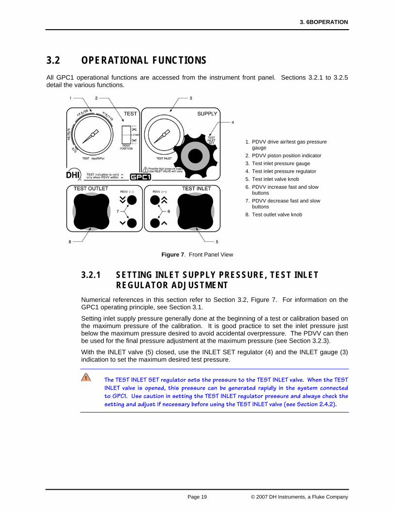
3.2 OPERATIONAL FUNCTIONS All GPC1 operational functions are accessed from the instrument front panel. Sections 3.2.1 to 3.2.5 detail the various functions.
Figure 7. Front Panel View
3.2.1 SETTING INLET SUPPLY PRESSURE, TEST INLET REGULATOR ADJUSTMENT
Numerical references in this section refer to Section 3.2, Figure 7. For information on the GPC1 operating principle, see Section 3.1.
Setting inlet supply pressure generally done at the beginning of a test or calibration based on the maximum pressure of the calibration. It is good practice to set the inlet pressure just below the maximum pressure desired to avoid accidental overpressure. The PDVV can then be used for the final pressure adjustment at the maximum pressure (see Section 3.2.3).
With the INLET valve (5) closed, use the INLET SET regulator (4) and the INLET gauge (3) indication to set the maximum desired test pressure.
The TEST INLET SET regulator sets the pressure to the TEST INLET valve. When the TEST INLET valve is opened, this pressure can be generated rapidly in the system connected to GPC1. Use caution in setting the TEST INLET regulator pressure and always check the setting and adjust if necessary before using the TEST INLET valve (see Section 2.4.2).
1. PDVV drive air/test gas pressure gauge
2. PDVV piston position indicator 3. Test inlet pressure gauge 4. Test inlet pressure regulator 5. Test inlet valve knob 6. PDVV increase fast and slow
buttons 7. PDVV decrease fast and slow
buttons 8. Test outlet valve knob
GPC1-10000 / GPC1-16000™ OPERATION AND MAINTENANCE MANUAL
© 2007 DH Instruments, a Fluke Company Page 20
3.2.2 ROUGH PRESSURE GENERATION/CONTROL, INLET AND OUTLET VALVE OPERATION
Numerical references in this section refer to Section 3.2, Figure 7. For information on the GPC1 operating principle, see Section 3.1.
The INLET valve (5) and OUTLET valve (8) are used to execute large pressure changes in the test system and for rough pressure control. The INLET valve is used to increase pressure and the OUTLET valve, decreases pressure and vents the system to atmosphere, setting zero gauge pressure. If finer pressure control, use the PDVV valves (see Section 3.2.3).
To increase pressure in the GPC1 system, open the INLET valve (5) slowly. Use the progressive nature of the valve to control the rate of pressure increase. Close the valve when the desired pressure has been reached. When a gas booster is used to supply high pressure, the booster may not be able to keep up with the flow rate needed to set the desired pressure. In this case, with the INLET valve open, wait for the booster to reach the desired pressure.
To decrease pressure in the GPC1 system, open OUTLET valve (8) slowly. Open the valve fully to vent the system to atmosphere (set zero gauge).
The TEST INLET valve connects the pressure supply to the test system. When the TEST INLET valve is opened, high pressure can be generated rapidly in the system connected to GPC1. Use caution in opening the TEST INLET valve and always check the TEST INLET pressure gauge before doing so (see Section 2.4.2).
3.2.3 FINE PRESSURE ADJUSTMENT, PDVV (+) AND (-) VALVE OPERATION
Numerical references in this section refer to Section 3.2, Figure 7 except where specified otherwise. For information on the GPC1 operating principle, see Section 3.1.
Use the valves labeled and to release gas from the PDVV actuator, causing the PDVV plunger to back off and pressure to decrease. Use the valves labeled are to admit gas to the PDVV actuator, causing the PDVV plunger to move forward and pressure to increase. The and valves are for high speed PDVV operation. The and valves are for slow speed PDVV operation.
The PDVV (+) (6) and (-) valves (7) are utilized to make small pressure changes and for fine pressure control. Brief momentary action on the and valves is used to bump or jog pressure in very small amounts around a pressure point.
If the PDVV plunger reaches end of stroke during a calibration or test, use the INLET valve (5) and/or OUTLET valve (8) to increase or decrease the pressure, as needed (see Section 3.2.2).
The actual rate of pressure change caused by the PDVV (+) valves and PDVV (-) valves is dependent on the test volume that is connected to GPC1 and the current pressure value. Increasing the test volume lowers the pressure change rate and pressure step size. Increasing the volume increases the rate and the pressure step size. The maximum pressure that can be generated by the PDVV (+) valves is dependent on the PDVV drive air supply (see Section 2.3.2, Table 2).
3. 6BOPERATION
Page 21 © 2007 DH Instruments, a Fluke Company
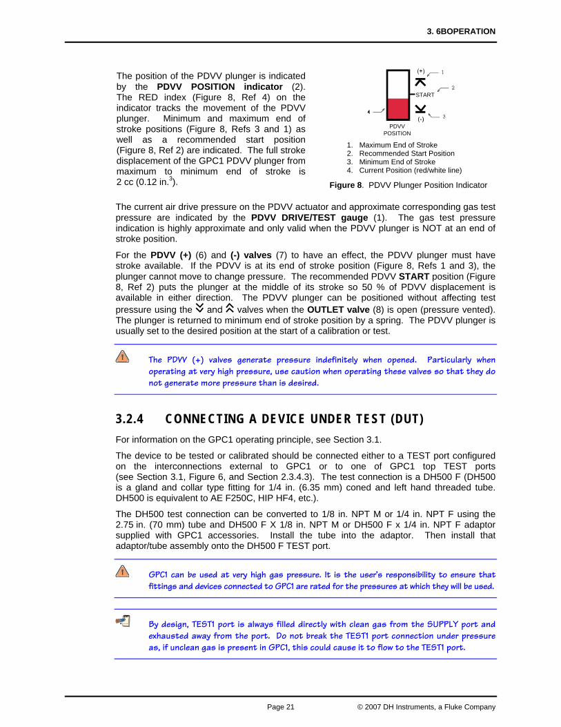
The position of the PDVV plunger is indicated by the PDVV POSITION indicator (2). The RED index (Figure 8, Ref 4) on the indicator tracks the movement of the PDVV plunger. Minimum and maximum end of stroke positions (Figure 8, Refs 3 and 1) as well as a recommended start position (Figure 8, Ref 2) are indicated. The full stroke displacement of the GPC1 PDVV plunger from maximum to minimum end of stroke is 2 cc (0.12 in.3).
PDVVPOSITION
START
1. Maximum End of Stroke 2. Recommended Start Position 3. Minimum End of Stroke 4. Current Position (red/white line)
Figure 8. PDVV Plunger Position Indicator
The current air drive pressure on the PDVV actuator and approximate corresponding gas test pressure are indicated by the PDVV DRIVE/TEST gauge (1). The gas test pressure indication is highly approximate and only valid when the PDVV plunger is NOT at an end of stroke position.
For the PDVV (+) (6) and (-) valves (7) to have an effect, the PDVV plunger must have stroke available. If the PDVV is at its end of stroke position (Figure 8, Refs 1 and 3), the plunger cannot move to change pressure. The recommended PDVV START position (Figure 8, Ref 2) puts the plunger at the middle of its stroke so 50 % of PDVV displacement is available in either direction. The PDVV plunger can be positioned without affecting test pressure using the and valves when the OUTLET valve (8) is open (pressure vented). The plunger is returned to minimum end of stroke position by a spring. The PDVV plunger is usually set to the desired position at the start of a calibration or test.
The PDVV (+) valves generate pressure indefinitely when opened. Particularly when operating at very high pressure, use caution when operating these valves so that they do not generate more pressure than is desired.
3.2.4 CONNECTING A DEVICE UNDER TEST (DUT) For information on the GPC1 operating principle, see Section 3.1.
The device to be tested or calibrated should be connected either to a TEST port configured on the interconnections external to GPC1 or to one of GPC1 top TEST ports (see Section 3.1, Figure 6, and Section 2.3.4.3). The test connection is a DH500 F (DH500 is a gland and collar type fitting for 1/4 in. (6.35 mm) coned and left hand threaded tube. DH500 is equivalent to AE F250C, HIP HF4, etc.).
The DH500 test connection can be converted to 1/8 in. NPT M or 1/4 in. NPT F using the 2.75 in. (70 mm) tube and DH500 F X 1/8 in. NPT M or DH500 F x 1/4 in. NPT F adaptor supplied with GPC1 accessories. Install the tube into the adaptor. Then install that adaptor/tube assembly onto the DH500 F TEST port.
GPC1 can be used at very high gas pressure. It is the user’s responsibility to ensure that fittings and devices connected to GPC1 are rated for the pressures at which they will be used.
By design, TEST1 port is always filled directly with clean gas from the SUPPLY port and exhausted away from the port. Do not break the TEST1 port connection under pressure as, if unclean gas is present in GPC1, this could cause it to flow to the TEST1 port.
GPC1-10000 / GPC1-16000™ OPERATION AND MAINTENANCE MANUAL
© 2007 DH Instruments, a Fluke Company Page 22
3.2.5 PURGING LIQUIDS FROM THE DUT/SYSTEM UNDER TEST GPC1 includes a sump to collect liquids that may return from the device or system under test to which it is connected. However, the amount of liquid that the sump can handle without liquids entering other GPC1 internal circuitry is limited. Excessive fluids in GPC1 and test connections can cause erratic pressure control and introduce unexpected uncertainty in measurements. DUTs and the system under test should be cleaned of liquids to the extent reasonably possible before being connected to GPC1. Also, see Section 2.3.4.3 for information about the appropriate GPC1 TEST port connection to use.
The procedure to purge the GPC1 sump and/or a DUT connected to GPC1 is:
Use GPC1 to pressurize the system, including the DUT, to approximately 3 500 kPa (500 psi) (or maximum pressure of the DUT if less than 3.5 MPa (500 psi)).
Open DRAIN port. Use the 5/8 in. open end wrench supplied in the GPC1 accessories to slowly and then more fully open the port allowing gas to exhaust as quickly as is safe and practical.
Observe whether the gas coming out of the DRAIN port contains liquid or liquid vapor.
Repeat steps through until there is no evidence of liquid in the gas escaping from the DRAIN port.
3.3 TYPICAL OPERATING SEQUENCE FOR A COMPLETE CALIBRATION OR TEST
GPC1 is most often used to set and adjust pressure to a reference measuring device and a DUT when performing a test or calibration. The reference measuring device may be a pressure monitor such as a digital indicator or a piston gauge or deadweight tester. The typical operational sequence is as follows:
Connect the DUT to the appropriate GPC1 TEST port or to a test port on the external system to which GPC1 is connected (see Sections 3.2.4, 2.3.4.3).
Set the TEST INLET SET regulator (see Section 3.2.1)
Position the PDVV plunger (see Section 3.2.3).
Purge the DUT (if necessary) (see Section 3.2 5).
Take the starting zero reading on the DUT: With the OUTLET valve open, and the INLET valve closed, the pressure in the test system is zero gauge.
Set ascending test pressures: Carefully open the INLET valve and control the gas input to set the pressure in the test system just under the desired test point (see Section 3.2.2). Pause a moment. Then use the PDVV (+)and/or (-) valves to adjust the pressure to the exact test pressure desired or, if the reference is a piston gauge, to float the piston gauge piston (see Section 3.2.3). Repeat this process for all of the ascending increments. If the increments are small enough for the PDVV displacement to generate the pressure, only the PDVV (+) valves may be needed to reach the next pressure. If the PDVV runs out of stroke, use the INLET valve to generate pressure and reposition the PDVV plunger.
Set descending test pressures: Very carefully open the OUTLET valve and control the gas exhaust to set pressure in the test system just over the desired test point (see Section 3.2.2). Then use the PDVV (+) and/or (-) valves to adjust the pressure to the exact test pressure desired or, if the reference is a piston gauge, to float the piston gauge piston (see Section 3.2.3). Repeat this process for all of the descending increments. If the increments are small enough for the PDVV displacement to generate the pressure, only the PDVV (-) valves may be needed to generate the next pressure. If the PDVV runs out of stroke, use the OUTLET valve to reduce pressure.
Vent the system and disconnect the DUT: Open the OUTLET valve fully and check that the DUT reads near zero. Disconnect the DUT.
4. 7BMAINTENANCE AND ADJUSTMENTS
Page 23 © 2007 DH Instruments, a Fluke Company
44.. MMAAIINNTTEENNAANNCCEE AANNDD
AADDJJUUSSTTMMEENNTTSS
4.1 OVERVIEW GPC1 was designed for maintenance free operation. The PDVV is permanently lubricated. No maintenance is required other than:
• Purge the sump very regularly (see Section 4.2).
• Clean/replace the PDVV drive air filter element when needed: The drive air filter may become contaminated and restrict the free flow of pressure. It should then be cleaned or replaced (see Section 4.3).
Maintenance and repair services for GPC1 are offered by DHI Authorized Service Providers (see Section 6.2, Table 4).
GPC1 is a sophisticated pressure setting and adjusting instrument with advanced features and functions. Before assuming that unexpected behavior is caused by a system defect or breakdown, use this manual and other training and troubleshooting facilities to become thoroughly familiar with GPC1 operation. For rapid troubleshooting assistance in specific situations, see Section 5.
GPC1 is covered by a limited 1 year warranty (see Section 6.2). Unauthorized service or repair during the warranty period is undertaken at the owner's risk and may cause damage that is NOT covered under product warranty and/or may void the product warranty.
GPC1-10000 / GPC1-16000™ OPERATION AND MAINTENANCE MANUAL
© 2007 DH Instruments, a Fluke Company Page 24
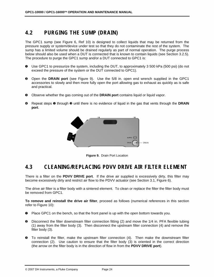
4.2 PURGING THE SUMP (DRAIN) The GPC1 sump (see Figure 6, Ref 10) is designed to collect liquids that may be returned from the pressure supply or system/device under test so that they do not contaminate the rest of the system. The sump has a limited volume should be drained regularly as part of normal operation. The purge process below should also be used when a DUT is connected that is known to contain liquids (see Section 3.2.5). The procedure to purge the GPC1 sump and/or a DUT connected to GPC1 is:
Use GPC1 to pressurize the system, including the DUT, to approximately 3 500 kPa (500 psi) (do not exceed the pressure of the system or the DUT connected to GPC1).
Open the DRAIN port (see Figure 9). Use the 5/8 in. open end wrench supplied in the GPC1 accessories to slowly and then more fully open the port allowing gas to exhaust as quickly as is safe and practical.
Observe whether the gas coming out of the DRAIN port contains liquid or liquid vapor.
Repeat steps through until there is no evidence of liquid in the gas that vents through the DRAIN port.
Figure 9. Drain Port Location
4.3 CLEANING/REPLACING PDVV DRIVE AIR FILTER ELEMENT There is a filter on the PDVV DRIVE port. If the drive air supplied is excessively dirty, this filter may become excessively dirty and restrict air flow to the PDVV actuator (see Section 3.1, Figure 6).
The drive air filter is a filter body with a sintered element. To clean or replace the filter the filter body must be removed from GPC1.
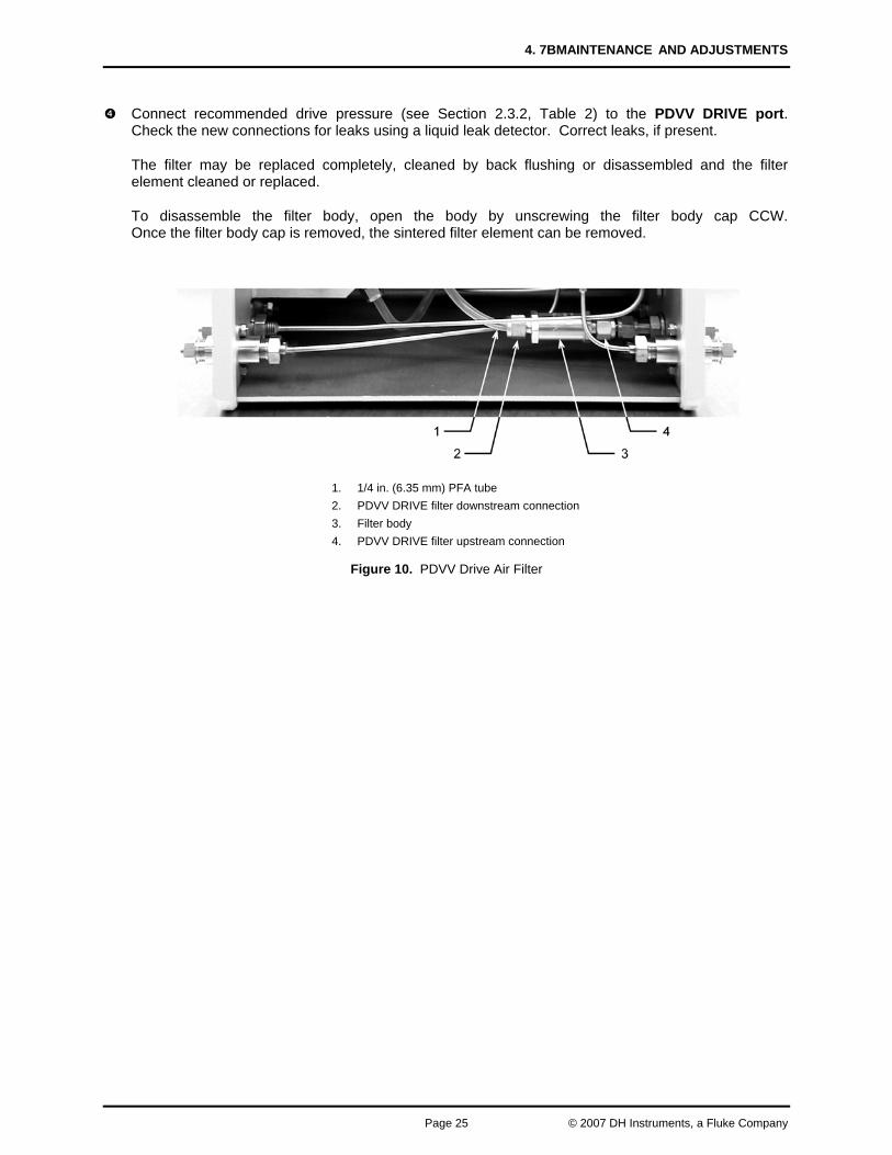
To remove and reinstall the drive air filter, proceed as follows (numerical references in this section refer to Figure 10):
Place GPC1 on the bench, so that the front panel is up with the open bottom towards you.
Disconnect the filter downstream filter connection fitting (2) and move the 1/4 in. PFA flexible tubing (1) away from the filter body (3). Then disconnect the upstream filter connection (4) and remove the filter body (3).
To reinstall the filter, make the upstream filter connection (4). Then make the downstream filter connection (2). Use caution to ensure that the filter body (3) is oriented in the correct direction (the arrow on the filter body is in the direction of flow in from the PDVV DRIVE port).
4. 7BMAINTENANCE AND ADJUSTMENTS
Page 25 © 2007 DH Instruments, a Fluke Company
Connect recommended drive pressure (see Section 2.3.2, Table 2) to the PDVV DRIVE port. Check the new connections for leaks using a liquid leak detector. Correct leaks, if present.
The filter may be replaced completely, cleaned by back flushing or disassembled and the filter element cleaned or replaced.
To disassemble the filter body, open the body by unscrewing the filter body cap CCW. Once the filter body cap is removed, the sintered filter element can be removed.
1. 1/4 in. (6.35 mm) PFA tube 2. PDVV DRIVE filter downstream connection 3. Filter body 4. PDVV DRIVE filter upstream connection
Figure 10. PDVV Drive Air Filter

GPC1-10000 / GPC1-16000™ OPERATION AND MAINTENANCE MANUAL
© 2007 DH Instruments, a Fluke Company Page 26
NNOOTTEESS
5. TROUBLESHOOTING
Page 27 © 2007 DH Instruments, a Fluke Company
55.. TTRROOUUBBLLEESSHHOOOOTTIINNGG
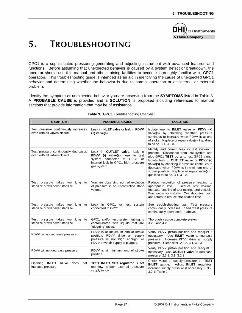
GPC1 is a sophisticated pressuring generating and adjusting instrument with advanced features and functions. Before assuming that unexpected behavior is caused by a system defect or breakdown, the operator should use this manual and other training facilities to become thoroughly familiar with GPC1 operation. This troubleshooting guide is intended as an aid in identifying the cause of unexpected GPC1 behavior and determining whether the behavior is due to normal operation or an internal or external problem.
Identify the symptom or unexpected behavior you are observing from the SYMPTOMS listed in Table 3. A PROBABLE CAUSE is provided and a SOLUTION is proposed including references to manual sections that provide information that may be of assistance.
Table 3. GPC1 Troubleshooting Checklist
SYMPTOM PROBABLE CAUSE SOLUTION
Test pressure continuously increases even with all valves closed.
Leak in INLET valve or leak in PDVV (+) valve(s).
Isolate leak to INLET valve or PDVV (+) valve(s) by checking whether pressure continues to increase when PDVV is at end of stoke. Replace or repair valve(s) if qualified to do so. 3.1, 3.2.3.
Test pressure continuously decreases even with all valves closed.
Leak in OUTLET valve, leak in PDVV (-) valve(s), leak in test system connected to GPC1 or internal leak in GPC1 high pressure gas system.
Identify and correct leak in test system if present. Disconnect from test system and plug GPC1 TEST ports to test GPC1 alone. Isolate leak to OUTLET valve or PDVV (-) valve(s) by checking if pressure continues to decrease when PDVV is in minimum end of stroke position. Replace or repair valve(s) if qualified to do so. 3.1, 3.2.3.
Test pressure takes too long to stabilize or will never stabilize.
You are observing normal evolution of pressure in an uncontrolled static volume.
Reduce resolution of pressure reading to appropriate level. Reduce test volume. Increase stability of test tubings and vessels. Wait longer for stability. Overshoot test point and return to reduce stabilization time.
Test pressure takes too long to stabilize or will never stabilize.
Leak in GPC1 or test system connected to GPC1.
See troubleshooting tips “Test pressure continuously increases…” and “Test pressure continuously decreases…” above.
Test pressure takes too long to stabilize or will never stabilize.
GPC1 and/or test system tubing is contaminated with liquids that are “plugging” tubes.
Thoroughly purge complete system. 3.2.5 and 4.2
PDVV will not increase pressure. PDVV is at maximum end of stroke position, PDVV drive air supply pressure is not high enough, or PDVV drive air supply is plugged.
Verify PDVV piston position and readjust if necessary. Use INLET valve to increase pressure. Increase PDVV drive air supply pressure. Clean filter. 2.3.2, 3.1, 3.2.3
PDVV will not decrease pressure. PDVV is at minimum end of stroke position.
Verify PDVV piston position and readjust if necessary. Use OUTLET valve to decrease pressure. 2.3.2, 3.1, 3.2.3
Opening INLET valve does not increase pressure.
TEST INLET SET regulator is set too low and/or external pressure supply to low.
Check value of supply pressure on TEST INLET gauge. Adjust INLET regulator, increase supply pressure if necessary. 2.3.2, 3.2.1, Table 2
GPC1-10000 / GPC1-16000™ OPERATION AND MAINTENANCE MANUAL
© 2007 DH Instruments, a Fluke Company Page 28
NNOOTTEESS
6. APPENDICES
Page 29 © 2007 DH Instruments, a Fluke Company
66.. AAPPPPEENNDDIICCEESS
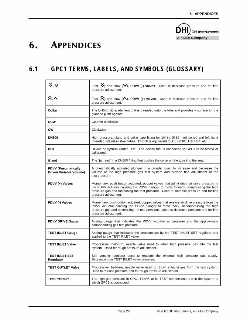
6.1 GPC1 TERMS, LABELS, AND SYMBOLS (GLOSSARY)
, Fast ( ) and slow ( ), PDVV (-) valves. Used to decrease pressure and for finepressure adjustment.
, Fast ( ) and slow ( ), PDVV (+) valves. Used to increase pressure and for fine pressure adjustment.
Collar The DH500 fitting element that is threaded onto the tube and provides a surface for the gland to push against.
CCW Counter-clockwise
CW Clockwise
DH500 High pressure, gland and collar type fitting for 1/4 in. (6.35 mm) coned and left hand threaded, stainless steel tubes. DH500 is equivalent to AE F250C, HIP HF4, etc.
DUT Device or System Under Test. The device that is connected to GPC1 to be tested or calibrated.
Gland The “jam nut” in a DH500 fitting that pushes the collar on the tube into the seat.
PDVV (Pneumatically Driven Variable Volume)
A pneumatically actuated plunger in a cylinder used to increase and decrease the volume of the high pressure gas test system and provide fine adjustment of the test pressure.
PDVV (+) Valves Momentary, push button actuated, poppet valves that admit drive air drive pressure to the PDVV actuator causing the PDVV plunger to move forward, compressing the high pressure gas and increasing the test pressure. Used to increase pressure and for fine pressure adjustment.
PDVV (-) Valves Momentary, push button actuated, poppet valves that release air drive pressure from the PDVV actuator causing the PDVV plunger to move back, decompressing the high pressure gas and decreasing the test pressure. Used to decrease pressure and for fine pressure adjustment.
PDVV DRIVE Gauge Analog gauge that indicates the PDVV actuator air pressure and the approximate corresponding gas test pressure.
TEST INLET Gauge Analog gauge that indicates the pressure set by the TEST INLET SET regulator and applied to the TEST INLET valve.
TEST INLET Valve Progressive, half-turn, needle valve used to admit high pressure gas into the test system. Used for rough pressure adjustment.
TEST INLET SET Regulator
Self venting regulator used to regulate the external high pressure gas supply. Sets maximum TEST INLET valve pressure.
TEST OUTLET Valve Progressive, half-turn, needle valve used to return exhaust gas from the test system. Used to release pressure and for rough pressure adjustment.
Test Pressure The high gas pressure in GPC1 PDVV, at its TEST connections and in the system to which GPC1 is connected.
GPC1-10000 / GPC1-16000™ OPERATION AND MAINTENANCE MANUAL
© 2007 DH Instruments, a Fluke Company Page 30
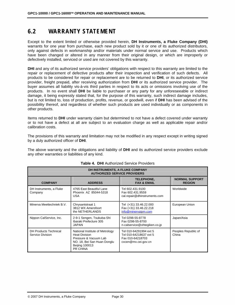
6.2 WARRANTY STATEMENT Except to the extent limited or otherwise provided herein, DH Instruments, a Fluke Company (DHI) warrants for one year from purchase, each new product sold by it or one of its authorized distributors, only against defects in workmanship and/or materials under normal service and use. Products which have been changed or altered in any manner from their original design, or which are improperly or defectively installed, serviced or used are not covered by this warranty.
DHI and any of its authorized service providers’ obligations with respect to this warranty are limited to the repair or replacement of defective products after their inspection and verification of such defects. All products to be considered for repair or replacement are to be returned to DHI, or its authorized service provider, freight prepaid, after receiving authorization from DHI or its authorized service provider. The buyer assumes all liability vis-à-vis third parties in respect to its acts or omissions involving use of the products. In no event shall DHI be liable to purchaser or any party for any unforeseeable or indirect damage, it being expressly stated that, for the purpose of this warranty, such indirect damage includes, but is not limited to, loss of production, profits, revenue, or goodwill, even if DHI has been advised of the possibility thereof, and regardless of whether such products are used individually or as components in other products.
Items returned to DHI under warranty claim but determined to not have a defect covered under warranty or to not have a defect at all are subject to an evaluation charge as well as applicable repair and/or calibration costs.
The provisions of this warranty and limitation may not be modified in any respect except in writing signed by a duly authorized officer of DHI.
The above warranty and the obligations and liability of DHI and its authorized service providers exclude any other warranties or liabilities of any kind.
Table 4. DHI Authorized Service Providers DH INSTRUMENTS, A FLUKE COMPANY
AUTHORIZED SERVICE PROVIDERS
COMPANY
ADDRESS
TELEPHONE, FAX & EMAIL
NORMAL SUPPORT REGION
DH Instruments, a Fluke Company
4765 East Beautiful Lane Phoenix AZ 85044-5318 USA
Tel 602.431.9100 Fax 602.431.9559 [email protected]
Worldwide
Minerva Meettechniek B.V. Chrysantstraat 1 3812 WX Amersfoort the NETHERLANDS
Tel (+31) 33.46.22.000 Fax (+31) 33.46.22.218 [email protected]
European Union
Nippon CalService, Inc. 2-9-1 Sengen, Tsukuba-Shi Ibaraki Prefecture 305 JAPAN
Tel 0298-55-8778 Fax 0298-55-8700 [email protected]
Japan/Asia
DH Products Technical Service Division
National Institute of Metrology Heat Division Pressure & Vacuum Lab NO. 18, Bei San Huan Donglu Beijing 100013 PR CHINA
Tel 010-64291994 ext 5 Tel 010-64218637 ext 5 Fax 010-64218703 [email protected]
Peoples Republic of China