Embed Size (px)
Citation preview
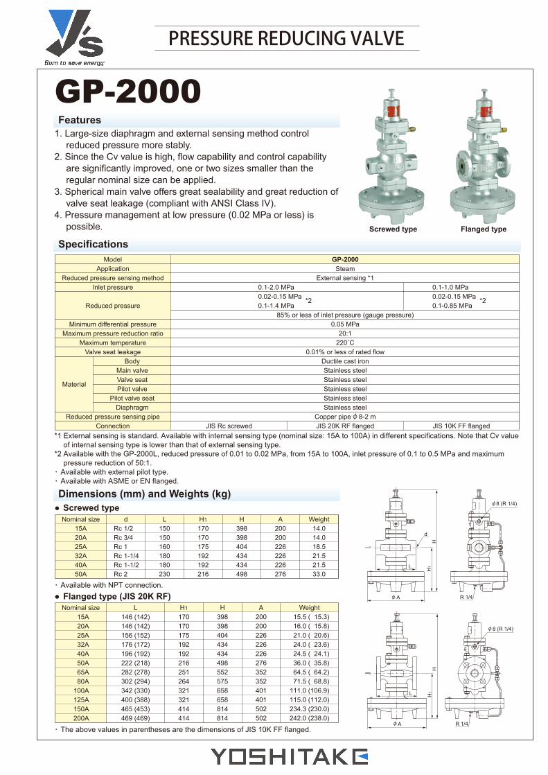
PRESSURE REDUCING VALVE
GP-2000Features
1. Large-size diaphragm and external sensing method controlreduced pressure more stably.
2. Since the Cv value is high, flow capability and control capabilityare significantly improved, one or two sizes smaller than theregular nominal size can be applied.
3. Spherical main valve offers great sealability and great reduction ofvalve seat leakage (compliant with ANSI Class IV).
4. Pressure management at low pressure (0.02 MPa or less) ispossible.
Specifications
Dimensions (mm) and Weights (kg)
Nominal size15A20A25A32A40A50A
dRc 1/2Rc 3/4Rc 1Rc 1-1/4Rc 1-1/2Rc 2
L150150160180180230
H1
170170175192192216
H398398404434434498
A200200226226226276
Weight14.014.018.521.521.533.0
Nominal size15A20A25A32A40A50A65A80A
100A125A150A200A
L146 (142)146 (142)156 (152)176 (172)196 (192)222 (218)282 (278)302 (294)342 (330)400 (388)465 (453)469 (469)
H1
170170175192192216251264321321414414
H398398404434434498552575658658814814
A200200226226226276352352401401502502
Weight 15.5 ( 15.3) 16.0 ( 15.8) 21.0 ( 20.6) 24.0 ( 23.6) 24.5 ( 24.1) 36.0 ( 35.8) 64.5 ( 64.2) 71.5 ( 68.8)111.0 (106.9)115.0 (112.0)234.3 (230.0)242.0 (238.0)
Screwed type Flanged type
*1 External sensing is standard. Available with internal sensing type (nominal size: 15A to 100A) in different specifications. Note that Cv valueof internal sensing type is lower than that of external sensing type.
*2 Available with the GP-2000L, reduced pressure of 0.01 to 0.02 MPa, from 15A to 100A, inlet pressure of 0.1 to 0.5 MPa and maximumpressure reduction of 50:1.
・ Available with external pilot type.・ Available with ASME or EN flanged.
GP-2000Steam
External sensing *1
85% or less of inlet pressure (gauge pressure)0.05 MPa
20:1220˚C
0.01% or less of rated flowDuctile cast ironStainless steelStainless steelStainless steelStainless steelStainless steel
Copper pipe 8-2 mJIS 20K RF flanged
ModelApplication
Reduced pressure sensing methodInlet pressure
Reduced pressure
Minimum differential pressureMaximum pressure reduction ratio
Maximum temperatureValve seat leakage
BodyMain valveValve seatPilot valve
Pilot valve seatDiaphragm
Reduced pressure sensing pipeConnection
Material
JIS Rc screwed JIS 10K FF flanged
0.1-2.0 MPa0.02-0.15 MPa *20.1-1.4 MPa
0.1-1.0 MPa0.02-0.15 MPa *20.1-0.85 MPa
● Screwed type
・ Available with NPT connection.
・ The above values in parentheses are the dimensions of JIS 10K FF flanged.
● Flanged type (JIS 20K RF) R 1/4
8 (R 1/4)
d
A
L H1
H
R 1/4
8 (R 1/4)
A
L H1
H
φ
φ
φ
φ
φ
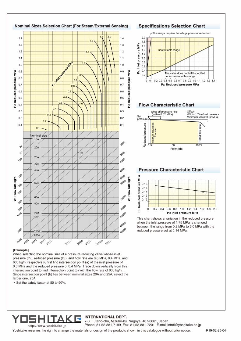
Nominal Sizes Selection Chart (For Steam/External Sensing)
2.01.81.61.41.21.00.80.60.40.2
0 0.2 0.3 0.4 0.5 0.6 0.7 0.8 0.9 1.0 1.1 1.2 1.3 1.40.1
This range requires two-stage pressure reduction.
Controllable range
The valve does not fulfill specified performance in this range.
P1: I
nlet
pre
ssur
e M
Pa
P2: Reduced pressure MPa
[Example]When selecting the nominal size of a pressure reducing valve whose inletpressure (P1), reduced pressure (P2), and flow rate are 0.6 MPa, 0.4 MPa, and600 kg/h, respectively, first find intersection point (a) of the inlet pressure of 0.6 MPa and the reduced pressure of 0.4 MPa. Trace down vertically from thisintersection point to find intersection point (b) with the flow rate of 600 kg/h.Since intersection point (b) lies between nominal sizes 20A and 25A, select thelarger one, 25A.・Set the safety factor at 80 to 90%.
60
80
100
200
300
400
600
800
1000
2000
30004000
60008000
1000020000
3000040000
6000080000
8000060000
4000030000
20000
100008000
6000
40003000
2000
1.4
1.3
1.2
1.1
1.0
0.9
0.8
0.7
0.6
0.5
0.4
0.3
0.2
0.1
1.4
1.3
1.2
1.1
1.0
0.9
0.8
0.7
0.6
0.5
0.4
0.3
0.2
0.1
(b)
(a)
15A
20A
25A
32A
40A
50A
65A
80A
100A125A
150A200A
2.01.81.6
1.0
0.9
1.4
1.2
0.8
0.7
0.6
0.5
0.4
0.3
0.2
0.1
Nominal size
P2:
Red
uced
pre
ssur
e M
PaW
: Flo
w ra
te k
g/h
P 2: R
educ
ed p
ress
ure
MPa
W: F
low
rate
kg/
h
P1: Inl
et pr
essu
re M
Pa
Specifications Selection Chart
0 5 50 100%
Setpressure
Shut-off pressure rise (within 0.02 MPa)
Red
uced
pre
ssur
e
Min
imum
adj
usta
ble
flow
rate
Rat
ed fl
ow ra
te
Flow rate
OffsetWithin 10% of set pressure Minimum value: 0.02 MPa
0.160.150.140.130.12
0 0.2 0.4 0.6 0.8 1.0 1.2 1.4 1.6 1.8 2.0
P2: R
educ
ed p
ress
ure
MPa
P1: Inlet pressure MPa
This chart shows a variation in the reduced pressurewhen the inlet pressure of 1.75 MPa is changedbetween the range from 0.2 MPa to 2.0 MPa with thereduced pressure set at 0.14 MPa.
Flow Characteristic Chart
Pressure Characteristic Chart
P19-02-25-04

![Larbert High School Faculty of Mathematics24453]Higher_Past...2009 P1 Q15 2009 P1 Q21 2010 P1 Q1 2010 P1 Q8 2010 P1 Q21 2010 P1 Q23 2011 P1 Q2 2011 P1 Q8 2011 P1 Q21 2012 P1 Q4 2012](https://img.pdfslide.us/doc/110x75/60bd9bf2b65aaa2b316d3bc9/larbert-high-school-faculty-of-mathematics-24453higherpast-2009-p1-q15-2009.jpg)