Embed Size (px)
Citation preview

GOVERNMENT POLYTECHNIC, PUNE
CERTIFICATE
This is certify that Ashwin Tumma, Enrollment No.
0506039, Third Year Diploma in Computer Engineering has
successfully completed his Seminar Report on the topic
BLUE EYES
HUMAN OPERATOR MONITORING SYSTEM.
as a part of his Diploma Curriculum in the academic year
2007-08.
Date : 6th October,2007
Seminar Guide Head of Dept. Principal
(Prof. U. V. Kokate) (Prof. U. V. Kokate) (Prof. C. R. Joshi)
2
ACKNOWLEDGEMENTS
I take this opportunity to express my profound gratitude to my
Project and Seminar guide Prof. U. V. Kokate Sir, for all the valuable
guidance and support that he rendered.
Sir also guided through the essence of time management,
need of efficient organizing, presentation skills criterion in seminar and
designing of a product from the user’s perspective. This assisted me to
be more selective in presentations.
Over the weeks, the Staff of Computer Engineering Department,
has also provided significant encouragement and extended their
invigorous support. I also thank them for their invaluable guidance.
Tumma Ashwin K.
(0506039)
Third Year Computer
3
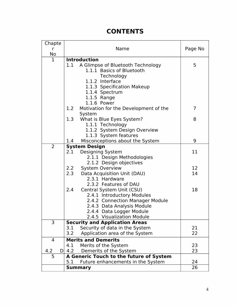
CONTENTS
Chapter
NoName Page No
1 Introduction1.1 A Glimpse of Bluetooth Technology 1.1.1 Basics of Bluetooth Technology 1.1.2 Interface 1.1.3 Specification Makeup 1.1.4 Spectrum 1.1.5 Range 1.1.6 Power1.2 Motivation for the Development of the System1.3 What is Blue Eyes System? 1.1.1 Technology 1.1.2 System Design Overview 1.1.3 System features 1.4 Misconceptions about the System
5
7
8
92 System Design
2.1 Designing System 2.1.1 Design Methodologies 2.1.2 Design objectives2.2 System Overview2.3 Data Acquisition Unit (DAU) 2.3.1 Hardware 2.3.2 Features of DAU2.4 Central System Unit (CSU) 2.4.1 Introductory Modules 2.4.2 Connection Manager Module 2.4.3 Data Analysis Module 2.4.4 Data Logger Module 2.4.5 Visualization Module
11
1214
18
3 Security and Application Areas3.1 Security of data in the System3.2 Application area of the System
2122
4 Merits and Demerits4.1 Merits of the System
4.2 D 4.2 Demerits of the System 2323
5 A Generic Touch to the future of System5.1 Future enhancements in the System 24Summary 26
4

Bibliography 27
5
CHAPTER 1: INTRODUCTION
1.1 A GLIMPSE OF THE BLUETOOTH TECHNOLOGY
1.1.1 Basics of Bluetooth
Bluetooth wireless technology is a short-range
communications technology intended to replace the cables connecting
portable and/or fixed devices while maintaining high levels of security.
The key features of Bluetooth technology are robustness, low power,
and low cost. The Bluetooth specification defines a uniform structure
for a wide range of devices to connect and communicate with each
other.
Bluetooth technology has achieved global acceptance such
that any Bluetooth enabled device, almost everywhere in the world,
can connect to other Bluetooth enabled devices in proximity. Bluetooth
enabled electronic devices connect and communicate wirelessly
through short-range, ad hoc networks known as piconets. Each device
can simultaneously communicate with up to seven other devices within
a single piconet. Each device can also belong to several piconets
simultaneously. Piconets are established dynamically and
automatically as Bluetooth enabled devices enter and leave radio
proximity.
A fundamental Bluetooth wireless technology strength is
the ability to simultaneously handle both data and voice transmissions.
This enables users to enjoy variety of innovative solutions such as a
hands-free headset for voice calls, printing and fax capabilities, and
6
synchronizing PDA, laptop, and mobile phone applications to name a
few.
1.1.2 Interface
Bluetooth technology’s adaptive frequency hopping (AFH)
capability was designed to reduce interference between wireless
technologies sharing the 2.4 GHz spectrum. AFH works within the
spectrum to take advantage of the available frequency. This is done by
detecting other devices in the spectrum and avoiding the frequencies
they are using. This adaptive hopping allows for more efficient
transmission within the spectrum, providing users with greater
performance even if using other technologies along with Bluetooth
technology.
1.1.3 Specification Make-up
Unlike many other wireless standards, the Bluetooth
wireless specification gives product developers both link layer and
application layer definitions, which supports data and voice
applications.
1.1.4 Spectrum
Bluetooth technology operates in the unlicensed industrial,
scientific and medical (ISM) band at 2.4 to 2.485 GHz, using a spread
spectrum, frequency hopping, full-duplex signal at a nominal rate of
1600 hops/sec.
1.1.5 Range
7
The operating range depends on the device class:
Class 3 radios – have a range of up to 1 meter or 3 feet
Class 2 radios – most commonly found in mobile devices – have a
range of 10 meters or 30 feet
Class 1 radios – used primarily in industrial use cases – have a range of
100 meters or 300 feet
1.1.6 Power
The most commonly used radio is Class 2 and uses 2.5 mW
of power. Bluetooth technology is designed to have very low power
consumption. This is reinforced in the specification by allowing radios
to be powered down when inactive.
1.2MOTIVATION FOR THE DEVELOPMENT OF THE
SYSTEM
Human error is still one of the most frequent causes of
catastrophes and ecological disasters. The main reason is that the
monitoring systems concern only the state of the processes whereas
human contribution to the overall performance of the system is left
unsupervised. The control instruments are automated to a large
extent, so a human–operator becomes a passive observer of the
supervised system, which results in weariness and vigilance drop.
Thus, he may not notice important changes of indications causing
financial or ecological consequences and a threat to human life. It
therefore is crucial to assure that the operator’s conscious brain is
involved in an active system supervising over the whole work time
period.
8
It is possible to measure indirectly the level of the
operator’s conscious brain involvement using eye motility analysis.
Although there are capable sensors available on the market, a complex
solution enabling transformation, analysis and reasoning based on
measured signals still does not exist. In large control rooms, wiring the
operator to the central system is a serious limitation of his mobility and
disables his operation. Utilization of wireless technology becomes
essential.
1.3 WHAT IS BLUE EYES SYSTEM?
1.3.1 Technology
The system developed is intended to be the complex
solution for monitoring and recording the operator’s conscious brain
involvement as well as his physiological condition. For this designing a
Personal Area Network is required linking all the operators and the
supervising system. As the operator using his sight and hearing senses
the state of the controlled system, the supervising system will look
after his physiological condition.
1.3.2 System design overview
The system consists of a portable measuring unit and a
central analytical system. The mobile device is integrated with
Bluetooth module providing wireless interface between the operator-
worn sensors called the Data Acquisition Unit (DAU) and the central
unit called the Central System Unit (CSU). ID cards assigned to each of
the operators and adequate user profiles on the central unit side
provide necessary data personalization so that different people can
use a single sensor.
9
Why the name BlueEyes?
The main thing is to explain the name of the system.
BlueEyes emphasizes the foundations of the project – Bluetooth
technology and the movements of the eyes. Bluetooth provides
reliable wireless communication whereas the eye movements enable
us to obtain a lot of interesting and important information.
1.3.3 System features
BlueEyes system provides technical means for monitoring
and recording human-operator's physiological condition. The key
features of the system are:
• visual attention monitoring (eye motility analysis)
• physiological condition monitoring (pulse rate, blood
oxygenation)
• operator's position detection (standing, lying)
• wireless data acquisition using Bluetooth technology
• real-time user-defined alarm triggering
• physiological data, operator's voice and overall view of the
control room recording
• recorded data playback
1.4MISCONCEPTIONS ABOUT THE BLUE EYES SYSTEM
Knowing what the Blue Eyes System actually is, it is
obvious that there arise many misconceptions about the Blue Eye
System in the user’s or the operators mind. Here’s an attempt to clear
some of the misconceptions about the System.
10
The Blue Eyes System does not predict or interpret with
the operator’s thoughts. Rather it is designed just to monitor the
physiological condition of the operator. The system interprets with the
operator’s state of brain with the help of eye motility analysis, on the
contrary the thoughts of the operator are been initiated in the mind of
the operator. So, there arises no concept of the system interpreting the
operator’s thoughts.
Also the second misconception that arises is that, Is this
system able to compel or force the operator to work? No! The Blue
Eyes system cannot force the operator directly to work with the
desired system or carry out specific tasks that are assigned to him. It is
the duty of the system administrator to monitor the operator, and then
to take appropriate measures for the irregularity of the operator, when
such a kind of system is employed in a Personal Area Network.
11

12
CHAPTER 2: SYSTEM DESIGN
2.1 DESIGNING SYSTEM
2.1.1Design Methodologies
In creating the Blue Eyes system a waterfall software
development model is used since it is suitable for unrepeatable and
explorative projects. During the course of the development UML
standard notations are used. They facilitate communication between
team members; all the ideas are clearly expressed by means of various
diagrams, which is a sound base for further development.
The results of the functional design phase were
documented on use case diagrams. During the low-level design stage
the whole system is divided into modules. Each of them has an
independent, well-defined functional interface providing precise
description of the services offered to the other modules. All the
interfaces are documented on UML class-, interaction- and state
diagrams. At this point each of the modules can be assigned to a team
member, implemented and tested in parallel. The last stage of the
project is the integrated system testing.
2.1.2Design Objectives
If such a system is to be practically or commercially
implemented into practice then the following criterions should be taken
care of when the system is designed to be served in a particular
context.
• A mobile Data Acquisition device should be configured upon a
legitimate operator of the system. The range and connections of
the two communicating Bluetooth modules should also be taken
into consideration.
13
• A reliable time-buffering, processing and recording mechanism
should be configured at the right location and it should also fall
within the range of the Bluetooth transmitting device so that it
can receive the signals and data at the optimal level.
• A clear visualization interface is to be maintained in the Central
System Unit of the system for the graphical or a visual display of
all the activities that are being monitored by the system. A visual
representation of the physiological activities also helps the
supervisor of the system to reconstruct the course of the
selected operator’s duty.
• There should also be a mechanism for the customary analysation
of the data that is received by the Bluetooth module.
• The system design implementation should also ensure a
possibility of distributing the processing among a number of
computers. i. e. the data operator’s data are to be recorded by
separate instances of the Data logger and then further passed on
to the processing to a distributed processing network, so as to
speed up the processing and also for accomplishment of
distributed database processing.
2.2 SYSTEM OVERVIEW
BlueEyes system provides technical means for monitoring
and recording the operator’s basic physiological parameters. The most
important parameter is saccadic activity, which enables the system to
monitor the status of the operator’s visual attention along with head
acceleration, which accompanies large displacement of the visual axis.
Complex industrial environment can create a danger of exposing the
operator to toxic substances, which can affect his cardiac, circulatory
and pulmonary systems. Thus, on the grounds of plethysmographic
14
signal taken from the forehead skin surface, the system computes
heart beat rate and blood oxygenation.
The BlueEyes system checks above parameters against
abnormal (e.g. a low level of blood oxygenation or a high pulse rate) or
undesirable (e.g. a longer period of lowered visual attention) values
and triggers user-defined alarms when necessary.
Quite often in an emergency situation operators speak to
themselves expressing their surprise or stating verbally the problem.
Therefore, the operator’s voice, physiological parameters and an
overall view of the operating room are recorded. This helps to
reconstruct the course of operators’ work and provides data for long-
term analysis.
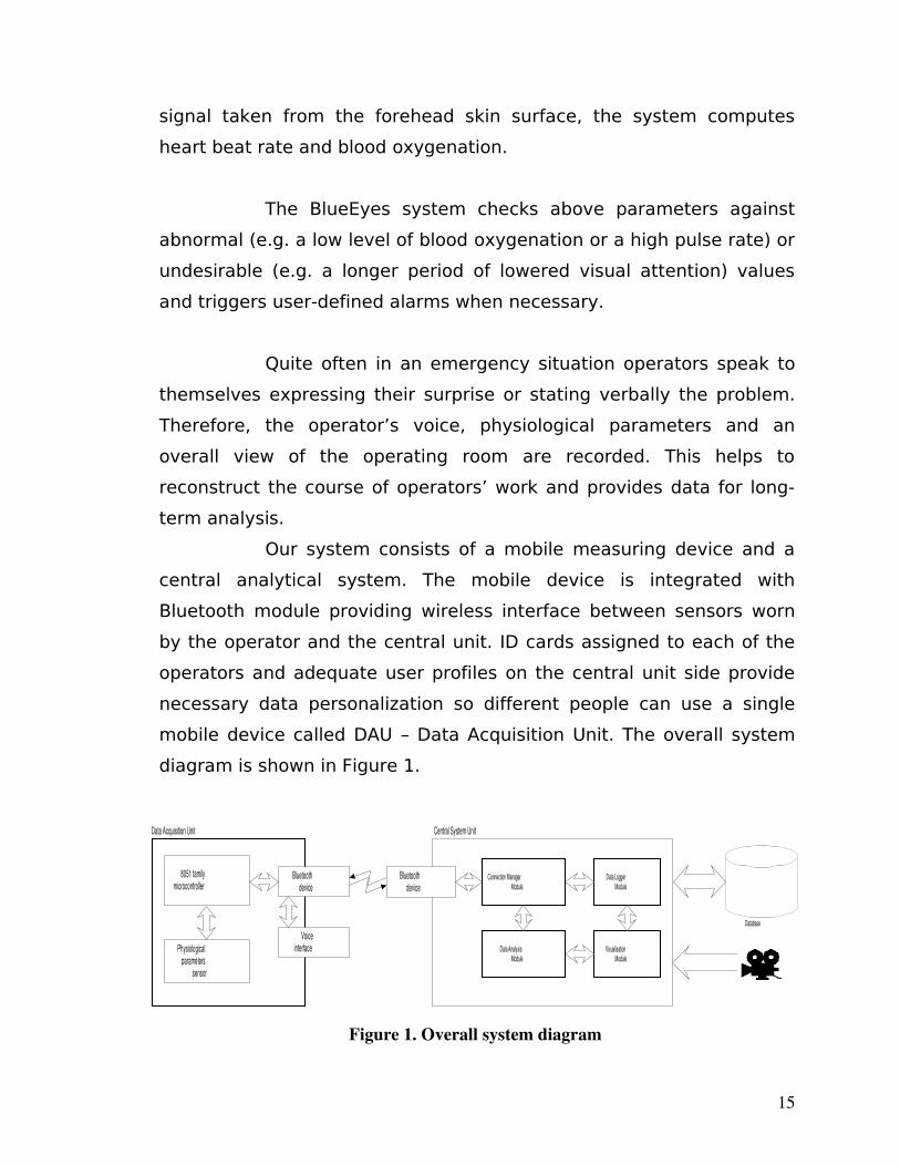
Our system consists of a mobile measuring device and a
central analytical system. The mobile device is integrated with
Bluetooth module providing wireless interface between sensors worn
by the operator and the central unit. ID cards assigned to each of the
operators and adequate user profiles on the central unit side provide
necessary data personalization so different people can use a single
mobile device called DAU – Data Acquisition Unit. The overall system
diagram is shown in Figure 1.
15
8051 familymicrocontroller
Physiologicalparameters
sensor
Bluetoothdevice
Database
Bluetoothdevice
Connection ManagerModule
Data LoggerModule
Data AnalysisModule
VisualisationModule
Data Acquisition Unit Central System Unit
Voiceinterface
Figure 1. Overall system diagram
The tasks of the mobile Data Acquisition Unit are to
maintain Bluetooth connections, to get information from the sensor
and sending it over the wireless connection, to deliver the alarm
messages sent from the Central System Unit to the operator and
handle personalized ID cards. Central System Unit maintains the other
side of the Bluetooth connection, buffers incoming sensor data,
performs on-line data analysis, records the conclusions for further
exploration and provides visualization interface.
Performance requirements
The portable nature of the mobile unit results in a number
of performance requirements. As the device is intended to run on
batteries, low power consumption is the most important constraint.
Moreover, it is necessary to assure proper timing while receiving and
transmitting sensor signals. To make the operation comfortable the
device should be lightweight and electrically safe. Finally, the use of
standard and inexpensive ICs will keep the price of the device at
relatively low level.
The priority of the central unit is to provide real-time buffering of
incoming sensor signals and semi-real-time processing of the data,
which requires speed-optimized filtering and reasoning algorithms.
Moreover, the design should assure the possibility of distributing the
processing among 2 or more central unit nodes (e.g. to offload the
database system related tasks to a dedicated server).
2.3 DATA ACQUISITION UNIT (DAU)
2.3.1Hardware
16
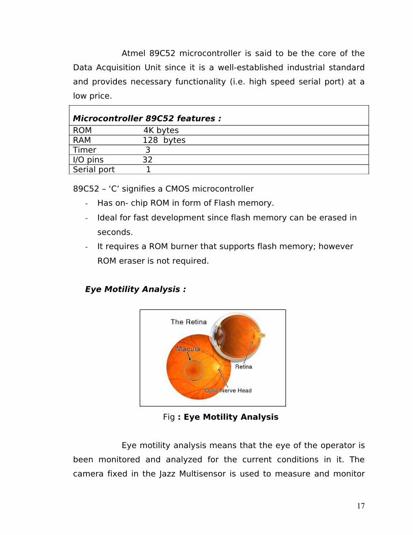
Atmel 89C52 microcontroller is said to be the core of the
Data Acquisition Unit since it is a well-established industrial standard
and provides necessary functionality (i.e. high speed serial port) at a
low price.
Microcontroller 89C52 features :
ROM 4K bytes RAM 128 bytesTimer 3 I/O pins 32 Serial port 1
89C52 – ‘C’ signifies a CMOS microcontroller
Has on- chip ROM in form of Flash memory.
Ideal for fast development since flash memory can be erased in
seconds.
It requires a ROM burner that supports flash memory; however
ROM eraser is not required.
Eye Motility Analysis :
Fig : Eye Motility Analysis
Eye motility analysis means that the eye of the operator is
been monitored and analyzed for the current conditions in it. The
camera fixed in the Jazz Multisensor is used to measure and monitor
17
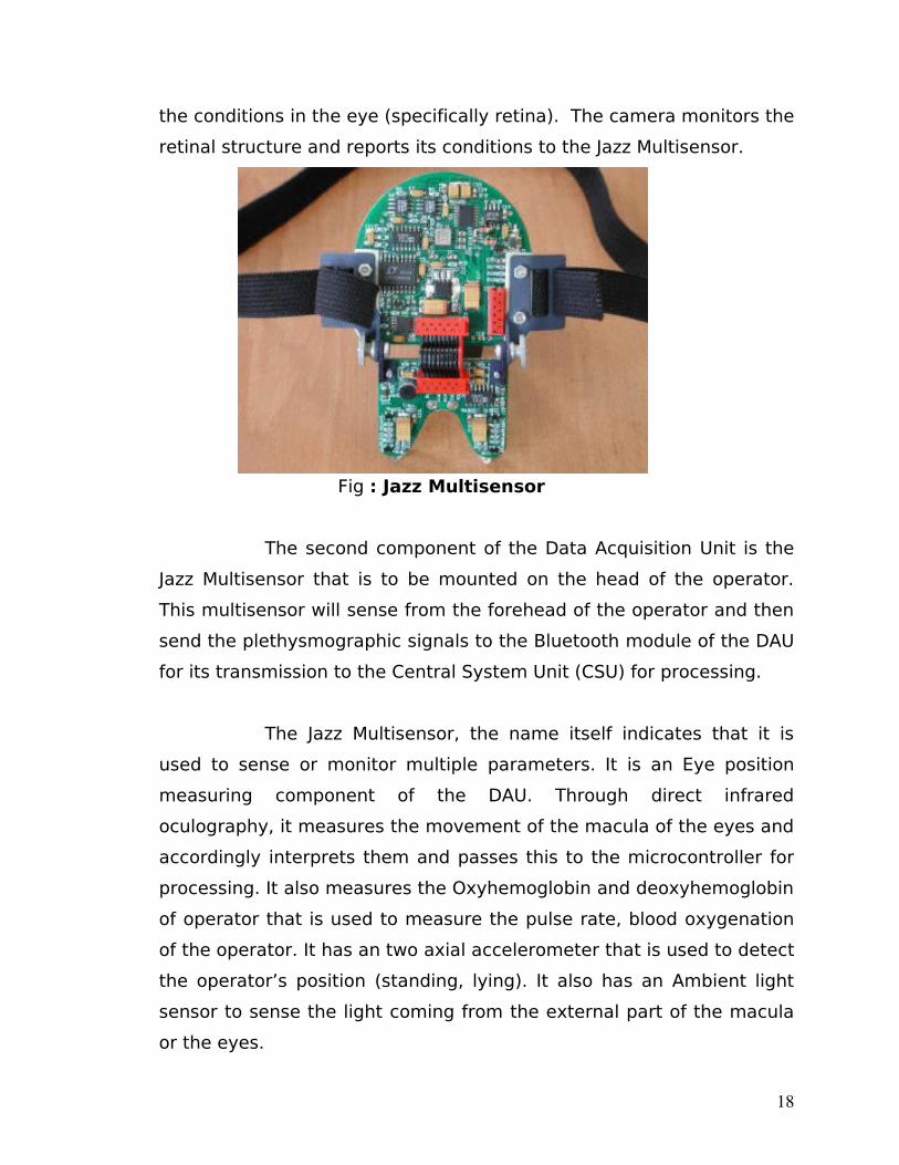
the conditions in the eye (specifically retina). The camera monitors the
retinal structure and reports its conditions to the Jazz Multisensor.
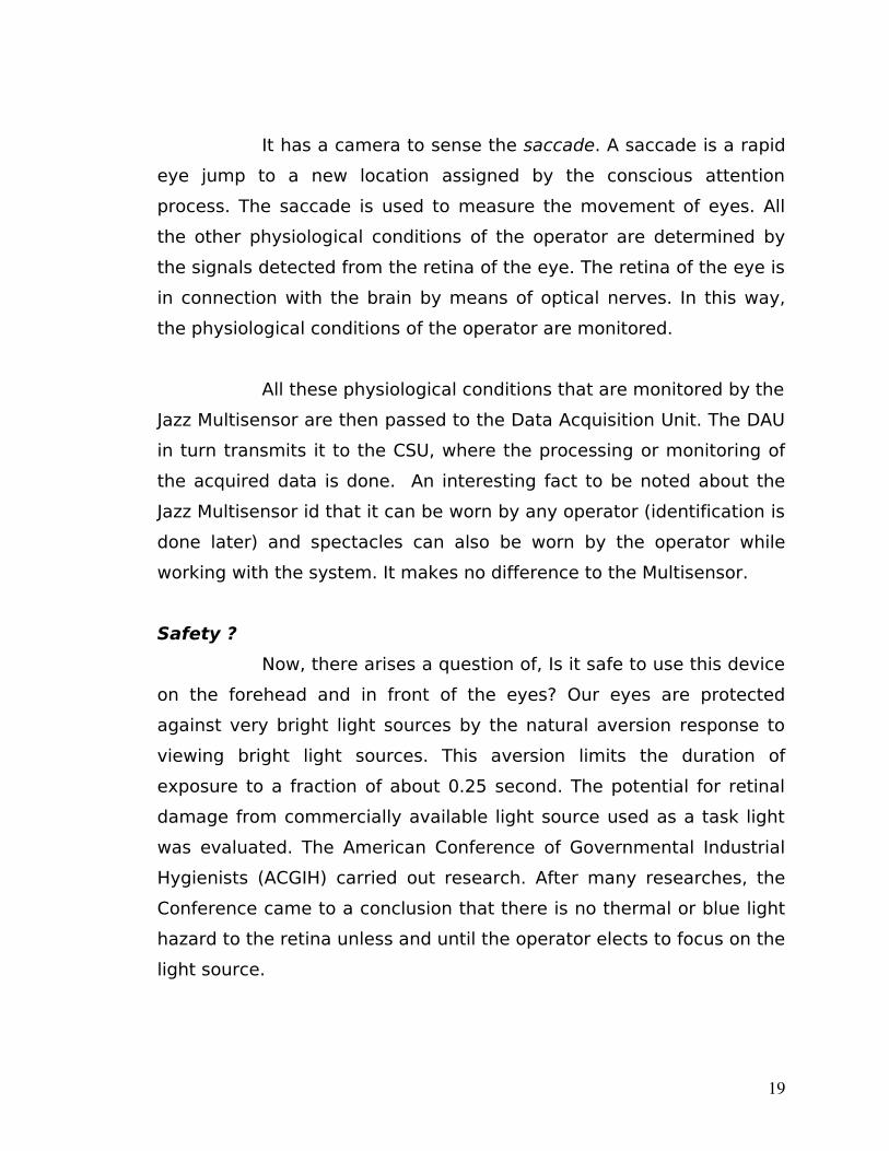
Fig : Jazz Multisensor
The second component of the Data Acquisition Unit is the
Jazz Multisensor that is to be mounted on the head of the operator.
This multisensor will sense from the forehead of the operator and then
send the plethysmographic signals to the Bluetooth module of the DAU
for its transmission to the Central System Unit (CSU) for processing.
The Jazz Multisensor, the name itself indicates that it is
used to sense or monitor multiple parameters. It is an Eye position
measuring component of the DAU. Through direct infrared
oculography, it measures the movement of the macula of the eyes and
accordingly interprets them and passes this to the microcontroller for
processing. It also measures the Oxyhemoglobin and deoxyhemoglobin
of operator that is used to measure the pulse rate, blood oxygenation
of the operator. It has an two axial accelerometer that is used to detect
the operator’s position (standing, lying). It also has an Ambient light
sensor to sense the light coming from the external part of the macula
or the eyes.
18
It has a camera to sense the saccade. A saccade is a rapid
eye jump to a new location assigned by the conscious attention
process. The saccade is used to measure the movement of eyes. All
the other physiological conditions of the operator are determined by
the signals detected from the retina of the eye. The retina of the eye is
in connection with the brain by means of optical nerves. In this way,
the physiological conditions of the operator are monitored.
All these physiological conditions that are monitored by the
Jazz Multisensor are then passed to the Data Acquisition Unit. The DAU
in turn transmits it to the CSU, where the processing or monitoring of
the acquired data is done. An interesting fact to be noted about the
Jazz Multisensor id that it can be worn by any operator (identification is
done later) and spectacles can also be worn by the operator while
working with the system. It makes no difference to the Multisensor.
Safety ?
Now, there arises a question of, Is it safe to use this device
on the forehead and in front of the eyes? Our eyes are protected
against very bright light sources by the natural aversion response to
viewing bright light sources. This aversion limits the duration of
exposure to a fraction of about 0.25 second. The potential for retinal
damage from commercially available light source used as a task light
was evaluated. The American Conference of Governmental Industrial
Hygienists (ACGIH) carried out research. After many researches, the
Conference came to a conclusion that there is no thermal or blue light
hazard to the retina unless and until the operator elects to focus on the
light source.
19
2.3.2Features of DAU
If the features of the Data Acquisition Unit (DAU) are to be
listed out, then they would be as follows:
• The unit is very light in weight. Since it comprises only of the Jazz
Multisensor, the Atmel microcontroller 89C52 and the Bluetooth
module that transmits or transfers the data or signals to and
from the Central System Unit (CSU).The Data Acquisition Unit
(DSU) is just the hardware device that is to be worn by the
operator on his forehead and the Jazz Multisensor, Atmel
microcontroller and Bluetooth module are embedded in the unit
itself. So the overall weight of the unit is very less as only the
unit needs to be housed on the operators forehead.
• The power that is required by the Data Acquisition Unit for its
operation is supplied by the batteries that are mounted on the
headset that is to be worn by the operator. The power is require
only for the operation of the microcontroller and the Bluetooth
module. This signifies that this unit in the system consumes
much less amount of power for its operation.
• The unit has a very simple functionality and also it is easy to use
by a common operator. It is simply to be worn by the operator,
not to look after it. It also does not disturb the operator in his
work, neither physically or morally.
• This unit takes care in regard to authentication also. It only
allows access to the legitimate users or rather operators of the
system. This is accomplished by making the use of personalized
20
ID cards that are to be inserted in the ID card interface. From
here they are tested for authorization. The personalized data of
the operator is also been embedded into the ID card that allows
the system unit to monitor the unique operator.
2.4 CENTRAL SYSTEM UNIT (CSU)
2.4.1Introductory Modules
CSU software is located on the delivered Toshiba
laptop, in case of larger resource demands the processing can be
distributed among a number of nodes. In this section we describe the
four main CSU modules (see Fig. 1): The various modules that are
included in this unit are:
• Connection Manager
• Data Analysis Module
• Data Logger Module
• Visualization Module.
The modules exchange data using specially designed single-producer-
multi-consumer buffered thread-safe queues. Any number of consumer
modules can register to receive the data supplied by a producer. Every
single consumer can register at any number of producers, receiving
therefore different types of data. Naturally, every consumer may be a
producer for other consumers.
2.4.2Connection Manager Module
Connection Manager’s main task is to perform low-level
Bluetooth communication using Host Controller Interface commands. It
is designed to cooperate with all available Bluetooth devices in order to
support roaming Additionally, Connection Manager authorizes
21
operators, manages their sessions, demultiplexes and buffers raw
physiological data.
Transport Layer Manager hides the details regarding actual
Bluetooth physical transport interface (which can be either RS232 or
UART or USB standard) and provides uniform HCI command interface.
Bluetooth Connection Manager is responsible for
establishing and maintaining connections using all available Bluetooth
devices. It periodically inquires new devices in an operating range and
checks whether they are registered in the system database. Only with
those devices the Connection Manager will communicate.
The data of each supervised operator is buffered
separately in the dedicated Operator Manager.
Operator Data Manager provides an interface to the
operator database enabling the other modules to read or write
personal data and system access information.
2.4.3Data Analysis Module
The module performs the analysis of the raw sensor data in
order to obtain information about the operator’s physiological
condition. The separately running Data Analysis Module supervises
each of the working operators. The module consists of a number of
smaller analyzers extracting different types of information. Each of the
analyzers registers at the appropriate Operator Manager or another
analyzer as a data consumer and, acting as a producer, provides the
results of the analysis. An analyzer can be either a simple signal filter
(e.g. Finite Input Response (FIR) filter) or a generic data extractor (e.g.
signal variance, saccade detector) or a custom detector module. The
computed features can be e.g. the operator’s position (standing,
walking and lying) or whether his eyes are closed or opened.
22
2.4.4Data Logger Module
The module provides support for storing the monitored
data in order to enable the supervisor to reconstruct and analyze the
course of the operator’s duty. The module registers as a consumer of
the data to be stored in the database. Each working operator’s data is
recorded by a separate instance of the Data Logger. Apart from the
raw or processed physiological data, alerts and operator’s voice are
stored. The raw data is supplied by the related Operator Manager
module, whereas the Data Analysis module delivers the processed
data. The voice data is delivered by a Voice Data Acquisition module.
2.4.5 Visualization Module
The module provides user interface for the supervisors. It
enables them to watch each of the working operator’s physiological
condition along with a preview of selected video source and his related
sound stream. Watching all the recorded physiological parameters,
alarms, video and audio data the supervisor is able to reconstruct the
course of the selected operator’s duty.
Features
Some of the features of the Central System Unit are:
• The Bluetooth connection management of the two units.
• Data processing that has been acquired from the mobile device
or the Data Acquisition Unit.
• Visualization of the overall data acquired into an appropriate
format.
• The recording of the data into an external database using OBDC.
• Access verification of an operator, by matching his data with that
in system’s database.
23
• The overall maintenance of the system, as to the maintenance of
both the units.
CHAPTER 3 : SECURITY AND APPLICATION AREAS
3.1 SECURITY OF DATA IN THE SYSTEM
There are various levels of security perseverance in the
system. They can be enlisted as follows:
• Only registered mobile devices can connect to the system by
the means of unique ID cards maintained by each individual
operator. When the ID card is inserted in its interface then
there is an authorization process run, and piped to the process
is only the access allowed to the legitimate operators of the
system.
• Whenever a Bluetooth connection is to be established then also
there is an authentication procedure followed by the system to
allow access to only those operators those have a unique
identification and its representation or valid entry in the
database.
• Bluetooth connection encryption is maintained in the system
for authentication purposes.
• Access rights restrictions are also been imposed, so as to
maintain hierarchical structure in networks and to allow limited
access to the operator.
• Personal and physiological data encryption is another facet.
Only the operator and the system know what is its status, no
other intruder cannot have access to personal information.
24
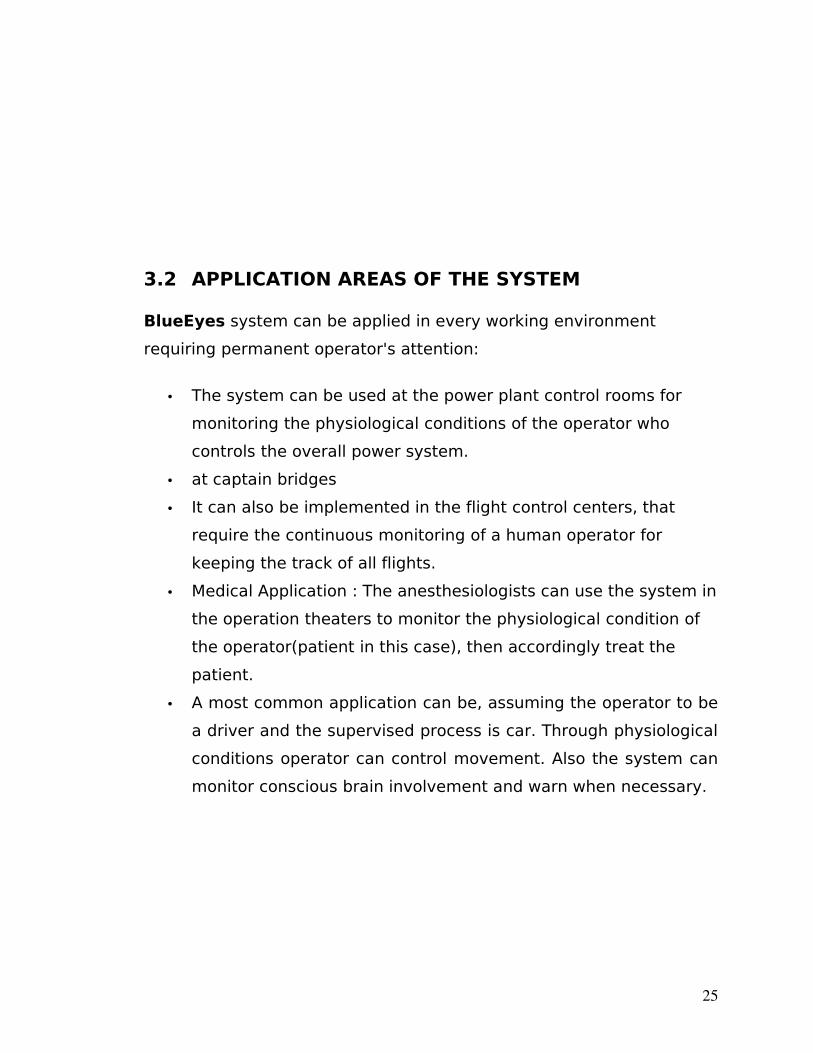
3.2 APPLICATION AREAS OF THE SYSTEM
BlueEyes system can be applied in every working environment
requiring permanent operator's attention:
• The system can be used at the power plant control rooms for
monitoring the physiological conditions of the operator who
controls the overall power system.
• at captain bridges
• It can also be implemented in the flight control centers, that
require the continuous monitoring of a human operator for
keeping the track of all flights.
• Medical Application : The anesthesiologists can use the system in
the operation theaters to monitor the physiological condition of
the operator(patient in this case), then accordingly treat the
patient.
• A most common application can be, assuming the operator to be
a driver and the supervised process is car. Through physiological
conditions operator can control movement. Also the system can
monitor conscious brain involvement and warn when necessary.
25

26
CHAPTER 4 : MERITS AND DEMERITS
In section gives a brief overview of the merits, demerits
and implementation trade-offs of the system.
4.1 MERITS OF THE SYSTEM
The system is able to
4.2 DEMERITS OF THE SYSTEM
The prototype built has several limitations, which are not
the result of the project deficiency but are rather caused by the
constraints imposed by the Project Kit and small budget. In the
commercial release the USB web-cam should be replaced by an
industrial camera, connected to a capturing device. The use of such a
camera would lessen CPU load and improve the video signal quality.
Since the Bluetooth module does not support redirecting of
the voice SCO connections data to the serial port (which is a part of the
Bluetooth specification) PCM interface is built on the central system
side similar to the one used in the DAU. This makes the Voice Data
Acquisition module receive the sound using the sound card.
27
CHAPTER 5 : A GENERIC TOUCH TO THE FUTURE OF THE SYSTEM
5.1 FUTURE ENHANCEMENTS IN THIS SYSTEM
There lies an immense scope in the improvement of this system.
Rather the commercial implementation of this system holds much
ground in this dynamic era of computer sciences.
• The use of a miniature CMOS camera integrated into the eye
movement sensor will enable the system to calculate the point of
gaze and observe what the operator is actually looking at.
• Introducing voice recognition algorithm will facilitate the
communication between the operator and the central system
and simplify the authorization process.
Despite considering in the report only the operators working in control
rooms, the solution may well be applied to everyday life situations.
• Assuming the operator is a driver and the supervised process is
car driving it is possible to build a simpler embedded on-line
system, which will only monitor conscious brain involvement and
warn when necessary. As in this case the logging module is
redundant, and the Bluetooth technology is becoming more and
more popular, the commercial implementation of such a system
would be relatively inexpensive.
• The system can also be implemented to its optimal level in
various other scenarios like that of in the power plant control
stations to monitor the physiological condition of the operator. As
this system implements a very vivid technology called the
Bluetooth technology, the use of this technology facilitates the
minimization of the cost of implementation of the system and
28
also this system can be utilized by many common end users.
Only the norms and the system architectural design have to be
known to only the systems’ administrator.
• The system can also make use of the Data mining algorithms.
Data mining is the extraction of information from databases. The
use of this technique will increase the efficiency of the retrieval
of information from databases as and when needed and also, for
keeping the track of identification of various operators of system
in the database.
29
CHAPTER 6 : SUMMARY
Starting with the name of the system, BlueEyes
emphasizes– Bluetooth technology and the movements of the eyes.
Bluetooth provides reliable wireless communication whereas the eye
movements enable us to obtain a lot of interesting and important
information using the eye motility analysis.
The BlueEyes system is developed because of the need for
a real-time monitoring system for a human operator. The approach is
innovative since it helps supervise the operator not the process, as it is
in presently available solutions. The system in its commercial release
will help avoid potential threats resulting from human errors, such as
weariness, oversight, tiredness or temporal indisposition. However, the
prototype developed is a good estimation of the possibilities of the
final product.
No doubt, there are some lacunas in the system, but these
are present only because the system is developed on the project basis.
This is done only to limit the cost of the system. The commercial
implementation of the system can resolve the lacunas.
In recent years, Bluetooth technology is becoming more
and more popular; the commercial implementation of such a system
30
would be relatively inexpensive. And if a large scale implementation is
done, then such a system will definitely prove to be a boon for the
human race in course of time.
BIBLIOGRAPHY
Books:
• 8051 Microcontroller and Embedded Systems
(for Basics of 8051 family microcontrollers and Serial
Communication Principles)
Author : Mazidi and Mazidi
• Wireless Technology Manual 4.5
(for Basics of Bluetooth Technology)
Websites :
• www.google.com
• www.bluetooth.com
• www.poznan.net
• www.bluemax.com/eyessafe
• www.wikipedia.org
31