Embed Size (px)
Citation preview

1
GOVERNMENT OF TAMILNADU
DIRECTORATE OF TECHNICAL EDUCATION CHENNAI – 600 025
STATE PROJECT COORDINATION UNIT
Diploma in Electronics And Communication
Engineering
Course Code: 1040
M – Scheme
e-TEXTBOOK
on
TELEVISION ENGINEERING for
VI Semester DECE Convener for ECE Discipline: DR.M.JEGANMOHAN,M.E.,MBA.,Ph.D.,(Management).,Ph.D.,(Engg).,M.I.S.T.E.,
Principal, Govt. Polytechnic College,
Uthappanaickanoor, Usilampatti, Madurai – 625 536
Team Members for Television Engineering
1. Mrs.R.Mini,M.E., HOD/ECE,
Latha Mathavan Polytechnic College, Kidaripatti,Madurai-625301
2. Mrs.R.Menaka,M.E., Senior Lecturer/ECE,
Latha Mathavan Polytechnic College, Kidaripatti,Madurai-625301
3. Mrs.R.Rajameenal,B.E., Lecturer/ECE,
Latha Mathavan Polytechnic College, Kidaripatti,Madurai-625301
Validated by
Dr. Mohamed Mansoor Roomi,M.E.,Ph.D
Asst Professor(sel grade)/ECE department,
Thiagarajar college of Engineering,
Madurai – 625 015

2
GOVERNMENT OF TAMILNADU
DIRECTORATE OF TECHNICAL EDUCATION CHENNAI – 600 025
STATE PROJECT COORDINATION UNIT
Diploma in Electronics And Communication
Engineering
Course Code: 1040
M – Scheme
e-TEXTBOOK
on
TELEVISION ENGINEERING for
VI Semester DECE Convener for ECE Discipline: DR.M.JEGANMOHAN,M.E.,MBA.,Ph.D.,(Management).,Ph.D.,(Engg).,M.I.S.T.E.,
Principal, Govt. Polytechnic College,
Uthappanaickanoor, Usilampatti, Madurai – 625 536
Team Members for Television Engineering
1. Mrs.R.Mini,M.E., HOD/ECE,
Latha Mathavan Polytechnic College, Kidaripatti,Madurai-625301
2. Mrs.R.Menaka,M.E., Senior Lecturer/ECE,
Latha Mathavan Polytechnic College, Kidaripatti,Madurai-625301
3. Mrs.R.Rajameenal,B.E., Lecturer/ECE,
Latha Mathavan Polytechnic College, Kidaripatti,Madurai-625301
Validated by
Dr. Mohamed Mansoor Roomi,M.E.,Ph.D
Asst Professor(sel grade)/ECE department,
Thiagarajar college of Engineering,
Madurai – 625 015

3
34081 – TELEVISION ENGINEERING
UNIT 1-TELEVISION FUNDAMENTALS
Monochrome TV: Basic block diagram of Monochrome TV transmitter and Receiver – Scanning process –
horizontal, vertical and sequential scanning – flicker – interlaced scanning (qualitative treatment only) – need
for synchronization – blanking pulses – Aspect ratio– Resolution – Types – vertical and horizontal resolution –
video bandwidth – composite video signal (CVS)– CVS for one horizontal line – Definitions for Vertical sync
pulse, Serrated vertical pulse, Equalizing pulse – Positive & Negative modulation - TV Standards – List of
Types of TV standards. Color T.V. Fundamentals: Additive mixing of colors –Types – color perception –
Chromaticity diagram – Definition for Luminance, Hue Saturation and Chrominance Formation of
chrominance signal in PAL system with weighting factors.
UNIT 2-CAMERA AND PICTURE TUBES
CAMERA TUBE: Characteristics – Types of camera tube – working principle of Vidicon and Plumbicon
camera tube, CCD camera – Video processing of camera pick up signal – Block diagram and Principle of
working of color TV camera tube.
PICTURE TUBE : Construction and working of Monochrome picture tube – screen phosphor – screen burn –
Screen Persistence - Aluminized screen – Types of color picture tubes -construction and working principle of
Delta gun and Trinitron Color picture tubes – Automatic degaussing.
UNIT 3-TELEVISION TRANSMITTER
Types –Comparison - Principle – Block diagram of Low level IF Modulated TV transmitter –Visual Exciter –
Aural Exciter – principle of working of CIN Diplexer –Block diagram of color TV transmitter – color
compatibility – PAL color coder –functional blocks and working of each block – Merits and demerits of PAL
system.
UNIT 4- TELEVISION RECEIVER
Block diagram of Monochrome Receiver – functions of each block – Need for AGC – Advantages of AGC –
Video amplifier requirements –High frequency & Low frequency compensation – Block diagram of PAL color
Receiver – Need for sync separator – Basic sync separator circuits– Vertical sync separation & Horizontal sync
separation – AFC – Need for AFC – Horizontal AFC – Hunting in AFC – Anti Hunt network.
UNIT 5-ADVANCED TELEVISION SYSTEMS
Block diagram of a digital color TV receiver – Remote control IR transmitter and receiver – Closed Circuit TV
system–Applications of CCTV – scrambler – necessity - basic principle- types Descrambler block diagram -
Telecine equipment – Digital CCD Telecine system -Introduction to High definition TV (HDTV) and 3DTV.
Blue Ray Disc(BD)- The DVD player – Block diagram- Desirable Features & outputs of DVD players-DVD
player Models - USB flash drive(pen drive).

4
SYLLABUS
UNIT – I
TELEVISION FUNDAMENTALS 5-26
UNIT – II
CAMERA AND PICTURE TUBES 27-42
UNIT – III
TELEVISION TRANSMITTER 44-53
UNIT – IV
TELEVISION RECEIVER 54-72
UNIT – V
ADVANCED TELEPHONE SYSTEMS 73-88
CONTENTS

5
UNIT – I TELEVISION ENGINEERING
1.1 TV FUNDAMENTALS
INTRODUCTION:
Television means Tele + Vision, i.e., Television is used to see the picture telecast from long distance.
In TV transmission both picture and sound are transmitted. For picture AM Modulation is used and for sound
FM modulation is used.
1.1.1 BASIC BLOCK DIAGRAM OF TV TRANSMISSION:
The simplified block diagram of a Monochrome TV Transmitter is shown.
It consists of Television Camera, Video amplifier, AM Modulating amplifier, Audio amplifier, FM
Modulating amplifier, FM sound transmitter, Crystal oscillator, RF amplifier, Power amplifier, Scanning and
Synchronizing Circuits, Combining network, Transmitting antenna and Microphone.

6
• TELEVISION CAMERA:
Its function is to convert optical image of television scene into electrical signal by the
scanning process.
• VIDEO AMPLIFIER:
Video amplifier amplifies the video signal.
• AM MODULATING AMPLIFIER
The video signals are amplified by the modulating amplifier to get the modulated signal.
• AUDIO AMPLIFIER
Audio amplifier amplifies the electrical form of audio signal from the microphone.
• FM MODULATING AMPLIFIER:
Sound signal from audio amplifier is frequency modulated by FM Modulating amplifier.
• FM SOUND TRANSMITTER:
FM modulated amplified signal is transmitted through this FM sound transmitter to
transmitting antenna through the combining network.
• CRYSTAL OSCILLATOR:
Crystal Oscillator generates the allotted picture carrier frequency.
• RF AMPLIFIER:
RF amplifier amplifies the picture carrier frequency generated by crystal oscillator to
required level.
• POWER AMPLIFIER:
Power amplifier varies according to the modulating signal from AM modulating amplifier.
1.1.2 SCANNING AND SYNCHRONIZING CIRCUITS
Scanning is the process where picture elements are converted into corresponding varying
electrical signal
COMBINING NETWORK
Combining network is used to isolate the AM picture and FM sound signal during
transmission.

7
TRANSMITTING ANTENNA:
Transmitting antenna receives the AM picture signal and FM sound signal from combining
network for radiation as electromagnetic waves.
MICROPHONE:
Converts sound associated with picture being televised into proportionate electrical signal.
1.1. 3 SIMPLE BLOCK DIAGRAM OF TV
RECEPTION BASIC MONOCHROME TV
RECEIVER
Block diagram of a monochrome TV receiver is shown. It consists of RF Tuner, Receiver
antenna, common IF amplifier, video detector, video amplifier, scanning and synchronizing circuits,
sound IF amplifier, FM Sound demodulator, Audio amplifier, Loud Speaker, Picture tube.
RF TUNER:
RF Tuner selects the desired channel frequency band from the receiving antenna.
RECEIVER ANTENNA:
Receiver antenna intercepts the radiated RF signals and sends it to RF Tuner.
COMMON IF AMPLIFIER:
There are 2 or 3 stages of IF amplifiers.
VIDEO DETECTOR:
Used to detect video signals coming from last stage of IF amplifiers.

8
VIDEO AMPLIFIER:
It amplifies the detected video signal to the level required.
SCANNING AND SYNCHRONIZING CIRCUITS:
Scanning is the process where picture elements are converted into corresponding varying
electrical signals.
SOUND IF AMPLIFIER:
Detected audio signal is separated and selected for its IF range and amplified.
FM SOUND DEMODULATOR:
FM Sound signal is demodulated in this stage.
AUDIO AMPLIFIER:
FM demodulated audio signal is amplified to the required level to feed into the loud speaker.
LOUD SPEAKER:
Loud Speaker converts FM demodulated amplifier signal associated with picture being
televised into proportionate sound signal.
PICTURE TUBE:
In picture tube the amplified video signal is converted back into picture elements.
SCANNING:
Scanning is the process used to convert the optical into electrical signal. Fastest movement of
electron beam on the image is called scanning.
1.2 SCANNING PROCESS:
Scanning process is a technique similar to reading of written information on a page starting at
the top left and processing line by line downwards to the end at the bottom right.
Scanning is done frame by frame. Each frame consists of 625 horizontal lines. Each frame is
scanned at a rate of 25 frames / sec.

9
Scanning types,
1.Horizontal Scanning
2.Vertical Scanning
3.Sequential (or) Progressive Scanning
4.Interlaced Scanning.
1.3 HORIZONTAL SCANNING (H-SCANNING)
Movement of electron beam from left to right on the screen is known as trace period. When
the beam returns quickly from right to left is called retrace or fly back.
Trace and retrace period together in horizontal direction is known as HorizontalScanning.
Horizontal frequency = Number of lines in a Frame * Number of frames/sec
= 625 * 25 = 15,625 Hz
1.4 VERTICAL SCANNING (V – SCANNING)
Movement of electron beam in vertical direction. Movement of electron beam from top to
bottom is called trace. Movement of beam from bottom to top of the frame is called retrace.

10
Vertical frequency = Number of frames /sec= 25 Hz
1.5 SEQUENTIAL (OR) PROGRESSIVE SCANNING:
Sequential or progressive Scanning is the process in which both horizontal and vertical
directions are scanned simultaneously to provide complete pictures. Horizontal lines are scanned one
by one. So complete picture will be scanned through this type.
1.6 FLICKER:
The sensation produced by incident light on the nerves of the eyes retina does not cease
immediately. It persists for about 1/25th
of a second (.062 Sec.) This storage characteristic is called
as persistence of vision of eye.
Flicker means if the scanning rate of picture is low, the time taken to move one frame to
another frame will be high. This results in alternate bright and dark picture in the screen. This is
called “Flicker”.
To avoid flicker, the scanning rate of the picture should be increased i.e. 50 frames/Sec.
1.7 INTERLACED SCANNING:
To reduce flicker, the vertical scanning is done 50 times per second in TV system. However
only 25 frames are scanned per sec.
In interlaced scanning the 625 lines are grouped into two fields. They are called as even field
and odd field. Each field contains 312.5 lines. Even field contains even numbered lines and odd field
contains odd numbered lines.
During first scanning line numbers 1, 3, 5 are scanned. During next scan, line numbers 2, 4,
6.... are scanned. That is alternate lines are scanned every time. So to cover each frame, scanning is

11
done two times.Here the vertical rate of scanning is increased twice. So it will reduce flicker.
Interlaced scanning is shown. Now the vertical frequency is 50 Hz. But there is no change in
horizontal frequency.
Horizontal frequency = Number of lines in a Frame * Number of frames/sec
= 312.5 * 50 = 15,625 Hz
1.7.1 SCANNING PERIODS:
Useful video signals are obtained during the trace period only. So the trace time is larger than
the retrace time.
HORIZONTAL:
Tracing = 52 µs
Retracing = 12 µs
Total time period = 64 µs.
VERTICAL:
Tracing = 18.722ms
Retracing = 1.27ms
Total time period = 20ms.
Horizontal frequency = 15,625 H2
Horizontal time = 1/T = 1/15,625 = 64s.
Vertical Frequency = 50 Hz Vertical Time
= 1/50 = 20 ms
Number of Horizontal lines lost during Vertical retrace = Vertical retrace time
One horizontal time
= 1.28 ms = 20 lines
64s
So 20 lines are lost per field and in total 40 horizontal lines are lost during the scanning of each Frame.

12
Active number of lines (Na) = 625 – 40 = 585 lines.
Detailed structure of interlaced scanning is shown. This is also called as 2: 1 interlaced scanning.
1.8 NEED FOR SYNCHRONIZATION:
At any time the same co-ordinate will be scanned by the electron beam in both the camera
tube and picture tube. Otherwise distorted picture will be seen on the screen. So synchronization
between the transmitter and receiver is needed. For that we are using Sync pulses.
At the receiver side these pulses are identified, separated and used for triggering the
oscillator
circuit.
Horizontal Sync pulse time period = 4.7 µSec.
Horizontal Sync pulse Frequency =15,625 Hz.
Vertical Sync pulse time period = 160 µSec.
Vertical Sync pulse frequency = 50 Hz.
1.9 BLANKING PULSES :
The video signal obtained during the horizontal and vertical retrace are not useful one. So
there is no need to transmit them.

13
So to make the retrace signal invisible we are using blanking pulses.During horizontal blanking,
horizontal retrace is blanked. This is 19% of horizontal time period.
Horizontal blanking = 64 * .19 = 12 µSec.
Remaining 52 v Sec contains picture information and this is called as active line period. For a single
line one blanking pulse is needed. So for 1 sec, 15,625 blanking pulses are needed.
In vertical retrace, for one frame two vertical blanking pulse is needed. So in 1 sec, 25 frames
are scanned and so 50 V blanking pulses are needed.
Vertical blanking = 20 H
= 20 x 64 µ Sec. = 1280µ Sec.
1.10 ASPECT RATIO:
The ratio between width to height of rectangle picture frame adopted in TV system is known
as aspect ratio.
Aspect ratio = Width = 4 or 4: 3
Height 3
Reasons for having this ratio is,
1. Most of the objects are moving only in horizontal plane.
2. Our eye can see the movement of object comfortably only in horizontal plane than in vertical
plane.
3. The frame size of motion picture already existing is having the aspect ratio of 4 : 3
1.11 HORIZONTAL AND VERTICAL RESOLUTION
The ability of the image reproducing system to resolve the fine details of the picture
distinctly in both horizontal and vertical direction is called as “resolution”.

14
• VERTICAL RESOLUTION:
The ability to resolve and reproduce fine details of picture in vertical direction iscalled as Vertical
resolution.
Vertical resolution (VR) = No. of active lines * Kell factor or resolution factor
= Na * k= 585.69 = 400Lines
• HORIZONTAL RESOLUTION :
The ability of the system to resolve maximum number of picture elements along the scanning
determines the horizontal resolution.
Horizontal resolution = VR * Aspect ratio
= 400 * 4/3= 534 Pixels
1.12 VIDEO BANDWIDTH :
Video Bandwidth = One horizontal line
signal
One horizontal line tracing
= 267
52 *10-6
= 5 MHz
Video Bandwidth = Horizontal Resolution = 534 = 5 MHz
2* One Horizontal line scan 2*52 *10-6
1.13 POSITIVE AND NEGATIVE TRANSMISSION:
• POSITIVE TRANSMISSION (POSITIVE MODULATION)
In this type of transmission, if the brightness of picture increases, then video signal
amplitude also increases. So peak white corresponds to 100% modulation level. And sync level
corresponds to minimum level.

15
• NEGATIVE TRANSMISSION (NEGATIVE MODULATION)
In negative transmission, if the brightness of the picture increases, then video signal
amplitude decreases. So the peak white corresponds to near zero level.
1.13.1 ADVANTAGES OF NEGATIVE TRANSMISSION:
1.Due to noise pulses, the video signal amplitude increases and produce black dots on the screen.
This will create much low disturbance compared to white dots produced in positive modulation.
2.Since most of the video signal are white, the video signal is low and transmitted power is less.
3.The sync pulse level at 100% are used at the receiver as AGC reference levels.
1.13.2 COMPARISON OF POSITIVE AND NEGATIVE TRANSMISSION
POSITIVE MODULATION NEGATIVE MODULATION PARTICULARS
White dots Black dots Noise
High Low Transmitting – power
Low High Efficiency
100% 10 % White level
25% 75 % Black level
28 % 78 % Blanking level
0 % 100 % Syno pulse level
1.14 COMPOSITE VIDEO SIGNAL (CVS)
CVS consists of,
• Camera signal corresponding to the picture to be transmitted.
• Blanking pulses to made the retrace invisible.
• Sync pulse to synchronize the transmitter and
receiver.

16
Details, Total amplitude is 100%
Y- axis Amplitude:
Extreme White level = 10%
Tolerance ± 2.5%
Black level = 70 % amplitude. Blanking retrace period amplitude increase to 70 %. But
actually, blanking pulse of amp 75 % used
Blanking Pulse = 75% amplitude
Sync Pulse = 75% to 100% amplitude
X- axis Time details
H – Sync pulse time = 4.7 v Sec.
Horizontal tracing time = 52 v Sec.
Horizontal retracing time = 12 v Sec.

17
Difference between black level and blanking level is called as Pedestal.
Average value of video signal is DC component. Distance between DC Component and
pedestal is called as pedestal height.
• FRONT PORCH:
Rising edge of sync pulse and blanking does not coincide. The time difference between the
raising edge of sync and blanking pulse is called as ‘Front Porch”. It is 1.5 vs, ± .34 is tolerance. If
front porch is not their sync. Pulse is build at varying fixed level and varying brightness level.
• BACK PORCH:
Difference between the failing edge of sync pulse and blanking pulse is called back porch.
1. It allows horizontal fly back.
2. Used as reference level to preserve DC component.
3. Used to send colour burst signal in colour Transmission.
4. Used as AGC reference level in receiver circuits.
1.15 VERTICAL SEPRATED SYNC PULSE:

18
Here, vertical sync pulse of duration 160 s is divided into 5 pulses of duration 32 that too
4.7 on and 27.3 OFF period. This process is called as “serration”. This 4.7 sON is separated to
have horizontal synchronization and it is given to differentiator the serrated pulses are given to
integrator to get it as a single sync pulse.
But here for odd and even fields their occurs time error due to trigger level in both
fields. Because of charging and discharging of capacitor in the integrator.
The time error due to trigger level of fields is called as “Half line discrepancy” occurs. To avoid
half line discrepancy we are adding the equalizing pulses.
Time error is because for second field in capacitor residual potential is zero. But for odd field,
charging occurs of first field i.e., 312.5 lines. So there is some residual voltage and half line
discrepancy occurs.
1.16 EQUALISING PULSES:
To avoid half line discrepancy due to time error in trigger level, equalizing pulses are used.
These pulses are having duration of 2.3 vsec ON period and 27.4 vsec OFF period. Due to
these pulses time error is completely avoided. The pulses added before the vertical sync pulse are
called as “pre-equalising pulse and that added after the vertical sync pulses are called as post
equalising pulses. Since the pulses are having a short duration 2.3 vsec the capacitor is charged to
only small value. So before the start of vertical sync, during both field the capacitor is discharged to
zero level.

19
Similarly due to post-equalising pulses this capacitor is discharged quickly. If the discharge
is slow than the trailing edge, of integrator may false trigger the oscillator. The structure of pre and
post equalising pulses are shown.
1.17 LIST OF TV STANDARDS
i) FCC (Federal Communication Commission
ii) NTSC (National Television system Committee)
iii) CCIR ( International Radio Consulative Committee)
iv) SECAM (Sequential Couleures A Memory)
1.18 COLOUR TV FUNDAMENTALS:
In system we are sending only the luminance information. But in colour system we have to
send information about the colours also. All colour TV system are based on the principle of our eye.
Here wavelength unit is Arm strong. Visible spectrum – 4000 A⁰ to 7000 A⁰.
1A⁰ = 10-10
m 1nm = 10A⁰
The three basic colors are called as primary colors. They are Red, Green and Blue. To get
different color shading we have to mix primary colors. We have two types of mixing
1. Additive Mixing
2. Subtractive Mixing.
1.19 ADDITIVE MIXING:
In this method two or three primary colours are mixed together to form a new color. By
mixing primary colours with different intensities we can obtain all types of colours.
Fig shows the method of additive mixing. By mixing 30% Red, 59% Green and 11% blue we
can get white color

20
Y = 0% + 59%9+11%B
Red + Blue = Magenta (41%).
Blue + Green = Cyan (70%)
Red + Green = yellow (89%)
1.20 COMPLEMENTARY COLOUR:
Color obtained by mixing only two primary colours is called as complementary colours.
Primary Complementary
Red + Green = Yellow
Red + Blue = Magenta
Blue + Green = Cyan
1.21 SUBTRACTIVE MIXING.
In Subtractive mixing, the reflecting properties of colour pigments are used. A colour
pigment can absorb all the colour wavelength except its characteristic colour wavelength. Its
characteristic colour frequency alone is reflected. If we are mixing two or three colour pigments, then
a color wavelength common to them only reflected. This method of mixing is generally used in
colour printing and colour painting. By mixing primary colours, black colour is got.
Different colours are obtained by subtracting primary and secondary colours from white. So this is
called as subtractive mixing.

21
1.22 COLOUR PERCEPTION:
The retina on the backside of our eye has light sensitive organs. They can be able to sense the
light variations. Also the retina is connected to optical centre of the brain optical nerves.
We have two types of light sensitive organs. They are called rods and cones. Rods are used to
identify brightness variations. Cones are used to identify color information. The colours are
transferred to optical nerves. They are then mixed together to identify the original colour.
1.23 CHROMATICITY DIAGRAM:
Chrominance or chromaticity diagram is a graphical representation of primary colours and all
other colours in a space co-ordinate. Based on principle of tristimulus value, white color is formed by
mixing 30% red, 59% green and 11% blue.
Below Fig is a two dimension graph representing hue and saturation on x-y plane. In 3D
representation 2 axis is used to identify the brightness of the color.
Chromaticity diagram is in shape of horse shoe. On the three corners we have primary colours and on
perimeter different colours are available. On moving towards centre pure colours are mixed with
white and desaturated. Point ‘C’ represents white color. This point is at co-ordinate of x = 31,
y = .32. Sunlight, sky light and day light are all different forms of white light.

22
1.23.1 ADVANTAGES:
Using this diagram we can identify the color obtained by additive mixing process. If bright
increases, Z axis also increase and chrominance diagram becomes enlarged in 3D representation.
1.24 LUMINANCE, HUE AND SATURATION:
All the colours are having the following three characteristics. 1. Hue, 2. Saturation, 3.Luminance.
• LUMINANCE:
It is the amount of light intensity as perceived by the eye regardless of the colour. It is also
called as brightness signal, y signal, and white signal.
• HUE (TINT)
It is the predominant spectral colour. For example, green leaf has a green hue and red apple has red
hue.
• SATURATION:
It will indicate the spectral purify of colour. i.e., it will indicate how much white mixed with
a particular colour.

23
• CHROMINANCE:
Hue and Saturation together are called as chrominance or chroma signal.
1.25 FORMATION OF CHROMINANCE SIGNAL IN PAL SYSTEM WITH WEIGHTING
FACTOR:
PAL system u or v signals.
U = .44 B - .29G .15 R
V = .61R - .52G - .1B
Es: Yellow colour,
y = R + G
U = -.29 +(-.15)
= -.44
V = .61 + (-.52)= .09
Yellow colour chrominace signal
C = √u2
+ v2
= √(-.44)2
+ (.09)2
C = ± .44
Yellow colour y signal value,
y = R +G
= .3 + .59 = .89

24
Table of PAL system.
S.No. Colour Basic Colour Y U V C
1. White R1G1B 1 0 0 0
2. Yellow R14 .89 -.44 .09 ±.44
3. Cyan G1B 0.7 .15 -.6 ±.63
4. Green G 0.59 -.29 -.52 ± .59
5. Magenta R. 4 .41 .29 .51 ±.59
6. Red R .3 -.15 .61 ±.63
7. Blue B .11 .44 .1 ±.44
8. Black - 0 0 0 0

25
REVIEW QUESTIONS
PART-A
1. Define television (TV) or what is TV?
2. Define scanning.
3. Define scanning process.
4. Mention the value for horizontal frequency.
5. Mention the value for vertical frequency.
6. Define flicker.
7. How many number of horizontal lines lost during vertical retrace?
8. How many active lines are there in interlaced scanning?
9. List the value for H-sync pulse period.
10. List the value for V-sync pulse period.
11. Mention the H-sync pulse frequency.
12. Mention the v-sync pulse frequency.
13. Mention the H-blanking period.
14. Mention the v-blanking period.
15. What is the vertical resolution factor?
16. Define interlaced scanning.
17. Define resolution.
18. Mention video bandwidth frequency.
19. Define front porch.
20. Define back porch.
21. What is vertical serrated sync pulses?
22. What is serration?
23. What is half line discrepancy error?
24. Define equalizing pulse.
25. List some TV standards.
26. What is additive mixing?
27. What is subtractive mixing?
28. What is color perception?
29. List out the advantage of chromaticity.
30. Define luminance.
31. Define Hue (tint).
32. Define saturation.

26
PART-B
1.Define video bandwidth.
2.Compare different TV standards.
3.What is horizontal scanning?
4.What is vertical scanning?
5.Explain sequential or progressive scanning.
6.Define blanking pulses.
7.Define aspect ratio.
8.Explain the reason for having this ratio as aspect ratio?
9.Define horizontal and vertical resolution.
10.Define positive and negative transmission.
11.Mention the advantage of negative transmission.
12.Compare positive and negative transmission.
13.Explain CVS?
PART – C
1. With neat block diagram explain the working of TV transmitter.
2. With neat block diagram explain the working of TV receiver.
3. Explain interlaced scanning in detail.
4. Explain the CVS for one horizontal line in detail.
5. With neat block diagram explain the working of vertical serrated sync pulses in detail.
6. With neat block diagram explain the working of equalizing pulses in detail.
7. Explain additive mixing.
8. Explain subtractive mixing.
9. Explain the chromaticity diagram in detail.

27
UNIT II
CAMERA AND PICTURE TUBES
2.1 CAMERA TUBES:
INTRODUCTION:
A camera tube is an important unit that is used to convert the optical image into electrical signal.
T.V. Camera tubes use photo emission or photo conduction principle for converting the optical source.
2.2 CHARACTERISTICS OF CAMERA TUBES:
1. LIGHT TRANSFER CHARACTERISTIC:
It gives the relation between light falling on the camera tube and the electrical current produced.
2. SPECTRAL RESPONSE:
It is the ability of the camera tube to response equally to all colours like the human eye.
3. SENSITIVITY:
Good camera tubes have high sensitivity. It is the ability to respond for even very low illumination.
4. DARK CURRENT:
Even if there is no illumination on the face plate of a camera tube, there is a small amount of signal,
current flow in the output circuit. This current is called ‘Dark Current’.
5. LAG CHARACTERISTICS:
It is the inability of photo sensitive layer to follow faster changes in illumination on the camera tube.

28
6. RESOLVING POWER:
Number of black and white lines of resolution in the picture increased the signal current produced is not
able to full changes in the black and white level.
2.3 TYPES OF CAMERA TUBES:
1. BASED ON PRINCIPLE:
Three photo electric effects are used for converting variations of light intensity electrical variations.
1. Photo emissive camera tubes.
2. Photo conductive camera tubes.
3. Photo voltaic camera tubes.
2. BASED ON TARGET PLATE :
1. Videocon 2. Plumbicon 3.Saticon 4.Newicon 5.Chalnicon 6. Silicon diode array.
2.4 VIDICON CAMERA TUBE
A small size camera tube that operate on the principle of Photo Conductivity.
• CONSTRUCTION:
29
TARGET PLATE OR FACE PLATE:
It consists of thin photo conductive layer of either selenium or antimony. This is deposited on
transparent conducting film coated on inner surface of face plate. This conductive coating is known as
signal electrode or plate.
SCANNING SECTION:
Beam that emerges from the electron gun is focused on the surface of photo conductive layer by
combined action of uniform magnetic field of an external coil and electrostatic field. Deflection is
obtained by vertical and horizontal deflecting coils.
2.4.1 ELECTRON GUN SECTION:
Heater, Cathode, Control grid, focussing coils and accelerating anodes form the electron sun
section. Focussing coils are used to focus e-n
beam.
• WORKING:
with light focused, the photon energy enables more electrons to go to conduction band and this
reduces resistivity. When bright light falls on any area of photo conductive coating, resistance across the
thickness of that portion gets reduced to about 2 * 106
. Thus with target, each point on sun side of photo
layer assumes a certain potential with respect to dc supply, depending on its resistance to signal plate.
As electrons beam scans, sufficient number of electrons on photo layer reduce the potential
towards zero potential. Remaining electrons are not deposited on target, return back and not utilized.
However sudden changes in potential, while scan causes current flow producing varying voltage across
30
RL. The current in RL and Voltagese across RL are directly proportional to light intensity variations on
the scene. Video signal developed across RL is very small in amplitude. It is therefore amplified by
amplifiers it leaves the camera tube.
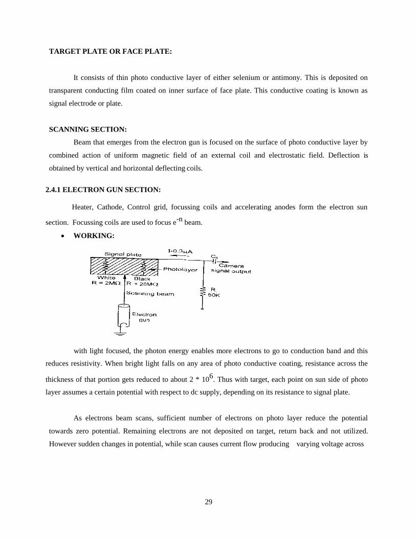
2.4.2 LIGHT TRANSFER CHARACTERISTICS:
Each curve represents the characteristic curve of a particular dark current. By adjusting the target
voltage, both dark current and sensitivity are increased.
ADVANTAGES:
1. High resolution
2. Long life, small size and low cost.
3. Gamma Cancellation circuit is not necessary.
DISADVANTAGES:
1. High dark current.
2. Poor sensitivity
3. Image lag is more.
2.5 PLUMBICON
Many of the drawbacks of videocon tube are removed in plumbicon tube. It has very fast response
and produces high quality pictures even at low light. It has small size and light weight.

31
• CONSTRUCTION:
Construction is similar to vidicon except target plate and output signal.
The target plate acts as a PIN semi conductor diode. The inner surface of glass plate is coated
with a transparent conducting layer of Sno2.
• PRINCIPLE OF WORKING:
In plumbicon each element is considered as a capacitor in series with a reverse biased light
dependent diode.
The conductive coating of Sno2 is connected to a supply of 40V through a load resistor. The
PIN diode is reverse biased and its resistance is high. So charge on capacitor is not discharged and no
current flow. Whenever light is falling on target plate, the resistance of PIN diode decrease due to photo
excitation of semi conductor junction. The current and output voltage taken across RL is directly
proportional to incident light intensity on target plate.
• LIGHT TRANSFER CHARACTERISTICS:
Output current Vs target illumination is shown. Here slope of response curve is higher
than videocon tube. Spectral response is very close to that of human eye.

32
• ADVANTAGES:
1. Reduced lag. 2. Higher sensitivity. 3. Medium size and compact.
• DISADVANTAGES
1. High Cost 2. Spectral response in poor for red colour.
S.N
o
PARAMETERS VIDEOCON PLUMBICON SATICON NEWVICON CHALNICON
1. Photo electric Photo Photo conductive Photo Photo Photo conductive conversion conductive Tin oxide SnO2
+ conductive conductive Tin oxide +
2. Material used in Antimony or lead mono oxide Selenium + Tin oxide + Cdse +
Target plate selenium + Arsenic + 2nse+znTe + cdsep3+As2s3
compound Pure PbO2 Tellurium CdTe+Sb2S3(ant
imoni tri sulphate)
3.
Sensitivity
Good
Better
Good
Very high
Good
4.
Dark Current
High
Low
Low
High
Low
5.
Speed
Severe lag
Reduced Lag
High Lag
High lag
High Lag
6.
Resolution at 400
55 %
40-50%
High
High
High line (5MHz)
7. Spectral Response Good Poor in Red Good Good Very Good
_ _
8. Gamma 0.4 to 0.9 0.9 to 1 0.9 to 1
Setting the Simple
9. Operation Simple Simple Simple target voltage is tedious.
10.
Cost
Cheaper
Costlier
Low cost
Medium
Medium
11 Size Small compact Medium Medium Medium Medium
COMPARSION OF VARIOUS CAMERA TUBES

33
2.6 CCD IMAGE SENSOR
These sensors are operating on the principal of charge coupled devices. Here a large number of CCD
array are formed together to construct the image plate.
P-type substrate, a thin layer of silicon dioxide is formed. Then by masking and etching process,
an array of metal electrodes are formed. Large number of smalls MOS capacitors are formed on the
surface of the substrate. By the application of small positive potential at the gate, every third electron is
connected to common conductor.
The spot under each metal electrode serve as a light sensitive element. These electrons are
collected in the potential well and represent the optical image. The charge stored in one element is
transfered to next element by applying more positive voltage to the next gate.
The charge movement takes place. Like this the charge is moved to the end. It is collected to form the
signal current. The one dimensional array as explained about is used to represent one scanning line.
These lines are independently addressed and output is read out using the address register and drive
phases.
ADVANTAGE
1. Good image quality.
2. Not troubled by noise.
3. No need of electron gun and beam.
LIMITATIONS
1. Requires external processing unit.
2. Relatively high power consumption.
3. Expensive.

34
APPLICATION
1. Barcode scanners.
2. Cam coders.
3. Fax machine.
2.7 VIDEO PROCESSING OF CAMERA PICKUP SIGNAL
The optical image is focused by the lens on the glass face of target plate.
The lens regulates the light, by the iris build into the lens housing. The output of video signal is
taken across the load resistor.
• IMPORTANT WORKS:
• Amplify the weak, low voltage signal from the load resistance RL.
• Addition of blanking pulses.
• Addition of sync pulse.
The signal current or voltage across the load resistance RL. So a pre-amplifier is used at the first
stage. The output terminal of camera tube to avoid external interferences.
In second stage we are using signal processor to add a blanking Rise during the horizontal and
vertical retrace intervals.
Sync adder circuit is used to add the synchronizing pulses. The output waveform has a voltage of
about IV p-p across 75 ohms as shown.
That is located at some distance from the Camera.

35
2.8 PRINCIPLE OF WORKING & BLOCK DIAGRAM OF COLOUR TV CAMERA
A colour camera tube is used to split the optical image into primary colours. A special type of
mirror called dichroic mirror is used.
That is red dichroic mirror reflect red colour and allow other colours to pass through it. The scene is
focused by the zoom lens package on the dichroic mirrosetup. Then they are passed through the colour
filters. These filters can provide precise primary colour images. Each camera tube develops video signal
voltage, proportional to the colour intensity received by it.
A video pre amplifier amplifies VR, VB VG signals. In the output stage a resistance network is
used to generate the luminance (y) signal and colour signal.
The resistance values are so related, such that Y= 0.3R + 0.59G + 0.11B. If only red colour
light is focused, then we have only red camera output VR.
Then, y =30/(30+70) * VR = .3 VR.
2.9 PICTURE TUBES
• SPECIFICATIONS:
The size of picture tube in general denotes the diagonal length. The size of the picture tube
ranges from about 1” (2.5 cm) to 30” (76 cm) or more.
Most of the commonly used tubes in B/W TV and colour TV are 51 cm and 36 cm screen size.

36
Eg:
Tube 500 AmP4 has a diagonal length of 500 mm (20”). The last alphabet ‘P’ specifies the screen
phosphor.
2.9.1 MONOCHROME PICTURE TUBE SPECIFICATION:
The commonly used picture tubes manufacture in India and marketed by Bharat Electronics
Ltd., are 310 C1p4, 470C1p4 and 610C1p4, 590 Cp4. Picture tube employs electrostatic focusing and
electromagnetic deflection.
• CONSTRUCTION AND WORKING PRINCIPLE OF MONOCHROME PICTURE
TUBES
The picture tube is used to convert the video signal into optical signals.
• CONSTRUCTION:
Mainparts :
• Electron gun
• Focusing anode
• Deflection Coils
• Final anode.
• Phosphor screen
• External conductive Coating.

37
• ELECTRON GUN
The electron gun unit consists of Cathode, control grid and accelerating anode.
It is indirectly heated by a filament Thoriatedm Tungsten or borium and strontium
oxides are having low work function and so release a sufficient number electrons of when heated.
The control grid is used to control the flow of electrons from the cathode. It is also in
the form of cylinder, end for flow of electrons.
Screen grid is maintained at 400V and focusing grid is maintained at 600V. Through this
base pin only the hated voltage for different grids are supplied.
• FOCUSSING ANODE
Electro static method is used to focus the electrons beam. The positive potential at the
accelerating anode is extended. This is considered as first lens action. Screen grid and focus grid forms
the second lens system. The focus anode is larger in diameter and also its potential is higher than the
first anode.
The voltages given to the grid are so selected that the second convergence point is on
the screen picture tube.
• DEFLECTION COILS
Electromagnetic system is used to deflect electrons beam in horizontal and vertical direction. The
picture tube produces horizontal deflection and another pair of coil placed left and right produces vertical
deflection.
The two pair of coils are collectively called as deflection yoke. In deflection yoke, centering
magnet and pin cushion magnet are also provided for centering electrons beam. At the movement of
electrons beam at corners.
• FINAL ANODE.
To provide sufficient velocity and energy for electrons beam a final anode is included in the tube.
This aquadong coating is provided with a high voltage of 10KV or more. The secondary electrons
emitted from the screen are attracted by these coating.

38
• PHOSPHOR AQUADAG SCREEN
Phosphor chemicals are light metals such as zinc and cadmium in the form of sulphate,
sulphide and phosphate compounds. The atoms while hitting the coating, hitting spot fluorescence emit
light.
• EXTERNAL CONDUCTIVE COATING.
Aquadag is also coated on the outer surface of the glass bell. A spring clip used to
connect this coating with the chassis ground. A.C. ripples in high voltage and provide a perfect higher
voltage.
• WORKING PRINCIPLE:
An a.c. supply of 6.3 V is given to the heater filament. This filament heats cathode and cathode
emits electrons. The number of electrons in the beam is controlled. The accelerating anode increase the
velocity of moving electrons A point and strike the phosphor coating on the screen. The aquadog coating
inside the tube is given a high voltage in order of to 15 kv. Because of the deflection coil current the
beam is deflected both in horizontal and vertical direction. The useful video signal is given to the
cathode or control grid. It’s called contrast control and brightness control Due to persistence of vision of
eye, the viewer accumulates all picture elements as a whole picture.
2.9.2 PHOSPHOR SCREEN:
The phosphor chemicals are light metal such as zinc and cadmium in the form of sulphate. The
kinetic energy of the moving electrons in the beam are transformed to the atoms in the phosphor coating.
External conductive coating is also outer the surface of the glass bell. Decay time of phosphors used in
picture tubes is approximately 5 ms in monochrome picture tube.
2.10 SCREEN BURN:
It is a defect in picture tube due to electrons. But the EHT voltage is present for long time.
Because of absence of deflection field there electrons continues to strike. This defect can be overcome.

39
2.11 ALUMINIZED SCREEN:
A very thin coating of aluminium is provided on the back surface of the screen phosphor on all
modern picture tubes. The aluminium coating is connected to high voltage anode coating. Aluminium
coating reflects light from the screen.
2.12 TYPES OF COLOUR PICTURE TUBES:
The screen of colour picture tube is coated with three different colour phosphor. However the
three colour phosphor are separated from each other physically.
Three types of picture tubes are
1. Delta – gun picture tube.
2. Precision – In – Line or Gun – In – Line picture tube.
3. Trinitron picture tube.
• CONSTRUCTION AND WORKING PRINCIPLE OF DELTA GUN PICTURE TUBES
DELTA GUN
Radio Corporation of America developed this tube. Arranges in delta shape.
MAIN SECTION
Electron gun consists of three electron guns spaced equally at 120 Screen and shadow mark
section.
40
• WORKING PRINCIPLE
The video signals corresponding to each primary colour are given to the three electrons
gun. The axis of even electrons beam are adjusted by the purity magnet.And during this time other
triode are by the mask.
The overall colour depends upon the phosphor which are being energised and the intensity
of each beam.Red and green beams are ‘ON’, screen become yellow.
• DRAWBACKS OF DELTA GUN TUBE:
Convergence is difficult.
Focus cannot be sharp over the entire screen, electron transparency of the mask.
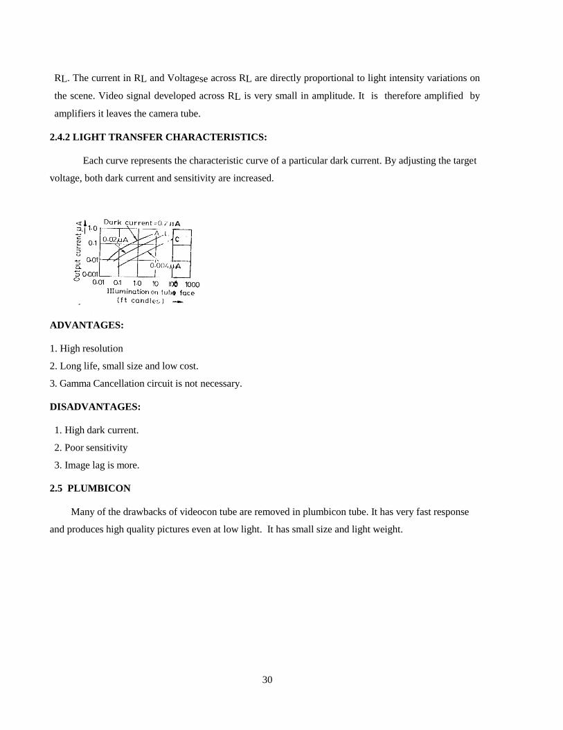
2.13 TRINITRON COLOUR PICTURE TUBE:
This type of tube was developed by Sony corporation of Japan. These tubes are having a
single gun with three in-line cathodes.
• ELECTRON GUN SECTION:
Here their is only one electrons gun, but with three cathode for each primary colour, screen and
mask construction.The outer plates are supplied with above 450V less than the final anode voltage.
Four convergence plates are used. Since green beam is in centre, it passes through the
centre plate. But red and blue beams pass between other plates. Since centre plate are connected
internally to final anode, zero potential is found between these plates. So green beam is not affected by
convergence voltage.

41
Due to voltage difference, an electronic force is developed and converging action taken
place. So convergence is done for red and blue beams.
• ADVANTAGES:
1. Construction is simple.
2. Brightness is more.
2.14 AUTOMATIC DEGAUSSING:
Degaussing means demagnetizing. It is the process of removal of magnetic flux from
magnetized parts in TV. Steel Chasis and internal frames that hold mask are subject to induced
magnetization, whenever picture tube is switched off.
These induced magnetic fields can affect the electron beam path and produce errors in colour
purity. To prevent such effect picture tubes are magnetically shielded. For this a thin silicon steel is
housed around belt of tube. Mask structure and shield material have non zero retentivity and so they get
weakly magnetized by magnetic field of earth.
Automatic degaussing circuit is shown. When the receiver is switched ‘ON’, a strong main
current passes through the degaussing coil. After a few seconds this current is dropped to very low
level.

42
REVIEW QUESTIONS
PART-A
1. What is camera tube?
2. What is picture tube?
3. Mention the characteristics of camera tube.
4. Define spectral response of a camera tube.
5. Define sensitivity.
6. Define dark current.
7. Define lag characteristics.
8. Define resolving power.
9. Mention the types of camera tubes.
10. Mention the specification of picture tube.
11. What type of focusing and deflection is used in monochrome picture tube.
12. Mention the types of color picture tube.
13. Define degaussing
PART-B
1.What is screen burn?
2.Explain aluminized screen.
3.Explain automatic Degaussing
PART-C
1. With neat block diagram explain the working and construction of Videocon camera tube.
2. With neat block diagram explain the working and construction of plumbicon camera tube.
3. Compare various camera tube
4. With neat block diagram explain the working and construction of CCD image sensor.
5. Explain with neat diagram the video processing of camera pickup signal.
6. With neat block diagram explain the working of colour TV camera.
7. With neat block diagram explain the working of monochrome picture tube.
8. With neat block diagram explain the working of delta gun picture tube.
9. With neat block diagram explain the working of Trinitron picture tube.

43
UNIT - III
TELEVISION TRANSMITTER
3.1 TWO TYPES OF MODULATION
1. HIGH LEVEL MODULATION:
In this, both the audio and video signals are amplified to the required level before modulation.
2. LOW LEVEL MODULATION:
In this, the signal is modulated before amplification.
• ADVANTAGES OF LLM (Low Level Modulation)
1. Simplicity of design.
2. Ease of operation.
3. Good linearity.
4. Superior performance.
3.2 Comparison between high level modulation and low level modulation
S.No High level modulation Low lelvel modulation
1 Both audio and video signals are amplified
to required level before modulation
Both audio and video signals are amplified to
required level after modulation
2 Transmitter power high Transmitter power is low
3 Difficult to design and operation Simple is design and operation
• Principles
A television transmitter both audio and video signals using a channel bandwidth of 7 MHz. The two
outputs, one from picture signal transmitter and the other from sound signal transmitter are combined in
suitable network and then fed to a common antenna network for transmission.

44
3.3 BLOCK DIAGRAM OF LOW LEVEL IF MODULATED TV TRABSMITTER
In this video modulation is done at IF frequency of 38.9 MHZ and sound modulation is done at IF
frequency of 33.4 MHZ. Both video and sound IF UP converted after modulation. A VSB filter is also
included at lower IF power level. After up conversion they are given to lines, amplifier for power
amplification and then it is connected to the diplexer unit.

45
3.4 VISUAL EXCITER:
Visual exciter deals with circuits related to video signals. It consists of video processing unit, video
modulator, VSB filter, Delay equalizer, Frequency up converter, Linear and power amplifier.
VIDEO PROCESSING UNIT:
In video processing unit, the Camera output signal having IVP-P amplitude is converted into standard form
by eliminating hum and noise. Also after proper amplification sync pulses and blanking pulses are added to the
Camera signal to get CVS.
VIDEO MODULATOR:
A bridge diode modulator or a diode balanced modulator is used for LLM.
In diode bridge modulator, the diodes are switched ON and OFF by the carrier voltage (Ec cos wct)

46
convert by the positive and negative half cycles. During the positive half cycle of carrier signal, RL is short circuited.
So output across RL is zero. During negative half cycle, RL is series with RS. So output is proportional to the
potential divider ratio formed by RS and RL.
Instantaneous amplitude of output voltage is,
RL
eo = ------------------- (Eo +EmSinwmt) Cos wct
RS+RL
= Ao (1+ m Sinwmt) Cos wct
From the above equation, the video signal is amplitude modulated by the carrier signal.
VSB FILTER:
It consists of four sections of LPF networks. This is used to attenuate the frequencies beyond 1.5 MHZ.
DELAY EQUALIZER:
This is used to avoid the phase distortions.
FREQENCY UP CONVERTER:
The VSB filter output and crystal oscillator output are heterodyned in the frequency UP converter stage. The
BPF is used at the output of UP converter stage.
LINEAR AND POWER AMPLIFIER:
Using the linear and power amplifier, the video signal is amplified to the required level before fed into the
diplexer.
3.5 AURAL EXCITER:
Aural exciter is used to process the audio signal. This section consists of, Audio processing unit, Audio
modulator, Audio UP converter, Linear and power amplifier.
Block diagram of aural exciter is show

47
Block Diagram of Aural Exciter
AUDIO PROCESSING UNIT:
In this section, pre emphasis circuit and amplifier are used to improve the signal to noise ratio and amplify
the audio signal to the required level.
AUDIO MODULATOR:
Audio modulator has two inputs, one is from the video processing unit and the other is from crystal
oscillator. These two frequencies are given to Varactor diode in parallel with LC tank circuit. The output is sound IF
of 33.4 MHZ.
If there is any change in sound IF, the phase detector produces an error voltage. This voltage is given to the
varactor diode to correct sound IF. Here the audio signal is frequency modulated.

48
AUDIO UP CONVERTER:
The output of audio modulator and crystal oscillator are heterodyned to produce the required audio signal
output.
3.6 LINEAR AND POWER AMPLIFIER:
Using the linear and power amplifier the audio signal is amplified to the required level and is fed into the
diplexer unit along with the video signal.
3.7 CIN DIPLEXER (CONSTANT IMPEDANCE NOTCH)
Working Principle of CIN Diplexer
Diplexer acts as the combining network, which is used to combine the audio and video signals without
mixing i.e. it provides isolation between the two inputs.

49
It consists of,
1. Two 3db Directional Couplers (DC)
2. Two Aural Notch Cavities (ANC)
These two 3db directional couplers are joined using Co-axial transmission line and two ANC’s are
connected in parallel with co-axial line.
Dc1, and Dc2 has 4 ports. Port 1 is the input port and other 3 are output ports.Visual power is fed
into port 1 of Dc1. This signal passes through port 2 and port 4 of Dc1 with 900
phase shift. Port 3
connected with dummy load to avoid leakages.
These two signals are passed through co-axial line to port 2 and port 4 of DC2 . These two are
added up and taken from port 2 of Dc2.
Audio power is fed into port 1 of Dc2, this signal divided equally into port 2 and port 4 of Dc2 with
900
phase shift. They are passed to ANC1 and ANC2 and reflected to come back to port 2 and 4 of Dc2.
The reflected signals are added and taken from Port 3 of Dc2. After this processing the audio and
video signal fed to common antenna without mixing.
3.8 BLOCK DIAGRAM OF COLOUR TV TRANSMITTER
The gamma corrected R.G, and B signals are given to the matrix network to form the Y, u and v signals.

50
The colour difference signals are fed to adder then fed to the modulator. Some samples of colour sub carrier
called as colour burst signal is also fed to the modulator using the adder circuit. The modulator take two
inputs one from adder and other from colour sub carrier generator. The sub carrier generator generates 4.43
MHZ of carrier signal. Then the output is fed into adder to combine Y signal and chrominance signal. Video
signal is amplified by video amplifier and it is AM modulated and power is amplified by power amplifier.
The audio signals from microphone are amplified by audio amplifier then it is FM modulated and amplified.
The FM modulated sound signal and AM modulated picture signal is fed into common antenna through the
combining network, a diplexer.
3.8.1 COLOUR COMPATIBILITY:
Colour compatibility means,
1. Colour television signal must produce a normal black and white picture on a monochrome receiver
without any modification.
2. A colour receiver must be able to produce black and white picture from a normal monochrome signal.
This is known as reverse compatibility.
3.9 PAL COLOUR CODER ( FUNCTIONAL BLOCKS AND WORKING OF EACH BLOCK,
OUTPUT WAVEFORMS OF DIFFERENT STAGES)

51
The gamma corrected R.G and B signals are given to matrix network and Y, R-y and B-y signals are formed.
Bandwidth of R-y and B-y is restricted to 1.3 MHZ using LPF.
Sync and blanking pulses are added with Y signal. A delay line is inserted in the path of Y signal, because
the colour difference signals (R-y) (B-y) take some time to process these signals. So to avoid this delay, a delay line
is used in Y signal path.
The colour difference signals from filter are fed to balanced modulator. The output of filter and subcarrier
oscillator is fed to balanced modulator, subcarrier generator is used to generate 4.43 MHz of carrier signal.
This carrier signal is directly fed to ‘U’ modulator,± but for ‘v’ moulduator ± 900
phase shifted carrier signal
is provided on alternate lines b y the use of 7.8 KHz switching circuit .
The DSBSC signal of U and V modulators are added together to yield the quadrature amplitude modulated
chrominance signal. Then it is passed through a BPF to remove harmonics of subcarrier frequency. Then this filtered
output is fed to adder to combine the Y and C signals.
The colour burst signal is also fed into the modulators along with U and V signals through adders. Before
feeding this burst signals into U and V adders these are passed though separate burst gate. Each burst gate is
controlled by delayed pulse at line frequency (fH).
These pulses are appeared during back porch period. During this interval ‘U’ modulator gets a burst with 900
phase shift, while V modulator gets burst with ± 900
phase shift on alternate lines. At the output of modulators, the two
burst signals are combined and produce the subcarrier burst at +450
on one line and -450
on the next line with
reference to ‘U’ phase.
The CCVS formed is fed into the main transmitter. The frequency modulated sound signal is also combined
to picture signal to diplexer and is fed into common antenna.
• Merits of Pal system
i) Differential phase error have been successfully eliminated
ii) Eliminate the hue errors, so manual hue control becomes unnecessary
iii) More picture details because greater number of scan lines
iv) Wider luminance signal bandwidth
v) Higher gamma ratio
vi) Easy studio mixing greater resolution

52
• Demerits of pal system
i) The use of phase alternation by line technique is more complicated and expensive, becuse it needs a delay
line in the receiver.
ii) This system present problems in magnetic recording
iii) More flicker – because lower frame rate
iv) Lower signal to noise ration
v) Loss of colour editing accuracy
vi) Variable colour saturation
REVIEW QUESTION
PART – A
1. List the types of modulation used in TV transmission.
2. What is diplex?
3. List out sections (components) in low level IF modulation.
4. List out the sections in aural exciter.
5. List out the sections in visual exciter.
6. What is the function of TV transmitter?
7. Mention the colour sub carrier frequency of PAL colour system.
PART – B
1. Compare high level and low level modulation.
2. What is high level modulation and low level modulation?
3. List out the advantages of LLM.
4. With neat diagram explain video modulator.
5. Explain colour compatibility and reverse compatibity.
6. List the merits (advantages) of PAL system.
7. List the demerits (disadvantages) of PAL system.
PART-C
1. With neat block diagram explain the working of low level IF modulated TV transmitter.

53
2. With neat block diagram explain the working of aural exciter.
3. With neat block diagram explain the working of visual exciter.
4. With neat block diagram explain the working of CIN diplexer.
5. With neat block diagram explain the working of colour TV transmitter.
6. With neat block diagram explain each functional block of PAL colour system.

54
UNIT-IV
TELEVISION RECEIVER
4.1 BLOCK DIAGRAM OF MONOCHROME TV RECEIVER

55
Picture 1F =38.9MHZ
Sound 1F=33.4MHZ
➢ Video signal and AGC section
➢ Audio signal section
➢ Synchronous separator section
➢ Oscillator section
➢ EHT section
4.2 Function of various blocks
4.2.1 Antenna section:
• To receive the TV signals, antenna is mounted at the top of a building. Converts the
received electromagnetic waves into electrical signals.
• A half wave length antenna is mostly used for UHF band channels. Normally yagi
antenna is used in TV receiver.
4.2.2 RF tuner section:
• RF amplifier, mixer and local oscillator are collectively called as RF tuner.
• The other input to the mixer is fed from a local oscillator
• Used to select the desired band and channel.
4.2.3 Video signal and AGC section:
• The video section consists of 1F amplifier video detector, video amplifier and picture tube.
• So a video amplifier is used at the output of video detector.
• So an automatic gain control (AGC) circuit is used to automatically control the gain of the
amplifiers.
4.2.4 Audio signal section:
• In this section we have audio IF amplifier, FM demodulator audio amplifier and loud
speaker.
• A loud speaker is used for the reproduction of sound.
4.2.5 Sync separator section:
• This section consists of a sync separator integrator and differentiator
• So the output of sync separator contains both the horizontal and vertical sync pulses.
• The differentiated horizontal sync pulses of line frequency are used to trigger the
horizontal oscillator.
4.2.6 Horizontal and vertical oscillator section
• Vertical section consists of vertical oscillator output amplifier and vertical deflection coil.
• Similarly the horizontal is synchronized by the trigger pulses from the differentiator.

56
EHT section (Extra High Tension section)
• In this section only the high voltage needed by final anode is developed.
• Using the damper diode section boosted B+
supply is taken out.
4.3 Need for AGC:
• The amount of signal received depends on the transmitter power.
• AGC also permits increase in gain for weak signals. It is achieved by delaying the application of
AGC.
• Flutter in the picture due to passing aero planes and other folding effects are reduced.
• Separation of sync pulses becomes easy.
• AGC bias voltage in a D.C voltage proportional to strength of input signal. This bias voltage is
received from output of video detector after rectification.
• This AGC bias voltage change the gain of IF and RF amplifiers in accordance with amplitude and
maintain the output of video signal as constant amplitude.
• By using AGC amplitude of video signal at output of video detector is constant irrespective of
variation of input signal.
4.4 Advantages of AGC:
• Intensity and contrast of the picture. Once set with manual controls remain almost constant.
• Contrast in the reproduced picture does not change much when the receiver is switched from one
channel to another.
• Amplitude and cross modulation distortion on strong signal is avoided due to reduction in gain.
• Fading and flutter decreases.
• Controls sound signal level.
• Sync pulses can be separated easily.
4.5 Video amplifier requirements and response curve requirements:
Requirements:
To produce a satisfactory image on the screen of picture tube, video amplifier must meet the
following requirements
4.5.1 Gain
Video signal at output of video detector is very low (2vp-p). To increase the required contrast
level in screen, video signal must be increased to high level of 80vp-p. For this video amplifier is
needed.

57
Mi
1
4.5.2 Bandwidth:
Frequency response of video amplifier must be 0HZ to 5MHZ. Then only picture without
distortion will be seen in screen. For this video amplifier is used.
4.5.3Frequency distortion:
The inequality gain at different frequency components of the signal is called frequency distortion.
Excessive frequency distortion cannot be tolerated because it changes picture information.
In poor high frequency response, rapid changes between black and white for small adjacent picture
elements in horizontal line cannot be reproduced. This result in loss of horizontal details. Low frequency
range is required for sharpness of picture. To avoid frequency distortion video amplifier is needed.
4.5.4 Phase distortion:
In video amplifiers, phase shift implies time shift , which in turn means position shift in the reproduced
picture image. So to avoid phase distortion the video amplifier should not change the phase of the
frequency component. So to avoid phase distortion video amplifier is needed.
4.5.5 Amplitude distortion (non linear distortion):
When different amplitude components get different amplifications. Then amplitude distortion
occurs. To avoid this, video amplifier is needed.
4.5.6.Frequency response curve:
F FH
• From the response curve, we find that the gain of amplifiers is reduced very much for
low frequency and high frequency.
• So HF and LF compensations are necessary for a video amplifier circuit.
Gain in DB Low
frequency frequency
High frequency
0.707

58
4.7 HF AND LF COMPENSATION TECHNIQUES:
4.7.1 High frequency compensation: (HF compensation)
• Shunt peaking.
• Series peaking.
• Combination peaking.
4.7.1.1 Shunt peaking
• Here the peaking coil L0 is connected in shunt to the video amplifier.
• C1 is stray capacitance. This reduces gain at high frequency,.
• So peaking coil will resonate with C1 and increases the gain at high frequency.
Shunt peaking

59
Shunt peaking:
VIN
0 F
The response curve of C and LO in peaking
VO
0 F
VS
Without shunt peaking With shunt peaking
0 Effects of LR F
4.7.2 Series peaking
• The peaking coil L0 is connected in series with the signal path. C is divided in to Cin and Cout.
• The reduced shunt capacitance across RL. A damping resistor Rd in shunt with its peak coil is
used to prevent any oscillation in the coil.

60
Video amplifier with series peaking
VIN
0 Effects of LR F
VS
With series peaking
0 Effects of LR F
61
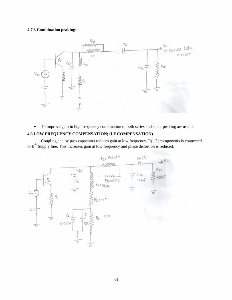
4.7.3 Combination peaking:
• To improve gain in high frequency combination of both series and shunt peaking are used.e
4.8 LOW FREQUENCY COMPENSATION; (LF COMPENSATION)
Coupling and by pass capacitors reduces gain at low frequency. Rf, Cf components is connected
to B+
Supply line. This increases gain at low frequency and phase distortion is reduced.

62
4.9 PAL COLOUR RECEIVER:
The colour TV receiver is similar to the monochrome system expect that here we have a colour
demodulator section.

63
4.9.1 The sections of the PAL colour receiver are
1. Colour chroma section
2. Colour band pass amplifier
3. Burst gate
4. Colour killer circuit
5. Colour subcarrier oscillator
6. PAL delay line and discrimination
7. Matrix network
Signal from antenna is selected by the tuner and converted to video and sound IF. It is amplified
by the IF amplifier and detected by video amplifier. Inter carrier sound IF is sent to sound IF section and
audio signal is produced. Video is amplified and sent to CRT and vertical & horizontal sync pulses are
separated and transmitted to respective sections.
4.9.2 Monochrome and tuner section:
• The RF tuner is used to select the RF signal for different channel from the antenna.
• The sync pulses for horizontal and vertical oscillator are separated by the sync separator and its
associated circuit.
4.9.3 Chrome band pass amplifier:
• This section consists of a chroma filter and two stage chroma amplifiers.
• In this section we have a color control. This control adjusts the gain of the band pass amplifier.
4.9.4 Colour burst gate:
• Separates colour burst signal and gives it to phase discriminator.
4.9.5 Colour killer:
• Zero and the output of 7.8 KHZ tuned amplifier also falls to zero.
• The colour killer turns off the chroma amplifier stage.
4.9.6 PAL Delay line stage:
• The purpose of this section is to delay the signal by about 64 micro seconds.
• The normal (U-V) and delayed (U+V) signals are simultaneously available.
Separation of U and V signals:
At the adder circuit
(U-V)+ (U+V) =2U
(U+V)+ (U-V) =2U
At the subractor circuit
(U-V)- (U+V) = -2V
(U+V)- (U-V) =2V

64
RL
C1 V0
Q1
2µf R1
50
For adder and subractor 64 microns seconds delay signal needed. To provide this PAL delay line is
needed.
4.9.7 Colour subcarrier oscillator:
• Keeping colour bunt as reference produce carrier signal of 4.43 MHZ.
4.9.8 Matrix network:
To generate (R-Y) (B-Y) and (G-Y) colour signals from U, V&Y signals matrix network is needed.
4.10 Need for synchronization pulse separator:
• The horizontal and vertical sync pulses exist in the top 25 percent of the composite video signal.
• At the output of video detector we have composite signals that contain video information and
sync information for triggering of oscillator only sync pulses are needed.
• The sync separator separates both the horizontal and vertical sync pulses from the composite
video signal.
• By using differentiator circuits, horizontal sync pulses (15625 HZ) are separated and by using
integrator, vertical sync pulses (50HZ) are separated. They are used for triggering corresponding
oscillators.
4.11 Basic principle of synchronization pulse separator:
vcc
Video
Input

65
Saturation
IC COLLECTOR CURRENT PULSES
Dynamic
Characteristics
t
Reverse bias forward bias
Horz sync pules
Slicing level
Effective bias line
• The basic principle of merely biasing the devices used in sync separator the composite video
signal makes current flow in the device.
• In self biasing the DC bias voltage is produced by the input AC signal itself.
• The transistor is operating the class ‘C’ mode. Input stage provides necessary DC bias voltage.
• R&C is used to provide the self bias between base and emitter of the transistor.
• Emitter circuits conduct heavily and changes the capacitor ‘C’. This negative voltages then
reverse bias the emitter bias base junction.
• The peaks of consecutive input video signal discharge through RC .discharge only 10% between
the peak input signals.
• So the output of transistor we have only the separated sync pulses. These are shown clearly.
4.12 Condition must be satisfied
• β of the transistor should be large.
• Output leakage current must be small.
• The time constant RC must be long.
• A low power transistor can be used, since the transistor is off for most of the period.

66
4.13 Block diagram of sync separator:
To cathode to
Picture tube
50HZ
To
Vertical deflection
coils in the yoke
DC voltage control
The video signal from the video amplifier is fed to the sync separator circuit.
• At the output of sync separator we have a train of horizontal and vertical sync pulses.
• After the proper amplification they are fed to vertical deflection coil.
• Similarly the horizontal deflection oscillator is triggered by the differentiator output.
• To maintain the horizontal frequency at constant value an automatic frequency circuit is used in
horizontal deflection section.
VERTICAL
DEFLECTION
OSCILLATION
AND WAVE
SHAPER
LPF
INTEGRATOR
VERTICAL
DEFLECTION
AMPLIFIER VIDEO
AMPLIFIER
NOISE
CANCELLING
CIRCUIT
SYNC
SEPERATOR
LINE
DRIVER
AND
OUTPUT
STAGE
LINE
DEFLECTION
OSCILLATOR
AND WAVE
SHAPER
HPF
OSCILLATOR LINE AFC
NETWORK

67
4.14 Separator (Vertical and Horizontal Sync)
4.14.1 Vertical sync separator: (INTEGRATOR CIRCUIT) LPF
• The resistor R, capacitor C forms a low pass filter which act as an integrator circuit.
• The time constant RC is chosen to be much larger than the width of separated vertical pulses.
• Usually about 10 times the serrated pulse width is sufficient when the horizontal sync pulses and
equalizing pulses are applied to integrator.
Integrator circuit:
• The C charges and discharges quickly and the duration of ON period of these pulses are very less
compared to time constant RC.
• The capacitor is charged for a period of 27.3 micro seconds and discharge for a period of only 4.7
micro seconds. This process is repeated.
• So, once a again capacitor is charged for 27.3 micro seconds and discharges for only 4.7 micro
seconds this process is repeated.
• Due to this the voltage across the capacitor is gradually increased with small spikes super
imposed on it.
• If vertical sync pulses has passed then the integration capacitor discharge almost to zero.
• In general a time constant of 50µs to 60µs is set for the integrator circuit.
4.15 Horizontal Synchronous Separator: Differentiator (HPF)
• When the leading edge of incoming pulse train is applied to RC, the output waveS follows almost
the shape of input leading edge.
• When the flat top rectangular wave is reached, no further charging with time constant.

68
• Since the time constant is very short compared to input pulse, discharge completes before trailing
edge of input pulse occurs.
• When trailing edge input pulse occurs it produces another pulse of opposite polarity to that of first
pulse.
• Since horizontal frequency is very high this will be affected by noise so horizontal AFC is
provided.
4.16 Automatic frequency control: (AFC)
Noise pulses which arrive during intervals between sync pulses tend to trigger the drive oscillators
prior to their proper time. Picture rolls vertically upwards or downwards in vertical oscillator is so triggered
and a series of lines will be jumped up in horizontal oscillator causing tearing of picture. This system is
automatically controlled by using AFC circuits. AFC means Automatic Frequency Control. To maintain
synchronization AFC is needed.
4.17 Need for AFC:
AFC means automatic frequency control. Horizontal and vertical sync pulses are separated using
HPF and LPF.Vertical sync pulse frequency is 50HZ. So it is not affected by noise pulses. But horizontal sync
pulses frequency is 15625 HZ. So it is affected by noise pulses. This causes out of synchronization. So to maintain
constant frequency AFC is needed.

69
4.18 Block diagram of horizontal AFC:
It consist of
1. Sync discriminator.
2. Horizontal oscillator.
3. Horizontal output amplifier.
The horizontal synchronization voltage and fraction of horizontal output voltages are given
to sync discriminators terminals. It detects difference frequency and develops dc output voltage proportional to
difference voltage. This DC voltage is fed to large time constant filter and output of which is used to control the
oscillator frequency. The capacitor in the LPF terminates the effect of noise pulses.
4.19 Hunting in AFC:
The low power frequency followed by differentiator controls the performance of AFC. If time constant is
too large control is sluggish. If time constant is low oscillator is hunt while returning to the correct frequency.
Excessive hunting in AFC circuit appears as “WEAVING” or “GEAR-TOOTH” effect on picture. Hunting in
AFC is shown.

70
15626 HZ
Time 15623 HZ
Error Voltage without Anti
15624 HZ
hunt
Because of hunting effect horizontal frequency deviates from correct values. To prevent this
hunting double section filter is used.
4.20 ANTI-HUNT network:
R1C1 time constant of 5ms is large enough to filter noise, horizontal sync and fly back pulses effects. Second
section R2C2 in series is known as “ANTI HUNT” network.
In anti hunt network R2 act as a damping resistance across C1 making output voltage more resistive and
less capacitive. Because of addition of anti hunt network the time delay in charge of control voltage is reduced.
HO
RIZ
ON
TA
L O
SC
ILL
AT
OR
FR
EQ
UE
NC
Y

71
1
15626 HZ
Oscillator frequency hunting
5623 HZ
15624HZ
REVIEW QUESTION
PART-A
1. List out the sections (components) of monochrome TV receiver.
2. List out the values of picture IF and sound IF in TV transmission.
3. What is AGC?
4. List out the sections of PAL color receiver.
5. What is sync separator?
6. What is the function of colour killer section?
7. What is AFC?
HO
RIZ
ON
TAL
OSC
ILLA
TOR
FR
EQU
ENC
Y
Erro
r vo
ltag
e

72
8. Why AFC is used in horizontal section?
9. What is an antenna?
10. Mention the types of FM sound detectors?
PART-B
1. Explain the need of AGC.
2. List the advantages (merits) of AGC.
3. Mention the video amplifier requirements.
4. Explain the need for sync pulse separator.
5. With neat diagram explain integrator (vertical) or (LPF) working in details.
6. With neat diagram explain differentiator (or) HPF working in details.
7. Explain the need for AGC.
8. What is hunting in AFC?
9. What is anti hunt network?
10. What is the compensation technique employed to extend the bandwidth of an amplifier?
PART-C
1. With neat block diagram explain the working of monochrome TV receiver.
2. With necessary diagram explain the HF and LF compensation technique.
3. With neat block diagram explain the working of PAL color receiver.
4. With neat block diagram explain the working of basic principle of sync pulse separator.
5. With neat block diagram explain the working of sync separator.
6. With neat block diagram explain the working of hunting in AFC.
7. Explain the anti hunt network in detail.
8. Explain the requirement of video amplifier in detail.

73
UNIT V
ADVANCED TELEVISION SYSTEM
5.1 Block diagram of digital colour TV receiver:
• Digital television means the digital processing of TV signal both at the transmitter and at
the receiver.
• The luminance and chrominance signal process are in digital form.
• The central control unit is a microcomputer based device used to control and coordinate
all circuit in this receiver.
• The main block used in digital receivers are,
1) Video codec
2) Video processor
3) Deflection processing unit
4) Audio codec
5) Audio processor
6) Central control unit

74
5.1.1 Video codec:
The signal from the IF stage is converted to analog CVS by the high speed flash A/D converter
into 8 bit digital signal and given to video processor.
5.1.2 Video processor:
The output of video codec is separated into two channels – luminance and chrominance.
Brightness and contrast of luminance signal are adjusted in accordance with user’s settings. Chrominance
signal is encoded to relative weightage of red, green and blue.
These signals are then given to video codec. The D/A converter in video codec convert it to
analog form. By the delay line technique and demodulation R,G,B signals are obtained amplified and
applied to corresponding guns.
5.1.3 Deflection processing unit:
This unit senses the standard TV signals and synchronizes the vertical and horizontal sweep
generators and amplified and given to corresponding deflection yokes.
5.1.4 Audio codec:
This samples the input signal to produce 1 bit data stream and convert this into 16 bit resolution
stream. This is given as input to audio processor.
5.1.5 Audio processor:
The input signal is split into two channels. Then the stereo balance, tone, loudness, and other
necessary function are controlled.
5.1.6 Central control unit (CCU):
It is a microcomputer based device used to control and coordinate all circuits in the receiver. It is
supported by an EEPROM, a timer, a control bus and circuits to decode user commands.
5.1.7 Merits of digital receiver:
• Resolution is high
• No interference of electrical appliances
• Synchronization is better.
• Picture in picture is possible.
• Improved reception in for fringe areas.

75
5.2 Remote control circuit:
• To operate the various receiver controls from a distance by the viewer, he is provided by
the remote control circuits.
• The main function done by it are changing the channels, varying the sound level, turning
ON and OFF the TV set , contrast level.
• Two signaling methods used for remote control.
1) By ultrasonic waves
2) By infrared wave using LED’S.
• We have 11 buttons for channels selection, one for VCR connection. Power ON / OFF
button, volume control, color control are provided.
• The remote transmitter is somewhat directional since we are using the infrared waves.
• We can operate within 7 meters and at a radians of 30º from the receiver point, labeled for
remote operation.
5.3 Remote control IR transmitters:
• To achieve all the necessary basic function 24 different commands are needed. So 24
different pulse patterns are generated. The modulator IC (encoder) performs the main
function.

76
• The waves are modulated through a 480 KHZ carrier by one of the 24 pulse pattern.
• If any one of the key is pressed, it produces a distinctive pulse train which modulates the
crystal controlled 480KHZ carrier.
• After proper amplification, it is fed to LED driver (Q1).The output of the Q1 drives the
infrared LED D1 and D2 then the IR signal is transmitted.
• Then the function indicates LED D3 comes to ON state.
• If the LED is not glow on depression of a button then it indicates that the battery is to be
replaced.
5.4 Remote control IR receiver:
• A simplified circuit diagram used for the synthesis of remote control receiver.
• The remote infrared sensor D1 is used to pick up the pulse modulated infrared
signals send by the IR transmitter.

77
• The A.C signal picked up by D1 is fed to the FET Q1 for some amplification.
• The output of Q1 is given to emitter follower Q2 through remote processor and
given to pulse shaper. Here signal is amplified and then demodulated.
• Demodulated distinct pulses belong to distinctive function.
• This is given to microcontroller.
• This microcontroller on receiving different pulses produces different output
necessary to perform the ordered function.
For example:
• The power ON/OFF button is pressed it is demodulated by the receiver then the
micro computer output at the receiver is a positive voltage.
• Positive voltage through a 33k resistor turns ‘ON’ the transistor Q3and operates
the opto coupler and lamp is now glowing.
• The resistance of LDR decreases. Due to the resistance 220 V A.C applied to the
gate of the transmitter, theTRIAC comes to ON state, so the TV receiver is
switched ON.
• To turn the receiver OFF the ON button of the transmitter is pressed once again.
• The positive voltage to the base of Q3 is removed the TRIAC is deactivated and
so the lamp goes OFF in the opto coupler unit.
• So the AC supply to the receiver is cutoff. The above sequence is repeated for
successive depression of the ON/OFF button.
Similarly several different circuits are employed at the output of microcontroller to achieve
different functions like volume control, color control and contrast control etc.
5.5 CCTV (closed circuit television system):
If a single camera output is given to TV receiver through cable or the output of many cameras is
connected to a TV monitor,then the system is called CCTV system.
Two types of switching network are made possible between the camera and TV monitor.This
makes us to select the camera / monitor. Both CCTV systems is shown,

78
In diagram (a) a single camera(C) is connected to many monitors (M) through switching network
(SN).in this we can see a single program in monitors at many places.
In diagram (b) many cameras(C) are connected to single monitor (M) through switching network.
In this at single place, we can see many programs happening at different places.
5.5.1 Application of CCTV:
1. Education – lecture classes and demonstration experiments.
2. Business - used to keep on eye over customer and sales personal
3. Home – seeing the caller before opening the door.
4. Industries – for remote inspection of objects in place where human resources cannot be used.
5. Aerospace & oceanography: To see the inaccessible objects or places.
6. Medicine: To visualize the surgery.
5.6 Scrambler-Necessity-Basic Principles
This channel provided by the cable TV owners to its customers is of two types.
They are
1. Basic services
2. Premium services
Several basic channels and local TV programmes offered by cable companies for a minimum
charge level is called basic services.
For new movies, sports etc., separate channels are provided with additional charges called as
premium services.
Cable TV connections provided for viewing premium services with additional chargesis called as
Conditional Access System (CAS).
In TVs provided with CAS connection only premium service programmes to be received.
For TVs provided with basic services connections premium services channel follow certain
methods different from basic services. This is called scrambling. Equipments used for scrambling is
called as scrambler.
5.7 Types of scrambling:
1) TRAP:
Here the signal is blocked by inserting and interfering carrier in the pay channel and notching it
out.

79
2) Sync suppression scrambler:
Here the sync details from RF signal is removed and transmitted. So in basic services channels
without H and V sync pulses pictures cannot be reproduced. Without sync pulses reference for AGC is
also not provided. Without AGC bias contrast is overloaded.
So the picture continuously rolls with horizontal tearing of video signal.
3) Data encryption method:
In this method the audio and video signals are converted to digital forms. They are encoded using
digital signal processing method. This is called as data encryption.
4) Baseband scrambling:
In this method the polarity of the randomly selected H- line is inverted. Line code for that
particular H- line is transmitted with the video band.
5.8 Descrambler:
For channels that are scrambled, the signal cannot be reproduced normally. For that descrambler
are needed. Signals that are scrambled is descrambled by an equipment is called descrambler. This
process is called descrambling.
Descrambler block diagram:
• Descrambler reverses the effect of scrambling at the head end of the cable system. Simple
sync suppression scrambling and descrambling method is mostly used.
• In this sync signals from the final output is removed and this information is sent through
a pilot carrier.
• for this purpose a pilot carrier signal having a frequency lower than that of the selected
channel is used.

80
• Channel signal in the pilot signal is separated by the tuned amplifier.Pilotfilter, filters the
sync details from the pilot carrier. AM detector demodulates this. In the demodulated signal
timing information needed for synchronization is available. For proper shaping, pulse shaping is
provided. Keyed RF alternator is provided for mixing the sync signalwith channel signal.
Alternator is represented by resistor Ra.Keying by pass action is provided by diode. This is
represented by‘s’.
5.9 Telecine equipment:
In cinema cameras 24 frames per second is used. But for television 25 frames / second is used. So
the pictures taken by movie camera is used for TV broadcast means, then it should be first converted to
TV standards. The equipment used for this purpose is called telecine equipment.
510 Digital CCD telecine equipment:
Telecine equipment using CCD sensors that operate digitally is called as digital CCD telecine
equipment. Block diagram is shown below.

81
Cine film is illuminated by slit of light. This represents H- line in TV scanning. By using dichroic
prismatic splitters this light is separated to basic colors R,G and B. then it is given to separate CCD image
sensors.
To correct the RGB sensitivity from the three CCD sensors, neutral density filters are used. The
linear array in each CCD sensors contains 1024 elements. This represents H-line. By charge transfer
method, the information’s are moved in H – direction. Then H- scanning takes place. Then this is given to
A/D converter and converted to digital signal.
Then by digital processing gamma correction and black level clamp is done. Then this is given to
matrix network to produce B-Y, R-Y, and Y signals. Then it is digitized and separated to luminance and
chrominance signal and stored in memory. This will be in sequential.
In TV transmission interlaced scanning is used. So from memory lines are read and stored in field
1 and field 2. Then this is given to D/A convertor, then the RGB signals are got and coded to required
system (PAL and NTSC) and the output is got.
5.11 Introduction to high definition TV:
High definition television (HDTV) provides a resolution that is substantially higher than that of
standard definition television. In HDTV, recent digital techniques are used for processing television
signals. The aim of this HDTV are given below,
I. Improvement in both vertical and horizontal resolution of the reproduced picture by
approximately 2:1 over existing standards.
II. Much improved color reproduction.
III. Higher speed ratio at least 5:3 and
IV. Stereophonic sound
Their implementation result is a picture quality as clear as obtained from 35mm cine films and sound
as good as from digital audio discs.
HDTV may be transmitted in various formats.
i. 1080p → 1920 x 1080p : - 2.1 megapixel (MPx) per frame
ii. 1080i → 1920 x 1080i : - 2.1 megapixel (MPx) per frame
→1440 x 1080i: - 1.6 megapixel (MPx) per frame
iii. 720p → 1280 x 720p : - 0.9 megapixel (MPx) per frame
The letter ‘P’ stands for progressive scan while ‘I’ indicates interlaced. Interlaced is fine for still
and slow moving images. Progressive is fine for high speed video.
5.12 3D TV:
The two dimensional (length and breadth) pictures as we see on the television receiver screen look
flat because these lack depth. However in three dimensional (3-D) appears to have all the qualities of a
live scenes as viewed with natural vision. The 3-D picture scenes to extend beyond the screen at its back
and also in the front.

82
The block schematic of a possible 3D picture and stereo sound receiver is shown in
figure.
The RF amplifier in the tuner has a bandwidth of over 12 MHZ and enough gain to feed
sufficient amplitude of RF signal to the mixer (converter) circuits for easy separation of USB and
LSB modulation components. The two RF sideband signals are separated by BP filters for
feeding to corresponding mixer circuits. The USB IF signal is derived from the RF LSB signal by
beating with the carrier equal to (fc –IF) MHZ. from this stage onwards the two IF signals are
processed separately, as in a conventional colour TV receiver to obtain the right and left channel
RGB video signals.
The sync pulses are obtained from the composite video signal produced through video IF
subsystems. On clipping and processing, these are fed to the vertical and horizontal(line)
oscillator circuits for synchronizing, to obtain a steady raster. The right and left channel 5.5 MHZ
SIF signals are separated by trap circuits and demodulated in the usual way to feed the two stereo
sound loudspeakers.
5.13 BLUE RAY:
5.13.1 Introduction:
Blue ray (or) Blue Ray disc is a next generation digital video disc. It is optical disc storage medium. It
was introduced in 1996. It can, record, store, rewrite and play back high definition(HD) video and digital
audio as well as large amounts of data.
A single layer BD can store up to 25GB of data and a double layer can store up to 50GB of data.

83
5.13.2 Disc parameter:
The following table shows the characteristics of BD.
Parameters
Disk diameter
120 mm
Disk thickness
1.2 mm
Laser wavelength
405 nm
Numerical aperture
0.85
Minimum pit length
0.138µm
Data rate
36 Mb/sec
Number of sides
One or two
Number of data layers
One or two
Data capacity
Single layer : 25 GB
Double layer : 50 GB
5.13.3 RECORDING AND PLAY BACK PRINCIPLES:
The recording and play back principle is described in the following figure

84
• Recording:
The binary data modulator encodes the NRZI signal according to the 17PP rule. The encoded
signal is sent to a write pulse compensator. In which the signal is modulated to multi-pulse. The
modulated pulse waveform is sent to a laser driver circuit. The laser driver circuit modulates the power of
laser beam to record data on Blue – Ray disc.
• Playback:
To playback the recorded data, the reproduced signal through an equalizer is given to the Phase
Locked Loop (PLL).The output of the equalizer is also given to the analog to digital (A/D) converter. The
(A/D) converter converts the signal to digital. It is at the clock timing of PLL. Then the signal is passed
through a PRML channel to correct the initial bit error. The output is the NRZI signal. It is sent to the
subsequent digital signal processing unit.
5.14 Block diagram of DVD player:
Important sections and their working is explained below.

85
5.14.1 Optical pickup section:
Using disc motor, DVD rotates. Laser pickup assembly identities the pits and lands in the tracks
of rotating disc and gives the corresponding output voltage. DSI (data search information) navigate
according to user requirement and gives servo signals for motor rotation according to read data.
5.14.2 DVD data processor:
DVD is modulated with 8 to 16 coding. This is demodulated and compared with details in ECC
(Error Correction Code) and it is corrected if there is any error.
After that this is descrambled and verified using EDC(Error Detection Code)
While recording datas are multiplexed and stored. For demultiplexing, it is sent to stream
demultiplexer.
5.14.3 CD Data Processor:
DVD player can read CD also. In CD data is modulated by 8 to 14 methods. After demodulation
by using ECC. It is verified and the output data is sent to analog and digital output.
Stream demultiplexer:
In DVD at end of each sector EDC will be there. Using this, data is verified and sent to stream
demultiplexer. Here all data (audio, video, subtitles) are multiplexed.
Here except MPEG audio / video others are marked as private stream.
By using remote control particular data is selected by using navigation manager data is operated.
That selected data is sent to the respective decoders.
5.14.4 Decoding Section:
For each stream there will be distinctive decoders. By using decoders decoding is completed. If
digital output is needed it is directly taken as digital and if analog output is needed by using DAC, analog
output is taken.
5.14.5 Abbreviations used in block diagram:
ECC:Error Correction Code.
EDC: Error Detection Code
PCM: Pulse Code Modulation
PCI: Presenting Control Information
DSI: Data Search Information

86
5.15 Desirable features and output of DVD player:
• Since there is no physical content with the disc as it revolves the quality of pictures and sound in
DVD.
• Movies on DVD can be seen in wide screen format and we can get an experience of watching in a
cinema theatre.
Capacity:
• Single layer DVD hold over a 2 hours and dual layer hold 4 hours over.
• Still picture accompanied by hundreds of hours of audio and next.
Noise
• Most of the LD player make a whirring noise
Video
• DVD use digital video technique
Availability:
• DVD player and disc are available for purchase and rental in thousand of output in internet.
Price:
• Low cost DVD player are cheaper than the cheapest LD player. Most movies on DVD less than
on LD.
5.15 USB flash drive (PEN DRIVE)
USB flash drive is a small portable flash memory card. This can be plugged into computer USB
ports and function like a portable hard drive. This drive is otherwise called thump drive or jump drive or
pen drive or key drives. These drives were introduced by IBM in December 2000. The figure given below
show the structure of a flash drive.

87
A flash drive consists of a flash memory chip (EEPROM) protected inside a plastic
metal. The USB connector is in one side and is protected by a removable cap. Most of the flash
drives are preformatted with FAT or FAT 32 file systems. Each sector is of 512 bytes and the
first sector contains a master boot record and partition table.
Therefore flash drive can be partitioned as hard drives. Flash drives are available is various
capacities such as 1 GB, 2GB, 4GB etc.
5.15.1 Features:
I. Flash drives are resistance to scratches and other mechanical damage.
II. It is very small, so it can kept inside the user’s pocket.
III. Storage capacity is higher than a DVD.
IV. It can be used as audio player.
V. It uses less power than hard disk.
VI. The user can insert the flash drive into the computer and use it immediately.
REVIEW QUESTION
PART – A
1. What is scrambling?
2. What is descrambling?
3. What is CCTV?
4. List out some models of DVD.
5. Expand HDTV, CCTV and DVD.
6. List out the types of scrambling method.
PART-B
1. List out some applications of CCTV.
2. Explain the types of scrambling.
3. List out some features of DVD.
4. Explain CCTV in detail.
5. What is telecine equipment?
88
PART-C
1. With neat block diagram explain the working of remote control IR transmitter.
2. With neat block diagram explain the working of remote control IR receiver.
3. With neat block diagram explain the working of descrambler.
4. With neat block diagram explain the working of digital CCD telecine equipment(System).
5. With neat block diagram explain the working of 3DTV.
6. With neat block diagram explain the working of DVD.
7. With neat block diagram explain the working of blue ray disc.
8. Explain in detail the USB flash drive (pen drive).
9. With neat block diagram explain the working of digital colour TV receiver.
1.


![Sessi 07/08 Final Exam [ZCT 104] - fizik.usm.my fileSessi 07/08 Final Exam [ZCT 104] - 3 - B. It is possible for the electron beam in a television picture tube to move across the screen](https://img.pdfslide.us/doc/110x75/5cb0085b88c993ca528b8d02/sessi-0708-final-exam-zct-104-fizikusm-0708-final-exam-zct-104-3-b.jpg)